radiating cable - acma.gov.au · part part description stock ... aes gsm air gwy bts eik,norway...
TRANSCRIPT


(800) TMS-COAX • www.timesmicrowave.com168
TIMES MICROWAVE SYSTEMS
RA
DIA
TIN
G C
AB
LE
Engineered Products:T-RAD-60050 Ohm Leaky Feeder Coaxial Cable
• Provides RF coverage in buildings, mines and other enclosed areas• Offers broadband performance up to 2.5 GHz• Flexible, non-kinking design provides easier installation• Accepts standard "EZ" crimp connectors used for LMR-600 cable*
Environmental SpecificationsPerformance Property 0F oC
Operating Temperature Range -40/+185 -40/+85 Frequency (MHz) 150 450 900 1900 2400Attenuation dB/100 ft 1.34 2.22 3.35 5.30 6.40
Attenuation dB/100 m 4.39 7.28 10.98 17.38 20.99
Coupling Loss** dB 54 61 68 69 67
* Request T-RAD-600 connector data sheet and attachment instructions** Coupling loss measured at 6.5 feet (2 meters) *** Patent applied for
Mechanical SpecificationsPerformance Property Units US (metric)
Bend Radius: installation in. (mm) 1.5 (38)
Bend Radius: repeated in. (mm) 6.0 (152.4)
Weight lb/ft (kg/m) 0.09 (0.137)
Electrical SpecificationsPerformance Property Units US (metric)
Velocity of Propagation % 86Dielectric Constant NA 1.35Time Delay nS/ft (nS/m) 1.18 (3.87)Impedance ohms 50Voltage Withstand Volts DC 4000Jacket Spark Volts RMS 6000
Part Part Description StockNumber Application Jacket Color Code
AA 9096 T-RAD-600-PVC PVC Black 44030
AA-9097 T-RAD-600-FR FRPE Black 44031 Loss & Coupling vs. Frequency (typical)
(db
per
100
fee
t)
10
9
8
7
6
5
4
3
2
1
70
68
66
64
62
60
58
56
54
52
50
db
@ 6
.5'
Frequency (MHz)
Construction SpecificationsDescription Material In. (mm)
Inner Conductor Solid BCCAl 0.176 (4.47)
Dielectric Gas-Injected Foam Polyethylene0.455 (11.56)
Inner Shield Bonded Aluminum Tape 0.458 (11.63)
Jacket See table above 0.530 (13.46)
l l l l l150 450 900 1900 2400

(800) TMS-COAX • www.timesmicrowave.com 169
TIMES MICROWAVE SYSTEMS
RA
DIA
TIN
G C
AB
LE
ConnectorsInner Outer Finish*
Part Stock VSWR** Coupling Contact Contact Body Length Width WeightInterface Description Number Code Freq. (GHz) Nut Attach Attach*** /Pin in (mm) in (mm) lb (g)
7-16 DIN Male Straight Plug EZ-600-716-MH 3190-503 <1.25:1 (2.5) Hex Spring Finger Crimp S/S 2.0 (51) 1.30 (33.0) 0.254 (115.2)
N Male Straight Plug EZ-600-NMH-D 3190-1268 <1.25:1 (2.5) Hex/Knurl Spring Finger Crimp A/G 2.1 (53) 0.92 (23.4) 1.164 (74.4)
Right Angle EZ-600-NMH-RA 3190-762 <1.35:1 (6) Hex Spring Finger Crimp S/G 2.1 (53) 0.92 (23.4) 0.185 (83.9)
N Female Straight Jack EZ-600-NF 3190-955 <1.25:1 (2.5) NA Spring Finger Crimp S/G 2.3 (59) 0.87 (22.1) 0.150 (68.0)
Bulkhead Jack EZ-600-NF-BH 3190-616 <1.25:1 (2.5) NA Spring Finger Crimp S/G 2.4 (61) 0.88 (22.4) 0.195 (88.5)
TNC Male Straight Plug EZ-600-TM 3190-418 <1.25:1 (2.5) Knurl Spring Finger Crimp S/G 1.7 (43) 0.59 (15.0) 0.112 (50.8)
Reverse Polarity EZ-600-TM-RP 3190-796 <1.25:1 (2.5) Knurl Spring Finger Crimp A/G 2.2 (56) 0.87 (22.0) 0.112 (50.8)
TNC Female Reverse Polarity EZ-600-TF-RP 3190-797 <1.25:1 (2.5) NA Spring Finger Crimp A/G 2.3 (58) 0.87 (22.0) 0.100 (45.4)UHF Male Straight Plug EZ-600-UM 3190-615 <1.25:1 (2.5) Knurl Spring Finger Crimp S/G 1.7 (43) 0.88 (22.4) 0.164 (74.4)
* Finish metals: N=Nickel, S=Silver, G=Gold, SS=Stainless Steel, A=Alballoy **VSWR spec based on 3 foot cable with a connector pair*** Requires separate crimp ring; contact TMS engineering
EZ-600-716MH EZ-600-NMH-D EZ-600-NMH-RA EZ-600-NF
EZ-600-NF-BHEZ-600-TM EZ-600-TM-RP
EZ-600-TF-RP
EZ-600-UM

Commercial in Confidence
AeroMobile™Product Overview Document
Dec 2005AeroMobile Ref: Product Overview Draft C

- 2 -
Editor Issue Date Reason for changeJohn Little Draft A 20th Nov 05 BaselineJohn Little Draft B 1st Dec 05 Added more details to
Appendices,John Little Draft C 22nd Dec 05 Added Software Section, Ground
Infrastructure and Geir Lovnescomments

- 3 -
1 Introduction.................................................................................................................... - 5 -2 AeroMobile System and Avionics Overview .................................................................. - 8 -3 AeroMobile Software Overview ................................................................................... - 16 -4 AeroMobile Ground Infrastructure Overview ............................................................... - 25 -5 Certification ................................................................................................................. - 27 -6 Appendix A - BTSRFU (A6129665000-1/2 and A6129666000-1) Outline Spec........... - 34 -7 Appendix B - CRFMU (A6129664000-1 and -2) Outline Spec ..................................... - 38 -8 Appendix C - Aerial Combiner Unit (AA6129663000-1) Outline Spec......................... - 49 -9 Appendix D Server (AA6129661000-1) Outline Spec .................................................. - 54 -10 Appendix E Control Panel (A612966200-1) Outline Spec ........................................ - 57 -

- 4 -
Objective
The objective of this white paper is to give the reader a basic understand of thecomponents that make up the AeroMobile system; how the system manages the on-board BTS and CRFMU ; the operation of the RIAS and the certification aspects of thesystem.
Disclaimer
The information contained in this document is subject to change at anytime byAeroMobile
CopyrightThe information contained in this document supplied under NDA and is commerciallysensitive under no circumstances should this document be disclosed to a third partywithout written permission from AeroMobile.

- 5 -
1 IntroductionUsing a GSM mobile phone on an aircraft just as you would on the ground was oneof our key design criteria’s. The aircraft environment will be treated as a “GSMcountry” in the sky and users will simply roam into and out of this new “country” asthey would when traveling abroad.
For the good reasons outlined within the FAR 91.21 safety announcement mobilephone use will be limited to cruise altitudes only in much the same way use oflaptop computers and other electronic devices are controlled today.
The on-board service will be provided by AeroMobile, a virtual GSM telco jointlyformed by ARINC and Telenor. Accordingly AeroMobile will have roamingrelationships with other Telco’s to ensure all combinations of passenger serviceprovider can operate on-board. Telenor’s affiliation and commercial relationshipswith Telenor Mobile will be leveraged to satisfy this requirement.
Each month when the passenger receives their monthly bill any traffic resulting froma flight will be simply identified as roaming usage, similar to any other roamingtraffic.
We recognize that many airlines are, or plan, to operate a mixed fleet of aircraftinstalled with several flavors of SATCOM technology. Using AeroMobile’s patentedtechnology it is possible to scale a single product offering across a complete fleet ofaircraft irrespective of the off aircraft SATCOM technology used. The matrix shownbelow outlines the service levels and capabilities of AeroMobile when aligned withthe various SATCOM technologies:
Supported
Supported
Supported
PrePaidCards
NotSupported
NotSupported
SupportedSupported(unlimited)
Supported(5 -6 calls)
InmarsatClassic(H / H+)
SupportedSupportedSupportedSupported(unlimited)
Supported(TBD)Ku band
SupportedSupportedSupportedSupported(unlimited)
Supported(up to 32 callsper channel)
SwiftBB
802.11x(Wi-Fi enabled
phones)
GPRS(Blackberry,MMS, email
etc)
Supplementaryservices
(caller ID, call waitingetc)
ShortMessaging
Service(SMS)
Voice calls
Supported
Supported
Supported
PrePaidCards
NotSupported
NotSupported
SupportedSupported(unlimited)
Supported(5 -6 calls)
InmarsatClassic(H / H+)
SupportedSupportedSupportedSupported(unlimited)
Supported(TBD)Ku band
SupportedSupportedSupportedSupported(unlimited)
Supported(up to 32 callsper channel)
SwiftBB
802.11x(Wi-Fi enabled
phones)
GPRS(Blackberry,MMS, email
etc)
Supplementaryservices
(caller ID, call waitingetc)
ShortMessaging
Service(SMS)
Voice calls
The economics of delivering cellular services over satellite at a price point alignedto current GSM roaming rates is just one example of the economic savings
- 6 -
associated with the very small service value chain in support of AeroMobile (ARINC& Telenor).
1.1 Overall Architecture
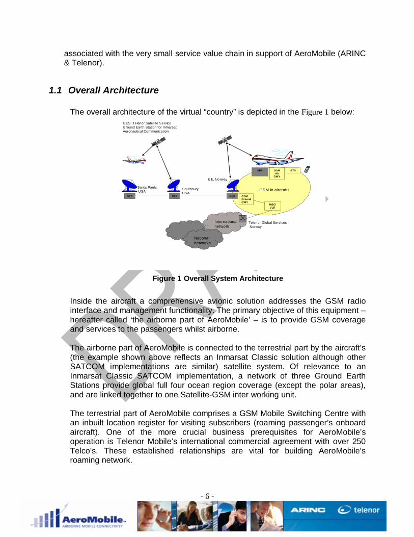
The overall architecture of the virtual “country” is depicted in the Figure 1 below:
MSC/VLR
GSMGroundGWY
GESGESGES
AES GSMAir
GWY
BTS
Eik, Norway
Southbury,USA
Santa Paula,USA
Internationalnetwork
Nationalnetworks
Telenor Global ServicesNorway
GSM in aircrafts
GES: Telenor Satellite ServiceGround Earth Station for InmarsatAeronautical Communication
Figure 1 Overall System Architecture
Inside the aircraft a comprehensive avionic solution addresses the GSM radiointerface and management functionality. The primary objective of this equipment –hereafter called ‘the airborne part of AeroMobile’ – is to provide GSM coverageand services to the passengers whilst airborne.
The airborne part of AeroMobile is connected to the terrestrial part by the aircraft’s(the example shown above reflects an Inmarsat Classic solution although otherSATCOM implementations are similar) satellite system. Of relevance to anInmarsat Classic SATCOM implementation, a network of three Ground EarthStations provide global full four ocean region coverage (except the polar areas),and are linked together to one Satellite-GSM inter working unit.
The terrestrial part of AeroMobile comprises a GSM Mobile Switching Centre withan inbuilt location register for visiting subscribers (roaming passenger’s onboardaircraft). One of the more crucial business prerequisites for AeroMobile’soperation is Telenor Mobile’s international commercial agreement with over 250Telco’s. These established relationships are vital for building AeroMobile’sroaming network.

- 7 -
The airborne service will be offered in the 1800 and or 1900 MHz bands only, notin the 900 and 850 MHz band. This will not cause an operation problem as circa.99% of GSM phones that are produced today are dual band capable permittinguninhibited roaming across both frequency bands.

- 8 -
2 AeroMobile System and Avionics Overview
The following section provides a technical overview of AeroMobile and touches onsome of the technologies that make our product possible.
The solution has been designed to operate over Aero H, H+ or I, Swift64,SwiftBroadband and Ku band initiatives.
The proposed solution will offer the following levels of functionality:
Ø Full duplex voice and text messaging support for GSM phones capableof operating within the 1800 MHz / 1900MHz GSM frequency bands.
Ø GPRS and related services i.e. MMS, EMS, picture messaging, emailetc (when utilizing Swift 64 or a broadband IP SATCOM).
Ø Supplementary services (TBC)Ø Prepay services (TBC)Ø RF Management of all phone technologies. GSM is supported from a
service perspective at a phones minimum power level. Othertechnologies are supported from an RF management perspective toensure possible interfering effects are mitigated.
Ø Service level control via the Crew Control Panel which gives the cabincrew the ability to vary the service level on board the aircraft shouldaircraft operation requirements dictate.This will include, but not be limited to:
o Ability to disable voice service allowing text only capabilities.o Disable solution completely – whilst still managing phones that
may still be switched on.o Show the number of attached phoneso Split VIP/Crew and Passenger Services

- 9 -
As shown in Figure 2 the on-board solution will generically comprise a number of keyelements:
1800MHz GSM Pico Cell
Cabin Crew Control Panel
SwiftBroadband
Classic Inmarsat
Ku band
Cellphone RF Management Units
Antenna (“leaky” feeder)Ethernet
Connections
Aerial Combiner Unit
4 MCU Avionic Server
1800MHz GSM Pico Cell
Cabin Crew Control Panel
SwiftBroadband
Classic Inmarsat
Ku band
Cellphone RF Management Units
Antenna (“leaky” feeder)Ethernet
Connections
Aerial Combiner Unit
4 MCU Avionic Server
Figure 2 Avionics Architecture
Hardware Components:
• Avionics Server• Control Panel• CRFMU (Cellphone RF Management Unit) * 2• BTSRFU (Base Transceiver Station Radio Frequency Unit)• ACU (Antenna Combining Unit)• Antenna• System Installation
2.1 Avionics Server
The Avionics server hosts three core AeroMobile software applications as described inSection 3 with the interfaces to the aircraft existing and future SATCOM systems viaeither CEPT E1 or Ethernet. The CRFMU and BTSRFU are connected directly to theserver via a Ethernet connection such that all the control and management is carried outover TCP/IP.

- 10 -
The Avionics server is a computing platform designed specifically for rugged airborneapplications. It utilizes various operating systems including: Microsoft Windows® aswell as Red Hat Linux. The Server is made up of the following subassemblies: SingleBoard Computer, one fixed EIDE isolated hard disk drive, AC or DC power supply withbackup battery pack, four separate and unique network interface controllers (NIC),providing two10/100BaseT Ethernet ports and two 1000BaseT Ethernet ports, a fourport Ethernet unmanaged switch, general purpose avionic discrete lines, VGA port, twoUSB ports, one RS232/485 serial interface port, CEPT-E1 and ARINC 429 interfaces,and a DSP Coprocessor. With the exception of the maintenance ports, virtually all I/Oand power lines are routed to the Server ARINC 600. Type II input/output (I/O)connector located on the rear of the 4MCU enclosure.
Further information on the server may be found in Appendix D.
2.2 Crew Control Panel
The Crew Control panel will be located within the aircraft cabin allowing cabin crew theability to control / monitor AeroMobile service levels and maintenance services asrequired.
The full extent of the maintenance panel’s capability includes:
• Monitor mobile phone usage during flight. At any instant in time cabin crewwill be able to confirm how many calls are active, phones connected to thesystem, text messages sent / received.
• Check the built-in test state of the system. AeroMobile system BIT data isaccessible from the control panel allowing detailed analysis of allAeroMobile systems and subsystems.
• Manage service levels in flight i.e. SMS / voice only services. This willallow the cabin crew to differentiate between night and day flights asappropriate.
• Switch system on and off.• Register cabin crew phones and give them priority and different service
levels to passenger phones.
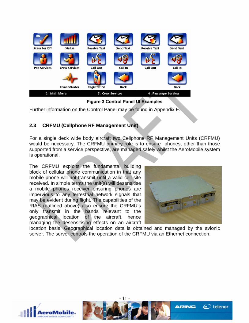
Figure 3 shows a number of UI screens displayed to the user.
- 11 -
Figure 3 Control Panel UI Examples
Further information on the Control Panel may be found in Appendix E.
2.3 CRFMU (Cellphone RF Management Unit)
For a single deck wide body aircraft two Cellphone RF Management Units (CRFMU)would be necessary. The CRFMU primary role is to ensure phones, other than thosesupported from a service perspective, are managed safely whilst the AeroMobile systemis operational.
The CRFMU exploits the fundamental buildingblock of cellular phone communication in that anymobile phone will not transmit until a valid cell sitereceived. In simple terms the unit(s) will desensitisea mobile phones receiver ensuring phones areimpervious to any terrestrial network signals thatmay be evident during flight. The capabilities of theRIAS (outlined above) also ensure the CRFMU’sonly transmit in the bands relevant to thegeographical location of the aircraft, hencemanaging the desensitising effects on an aircraftlocation basis. Geographical location data is obtained and managed by the avionicserver. The server controls the operation of the CRFMU via an Ethernet connection.

- 12 -
The CRFMU comprised of a single digital card thatperforms the functionality of a stored waveformgenerator. The digital card can be programmedfrom the Server to generate pre-determinedwaveforms for each of the cellular bands. TheCRFMU has four RF cards, 450MHz, 800/900MHz,1800/1900MHz and 2100MHz. The CRFMU canbe programmed to generate waveforms with aprogrammable start and stop frequency in thecellular bands as defined in Appendix B frequencychart. AeroMobile has patented the technique ofusing a swept modulated carrier that gives better performance at restricting the cellularsignal that a noise source and produces less peak to mean and is more effective
Further information on the CRFMU’s may be found in Appendix B.
2.4 Pico Cell (BTSRFU)All mobile phones have two things in common, that is (a) their power output variesdepending on the distance from the nearest cell site and (b) they will not transmit if theydo not detect a base station.
When the phone is first switched on it is the initial negotiation between the phone andcell site that dictates what power level the phone will transmit. In the context ofAeroMobile the cell site functions will be fulfilled by a cabin located base station(technically know as a Base Transceiver Station RF Unit (BTSRFU)). The terrestrialequivalent would be a cell tower. The base station will control operation of the phonessuch that MS power levels are limited to a very low level, typically (0dBm or 1mW).
The BTSRFU(s) initially provide the GSM 1800 / GSM 1900transceiver functions (other technologies will be supportedin the future ). The COTS based technology (shown right)represents the smallest and most cost-effective packageavailable today. Its low power and unobtrusive designdictates convenient installations above aircraft ceilingpanels or within the Passenger Service Unit.
To transition the COTS (Commercial Off the Shelf) BTS to anavionic standard LRU dictates a number of steps. Initially theCOTS product is converted into a ruggedised module (shownleft). The fit and form factor of this module has been carefullyconsidered to ensure future technology upgrades (3g, CDMAetc) can be accommodated within the existing module footprint.

- 13 -
This “module” is then located into an LRU housing (shownright), along with a PSU to complete the final BTSRFU LRUassembly
Each BTSRFU is capable of supporting up to 15simultaneous (satellite bandwidth permitting) calls andsafely managing the power levels of all the passengers’compatible GSM mobile phones. GPRS and text messagingservices are also supported by each BTSRFU, off aircraft bandwidth permitting.
Multiple BTSRFU LRU’s may be linked together to support greater call capacities as offaircraft bandwidth dictates. More technical information regarding the BTSRFU may befound in Appendix A.
2.5 Antenna Combining UnitThe CRFMU’s and BTSRFU components all have RF output components that need tobe combined and distributed across a single cabin antenna solution in a manor suchthat no inter modulation products are produced that would generate significant signalsto affect the AeroMobile system operation or the operation of the aircraft.
The ACU is designed to take up to two 1800MHz BTSRFU, two 1900MHz BTSRFU, twoCRFMU (for diversity and redundancy) and a single WiFi AP.
The ACU comprises of two 1800MHz diplexers, two 1900MHz diplexers, a three-bandduplexer and a cross band coupler.
Further information on the ACU may be found in Appendix C.
2.6 Antenna SystemIn order to reduce the fading within the cabin AeroMobile utilises two leaky feedercables separated by at least one metre in the cabin. Each leaky feeder is fedindependently with a single CRFMU producing two CRFMU signals that are noncoherent and reduce the fading margin required within the cabin to protect the a-MSfrom receiving a signal from the ground network. This method is patent pendingAeroMobile along with the signal generation in the CRFMU.

- 14 -
2.7 System Installation
It is clearly understood that airlines run a high utilisation factor so aircraft down time iskept to an absolute minimum. Accordingly it is envisaged the solution will be installedduring routine maintenance down time not requiring any unscheduled aircraft out ofservice down time. Figure 4 below provides a level of clarity as to the proposedlocations of the AeroMobile LRU’s on a wide body aircraft.
Control Panel in VCC &Kill Switch on flightdeck "Leaky Feeder" Cable
Flexible coaxial linkconnecting to leakyfeeder above door
Location of SATCOM rackand AeroMobile server(E11 rack)
BTS and CRFMU(Palette)
Location of IFE CTU(E12 Rack)
Figure 4 Example Installation
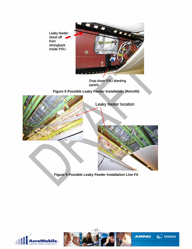
Two areas have been identified for the installation of the leaky feeder within the aircraftalready surveyed but each aircraft type needs to be reviewed for the types of materialsused in the construction of the aircraft interior. Figure 5and Figure 6 shows thepossible installation for retrofit and line fit based on the cabin materials. The installationalso needs to ensure that at least one metre between the two leaky feeder antennas toensure the diversity for the CRFMU operation to be effective.
- 15 -
Drop down PSU blankingpanels
Leaky feederstood offfromstrongbackinside PSU
Drop down PSU blankingpanels
Leaky feederstood offfromstrongbackinside PSU
Figure 5 Possible Leaky Feeder Installation (Retrofit)
Leaky feeder locationLeaky feeder location
Figure 6 Possible Leaky Feeder Installation Line Fit

- 16 -
3 AeroMobile Software Overview
The AeroMobile software comprises of three concurrent applications: Radio InterferenceAvoidance System, ControlServer and Mobile Sub-System as shown in Figure 7.
The communication between each application and the CRFMU and BTSRFU uses asocket based interface.
Section 3.1 describes at a high level the Mobile Sub-System Application and Section3.2 the RIAS.
Figure 7 AeroMobile Software Architecture

- 17 -
3.1 Mobile Sub-SystemThe Mobile Sub-system is the interface between the BTSRFU and the ground network.The MSS has a core application that includes some functionality of a BSC to minimisethe traffic over the SATCOM. This is a patent pending solution.
The Mobile Sub-system is the main application that modifies the existing GSM protocolsto and from the SATCOM system. The application has a number of patent pendingtechniques that minimise the SATCOM traffic and manage the on-board system withlittle or in fact no SATCOM traffic. The Mobile System is the interface to the BTSRFUwhich is controlled via a TCP/IP connection. The Mobile System can manage both1800 and 1900MHz BTSRFU’s when connected to the system.
Figure 8 shows the overall architecture of the MSS at a high level. The MSS cansupport a number of external software modules to support the different SATCOMsystems available to the aircraft. The initial application is the CEPT E1, which connectsto the existing Classic SATCOM systems currently flying in over 3000 of today’scommercial and general aviation aircraft.
AeroMobile has also publically demonstrated the Swift64 to support GPRS (andadditional voice capability using a patent pending technique) and will support early nextyear a total IP solution for IP SATCOM systems such as Connexion by Boeing andARINC’s SKYLink Ku solution.
Location Update Voice MO
Voice MT
SMS MO
SMS MT
TRAU
RIAS InterfaceSATCOMInterface
BSC
AltoBridge Application
GSM 04.08
GSM 08.58 GSM 12.21 IP AccessChannel Control
GSM 04.08 GSM 08.08 O&M
MF Gateway Protocol
TCP/IP & Ethernet
TRAU
BTS
X25Q931
CEPT E1
SwiftMPDS
Live IPRTP/SIP
SwiftISDN
Classic SATCOMSwift SATCOMSwiftbroadbandSATCOMLocation Update Voice MO
Voice MT
SMS MO
SMS MT
TRAU
RIAS InterfaceSATCOMInterface
BSC
AltoBridge Application
GSM 04.08
GSM 08.58 GSM 12.21 IP AccessChannel Control
GSM 04.08 GSM 08.08 O&M
MF Gateway Protocol
TCP/IP & Ethernet
TRAU
BTS
X25Q931
CEPT E1
SwiftMPDS
Live IPRTP/SIP
SwiftISDN
Classic SATCOMSwift SATCOMSwiftbroadbandSATCOM
Figure 8 MSS Architecture

- 18 -
3.2 Radio Interference Avoidance System
3.2.1 RIAS/ Control Server Input ParametersThe RIAS will have access to the following aircraft parameter via the ARINC 429interface from the FMC (Flight Maintenance Computer):
• Aircraft Mean Sea Level Altitude• Aircraft Speed• Aircraft Lat/Long• Heading• City/Airport Codes Pairs (departure and arrival)
3.2.1.1 Frequency Area (FA)The RIAS shall contain a database of frequencies for the a-BTS operation based on adatabase of ARFCN for the a-BTS and the CRFMU frequency bands called a ‘frequencyarea’ (FA) of the world (as defined in 3.2.9). ARFCN definition is defined in Appendix 2.Figure 2 shows an example of a ‘Frequency Area’ map for the world.
Figure 9 – Frequency Area Example
ARFCN 912 + Band 1,3
ARFCN +Band 0,2,3
ARFCN 3 + Band 0,2,3,4
ARFCN 4 + Band 0,2,3,4
ARFCN 5 +0,2,3,4
- 19 -
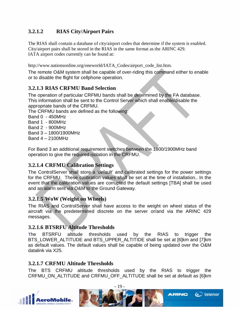
3.2.1.2 RIAS City/Airport Pairs
The RIAS shall contain a database of city/airport codes that determine if the system is enabled.City/airport pairs shall be stored in the RIAS in the same format as the ARINC 429.IATA airport codes currently can be found at:
http://www.nationsonline.org/oneworld/IATA_Codes/airport_code_list.htm.The remote O&M system shall be capable of over-riding this command either to enableor to disable the flight for cellphone operation.
3.2.1.3 RIAS CRFMU Band SelectionThe operation of particular CRFMU bands shall be determined by the FA database.This information shall be sent to the Control Server which shall enable/disable theappropriate bands of the CRFMU.The CRFMU bands are defined as the following:Band 0 - 450MHzBand 1 - 800MHzBand 2 - 900MHzBand 3 – 1800/1900MHzBand 4 – 2100MHz
For Band 3 an additional requirement switches between the 1800/1900MHz bandoperation to give the required isolation in the CRFMU.
3.2.1.4 CRFMU Calibration SettingsThe ControlServer shall store a ‘default’ and calibrated settings for the power settingsfor the CRFMU. These calibration values shall be set at the time of installation.. In theevent that the calibration values are corrupted the default settings [TBA] shall be usedand an alarm sent via O&M to the Ground Gateway.
3.2.1.5 WoW (Weight on Wheels)The RIAS and ControlServer shall have access to the weight on wheel status of theaircraft via the predetermined discrete on the server or/and via the ARINC 429messages.
3.2.1.6 BTSRFU Altitude ThresholdsThe BTSRFU altitude thresholds used by the RIAS to trigger theBTS_LOWER_ALTITUDE and BTS_UPPER_ALTITIDE shall be set at [6]km and [7]kmas default values. The default values shall be capable of being updated over the O&Mdatalink via X25.
3.2.1.7 CRFMU Altitude ThresholdsThe BTS CRFMU altitude thresholds used by the RIAS to trigger theCRFMU_ON_ALTITUDE and CRFMU_OFF_ALTITUDE shall be set at default as [6]km

- 20 -
and [6]km respectively. The default values shall be capable of being updated over theO&M datalink via X25.
3.2.1.8 3D GIS Database of the WorldThe RIAS shall contain a pre-processed elevation database of the world. The GISdatabase shall be such that at any point with a +/- [1km] precision on the earth surfacethe ‘averaged1’ height above MSL. This will allow the RIAS in conjunction with theARINC MSL data to determine the height above the ground.
3.2.1.9 ARFCN/CRFMU Frequency Area (FA) DatabaseThe RIAS should contain an overlay to 3.2.8 that includes a definition of each‘frequency area’ that can be defined offline.The RIAS software shall be capable of importing an Excel database [format CSV] thatrelates each ‘frequency area’ defined in 3.2.9.1. The Excel database should compriseof at least:Frequency Area Description, ARFCN, CRFMU Band, CRFMU Band Modification (e.g.different start stop).Offline pre-processing should ensure that each FA definition in both database areconsistent.The FA database should ideally be updateable remotely via O&M. Note: X25 limitations(e.g. bandwidth) should be considered here in any implementation.Note: The reason for the difference between countries and frequency area is that inparticular countries the licensing could be on a region of a country (e.g. Queensland)therefore ARFCN areas could be a subset of a country. The opposite is true in that a FAcould be defined as a continent (e.g. Europe).
3.2.2 BTS RIAS Requirements
3.2.2.1 BTSRFU Altitude ControlThe RIAS software needs to tell the ControlServer when the aircraft crosses the twoground Altitude thresholds BTS_LOW_ALTITIUDE and BTS_UPPER_ALTITIUDE. TheBTSRFU has to be turned on (green) / shutting down2 (yellow) and off (red) asrepresented on the Figure 10. The upper and lower threshold altitudes are separate andcan be configured remotely via the O&M interface.
1 By averaged it is intended to take average ground height averaged around the radio horizon of the aircraft(described in Section 4)2 Shutting down will still hold existing calls but not allow new calls to be established.

- 21 -
Figure 10 BTSRFU Altitude Management
3.2.2.2 BTSRFU ARFCN ControlThe Control Server shall be able to load a pre-determined ARFCN from the RIASdatabase based on the current FA.As the aircraft flies across each FA the RIAS shall inform the ControlServerapproximately [5] minutes prior to the aircraft reaching the FA border (be that between‘frequency areas’ or to the coast) with a BORDER_WARNING (ARFCN, BANDS). TheControl Server shall load the ARFCN into the BCCH as a surrounding cell in preparationfor the ARFCN frequency change.
3.2.2.3 Contiguous-FAWhen the aircraft crosses a border between two (or more) adjacent FA the ControlServer will receive a BORDER_HARD_TUNE indication from the RIAS and immediatelyretune the BTS and simultaneously re-program the CRFMU (see Section xx) bands andre-tune the BTS notch according to the ARFCN parameter sent in the earlierBORDER_WARNING message. If the borders are closer together then theBORDER_WARNING to BORDER_HARD_TUNE will be less than the [5] min. It isimportant that the BCCH does contain the updated ARFCN for at least [1] min to ensurethat the a-MS does not go into a search
3.2.2.4 Ocean Separated-FAIf the aircraft flys from one FA to another over the ocean then the AeroMobile systemwill try and minimise the effects on the a-BTS retune to the end users. The RIAS shallsend the same BORDER_WARNING (ARFCN, BANDS) [5] minutes prior to the aircraftreaching the next FA border and load the BCCH with the ARFCN as a surrounding cell.However rather than the RIAS sending BORDER_HARD_TUNE the RIAS shall sendBORDER_SOFT_TUNE immediately after the BORDER_WARNING but only if theRIAS has determined that the aircraft is over the ocean. The Control Server shall then

- 22 -
(1) Load the ARFCN into the BCCH for at least [1] minute, (2) wait until the BTS has noactivity before ‘soft’ retuning to the new ARFCN (reducing the effects on the passengerservice) or (3) in the event that the reaches the next AF border (indicated by the RIASsending BORDER_HARD_TUNE) the ControlServer will initiate a ‘hard’ retune when itcrosses the border (all traffic will be lost).
3.2.2.5 Flight route lock downThe RIAS will have to read the ARINC 429 words that correspond to the departure andarrival cities.In the event that the city pairs are NOT available then the system should be lockeddown from system activation.Based on the cities pairs the system needs to be able to lock down the whole systemfrom activation.For example, DUBAI to SYDNEY is allowed but DUBAI to LONDON is locked down.
3.2.2.6 System deactivation messageThe RIAS needs to inform the Mobile Subsystem via the Control Server that the servicewill be turned off. The time between sending this message and the deactivation of thesystem needs to be configurable on the remote gateway(DEACTIVATION_MSG_TIME).

- 23 -
3.2.3 CRFMU RIAS RequirementsThe CRFMU (NCU) will be controlled by the aircraft ground altitude and ARFCNborders.
3.2.3.1 AltitudeReferring to Figure 11 the RIAS shall inform Control Server with the aircraft is equal toor greater than the CRFMU_ON_ALTITUDE and also when the aircraft descends belowthe CRFMU_OFF_ALTITUDE.
Figure 11 CRFMU Altitude Thresholds
3.2.3.2 CRFMU Band ControlAs the aircraft flies across FA the RIAS shall inform the ControlServer at least [5]minutes prior to the aircraft reaching the FA border (be that between FA’s or from oneFA to the coast) with a BORDER_WARNING (ARFCN, BANDS).
3.2.3.3 Contiguous-FAWhen the aircraft crosses a ARFCN border between two (or more) adjacent FA theControl Server will receive a BORDER_HARD_TUNE indication from the RIAS andimmediately retune the BTS (as in Section 3.3.2.1) and simultaneously re-program theCRFMU bands along with the appropriate LUT (Look Up Table) for the BTSRFUARFCN. If the borders are closer together then the BORDER_WARNING toBORDER_HARD_TUNE will be less than the [5] min.
3.2.3.4 Ocean Separated-FAIf the aircraft flys from one FA to another over the ocean then the AeroMobile systemwill try and minimise the effects on the a-BTS retune to the end users. The RIAS shall

- 24 -
send the same BORDER_WARNING (ARFCN, BANDS) [5] minutes prior to the aircraftreaching the next FA border and load the BCCH with the ARFCN as a surrounding cell.However rather than the RIAS sending BORDER_HARD_TUNE the RIAS shall sendBORDER_SOFT_TUNE immediately after the BORDER_WARNING but only if theRIAS has determined that the aircraft is over the ocean. The Control Server shall then(1) Load the ARFCN into the BCCH for at least [1] minute, (2) wait until the BTS has noactivity before ‘soft’ retuning to the new ARFCN (reducing the effects on the passengerservice) or (3) in the event that the reaches the next AF border (indicated by the RIASsending BORDER_HARD_TUNE) the ControlServer will initiate a ‘hard’ retune when itcrosses the border (all traffic will be lost).
3.2.3.5 Flight route lock downThe RIAS will have to read the ARINC 429 words that correspond to the departure andarrival cities.In the event that the city pairs are NOT available then the CRFMU system should belocked down from system activation.Based on the cities pairs the system needs to be able to lock down the whole systemfrom activation.For example, DUBAI to SYDNEY is allowed but DUBAI to LONDON is locked down.
3.2.3.6 System deactivation messageThe RIAS needs to inform the Mobile Subsystem via the Control Server that the servicewill be turned off. The time between sending this message and the deactivation of thesystem needs to be configurable on the remote gateway(DEACTIVATION_MSG_TIME).

- 25 -
4 AeroMobile Ground Infrastructure Overview
The AeroMobile system leverages the existing SATCOM infrastructure of TelenorSatellite Services (TSS) and the Mobile infrastructure of Telenor Mobile.
A single POP with two Ground Gateways support up to 300 aircraft and are connectedat to the global TSS architecture in Norway. All MO/MT calls made are routed via theGround Gateway in Eik where they are covered back into the standard ‘A’ interface andconnected to the Telenor MSC as shown in Figure 12. The software in the GroundGateway completes the balance of the BSC functionality carried out on the Mobile Sub-System aircraft application such that the MSC is completely unaware that the BSCfunctionality is distributed between the ground and the aircraft.The each Ground Gateway server is built on high reliability COTS servers that providethe necessary reliability requirements for a mobile service. Figure 13 shows one of thedeployed Ground Gateways.The AeroMobile Ground Gateway is also connected via ISDN and the Internet tosupport both Swift 64 and IP SATCOM system.The Ground Gateways have been fully integrated into the TSS SATCOM infrastructureand testing competed globally from land and a recent 777-200LR flight trial that initiallyflew around the world and then completed the longest commercial flight from HongKong to London.A third Ground Gateway is deployed in Grimstad (Norway) for roaming and billingtesting.

- 26 -
ISDNPSTNSS7
AeroSBY
AeroEIK
AeroSPA
DatapakX-25
SS7Santa Paula
SS7EikSS7
Southbury
ArincX-25
TelenorMSC
R1 (A,B,XX,CC) R1 (A,B,XX,CC) R2D (B)
X-75
SS7 SS7 SS7
X-75 (D3, CC)X-25(D2/3)
X-75D2/3
X-75 (D2/3)
Euro-ISDN Q931
(alt. ISUP)
Gournd AeroGSMGWEik
X-25
ISDNPSTNSS7
ISDNPSTNSS7
AeroSBYAeroSBY
AeroEIKAeroEIK
AeroSPAAeroSPA
DatapakX-25
DatapakX-25
SS7Santa PaulaSS7Santa Paula
SS7EikSS7EikSS7
SouthburySS7Southbury
ArincX-25ArincX-25
TelenorMSC
TelenorMSC
R1 (A,B,XX,CC) R1 (A,B,XX,CC) R2D (B)
X-75
SS7 SS7 SS7
X-75 (D3, CC)X-25(D2/3)
X-75D2/3
X-75 (D2/3)
Euro-ISDN Q931
(alt. ISUP)
Gournd AeroGSMGWEik
Gournd AeroGSMGWEik
X-25
Figure 12 AeroMobile Ground Infrastructure
AeroMobileGround Gateway
AeroMobileX25 IP Gateway
Figure 13 AeroMobile Ground Gateway

- 27 -
5 Certification
5.1 Introduction
Certification of the onboard avionic equipment is clearly different from theregulatory processes. The ‘Chicago convention’ outlines that the authorities of thecountry in which an aircraft has been registered have to certify and be accountablefor every piece of communications equipment that will be installed within an aircraft.This agreement applies as a general principle. However, the governments in thedifferent countries may put different agencies in charge of the enforcement. Indeedit is the aviation authorities such as the FAA and EASA that traditionally managethese processes.
In current practice, permanently installed aircraft equipment is usually qualified toan environmental standard such as RTCA DO-160. Avionic equipment, includingtransmitters, generally complies with the additional requirements imposed by arelevant Minimum Operational Performance Standard (MOPS) or TechnicalStandard Order (TSO). The responsibility for maintenance, replacement, andperiodic verification of performance rests resides with the aircraft operator.
Products in the consumer marketplace are not subject to the same stringentenvironmental requirements as avionic systems. Once sold to the consumer, theyare no longer subject to effective controls regarding their use or maintenance. Amobile phone solution clearly challenges this philosophy.
Suspected Electro Magnetic Interference (EMI) from mobile phones aboard aircraftis a popular subject for mass media reporting. Although some of these reportsare misleading they have aided the airline industry in passenger educationregarding the potential risk of mobile phones during flight and, to a certain extent,have helped the public to better understand the FAR 91.21 safety announcementsegment prior to each flight. Conversely, a perceived lack of substantivepublished and publicly available mobile-aboard-aircraft EMI reports contributes toscepticism regarding limitations to on-board use.
There have been reported incidents where pilots initially attributed aircraftsystem anomalies to mobile phone interference, but after further evaluation afault condition was discovered in a specific airplane system. However, there havealso been reports of on-board interference that has simply “gone away” whensome devices have been turned off. Even studies conducted by the UK CAA ,NASA, ERA, Boeing, Lufthansa, and US Airways lead to contradictoryconclusions if the contexts of the studies are not fully taken into account.
However, over the last 18 months a number of significant industry bodies haverecognised that the use of phones on board aircraft is fast becoming reality and

- 28 -
have commissioned research to investigate the supporting issues and offercertification guidelines.
Significantly the United States Federal Aviation Administration (FAA) haverequested that the RTCA, Inc. form a special committee (Steering Committee202) to present an up-to-date evaluation of the use of portable electronic devices(PEDs) on board civil aircraft with emphasis on intentional transmitters suchas mobile phones, wireless RF network devices, and other wireless-enableddevices such as personal digital assistants (PDAs). For the purpose of claritythese devices are referred to as transmitting PEDs, or “ T-PEDs” , as distinct fromnon-transmitting PEDs, such as compact disk players and calculators. The overallclass of PEDs includes both T-PEDs and the traditional non-transmitting PEDs.
The committee includes representatives from consumer electronic devicemanufacturers, avionics manufacturers, aircraft manufacturers, airlines, aircraftoperators, pilots, flight attendants, regulatory agencies, and relatedindustry associations. The committee works closely with other industry groupssuch as the Consumer Electronics Association. This work has also beencoordinated within the European EUROCAE Working Group 58.
One goal of the SC202 working group is to provide guidance to those who wish toallow the use of intentional transmitters on board aircraft within their fleet. Previousapproaches to allowing T-PED usage by Lufthansa Technik as well as testingperformed by various CAA organizations, NASA, Boeing, and US Airways, wereinstrumental as starting-points in the development of the guideline.
The work of SC202 has been broken in to two main areas:
1) Guidance on Allowing Transmitting Portable Electronic Devices (T-PEDs) on Aircraft.
2) Guidance on allowing use of PICO cell technologies onboard aircraft.
Part one has been completed and is now in the public domain for review. Part twowas started in October 2004 with draft guidelines tentatively due for publication in2006.
AeroMobile is an active member of this consortium and certainly supporting all aspects ofwhat this group stands for.
5.2 Retrofit Certification Strategy
As referenced above the output of RTCA SC202 is due to conclude late 2006.Recognising that AeroMobile will be certifying cell phone systems on boardaircraft prior to this date a number of supplementary activities are beingundertaken. Certification processes dictate that an EASA / FAA approvedmodification house start the STC process with an application to EASA or theFAA. This application would typically cite the aircraft tail number in question andoutline the scope of the modification.

- 29 -
Historically the certification house would then respond with an “issue” paperoutlining the necessary steps to ensure safe embodiment of the requiredmodification. Until the FAA guidelines for cell phone certification have beenpublished it is fully expected that the respective certification bodies would holdany application until the SC202 guidelines are available. This would allow therelease of an “issue” paper to the mod house.
To alleviate the above challenges AeroMobile are engaged in a number ofsupplementary activities that will ultimately define how we plan to certify aAirbus and Boeing aircraft in a retro fit environment. This strategy has beenpresented to both the FAA and EASA with a positive outcome.
Fundamentally AeroMobile has contracted the support of a specialist third partyorganisation majoring in EMI and risk / safety management. These bodies areassisting AeroMobile in the formation of a credible & coherent strategy thatdemonstrates practicable measures have been taken in our solution designaddressing safety and non-interference issues relative to a given aircraft avioniccompliment. Much of this data will form part of any aircraft modificationapplication to FAA and or EASA.
This strategy, and resultant paper, will fully embrace:
5.2.1 Independent Safety Advice
Provided throughout the development programme cycle to ensure the avionicsolution is designed for safety.
5.2.2 Safety Management Plan Development and Management
Formation of an approved Safety Management Plan. The Safety Plan willinclude the Strategic Compliance Strategy, in which a strategy for ensuringappropriate provision for:
• Assessment• Demonstrating Compliance• Mitigation• Remediation.
5.2.3 AeroMobile Safety Group
Formation of a suitable Safety Management Organisation, “dove tailing” withexisting ARINC QA procedures. Management of the Safety Group meetings willbe independently conducted to ensure validation of the safety activities andprocesses.
The Safety Group meets every 6 weeks, where a 3rd party is responsible forpost group activities such as updating;

- 30 -
• Hazard Log status.• Safety Case validity, including both argument and evidence.• Safety Management Plan.
5.2.4 Safety Management System (SMS)
Development of a formal Safety Management System (SMS) for the project inaccordance with the provisions of ARP 4754. The SMS will define the:
a. AeroMobile Safety Organisation
b. Establish the baseline level of safety for the system, including all systemsand assets associated with service provision based on a sound anddefensible Safety Case.
c. Provide for the continued management of the system through the:
§ Identification of hazards firstly to AeroMobile operation and,subsequently to all of it’s subsystems.
§ To encourage removal of hazards by design and if this is notpossible then to ensure that the risks associated with them arereduced to ALARP by design change or through the introduction ofcontrol measures (e.g. check procedures, specific warnings,mandatory maintenance requirements, imposition of operatinglimits).
§ Implementation of an audit programme and the undertaking ofregular audits to ensure compliance. This will:
o establish a mechanism to allow failures to be reported andacted upon.
o establish and oversee development and maintenance of theSafety Case.
o To continually improve the level of safety and ensure thatwherever possible all hazards are received and maintainedat ALARP throughout the life of AeroMobile.
5.2.5 HAZOP Study
HAZOP will be used as a preventative hazard identification process to ensureand facilitate early hazard identification and management.

- 31 -
5.2.6 Hazard Log
Formation of a Hazard Log, for the Risk Reduction phase of development.
5.2.7 Risk Assessment
Formation of a safety compliance criteria based on the baseline systemdescription. System design criteria will be assessed against qualitativeanalyses carried out in the hazard analysis programmes. Quantitative analysiswill be used to assess high safety critical functions where qualitative methodsare inadequate to demonstrate the safety of the system under assessment.
The Risk Assessment will include the provision of measures to ensure RiskMitigation and Risk Acceptance
5.2.8 Safety Requirements
Detailed Safety Requirements will be derived from the hazard identification andrisk assessment process. These will be input to the Accident Model enablingthe application of safety targets to sub-systems and to show that the systemhazards are controlled and meet the Top Level Safety Targets for the service.
5.2.9 Accident Model Development and Management
Formation of an Accident Model in Fault Tree Plus detailing the relationshipbetween accidents and the hazards that lead to them. The accident model willensure compliance with current safety targets.
5.2.10 Failure Mode Effects Analysis
Having identified the top-level hazards, a detailed assessment will be carriedout to focus on every part of the system design. The aim will be to identifyways in which the system could deviate from its design intention. The FMEAwill examine both hardware and software failures, identifying mitigation andsafeguards, which will provide a degree of protection against the hazard leadingto the associated accidents. The impact of all failures will be assessed todetermine their level of criticality enabling identification of the relationshipbetween specific failures and the hazards to which they may contribute. Thiswill enable the likelihood of occurrence of the identified hazards to be quantified.
Where appropriate, these results will also be used to guide the preparation ofthe electromagnetic EM test plans.
- 32 -
The detailed assessment and FMEA work will draw on previous workundertaken by EUROCAE and RTCA to determine ways in which a mobilephone failure could lead to a system hazard. The FMEA will draw onpreviously undertaken analysis and assessments and will bounded by a set ofassumptions at the start of the project.
5.2.11 Software Assurance
Following results of the safety review, a Development Assurance Level will beset, based on the criticality of the hazards which can arise as a result of asoftware failure.
5.2.12 Safety Case
A Safety Case will be developed for AeroMobile for presentation to the FAA andor EASA, which will demonstrate a structured, sound and defensible argumentthat will take the form of a report referencing all of the evidence. The SafetyCase will make reference to objective evidence that comes in many formsincluding:
• Plans• Requirements• Test results• Analysis reports• Hazard Log etc.• System Description in the form of one or more configuration
baselines.• A definition of “Safe”, which in this case is the JAR 25 definition.
The Safety Case report will provide a structured argument detailing:
• How safety was managed including reference to the SMP• The safety standards that the service complies with or a validated
explanation or justification in the event of a non compliance• A record of all assumptions made.• Assurance that the risk of all hazards has been reduced ALARP• Assurances that all identified safety requirements have been
achieved• Evidence supporting that specific configuration and baseline service
installations have been successfully tested, safety assessments havebeen completed and that equipment integration issues have beenadequately addressed.
• Evidence to show that items in the issue log are closed
5.2.13 EMC
The primary objective of the EMC task will be to develop an acceptable EMCtest and assessment strategy which is required for AeroMobile system to be

- 33 -
used onboard aircraft.

- 34 -
6 Appendix A - BTSRFU (A6129665000-1/2 and A6129666000-1) Outline Spec
The BTSRFU, or nanoBTS as the COTS product isknown, represents the smallest and most cost effectivepackage available today. It’s use of IP for backhaulensures compatibility with current and futureSATCOM / cabin architectures. The product has beendeveloped in accordance with ETSI standards,guaranteeing compatibility with current and plannedmobile phones.
The BTSRFU is a complete GSM base station thatconforms to the ETSI 12.21 BTS standard. TheBTSRFU uses a variation of the standard Abis interface, but carried over IP so that it can beconnected back over a wide variety of off aircraft SATCOM technologies.
Several varieties of BTSRFU areavailable, permitting operation inthe 1800MHz band (A612966500-1)and 1900MHz (A612966600-1) PCSfrequency bands. Independentlyeach BTSRFU can support up toseven simultaneous calls (inc theBCCH) or if chained together cansupport 15 calls and a single BCCHsignalling channel. For EDGE andAMR compatibility a BTSRFUvariant is available (A6129665000-2). This allows the number of callsper BTSRFU to increase to 15calls(assuming AMT compatible phones)and also allows Enhanced Data forGSM Evolution offering theoretical
data rates up to 384kbps. For aircraft that require to fly over CONUS and the ROW a dual1800MHz / 1900MHz installation is recommended. The RIAS will automatically switch fromone band to the other determined by the aircraft position.
As cellular technologies evolve so must the technology onboard the aircraft with the AeroMobilearchitecture it is possible to add a BTS that supports UMTS or/and CDMA technologies.
COTSnano BTS
115V 400/60//50Hz
+28VDC
Power Supply
Ethe
rnet
PowerSupply
Battery /Capacitor
RXAntenna
TXAntenna
BTS RFU Avionics LRU -1 (1800MHz) / -2 (1900MHz)
+48VDC
115V- 50/60/400Hz
+28VDC
Disable (1)
Disable (2)RFU Status
Indicator
PowerSupply Status
BTS Sync In BTS Sync Out
+5VDC
"Ruggedised" BTS Module
10MHz Test Output Aircraft Protection / Buffering and
Ethernet Switch
10MHz Test Input
Supply andDiscretes
EthernetEthernet

- 35 -
Radio Interface
Model GSM 1800 GSM 1900Transmit frequencies 1805-1880MHz 1930-1990MHzChannel spacing 200kHz 200kHzMax. output power +23dBm +23dBmRX Sensitivity (typical) -106dBm -106dBmOutput power control 12 steps 12 stepsReceive frequencies 1710-1785MHz 1850-1910MHzChannel spacing 200kHz 200kHzPerformance GSM 05:05 GSM 05:05Receive gain control 26 steps 26 steps
Services SupportedVoice - GSM FR and EFR, AMR (TCH_AFS and TCH_AHS)Short Message ServiceGPRS / E GPRS
Channel Support
Each BTSRFU (A6129665000-1 / AA612966600-1) support a single TRX (0 – 7 voice calls) theEDGE variant (A6129665000-2) can support up to 14 voice calls.
Up to 4 BTSRFU (of different variants) can be connected to a single ACU to provide expansionand data capabilities as the SATCOM system permits.
PhysicalTwo D Type ConnectorsTwo Ethernet 10/100 connectionsTwo Enable/Disable DiscretesTiming Interface Bus (TIB) providing BTSRFU interconnect for multi-TRX functionalityTwo SMA connectors BTSRFU transmit BTSRFU receive
Dimensions & weightHeight: 41.4mmWidth: 292mmDepth: 206.5mmWeight: Circa. 2.8Kg
Power115V, 400/60/50Hz

- 36 -
Standards
Ruggedised 1800MHz BTS Module: CE Marked EN 60950-1 EN 301-489-1 and -8
EN 301 – 502 GSM 11.21 essential compliance3
Ruggedised 1900MHz BTS Module: FCC 47CFR part 24 GSM 11.21 essential compliance
LRU qualified to D0-160E / BCAG D6-36440 / Airbus ABD100
MountingARINC 763 type mounting
MTBF Circa 20,000hrs
3 Relaxing of the phase noise from 5 degrees to 7 degrees.

- 37 -

- 38 -
7 Appendix B - CRFMU (A6129664000-1 and -2) Outline Spec
The Cellphone RF ManagementUnit’s (CRFMU), shown left, arean integral part of AeroMobile’scabin antenna system. The CRFMUshares the same leaky feeder cabinantenna as the BTSRFU andproduces swept RF signalscovering each downlink (base-station to mobile) cellularfrequency band used in the area theplane is flying over. The signalsgenerated by the CRFMU block themobile from receiving terrestrial
base-station signals effectively ensuring the mobile on board the aircraft can only useAeroMobile services on board the aircraft. An initial unit excluding the 450MHz band hasbeen deveopled AA6129664000-1 and the production unit AA6129664000-2 with the450MHz band which represents the production version.
The CFRMU consists of a core CFRMU RF modulewith supporting power supplies, Ethernet switch, and thebuffering and protection circuits specifically needed forsystems used on aircraft.
The core CRFMU RFmodule will consist ofa common interfacePCB providing powerdistribution, control andexternal interface functions, together with three RF units.Each RF unit will consist of a signal generator and poweramplifier. Each unit fit’s into a separate EMC screenedcompartment within the LRU enclosure to ensure there isadequate isolation between each generator. Provision will bemade for a fourth RF unit to allow for future expansion of thesystem. This architecture is shown right.
The system enclosure serves as a heat sink for the power amplifier and other heat dissipatingcomponents with the aim of avoiding local ‘hot spots’ and minimising the temperaturerise above ambient. A simple, high reliability connector system is used to connect each RFunit to the interface PCB. This will allow the interface PCB to provide control and power to

- 39 -
each RF unit with the RF unit returning key status information such as correct synthesiserand power amplifier operation and over-temperature warning.
Radio Interface
CRFMU Frequency BandsThe CRFMU covers the major cellular bands as defined in Figure X.
1.1

- 40 -
The CRFMU shall encompass the following bands and power levels as defined in Table X to Y
PCB 1:Description Band Lower
BandEdge
[MHz]
UpperBandEdge
[MHz]
MaxPower(dBm)
GSM 1800 / UMTS Band III 2 1805 1880Korean PCS / CDMA Class 4 2 1840 1870GSM 1900 / CDMA Class 1 2 1930 1960NA PCS 2 1930 1990
PCB 2:Description Band Lower
BandEdge
[MHz]
UpperBandEdge
[MHz]
MaxPower(dBm)
CDMA 450 4
PCB 3:Description Band Lower
BandEdge
[MHz]
UpperBandEdge
[MHz]
MaxPower(dBm)
IMTS-2000 3 2110 2170
PCB 4:Description Band Lower
BandEdge
[MHz]
UpperBandEdge
[MHz]
MaxPower(dBm)
iDEN 1 806 824 28Japan TACS 1 832 870 28AMPS/DAMPS/NAMPS/UMTS BandV 1 869 894 28TACS 1 917 960 28GSM-R / GSM 900 1 915 960 28GSM 900 1 925 960 28JDC 1 940 956 28
The power in each band shall be adjustable in ten steps of 2dB (TBC) down from the maximumpower. The tolerance on power levels shall not exceed ±1dB (TBC) at maximum power setting.

- 41 -
Waveform Description
The signal in each band shall take the form of a chirp, i.e. a swept frequency waveform. Theeffective sweep waveform shall be a “sawtooth” triangular wave as indicated in Figure 14.
5us or 20us
MaximumFrequency
MinimumFrequency
Figure 14 Frequency Sweep Waveform
The sweep shall repeat at a rate of either 50kHz or 200kHz. This repeat rate is the same as thechannel frequency width for each mobile phone. The frequency range used for each phone willbe called a ‘channel in this specification. There will be a maximum of 800 values set for eachramp.
The maximum and minimum frequencies will be programmable, with a maximum sweptbandwidth of 75MHz.
The two CRFMUs operating on the aircraft at the same time will have a dither induced by arandom “M sequence” to ensure that both signals are non-coherent . A “windowing” techniquewill be used to minimise the out of band emissions and improve in band flatness. This requiresthe amplitude of the chirp signal to be slightly smaller (and tapered) for the extreme frequencies.
The simple sinusoidal chirp signal of constant amplitude will generate signals in every channelof the swept bandwidth. By modulating the amplitude and phase of that signal, a ‘notch’ in thespectrum can be produced. Within the notch frequencies the noise will have lower power. Ideallythe notch should cover one section of the bandwidth, without affecting the power in the othersections. The notch section will be of the same frequency as the BTSRFU, and should beprogrammable

- 42 -
Output signal spectrum
Generic
Generic Spectral Mask
The parameter values are:-Parameter
BW The nominal band covered in operationR The maximum variation within the band of operationSL The minimum suppression at FL when at maximum power
outputSU The minimum suppression at FU when at maximum power
outputFL The frequency below the lower nominal frequency beyond
which the minimum suppression SL must be achievedFU The frequency above the upper nominal frequency beyond
which the minimum suppression SU must be achievedND Notch depthNW Notch width
Table 3. Spectrum parameters

- 43 -
421-494MHz (BAND 4)
Band CDMA 450Parameter Target SpecificationBW 83MHz (421-494MHz)R <4dBSL >50dB (Soft Roll-off only, excluding ACU contribution)SU >50dB (Soft Roll-off only, excluding ACU contribution)FL TBAFU TBAND, NW Not Required
806-960MHz (BAND 1)
Band iDENParameter Target SpecificationBW 18MHz (806-824MHz)R <4dBSL >50dB (Soft Roll-off only, excluding ACU contribution)SU >50dB (Soft Roll-off only, excluding ACU contribution)FL 786MHzFU 844MHzND, NW Not Required
Band Japan TACSParameter Target SpecificationBW 38MHz (832-870MHz)R <4dBSL >50dB (Soft Roll-off only, excluding ACU contribution)SU >50dB (Soft Roll-off only, excluding ACU contribution)FL 812MHzFU 890MHzND, NW Not Required
Band AMPS/DAMPS/NAMPS/UMTS BandV
Parameter Target SpecificationBW 25MHz (869-894MHz)

- 44 -
R <4dBSL >50dB (Soft Roll-off only, excluding ACU contribution)SU >50dB (Soft Roll-off only, excluding ACU contribution)FL 849MHzFU 914MHzND, NW Not Required
Band TACSParameter Target SpecificationBW 43MHz (917-960MHz)R <4dBSL >50dB (Soft Roll-off only, excluding ACU contribution)SU >50dB (Soft Roll-off only, excluding ACU contribution)FL 897MHzFU 980MHzND, NW Not Required
Band GSM-R/GSM900Parameter Target SpecificationBW 45MHz (915-960MHz)R <4dBSL >50dB (Soft Roll-off only, excluding ACU contribution)SU >50dB (Soft Roll-off only, excluding ACU contribution)FL 895MHzFU 980MHzND, NW Not Required
Band GSM900Parameter Target SpecificationBW 35MHz (925-960MHz)R <4dBSL >50dB (Soft Roll-off only, excluding ACU contribution)SU >50dB (Soft Roll-off only, excluding ACU contribution)FL 905MHzFU 980MHzND, NW Not Required
Band JDCParameter Target SpecificationBW 16MHz (940-956MHz)

- 45 -
R <4dBSL >50dB (Soft Roll-off only, excluding ACU contribution)SU >50dB (Soft Roll-off only, excluding ACU contribution)FL 920MHzFU 976MHzND, NW Not Required
1805-1990MHz (BAND 2)
Band GSM1800/UMTS Band IIIParameter Target SpecificationBW 75MHz (1805-1880MHz)R <4dBSL >60dB (Enhanced by SAW)SU >60dB (Enhanced by SAW)FL 1785MHzFU 1900MHzND >10dBNW 220-440KHz
Band Korean PCS/CDMA ClassParameter Target SpecificationBW 30MHz (1840-1870MHz)R <4dBSL >50dB (Soft Roll-off only)SU >50dB (Soft Roll-off only)FL 1820MHzFU 1890MHz (enhanced by output SAW Filter and ACU)ND >10dBNW 200KHz
Band GSM1900/CDMA Class IParameter Target SpecificationBW 60MHz (1930-1960MHz)R <4dBSL >60dB ((enhanced by output SAW Filter and ACU)SU >50dB (Soft Roll-off only)FL 1910MHzFU 1980MHzND >10dBNW 220-440KHz

- 46 -
Band NA PCSParameter Target SpecificationBW 60MHz (1930-1990MHz)R <4dBSL >60dB (enhanced by output SAW Filter and ACU)SU >60dB ((enhanced by output SAW Filter and ACU)FL 1910MHzFU 2010MHzND >10dBNW 220-440KHz
2110-2170MHz (BAND 3)
Parameter Target SpecificationBW 60MHz (2110-2170MHz)R <4dBSL >60dB (enhanced by output SAW Filter and ACU)SU >60dB (enhanced by output SAW Filter and ACU)FL 2130MHzFU 2190MHzND, NW Not Required
RF Isolation
The isolation from one port to the other should be greater than 50dB (TBC).
Reference Oscillator
Ageing±1ppm in the first year±3ppm in 10 years
Temperature±1ppm -30 to +75C
Supply Variation±0.3ppm for +/-5% supply variation
- 47 -
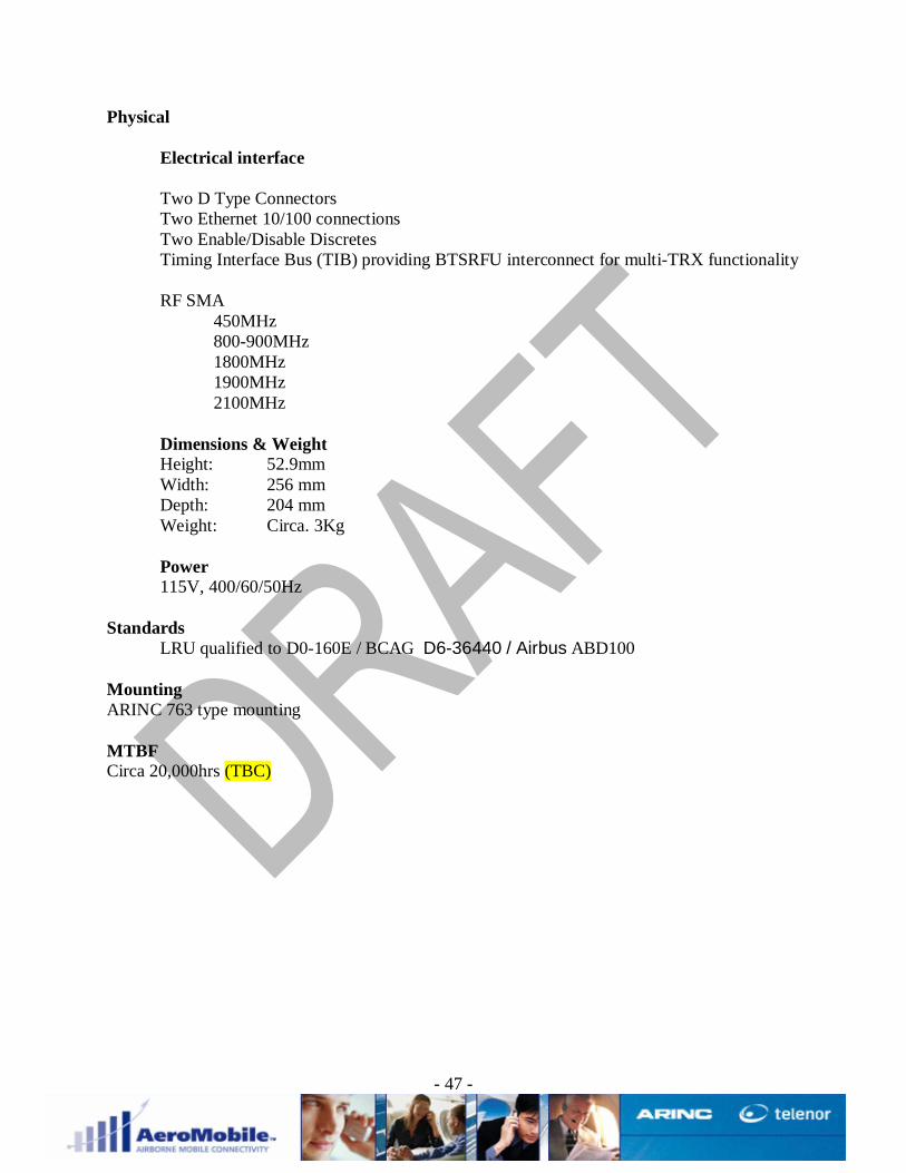
Physical
Electrical interface
Two D Type ConnectorsTwo Ethernet 10/100 connectionsTwo Enable/Disable DiscretesTiming Interface Bus (TIB) providing BTSRFU interconnect for multi-TRX functionality
RF SMA 450MHz 800-900MHz 1800MHz 1900MHz 2100MHz
Dimensions & WeightHeight: 52.9mmWidth: 256 mmDepth: 204 mmWeight: Circa. 3Kg
Power115V, 400/60/50Hz
StandardsLRU qualified to D0-160E / BCAG D6-36440 / Airbus ABD100
MountingARINC 763 type mounting
MTBFCirca 20,000hrs (TBC)

- 48 -

- 49 -
8 Appendix C - Aerial Combiner Unit (AA6129663000-1) Outline Spec
The Aerial combiner Unit is a non-active LRU that combines the RF outputs of the BTSRFU andCRFMU’s. These inputs are combined within the LRU by a network of multiplexers anddiplexers and then transmitted over the aircraft cabin antenna solution, the leaky feeder. Theblock diagram shown to the right provides an overview of the architecture that makes thispossible.
Radio Interface
Figure 16 shows the functional block diagram of the ACU.
Physical
Electrical interfaceSMA RF connectors1900MHz TX BTSRFU 11900MHz RX BTSRFU 11900MHz TX BTSRFU 21900MHz RX BTSRFU 21800MHz TX BTSRFU 11800MHz RX BTSRFU 11800MHz TX BTSRFU 21800MHz RX BTSRFU 2CRFMU1 Port 450MHzCRFMU2 Stbd 450MHzCRFMU1 Port 800/900 MHzCRFMU2 Stbd 800/900 MHzCRFMU1 Port 1800MHzCRFMU2 Stdb 1800MHzCRFMU1 Port 1900MHzCRFMU2 Stdb 1900MHzCRFMU1 Port 2100MHzCRFMU2 Stdb 2100MHzWiFi 2450MHz TX/RX
N Type ConnectorsPort AntennaStarboard Antenna

- 50 -
Dimensions & weight
Figure 15 shows the mechanical outline of the ACU
Height: 52.9mmWidth: 292mmDepth: 206.5mmWeight: Circa. 6Kg
StandardsLRU qualified to D0-160E / BCAG D6-36440 / Airbus ABD100
MountingARINC 763 type mounting
MTBFCirca. 40,000hrs

- 51 -
400.
0
109.00 109.00
416.
00
6xn
7.00
HO
LES
SU
ITA
BLE
FO
R M
6 FI
XIN
GS
MA
TER
IAL
: ALU
MIN
IUM
ALL
OY
FIN
ISH
: A
LOC
RO
M 1
200
CO
NN
ECTO
RS
: 'N
' TYP
E SO
CK
ET &
SM
A SO
CKE
T
PAR
T N
o : 8
0-26
2801
432.
0
251.0
AA
PRO
TOTY
PE IS
SUE
13/1
2/05
PL
POR
T 7
1800
MH
zP
ort C
RFM
U
PO
RT
1119
00M
Hz
BTS
RX
_1
WE
IGH
T : 7
.0kg
APP
RO
X.
PO
RT
1219
00M
Hz
BTS
RX
_2
WiF
i24
00-2
485U
MTS
BAN
DS
tarb
oard
CR
FMU
800-
900M
Hz
Port
CR
FMU
450M
Hz
Port
CR
FMU
PO
RT
20P
ort_
LF
PO
RT
21S
tarb
oard
_LF
PO
RT
318
00M
Hz
BTS
TX
_1P
OR
T 4
1800
MH
z BT
S TX
_2P
OR
T 5
1800
MH
z BT
S R
X_2
PO
RT
618
00M
Hz
BTS
RX
_1P
OR
T 8
1900
MH
z P
ort C
RFM
U
POR
T 9
1900
MH
z B
TS T
X_1
PO
RT
1019
00M
Hz
BTS
TX_2
PO
RT
218
00M
Hz
Sta
rboa
rd C
RFM
U
PO
RT
1319
00M
Hz
Por
t CR
FMU
PO
RT
1845
0MH
zS
tarb
oard
CR
FMU
PO
RT
1980
0-90
0MH
zSt
arbo
ard
CR
FMU
POR
T 1
UM
TS B
AN
DPo
rt C
RFM
U
450/
900/
1800
/190
0/U
MTS
AN
T.C
OM
BIN
ER
13/1
2/05
80-2
6289
1
GD
13/1
2/20
05
BS
13/1
2/20
05
AA
1:4
OU
TLIN
E D
RAW
ING
PL
232.0
94.6
430.
0
Figure 15 Antenna Combining Unit Outline

- 52 -
Figure 16 Antenna Combining Unit Functionality

- 53 -
- 54 -
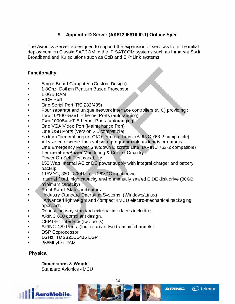
9 Appendix D Server (AA6129661000-1) Outline Spec
The Avionics Server is designed to support the expansion of services from the initialdeployment on Classic SATCOM to the IP SATCOM systems such as Inmarsat SwiftBroadband and Ku solutions such as CbB and SKYLink systems.
Functionality
• Single Board Computer (Custom Design)• 1.8Ghz. Dothan Pentium Based Processor• 1.0GB RAM• EIDE Port• One Serial Port (RS-232/485)• Four separate and unique network interface controllers (NIC) providing :• Two 10/100BaseT Ethernet Ports (autoranging)• Two 1000BaseT Ethernet Ports (autoranging)• One VGA Video Port (Maintenance Port)• One USB Ports (Version 2.0 compatible)• Sixteen “general purpose” I/O Discrete Lines (ARINC 763-2 compatible)• All sixteen discrete lines software programmable as inputs or outputs• One Emergency Power Shutdown Discrete Line (ARINC 763-2 compatible)• Temperature/Power Monitoring & Control Circuitry• Power On Self Test capability• 150 Watt Internal AC or DC power supply with integral charger and battery
backup• 115VAC, 360 - 800Hz. or +28VDC input power• Internal fixed, high capacity environmentally sealed EIDE disk drive (80GB
minimum capacity)• Front Panel Status indicators• Industry Standard Operating Systems (Windows/Linux)• Advanced lightweight and compact 4MCU electro-mechanical packaging
approach• Robust industry standard external interfaces including:• ARINC 600 compliant design.• CEPT-E1 Interface (two ports)• ARINC 429 Ports (four receive, two transmit channels)• DSP Coprocessor• 1GHz, TMS320C6416 DSP• 256Mbytes RAM
Physical
Dimensions & WeightStandard Avionics 4MCU

- 55 -
Power115V, 400/60/50Hz
StandardsLRU qualified to D0-160E / BCAG D6-36440 / Airbus ABD100
MountingStandard 4MCU tray
MTBFCirca 20,000hrs

- 56 -
- 57 -
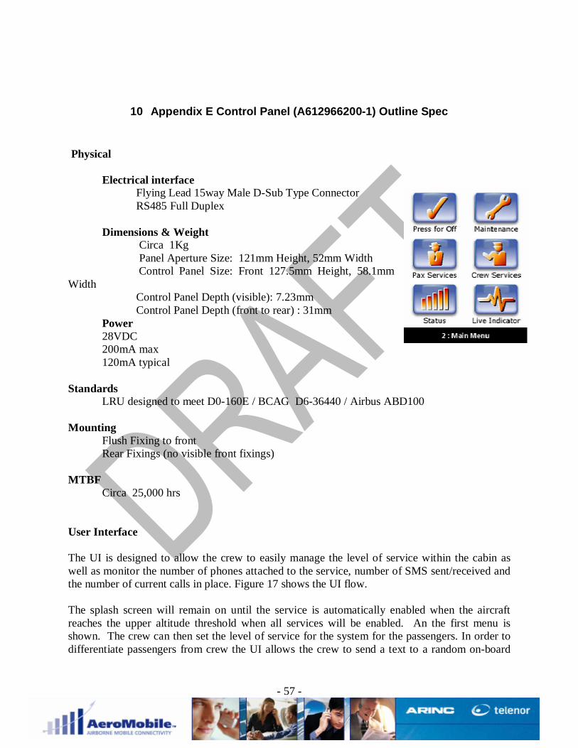
10 Appendix E Control Panel (A612966200-1) Outline Spec
Physical
Electrical interfaceFlying Lead 15way Male D-Sub Type ConnectorRS485 Full Duplex
Dimensions & Weight Circa 1Kg Panel Aperture Size: 121mm Height, 52mm Width Control Panel Size: Front 127.5mm Height, 58.1mmWidth Control Panel Depth (visible): 7.23mm Control Panel Depth (front to rear) : 31mm
Power28VDC
200mA max 120mA typical
StandardsLRU designed to meet D0-160E / BCAG D6-36440 / Airbus ABD100
MountingFlush Fixing to front
Rear Fixings (no visible front fixings)
MTBFCirca 25,000 hrs
User Interface
The UI is designed to allow the crew to easily manage the level of service within the cabin aswell as monitor the number of phones attached to the service, number of SMS sent/received andthe number of current calls in place. Figure 17 shows the UI flow.
The splash screen will remain on until the service is automatically enabled when the aircraftreaches the upper altitude threshold when all services will be enabled. An the first menu isshown. The crew can then set the level of service for the system for the passengers. In order todifferentiate passengers from crew the UI allows the crew to send a text to a random on-board

- 58 -
short code number that will allow all the phones for that flight to be VIP/Crew. This way thesystem can set a different level of service for the VIP/Crew and the passengers.When the aircraft descends below the altitude threshold (or flies over a country with noagreement) the system is automatically disabled and the splash screen is displayed.
INIT DONE/REINITMaintenance
Turn system ON Maintenance /Back BTS#1 alive//faulty CRFMU#1 alive/faultyPassenger services Cabin crew services BTS#2 alive or faulty CRFMU#2 alive/faulty
Status Live indicator Satcom alive or faulty Back
Status/Back Crew or Passenger services is chosen
# calls in progress # phones registered Text MO on/off Text MT on/off# text messages sent # text messages received Voice MO on/off Voice MT on/off
Back Crew phone registration Back
Registration/Back
Back
Register or De-register/Back
Back
SPLASHSCREEN
Please send message to #RANDOM_NUMBER
Register crew phoneDe-register crew phone
Figure 17 Example UI Flow

- 59 -

- 60 -
Appendix F - An Executive Overview of GSM
An executive overview of GSM (Global System Mobile Communications)
In 1985, in a bid to overcome the historic problems associated with the analogue mobile phonenetworks the European regulatory authority, International Telecommunications Union (ITU), setup a committee called ‘Groupe Special Mobile’ to ensure that the radio frequencies allocated tomobile phones were used correctly. The ‘Groupe Special Mobile’ also coordinated plans for anew international operating standard which would allow customers to use the same mobilephone when travelling or ‘roaming’ from one country to the next. The standard became knownas the Global System for Mobile Communications or GSM.
Memorandum of Understanding (MOU)
In 1987, twelve countries agreed to sign a Memorandum of Understanding (MOU) to design andimplement the GSM standard. Commercial development, with the target of covering all majorEuropean cities by 1995, then began in earnest.
In December 1991, a number of leading Telco’s launched a digital GSM service.
In addition to allowing users to take advantage of GSM and roam across different countries,digital systems also had the capacity to cope with substantially more users than its analoguenetwork. It offered customers the clearer telephone calls they were asking for, with lessinterference, as well as protection against illegal eavesdropping and fraud.
Digital technology also opened the door to a whole new era of communications, not just in termsof voice, but also the communication of data, such as faxes, e-mails, and text messages.
At this time there were few approved digital mobile phones available. Those that were on themarket did not support the full range of network and handset features available today. Theseearly mobile phones were also very expensive when compared with current handset prices.
GSM standards
The GSM standard for digital mobile phones is used widely around the world. It comes in four‘flavours’ which are essentially the same, except each uses a different radio frequency. Theseare:
GSM900
The version of GSM working at 900MHz is by far the most widespread, being used by manydifferent networks in dozens of countries around the world, including Vodafone and Cellnet inthe UK. The greater development of GSM900 means that coverage within countries using it isgenerally better, and roaming agreements are more likely to exist.
GSM1800
- 61 -
The 1800MHz version of GSM is also known as PCN. This frequency 1800MHz is sometimeswritten as 1.8GHz. PCN is the only frequency range used by Orange and One 2 One in the UK.
GSM1900
The 1900MHz version of GSM is usually known as Personal Communication Services or PCS.Its frequency of 1900MHz is sometimes written as 1.9GHz. This is the frequency allocated bythe US government for digital mobile phone systems. PCS licences are in place across much ofthe United States, but, as they only started to roll out in 1997, they are still relativelyundeveloped.
GSM850
Originally, the US used only 1900 MHz for its GSM cell phone service. In the last year or so,there has been a growing amount of GSM service on the 850 MHz band. This type of servicewill usually be seen in rural areas, because the 850 MHz band has better range than the 1900MHz band. It can sometimes also found in city areas, particularly if the cell phone company hasspare frequencies unused in the 850 MHz band, but no remaining frequencies to use in the1900 MHz band.
Security on the Digital Networks
Because radio waves can be received by anyone with the right equipment, early wirelesstransmissions were potentially more vulnerable to eavesdropping than fixed-line telephony.Similarly, verifying the owner of a mobile phone is more difficult than checking the status of afixed-line, so mobiles are potentially more vulnerable to impersonation or cloning.
This cloning became a significant problem for early mobile phone networks who were subject towidespread fraud.
These lessons were learned early in the design process for the new GSM networks and thedigital technology added an extra layer of security, by encrypting all voice and data before it wastransmitted. This encryption turns the signal into illegible binary code of 1’s and 0’s, so that it ismeaningless to anyone listening in.
Radio Waves
To understand how a mobile phone network operates, it helps if we explain certaincharacteristics of a radio wave.
Anyone who owns a mobile phone wants to use it wherever they choose. Despite the billions ofpounds spent providing mobile phone coverage there are still some places where the radiowaves from the networks cannot reach. To understand why this happens, it helps to knowsomething about radio waves.
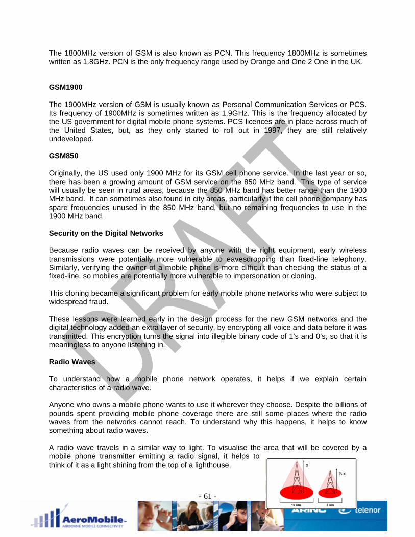
A radio wave travels in a similar way to light. To visualise the area that will be covered by amobile phone transmitter emitting a radio signal, it helps tothink of it as a light shining from the top of a lighthouse.

- 62 -
The taller the lighthouse, the greater the distance from which the light can be seen. Similarly,the higher the radio transmitter, the greater the area it can cover.
Height is not everything, however. The brighter the light in a lighthouse, the further away it canbe seen.
Why radio signals do not get through
If the world was perfectly flat without any buildings, the area covered by each transmitter wouldonly depend on its height and power. In reality, of course, things are very different. Hills,buildings, and even trees can block the radio signal. Some ways in which this happens areexplained below.
Shadowing
Radio waves and light both travel in straight lines and areaffected by obstructions which can produce 'shadowing.'Radio shadowing can occur if a building or a hill, for example,lies between the user and the radio transmitter. If the heightof the aerial can be increased, the radio signal shadow will bereduced or eliminated. Normally, however, such problemscan only be removed at the considerable expense ofconstructing a new base station on the other side of theobstruction.
Reflection
Radio signals can reflect off metallic surfaces, just like lightreflecting off shiny surfaces. High signal loss can occur insidebuildings if metal claddings are used in their construction. Somebuildings use tinted glass windows with a metal coating intended toreflect excess light. These surfaces can also reflect radio waves.Such radio ‘reflection’ can cause weak signals with affected
buildings.
Attenuation
Radio signals can be absorbed by the fabric of the buildings or bytrees. This is known as ‘attenuation.’ In a wood for example, it issometimes possible to get a better signal in the winter, when the treesare bare, than in the summer.
Key components of a GSM network

- 63 -
When we use a mobile phone we generally take for granted that we will have a connectionevery time. There are however, many different elements that go to make up the networkinfrastructure.’
BTS (Base Transceiver Station)
The transmitter, or to use its full name the BaseTransceiver Station (BTS), is responsible fortransmitting radio signals to any mobile phone withinits range and receiving signals back from the handset.The base station consists of control equipmenthoused in a purpose-built cabin together withantennas. A typical early radio base station consistedof between nine and 15 antennas, each more thanthree metres in length, usually mounted on a building or mast at a height of 24-30 metres abovethe ground. Current base stations are made using lightweight, slimline lattice masts and polesand a new range of smaller and more efficient antennas. These installations can be painted tominimise their visual impact and enhance their integration into the urban and rural landscape.
Cell Sites
The area covered by each base station is generally referred to as a‘cell’ which is why mobile phones are sometimes called cell orcellular phones. Each cell has a number of radio channelsallocated to it. These radio channels can be used to deliverwhatever type of communication is being used, including data,voice, and fax.
Hand over/hand off
Hand over
Thousands of different cells, each with their ownbase station, make up the network. As mobilephone users travel around the country, they movethrough different cells and their signal is passedfrom one cell to the next by a process known as‘hand over’ or ‘hand off.’Networks are designed to provide continuouscoverage as the mobile user travels from one areato another. To ensure that a mobile user can dothis without losing or ‘dropping’ the radio signalrequired to hold a conversation, each cell must overlap the cell next to it.
The network of overlapping cells is normally illustrated as a honeycomb pattern. In fact, thepresence of hills, buildings, and areas of high population mean the true pattern is less precise.
When siting base stations, the network operator must assess many different factors that willinfluence the amount of ‘traffic’ that will be generated including population density, land use, and

- 64 -
even income. Mobile phone traffic is usually high in citycentres, lower in small towns, and lowest of all in areas ofcountryside. Once the network operator has estimated thelikely traffic load, they can plan how base stations are sitedto provide adequate cover.
There are a limited number of radio channels available ineach cell. Therefore, lots of small cells give far highercapacity than a few large cells. The radius of a cell can beas large as 15km in flat, sparsely populated areas and as small as 0.5km in densely populatedareas.
Expanding the network
The base stations for the early analogue networks were relatively far apart. But digital mobilephones cannot send a signal as far as analogue handsets. Consequently, radio base stations
for a digital network must be closer together. This is why more digital basestations are required to achieve the same level of coverage as is provided bythe original analogue network.
How Mobile Phones Work
The final element we will consider is the mobile phone itself. It is a highly sophisticated radiocommunication device that connects a user to the cellular network via the air interface.
A digital mobile phone can only be used to make or receive calls when fitted with an activeSubscriber Identity Module (SIM) card, although some overseas GSM networks permitemergency calls without one.
The SIM card is a small plastic card containing a tiny silicon ‘chip’ or ‘microprocessor.' Oftenreferred to as a ‘smartcard,’ the SIM records information about the customer’s identity or‘subscription’ and security-related data that helps to protect the phone from illicit eavesdroppingor cloning. The SIM Card can also store a range of information that can be controlled by thecustomer via their mobile phone including commonly dialled or abbreviated telephone numbers
A mobile phone communicates with a cell network using a complex set of protocols. Morefundamentally these protocols dictate the following:
1) A mobile phone will not transmit until it receives a valid signal from a network.2) The output power of a mobile phone can vary between 0dBm (circa. 1 mW) and 33dBm
(circa. 2 W). The power level of the phone is controlled by the base station and is largelydependant on the distance the phone is from the network.
3) The network will give the phone details of any cells that currently surround the cell site thephone is logged onto. Recognising that many mobile phone users are moving, the phonecontinuously checks the signal strengths of these surrounding cells and will “hand callsover” to neighbouring cells as appropriate.
4) In addition to the above process a mobile phone continuously scans for it home network.The “home network” is the network with which the mobile phone is subscribed to.
3rd Generation (UMTS)
- 65 -
The year 2000 saw the explosion of interest in Wireless Application Protocol (WAP) enabledmobile telephones, that use micro-browser technology to view specially written Internet pages.During 2001 the take up of this WAP technology has been further enhanced by the introductionof General Packet Radio Service (GPRS), which provides faster data transfer rates and aninnovative charging system. This provides a fast and cost effective way for mobile phonecustomers to access and interact with Internet-based services from their mobile phone.
Looking slightly further forward the introduction of 3rd generation (UMTS) mobile phonenetworks promises even faster data transfer speeds and the introduction of innovative servicessuch as video postcards instead of text messages.
Fundamentally all 3G phones revert back to GSM standards in areas where 3G is not available.
Connection types explained
There are three main ways of buying and running a mobile handset. These are:
Pay in advancePrepayAccount or contractAccount/contract
Customers buy a mobile handset at a heavily subsidised price, in return for which they sign upto a contract that ties them to the network for a fixed period of time (usually 1 year). During theperiod of the contract, the customer pays a fixed fee each month. This fee is commonly called'line rental' and gives the customer access to the Vodafone network to make and receive callsand use a wide range of services.
The reason that networks and service providers are able to offer the handset at such a low priceand offer connection bonuses and other incentives is that the customer is certain to spend afixed amount during the period of the contract (i.e., the line rental x 12 months).
The amount of subsidy and bonuses that can be given for a connection may vary depending onthe price plan that the customer is connected to. Customers who are higher users and connectto the higher value price plans will obviously generate more income during the course of a 12-month contract and will therefore be of more value to the service provider and network.
Pay in advance
'Pay in advance' is a way of buying and owning a contract mobile phone that appeals to someusers, and it potentially gives them more control over their monthly spending.
The customer buys a mobile phone at a subsidised price and in effect pays up front for the 12-month line rental (this is also often at a discounted price). Potentially, this gives the customerthe benefits of the pre pay service as well as the benefits of the contract offering.
However, these 'pay in advance' packages are becoming less popular with the networks andservice providers for a variety of reasons. In particular, these packages are often on a limitedrange of price plans and customers do not necessarily buy the price plan that is mostadvantageous for them. These packages make it hard for networks to promote customer loyalty,

- 66 -
as at the end of the 12-month period the customer is likely to go back out onto High Streetlooking for another similar deal.
Prepay
Introduced to the mobile phone market in 1996. Since that time, it has become one of the mostpopular ways of owning and running a mobile phone.
With prepay, customers tend to pay more for their mobile handset, but are not tied to any fixedperiod and can simply stop using the phone if they want to, without penalty. This flexibilitymeans that networks have no guaranteed return when a prepay mobile phone is sold; therefore,the subsidy, if any, on the price of the handset and on the connection is less than that given witha contract.
Prepay mobile phone packages do have a number of advantages over the contract method;however, many customers buy prepay packages without fully investigating the available optionsand often end up with a prepay package when a contract would be more appropriate.
During this module, we will discuss some of the pros and cons of prepay and contract packagesto give you the tools to ensure that your customers end up with the right package for them.
GPRS
General Packet Radio Service gives the existing network the ability to handle packets of data.This has the potential to increase the speed by four times.
With a GPRS handset you are actually always connected, whereas with non-GPRS phones youhave to log in every time you want to access information.
It's like the difference between using a dial-up modem and having a fixed open connection tothe Internet. The connection is always "on", but customers are only charged for the data theyreceive - not for the time they are connected, as is currently the case.
Value added services (VAS)
Network services and features are, as the name suggests, developed and offered by thenetwork operator, not the handset manufacturer. As such, their availability may vary dependingon which network the customer is using.
In line with the GSM standard introduced in 1987, some network services and features arecommon to all GSM network operators. These services and features are usually accessed bytyping commands into the handset. These commands are then recognised by the network andthe requested action is performed.
A good example is 'Call Forward Unconditional', which can be activated from any mobile phone,on any GSM network anywhere in the world by keying in the handset command **21* [numbercall to be forwarded to] # Send.
These types of commands are referred to as Structured Handset Commands.

- 67 -
Other network services and features can only be activated or interrogated by keying in handsetcommands that are specific to an individual digital network, and can only be accessed by amobile phone connected on to that network.These commands are known as UnstructuredHandset Commands.
In addition to the network's own commands, most current mobile phones now also offer accessto network facilities within their own menu structure. Using the phone's own menu can often beeasier than having to memorise and type in the various network codes in order to requestservices. Customers can simply go to the menu option on their mobile phone and select theappropriate service or feature from there. Instructions on how to access services and featuresfrom a handset are usually provided in the user manual supplied with the phone. So now, let'stake a closer look at the different services and features our customers can access from theirmobile phone.
Voicemail
Voicemail functions rather like an answer phone at home. It works by setting up a personalelectronic mailbox that resides safely inside the network.
All customers connecting to a network are allocated their own personal Voicemail mailboxnumber, which is linked to their individual mobile phone number.
If customers do not wish to, or are unable to, answer a call to their mobile, the incoming call canbe forwarded automatically to their mailbox and answered by an automated greeting. Theincoming caller can then record their own greeting.
Call Diverting
Call Diverting is a particularly useful service for customers whouse their mobile phone for work. These customers can forward ordivert calls to another colleague or assistant, while they are in ameeting or out of action for whatever reason.
If customers are busy receiving or making another call, or havetheir phones switched off, they can forward incoming calls to anyother number in the UK including, of course, their Voicemail mailbox, provided that it has beenset up.
Text Messaging
A text message can be received at the same time as a voice or data call is being made. Forexample, if a mobile phone is engaged for a long period of time because the user has becomeinvolved in a lengthy conversation, a text message can be sent, perhaps requesting that theycall home, the office, or a customer when the voice call is finished.
Text messaging is also an extremely useful way of contacting someone who is not respondingto incoming voice calls - perhaps if the user is abroad. Text messages can be sent to a phonethat is roaming anywhere in the world, as long as the customer is roaming on a network in acountry that supports text messaging.

- 68 -
Text messages are usually received extremely quickly - normally within ten seconds.
Another benefit of text messages is that they are visual. This means they can be used in noisyenvironments when it may be difficult to talk or to be heard, such as on a train, at a busyexhibition, or even in a noisy pub.
Text messages are an ideal way to keep in contact when a voice call is inappropriate orinconvenient - in a restaurant, for example, or a meeting, or late at night. A text message will stillget through to the mobile, even if incoming voice calls have been diverted to another number(such as the person's Voicemail service). And, of course, they cannot be overheard in the sameway that a voice call can.
WAP and data
The Wireless Application Protocol
The WAP protocol is the leading standard for information services on wireless terminals likedigital mobile phones. The WAP standard is based on Internet standards (HTML, XML andTCP/IP). It consists of a WML language specification, a WMLScript specification, and a WirelessTelephony Application Interface (WTAI) specification. WAP is published by the WAP Forum,founded in 1997 by Ericsson, Motorola, Nokia, and Unwired Planet. Forum members nowrepresent over 90% of the global handset market, as well as leading infrastructure providers,software developers and other organizations.
WAP Micro Browsers
To fit into a small wireless terminal, WAP uses a Micro Browser.A Micro Browser is a smallpiece of software that makes minimal demands on hardware, memory and CPU. It can displayinformation written in a restricted mark-up language called WML.The Micro Browser can alsointerpret a reduced version of JavaScript called WMLScript.
Examples of WAP useChecking train table informationTicket purchaseFlight check inViewing traffic informationChecking weather conditionsLooking up stock valuesLooking up phone numbersLooking up addressesLooking up sport resultsUnderstanding roaming
These days most mobile phone customers have at least some awareness that mobile phonescan be used abroad. Of course, people in the mobile phone industry have an even greater levelof awareness and understanding. However, though most people have some knowledge of GSMroaming, many people are completely unaware of the extent to which mobile communicationshave become a truly worldwide phenomenon.

- 69 -
Receiving calls whilst roaming
When a customer is roaming abroad, callers simply dial their phonenumber as usual. All of the customer's incoming calls will beautomatically routed to the foreign network that they are using at thetime. Provided that the customer has their phone turned on, theywill receive the call just as if they were in the UK.
Making calls whilst roaming
When a customer arrives in another country with a compatible GSM network and wishes to usetheir mobile phone, they simply turn it on in the normal way. The phone will take a few secondsto register as the foreign network identifies the phone. It checks that the customer has asubscription, and checks whether the customer's mobile phone is barred from either roaming ormaking international calls.
When a customer makes a call whilst roaming they must remember a few simple rules. If acustomer is abroad, unless they are dialling a local number in the country they are roaming theyare always making an international call. This also applies if the customer makes a call back tothe UK. This means that the customer must remember to use the international dialling codewhen calling back to the UK.
When making an international call, the customer should dial using the following format:Dial a +. This tells the network that the customer wishes to be routed internationally.Dial the country code (for the UK the code is 44).Dial the number in full, but drop the first 0 in the number.
When roaming abroad the customer will pay the foreign networks published rates for makingcalls. Some foreign networks also levy an additional visitors roaming charge on top of theirpublished tariff.
Whatever the cost of the call, the telco converts the amount to pounds sterling and adds ahandling charge.
Call charges are subject to exchange rate fluctuations, price changes by foreign networks andvat. For this reason, it is impossible to give exact details of every call charge in every countrywhere Vodafone has a roaming agreement. However, Vodafone's Guide to using your Vodafoneabroad does give an idea of some of the call charges you can expect to pay to certain areasand is available here.
Another area that can often cause confusion is the fact that unlike using a mobile phone on theirhome network, when customers roam abroad they incur charges for both making outgoing callsand receiving incoming calls.
Why networks charge for incoming calls

- 70 -
When someone calls a mobile phone user, that user could in fact be located anywhere in theUK or indeed the world. There would be no reason for the caller to know where the customer is,unless they had been told in advance.
It is important to know how calls are routed to and from a mobile phone whilst roaming abroad inorder to explain to customers how charges are incurred.
There is obviously a real cost in forwarding an incoming call internationally and as the caller hasno idea where the customer is, it would be unfair to expect them to pay a higher charge forcalling a roaming customer. For this reason when a caller makes a call to a customer who isroaming, they conduct their call in the normal way and will only be charged the usual rate fordialling a mobile phone. The call charge will NOT vary depending on the location of the mobilethey are calling.
The Vodafone customer who is abroad incurs a charge for receiving the international leg of theincoming call; (this is the part of the call that is routed from the UK out to the network on whichthe customer is roaming). They will pay this charge for the duration of the call.
What happens when you call another roaming customer?
If a customer travelling in France calls a Vodafone customer in Germany for instance, the callwill first be routed from the French network to the Vodafone network in the UK, as the mobilenumber being called is registered in the UK. The UK network, realising that the number beingcalled is currently registered with a German network, then forwards the call to Germany.
The German network then passes the incoming call to the mobile customer roaming inGermany. The mobile user calling from France will be charged theFrench networks international tariff for calling back to the UK. Themobile customer receiving the call in Germany is charged for theincoming international leg of the call from the UK out to Germany.
When customers return home from abroad they should turn theirmobile phone on as soon as they are safely able to do so. This willre-register their mobile phone back in the UK. If a customer doesnot re-register their phone, incoming calls may continue to beforwarded to the foreign network on which they last registered andmay incur incoming call charges as a result.
Coverage whilst roaming
As we mentioned earlier, coverage and services will vary from one network to another. Someforeign networks do not provide the same standard of coverage or capacity as we are used to inour home country.

- 71 -