rad-star 2 user's guide - intrepid control systems, inc. · 2017-09-15 · your rad-star 2...
TRANSCRIPT

Intrepid Control Systems, Inc.31601 Research Park Drive Madison Heights, MI 48071 USA(ph) +1-586-731-7950 (fax) +1-586-731-2274www.intrepidcs.com www.aeta-rice.com
RAD-Star 2Active Tap, Media Converter and
Network Interface for Automotive Ethernet and CAN FD
User’s GuideVersion 1.0 - September 1, 2017

RAD-Star 2 User’s Guide
i © 2017 Intrepid Control Systems, Inc.Version 1.0 - September 1, 2017
Version History
Version Number Date Description / Major Changes
1.0 2017/09/01 Initial release.

RAD-Star 2 User’s Guide
ii © 2017 Intrepid Control Systems, Inc.Version 1.0 - September 1, 2017
Table of Contents1 Introduction and Overview ..........................................................................................................................11.1 Introduction ................................................................................................................................................11.2 Package Contents ......................................................................................................................................11.3 Operational Overview ................................................................................................................................21.4 Block Diagram ............................................................................................................................................71.5 Summary of Key Features .........................................................................................................................71.6 Hardware and Software Requirements ......................................................................................................9
2 A Tour of RAD-Star 2 Hardware ...............................................................................................................102.1 Case and Overall Design .........................................................................................................................102.2 Membrane LED Display and Keypad .......................................................................................................122.3 Vehicle Network Interface Side Connectors .............................................................................................142.4 PC Interface Side Connectors .................................................................................................................152.5 Included Cables and Cable Assembly .....................................................................................................16
3 Hardware and Software Setup .................................................................................................................183.1 Vehicle Spy and Driver Installation and Setup .........................................................................................183.2 Driver and API Support File Installation and Setup ..................................................................................253.3 Hardware Hookup Diagrams ....................................................................................................................313.4 Vehicle Network and Power Connections ................................................................................................323.5 PC Connection .........................................................................................................................................32
4 DeviceConfiguration .................................................................................................................................344.1 Starting and Using neoVI Explorer ...........................................................................................................344.2 System Settings and Firmware Updates ..................................................................................................374.3 General Settings and Product Details ......................................................................................................404.4 Standard CAN Networks (HS CAN and MS CAN) ...................................................................................404.5 LIN Network (LIN) ....................................................................................................................................434.6 One Pair Ethernet (BroadR) Automotive Ethernet Networks ...................................................................434.7 Time Sync ICS Hardware.........................................................................................................................454.8 Network Enables ......................................................................................................................................45
5 Reference: Connector Pinouts .................................................................................................................475.1 BroadR-Reach Nano MQS Connector Pinout ..........................................................................................475.2 DB-9 Conventional Network Interface Connector Pinout .........................................................................47
6 Support Contact Information .....................................................................................................................496.1 ICS United States Headquarters ..............................................................................................................496.2 ICSInternationalOffices ..........................................................................................................................49

RAD-Star 2 User’s Guide
1 © 2017 Intrepid Control Systems, Inc.Version 1.0 - September 1, 2017
1 Introduction and Overview
1.1 Introduction
Thank you for purchasing an Intrepid Control Systems RAD-Star 2 active tap and media converterforAutomotiveEthernet(AE).TheRAD-Star2allowsyoutomonitoralltrafficona BroadR-Reach (100BASE-T1 compatible) link between two AE devices. Once inserted in thelink,theRAD-Star2passesalltrafficbetweenthedeviceswithvirtuallynoaddedlatency,while sending a timestamped copy of each message to a standard Ethernet device (such as a laptop PC) for monitoring. The RAD-Star 2 can also be used as a media converter, allowing up to two ECUs to be interfaced directly to a PC or other conventional Ethernet device. In both applications, it is also possible to transmit messages from the PC to the ECU(s) using a tool like Intrepid’s Vehicle Spy software, allowing those devices to be directly controlled.
As its name suggests, the RAD-Star 2 is Intrepid’s second generation single active tap tool and includes numerous improvements over the original RAD-Star. These include improved performance, a Gigabit Ethernet port, the ability to interface two devices in media converter mode instead of one, raw media converter mode, a membrane LED display and keypad, the ability to interface over USB, ruggedized packaging, and much more. The RAD-Star 2 also adds support for two CAN FD channels in addition to its Automotive Ethernet capabilities, allowing you to work with conventional CAN devices and to gateway between CAN and AE.
Note: BroadR-Reach (sometimes abbreviated as BroadR or just BR) is sometimes also called One Pair Ethernet (OPEN or
OP). In 2015, BroadR-Reach was published as a formal Ethernet standard in IEEE 802.3bw and given the designation 100BASE-T1. While not 100% identical, the two are nearly the same; the RAD-Star uses BroadR-Reach transceivers, but is compatible with 100BASE-T1.
1.2 Package Contents
Your RAD-Star 2 package includes both hardware and software.
Hardware
UponopeningtheRAD-Star2box,youshouldfindaRAD-Star2QuickStartGuideontopwiththedeviceitselfsecuredundertransparentplasticfilminacardboardholder.Removetheguide, the device and the cardboard, and you’ll see the following additional items:
RAD-Star 2 User’s Guide
2 © 2017 Intrepid Control Systems, Inc.Version 1.0 - September 1, 2017
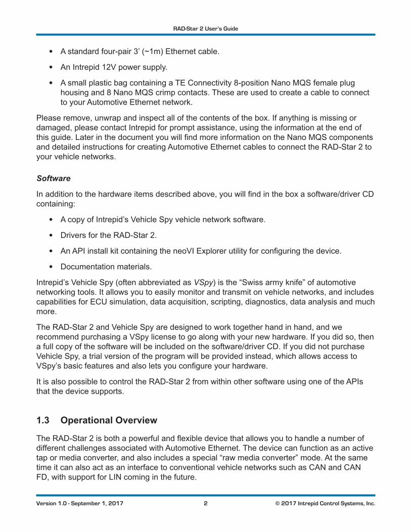
• A standard four-pair 3’ (~1m) Ethernet cable.
• An Intrepid 12V power supply.
• A small plastic bag containing a TE Connectivity 8-position Nano MQS female plug housing and 8 Nano MQS crimp contacts. These are used to create a cable to connect to your Automotive Ethernet network.
Please remove, unwrap and inspect all of the contents of the box. If anything is missing or damaged, please contact Intrepid for prompt assistance, using the information at the end of thisguide.LaterinthedocumentyouwillfindmoreinformationontheNanoMQScomponentsand detailed instructions for creating Automotive Ethernet cables to connect the RAD-Star 2 to your vehicle networks.
Software
Inadditiontothehardwareitemsdescribedabove,youwillfindintheboxasoftware/driverCDcontaining:
• A copy of Intrepid’s Vehicle Spy vehicle network software.
• Drivers for the RAD-Star 2.
• AnAPIinstallkitcontainingtheneoVIExplorerutilityforconfiguringthedevice.
• Documentation materials.
Intrepid’s Vehicle Spy (often abbreviated as VSpy) is the “Swiss army knife” of automotive networking tools. It allows you to easily monitor and transmit on vehicle networks, and includes capabilities for ECU simulation, data acquisition, scripting, diagnostics, data analysis and much more.
The RAD-Star 2 and Vehicle Spy are designed to work together hand in hand, and we recommend purchasing a VSpy license to go along with your new hardware. If you did so, then afullcopyofthesoftwarewillbeincludedonthesoftware/driverCD.IfyoudidnotpurchaseVehicle Spy, a trial version of the program will be provided instead, which allows access to VSpy’sbasicfeaturesandalsoletsyouconfigureyourhardware.
It is also possible to control the RAD-Star 2 from within other software using one of the APIs that the device supports.
1.3 Operational Overview
TheRAD-Star2isbothapowerfulandflexibledevicethatallowsyoutohandleanumberofdifferent challenges associated with Automotive Ethernet. The device can function as an active tap or media converter, and also includes a special “raw media converter” mode. At the same time it can also act as an interface to conventional vehicle networks such as CAN and CAN FD, with support for LIN coming in the future.

RAD-Star 2 User’s Guide
3 © 2017 Intrepid Control Systems, Inc.Version 1.0 - September 1, 2017
Active Tap Mode
Due to the high performance and complexity of BroadR-Reach (and 100BASE-T1), typical approaches for interfacing to a network—such as attaching a probe to the bus—do not work. This problem is resolved by interposing the RAD-Star 2 between two Automotive Ethernet devices, typically an ECU and a switch, but possibly also two ECUs. Instead of connecting the two devices directly, both are attached to the BroadR-Reach ports of the RAD-Star 2. The Gigabit Ethernet link of the RAD-Star 2 is then connected to a laptop PC or similar conventional Ethernet device (USB can also be used).
Note: The term “tap” has a dual meaning: it refers to the act of tapping into a network (such as used in the phrase “wire tap”).
It also is sometimes considered an acronym for “test access point,” since a tap does indeed act as an access point for testing, though you can do much more than that with the RAD-Star 2. For simplicity, in this document we will just use the word “tap”.
Onceconfigurationiscomplete,theRAD-Star2issetupasa“middleman”inthenetwork,managed by a custom-designed processor within the unit. When either AE device transmits, the RAD-Star 2 receives the message and retransmits it to the other device with only a minor delay for processing. The RAD-Star 2 also sends a copy of the message over its Gigabit Ethernet or USB connection to the PC, so it can be viewed and analyzed within software like Vehicle Spy. These frames are encapsulated in a custom wrapper (the details of which can be found later in this section).
The interface provided by the RAD-Star 2 is full-duplex and bidirectional. This means that in addition to using the PC to monitor messages sent by the Automotive Ethernet nodes attached to it, you can create and send custom messages from the PC to the nodes as well. This allows youtoquery,test,configureandmanagethesenodesusingVehicleSpy.
Figure 1 depicts how the RAD-Star 2 functions when inserted into a typical Automotive Ethernet network as a tap. Note that operation is the same whether tapping a link between an ECU and a switch or between two ECUs.

RAD-Star 2 User’s Guide
4 © 2017 Intrepid Control Systems, Inc.Version 1.0 - September 1, 2017
AENode 2
AENode 1
Node 2 to Node 1
Node 1 to Node 2
AENode 2
AENode 1
RAD-Star 2Conventional
EthernetNetwork
PC to Node 1
Node 1 to Node 2
Node 2 to Node 1
Node 1 to PC
Node 2 to PC
PC to Node 2
Figure 1: Using the RAD-Star 2 as an Active Tap. On the left, a standard connection between two Automotive Ethernet nodes, which could be a switch port and an ECU or two ECUs. On the right, the network that results after inserting the RAD-Star2asanactivetap.MessagesflowfromNode1throughtheRAD-StartoNode2,andvice-versa,maintainingnormal operation of the network (solid blue arrows). In addition, copies of each message are transmitted by the RAD-Star 2 to the attached conventional Ethernet network (dashed blue arrows). Optionally, messages from a PC or other device on the Ethernet network may also be sent to both nodes (red arrows).
Media Converter Mode
Instead of being interposed in a link between two Automotive Ethernet nodes, the RAD-Star2canbeconfiguredtointerfacetotwonodesindependently.Anytrafficreceivedbyanode will be converted from Automotive Ethernet to standard Ethernet (or USB) and sent to thePC.Conversely,trafficfromthePCwillbeconvertedtoBroadR-Reachandsenttotheappropriate node. Since in this operating mode the RAD-Star 2 is converting between two media—Automotive Ethernet and either Gigabit Ethernet or USB—it is said to be acting as a media converter. Again here, frames are encapsulated in a proprietary wrapper, which will be explained shortly.
Figure 2 depicts the logical operation of the RAD-Star 2 when used in this manner. Note the differencebetweentapandmediaconvertermode:trafficisnotcopiedbetweentheAEnodes,so they behave independently.

RAD-Star 2 User’s Guide
5 © 2017 Intrepid Control Systems, Inc.Version 1.0 - September 1, 2017
AENode 2
AENode 1
AENode 2
AENode 1
RAD-Star 2Conventional
EthernetNetwork
PC to Node 1
Node 1 to PC
Node 2 to PC
PC to Node 2
Figure 2: Using the RAD-Star 2 as a Media Converter. On the left, two independent (unconnected) Automotive Ethernet nodes. On the right, the two nodes connected to the RAD-Star 2 and a PC in media converter mode. Each node can send to the PC, and vice-versa, simultaneously and independently.
Raw Media Converter Mode
In addition to its “normal” media converter mode, the RAD-Star 2 supports a special “raw” media converter mode that is intended for special applications. In this mode, one of its BroadR-Reachportsisconfiguredtoactasa“pure”mediaconverteratthephysicallayerlevel,whilethe other is disabled. Communication is always through Gigabit Ethernet (not USB) and no wrapper is used on frames.
In this mode the RAD-Star 2 effectively operates the same way as Intrepid’s RAD-Moon media converter device. One difference, however, is that frame buffering is supported in the RAD-Star 2 in this mode, allowing a BroadR-Reach device to be connected to a conventional Ethernet networkrunningat10Mb/s,ifneeded.
This mode of operation is illustrated in Figure 3.

RAD-Star 2 User’s Guide
6 © 2017 Intrepid Control Systems, Inc.Version 1.0 - September 1, 2017
AENode 1
RAD-Star 2Conventional
EthernetNetwork
PC to Node 1
Node 1 to PC
Figure 3: Using the RAD-Star 2 as a Raw Media Converter.InthisconfigurationthefirstBroadR-Reachchannelisconfiguredtoactasapurephysicallayermediaconverter,attachingthePCtoasingleAEnode;theotherchannelisdisabled.Trafficispassedbetweendeviceswithouttheuseofaframewrapper.
Timestamping and Frame Wrapping
The RAD-Star 2 records the time that each message is received on any of its Automotive Ethernet ports. This hardware-level timestamp is then transmitted in a special wrapper frame over its Gigabit Ethernet or USB link, encapsulating the original message. The wrapper frame contains its own Ethernet header and Frame Check Sequence (FCS)field,alongwithanextraheadercontaininginformationspecifictotheRAD-Star2.Asmentionedabove,thiswrapperis used in the two “normal” modes (active tap and media converter) but not in raw media converter mode.
Ethernet controllers normally discard any frames received for which an error has been detected,andstriptheFCSerror-detectionfieldevenonvalidframes.TheRAD-Star2’sspecial wrapping mechanism allows it to capture BroadR-Reach frames in their entirety, includingtheFCSfield,ensuringthaterrorframesarepreservedsotheycanbeanalyzed.
Conventional Vehicle Network Interfacing
In addition to its Automotive Ethernet capabilities, the RAD-Star 2 can act as an interface to conventional vehicle networks. It includes hardware for 2 CAN channels with CAN FD support. Both channels are captured simultaneously, and are hardware time-stamped with great accuracy. Non-Ethernet messages are encapsulated into Ethernet frames and transmitted to the PC over the same connection used for BroadR-Reach data, where they are decoded and displayed by Vehicle Spy. The RAD-Star 2 also has hardware support for one LIN channel, whichwillbeenabledinafuturefirmwareupdate.

RAD-Star 2 User’s Guide
7 © 2017 Intrepid Control Systems, Inc.Version 1.0 - September 1, 2017
1.4 Block Diagram
Figure 4 shows a simple block diagram of the RAD-Star 2. All operations are controlled by the central processor, which is implemented as a custom system-on-a-chip (SoC) integrated circuit.Thisdesignprovidespowerfulflexibilityandalsoallowstheimplementationofnewfeaturesinexistinghardwarethroughfirmwareflashupdates.Thevariousphysicallayerchipsandnetwork-specificcontrollersconnecttotheappropriateconnectorsonthedeviceforattachment to vehicle networks.
RAD-Star 2System on Chip (SoC)
USB 2.0PHY
BroadR-ReachPHY 1
GigabitEthernet
PHY
CAN FDPHY 1
CAN FDPHY 2
LIN PHY(Coming Soon)
BroadR-ReachPHY 2
Figure 4: RAD-Star 2 Block Diagram.
1.5 Summary of Key Features
The RAD-Star 2 is one of the most powerful vehicle networking tools ever developed, providing extensive analysis and simulation options for both conventional and Automotive Ethernet networks. To give you an idea of how much you can do with the RAD-Star 2, here’s a summary of the device’s most important design, construction, operational and performance features.

RAD-Star 2 User’s Guide
8 © 2017 Intrepid Control Systems, Inc.Version 1.0 - September 1, 2017
Construction, Controls and Cabling
• Compact design: 5.4” x 3.4” x 1.5” (14 x 9 x 4 cm).
• Light weight: about 11 oz (315 g).
• Solid anodized aluminum case.
• Thick rubber end boots for shock protection.
• Ruggedized metal connectors.
• Cable interfaces on sides for easier connections.
• Multiple LEDs for status output.
• Included cables and connector contacts for vehicle network interfacing.
• Included 12V power supply.
Power and Performance
• Powerful SoC design.
• Field-upgradeablefirmware.
• Support for 4.5V to 36V input power.
• Low power consumption (0.5A @ 12V).
• 64-bit timestamping with 10 ns accuracy on all networks.
Automotive Ethernet Interfaces and Features
• Two BroadR-Reach (100BASE-T1 compatible) Broadcom Automotive Ethernet PHYs.
• One Gigabit Ethernet PHY with industry standard RJ-45 jack.
• One USB Type B connector.
• OneDB-9connectorforinterfacingtoCAN/CANFD(andfutureLIN)networks.
• Switchable between one active tap, two media converter ports and one raw media converter using surface touchpad.
• Full-duplex support for simultaneous data transmission and reception across all PHYs.
• AVB/TSNsupport.
• Ethernet frame preemption support.

RAD-Star 2 User’s Guide
9 © 2017 Intrepid Control Systems, Inc.Version 1.0 - September 1, 2017
Conventional Network Interfaces and Features
• Two dedicated Dual Wire (DW) CAN channels (ISO 11898-2).
• CAN FD support with software selection of ISO and non-ISO CAN FD versions.
• 1 LIN channel (coming soon).
1.6 Hardware and Software Requirements
You will need only a small amount of support hardware to make use of your RAD-Star 2:
• A vehicle network, either within an actual vehicle or in a test bench environment.
• A standard electrical plug to use the included DC power adapter. You also have the option of providing power via a custom cable on your network bench.
• A PC or other device with an available Gigabit Ethernet or USB 2.0 (or higher) port.
• Cablesand/orconnectorstoconnecttotheBroadR-ReachnodesinyourAutomotiveEthernet network.
• A crimping tool to attach wires to the provided crimp contacts and secure them within the Nano MQS plug housings. See Section 2.5 for more details.
Additional cables may also be needed, depending on the nature of the network to which the RAD-Star 2 is being connected.
Intrepid’s Vehicle Spy Professional is recommended for use with the RAD-Star 2, and provides everything you need to set up your hardware and use all of its capabilities. The setup program for VSpy will also install the necessary drivers for your RAD-Star 2. If you do not have a VSpy license, you can use the included Vehicle Spy trial version for basic network interfacing and driver setup.
It is also possible to use Vehicle Spy with third-party or custom software, via the Intrepid API. The necessary drivers can also be set up using the API kit installer. All of this software comes with the RAD-Star 2, or if necessary, can be downloaded from the Intrepid web site at http://www.intrepidcs.com. Installation instructions can be found later in this guide.
PleaserefertotheVehicleSpydocumentationforitsmorespecificPChardwareandoperatingsystem requirements and recommendations. Note, however, that Vehicle Spy will run on most modern Windows-based PCs.

RAD-Star 2 User’s Guide
10 © 2017 Intrepid Control Systems, Inc.Version 1.0 - September 1, 2017
2 A Tour of RAD-Star 2 HardwareLet’s now take a quick tour of the RAD-Star 2. We’ll examine the device from all sides, showing its external components and explaining what each does. This will help you become more familiarwiththeunitsoyoucanmoreeasilysetup,configureanduseit.
We’ll start with a look at the unit as a whole, then describe the operation of the membrane LED display and keypad on top, and show you the connectors on the unit’s sides. We’ll conclude with a discussion of cables used with the RAD-Star 2.
Like many Intrepid products, the RAD-Star 2 is designed so that all of its connectors are located on its sides, making the device easier to use in cramped quarters. When facing the unit with the top label text readable, the left side of the unit contains its vehicle network ports (plus its power jack) while the right side bears its PC connection interfaces. We’ll refer to these from here on as the vehicle network interface side and PC interface side, respectively.
Warning: The RAD-Star 2 is a complex device that does not contain any user-serviceable parts. Do not attempt to open the
caseoftheRAD-Star2unlessspecificallyinstructedtodosobyanIntrepid Control Systems technician, or you risk possible injury or damage to the unit.
2.1 Case and Overall Design
The RAD-Star 2 is enclosed in a sturdy black-anodized metal case. The device has been designed and tested for in-vehicle use, and is operational in a temperature range from -40°C to +85°C. An overall view of the RAD-Star 2 can be seen in Figure 5.
Connectors and ports are often a point of failure with hardware devices. To ensure that the RAD-Star 2 provides you with years of reliable service, Intrepid has ruggedized the physical interfaces on the device by using reinforced metal connectors.
To further protect the device against bumps and drops, it has blue rubber bumpers on both ends. These bumpers are removable, but there is no need to do this under normal circumstances, and we recommend that you leave them in place.

RAD-Star 2 User’s Guide
11 © 2017 Intrepid Control Systems, Inc.Version 1.0 - September 1, 2017
Figure 5: Overview of the RAD-Star 2.
The bottom of the RAD-Star 2 contains useful reference information, including the device serialnumber,pinoutsofitsNanoMQSBroadR-ReachandCAN/LINconnectors,andIntrepid’s contact information (Figure 6). Pinouts for all RAD-Star 2 connectors can be found in Chapter 5.
Note: The names of the channels may differ from one place to another in your hardware and software. “HS CAN” and “CAN 1”
bothrefertothefirstCANchannel,while“MSCAN”and“CAN2”mean the second CAN channel.

RAD-Star 2 User’s Guide
12 © 2017 Intrepid Control Systems, Inc.Version 1.0 - September 1, 2017
Figure 6: RAD-Star 2 Bottom View Showing Connector Pinouts.
2.2 Membrane LED Display and Keypad
One of the RAD-Star 2’s many improvements over the original RAD-Star is the addition of a membrane LED display and keypad on top of the unit (Figure 7). The membrane contains 10 LEDs that provide immediate visual feedback about the status of the device, and two keypad buttons that can be used to toggle the meaning of the status indicators and change the device’s operating mode and connection method.

RAD-Star 2 User’s Guide
13 © 2017 Intrepid Control Systems, Inc.Version 1.0 - September 1, 2017
Figure 7: RAD-Star 2 Membrane LED Display and Keypad.
Keypad Buttons and LEDs
There are two keypad buttons on the RAD-Star 2’s top membrane: one with “BR” written in blue near the top left, and one with white “CAN LIN” text near the bottom right. Pressing either button toggles the meaning of the 8 LEDs outside the buttons as follows:
• Blue Button (Top Left): When pressed, activates the “blue set” of LED interpretations above the LEDs, which are associated with the RAD-Star 2’s BroadR-Reach channels.
• White Button (Bottom Right): When pressed, activates the “white set” of LED meanings below the LEDs, which show the status of the device’s conventional vehicle networks (CAN, and in the future, LIN).
Thebuttonsalsobothindicatethedevice’soperatingmodebythecoloroftheflashingLEDin the button most recently selected, and allow you to change the mode as well. The colors correspond to the three modes of the device as follows:
• Flashing Green: Device is operating in normal mode as either an active tap or media converter, with communication over Ethernet. Selection of active tap or media converter is made via a software setting (see Section 4.6).
• Flashing Blue: Same as above, but with communication over USB.
• Flashing White: Device is in raw media converter mode.
To rotate among these three modes, hold down both the “BR” and “CAN LIN” buttons at the same time for around two seconds until the color changes.

RAD-Star 2 User’s Guide
14 © 2017 Intrepid Control Systems, Inc.Version 1.0 - September 1, 2017
NotethatthespeedthattheLEDflasheswillchangedependingonwhethertheunitiscurrentlyonlineoroffline.
“Blue Set” LED Status Indicators
The blue labels consist of two sets of four indicators for the two BroadR-Reach channels in the device. The meanings of the LEDs when the blue set is selected are as follows:
• LINK 1 / LINK 2: Illuminate green when a link is established on BroadR-Reach channel 1 or 2 respectively.
• ACT 1 / ACT 2: Blink green to indicate activity on BR1 or BR2 respectively.
• MODE 1 / MODE 2:Illuminategreenwhenthecorrespondingchannelisconfiguredoroperating as the master device on the link, and blue when operating as slave.
• SIG 1 / SIG 2: A signal quality indicator communicated from the BroadR-Reach PHY for channel 1 or 2. Blinking green means normal operation, while red indicates poor signal quality on the link.
“White Set” LED Status Indicators
The white labels provide information on the status of the RAD-Star 2’s conventional vehicle network channels. The LEDs for CAN 1, CAN 2 and LIN (future) glow green to show activity on the associated channel.
The LEDs labeled “A” through “E” are reserved for future use.
2.3 Vehicle Network Interface Side Connectors
The left side of the RAD-Star 2 contains the two main connectors for interfacing to your vehicle networks, as well as the device’s 12V power jack, all of which are clearly labeled (Figure 8). We’ll describe them further, going left to right as you look at the side of the device.

RAD-Star 2 User’s Guide
15 © 2017 Intrepid Control Systems, Inc.Version 1.0 - September 1, 2017
Figure 8: RAD-Star 2 Vehicle Network Interface Side View.
12V Barrel Connector (“12V”)
This standard 12V socket is the power input to the RAD-Star 2 and matches the male connector on the included power supply.
DB-9 Conventional Network Interface Connector (“CAN/LIN”)
This industry standard DB-9 male connector carries two CAN channels, plus power and ground. One line is reserved for a LIN channel for future implementation.
BroadR-Reach Nano MQS Connector Socket (“BR”)
After creating an interface cable for your Automotive Ethernet networks from the included Nano MQS socket plug and crimp contacts, you attach it here. There are two BroadR-Reach (100BASE-T1compatible)channels,whichusepins3/4and7/8respectivelyofthe8-positionconnector.
2.4 PC Interface Side Connectors
This side of the RAD-Star 2 contains the Ethernet and USB connectors used to interface the device to a PC or other monitoring hardware (Figure 9).

RAD-Star 2 User’s Guide
16 © 2017 Intrepid Control Systems, Inc.Version 1.0 - September 1, 2017
Figure 9: RAD-Star 2 PC Interface Side View.
RJ-45 Ethernet Jack
An industry standard 8-pin Gigabit Ethernet jack. It includes link and activity LEDs that will light up to show that a connection has been established and to indicate that messages are being sent between the RAD-Star 2 and the attached device.
USB Jack
This is an industry standard USB 2.0 “Type B” jack that is an alternative method of connecting the RAD-Star to a PC or similar unit.
2.5 Included Cables and Cable Assembly
The RAD-Star 2 is a relatively simple device that ships with just one standard Ethernet cable and the special components necessary to make the cable assembly for Automotive Ethernet networks.Dependingonyourvehiclenetworkconfiguration,youmayneedtosupplementormodify the included hardware to suit your needs.
ThissectionbrieflydescribesRAD-Star2cablesandhowtheyareused.Moredetailedinstructions for hooking up the RAD-Star 2, including these cables, are provided in Chapter 3. Full pinouts for all RAD-Star 2 connectors can be found in Chapter 5.
Standard Ethernet Cable
The RAD-Star 2 is usually connected to a PC or other conventional Ethernet device using its RJ-45 jack and an industry standard Ethernet cable. The supplied cable is 3’ (about 1 m) inlength,whichshouldbesufficientformostbenchapplications.Ifyouneedalongercable,

RAD-Star 2 User’s Guide
17 © 2017 Intrepid Control Systems, Inc.Version 1.0 - September 1, 2017
any standard Ethernet cable suitable for Gigabit Ethernet will work; these can be obtained inexpensivelyatelectronicsandofficestores,ororderedonline.
USB Cable
In lieu of an Ethernet connection, the RAD-Star 2 can be linked to a PC using a standard USB cable.Thecableneededissometimescalledan“A/B”cablesinceitlinksthe“TypeA”USBport found on PCs with the “Type B” found on electronic devices such as the RAD-Star 2. Since most users will employ Ethernet, a USB cable is not included with the device. However, these too can be obtained easily at retail or online stores. You can also order one directly from Intrepid.
Automotive Ethernet (BroadR-Reach) Cable Assembly
SpecificcablesforAutomotiveEthernetarenotincludedwiththeRAD-Star2fortworeasons.First, Automotive Ethernet does not specify an industry-standard cable and connector type. Second, termination and connector requirements vary from one application to another, so it makessenseforeachcompanytocreatethecables/harnessesneededforitsownnetworks.
To support its two BroadR-Reach (100BASE-T1 compatible) connections, the RAD-Star 2 uses an 8-pin Nano MQS style connector made by TE Connectivity, which is designed for vehicle use. The part number of the male connector within the RAD-Star 2 is 2177372-3, while the matching female plug supplied is TE Connectivity part number 2177586-1. The crimp contacts thatfitintotheplugsareTEpartnumber2-2112449-1;8oftheseareprovidedwiththeRAD-Star 2 (the 4 required for its 2 channels, plus 4 spares).
You will need to create a cable assembly for the BroadR-Reach connection using the supplied plugs and contacts. To secure the wires of your cable to the contacts, you will need a special Nano MQS crimping tool, TE Connectivity part number 4-1579014-0. This device can be purchased from various electronic component suppliers or directly from Intrepid Control Systems. The contacts must then be inserted into the female plug following the pinout on the bottom of the RAD-Star 2. Pinout information is provided for your convenience in Chapter 5.
The other ends of the 4 wires coming from the Nano MQS plug should be terminated according to the needs of your vehicle network or bench application.
Besuretolabeleachofthewiresand/orterminationconnectorswiththeappropriateRAD-Star2 channel number. This will allow you to easily link the connectors to the correct devices in your network.
Conventional Vehicle Network Cables
TheRAD-Star2supportstwoCAN/CANFDchannels,withsupportforLINplannedinthefuture. If you plan to use these conventional channels, you will need to supply the appropriate cable terminated in a standard female DB-9 connector. If you are unsure of exactly what you need, please contact Intrepid for assistance using the information at the end of this document.

RAD-Star 2 User’s Guide
18 © 2017 Intrepid Control Systems, Inc.Version 1.0 - September 1, 2017
3 Hardware and Software SetupIn this chapter we will explain the steps necessary to set up your RAD-Star 2 to work with vehicle networks. This will include showing you how to install the required software and drivers, connect cables between the RAD-Star 2 and your vehicle networks, and link the unit to a PC.
Note that because vehicle and test bench setups will vary, we can only show a typical case here. You may need to alter these instructions to suit your particular needs.
3.1 Vehicle Spy and Driver Installation and Setup
It is possible to install your hardware and software in either order. However, the RAD-Star 2 requires drivers to function properly, which are installed automatically by the included software setup programs. If you connect the hardware before the drivers are installed, it will not work correctly.Forthisreason,werecommendinstallingthesoftwarefirst.
As mentioned earlier, a full licensed version of Vehicle Spy is recommended in order to allow you to get the most from your RAD-Star 2. If you purchase Vehicle Spy, its installer will be included on the software disc that comes with the device; if not, a more limited trial version will be provided instead.
Note: A separate driver installer is provided for those who will be interfacing to the RAD-Star 2 using its API, rather than using
Vehicle Spy. Please see Section 3.2 for details.
Installing Vehicle Spy (Professional or Trial)
The installation process is very similar for both the full and trial versions, though there may besomeslightdifferencesbetweenthefiguresinthisdocumentandwhatyouseeonyourscreen. Vehicle Spy 3 uses an automated installer, which will do most of the work for you. Simply follow the instructions below to set up the program on your computer.
1. Load the Software and Documentation Disc: Put the disc that came with your RAD-Star 2 into the optical drive of your computer. A few seconds later, the ICS software installation menu should appear on your computer screen, as shown in Figure 10.
Note: On some computers this window may not appear automatically. If this occurs, start Windows Explorer, navigate
to the disc’s letter under Computer,andthendouble-click thefileicsAutoPlay.exe to open the menu.

RAD-Star 2 User’s Guide
19 © 2017 Intrepid Control Systems, Inc.Version 1.0 - September 1, 2017
Figure 10: RAD-Star 2 Software Install Dialog Box.
FromthismenuyoucanstartinstallingVehicleSpy3,installtheAPIsupportfiles,andaccessvideos, documentation and online support materials.
2. Start Vehicle Spy 3 Installation: Click Vehicle Spy 3 Install.
3. Select Language: Select your preferred language, and then click to proceed. (For the remainder of these directions, we will assume that English has been used.)
The Vehicle Spy 3 setup wizard will now start, displaying a welcome screen as shown in Figure 11 (though the exact version number is likely to differ from the one seen here).
Figure 11: Vehicle Spy 3 Setup Wizard Welcome Screen.

RAD-Star 2 User’s Guide
20 © 2017 Intrepid Control Systems, Inc.Version 1.0 - September 1, 2017
4. Start Vehicle Spy 3 Setup Wizard: Click to start the setup wizard.
5. Review and Accept License Agreement: Review the license agreement, and assuming its terms are acceptable, select I accept the agreement, then click (Figure 12).
Figure 12: Vehicle Spy 3 License Agreement.
6. Select Installation Type: We are doing a new installation so simply click to continue.
7. Select Destination Location: Choose where you want to install Vehicle Spy 3 (Figure 13). We normally recommend using the default location. Click .
Figure 13: Choosing the Destination Location.

RAD-Star 2 User’s Guide
21 © 2017 Intrepid Control Systems, Inc.Version 1.0 - September 1, 2017
8. Select Data Directory Location: Next, choose where you want Vehicle Spy 3tostoreitsdatafiles.Werecommendstickingwiththeprovideddefault,C:\IntrepidCS\Vehicle Spy 3 (Figure 14). Click to continue.
Figure 14: Selecting the Vehicle Spy 3 Data Directory Location.
9. Select Start Menu Folder: Choose where you want your Windows shortcuts for Vehicle Spy3toreside.Again,thedefaultsaregenerallyfinehere,thoughyoucanchangethem if you wish. Click to proceed.
10. Select Additional Tasks: The one option here is to create a desktop icon for Vehicle Spy 3, which is selected by default. Uncheck the box if you do not wish to have this icon created, then click .
You have now provided all of the information the wizard needs to install Vehicle Spy 3. Your selected options will be displayed in a review box, as shown in Figure 15.
Figure 15: Installation Options Review.

RAD-Star 2 User’s Guide
22 © 2017 Intrepid Control Systems, Inc.Version 1.0 - September 1, 2017
11. Review Installation Options and Begin Installation: Ensure that the options you have chosen are correct, and then click .
The wizard will now begin installing Vehicle Spy 3. A window will appear showing you the progress of the installation (Figure 16).
Figure 16: Installing Vehicle Spy 3.
After completing installation of the software itself, the wizard will automatically install various driversrequiredbyVehicleSpy3andtheRAD-Star2.ThefirstinstallwillbeguidedbytheVCP Driver Installer.
12. Install VCP Drivers: Click tobegininstallingthefirstsetofdrivers.Thiswillusually take only a few seconds, and when completed, a message will appear like the one in Figure 17. Click to complete this initial driver installation process.
Figure 17: VCP Driver Installation Complete.

RAD-Star 2 User’s Guide
23 © 2017 Intrepid Control Systems, Inc.Version 1.0 - September 1, 2017
Next,supportfilesforMicrosoftVisualC++2010and2005willbeinstalled,iftheyarenotalreadyonthecomputer.Thishappensautomatically,andyoumaybrieflyseeadialogboxlikethe one in Figure 18.Manysystemsalreadyhavethesefiles,however;ifthatisthecase,amessage may appear telling you that they are already present; just hit to continue.
Figure 18: Installing Support Files for Microsoft Visual C++ 2005.
The WinPcap installer will start next. This is a special support program that allows Ethernet trafficonaPCtobecapturedanddisplayedbyVehicleSpy3.Youwillseeawindowsimilartothe one shown in Figure 19.
Figure 19: WinPcap setup wizard.
13. Install WinPcap: Click to start the installation process. Review the WinPcap license agreement and click if you are willing to abide by its terms. Leave the box on the next screen checked so that WinPcap starts automatically, and click . After a few seconds a message will appear saying that the installation is complete; click
to exit this installer.
The setup wizard will now install SMSC LAN9500 device drivers. This only takes a few seconds and requires no user intervention; you may see a dialog box on the screen like the one in Figure 20.

RAD-Star 2 User’s Guide
24 © 2017 Intrepid Control Systems, Inc.Version 1.0 - September 1, 2017
Figure 20: SMSC LAN9500 device driver installation.
AnotherICSdriverinstallerdialogboxwillnowappear,similartothefirstone.
14. Install ICS Port Drivers: Click to begin installing the ICS port drivers.
At this point you may receive a prompt from Windows like the one shown in Figure 21. Please click to authorize driver installation.
Figure 21: Windows Security Dialog Box.
Once installation begins, it will take only a few moments, and when completed, a message will appear like the one in Figure 22.
15. Complete Port Driver Installation: Click to exit this part of the install.
Figure 22: Port Driver Installation Complete.

RAD-Star 2 User’s Guide
25 © 2017 Intrepid Control Systems, Inc.Version 1.0 - September 1, 2017
You will now see a window similar to Figure 23, indicating that the setup process is complete.
Figure 23: Vehicle Spy 3 Setup Complete.
16. Exit the Setup Wizard: Click .
Congratulations, you’re done!
3.2 Driver and API Support File Installation and Setup
If you plan to use the RAD-Star 2 without Vehicle Spy 3, you will need to install drivers and supportfilestoallowthehardwaretobeaccessedviaitsAPI.Pleasefollowthestepsbelow.
AllofthesefilesareinstalledautomaticallywithVehicleSpy3,soifyoufollowedtheinstructions in Section 3.1, you can skip the directions here.
1. Load the Software and Documentation Disc: Insert the disc that came with your RAD-Star 2 into the optical drive of your computer. A few seconds later, the ICS software installation menu should automatically appear on your computer screen, as shown in Figure 24.
Note: On some computers this window may not appear automatically. If this occurs, start Windows Explorer, navigate
to the disc’s letter under Computer,andthendouble-click thefileicsAutoPlay.exe to open the menu.

RAD-Star 2 User’s Guide
26 © 2017 Intrepid Control Systems, Inc.Version 1.0 - September 1, 2017
Figure 24: RAD-Star 2 Software Install Dialog Box.
2. Start Support File Installation: Click RP1210 J2534 Intrepid API Install.
3. Select Language: Select your preferred language, and then click to proceed. (We will assume that English has been used.)
The setup wizard for the ICS API and driver kit will now start, displaying a welcome screen as shown in Figure 25. (The version number you see may be different from the one shown here.)
Figure 25: API and Driver Setup Wizard Welcome Screen.

RAD-Star 2 User’s Guide
27 © 2017 Intrepid Control Systems, Inc.Version 1.0 - September 1, 2017
4. Start API and Driver Setup Wizard: Click to start the setup wizard.
5. Review and Accept License Agreement: Review the license agreement, and assuming its terms are acceptable, select I accept the agreement, then click (Figure 26).
Figure 26: API and Driver File License Agreement.
6. Select Installation Type: We are doing a new installation so simply click to continue.
7. Select Destination Location: Choose where you want to install Vehicle Spy 3 (Figure 27). We normally recommend keeping the default location. Click .
Figure 27: Choosing the API Kit Destination Location.
RAD-Star 2 User’s Guide
28 © 2017 Intrepid Control Systems, Inc.Version 1.0 - September 1, 2017
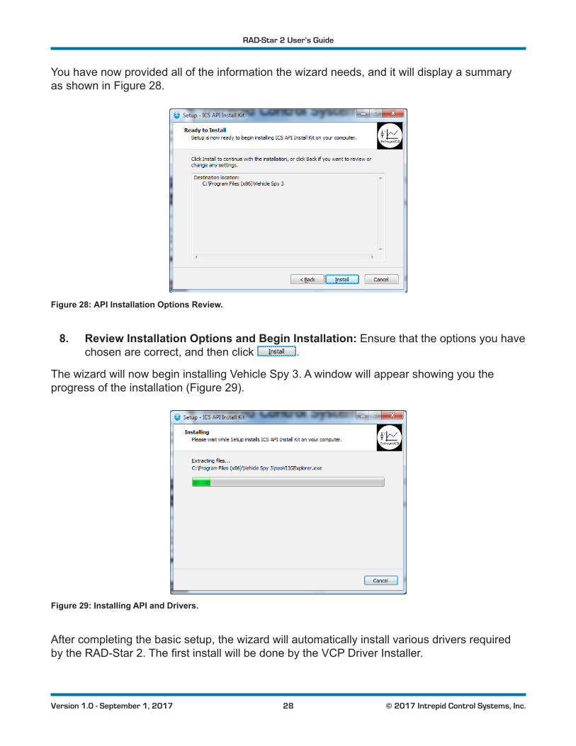
You have now provided all of the information the wizard needs, and it will display a summary as shown in Figure 28.
Figure 28: API Installation Options Review.
8. Review Installation Options and Begin Installation: Ensure that the options you have chosen are correct, and then click .
The wizard will now begin installing Vehicle Spy 3. A window will appear showing you the progress of the installation (Figure 29).
Figure 29: Installing API and Drivers.
After completing the basic setup, the wizard will automatically install various drivers required bytheRAD-Star2.ThefirstinstallwillbedonebytheVCPDriverInstaller.

RAD-Star 2 User’s Guide
29 © 2017 Intrepid Control Systems, Inc.Version 1.0 - September 1, 2017
9. Install VCP Drivers: Click tobegininstallingthefirstsetofdrivers.Whencompleted, a message will appear like the one in Figure 30. Click .
Figure 30: VCP Driver Installation Complete.
Next,supportfilesforMicrosoftVisualC++2010and2005willbeautomaticallyinstalled,iftheyarenotalreadyonthecomputer.YoumaybrieflyseeadialogboxliketheoneinFigure 31.Ifapromptappearssayingthefilesarealreadyinstalled,hit to continue.
Figure 31: Installing Support Files for Microsoft Visual C++ 2005.
Another ICS driver installer dialog box will appear now.
10. Install ICS Port Drivers: Click to begin installing the ICS port drivers.
If you see a Windows dialog like the one in Figure 32, click to authorize installation.
Figure 32: Windows Security Dialog Box.

RAD-Star 2 User’s Guide
30 © 2017 Intrepid Control Systems, Inc.Version 1.0 - September 1, 2017
Once installation begins, it will take only a few seconds, and when completed, a message will appear like the one in Figure 33.
11. Complete Port Driver Installation: Click to exit this part of the install.
Figure 33: Port Driver Installation Complete.
You will now see a dialog box like the one shown in Figure 34, indicating that the setup process is complete.
Figure 34: Vehicle Spy 3 Setup Complete.
12. Exit the Setup Wizard: Click .
Congratulations, you’re done!

RAD-Star 2 User’s Guide
31 © 2017 Intrepid Control Systems, Inc.Version 1.0 - September 1, 2017
3.3 Hardware Hookup Diagrams
The hookup diagrams below show you at a glance how to physically connect your RAD-Star 2 toyourvehiclenetworksandPC.Theexactconfigurationdependsonhowyouareusingthedevice, but since its operation is relatively straightforward, hardware hookup is quite easy.
Standard Active Tap and Media Converter Hardware Hookup Diagram
Figure 35 shows the basic hookup of components for the RAD-Star 2 when used in its normal active tap or media converter modes. In active tap mode, naturally, both AE nodes must be connected; when using the device as a media converter, you can connect one or two nodes. Either the Ethernet or USB connection to the PC can be used, but not both at the same time.
AENode 1
12V
CAN/LINNetworks
AENode 2
OR
Figure 35: RAD-Star 2 Standard Active Tap and Media Converter Hookup Diagram.
Raw Media Converter Hardware Hookup Diagram
Figure 36 is the same as Figure 35butmodifiedslightlytoshowtherelevantconnectionsinraw converter mode. As described earlier, in this mode only one Automotive Ethernet channel (BR1) is enabled in the RAD-Star 2, and only the Ethernet link to the PC may be used.
AENode
12V
CAN/LINNetworks
Figure 36: RAD-Star 2 Raw Media Converter Hookup Diagram.

RAD-Star 2 User’s Guide
32 © 2017 Intrepid Control Systems, Inc.Version 1.0 - September 1, 2017
3.4 Vehicle Network and Power Connections
Let’s start our hardware connections by attaching the RAD-Star 2 to its power supply and the vehicle networks it will monitor. Please follow these steps.
1. Connect the Power Supply: Plug the included power supply into a standard wall outlet, then attach the barrel connector to the mating connector on the left side of the RAD-Star 2. You should immediately see an LED begin blinking on the top surface of the device.
If you are using a different means of providing DC power to the RAD-Star 2, then make the appropriate connections instead.
2. Attach BroadR-Reach Cable Nano MQS Connector to RAD-Star 2: Carefully slide the Nano MQS plug of the cable assembly you created for BroadR-Reach into the matching socket on the RAD-Star 2. The connectors are keyed, and you should hear a slight click when the plug is correctly seated. Notice the release tab, which you will use if you want to remove the connector later on.
3. Connect BroadR-Reach Cable to Automotive Ethernet Nodes: Attach the terminated endsoftheNanoMQScableassemblytotheappropriateECUsand/orswitchports.The exact means of doing this will depend on how the wires are terminated, and whether you are using the device as an active tap or a media converter. Remember that in raw media converter mode, only the BR1 channel is operational.
4. (Optional) Connect Conventional Vehicle Networks: If using the RAD-Star 2’s CAN (and in the future, LIN) channels, attach the appropriate cable to your network and to the RAD-Star 2’s DB-9 connector.
The RAD-Star 2 should now be fully connected to your vehicle or bench network.
3.5 PC Connection
Now we are ready to connect the RAD-Star 2 to the PC. Since all data is conveyed over a single link, this is quite straightforward:
• Ethernet Link: If using Ethernet to connect to your PC, connect one end of the included Ethernet cable to the RAD-Star 2 and the other to the Ethernet port of your PC.
Note: The RAD-Star 2 was designed to be connected directly to a PC Ethernet port. Intrepid does not support using a
conventional Ethernet switch between the RAD-Star 2 and the PC.

RAD-Star 2 User’s Guide
33 © 2017 Intrepid Control Systems, Inc.Version 1.0 - September 1, 2017
If the supplied Ethernet cables are too short for your application, you can use a longer one, as longasitiscertifiedforGigabitEthernetoperation.
SincetheRAD-Star2iscapableoftransmittingupto200Mb/sofdatabidirectionally,westronglyrecommendusingaPCwithaGigabitEthernetcontroller.A100Mb/sEthernetconnectionmaybesufficient,however,forlow-bandwidthapplications.
• USB Link: If using USB to connect to your PC, attach one end of a standard USB 2.0 “A/B”cabletotheRAD-Star2andtheothertoaUSBportonyourPC.
Again, remember that USB cannot be used for raw media converter mode.

RAD-Star 2 User’s Guide
34 © 2017 Intrepid Control Systems, Inc.Version 1.0 - September 1, 2017
4 Device ConfigurationYour RAD-Star 2 ships from the factory ready to use with its default settings. Note that sinceitsprimaryfunctionistoserveasanactivetap,itisconfiguredbydefaulttoruninthatmode. However, its operation can also be customized to your exact needs by adjusting many parametersthatcontrolitsinternalhardwareandfirmware.Inthischapter,we’llshowyouhowtomanageandfine-tuneyourRAD-Star2,includingswitchingbetweenactivetapandmediaconvertermodesandturningonoroffspecificfeatures.
4.1 Starting and Using neoVI Explorer
The neoVI Explorerutilityallowsyoutoconnectto,manageandconfigureallofyourIntrepidControl Systems hardware, including the RAD-Star 2. It is supplied both as an integrated feature of Vehicle Spy, and as a standalone program.
This section will describe general features and the basics of using neoVI Explorer, so you will understandtheutilitywhenwegetintosettingsspecifictotheRAD-Star2.
Starting neoVI Explorer from within Vehicle Spy
There are several ways to open neoVI Explorer from within VSpy. These are probably the two easiest, since they are accessible at all times:
• Menu Item: Click the Setup menu and then select Hardware.
• Hardware Setup Button: Click the button located in the main Vehicle Spy toolbar just under its menu (Figure 37).
Figure 37: Starting neoVI Explorer from within Vehicle Spy.
Note that you cannot start neoVI Explorer when Vehicle Spy is online (even if in simulation mode).Ifyouattempttodoso,VSpywillpromptyoutoeithergoofflineandlaunchneoVIExplorer, or remain online and return to Vehicle Spy.
Starting neoVI Explorer as a Standalone Program
If you want to work with your RAD-Star 2 without opening Vehicle Spy, you can launch neoVI Explorer directly. Open the Start Menu, navigate to the IntrepidCS folder, then under the Vehicle Spy 3 subfolder, select neoVI Explorer (Figure 38).

RAD-Star 2 User’s Guide
35 © 2017 Intrepid Control Systems, Inc.Version 1.0 - September 1, 2017
Figure 38: Starting neoVI Explorer Directly.
Starting neoVI Explorer as a Standalone Program (API Kit Installed)
IfyouinstalledtheAPIkitandsupportfilesinsteadofVehicleSpy,youcanrunneoVIExplorerfrom the Start Menu using the same basic process as described above. The only difference is the name of the subfolder, so you will navigate to the IntrepidCS folder, then open the ICS API Install Kitsubfolder,andfinallyselectneoVI Explorer (Figure 39).
Figure 39: Starting neoVI Explorer as a Standalone Program from the API Kit.
Connecting to the RAD-Star 2
WhenneoVIExplorerloads,itwillstartupwiththefirsthardwaredeviceitcanfindselectedin the menu pane on the left. You should see your RAD-Star 2 listed here, along with its serial number, which begins with “RS”. If you don’t see the RAD-Star 2, but do see other Intrepid devices, be sure to scroll down to look for it. If it is still not visible, this means its drivers have not been installed correctly, it is not powered properly, or it is not connected to the PC’s Ethernet or USB port. Please contact Intrepid for assistance, if needed.

RAD-Star 2 User’s Guide
36 © 2017 Intrepid Control Systems, Inc.Version 1.0 - September 1, 2017
To manage your RAD-Star 2, click on its entry in the navigation pane (if it is not already highlighted) and then press the Connect button. After successfully connecting to the device, you will see a “thumbs up” icon next to the device’s name, and checkmarks will appear next to currently-enabled networks in the explorer area on the left. You should also see a message in the message box on the right saying “RADStar2 RSxxxx settings have been read”. This tells you that neoVI Explorer has loaded the current settings from the unit. The information in the upperright-handpartofthewindowisdevice-specificanddescribedinSection 4.2. The screen as a whole should appear similar to that shown in Figure 40 (but note that the version number shown at the bottom may be different).
Figure 40: Typical neoVI Explorer Window After Initial Connection to the RAD-Star 2.
Writing and Reloading Settings
To avoid potential problems, neoVI Explorer will not save any changes to device parameters until you instruct it to do so. This is done by pressing the Write Settings button, which will updatetheparameterswithinthefirmwareinyourRAD-Star2.Ifyoumakechangesyoudo not want to keep, pressing the Read Settings button will reload the settings stored in the device,wipingoutanymodificationsmadeinneoVIExplorerthathadnotyetbeensaved.
Reloading Device Defaults
To return all settings to factory defaults, press the Load Default Settings button. This is convenientifmanychangeshavebeenmadeandwrittentothefirmwareinthepast,andyouwant to start over with a clean slate.

RAD-Star 2 User’s Guide
37 © 2017 Intrepid Control Systems, Inc.Version 1.0 - September 1, 2017
Notethatpressingthisbuttonactuallywritesthedefaultstothedevicefirst,andthenreloadsthem automatically, so you do not need to also press Write Settings. You will see messages in the message area telling you that defaults have been sent to the device and then read from it.
Disconnecting from the RAD-Star 2
Press the Disconnect button to tell neoVI Explorer that you are done working with the RAD-Star 2. This step is not required if you are simply done with neoVI Explorer and want to exit, but is necessary before connecting to another device.
Searching for Devices
If you attach new hardware to your PC after starting neoVI Explorer, press the Search For Devices button at the bottom left of the dialog box to prompt the program to scan for new hardware you can manage.
Exiting neoVI Explorer
Like any Windows program, you can close neoVI Explorer by clicking the “X” in the top right corner, or pressing the Alt+F4 key combination.
4.2 System Settings and Firmware Updates
The top two entries in the explorer window on the left side of neoVI Explorer contain system-widesettingsthatapplytoallhardwaredevices,andinformationrelatedtofirmwareupdates.
System Settings
Click here, and in the right-hand pane you will see three settings that you can enable or disable (Figure 41):
• Enable Server: Turns on the neoVI Server feature, a background program that allows your hardware to be used by multiple applications at the same time.
• Enable Low Latency: This is an advanced setting for applications where fast response is needed after transmission.
• Enable Auto Update: When enabled, both neoVI Explorer and Vehicle Spy will automaticallyupdatefirmware.Ifthisboxisnotchecked,firmwaremustbeupdatedmanually. (See below for details.)

RAD-Star 2 User’s Guide
38 © 2017 Intrepid Control Systems, Inc.Version 1.0 - September 1, 2017
Figure 41: neoVI Explorer System Settings Pane
Available Firmware
ThisisaninformationalpagethatshowswhichfirmwareversionsareavailableinthisversionofneoVIExplorerforvariousIntrepidproducts.Somedeviceshavemultiplefirmwareprogramsthat control different aspects of their operation; in the case of the RAD-Star 2, there is only one, called ZynQ Core.
You normally won’t need to look in this area, because as seen in Figure 40, neoVI Explorer showsyouthecurrentandavailablefirmwareversionsforyourRAD-Star2whenyouconnectto it.
Automatic and Manual Firmware Updates
Firmware is essentially software that runs hardware, and is required to enable the many capabilitiesofyourRAD-Star2.NewversionsoffirmwarearecreatedregularlybyIntrepid’sengineerstoimplementnewfeaturesandcorrectproblemsthathavebeenidentified.
If you have Enable Auto Update on—which is the default, and is recommended—then you don’treallyneedtoworryaboutfirmwareupdates.EachtimeyouconnecttoyourRAD-Star2inneoVIExplorerorgoonlinewithitinVehicleSpy,thefirmwarewillbechecked,andifanewer version is available, the device will immediately be updated.
Ifyoudonothaveautomaticupdatesenabled,youcontrolwhenyourfirmwareisupdated.Whennewfirmwareisavailable,youwillbenotifiedontheinitialconnectionscreen,asshownin Figure 42. Simply press the Manual Reflashbuttontoupdatethefirmware.
Note: Firmware updates are not supported over USB at this time. If you normally use USB to connect to the RAD-Star 2,
you will need to temporarily connect using Ethernet to perform firmwareupgrades.This limitationshouldbe removed ina futurefirmware version of the RAD-Star 2 (which will itself, of course,requireafirmwareupgrade!)

RAD-Star 2 User’s Guide
39 © 2017 Intrepid Control Systems, Inc.Version 1.0 - September 1, 2017
Figure 42: neoVI Explorer Firmware Message Box and Manual Reflash Button.
The Firmware Update Process
Duringthefirmwareupdateprocess,theRAD-Star2willbeplacedintobootloader mode, indicatedbyallofitsLEDsflashingbluesynchronously.(Thedevice’snormalLEDflashpatterns will resume when the update is complete and the device reboots.)
Youwillseeadialogboxonthescreenshowingyoutheprogressofthefirmwareupdateoperation, which takes about a minute; an example is shown in Figure 43. You will also see messagesinthemessageboxontherightsideofneoVIExplorerastheZynQCorefirmwareprogram is sent to the device. When the process is complete the dialog box will disappear and anothermessagewillappearinneoVIExplorertoconfirmthattheupdatehasfinished.
If you receive any error messages or experience any other problems updating your RAD-Star 2’sfirmware,pleasecontactIntrepidforassistance(seeChapter 6).
Figure 43: RAD-Star 2 Firmware Update Message Box.

RAD-Star 2 User’s Guide
40 © 2017 Intrepid Control Systems, Inc.Version 1.0 - September 1, 2017
Warning: Please take heed of thewarning on the firmwareupdate dialog box: leave the RAD-Star 2 connected and
poweredonfortheentirefirmwareupdateprocesstoavoidpossibleproblems with the device.
4.3 General Settings and Product Details
These two areas of the RAD-Star 2’s parameter setup provide information about the device and allow you to perform a few basic maintenance tasks.
General Settings
After connecting to the device you will see basic information about it in the right-hand pane of the window:
• The device’s serial number.
• Thefirmwareversionscurrentlyinthedevice,andanindicationifnewfirmwareisavailable.
• A message showing that the hardware license for the device was recognized.
This information can be displayed again at any time by clicking the RAD-Star 2’s name in the explorer navigation window, or the General Settings entry immediately below it.
TheversionoftheZynQCorefirmwarefortheRAD-Star2willbeshowninblackifitmatchesthefirmwareversionwithinneoVIExplorer.Ifnot,thecurrentversionandthenewestavailableversion will be shown in red to help you notice that an update is available, as seen in Figure 42. Section 4.2providesmoreinformationonfirmwareupdates.
Product Details
This is an informational area that provides technical data on the RAD-Star 2’s hardware and internal setup. You will generally only need this if requested by Intrepid in order to facilitate support or troubleshooting. You can use the Copy To Clipboard button to copy all of the informationtotheWindowsClipboard,soyoucanthenpasteitintoanemailorfile.
4.4 Standard CAN Networks (HS CAN and MS CAN)
ThisareaofneoVIExplorerisusedtoenable,disableandconfigurethetwostandarddualwireCAN networks in the RAD-Star 2: the High Speed CAN channel (HS CAN) and the Medium Speed CAN channel (MS CAN). Each channel has an entry under the “CAN” group (which

RAD-Star 2 User’s Guide
41 © 2017 Intrepid Control Systems, Inc.Version 1.0 - September 1, 2017
cannot be clicked itself). The current status of each channel is shown next to its name; a green checkmark indicates that the channel is enabled, while a red X means it is disabled. Figure 44 shows an example of the CAN channels area, with both channels enabled.
Figure 44: neoVI Explorer CAN Group.
Note: The names of the channels may differ from one place to another in your hardware and software. “HS CAN” and “CAN 1”
bothrefertothefirstCANchannel,while“MSCAN”and“CAN2”mean the second CAN channel.
Bothofthesechannelshavethesameparameters,whichcanbeconfiguredusingthecontrolsin the right-hand pane; the default settings are shown in Figure 45.
Figure 45: neoVI Explorer Standard CAN Parameters with Default Settings.
Enabled
Place a checkmark in this box to enable the channel, or clear the checkmark to disable it. When disabled, all of the other parameter controls are disabled (grayed out).
HS CAN / MS CAN Settings
The settings on the left side of the parameter area are for normal (non-FD) CAN operation.

RAD-Star 2 User’s Guide
42 © 2017 Intrepid Control Systems, Inc.Version 1.0 - September 1, 2017
Specify by Baud
This is a master control that determines whether the operation of the channel is controlled by a numeric baud rate, or is calculated from lower-level timing parameters. When checked, the Baud Rate drop-down boxes for both CAN and CAN FD are enabled and the relevant TQ, Sync and BRP-1 entries are disabled. When unchecked, this is reversed.
Specifying by baud rate is the default, and is recommended except for advanced users with special requirements.
Baud Rate
When Specify by Baud is selected, choose a baud rate for the channel from the drop-down box below. The default value is 500000.
CAN Timing Settings
When Specify by Baudisdeselected,theoperationoftheCANchannelisbasedonthesefivesettings: TQ SEG1, TQ SEG2, TQ Prop, Sync, BRP-1. These settings are for advanced users and normally should be left at their default values.
Bit Rate Calculator
Press this button to launch the Intrepid Bit Timing Calculator.
CAN FD Settings
The settings on the right side of the parameter area control CAN FD operation.
CAN FD Baud Rate
When Specify by Baud is selected, choose a baud rate for the data phase of CAN FD messages. The default value is 2000000.
CAN FD Timing Settings
When Specify by Baud is deselected, use these settings (TQ SEG1, TQ SEG2, TQ Prop, Sync, BRP-1) for the data phase of CAN FD messages. These parameters are for advanced users and normally should be left at their default values.
ISO
Check this box to enable ISO-compliant CAN FD operation.

RAD-Star 2 User’s Guide
43 © 2017 Intrepid Control Systems, Inc.Version 1.0 - September 1, 2017
4.5 LIN Network (LIN)
This section will be detailed in a future version of the manual, once the LIN channel on the RAD-Star 2 is functional.
4.6 One Pair Ethernet (BroadR) Automotive Ethernet Networks
This is the section of neoVI Explorer that is arguably the most important for the RAD-Star 2, since it controls the operation of the device’s BroadR-Reach (100BASE-T1 compatible) Automotive Ethernet channels. Overall control parameters are found within the parent One Pair Ethernet (BroadR) entry, while those for the individual channels are located in the subordinate OP (BR) ETH1 and OP (BR) ETH2 entries, as shown in Figure 46.
Figure 46: neoVI Explorer Automotive Ethernet Parameter Group.
One Pair Ethernet (BroadR)
This area contains a small number of parameters that affect the overall operation of the RAD-Star 2’s Ethernet channels (see Figure 47).
Figure 47: neoVI Explorer One Pair Ethernet (BroadR) General Parameters.
BroadR Port Function
Use this dropdown box to select the primary mode of operation of the RAD-Star 2 (please refer back to Section 1.3 for more detailed explanations of these modes). This box only controls the operationofthedevicewhenitissettonormalmodeoperation,indicatedbyflashinggreenorblueLEDsinthe“BR”or“CANLIN”buttonsontopofthedevice.IftheLEDisflashingwhite,the device is in raw media converter mode, and this setting is ignored; please see Section 2.2 for more information.

RAD-Star 2 User’s Guide
44 © 2017 Intrepid Control Systems, Inc.Version 1.0 - September 1, 2017
The three settings here are:
• Tap: The RAD-Star 2 behaves as an active tap.
• Media Converter:TheRAD-Star2isconfiguredasa“normal”mediaconverter(support for two connected devices).
• Tap - Low Latency: The RAD-Star 2 behaves as an active tap but with “cut-through” operation.
The standard operating mode of the RAD-Star 2 is called “store and forward,” which means that each packet is received by the device and then retransmitted where it needs to go. In contrast, “cut-through” means that the frame starts being retransmitted as soon as possible, before it has been fully received.
Cut-through operation provides lower latency operation, since frames are retransmitted more quickly. However, there are some limitations: there’s no buffering of frames and you cannot transmit from the PC to attached devices in this mode.
Tap Options - Enable Switch Mode
This is present only when the parameter above is set to Tap. It is reserved for future functionalityandcurrentlydoesnotaffecttheoperationofthedevice.(Notespecificallythatthis does not cause the RAD-Star 2 to behave as an Ethernet switch.)
OP (BR) ETH1 and OP (BR) ETH2
Each of these entries contains the same parameters and controls the corresponding BroadR-Reach channel on the RAD-Star 2 (Figure 48).
Figure 48: neoVI Explorer OP (BR) Automotive Ethernet Channel Parameters.
Enabled
Placing a checkmark in this box enables the channel, while clearing the checkmark disables it. When disabled, the Link Mode parameter is disabled (grayed out).

RAD-Star 2 User’s Guide
45 © 2017 Intrepid Control Systems, Inc.Version 1.0 - September 1, 2017
Link Mode
Provides control over link negotiation for the channel. Automotive Ethernet requires each link tohaveonedeviceconfiguredasmasterandtheotherasslave:thePHYofthemasterdevicegenerates a shared clock signal for the channel, and the slave device’s PHY synchronizes to it.
By default, the RAD-Star 2 will automatically adjust to complement the settings of the devices connected to its channels. However, if necessary, you can use these settings to manually override this behavior:
• Auto:TheRAD-Star2willautomaticallyconfigureitselfasmasterorslaveasrequiredto establish a link to the other device on this channel.
• Master: This channel will always act as a master device.
• Slave: This channel will always act as a slave device.
AutomaticconfigurationisaccomplishedbyalternatingtheinternalconfigurationofthePHYbetween master and slave and continuously attempting to establish a connection with the linked device using both settings. In this manner, the RAD-Star 2 will link with the other device whether it is set to master or slave. (The autonegotiation feature in conventional Ethernet that allowsPHYstocommunicatetheirmaster/slavesettingsdoesnotexistinBroadR-Reach.)
Note that the designation of a device as master or slave only matters for low-level clock synchronization as described above. Aside from this, the devices are peers on the network; in particular, the master does not control operation of the slave.
Preemption Support (IEEE802.3br)
Click this checkbox to enable frame preemption support for the associated channel, as described in IEEE standard 802.3br.
4.7 Time Sync ICS Hardware
These settings are used to enable time synchronization between multiple Intrepid hardware devices. This section will be described in more detail in a future version of this manual.
4.8 Network Enables
This area provides more options for enabling and disabling individual networks within the RAD-Star 2 (Figure 49). The main display contains a scrollable list with checkboxes that can be set or unset to enable or disable each network. These are equivalent to the Enable checkboxes found in the parameter areas for the corresponding networks.
This list contains all of the networks supported by all Intrepid devices. By default, networks not present on the RAD-Star 2 are disabled.

RAD-Star 2 User’s Guide
46 © 2017 Intrepid Control Systems, Inc.Version 1.0 - September 1, 2017
Figure 49: neoVI Explorer Network Enable/Disable Parameters.
Enable On Boot
Normally, the RAD-Star 2 will not acknowledge messages on a network unless it is online with that network. When this option is enabled, the device always acknowledges frames on all enabled networks.
Send Bus Traffic to Android
This setting is not applicable to the RAD-Star 2 and can be ignored.
Enable All
Enables all networks. Pressing this button will attempt to set checkmarks for all networks; if you use it, be sure to disable networks that should be off, so the device remains in a valid configuration.
Disable All
Disables all networks.

RAD-Star 2 User’s Guide
47 © 2017 Intrepid Control Systems, Inc.Version 1.0 - September 1, 2017
5 Reference: Connector PinoutsThis chapter contains pinout information for the vehicle interface connectors on the RAD-Star 2. For your convenience, this information is also printed on the bottom of the device.
Note that the connectors for linking the RAD-Star 2 to the PC are not described here since they are industry standard (Gigabit Ethernet and USB).
5.1 BroadR-Reach Nano MQS Connector Pinout
The pinout of the RAD-Star 2’s BroadR-Reach (“BR”) connector can be found in Table 1. A close-up of the connector is shown in Figure 50.
Pin # Label Description1 DNC Do not connect
2 DNC Do not connect
3 BR1- BroadR-Reach channel 1, negative
4 BR1+ BroadR-Reach channel 1, positive
5 DNC Do not connect
6 DNC Do not connect
7 BR2- BroadR-Reach channel 2, negative
8 BR2+ BroadR-Reach channel 2, positive
Table 1: BroadR-Reach Nano MQS Pinout Details.
Figure 50: BroadR-Reach Nano MQS Connector with Pin Assignments.
5.2 DB-9 Conventional Network Interface Connector Pinout
See Table 2forthedetailsontheRAD-Star2’sconventionalnetwork(“CAN/LIN”)DB-9connector, and refer to Figure 51 for a close-up of the connector and its pin assignments.

RAD-Star 2 User’s Guide
48 © 2017 Intrepid Control Systems, Inc.Version 1.0 - September 1, 2017
Pin # Label Description1 LIN 1 LIN channel (future)
2 CAN 1 L High Speed CAN channel, low
3 GND Ground
4 CAN 2 L Medium Speed CAN channel, low
5 GND Ground
6 GND Ground
7 CAN 1 H High Speed CAN channel, high
8 CAN 2 H Medium Speed CAN channel, low
9 VBATT DC power input
Table 2: Conventional Network (CAN/LIN) DB-9 Connector Pinout Details.
Figure 51: Conventional Network (CAN/LIN) DB-9 Connector with Pin Assignments.

RAD-Star 2 User’s Guide
49 © 2017 Intrepid Control Systems, Inc.Version 1.0 - September 1, 2017
6 Support Contact InformationIf you have a problem you cannot resolve on your own, feel free to contact ICS for assistance atoneofouroffices.
Notethatproblemswiththedevicecansometimesberesolvedthroughfirmwareupdates,which are covered in Section 4.2.
6.1 ICS United States Headquarters
Our primary support personnel can be reached at our American headquarters in the Detroit area, using the following contact information:
• Phone: (800) 859-6265 or (586) 731-7950, extension 1.
• Fax: (586) 731-2274.
• Email: [email protected]
Intrepid’s normal support hours are from 8 am to 5 pm, Monday to Friday, United States Eastern time. If you require assistance outside standard business hours, feel free to contact us and a member of our support team will get back to you as soon as possible.
6.2 ICS International Offices
European Union Office
ForsupportintheEU,pleasecontactIntrepid’sGermanyoffice:
• Phone: +49 721 6633703 -4.
• Fax: +49 721 6633703 -9.
• Email: [email protected]
Japan Office
Intrepid’sofficeinYokohamacanbereachedasfollows:
• Phone: +81-(0)45- 263-9294.
• Mobile Phone: 080-8884-0111.
• Fax: 045-263-9296.
• Email: [email protected]

RAD-Star 2 User’s Guide
50 © 2017 Intrepid Control Systems, Inc.Version 1.0 - September 1, 2017
Korea Office
In Korea, use the following contact information:
• Phone: +82 31 698 3460.
• Fax: +82 31 698 3461.
• Email: [email protected]
China Office
Intrepid’sShanghaiofficecanalsobereachedbyphone,faxoremail:
• Phone: +86 4006151011.
• Fax: +86 021-51330271-601.
• Email: [email protected]
We can also be contacted in Shenzhen:
• Phone: +86 0755-82723212.
• Email: [email protected]
India Office
In India, please use this contact information:
• Phone: +91 +97 66 44 55 33.
• Email: [email protected]
Australia Office
OurAustralianofficecanbereachedasfollows:
• Phone: 03 9466 4948 (international callers: +61 3 9466 4948).
• Email: [email protected]