racer owners manual june 2015.vp:corelventura...
TRANSCRIPT

SERIAL #
SST/Racer®
OWNERS MANUALRacer/2K3™, Racer/Elite™, SST/Racer, Racer/Trainer,
Racer/Tandem, Racer/Tactical, AngelFire/Nighthawk Reserve
PARACHUTE LABORATORIES INC.
1665 LEXINGTON AVE.
SUITE 106
DELAND, FL. USA
32724
Art work by Nancy LaRiviere & Sandy Williams

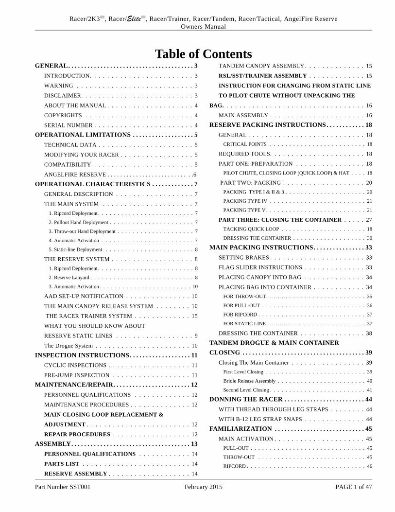
Ta ble of Con tentsGENERAL. . . . . . . . . . . . . . . . . . . . . . . . . . . . . . . . . . . . . . . 3
INTRODUCTION. . . . . . . . . . . . . . . . . . . . . . . . 3
WARNING . . . . . . . . . . . . . . . . . . . . . . . . . . . 3
DISCLAIMER. . . . . . . . . . . . . . . . . . . . . . . . . . 3
ABOUT THE MANUAL . . . . . . . . . . . . . . . . . . . . 4
COPYRIGHTS . . . . . . . . . . . . . . . . . . . . . . . . . 4
SERIAL NUMBER . . . . . . . . . . . . . . . . . . . . . . . 4
OPERATIONAL LIMITATIONS . . . . . . . . . . . . . . . . . . . 5TECHNICAL DATA . . . . . . . . . . . . . . . . . . . . . . 5
MODIFYING YOUR RACER . . . . . . . . . . . . . . . . . 5
COMPATIBILITY . . . . . . . . . . . . . . . . . . . . . . . 5
ANGELFIRE RESERVE . . . . . . . . . . . . . . . . . . . . . . . . . . .6
OPERATIONAL CHARACTERISTICS . . . . . . . . . . . . . 7GENERAL DESCRIPTION . . . . . . . . . . . . . . . . . . 7
THE MAIN SYSTEM . . . . . . . . . . . . . . . . . . . . . 71. Rip cord De ploy ment . . . . . . . . . . . . . . . . . . . . . . . . . 7
2. Pull out Hand De ploy ment . . . . . . . . . . . . . . . . . . . . . . 7
3. Throw- out Hand De ploy ment . . . . . . . . . . . . . . . . . . . . 7
4. Auto mat ic Ac ti va tion . . . . . . . . . . . . . . . . . . . . . . . . 7
5. Static- line De ploy ment . . . . . . . . . . . . . . . . . . . . . . . 8
THE RESERVE SYSTEM . . . . . . . . . . . . . . . . . . . 81. Rip cord De ploy ment . . . . . . . . . . . . . . . . . . . . . . . . . 8
2. Re serve Lan yard . . . . . . . . . . . . . . . . . . . . . . . . . . . 8
3. Auto mat ic Ac ti va tion . . . . . . . . . . . . . . . . . . . . . . . . 10
AAD SET-UP NOTIFICATION . . . . . . . . . . . . . . . 10
THE MAIN CANOPY RELEASE SYSTEM . . . . . . . . 10
THE RACER TRAINER SYSTEM . . . . . . . . . . . . . 15
WHAT YOU SHOULD KNOW ABOUT
RESERVE STATIC LINES . . . . . . . . . . . . . . . . . . 9
The Drogue Sys tem . . . . . . . . . . . . . . . . . . . . . . 10
INSPECTION INSTRUCTIONS. . . . . . . . . . . . . . . . . . . 11CYCLIC INSPECTIONS . . . . . . . . . . . . . . . . . . . 11
PRE-JUMP INSPECTION . . . . . . . . . . . . . . . . . . 11
MAIN TE NANCE/RE PAIR. . . . . . . . . . . . . . . . . . . . . . . . 12PERSONNEL QUALIFICATIONS . . . . . . . . . . . . . 12
MAINTENANCE PROCEDURES . . . . . . . . . . . . . . 12
MAIN CLOSING LOOP REPLACEMENT &
ADJUSTMENT . . . . . . . . . . . . . . . . . . . . . . . . 12
REPAIR PROCEDURES . . . . . . . . . . . . . . . . . . 12
ASSEMBLY. . . . . . . . . . . . . . . . . . . . . . . . . . . . . . . . . . . . . 13PERSONNEL QUALIFICATIONS . . . . . . . . . . . . 14
PARTS LIST . . . . . . . . . . . . . . . . . . . . . . . . . 14
RESERVE ASSEMBLY . . . . . . . . . . . . . . . . . . . 14
TANDEM CANOPY ASSEMBLY . . . . . . . . . . . . . . 15
RSL/SST/TRAINER ASSEMBLY . . . . . . . . . . . . . 15
INSTRUCTION FOR CHANGING FROM STATIC LINE
TO PI LOT CHUTE WITH OUT UN PACK ING THE
BAG. . . . . . . . . . . . . . . . . . . . . . . . . . . . . . . . . 16
MAIN ASSEMBLY . . . . . . . . . . . . . . . . . . . . . . 16
RESERVE PACKING INSTRUCTIONS. . . . . . . . . . . . 18GENERAL . . . . . . . . . . . . . . . . . . . . . . . . . . . 18
CRITI CAL POINTS . . . . . . . . . . . . . . . . . . . . . . . . . 18
REQUIRED TOOLS. . . . . . . . . . . . . . . . . . . . . . 18
PART ONE: PREPARATION . . . . . . . . . . . . . . . . 18PI LOT CHUTE, CLOS ING LOOP (QUICK LOOP) & HAT . . . . 18
PART TWO: PACKING . . . . . . . . . . . . . . . . . . . 20PACK ING TYPE I & II & 3 . . . . . . . . . . . . . . . . . . . . . 20
PACK ING TYPE IV . . . . . . . . . . . . . . . . . . . . . . . . . 21
PACK ING TYPE V . . . . . . . . . . . . . . . . . . . . . . . . . . 21
PART THREE: CLOSING THE CONTAINER . . . . . 27TACK ING QUICK LOOP . . . . . . . . . . . . . . . . . . . . . . 18
DRESS ING THE CON TAINER . . . . . . . . . . . . . . . . . . . 30
MAIN PACKING INSTRUCTIONS. . . . . . . . . . . . . . . . 33SETTING BRAKES . . . . . . . . . . . . . . . . . . . . . . 33
FLAG SLIDER INSTRUCTIONS . . . . . . . . . . . . . . 33
PLACING CANOPY INTO BAG . . . . . . . . . . . . . . 34
PLACING BAG INTO CONTAINER . . . . . . . . . . . . 34FOR THROW- OUT. . . . . . . . . . . . . . . . . . . . . . . . . . 35
FOR PULL- OUT . . . . . . . . . . . . . . . . . . . . . . . . . . . 36
FOR RIP CORD . . . . . . . . . . . . . . . . . . . . . . . . . . . . 37
FOR STATIC LINE . . . . . . . . . . . . . . . . . . . . . . . . . 37
DRESSING THE CONTAINER . . . . . . . . . . . . . . . 38
TAN DEM DROGUE & MAIN CON TAINERCLOS ING . . . . . . . . . . . . . . . . . . . . . . . . . . . . . . . . . . . . . . 39
Clos ing The Main Con tainer . . . . . . . . . . . . . . . . . 39First Level Clos ing . . . . . . . . . . . . . . . . . . . . . . . . . . 39
Bri dle Re lease As sem bly . . . . . . . . . . . . . . . . . . . . . . . 40
Sec ond Level Clos ing . . . . . . . . . . . . . . . . . . . . . . . . . 41
DONNING THE RACER . . . . . . . . . . . . . . . . . . . . . . . . . 44WITH THREAD THROUGH LEG STRAPS . . . . . . . . 44
WITH B-12 LEG STRAP SNAPS . . . . . . . . . . . . . . 44
FAMILIARIZATION . . . . . . . . . . . . . . . . . . . . . . . . . . . . 45MAIN ACTIVATION . . . . . . . . . . . . . . . . . . . . . 45
PULL- OUT . . . . . . . . . . . . . . . . . . . . . . . . . . . . . . 45
THROW- OUT . . . . . . . . . . . . . . . . . . . . . . . . . . . . 45
RIP CORD . . . . . . . . . . . . . . . . . . . . . . . . . . . . . . . 46
Part Num ber SST001 Feb ru ary 2015 PAGE 1 of 47
Racer/2K3 , Racer/Elite , Racer/Trainer, Racer/Tan dem, Racer/Tac ti cal, An gel Fire ReserveOwn ers Man ual

C U T A W A Y A C T I V A T I O N. . . . . . . . . . . . . . . . . 46 RESERVE ACTIVATION . . . . . . . . . . . . . . . . . . 46
Racer/2K3 , Racer/Elite , SST/Trainer, Racer/Tan dem, Racer/Tac ti cal, An gel Fire ReserveOwn ers Man ual
Part Num ber SST001 Feb ru ary 2015 Page2 of 47.

GENERAL
INTRODUCTION
Congratulations on the purchase of your new Racer,
Racer Trainer or Racer Tandem System. As you put
jumps on your new rig and get to know it, you will
come to realize that you have purchased the most
exquisite piece of parachute equipment that money
can buy. We are sure that it is the most thoroughly
engineered harness and container system available.
Note our attention to details such as our use of type
13 webbing, the only webbing approved for use
with all parachute hardware. The new 2K3™
features magnetic riser covers and Anti-Line-Strip
main and reserve deployment bags . We’ve paid at-
tention to important details like our High Drag
Pilotchutes, but many features of the Racer will es-
cape your first glance.
We started building SSTs when the idea of “piggy-
back” meant literally snapping a reserve to your
back above the main container. We developed and
were the first to employ the hot knifed single piece
construction technique now used by all of the other
manufacturers. Now after 46 years and 45,000 Rac-
ers, our basic design hasn’t had to change much. It
was ahead of its time when it was conceived and it
still is. So while other manufacturers have had to
undergo recalls and major design changes in an ef-
fort to “get it right” the Racer has endured. Even
our competitors have said of the Racer, “Sherman
got it right the first time”.
When you examine current production Racers, you
will find the basic workings of the rig haven’t
changed. We’ve just made it simpler and more at-
tractive! Today’s Racer is a refined version of the
most time-proven design in parachuting. We did get
it right the first time.
As parachutes got smaller, we introduced the Power
Racer - the smallest, lightest rig in the world. The
Racer harness and container system fits more like
a tailored coat than a hiker’s backpack. The Racer
offers more deployment options and more sizes than
any other container system.
Only the Racer offers the superior Pop-Top reserve
system, and we still make Racers for the jumper
who demands gear from the cutting edge of skydiv-
ing technology.
This manual introduces you to your new Racer/2K3,
Classic Racer, TRAINER or Racer Tandem. You
must read this manual before taking to the air with
it. So leave yourself plenty of time between getting
the rig and making the first jump on it. Use this
manual to help familiarize yourself with the system.
You can get thousands of jumps from a well main-
tained Racer, so there’s no need to rush to the first
one.
WARNING
IT IS ASSUMED THAT INTENTIONALLY
JUMPING FROM AN AIRPLANE IN FLIGHT
OR FROM A FIXED OBJECT IS DANGEROUS
TO LIFE AND LIMB. PARACHUTES DO NOT
ALWAYS WORK AS DESIRED. WHEN YOU
TAKE IT UPON YOURSELF TO PARTICIPATE
IN PARACHUTE JUMPING, YOU ACCEPT THE
FACT THAT NO MATTER HOW CAREFUL YOU
ARE, OR HOW GOOD YOUR EQUIPMENT IS,
YOU CAN BE SERIOUSLY OR FATALLY IN-
JURED.
WARNING—NO
WARRANTIES
DISCLAIMER
It is expressly understood and agreed between the
seller and the buyer and any subsequent user of the
Racer, all or in part, the manufacturer and seller
shall in no way be deemed or held liable or account-
able for any failure or damages resulting from fail-
ure of the Racer. Use of the Racer for any purpose
shall constitute waiver to the manufacturer and
seller for any damages to person or property directly
or indirectly caused by said use. The Racer is sold
Part Number SST001 February 2015 PAGE 3 of 44
Racer/2K3��
, Racer/Elite��
, Racer/Trainer, Racer/Tandem, Racer/Tactical, AngelFire Reserve
Owners Manual

w i t h a l l f a u l t s a n d w i t h o u t f i t n e s s f o r a n y p a r t i c
pur pose, and the manu fac turer nei ther im plies or ex -presses any war ran ties or guar an tees of the Racer.Use of this rig for any pur pose con sti tutes agree -ment be tween the buyer or user and the seller ac -cord ing to the terms herein. If the buyer re fuses theterms of this agree ment, he must re turn the un usedRacer to the manu fac turer with 10 days of re ceipt of the Racer with a let ter stat ing why the Racer was re -turned along with the origi nal in voice show ing pur -chase price.
ABOUT THE MANUALWe have tried to write this eighth edi tion of theRacer Own ers Man ual, for all models. How ever, itis only cur rent for the se rial number shown on thefirst page. The data con tained herein was cur rent atthe time of this writ ing, but the sport ad vances rap -idly. Some of this in for ma tion may not be true nowor es pe cially as time goes on. We re serve the rightto change the Racer and its pro ce dures with out no -tice. Pru dence re quires that you con tact us for in for -ma tion on up dates if you are us ing this man ual as aguide to serv ice a later gen era tion Racer. Ad di tion -ally, you may view our most re ci ent version at ourInter net site www.jump shack.com or www.plab -sinc.com
COPYRIGHTSPLI holds all copy rights to this man ual. We grantper mis sion to any one to re pro duce it all or in partfor non- commercial pur poses. No re pro duc tion ofthis man ual may be sold any where with out a roy alty agree ment with PLI. Any one copy ing this man ualfor dis tri bu tion must do so with out charge, ex cept -ing the cost of re pro duc tion.
DATE OF MANUFACTURER / SERIAL NUMBER
The se rial number on the data la bel is also the date of manufacture. The first two dig its of the thisnumber de note the week of manu fac ture. The sec -ond two digits de note the year. The last two dig itsde note the se quence of rig that week. For ex am ple,Se rial Num ber 081501 would in di cate a Feb ru ary,2015 date of manu fac ture, and the first rig built thatweek.Prior to Feb ru ary 2009, five- digit se rial num berswere used. Then, the first two dig its in di cated theweek of manu fac ture, the third digit in di cated theyear, and the last two dig its de noted the se quence of rig in that week. One would have to know whichdec ade the rig was manu fac tured in, however. Nowthat PLI is in its fifth dec ade, mak ing Rac ers, wefig ured it was time to sim plify the code by add ing asixth digit.Cau tion: This man ual is se rial num bered cor re -spond ing to the Racer with which it was shipped.Tech ni cal in for ma tion in this man ual re fers only tothe Racer of that same se rial number.Re cord the in for ma tion from the data plate now,along with the col ors of your Racer, in case yourgear be comes lost or sto len. Also rec ord the se rialnum bers and col ors of your main and re serve para -chutes. Keep the rec ord some place other than yourequip ment bag.If you have any ques tion re gard ing the Racer, thisman ual, or the pro ce dures de scribed in the man ual,con tact:
Parachute Labs, Inc.1665 N. Lexington Ave. #106DeLand, Florida 32724 USA
TEL (386) 734-5867FAX (386) 734-8464
Part Num ber SST001 Feb ru ary 2015 Page4 of 47
Racer , Racer/Elite , Racer/Trainer, Racer/Tan dem, Racer/Tac ti cal, An gel Fire Re serveOwn ers Man ual

OPERATIONAL LIMITATIONS
TECHNICAL DATA
The Racer harness and container system has been
certificated in the Standard Category by the Federal
Aviation Administration (FAA) under Technical
Standard Order (TSO) C-23(b). This TSO refers to
National Aircraft Standard (NAS) 804 published in
September, 1949. The Tandem is Certified under
TSO-C23(c). This TSO refers to AS-8015a pub-
lished September 30, 1982. To meet these require-
ments, the manufacturer must submit the design in
drawings to the FAA Engineering District Office.
The FAA then inspects and certifies the manufactur-
ing facility and approves the quality control of the
manufacturing process as described in the manufac-
turer’s manual.
The FAA further assures that the manufacturer will
trace and inspect each piece of fabric and hardware
he uses during the manufacturing process of the
equipment.
Under TSO C-23(b), equipment can be tested to
Standard Category (sometimes called High Speed)
or Low Speed Category. The Racer has been tested
to the Standard Category which certifies it to a
shock load of 5,000 pounds. The rig may be assem-
bled with a Low Speed Category reserve canopy,
but then the entire system becomes certificated in
the Low Speed Category. (Later installation of a
Standard Category canopy restores the system to the
Standard Category, of course.) Regulations require
the rigger to identify the system as Low Speed
Category in the appropriate manner when he installs
a reserve from that category. Standard Category re-
quires no markings. Canopies certificated under
TSO C-23(c), and later revisions may be assembled
into the Racer line of containers providing the as-
sembling rigger has complied with FAA regulations
and policy. Performance limitations of the installed
canopy should be placarded, in the manner required
by the TSO document, for the user’s information.
The Tandem certified under TSO C23(c) must con-
form to AS-8015a . The test weight and speed
specified in AS-8015a Catagory B is 300 Lbs. @
175 KTS. The Racer Tandem system has been
tested to 600 LBS. @ 175 KTS.
Many reserve and main canopies will fit well into
your Racer, but some won’t. Results of packing the
wrong-sized canopy into your Racer range from dif-
ficulty in packing to a likelihood of either a prema-
ture pack opening or total pack closure, depending
on whether the parachute canopy is too small or too
big. FAA Advisory Circular (AC) 105-2, paragraph
5.B(6) states guidelines for component interchange
ability, but we’ve made the decision even easier.
The Parachute Industry Association and PLI have
each published a list of canopy volumes. They tell
you the cubic inches required for your container and
which size Racer you should choose for a specific
canopy. If you don’t find your canopy listed, call the
canopy manufacturer or PLI to find your canopy’s
volume. Don’t guess; it’s unnecessary and danger-
ous.
MODIFYING YOUR RACER
Although the Federal Aviation Regulations techni-
cally allow alterations to some parts of the assembly
by designated personnel, the Racer is such an inte-
gral system, we don’t recommend it. Virtually noth-
ing on the Racer works completely independent of
the reserve system. We’ve tested the entire system
as a unit, and it should stay that way.
If you think you can improve something, we wel-
come your comments. It’s valuable input from the
field that made the Racer the great rig it is. We are
continually testing new ideas on the Racer, and we
may have already considered yours. What we have
already learned could save you from finding out the
hard way.
COMPATIBILITY
Look at the system data information plate under the
reserve pin inspection flap to determine the size of
the main and reserve containers. Check that infor-
mation against published PLI canopy volume
Part Number SST001 February 2015 PAGE 5 of 44
Racer/2K3��
, Racer/Elite��
, Racer/Trainer, Racer/Tandem, Racer/Tactical, AngelFire Reserve
Owners Manual

charts. If there is a problem, give us a call. We make
in excess of 200 different container sizes/combina-
tions on 12 different harness sizes, so there is no
reason that your canopies shouldn’t fit the contain-
ers or the harness not fit your body.
Pin Space & Line Stow Change
in Reserve Free Bag
Effective September 1, 1999, PLI changed the pin
spacing on the SRP (Small Reserve Pilotchute)
equipped Racers from 2 inches to 4 inches. This
change makes the ripcord pins easier to insert and
reduces the overall number of ripcord types that
must be stocked.
This change requires the Free Bag to be changed ac-
cordingly. Therefore, we will be providing Free
Bags for the 11” wide format (formally the “Thin-
line”), and the 12” wide format (formerly the
“Square Back”), which can be used for either the 4
inch dia. or the 6 inch dia. pilotchute with 3 grom-
mets in the top surface. It is apparent while packing
the reserve which two of these grommets to use.
Simply select the grommets that most closely match
the reserve side flaps. Always begin the alignment
by matching the grommet closest to the wearers’
neck.
Additionally, this change eliminated the line stow
pouch on the 9” wide (formally the “Power Racer”)
containers. This pocket has been eliminated for
some years on the Military rigs and the Tandem rigs
and some specialty rigs. The pouch was phased out
completely in favor of the Anti-Line-Strip Speed
Bag which uses rubber band stows.
PLI testing has shown that rubberband stows,
properly located, are more reliable than the stow
pouch and the “Bungee Stow” locking stow method.
All Free Bags produced for the past 18 years have
had the ability to use rubber band locking stows in
place of the “Safety Stow” and is now recommend
across the board.
AngelFire Reserve:
Parachute Labs makes a full line of reserve para-
chutes for sport and military use. The AngelFire Re-
serve is certificated under TSO C23d. The AF
Reserve is limited to use in Aircraft under
180MPH. Sizes 97 through 226 are limited to use
with less than 254 pounds. Sizes 246 through 300
are limited to use up to 330 pounds. Limitations are
placarded on the individual canopy. They should be
used in containers of appropriate
cubic inch capacity. See Canopy Owners Manual.
The NightHawk is a heavily reinforced 7-Cell Re-
serve intended for military use.
The BlackHawk is reinforced 9-Cell Reserve in-
tended for military use where longer glide is
required.
The TD3, TD 4 and TD 5 are Tandem Reserves.
The TD 3 is limited to 338 pounds. The TD4 and
TD 5 are limited to 600 pounds.
Part Number SST001 February 2015 Page6 of 44.
Racer/2K3��
, Racer/Elite��
, SST/Trainer, Racer/Tandem, Racer/Tactical, AngelFire Reserve
Owners Manual

OPERATIONAL CHARACTERISTICS
GENERAL DESCRIPTION
The harness and container are designed and built as
an integrated system for reasons of function, safety,
and comfort. The components of the harness and
container system are made from nylon and polyara-
mid fabrics manufactured to U.S. military specifica-
tions and new (not reconditioned) Mil-Spec.
hardware.
All Racer models feature a pre-sized, one-piece, ny-
lon harness. Every Racer employs the Pop-Top re-
serve container and a one-pin main container. The
Tandem is equipped with a drogue stowage com-
partment that must be opened before the main con-
tainer can be opened.
The comfort pads will not absorb water, perspira-
tion, or hold dirt. The padding was chosen for its
light weight and durability. Although it won’t keep
you afloat, it provides some flotation for the system.
Both the main and reserve containers fit snugly
around the canopies to keep them in place until the
anchored pilot chute extracts them in the proper se-
quence. This metering effect maximizes the reliabil-
ity of the canopies by preventing one part of the
system from deploying ahead of another which
should go first.
The main and reserve containers hinge together for
greater comfort. The Pop-Top reserve rides just be-
low the shoulders on the shoulder blades, and the
main container rests in the small of the wearer’s
back. When the wearer moves, so does the Racer.
This “hugging” ability of the Racer keeps the mass
of the rig closer to the center of gravity of the
wearer, and improves stability and handling. The
wedge shape of the whole system improves the
aerodynamic profile and facilitates exits from small
doors.
THE MAIN SYSTEM
The main parachute canopy may be deployed in any
of five ways, depending on the main deployment
configuration:
1. Ripcord DeploymentA stainless steel ripcord handle located on the wear-
er’s right front releases a retaining pin when pulled.
Pulling this single pin releases a cloth closing loop,
and the container opens from the spring tension of
the pilot chute. The pilot chute springs from the
container into the air stream and initiates the de-
ployment of the main parachute, if proper body po-
sition is utilized.
2. Pullout Hand DeploymentA soft handle located on the bottom right corner of
the main container connects to a ripcord pin and the
base of a springless pilot chute. As the handle is
pushed down, the ripcord releases a cloth closing
loop allowing the container to open. The pull action
then extracts the pilot chute by its base. The wearer
must manually throw the pilot chute into the clear
airstream to his side and release it. The pilot chute
then deploys the main parachute.
3. Throw-out Hand Deployment
A plastic handle at the top of the wearer’s right leg
strap connects directly to the apex of a limp pilot
chute in a leg-strap pouch. The wearer extracts the
pilot chute from its pouch and manually launches it
into the clear airstream next to him. When the pilot
chute has inflated and applied a load to its seven-
foot bridle, it extracts a curved pin on the bridle
from the cloth closing loop, and opens the container.
The pilot chute then continues to deploy the main
parachute. This pilot chute may also be stowed and
deployed from a Bottom of Container mounted in a
Spandex pouch.
4. Automatic Activation
In this configuration, a preset sensing unit deter-
mines the altitude and air speed, and activates the
ripcord pin (in the ripcord deployment configura-
tion) when the desired descent air speed and altitude
coincide. The Racer accepts several automatic acti-
vation devices (AADs) on the market for use on the
main parachute system.
Part Number SST001 February 2015 PAGE 7 of 44
Racer/2K3��
, Racer/Elite��
, Racer/Trainer, Racer/Tandem, Racer/Tactical, AngelFire Reserve
Owners Manual
5. Static-line DeploymentDirect Bag:
This is a wearer-passive deployment controlled by a
jumpmaster. A static line is attached at one end to
the airplane and at the other to a ripcord pin and the
main parachute deployment bag. The bag attaches
to the top of the main canopy with breakcord. Load-
ing the static line first extracts the main ripcord
from the cloth closing loop, then extracts the main
parachute bag. When the system fully loads, the
breakcord detaches and releases the deployment bag
from the canopy.
Pilotchute Assist:
Same as above except that the canopy end of the
static line is attached to the main pilot chute with
Velcro or Breakcord. Loading the static line first ex-
tracts the main ripcord from the cloth closing loop,
then extracts the main pilot chute and bag. When
the system fully loads, the breakcord or Velcro de-
taches and releases the pilot chute and bag from the
static line. The pilot chute and bag stay with the
canopy.
THE RESERVE SYSTEM
The reserve parachute uses the patented Pop-Top pi-
lot chute. It’s the only reserve system where the pi-
lot chute is externally mounted—so it doesn’t need
to push container flaps out of the way to get
open—and the ripcord pins are protected between
the reserve container and the wearer’s back. The
Pop-Top system enables the highest launch of the
low-volume MA-1 pilot chute spring when the re-
serve has been properly assembled and packed.
THE RACER RESERVE PARACHUTE SYSTEM
MUST BE USED WITH AN APPROVED PILOT
CHUTE.
There are three ways to deploy the Racer reserve:
1. Ripcord DeploymentThe stainless steel trapezoidal ripcord handle is
shaped to invite a left-handed thumb hook and
thrust type activation while accepting an across the
chest right-handed grip and pull type activation. A
combination of both or a two-handed activation is
recommended. The handle is mounted on the wear-
er’s left main lift web and activates two ripcord pins
when pulled. These pins release the two cloth clos-
ing loops that route through the pack, over the pilot
chute, and back through the pack. Releasing the
cloth closing loop allows the pilot chute to launch
into the airstream and deploy the reserve.
2. Reserve LanyardThis system comes as optional equipment on the
SST/Trainer and is used to back-up the above sys-
tem after the wearer has separated from the main
parachute canopy. The 2-piece reserve ripcord hous-
ing is joined by means of the ripcord cable running
through it. A cross connector lanyard crosses from
its shackle on the right riser, routes under the top
section of the reserve ripcord and housing, and then
shackles to the left riser. After both of the risers
separate from the harness, the lanyard slides along
the housing to a dynamic topmost point of suspen-
sion. The lanyard seperates the housings from each
other or AAD housing clamp. When all tolerance is
taken from the ripcord/housing system, the ripcord
pins are extracted, and the lanyard slides free over
the remainder of the housing and the ripcord. The
spring-loaded pilot chute launches and deploys the
reserve canopy.
NOTE: The attachment of a springless pilot
chute, w/bridle, to the apex of the main canopy
of static line systems is required to positively as-
sure the activation of the Main/Reserve Inter-
lock. The force required to pull the ripcord is the
same as the force required to activate the inter-
lock. Adequate force may not be generated, dur-
ing a streamer (high speed/low drag)
malfunction, when utilizing a direct bag static
line system w/o the springless pilot chute.
What You Should Know AboutReserve Static Lines (RSLs)
The purpose of an RSL is to provide an automatic
link from the cutaway main canopy to the reserve
activation. To do this the cutaway canopy must gen-
erate a drag force capable of pulling the reserve rip-
cord.
All means available must be employed to maximize
and utilize this drag force. One of the best ways to
maximize the drag of a malfunctioned canopy is
with a “Cross Connector”. When the “Stevens” sys-
Part Number SST001 February 2015 Page8 of 44.
Racer/2K3��
, Racer/Elite��
, SST/Trainer, Racer/Tandem, Racer/Tactical, AngelFire Reserve
Owners Manual

tem was first incorporated, tests showed that a can-
opy with one side cutaway doesn't always have
enough drag to pull the reserve ripcord (22 lbs.+ 5
lbs. for the seal = 27 lbs.). That's right, you could
easily end up with less than a square foot of effec-
tive drag surface. Those tests were done with round
canopies. There is no reason to believe that a square
canopy would do any better - quite to the contrary.
The original “Stevens System” had the cross - con-
nectors at the top of each riser, at the links. That lo-
cation required two connectors, one front and one
rear, to prevent elongation and resultant loss of drag
of the main canopy. This configuration is not ac-
ceptable on a piggy back as the cross - connectors
can and do catch under the reserve container. Pres-
ently we are enlightened enough to realize that cross
connectors placed at the base of the riser near the at-
tachment point to the harness, will preclude these
problems.
The Racer employs such a cross - connector, with
“Quick Releases” on both sides. Its routing takes it
from the left riser, under the top half of the exposed
ripcord housing, over (outside) the top or yoke flap,
then to the right riser. The excess lanyard is con-
cealed under the top “lip” of the pop-top and the re-
spective sides of the yoke flap. Velcro is provided
under the edges of the yoke flap to mate with Velcro
on the cross - connector itself, thus preventing es-
cape of any critical amount of lanyard in freefall.
After, and only after BOTH risers have separated
from the harness does the cross - connector load the
reserve ripcord pins, pulling them and activating the
reserve.
Other solutions to this problem have no cross - con-
nector, only a direct link or “static line” to the rip-
cord pin. We call that type “Side Sensitive”, that is,
it activates the reserve when the side to which it is
connected has enough drag to release from the har-
ness and pull the pin.
We trouble shoot the mechanics of parachute equip-
ment operation with the “What if scenario”. What
if? On a single sided/side sensitive system one riser
releases before the other, or that one side hangs up.
The canopy goes into streamer and fails to generate
enough drag to pull the pin, or the reverse. The
other side hangs up instead. The pin is pulled and
the reserve pilot chute entangles with the yet unre-
leased side of the canopy. Both of these scenarios
have happened with tragic results on single sided
systems.
Experience has shown us that all of the single han-
dle cutaway systems in use today release unevenly.
Try as we may, (we being the designer and manu-
facturers), no one has developed a reliable method
to perform this feat to date. Additionally, prudence
tells us that we MUST assume a possibility of a re-
lease hang up. As much as 40 pounds of force has
been required to release some poorly maintained
riser release systems. This is after the cable has
been pulled.
The entanglement scenario is prevented with the
two pin (LOR), one to each riser, system. However,
it retains the, “one side attached without enough
drag to pull the pin”, problem.
The cross - connector system is “what if'd” with the
accidental reserve activation at exactly the wrong
time during the main deployment sequence. Some
say, and we acknowledge that this rare occurrence
would put the reserve over your head with the main
inflated and in tow behind the reserve. OK! What if
that does happen? We have a good canopy over our
heads and plenty of time to disconnect either side of
the cross - connector and cutaway the main. No
panic! This means that the proper emergency proce-
dure for a total or pilotchute in tow is to simply pull
the ripcord. Do not pull the cutaway handle first, for
a total or pilotchute in tow. After the reserve is out,
disconnect the snap shackle and evaluate the situa-
tion before cutting away.
Suppose someone routes the cross - connector im-
properly under the top reserve flap. No one would
do that you say! We did it in a test! No problem, we
simply pulled the quick release and separation was
complete. Later analysis identified that in that situa-
tion all one must do is pull the reserve ripcord. Then
we have not only separation; but, a deploying re-
serve. Additionally, an AAD would provide the rip-
cord pulling chore.
Cross - connectors have been accused of being at
fault by snagging a helmet (namely the motorcycle
helmet - which was not designed with skydiving in
mind), or other encumbrance. We submit that it is
the fault of the helmet design and not the RSL. Hel-
mets and all other pieces of extraneous parachute
Part Number SST001 February 2015 PAGE 9 of 44
Racer/2K3��
, Racer/Elite��
, Racer/Trainer, Racer/Tandem, Racer/Tactical, AngelFire Reserve
Owners Manual

equipment, shouldn't have edges that snag.
On the Racer the choice is yours, single sided, or
cross - connected, or none (see your Owners
Manual). If you decide to do CRW on the way
down and want to disconnect your RSL. Simply
release one or both of the snap shackles and go for
it.
3. Automatic Activation
Racers are compatible with virtually all AAD’s cur-
rently available on the market. The way most
AAD’s work is, that when the desired altitude and
descent coincide, a preset altitude/velocity sensing
device fires a pyrotechnic charge into a combustion
cylinder and activates a cutter or a piston, depend-
ing on the type of device. Then, either the cloth
closing loops are cut or the ripcord pins are pushed
by the device. Racers can also be configured to
work with mechanical AAD’s that pull the main rip-
cord when packed with a spring loaded main pi-
lotchute.
Finally, AADs have both failed to operate when
needed and operated before the desired altitude.
Whether from fault of the device or user error,
AADs should be considered unreliable and used
with caution. Nonetheless, Parachute Labs strongly
recommends the use of an AAD.
AAD SET-UP NOTIFICATION
Your new Racer has been equipped with a kit to ac-
cept the installation of a 2-pin CYPRES or Vigil
AAD unit. All rigs built after 1997 are equipped
with a Spectra Quick Loop, appropriate for current
production AAD cutters.
THE MAIN CANOPYRELEASE SYSTEM
3-Ring Release System—Two rings on the riser
acting as force reduction levers retained by a lock-
ing loop, which serves as a force reduction pulley,
transmit the load of the opening and suspension to a
larger ring on the harness. A handle attached to the
main lift web pulls two cables that release the left
and right side ring locking loop simultaneously, if
the 3-Ring System and risers have been properly
maintained. After the breakaway, only the large
rings remain. Before using the Racer with the above
release, consult an appropriately rated instructor.
Racers are equipped with orange-colored FEP Tef-
lon coated cables that do not require oiling. If you
have yellow Lolon cables on your cutaway handle,
they must be oiled once every month to prevent un-
due friction and increased cutaway pull force (hard
cutaways). The best lubricant is sewing machine oil
or 3-in-1 oil. Apply with a clean rag, leaving a light
sheen.
Part Number SST001 February 2015 Page10 of 44.
Racer/2K3��
, Racer/Elite��
, SST/Trainer, Racer/Tandem, Racer/Tactical, AngelFire Reserve
Owners Manual

INSPECTION INSTRUCTIONS
CYCLIC INSPECTIONS
The Federal Aviation Administration requires that
all parachute systems in use for emergency circum-
stances be inspected every 180 days. This inspec-
tion process is well known and generally thought of
as a canopy inspection only. Such is not the case.
The harness and container and its accessories, such
as the pilot chutes, bridles, bags, and cables, must
be thoroughly examined and certified as airworthy
at the same time. You, as the user of this equipment,
should be familiar with and check these items more
frequently such as every time you pack or jump it.
All Racers should be inspected for: Broken or
frayed fibers on webbing, cables, container fabric,
tapes, locking loops, and housings; broken tacking;
severe discoloration or fading (and indication of
possible sun light damage); grommet distortion;
bent ripcord pins; worn velcro; broken stiffeners;
broken stitching; and a general look at the overall
appearance.
PRE-JUMP INSPECTION
The “jumpmaster check” should be performed bef-
ore every jump by another person who is familiar
with the equipment you are using. It should be per-
formed in the following manner. “Hands on”, begin-
ning at the front of the wearer at the leg straps and
proceed up the front of the wearer to the shoulders
then to the rear of the wearer at the top of the shoul-
ders and down to the bottom of the rig. Observe for:
properly threaded and routed leg straps, properly
threaded and routed main lift webs, securely seated
ripcord and cutaway handles, properly threaded and
routed chest strap, proper and secure assembly of
the riser releases, proper routing of the risers, proper
seating of the reserve pilot chute, proper seating of
the main ripcord pin, proper routing of the throw-
out bridle if so equipped, proper routing of the pull
out lanyard if so equipped, housing to cable clear-
ance of the main ripcord cable if so equipped, and
back to the leg straps for assurance of proper rout-
ing.
Part Number SST001 February 2015 PAGE 11 of 44
Racer/2K3��
, Racer/Elite��
, Racer/Trainer, Racer/Tandem, Racer/Tactical, AngelFire Reserve
Owners Manual
MAINTENANCE/REPAIR
PERSONNEL
QUALIFICATIONS
The FAA states that minor repairs may be done by a
Senior Rigger and major repairs must be done by a
Master Rigger. They further define minor repairs as
anything that does not affect the airworthiness of
the equipment, and major repairs as anything that
does affect the airworthiness. This regulation/policy
is subjective and open to discussion. You as the
owner, and your rigger, should discuss the required
repair and make the best decision you can. If there
is still some question call us.
For use other than inside the USA the Rigger should
be certified by the National Agency or Military
Orginaziation responsible for rigger certification
MAINTENANCE
PROCEDURES
Your new rig is designed so as not to require any
routine maintenance except for the 3-Ring system.
It must be disconnected and the following proce-
dure performed as indicated.
1. With a nylon brush remove any cadmium oxide
deposits on the webbing where it contacts the rings.
Racers with stainless steel rings will not have any
metal deposits. At the same time, flex the webbing
assuring that it is soft and supple. This step may be
performed during the Inspection cycle.
2. If your Racer is equipped with a yellow cutaway
cable you should with “3 in 1” oil or equivalent
wipe a light coat onto the release cable . This pro-
cess should result in a clean well oiled cable. This
should be done monthly! If your Racer is equipped
with a red or orange Teflon coated cable it is not
necessary to lubricate it.
MAIN CLOSING LOOP
REPLACEMENT &
ADJUSTMENT
The main closing loop is constructed of Type 5 Ny-
lon Cord Sheathing. The running end is finger
trapped back into itself at about one (1") inch past
the center. The finger trap is drawn out of the end of
itself and the ends are drawn even. By selecting the
Type 5 sheathing we avoid the requirement of a
washer to retain the knot behind the grommet.
The location of the knot, and ultimately the length
of the “Thru Loop”, is determined by trial and error.
With the loop adequately long to allow for a first
time closing, close the main and pin the loop leav-
ing the pull-up cord in place. Now take a grip on the
pull up cord and pull it with one hand while the
other hand presses down on the top main flap. De-
termine the amount of loop exposed between the
pull-up cord and the grommet, then release the pull-
up cord. Open the top flap and unthread the pull-up
cord from it. In order to access the knot of the “Thru
Loop”, saddle bag the rig as described in the section
of the owners manual about Closing the Main.
Leave the pull-up cord in place through the grom-
mets of the side and bottom flaps. Pull the cut end
of the “Thru Loop” away from the retaining grom-
met exposing the knot. Relocate the knot the same
distance determined above. Close the container and
repeat as necessary.
Note: Loops which are too long can increase the
frequency of accidental activation of the main, and
loops which are too short can cause hard pulls.
Both cases should be avoided.
REPAIR PROCEDURES
The best guide for the execution of general repairs
to be performed on parachutes is “The Parachute
Manual” by Poynter.
Tacking, one of the most commonly required repairs
on any rig should be replaced with waxed nylon 5
Part Number SST001 February 2015 Page12 of 44.
Racer/2K3��
, Racer/Elite��
, SST/Trainer, Racer/Tandem, Racer/Tactical, AngelFire Reserve
Owners Manual

cord in the same manner as originally manufac-
tured.
Current production Racers have magnetic riser cov-
ers. On vintage Racers that need Velcro replace-
ment, theVelcro pile should be replaced as required
using a Fed. Std. 751 Type 301 stitch with a 2 inch
over stitch.
Velcro Hook should be cleaned and only replaced if
necessary. Use “Type B” hook. Attach in the same
manner as the pile.
Stain removal should be performed with a non-
detergent soap with a dry suds and a light nylon
brush. A non-volatile, non-corrosive dry cleaning
solvent also works well. We use “Picrin”.
Any broken or frayed fibers should be replaced, dis-
torted grommets should be reformed or replaced,
discolored or faded fabric should be tested and re-
placed if necessary, bent ripcord pins straightened
or replaced, broken stiffeners replaced, and broken
stitches replaced.
AngelFire & Tandem Reserve:
When performing periodic inspection to AngelFire
or Tandem Reserves the relative line lengths should
be noted. A differential from specification of more
than one inch should be cause for rejection and sub-
sequent correction before return to service. Any
broken fibers or threads should be repaired or re-
placed. Stains must be identified and documented.
They should be removed if possible without damag-
ing the fabric. Generally only acidic entities are
harmful to nylon therefor a pH test is an appropriate
method of determining if a stain is harmful.
Part Number SST001 February 2015 PAGE 13 of 44
Racer/2K3��
, Racer/Elite��
, Racer/Trainer, Racer/Tandem, Racer/Tactical, AngelFire Reserve
Owners Manual

ASSEMBLY
PERSONNEL
QUALIFICATIONS
Only a currently FAA licensed rigger or equilvent
may assemble, inspect, pack, and certify the reserve
of a Racer as airworthy. Riggers are required to
have this manual available to them while servicing
this system. Per the FAA regulations you must be
familiar with any type of reserve parachute you
wish to certify. The main canopy and its accessories
may be assembled and packed by you or a licensed
rigger.
PARTS LISTThe harness and container
Main pilot chute & Bridle
Main deployment bag
Main risers
2 Sets of Snap Toggles
3-Ring Release Handle
Reserve ripcord
Reserve pilot chute w/hat
Quick Loop
Pull-up cord
Reserve Packing data card
Main cloth closing loop
Reserve deployment bag and bridle
OPTIONS:
Cross Connector/Reserve Lanyard
AAD
Main ripcord
Spring loaded main pilot chute
Note: Only U.S. Military Specification R-1832
rubber stow bands (Keener brand), may be used on
Parachute Labs Products. They are available
through PLI. These should be pre-assembled to the
deployment bags, both main and reserve, in the pro-
vided stow band retainers.
RESERVE ASSEMBLY
A. Connect the canopy to the reserve risers. When
assembling a new SST, you have the choice of using
L-bar or Rapide links. The risers come from PLI
ready to accept Rapide type links.
The PIA (Parachute Industry Assoc.) urges riggers
to install round canopies on four risers to help the
performance of the canopy. To install L-Bar links
on Racer reserve risers carefully add type 8 or 12
buffer webbing between the link and the riser web-
bing.
For Rapide links, turn under the edge of the riser
webbing to buffer itself and install the links. Turn
the barrel nuts until snug plus one-quarter turn.
B. Parachute Labs recommends a fingertrapped and
sewn loop at the end of the steering line. Insert the
running end of the steering line down through the
guide ring, through the grommet of the steering tog-
gle entering from the back side and then around the
toggle to form a larks head knot .
C. On round canopies, thread the bridle through the
radial tapes at the base of the pilot chute, then
thread the other end through the loop provided in
the bridle and pull it tight. Route the other end of
the bridle through the apex vent lines, making sure
to catch all of them, then bring the loop over the top
of the pilot chute and back down to the apex. Secure
the bridle loop to itself with one turn doubled of
waxed nylon 5-cord, so it slides freely on the apex.
THE BRIDLE MUST NOT RESTRICT OR
Part Number SST001 February 2015 Page14 of 44.
Racer/2K3��
, Racer/Elite��
, SST/Trainer, Racer/Tandem, Racer/Tactical, AngelFire Reserve
Owners Manual

CHOKE THE APEX. IT MUST SLIDE FREELY
SO AS TO ALLOW SELF CENTERING.
On square canopies only the pilot chute to bridle
need be assembled. The procedure is the same as for
round canopies.
TANDEM CANOPY
ASSEMBLY
All Tandem canopies should have a rubber stow
band attached to the line attachment point of one of
the inboard “B” lines. The center of the slider
should be stowed in this retainer during packing.
The purpose of this retainer is to prevent the slider
from comming down the lines prematurely. It is a
good idea to do this to any canopy.
RSL ASSEMBLY
Install the reserve static line system at this time.
Note: To preclude the possibility of inadvertently
routing the static line under the top reserve flap
we recommend that the reserve be packed and
sealed before taking the following steps.
A. Pass one end under the top half of the reserve
ripcord housing, BUT NOT UNDER THE RE-
SERVE RISERS OR THE TOP FLAP OF THE RE-
SERVE CONTAINER.
B. Connect the shackle to the small ring located on
the side of the riser.
C. Repeat for the other side.
D. Stow the reserve static line in the channel over
the wearer’s shoulder and mate the velcro on the
yoke or top flap.
Part Number SST001 February 2015 PAGE 15 of 44
Racer/2K3��
, Racer/Elite��
, Racer/Trainer, Racer/Tandem, Racer/Tactical, AngelFire Reserve
Owners Manual

INSTRUCTION FOR
CHANGING FROM STATIC
LINE TO PILOT CHUTE
WITHOUT UNPACKING THE
BAG.
E. Attach the loop of 9/16 tubular provided to the
apex of a round canopy or the bridle attachment
point of a square canopy by looping it through and
tacking the loop, with one turn of waxed nylon 5
cord doubled, so that it does not choke the vent
lines on a round canopy. Local manufacture of this
item can be accomplished by making a loop, on the
vent lines, which has strength equal to the strength
of a pilot chute bridle and length adequate to pass
through the bag grommet to the break cord tie loca-
tion on the trainer bag, about
12" circumference.
NOTE: This loop must float on the vent lines.
MAIN ASSEMBLY
1. Install the elastic stow bands on the deployment
bag. For most canopies you will need one elastic
band for each locking stow and from two to four on
each side of the bag. NOTE: DUE TO THE VARI-
ETY OF LINE DIAMETERS AND SUBSE-
QUENT STOW BULK, ELASTIC STOW BANDS
ARE NO LONGER SUPPLIED BY CONTAINER
MANUFACTURERS. THEY SHOULD BE SUP-
PLIED WITH YOUR CANOPY.
2. Current production Racers come with the bridle
sewn to the bag. Pass the kill-line through the PCA
ring, open the noose at the end of the kill line and
pass the bag, bridle and pilotchute assembly through
it to form a Larks Head knot around the PCA ring.
Pass the limiting line through the PCA ring and re-
peat this process.
3. For main deployment bags with a #5 grommet on
the end of the bag, thread the main pilot chute bridle
through the grommet at the top center of the bag
with the stow bands on the outside. The mouth of
the bag faces away from the pilot chute.
Thread the bridle through the PCA ring on the top
of the parachute (or through the apex lines of a
round parachute), then back through the grommet
and over the pilot chute from the top. When you fin-
ish, the pilot chute bridle loop will have returned
once more through the grommet and be tightly se-
cured around the canopy’s load-bearing point (or
apex loop).
4. Lay the container face-down on a packing mat
with the packed reserve container toward the main
canopy. Attach the risers to the container by looping
Part Number SST001 February 2015 Page16 of 44.
Racer/2K3��
, Racer/Elite��
, SST/Trainer, Racer/Tandem, Racer/Tactical, AngelFire Reserve
Owners Manual

the bottom riser ring through the main harness ring
and then the small riser ring through it, bringing the
cloth locking loop over and through the small ring
and then through the grommet in the riser. The loop
is then routed through the terminal eyelet in the ad-
jacent housing whereby the release cable is then
threaded through the loop. No less than 6 inches of
cable should extend beyond the loop and eyelet.
This excess cable is then stowed in the cloth chan-
nel provided in the back of the riser.
5. Install the canopy on the risers making sure noth-
ing is twisted and the line rotation is correct. If you
don’t completely understand how to do this, consult
a rigger. Don’t guess, or you may find yourself un-
der a canopy going backwards or worse!
The Type XIII risers have been designed to accept
connector links similar to the #6 Mallion Rapide
link. If you wish to install your canopy on the older
type L-bar links, add a buffer and sew it in with a U
shaped pattern against the link channel to prevent
the link from twisting while it’s loading. Type VIII
risers will accept #4 or #5 links or soft links. Type
17, 1" risers accept the #3.5 Rapide link or soft
links.
6. Install the steering toggles at this time (See RE-
SERVE ASSEMBLY Paragraph B). Consult your
Canopy owners manual for proper location and sub-
sequent adjustment.
7. Insert a closing loop into the retainer provided in
the main container tray next to the bottom center of
the reserve partition (if one is not already installed
from the factory).
NOTE: WHEN REPLACING THE MAIN
LOOPS DO SO WITH GUTTED TYPE 5 NY-
LON CORD, OR THE EQUIVALENT.
Part Number SST001 February 2015 PAGE 17 of 44
Racer/2K3��
, Racer/Elite��
, Racer/Trainer, Racer/Tandem, Racer/Tactical, AngelFire Reserve
Owners Manual

RESERVE PACKING INSTRUCTIONS
GENERALThere are many types of re serves on the mar ket, and the Racer will ac cept most of them. PLI has de vel -oped spe cific pack ing in struc tions for each type. It’s the rig ger’s re spon si bil ity to use the ap pro pri atemethod for any re serve he packs, and to pack ac -cord ing to the har ness and con tainer manu fac tur er’s in struc tions if there is a dif fer ence in the meth odsde scribed by the can opy manu fac tur ers in struc tions.CRITI CAL POINTSCom pati bil ity—Make sure the can opy you’repack ing is the right size for the Racer it’s con nectedto. Even if it was in there bef ore, some one el se’smis take will be come yours when you sign the pack -ing data card.Clos ing loop length—A too- short clos ing loop re -sults in a dan ger ously hard pull. One that’s too longmakes the pi lot chute hat look messy and can snagpro tru sions on the air plane.Pi lot chute clos ing loop as sem bly—You must usethe speci fied ma te ri als to as sem ble the pi lot chute,clos ing loop, and hat. To tal mal func tions of the re -serve could re sult from the wrong tack ing cords.Clear chan nel for the loops—Visu ally in spect thecom pleted pack job from the back and the front(back pad) of the con tainer. Make sure that no lines,can opy, or pi lot chute ma te rial can hin der the clos -ing loops’ pas sage through the con tainer.
RECOMMENDED TOOLSThis Man ualLine Sepa ra tor (Round Re serve Only)Ten sion De vice (Round Re serve Only)Shot bags (op tional)(2) T Bodkins, PLI Part Num ber 2003(2) 500# Spectra pull- up cords 36" long(2) Wooden Pack ing Pad dles (1) Alu mi num Pack ing pad dle or fid
(If pi lotchute hat is not al ready at tached)Ruler or tem plate for mark ing pi lot chuteA pen or soft lead pen cil for mark ingLarge sew ing nee dle (for tack ing)5 cord ny lon waxed for tack ing
PART ONE: PREPARATION1. Count your tools.2. In spect the can opy ac cord ing to the manu fac tur -er’s in struc tions.3. Read in struc tions and re view.PI LOT CHUTE, CLOS ING LOOP
(QUICK LOOP) & HATA. While seated, place the pi lot chute be tween yourlegs with the top fac ing up. Ro tate the swage to theeleven o’clock po si tion.B. Lay one end of the Type 4 (square weave) tapeover the edge of the pi lot chute, loop side up, at thetwelve o’clock po si tion. An equal amount of tapeshould hang over the edge at the six o’clock po si -tion.C. Whip stitch each end of the Type 4 to the pi lotchute spring across the width of the tape and back.The stitches should pass through the tape from theun der side of the cap, through the para pack fab ric ofthe pi lot chute cap, around the spring, and throughthe para pack pi lot chute fab ric and tape at the top.Care should be taken not to catch any pi lot chute
Racer/2K3 , Racer/Elite , SST/Trainer, Racer/Tan dem, Racer/Tac ti cal, An gel Fire ReserveOwn ers Man ual
Part Num ber SST001 Feb ru ary 2015 Page18 of 47.

canopy fabric in these stitches. Tack the parapack
around the spring with each whip stitch.
Do not sew through the Spectra loop. The running
end must be able to slide freely in the finger trap.
Sew only through the Type 4 Square Weave.
D. Center the loop across the top of the cap by plac-
ing a ruler across the cap at the ten and two o’clock
position, perpendicular to the loop. The loop must
be centered exactly, or the pilot chute will “tip” af-
ter the finished pack job has settled. Experience has
taught us to use a ruler or better still, prepare a tem-
plate made from poster board. It should be 6 inches
in diameter with notches at the 12 and 6 o’clock po-
sition for marking the location of the loop on the top
of the pilot chute (or 4” for the SRP pilotchute).
Take a moment to evaluate the operation of the
quick loop. Each running (free), end adjusts the
length of the loop on the opposite end.
After the closing of the reserve container, the run-
ning ends are pulled until the pilot chute seats
snugly into a depression on the back of the con-
tainer.
These procedures assure that every SST has the
right loop length for a good pack job and an easy
ripcord pull. The Spectra loop doesn’t stretch and
allows the ripcord to slide easily, even when the pi-
lot chute is pulled firmly down onto the container.
E. Lay the hat on the top of the pilot chute, and
thread the closing loops through the small holes
provided in the Type 4 valance. Each free end deter-
mines the length of the loop on the opposite side of
the hat.
F. Tack the pilot chute hat with waxed nylon 5-cord
at ten points for the 6-inch pilotchute, and eight
points for the 4-inch pilotchute as follows:
Fold the parapack pilot chute top over the spring.
Insert the needle through the folded over edge,
around the spring, through the top of the Type 4
valance very close to where it joins the binding tape
of the hat. Return through the Type 4 near where the
tacking exited and tie the two ends very tightly, us-
ing a surgeon’s and locking knot.
G. Temporarily tie or tape the running ends of the
quick loop together over the top of the hat to keep
them out of the way while closing the container.
4. For round canopies, and the BASER and SST
CHEST MOUNT RESERVE, layout, inspect, rec-
ord, flake, and fold the reserve canopy according to
the manufacturer’s instructions.
5. For all but bagged canopies insert the bodkins up
through the two grommets in the ripcord stiffener
plate.
Part Number SST001 February 2015 PAGE 19 of 44
Racer/2K3��
, Racer/Elite��
, Racer/Trainer, Racer/Tandem, Racer/Tactical, AngelFire Reserve
Owners Manual

PART TWO: PACKING
NOTE: Several industry studies have shown that de-
ployment diapers increase reliability and reduce
damage to round reserves. PLI recommends the use
of a FULL diaper on round parachute canopies and
no longer provides facility for packing round cano-
pies without full diapers.
There are essentially five methods for packing/de-
ploying reserve canopies; they are:
TYPE I: Canopy-first deployment no diaper or de-
ployment device. All lines stow in the container.
Examples: 24’ T-10A, Navy Conical, early Security,
Strong, and Pioneer Lopos. No longer supported by
current production. Available by special request
only.
TYPE II: Two-bight diaper. Two locking stows
from one-half of the lines secure a wrap around the
skirt of the canopy until full line stretch is achieved.
The rest of the lines stow in the container.
Examples: Strong and Security Lopos, Steinthal
Nimbus, Pioneer K- series, early G.Q. Security
SAC. No longer supported by current production.
Available by special request only.
TYPE III: (Piglet/Phantom) diaper. All lines stow
perpendicular to the radial seams at the bottom of
the canopy. Sometimes an extra fold of canopy also
goes into the diaper.
Examples: Featherlite, Piglet, Phantom.
TYPE IV: Handbury diaper. All lines stow parallel
to the radial seams. Generally, three full stows of
lines secure a wrap around the skirt.
Examples: Later SAC, later Strong 26’ and Lopo
Light and Preserve. Hobbit ram-air or any ram-air
converted under AC 105-2.
TYPE V: Free Bag Ram Air. Canopy packed into
an untethered deployment bag with lines stowed in
or on the bag. Examples: AngelFire, PD, Optimum,
Raven, Smart
RISER PLACEMENT
Lay the reserve risers flat along the harness as it
passes over the shoulder then follow the side walls
of the container down to the bottom corners then
fold along the 90 degree bend and follow the verti-
cal partition. Tacking is not necessary for systems
with long risers.
PACKING TYPE I & IIPLI recommends that any reserve which would nor-
mally fall into the Type I or Type II category be
modified to a Type III or Type IV full diaper con-
figuration. AC 105-2 provides authority for such
modification.
PACKING TYPE III
1. Stow the lines on the diaper according to the can-
opy manufacturer’s instructions.
2. Place the diaper in the bottom left corner of the
container just as it lay on the packing table. You
may fold the lines near the center over onto the
other lines to make the bundle as wide as the left
side of the container.
3. Fold the canopy back over the top of the diaper
and across the bottom of the container to the other
side. Fill the left-side corner before you cross over.
Part Number SST001 February 2015 Page20 of 44.
Racer/2K3��
, Racer/Elite��
, SST/Trainer, Racer/Tandem, Racer/Tactical, AngelFire Reserve
Owners Manual

A g r e a t a m o u n t o f c a n o p y c a n b e s t o w e d i n-
tom cen ter area be low the pi lot chute. If it is prop -erly filled it will re lieve stress lines and de pres sionaf ter clos ing.4. Fold the re main der of the can opy in the right side of the con tainer. Start ing with a long fold and stow -ing pro gres sively shorter folds each time forms thewedge shape of the con tainer with out bumps. Keepthe can opy fab ric at least one inch away from thetop of the con tainer or it will work out bef ore thenext re pack.Note: The dia per may be flipped plac ing the skirt at
the top of the con tainer and the lines down to ac -com mo date dif fer ent size cano pies/con tain ers. Theim por tant thing is that no twists be placed in thecan opy dur ing con tainer in stal la tion.MOVE TO PART THREE!
PACK ING TYPE IV1. Stow the lines in the dia per ac cord ing to the can -
opy manu fac tur er’s in struc tions.2. You may lay the dia per in hori zon tally across thebot tom of the con tainer and make a 90 de gree foldto ward the top of the con tainer.Then you may make a se ries of stack folds with de -creas ing length to fol low the ta per of the con tainer.At a point about two thirds to the apex make an -other 90 de gree fold back across the con tainer be -tween the bodkins and an other 90 de gree fold tover ti cal and fin ish with de creas ing length stackfolds. Or you may stow the re main der of the can opy by “S” fold ing back and forth from right to left.You may also lay the dia per in ver ti cally on the leftside and con tinue pack ing as in TYPE III.
MOVE TO PART THREE!PACK ING TYPE V(Ex cept Dia pered Ram- Airs, see Type IV)As sem ble, in spect, and check line ro ta tion ac cord -ing to the manu fac tur er’s in struc tions and/or Chap -ter 9.3 of the Para chute Man ual by Dan Poyn ter.The methods de scribed in the fol low ing pas sage donot pre clude the use of the method de scribed in ear -lier edi tions of the SST Own ers Man ual.
SET TING BRAKES (Ram Air only):A. Pull the steer ing line through the guide ringmounted on the riser down to the eye let pro vided inthe steer ing line and in sert nose of tog gle.B. Fold the ex cess in half and in sert through theType 3 loop pro vided on the front side of the rearriser. Loop around nose of tog gle and stow nose oftog gle in its keeper. See il lus tra tion.
Racer/2K3 , Racer/Elite , Racer/Trainer, Racer/Tan dem, Racer/Tac ti cal, An gel Fire ReserveOwn ers Man ual
Part Num ber SST001 Feb ru ary 2015 PAGE 21 of 47

B A G P R E P A N D C A N O P Y F O L D I N G :
A. Set the bag near the top of the can opy with a he -
mo stat through the bottom grom met, clamping the buffer tab in the “up po si tion”to keep a clear chan -nel for the bod kin and clos ing loop.B. Sepa rate the four line groups be low the sliderand walk the slider up to ward the can opy while lift -
ing the can opy off the floor. Seat the slidergrom mets against the slider stops.
PRO PACK ING:C. Hold all the lines in one hand while stand ing, and or gan ize the nose. It should now face the con tainer.With “HANDS ON” trace and clear the pe rime terof the can opy pull ing all sta bi liz ers to ward the out -side of the bun dle.NOTE: This pro cess is simi lar to the flak ing of around can opy and must be done with care aspan els not cleared could cause a mal func tion.D. Place the cen ter tab of the tail un der your thumbas shown
Racer/2K3 , Racer/Elite , SST/Trainer, Racer/Tan dem, Racer/Tac ti cal, An gel Fire ReserveOwn ers Man ual
Part Num ber SST001 Feb ru ary 2015 Page22 of 47.

E. Sweep your forearm under the nose of the can-
opy and lay it on the floor. The bundle will spread
out widely, but neatly.
F. Kneel at the top of the canopy facing the con-
tainer. Draw the canopy toward you while at the
same time narrowing the bundle. Keep tension on
the lines at all times.
G. Pull the center tab of the tail to the top exposing
the air channel.
H. Dress the panels between the A/B, B/C and C/D
lines. Fold these panels in half to narrow the pack
job. Dress the tail, stacking all chord seams neatly
over the center line (air channel) and neatly lay all
stabilizer and tail fabric to the outside. Repeat with
other half of tail back to the center. Stow the slider
in a rubber band if called for.
Part Number SST001 February 2015 PAGE 23 of 44
Racer/2K3��
, Racer/Elite��
, Racer/Trainer, Racer/Tandem, Racer/Tactical, AngelFire Reserve
Owners Manual

I. Return the center tail tab to the bottom center of
the bundle. Where the stabilizers attach to the main
body of the canopy. “Cocoon” the canopy to the
width of the bag.
NOTE: Care must be taken during the cocoon-
ing process so as not to disturb the air channel
and lines of the canopy.
J. Splay each section of the nose outward from the
center so it takes air quickly during deployment.
K. S- fold the canopy back over itself using your
hands or packing paddles.
L. Fold the canopy so that it is the same length and
thickness as the container .
M. Optionally, weights can be used to control the
fabric. Create a molar shape with exaggerated
“ears”.
PLACING CANOPY INTO BAG:
A. Face away from the container and kneel on the
packed canopy to keep it under control. Shape the
Part Number SST001 February 2015 Page24 of 44.
Racer/2K3��
, Racer/Elite��
, SST/Trainer, Racer/Tandem, Racer/Tactical, AngelFire Reserve
Owners Manual

bundle to resemble the bag, prepare the bag and in-
stall the canopy into it.
Discussion: The SST line of reserve containers are
available with three different distances between the
bottom grommet and the vertical partition. Obvi-
ously, on containers with only 1 inch available in
this area, it is required to place the center cell of the
canopy under the pilot chute. On containers with 2
or 3 inches available in this area the rigger has the
option, depending upon canopy bulk, to place the
center cell of the canopy below the bottom grommet,
as above. The decision, on this choice, is made
based upon appearance as function is not affected.
B. Orient the bag so that the rubber bands are on the
upper flap and the slotted flap comes up from the
bottom.
C. Close the bottom flap of the bag by threading
one of the rubber stow bands through the mating
slot and place a line bight which reaches to the edge
of the bag through the stow band. Repeat for the
other side.
D. Align the rubber band flap and the slotted flap
and stow the remainder of the lines in the rubber
stow bands located beginning on the bag closing
flap. The stows should be equal to the width of the
bag.
Note: If your rig is equipped with an AAD the fol-
lowing procedure will make it easier to pack.
Racer/Cypres Closing Diagram
The Diagram below shows the routing of the AAD
pull-up cords around the bodkin, through the cutter,
and through the grommeted holes in the backpad of
the Racer. The deployment bag with canopy has
been deliberately omitted for clarity. The bodkins
can be used in the normal fashion in this way. When
the quick loops with their pull up cords are pulled
through the pack, the bodkins are set aside.Pull on
the Cypres pull up cords that have been “pre-
loaded” through the cutters. This will pull the
“regular” pull up cords back inside the reserve con-
tainer, through the Cypres cutters, and outside
again. Easy as Cake!
Prior to placing the bag into the container route the
reserve risers into the tray and along the side of the
container placing the connector links at the bottom
corner of container. You may route Type IIa pull-up
cords through the top of each riser to later facili-
Part Number SST001 February 2015 PAGE 25 of 44
Racer/2K3��
, Racer/Elite��
, Racer/Trainer, Racer/Tandem, Racer/Tactical, AngelFire Reserve
Owners Manual

tate pulling the risers down into the corners of the
container. These pull up cords will be routed out of
the bottom corners of the container.
PLACING BAG INTO CONTAINER:
A. Thread a “T’ handle bodkin through the lower
grommet in the reserve tray.
B. Place the bag, on the bodkin allowing it to pass
through the bag between the buffers held by the he-
mostat. Remove the hemostat and allow the bodkin
to emerge through the grommet on the top surface
of the bag.
C. Tuck lower corners of bag into lower corners of
container being careful not to disturb the line stows.
D. Close the bottom inner container flap over the
bodkin. Close the two bottom side flaps over the
bodkin in either order.
E. Close second bottom container flap over side
flaps and bodkin. Spread side flaps open to the bot-
tom bodkin
F. Tuck yoke of bag under bag at top of container.
G. Maintain a good division of the canopy
throughout the pack job by pressing down into the
center of the bag.
Part Number SST001 February 2015 Page26 of 44.
Racer/2K3��
, Racer/Elite��
, SST/Trainer, Racer/Tandem, Racer/Tactical, AngelFire Reserve
Owners Manual
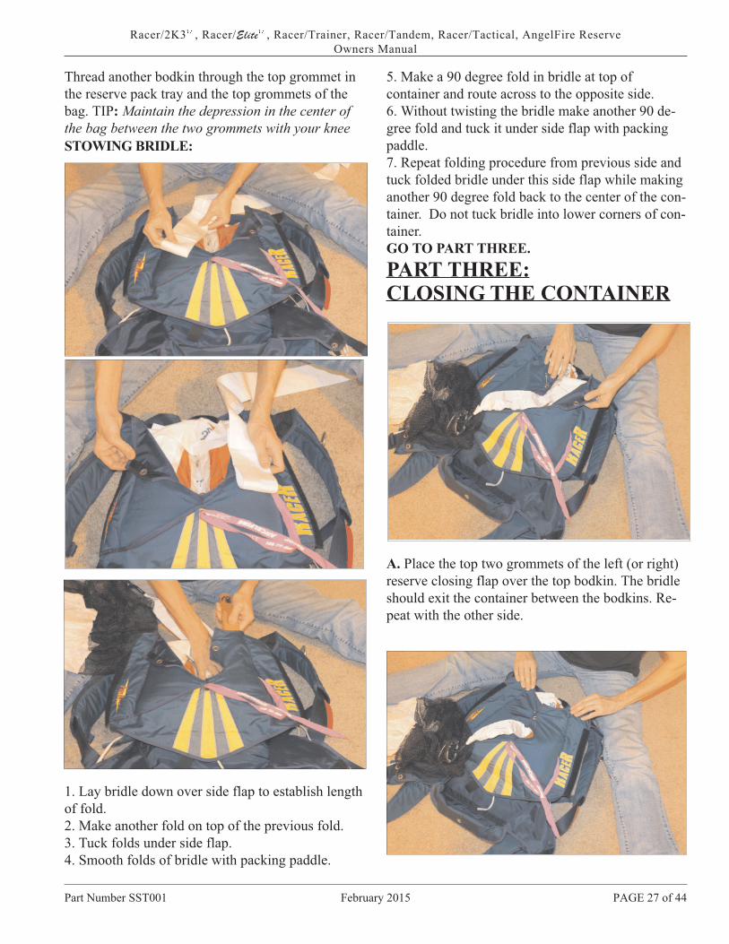
Thread another bodkin through the top grommet in
the reserve pack tray and the top grommets of the
bag. TIP: Maintain the depression in the center of
the bag between the two grommets with your knee
STOWING BRIDLE:
1. Lay bridle down over side flap to establish length
of fold.
2. Make another fold on top of the previous fold.
3. Tuck folds under side flap.
4. Smooth folds of bridle with packing paddle.
5. Make a 90 degree fold in bridle at top of
container and route across to the opposite side.
6. Without twisting the bridle make another 90 de-
gree fold and tuck it under side flap with packing
paddle.
7. Repeat folding procedure from previous side and
tuck folded bridle under this side flap while making
another 90 degree fold back to the center of the con-
tainer. Do not tuck bridle into lower corners of con-
tainer.
GO TO PART THREE.
PART THREE:CLOSING THE CONTAINER
A. Place the top two grommets of the left (or right)
reserve closing flap over the top bodkin. The bridle
should exit the container between the bodkins. Re-
peat with the other side.
Part Number SST001 February 2015 PAGE 27 of 44
Racer/2K3��
, Racer/Elite��
, Racer/Trainer, Racer/Tandem, Racer/Tactical, AngelFire Reserve
Owners Manual

B . Thread the bod kin through the top clos ing flap.
C. Lengthen the Quick Loop on the pi lot chute atleast four inches on the bot tom and three inches onthe top (more or less de pend ing on thick ness of con -tainer). Thread a pull- up cord through each loop.D. Tuck the re main ing six inches of re serve pi lotchute bri dle into the de pres sion formed be tween thetwo bodkins. Com press the pack job one more time, main tain ing the di vi sion of the “ears” of the can opy.
E. Set the pi lot chute on the folded bri dle.F. Thread the pull- up cords through the bodkins.
G. Com press the pi lot chute to the con tainer. Hold -ing it com pressed, flip the rig over onto its back.
Part Num ber SST001 Feb ru ary 2015 Page 28 of 47.
Racer/2K3 , Racer/Elite , SST/Trainer, Racer/Tan dem, Racer/Tac ti cal, An gel Fire ReserveOwn ers Man ual
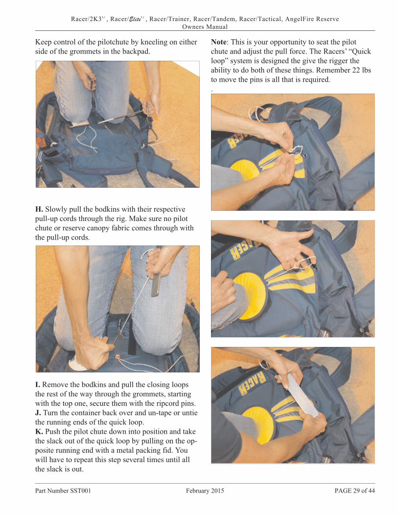
Keep control of the pilotchute by kneeling on either
side of the grommets in the backpad.
H. Slowly pull the bodkins with their respective
pull-up cords through the rig. Make sure no pilot
chute or reserve canopy fabric comes through with
the pull-up cords.
I. Remove the bodkins and pull the closing loops
the rest of the way through the grommets, starting
with the top one, secure them with the ripcord pins.
J. Turn the container back over and un-tape or untie
the running ends of the quick loop.
K. Push the pilot chute down into position and take
the slack out of the quick loop by pulling on the op-
posite running end with a metal packing fid. You
will have to repeat this step several times until all
the slack is out.
Note: This is your opportunity to seat the pilot
chute and adjust the pull force. The Racers’ “Quick
loop” system is designed the give the rigger the
ability to do both of these things. Remember 22 lbs
to move the pins is all that is required.
.
Part Number SST001 February 2015 PAGE 29 of 44
Racer/2K3��
, Racer/Elite��
, Racer/Trainer, Racer/Tandem, Racer/Tactical, AngelFire Reserve
Owners Manual

The best way to shorten the lower loop is to
pull on the running end of the Quick Loop
while standing and squeezing the pilotchute be-
tween your legs.
DRESSING THE CONTAINERA. Use the metal packing fid to tuck the Type 4
(square weave) valance under the pilotchute hat.
B. Using hemostats or tweezers grip the running
end of the Quick Loop about 1/4 inch back from
edge of hat and push slack through hole in hat val-
ance into area between top of pilot chute and bot-
tom of hat.
C. Tuck all but 1/16” into area below hat so that it
can be easily retrieved at the next inspection.
D. Insert packing paddle into opening provided in
the bottom corner of the container and run it along
the vertical partition shaping and smoothing as you
go.
E. Remove any slack in the reserve risers by pulling
on the Type IIa pullup cords. Then remove the pull-
up cords.
F. Using the packing fid, tuck in the bottom corners
of the vertical partition. Use this opportunity to
shape the sides of the container.
Part Number SST001 February 2015 Page30 of 44.
Racer/2K3��
, Racer/Elite��
, SST/Trainer, Racer/Tandem, Racer/Tactical, AngelFire Reserve
Owners Manual

G. Form the edges of the container so that the
pilotchute is effectively sitting in a concave
depression.
Seal the container, fill out the data card, and log.
COUNT YOUR TOOLS!
Part Number SST001 February 2015 PAGE 31 of 44
Racer/2K3��
, Racer/Elite��
, Racer/Trainer, Racer/Tandem, Racer/Tactical, AngelFire Reserve
Owners Manual

Racer 2K3
The flap closing sequence of the Racer 2K3 is:
1) bottom, 2) top, 3) side (either), 4) side.
Your Racer 2K3 can be configured for Pull-out or
Throw-out pilotchute or BOTH!
Classic Racer or Racer Elite
The flap closing sequence of the Classic Racer or
Racer Elite is 1) bottom, 2) side (either), 3) side,
4) top.
Your Classic Racer can be configured for Pull-out
or Throw-out pilotchute or BOTH!
Part Number SST001 February 2015 Page32 of 44.
Racer/2K3��
, Racer/Elite��
, SST/Trainer, Racer/Tandem, Racer/Tactical, AngelFire Reserve
Owners Manual
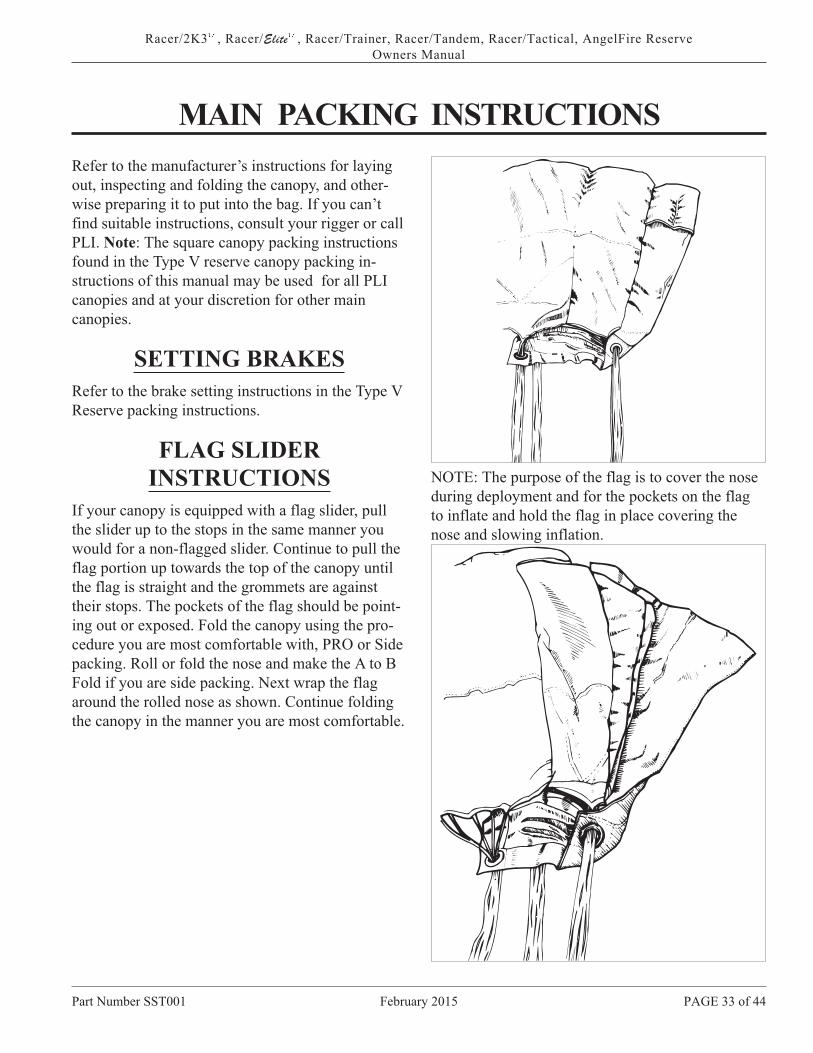
MAIN PACKING INSTRUCTIONS
Refer to the manufacturer’s instructions for laying
out, inspecting and folding the canopy, and other-
wise preparing it to put into the bag. If you can’t
find suitable instructions, consult your rigger or call
PLI. Note: The square canopy packing instructions
found in the Type V reserve canopy packing in-
structions of this manual may be used for all PLI
canopies and at your discretion for other main
canopies.
SETTING BRAKES
Refer to the brake setting instructions in the Type V
Reserve packing instructions.
FLAG SLIDER
INSTRUCTIONS
If your canopy is equipped with a flag slider, pull
the slider up to the stops in the same manner you
would for a non-flagged slider. Continue to pull the
flag portion up towards the top of the canopy until
the flag is straight and the grommets are against
their stops. The pockets of the flag should be point-
ing out or exposed. Fold the canopy using the pro-
cedure you are most comfortable with, PRO or Side
packing. Roll or fold the nose and make the A to B
Fold if you are side packing. Next wrap the flag
around the rolled nose as shown. Continue folding
the canopy in the manner you are most comfortable.
NOTE: The purpose of the flag is to cover the nose
during deployment and for the pockets on the flag
to inflate and hold the flag in place covering the
nose and slowing inflation.
Part Number SST001 February 2015 PAGE 33 of 44
Racer/2K3��
, Racer/Elite��
, Racer/Trainer, Racer/Tandem, Racer/Tactical, AngelFire Reserve
Owners Manual

SETTING BRAKES USING INTERMEDIARY LOOP
TM TMRacer/2K3 , Racer/Elite , Racer/Trainer, Racer/Tandem, Racer/Tactical, AngelFire Reserve
Owners Manual
The purpose of an intermediary loop on a riser is to reduce the amount of load on the brake eye and the toggle, when suspending heavy loads.
To set the brake, place the intermediary loop below the guide ring and pull the brake eye below the guide ring.
Put the intermediary loop through the brake eye.
Loop the folded end of the brake line sideways around the toggle.
Insert the nose of the toggle through the intermediary loop.
The excess brake line is routed either through the loop formed at the top of the riser or the Type 3 Tape loop provided on the front of the rear riser. If soft links are present do not route through the riser. Use the Type 3 Tape loop.
Insert the nose of the toggle into its keeper.
Part Number SST001 February 2015 Supplementary Page

6. The bridle can be routed out from under the right
or left side flaps..
7. Mate the small velcro strips on the pilot chute
bridle just above the curved pin. FAILURE TO
MATE THE VELCRO STRIPS CAN RESULT IN
A PILOT-CHUTE-IN-TOW MALFUNCTION.
Remove the Pull-up cord. FAILURE TO RE-
MOVE THE PULL-UP-CORD WILL PREVENT
THE CONTAINER FROM OPENING AND RE-
SULT IN A PILOT-CHUTE-IN-TOW MALFUNC-
TION.
FOLDING THE THROW-OUT PILOT CHUTE
A. Remove any twists from the bridle. Lay the pilot
chute mesh-side-up and S-fold the bridle radially
over the half of the pilot chute closest to the bridle’s
entry.
B. S-Fold the bridle radially over the half of the pi-
lot chute closest to the bridle’s entry.
C. Fold the pilot chute in half over the bridle.
D. Take the corners of the semi-circle and fold one
over the other into thirds.
E. Fold the pie-shape into thirds again.
F. Fold the new thin pie shape in half to make it
even thinner. Insert the pilotchute intothe pouch
with only the handle sticking out.
G.. Tuck remaining bridle under the bridle protector
flap and side flap.
Note: See Tandem Drogue & Bridle section for tips
on cocking Pull Out & Throw Out Pilot Chutes.
G. Flatten out the bundle, and make sure nothing
but the handle of the pilot chute sticks out of the
pouch.
H. For 2K3, tuck the “Walrus Teeth” on the main pin
protector flap under side and top flaps.
PAGE 35 of February 2015 Part Number Racer001
Racer 2K3�, Racer/Elite�, Racer/TRAINER, Racer/Tandem, Racer/Delta, PLI Reserve Canopies
Owners Manuak

FOR PULL-OUTA. Insert pull-up cord through closing loop. Pull
closing loop through bottom flap grommet and pin .
B. Insert the pull-out handle in its keepers or under
bridle protector flap mated to Velcro (in the case of
alternate pillow style handle).
C. Route bridle and base of pilotchute under right
side flap. Close right side flap followed by left side
flap and pin again.
S-fold the pilot chute bridle across the top of the
container, and lay (stuff), the pilot chute in the top
center of the bag (THE DEPRESSION CREATED
BY THE CLOSING LOOP MAKES AN EXCEL-
LENT RECESS FOR STOWING THE PILOT
CHUTE) with the base coming out of the right-hand
bottom corner.
E. Close top flap.
F. Insert the closing pin on the lanyardthrough the
closing loop so that it is oriented straight up and
down.
G. Check to see that the velcro on the lanyard is
mated to the velcro on the pilot chute retainer. This
is to assure enough slack movement of the lanyard
to be able to pull the pin without moving the pilot
chute.
H. Stow any excess lanyard under the right side
flap.
Part Number Racer001 February 2015 PAGE 36 of
Racer 2K3�, Racer/Elite�, Racer/TRAINER, Racer/Tandem, Racer/Delta, PLI Reserve Canopies
Owners Manual
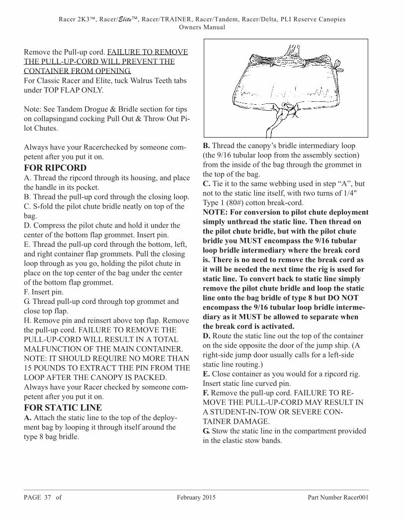
Remove the Pull-up cord. FAILURE TO REMOVE
THE PULL-UP-CORD WILL PREVENT THE
CONTAINER FROM OPENING.
For Classic Racer and Elite, tuck Walrus Teeth tabs
under TOP FLAP ONLY.
Note: See Tandem Drogue & Bridle section for tips
on collapsingand cocking Pull Out & Throw Out Pi-
lot Chutes.
Always have your Racerchecked by someone com-
petent after you put it on.
FOR RIPCORDA. Thread the ripcord through its housing, and place
the handle in its pocket.
B. Thread the pull-up cord through the closing loop.
C. S-fold the pilot chute bridle neatly on top of the
bag.
D. Compress the pilot chute and hold it under the
center of the bottom flap grommet. Insert pin.
E. Thread the pull-up cord through the bottom, left,
and right container flap grommets. Pull the closing
loop through as you go, holding the pilot chute in
place on the top center of the bag under the center
of the bottom flap grommet.
F. Insert pin.
G. Thread pull-up cord through top grommet and
close top flap.
H. Remove pin and reinsert above top flap. Remove
the pull-up cord. FAILURE TO REMOVE THE
PULL-UP-CORD WILL RESULT IN A TOTAL
MALFUNCTION OF THE MAIN CONTAINER.
NOTE: IT SHOULD REQUIRE NO MORE THAN
15 POUNDS TO EXTRACT THE PIN FROM THE
LOOP AFTER THE CANOPY IS PACKED.
Always have your Racer checked by someone com-
petent after you put it on.
FOR STATIC LINEA. Attach the static line to the top of the deploy-
ment bag by looping it through itself around the
type 8 bag bridle.
B. Thread the canopy’s bridle intermediary loop
(the 9/16 tubular loop from the assembly section)
from the inside of the bag through the grommet in
the top of the bag.
C. Tie it to the same webbing used in step “A”, but
not to the static line itself, with two turns of 1/4"
Type 1 (80#) cotton break-cord.
NOTE: For conversion to pilot chute deployment
simply unthread the static line. Then thread on
the pilot chute bridle, but with the pilot chute
bridle you MUST encompass the 9/16 tubular
loop bridle intermediary where the break cord
is. There is no need to remove the break cord as
it will be needed the next time the rig is used for
static line. To convert back to static line simply
remove the pilot chute bridle and loop the static
line onto the bag bridle of type 8 but DO NOT
encompass the 9/16 tubular loop bridle interme-
diary as it MUST be allowed to separate when
the break cord is activated.
D. Route the static line out the top of the container
on the side opposite the door of the jump ship. (A
right-side jump door usually calls for a left-side
static line routing.)
E. Close container as you would for a ripcord rig.
Insert static line curved pin.
F. Remove the pull-up cord. FAILURE TO RE-
MOVE THE PULL-UP-CORD MAY RESULT IN
A STUDENT-IN-TOW OR SEVERE CON-
TAINER DAMAGE.
G. Stow the static line in the compartment provided
in the elastic stow bands.
PAGE 37 of February 2015 Part Number Racer001
Racer 2K3�, Racer/Elite�, Racer/TRAINER, Racer/Tandem, Racer/Delta, PLI Reserve Canopies
Owners Manual

PLACING CANOPY INTO
BAG
1. Dress the canopy slightly wider than the bag.
2. Stack the canopy into a bundle the height and
width of the bag, and insert it into the bag. MAKE
SURE TO FILL THE CORNERS.
3. Thread one of the two center locking elastic stow
bands through its mating slot. Take a bight of can-
opy lines 25% of the bag width long, and wrap the
stow band around it. Repeat with the other center
locking stow.
4. Pull the pilot chute bridle or kill line of the col-
lapsible pilotchute out of the top of the bag until the
load-bearing ring on the top of the canopy seats
against the grommet on the top of the bag. Clear out
any extra fabric with your finger.
5. Stow the rest of the lines in bights 25% the width
of the bag long into the stow bands on the bottom
flap of the bag. Leave 8" to 15" of lines unstowed.
PLACING BAG INTO
CONTAINER
1. Set the bag in the tray of the container with the
lines facing toward the bottom of the rig.
2. Tuck the bights of the line stows under the box-
ing of each corner of the main container.
The flap closing sequence for the Racer 2K3 is:
1) bottom, 2) top, 3) side, (either) 4) side
The flap closing sequence for the Classic Racer or
Racer Elite is: 1) bottom, 2) side, (either) 3) side,
top.
FOR THROW-OUT3. Thread the pull-up cord through the closing loop.
4. Close the bottom flap to the closing loop, thread
the pull-up cord through the top flap and pull it
closed to the bottom flap.
5. Next thread the pull-up cord through the side flap
grommets and pull the closing loop through them
and pin the loop. .
Part Number Racer001 February 2015 PAGE 34 of
Racer 2K3�, Racer/Elite�, Racer/TRAINER, Racer/Tandem, Racer/Delta, PLI Reserve Canopies
Owners Manual

NOTE: The first stow in the rubber band of the
static line should be doubled or tripled to pre-
vent the prop blast from prematurely blowing
the pin out and allowing an open container.
DRESSING THE CONTAINER
A. After closing the top flap the rig is set up on its
side. With your thumb hold the main risers against
the bottom side of the over the shoulder part of the
harness. Place the risers in the riser covers and mate
the magnets. For the Elite, route the risers over the
outside edge of the shoulder and begin closing the
riser cover at the mid-flap working your way to the
top of the shoulder.
B. Pull the side (Epaulet) flap over the top of the
riser cover and mate the magnets.
Part Number Racer001 February 2015 PAGE 38 of
Racer 2K3�, Racer/Elite�, Racer/TRAINER, Racer/Tandem, Racer/Delta, PLI Reserve Canopies
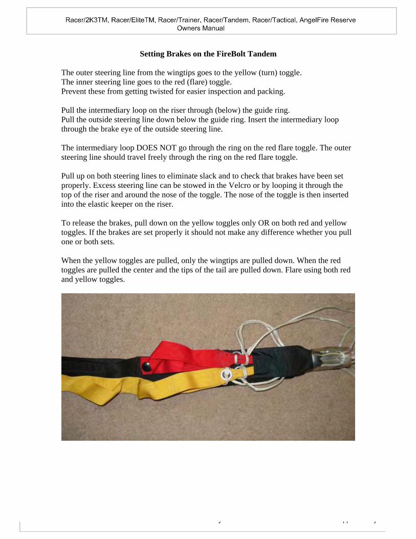
Setting Brakes on the FireBolt Tandem
The outer steering line from the wingtips goes to the yellow (turn) toggle. The inner steering line goes to the red (flare) toggle. Prevent these from getting twisted for easier inspection and packing. Pull the intermediary loop on the riser through (below) the guide ring. Pull the outside steering line down below the guide ring. Insert the intermediary loop through the brake eye of the outside steering line. The intermediary loop DOES NOT go through the ring on the red flare toggle. The outer steering line should travel freely through the ring on the red flare toggle. Pull up on both steering lines to eliminate slack and to check that brakes have been set properly. Excess steering line can be stowed in the Velcro or by looping it through the top of the riser and around the nose of the toggle. The nose of the toggle is then inserted into the elastic keeper on the riser. To release the brakes, pull down on the yellow toggles only OR on both red and yellow toggles. If the brakes are set properly it should not make any difference whether you pull one or both sets. When the yellow toggles are pulled, only the wingtips are pulled down. When the red toggles are pulled the center and the tips of the tail are pulled down. Flare using both red and yellow toggles.

Tandem Drogue & Main Container Closing
Cock the drogue/main pilotchute if your system is
so equipped. Pull the excess “kill line” up into the
canopy. “S” fold the main canopy into the main de-
ployment bag and insert the deployment bag into
the main container as described and shown in the
Main Packing Instructions.
Closing The Main Container
It is important to position the bag squarely into the
container, filling out the bottom corners of the con-
tainer tray. This will prevent the bag from “floating”
out of the tray in the event of a premature main con-
tainer opening.
Note: The main container bottom flap is fitted with
two closing grommets. The one located closest to
the outside edge is assembled into a triangular
shaped addition to the standard bottom closing flap.
This grommet is used for the first level closing as
follows.
First Level Closing
Insert your pull-up cord through the “Thru Loop”
located in the tray of the container.
Bring the pull-up cord up and over the top of the
main bag and through the grommet located in the
top main flap.
Part Number SST001 February 2015 PAGE 39 of 44
Racer/2K3��
, Racer/Elite��
, Racer/Trainer, Racer/Tandem, Racer/Tactical, AngelFire Reserve
Owners Manual
Tandem Drogue & Main Container Closing
Cock the drogue/main pilotchute if your system is
so equipped. Pull the excess “kill line” up into the
canopy. “S” fold the main canopy into the main de-
ployment bag and insert the deployment bag into
the main container as described and shown in the
Main Packing Instructions.
Closing The Main Container
It is important to position the bag squarely into the
container, filling out the bottom corners of the con-
tainer tray. This will prevent the bag from “floating”
out of the tray in the event of a premature main con-
tainer opening.
Note: The main container bottom flap is fitted with
two closing grommets. The one located closest to
the outside edge is assembled into a triangular
shaped addition to the standard bottom closing flap.
This grommet is used for the first level closing as
follows.
First Level Closing
Insert your pull-up cord through the “Thru Loop”
located in the tray of the container.
Bring the pull-up cord up and over the top of the
main bag and through the grommet located in the
top main flap.

Route the pull up cord through the first grommet in
the bottom main flap and close that flap to the top
flap.
Close the side flaps over this same grommet.
Pin the closing loop with the flexible pin on the
bridle. Mate the Velcro on the bridle to ensure
proper pin movement during pin extraction and
stow under the side flap.
Bridle Release Assembly
Note: There are three grommets on the bridle re-
tainer support harness, or drogue riser. The top
grommet accommodates the THIRD drogue release
mechanism. The small ring with the attached loop
threads through this top grommet, and is retained by
the third cable of the cutaway handle. The small
ring should be pre-assembled to the bridle retainer
harness.
With the large ring facing the reserve container, and
the bridle portion facing the main container, begin
to assemble the 3-Ring drogue release. Insert the
middle-size ring through the large ring, again facing
the reserve container. Insert the small ring through
the middle ring and fold it into position to receive
the closing loop.
The double-ended loop should be pre-assembled to
one of the two remaining drogue release cables (ei-
ther the primary OR the secondary release cable).
One end of the double-ended loop is inserted
through one of the two open grommets on the bridle
retainer harness or drogue riser.
Route the double-ended loop over or through the
small ring, depending on which end you are starting
from, and through the remaining grommet where it
is pinned with the last drogue release cable. Each
cable should go through ONE loop of the 3-Ring re-
lease system, then all three cables can be routed
through the Guide Loop at the top of the drogue
riser. The Guide Loop is not a functional part of the
drogue release sytem.
The drogue release cable ends should be inserted
into the channel of the bridle, above the large ring.
Part Number SST001 February 2015 Page40 of 44.
Racer/2K3��
, Racer/Elite��
, SST/Trainer, Racer/Tandem, Racer/Tactical, AngelFire Reserve
Owners Manual

Part of the excess bridle length, between the first
main pin and to a point about eight inches from the
base of the large ring, must be stowed in the hesita-
tor loop rubber band provided on the top main sub-
flap. Double the rubber band over this portion of the
bridle. Some slack (about eight inches) must exist
between the base of the 3-Ring system and the “S”
folded portion of the bridle, to allow the bridle to
“sit up” out of the container during drogue fall. This
step is critical to prevent accidental activation of the
main pin during droguefall.
.
Push entire assembly down toward the backpad as
far as it will go comfortably. “S” fold the remaining
bridle from side to side on top of the compartment
that you have just pushed the 3-Ring assembly into.
Leave the second (curved) pin out, to lock the mid-
flap.
Second Level Closing
Close the midflap as you would a standard Racer
with throw-out pilotchute, and pin it with the curved
pin.
Tuck the bridle under the right side flap edge and to
the pouch provided.
Part Number SST001 February 2015 PAGE 41 of 44
Racer/2K3��
, Racer/Elite��
, Racer/Trainer, Racer/Tandem, Racer/Tactical, AngelFire Reserve
Owners Manual

Double check the drogue centerline to verify it has
been “cocked,” if so equipped. The apex of the pi-
lotchute should be about even with the skirt when
cocked.
The easiest way to cock the PLI collapsible
pull out or throw out pilotchute
Attaching the PC/bridle/bag to the canopy:
1. Collapse the PC. Route the kill line through the
attachment ring or loop on the top of the canopy.
Open the “noose” formed in the end of the kill line
by the long finger trap, and thread the PC/bridle/bag
through it. Close the noose, and draw it up tight
against the ring/loop.
2. Route the limiting line through the ring/loop in
the same manner, passing the PC/bridle/bag through
it’s loop, and tighten it against the ring/loop.
Do not attempt to put both the kill line and limiting
onto the ring/loop simultaneously, or to put the lim-
iting line on first. This can result in the kill line cut-
ting through the limiting line.
Packing:
1. Leave the PC collapsed. Remove any twists be-
tween the bag and the canopy. Stack the canopy in
the normal manner, and place it into the bag.
2. Pull the kill line out of the gap where the bridle is
sewn to the bag. Simultaneously, reach inside the
bag with the other hand, making sure the kill line is
pulled out all the way, and no canopy fabric is
caught between the attachment ring and the #0
grommet in the bag. Lay the limiting line in a loop
over the top of the canopy inside the bag.
3. Continue packing in the normal manner, closing
the bag with the locking stows, and stowing the rest
of the lines.
4. Place the bag into the container, then place a foot
on the bag, while grasping the hackey (or the top of
the PC in the case of a pull out) with one hand and
the bridle with the other. Pull on the hackey, draw-
ing the kill line into the bridle. The PC is now
cocked, and can be checked by giving it a sharp tug
through the air, watching it catch air.
5. Continue closing the rig in the normal manner.
For Tandem:
Proceed as above, except rather than cocking the
drogue by pulling on the handle on top, grasp the
kill line where it exits the top of the bridle, and pull
all excess kill line up and out of the bridle, and into
the drogue canopy. This excess kill line is there to
compensate for bridle stretch during drogue fall,
and must be pulled into the drogue, so that when the
drogue is deployed, it is free to be drawn into the
stretched portion of the bridle, between the drogue
and the large ring on the bridle.
Note: It is necessary to pull the excess “Kill Line”
up into the drogue canopy. This will prevent prema-
ture failure of the “Kill Line”
Part Number SST001 February 2015 Page42 of 44.
Racer/2K3��
, Racer/Elite��
, SST/Trainer, Racer/Tandem, Racer/Tactical, AngelFire Reserve
Owners Manual
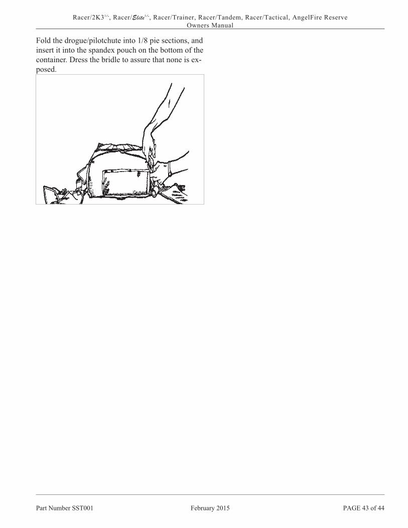
Fold the drogue/pilotchute into 1/8 pie sections, and
insert it into the spandex pouch on the bottom of the
container. Dress the bridle to assure that none is ex-
posed.
Part Number SST001 February 2015 PAGE 43 of 44
Racer/2K3��
, Racer/Elite��
, Racer/Trainer, Racer/Tandem, Racer/Tactical, AngelFire Reserve
Owners Manual

DONNING THE RACER
Before donning your Racer you should check the re-
serve ripcord pins, make sure that the seal is intact,
the pins are properly seated and there are no foreign
materials in the housing.
1. Grasp the Racer by the harness at one of the can-
opy release points, and put it on your back like a
coat. Check for twists in the main lift webs (front
straps) and leg straps.
2. Hook up the leg straps:
WITH THREAD THROUGH
LEG STRAPS
A. Check the leg strap for twists as you pass it un-
der your leg.
B. Bring it through the friction adapter from the side
against your leg and over the sliding bar.
C. Continue over the sliding bar and back through
the friction adapter.
MIS-THREADING THE LEG STRAP THROUGH
THE FRICTION ADAPTER MAY CAUSE YOU
TO FALL OUT THE BOTTOM OF THE HAR-
NESS.
D. Repeat with the other leg strap. Tighten the free
ends until snug, and stow them away.
WITH B-12 LEG STRAP
SNAPS
A. Check the leg strap for twists as you pass it un-
der your leg.
B. Snap the hook onto the V-ring. It should “clink”
when it closes the snap.
C. Repeat with the other leg strap. Tighten the free
ends until snug, and stow them away.
3. Locate the chest strap, and thread it like the leg
straps.
MIS-THREADING THE CHEST STRAP MIGHT
CAUSE YOU TO FALL FROM THE HARNESS.
Pull the free end until the main lift webs are paral-
lel. Place the free end in the elastic keeper.
Should your system be equipped with adjustable
horizontals, bend at waist, setting rig so it is com-
fortable on your back. Tighten horizontal free ends
at container base until it fits snugly. Stow free ends
under elastic keepers. Owners of pull-out systems
should take special note of proper stowing, as an
unstowed horizontal might be mistaken for a pull-
out handle. Repeat adjustment until comfortable fit
is obtained.
Part Number 001 February 2015 PAGE of
/Racer, Racer/Elite, /TRAINER
Owners Manual

FAMILIARIZATION
Now that you have learned how your rig works
(OPERATIONAL CHARACTERISTICS), the en-
vironment wherein it works best (OPERATIONAL
LIMITATIONS), how to assemble and pack it (AS-
SEMBLY, RESERVE PACKING INSTRUC-
TIONS, MAIN PACKING INSTRUCTIONS), and
how to put it on (DONNING THE ) it is time to
learn how to use it. This manual is not intended to
provide a curriculum on Skydiving, you MUST have
completed an approved (by your national Aero
club) course before you even think about taking to
the air by yourself. But now that your new rig is
packed and you have it on let’s get familiar with it.
There are three handles that you may have occasion
to pull. They are the main, the cut-away and the re-
serve. Let’s talk about the main first.
MAIN ACTIVATION
PULL-OUTTo learn about the activation of the pull-out, lay on
your chest in a skydiving arch, locate the pull-out
handle on the bottom right corner of the rig with
your right hand while your left hand compensates
for level fall. Don’t bother looking. You can’t see it
and you will need to be looking at traffic and alti-
tude while you are actually skydiving. Insert your
two center fingers between the two retainers of the
handle and remove the handle. While gripping the
handle thrust downward by extending your arm
straight down along the side of your body.
This action will open the pack and allow you to put
the pilot chute into the air stream to the right of
your head while you simultaneously look up over
your head to watch the deployment. KEEP YOUR
SHOULDERS LEVEL TO THE GROUND TO
PROVIDE FOR EVEN LINE DEPLOYMENT.
This procedure should be practiced on the ground
until you are comfortable and automatic with it. Ad-
ditionally, with a friend to hold the pull-out handle,
practice losing the handle and relocating it while
laying on your chest. Have the friend hold the han-
dle so as to simulate where it might be trailing be-
hind you out of its retainers. It could be anywhere
so have the friend move it through its complete
range of travel while you locate it. The procedure
for locating the handle is simple. With your left
hand on the reserve ripcord and your eyes on the
ground, reach behind you to the center of the main
container and trace the lanyard from the closing pin
to the handle, grip it and pull as described above.
THROW-OUTTo learn the use of a throw-out lay on your chest in
a skydiving arch with the rig on. Locate the plastic
cylindrical handle at the top of the right leg pad
with your right hand while your left hand compen-
sates for level fall. Don’t bother to look for the han-
dle. You probably can’t see it and you should be
looking at traffic and altitude in an actual skydive.
Grip the handle and extract the pilot chute from its
pouch and toss it vigorously into the air stream be-
side your body. Then look up over your head to
watch the deployment. As you look up your body
will come to vertical placing you in a sitting posi-
tion for the opening. You must not allow the pilot
chute to be released in front of your arm as that will
wrap the bridle around your arm. Make sure that the
pilot chute is released between your body and your
arm. To assure that this occurs release the pilot
chute before you look up. KEEP YOUR SHOUL-
DERS LEVEL TO THE GROUND TO PROVIDE
FOR EVEN LINE DEPLOYMENT.
PAGE of February 2015 Part Number 001
/Racer, Racer/Elite, /TRAINER
Owners Manual

RIPCORDLay on your chest on a flat surface and assume a
skydiving arch. Without breaking the arch look
down at the handle and insert the thumb of your
right hand into the loop of the handle while com-
pensating for level fall with your left hand. Thrust
your arm forward and down then look up over your
head to observe the deployment. Be sure to hold on
to the handle as they are expensive and could hurt
someone on the ground if you drop it.
CUTAWAY ACTIVATION
This familiarization should take place in a sus-
pended harness. Locate the red pillow type handle
on your right main lift web below your chest strap.
Peel the handle off the velcro and thrust the handle
down and away.
Students using the “ Stevens System” should keep
their head forward and down to prevent the cross
connector from hitting their head, additionally they
should select helmets that do not have a “snagable”
edge which might catch a suspension line, riser, or
cross connector.
You might want to locate and grip your reserve han-
dle before activating the cutaway but don’t take it
out of the pocket until your main has released.
Students should be additionally trained to release
both sides of the cross connector, from the main ris-
ers, upon confirmation of a fully inflated and func-
tioning canopy over their head. That canopy will
hopefully be the main. However, if an AAD misfire
occurred at precisely the wrong moment or the re-
serve were activated in any manner at that critical
time, it could be the reserve canopy. By deactivat-
ing the cross connector, the main, which would be
inflated and trailing behind the reserve, could be
cutaway safely. This deactivation procedure would
also prepare the main for cutaway, during ground
drag, after landing.
RESERVE ACTIVATION
In a skydiving arch, with your chest on a flat sur-
face locate the metal handle on your left main lift
web below the chest strap. Insert your left thumb
into the bottom curve of the handle while simulta-
neously gripping the vertical portion of the handle
with your right hand. With both hands thrust down
and away to the limit of your reach. You might want
to leave your elbows extended as much as possible
during the gripping phase, while looking up to keep
from going head down. Experienced jumpers can
bring their knees up for some additional compensa-
tion but newer jumpers must be cautious with this
maneuver, it can cause a back loop. Pulling the re-
serve ripcord should be additionally practiced while
in the suspended harness. A good time to practice
both the cutaway and reserve pull is at the end of
the certification cycle. The reserve must be in-
spected every 180 days, and that is a good time to
experience how much effort is required to operate
the handles of your Racer.
Part Number 001 February 2015 PAGE 46 of
Racer 2K3�, Racer/Elite�, Racer/TRAINER, Racer/Tandem, Racer/Delta, PLI Reserve Canopies
Owners Manual

Racer™ PERMANENT HISTORY RECORD
Container Serial # Date of Mfg. Rsv. Canopy Serial # Date of MFG.
Main Canopy Serial # Date of Mfg. Main Color Rsv. Color
This page provides for you a place to keep a permanent history record of your containerand canopies. You as the owner of this parachute system should provide this manual toyour rigger at the inspection/repack interval and they should fill out this page in addition tothe Packing Data Card in order to maintain a permanent history record of your system. Ifyour Packing Data Card is ever lost this page will act as a backup document.
Repair Record and Misc. Data
Inspection and Repack Record
Date Location Rigger Certificate No. Remarks