ra architecture
TRANSCRIPT

. . . . . . . . .
. . . . . . . . . . . . . . . . . . . . . . . . . . . .
2900 Bristol Street, Suite E-205 Costa Mesa, CA 92626-7909 Tel: 714.435.0380 Fax: 714.435.0383
Cogito Ergo Design TM
R2A Architecture
ADDENDUM - D October 26, 2010 To Project Bidding Documents For: Fullerton College Tech & Engineering La Habra Swing Space D.S.A. Appl. No. 04-111084 1000 South Leslie Drive D.S.A. File No. 30-C1 La Habra, CA 90631 (North Orange County Community College District) R2A Proj. No. 7018.10 R2A Architecture 2900 Bristol Street, Suite E-205 Costa Mesa, CA 92626-7909 Ph.: 714.435.0380 Fax.: 714.435.0383 TO PROSPECTIVE BIDDERS: This Addendum forms a part of the Contract Documents and modifies the original Bidding Documents as approved by DSA on September 15, 2010. Acknowledge receipt of this Addendum on the Bid Form. Failure to acknowledge may subject Bidder to disqualification. ATTACHMENTS: The following documents are a part of Addendum D: Specifications: Table of Contents
16710 – Telecommunications General Requirements 16715 - Telecommunications Acceptance Testing 16720 – Telecommunications Basic Materials 16721 – Air Blown Fiber 16725 – Telecommunications Cable 16760 – Telecommunications Grounding & Bonding


R2A Architecture Tech & Engineering – La Habra Site – Swing Space Costa Mesa, CA Fullerton College 09.09.10 North Orange County Community College District
TABLE OF CONTENTS
Introductory Documents
Title Page Seals Page Table of Contents Division 00000 General Conditions
Provided by Construction Manager in separate bound book.
Division 01000 General Requirements
01100 Summary 01250 Contract Modification Procedures 01290 Payment Procedures 01310 Project Management and Coordination 01320 Construction Progress Documentation 01322 Photographic Documentation 01330 Submittal Procedures 01400 Quality Requirements 01420 References 01500 Temporary Facilities and Controls 01524 Construction Waste Management 01570 Storm Water Pollution Prevention 01600 Product Requirements 01700 Execution Requirements 01731 Cutting and Patching 01732 Selective Demolition 01770 Closeout Procedures 01781 Project Record Documents 01782 Operation and Maintenance Data 01820 Demonstration and Training
Division 02000 Sitework
02221 Building Demolition 02230 Site Clearing 02300 Earthwork 02510 Asphaltic Concrete Paving 02660 Water Distribution System 02720 Storm Drainage Systems 02730 Sanitary Sewage Systems 02742 Pavement Marking 02751 Concrete Paving 02764 Pavement Joint Sealants 02821 Chain-Link Fences and Gates 02875 Post and Panel Signage
Division 03000 Concrete
Table of Contents 1

R2A Architecture Tech & Engineering – La Habra Site – Swing Space Costa Mesa, CA Fullerton College 09.09.10 North Orange County Community College District
03300 Cast-In-Place Concrete
Division 04000 Masonry
04810 Concrete Masonry Units Division 05000 Metals
05120 Structural Steel 05310 Steel Deck 05500 Metal Fabrications 05512 Prefabricated Metal Stairs 05521 Pipe and Tube Railings
Division 06000 Wood and Plastics
06100 Rough Carpentry 06160 Wood Sheathing 06185 Structural Glued-Laminated Timber 06421 Fiberglass Reinforced Panels
Division 07000 Thermal and Moisture Protection
07190 Water Repellents 07210 Building Insulation 07271 Building Underlayments 07552 SBS-Modified Bituminous Membrane Roofing 07620 Sheet Metal Flashing and Trim 07720 Roof Accessories 07841 Through-Penetration Firestop Systems 07920 Sealants
Division 08000 Doors and Windows
08110 Steel Doors and Frames 08311 Access Doors and Frames 08331 Overhead Coiling Doors 08710 Door Hardware 08800 Glazing
Division 09000 Finishes
09111 Non-Load-Bearing Steel Framing 09220 Exterior Plaster 09250 Gypsum Board 09512 Suspended Ceilings 09650 Resilient Flooring 09900 Painting
Division 10000 Specialties
10125 Bulletin Boards and Display Cases 10431 Signage
Table of Contents 2

R2A Architecture Tech & Engineering – La Habra Site – Swing Space Costa Mesa, CA Fullerton College 09.09.10 North Orange County Community College District
10521 Fire-Protection Specialties 10605 Wire Mesh Partitions 10801 Toilet and Bath Accessories
Division 11000 Equipment
11132 Projection Screens Division 12000 Furnishings 12355 Institutional Casework Division 13000 Special Construction (NOT USED) Division 14000 Conveying Systems (NOT USED) Division 15000 Mechanical Systems 15010 Basic Mechanical Requirements 15011 General Requirements for Equipment 15012 Equipment Control Devices 15015 Pipe Seals 15020 Mechanical Demolition 15053 Piping Tests 15060 Pipe and Pipe Fittings General 15061 Steel Pipe and Fittings 15062 Cast Iron Pipe and Fittings 15065 Ductile Iron Pipe and Fittings 15066 Copper Pipe and Fittings 15085 Piping Connections 15101 Gate Valves 15102 Ball Valves 15140 Supports and Anchors 15141 Seismic Restraints for Piping 15190 Mechanical Identification 15250 Insulation for Exposed Piping and Equipment 15290 Ductwork Insulation 15300 Fire Protection 15430 Plumbing Specialties 15440 Plumbing Fixtures 15450 Plumbing Equipment 15520 Refrigerant Specialties 15547 Pipe Cleaning 15860 Air Conditioning Units 15870 Fans 15886 Dust Collection System 15890 Ductwork 15910 Ductwork Accessories 15936 Air Inlets and Outlets 15950 Gas Fired Heaters 15990 Testing, Adjusting and Balancing Division 16000 Electrical Systems
Table of Contents 3

R2A Architecture Tech & Engineering – La Habra Site – Swing Space Costa Mesa, CA Fullerton College 09.09.10 North Orange County Community College District
Table of Contents 4
16010 General Electrical Requirements 16110 Raceways 16118 Underground Duct Banks 16120 Wire and Cable 16135 Boxes, Cabinets and Fittings 16140 Wiring Devices 16170 Grounding and Bonding 16190 Supporting Devices 16195 Electrical Identifications 16425 Switchboards 16440 Enclosed Switches 16461 Dry Type Transformers 16470 Panelboards 16475 Overcurrent Protective Devices 16510 Interior Lighting 16530 Exterior Lighting 16710 Telecommunications General Requirements 16715 Telecommunications Acceptance Testing 16720 Telecommunications Basic Materials 16721 Airblown Fiber 16723 Fire Alarm Requirements 16725 Telecommunications Cable 16760 Telecommunications Grounding & Bonding 16930 Low Voltage Remote Control Relay System
End of Table of Contents

R2A Architecture Tech & Engineering – La Habra Site – Swing Space Costa Mesa, CA Fullerton College 09.09.10 North Orange County Community College District
16710 - TELECOMMUNICATIONS GENERAL REQUIREMENTS
PART 1 - GENERAL
1.1 SECTION INCLUDES
A. Scope of Work
B. Other Affected Trades
C. Codes and Standards
D. General Requirements and Conditions
E. Telecommunication Contractor Qualifications
F. Qualifications of Subcontractors
G. Product Requirements
H. Submittals
I. Record Drawings
J. Definitions
1.2 RELATED SECTIONS
A. Contract Terms and Conditions
B. Section 16715 - Telecommunications - Acceptance Testing
C. Section 16720 - Telecommunications - Basic Materials and Methods D. Section 16721 – Telecommunication - Air Blown Fiber Basic Materials and Methods
E. Section 16725 - Telecommunications - Cable
F. Section 16760 - Telecommunications - Grounding and Bonding
1.3 SCOPE
A. Scope of Work
(1) The scope of work includes the provision, installation, testing, and documentation of physical resources for the Tech & Engineering-La Habra Site/Swing Space Telecommunications Infrastructure installation.
(2) The Contractor will provide all labor, materials, tools, equipment, and permits necessary for the satisfactory and timely completion of the project.
The Contractor and District’s representative shall jointly coordinate the implementation
Telecommunications General Requirements 16710-1

R2A Architecture Tech & Engineering – La Habra Site – Swing Space Costa Mesa, CA Fullerton College 09.09.10 North Orange County Community College District
of the project. To that end a pre-installation meeting(s) will occur between the various trade representatives and the District representatives (including Communication Services) prior to the installation of any facilities (equipment, copper cable termination blocks, voice/data/video systems, electrical service, HVAC ducts/units, etc.) in communication rooms or in building spaces.
B. Statement of Work
(1) The work includes, but is not limited to, the items outlined in the standards and indicated on the drawings, as well as all incidental items required to provide complete systems. The District, in agreement with the Contractor, will define the major portions of this work before construction is initiated.
(2) The scope of work includes the provision, installation, testing, and documentation of physical resources for voice, data and video systems required by the construction documents.
(3) The scope of work shall included the inter-building telecommunications pathways relocations, the installation of new manhole, pull boxes, fiber optic cables and copper cables as outlined in the contract drawings.
1.4 CODES AND STANDARDS; APPLICABLE PUBLICATIONS
A. All work shall be performed in compliance with the most restrictive of Municipal, State, and/or Federal Codes which may govern this work and shall conform to the following codes and standards:
(1) National Fire Protection Association
a. NFPA 70-National Electric Code with California Amendments ‘California Electrical Code
b. NFPA 101 - Life Safety Code
c. NFPA 258 - Standard Test Method for Measuring Smoke Generated by Solid Materials
(2) ANSI Standards
a. ANSI C2 National Electrical Safety Code
b. ANSI C80.3 Specification for Zinc-coated Electrical Metallic Tubing
c. ANSI/UL 797 Electrical Metallic Tubing
d. ANSI/ICEA S-83-596 - Fiber Optic Premises Distribution Cable Technical Requirements
(3) Electronics Industry Alliance/Telecommunications Industry Association (EIA/TIA)
a. EIA/TIA 568-B - Commercial Building Telecommunications Wiring Standard
b. EIA/TIA 569-B - Commercial Building Standard for Telecommunications Pathways and Spaces
c. EIA/TIA TSB 67 - Transmission Performance Standards for Field Testing of Unshielded Twisted-Pair Cabling Systems
d. EIA/TIA TSB 72 - Centralized Optical Fiber Cabling Guidelines
Telecommunications General Requirements 16710-2

R2A Architecture Tech & Engineering – La Habra Site – Swing Space Costa Mesa, CA Fullerton College 09.09.10 North Orange County Community College District
e. EIA/TIA TSB 75 - Additional Horizontal Cabling Practices for Open Offices
f. EIA/TIA 606-A - Administration Standard for the Telecommunications Infrastructure of Commercial Buildings
g. EIA/TIA 607-A - Commercial Building Grounding and Bonding Requirements for Telecommunications
h. EIA - 310-D - Cabinets, Racks, Panels, and Associated Equipment
i. EIA/TIA 526-14 - Optical Power Loss Measurements of Installed Multimode Fiber Cable Plant
j. EIA/TIA 455-57A - Optical Fiber End Preparation and Examination
k. EIA/TIA 455-59 - Measurement of Fiber Point Defects Using and OTDR
l. EIA/TIA 455-60 - Measurement of Fiber Cable Length Using an OTDR
m. EIA/TIA 455-61- Measurement of Fiber Cable Attenuation Using an OTDR
n. EIA/TIA 455-95 - Absolute Optical Power Test for Optical Fibers and Cables
o. EIA RS-458A Standard Optical Waveguide Fiber Material Classes and Preferred Sizes
p. EIA-472 Generic Specification for Optical Waveguide Fibers
q. EIA 232-C
(4) Federal Communications Commission (FCC) Part 15 and Part 68
(5) Title 24 - State of California Code of Regulations
(6) Uniform Building Code and UBC Standards and California Amendments (California Building Code, Part 2, Title 24)
(7) Occupational Safety and Health Act (OSHA) Standards
(8) City or County Electrical Code, as applicable
(9) IEEE Standards
a. IEEE 802.2
b. IEEE 802.3
(10) NEMA VE1 Cable Tray Systems
(11) Underwriters Laboratories Standards:
a. UL 497 Electrical Grounding and Bonding Equipment
b. UL 1479 Fire Tests of Through-Penetration Firestops
c. UL Building Materials Directory; Through-Penetration Firestops Systems, and Fill, Void or Cavity Materials
(12) The Uniform Mechanical Code
(13) ASTM Standards:
Telecommunications General Requirements 16710-3

R2A Architecture Tech & Engineering – La Habra Site – Swing Space Costa Mesa, CA Fullerton College 09.09.10 North Orange County Community College District
a. ASTM E 814 Methods of Fire Tests of Through-Penetration Fire Stops
b. ASTM E 136 Test Method for Behavior of Materials in a Vertical Tube Furnace at 750 degrees C
(14) Rural Electrification Association (REA), Bulletin 345-63, REA Standards for Acceptance Tests and Measurements of Telephone Plant
(15) Americans With Disabilities Act (ADA)
(16) CommScope, Inc. practices in accordance with SYSTIMAX SCS Design & Installation Guidelines.
(17) California State District, Office of the Chancellor - Telecommunications Infrastructure Planning (TIP) Standards – including the most recently issued TIP updates
(18) North Orange County Community College District TELECOMMUNICATION INFRASTRUCTURE STANDARDS.
B. Where reference is made to a requirement that exceeds minimum code requirements, the specification requirement shall take precedence. The Contractor and District representative shall jointly resolve any work that is in apparent conflict with applicable codes.
C. When these standards call for materials or construction of better quality or larger sizes than required by the above-mentioned rules and regulations, the provisions of these standards shall take precedence.
D. In accordance with these laws, rules, and regulations, the Contractor shall provide the following:
(1) Any additional material and labor that may be required for compliance with these laws, rules, and regulations, even though the work is not mentioned in these particular standards.
(2) All permits required by any of the legally constituted public authorities for the installation or construction of the work.
(3) Any inspection or examinations required. Copies of certificates of all such inspections shall be delivered to the District representative.
(4) If any work is concealed without proper inspection and approval, the Contractor shall be responsible for all work required to open and restore the concealed areas, in addition to all required modifications.
1.5 GENERAL REQUIREMENTS AND CONDITIONS
A. Safety and Indemnity
(1) The Contractor shall be solely and completely responsible for conditions of the job site, including safety of persons and property during performance of work.
(2) The Contractor shall ensure that all personnel working in or anywhere on the site shall be provided a hard hat, safety shoes, a face shield or safety goggles, etc. for their protection.
(3) If required by the campus, all personnel working in or anywhere on the site shall display
Telecommunications General Requirements 16710-4

R2A Architecture Tech & Engineering – La Habra Site – Swing Space Costa Mesa, CA Fullerton College 09.09.10 North Orange County Community College District
a photo-ID designed by the campus or an approved equivalent.
(4) The Contractor shall ensure that all personnel working in or anywhere on the site shall conform to the campus’s regulations regarding confined space.
(5) No act, service, drawing review, or construction observance by District representative or any other party employed by the campus is intended to include review or approval of adequacy of the Contractor’s safety measures, in, on, or near the construction site.
B. Quality Assurance
(1) The standards contained herein are set forth as the minimum acceptable requirements of the Contractor’s Quality Assurance program. The Contractor is responsible for executing any other Quality Assurance measures necessary to ensure complete and fully functioning systems within the scope of this project.
(2) The Contractor shall ensure that all design, workmanship, materials employed, required equipment, and the manner and method of installation conform to accepted practices. Where specific standards do not apply, the more stringent of industry publications, NOCCCD and campus policies and manufacturer’s guidelines.
(3) The Contractor shall also ensure that each piece of equipment is in satisfactory working condition.
(4) The Contractor shall certify that the cable manufacturers have carried out the quality assurance tests and procedures as specified herein. An ISO9001 Certified Manufacturer must manufacture all cable.
(5) The Contractor is responsible for ensuring that the cable packaging for shipping/storage purposes meets or exceeds the following requirements:
a. One continuous length of cable per shipping reel/container.
b. Reels must be wooden or steel, sturdy, lagged, and shall have thermal protection jackets applied prior to lagging.
c. Each reel/container shall be individually identified and marked with the length of the cable it contains. Said marking shall withstand weather and shipping conditions and remain readable.
d. For fiber optic cable, results of the 100% Attenuation Tests conducted at the factory shall accompany each reel.
e. Cable shall be packed in a manner that facilitates the pre-installation tests to be conducted while the cable is still on the reel (i.e., both ends of the cable must be accessible while protected from moisture).
f. The Quality Assurance Plan employed shall include on-reel testing of fiber and UTP, including, but not limited to, OTDR, power loss, attenuation, etc. (as applicable for given cable media).
C. Manufacturer’s Literature: Where these standards call for an installation to be made in accordance with the manufacturer's recommendations, a copy of such recommendations shall always be kept on the job site and shall be available to District representative.
D. Acceptance of Project
Telecommunications General Requirements 16710-5

R2A Architecture Tech & Engineering – La Habra Site – Swing Space Costa Mesa, CA Fullerton College 09.09.10 North Orange County Community College District
(1) NOCCCD and the Contractor shall accept the project as complete based on the following criteria:
a. Before executing any performance testing, the Contractor shall present a test plan to the District representative for their approval.
b. The Contractor has completed all testing and delivered copies of all test results to the District representative.
c. All test results have been examined and approved by the Contractor and District representative.
d. Copies of all documentation required by this section have been delivered to District representative.
e. All punch list items are completed to the satisfaction of the District representative.
f. SYSTIMAX Certification Certificates are provided by the Contractor to the District representative.
(2) Following completion and/or compliance with the requirements listed above, the Contractor shall issue a Notice of Completion confirming that the project is complete. A 45-day acceptance period shall begin immediately following the issuance of the Notice of Completion.
(3) Minor failures shall be responded to at the District discretion or within one business day.
E. Guarantee and Warranties
(1) The installed structured wiring system (including both inter- and intra-building subsystems utilizing copper and fiber optic cabling) shall be a Commscope, Inc. SYSTIMAX Structured Cabling System, certified for a 20-year period.
a. 20-Year Extended Product Warranty - The 20 Year Extended Product Warranty shall ensure against product defects, that all approved cabling components exceed the specifications of TIA/EIA 568-B and ISO/IEC IS 11801, exceed the attenuation and NEXT requirements of TIA/EIA TSB 67 and ISO/IEC IS 11801 for cabling links/channels, that the installation will exceed the loss and bandwidth requirements of TIA/EIA TSB 67 and ISO/IEC IS 11801 for fiber links/channels, for a twenty (20) year period. The warranty shall apply to all passive SCS components.
b. The 20-Year Extended Product Warranty shall cover the replacement or repair of defective product(s) and labor for the replacement or repair of such defective product(s) for a twenty (20) year period.
c. 20-Year Application Assurance - The 20-Year Application Assurance shall cover the failure of the wiring system to support the application which it was designed to support, as well as additional application(s) introduced in the future, up to 622Mbps parallel transmission schemes, by recognized standards or user forums that use the TIA/EIA 568-B or ISO/IEC IS 11801 component and link/channel specifications for cabling, for a twenty (20) year period.
(2) 20 year future-flex warranty on the air blown tube cable and fiber optic cables from Sumitomo. Warranty to include all materials and labor.
(3) Acceptable proposed Systems will be covered by a two-part certification program
Telecommunications General Requirements 16710-6

R2A Architecture Tech & Engineering – La Habra Site – Swing Space Costa Mesa, CA Fullerton College 09.09.10 North Orange County Community College District
provided by a single manufacturer and that manufacturer’s certified vendor. The first part is an assurance that the certified system will support the applications for which it is designed (including certified Category 6) during the lifetime of the certified system. The second portion of the certification is a twenty-year warranty provided by the manufacturer and the vendor on all products within the system (i.e., cords, telecommunications outlet/connectors, cables, cross-connects, and baluns). Manufacturer shall administer a follow up program through the vendor to provide support and service to the District.
(4) The Contractor shall be responsible for correcting any problems and malfunctions that are warranty-related for the entire warranty period.
(5) Copies of any extended material warranties shall be passed through to the District representative.
(6) During the installation and up to the date of final acceptance, the Contractor shall protect all finished and unfinished work against damage and loss. In the event of such damage or loss, the Contractor shall replace or repair such work at no cost to the District or any other Trade Partnership working on the project.
F. Schedule
(1) The Contractor shall submit, prior to project start, a time line for the project, showing all major dependencies and interactions with other trades. The schedule shall:
a. Identify any and all disruption to existing services and/or service shutdowns on the schedule.
b. Identify specifically the anticipated completion date for the project. These completion dates shall be designated as milestones on the schedule.
(2) The Contractor shall not take any facility out of service during the District normal hours of operation without agreement from the campus. Any out-of-service activity shall be requested in writing and be coordinated two weeks in advance. The activity should generally be scheduled after hours.
(3) The Contractor shall make updates to the time line and shall provide a weekly written status report to the District representative.
a. Each status report shall include details of project progress and shall describe any special incidents, activities, circumstances, or interruptions of workflow.
b. The status reports shall specifically itemize areas that shall be affected by project activities planned for the succeeding week.
1.6 TELECOMMUNICATIONS CONTRACTOR QUALIFICATIONS
Systimax Contractor Qualifications: (voice and data)
A. To ensure that the quality of the work performed meets the standards of the District and the standards that have been established since the earthquake, the following items identify requirements of the Contractor in order to bid this project.
(1) The Contractor must be a SYSTIMAX certified Business Partner in good standing with CommScope, Inc. within the geographical region in which the campus resides (Southern California).
Telecommunications General Requirements 16710-7

R2A Architecture Tech & Engineering – La Habra Site – Swing Space Costa Mesa, CA Fullerton College 09.09.10 North Orange County Community College District
B. To qualify for the bid, the District representative, its communications consultant, its construction management firm, and Commscope Inc. (only to appropriate systems) must evaluate the quality of work to ensure that our standards can be met.
C. The Contractor must hold a valid State of California Contractor’s license with the proper telecommunications classifications.
D. The Contractor must have a SYSTIMAX-certified installer/foreman on-site throughout the cabling project that holds a current SYSTIMAX Installation & Maintenance designation.
E. The Contractor must have a SYSTIMAX-certified person within its organization that holds a current SYSTIMAX Design & Engineering Designation.
F. The Contractor that installs the voice and data systems is the main telecommunications contractor and as such will oversee all aspects to the telecommunications project including voice, data, and video networks utilizing copper, fiber optics and coaxial cabling. If the main telecommunications contractor is not qualified to install the video system(s), then qualified subcontractors must be provided for that portion of the total telecommunications project. (See video contractor qualification below.)
Video Contractor Qualifications: Not applicable.
Broadband Communications Engineer: Not applicable.
Complete (RF) MATV System: Not applicable.
1.7 QUALIFICATIONS OF SUBCONTRACTORS
A. All subcontractors employed by the Contractor shall have a minimum of 5 years’ experience in satisfactory completion of jobs of similar scope and amount.
B. The Contractor shall compile detailed information relating to similar work involving Category 5e cabling and optical fiber completed by all subcontractors during the previous twelve months. This information shall include corporate references sufficient to enable the District representative to evaluate and agree to the subcontractors’ responsibility, experience, and capacity to perform the work.
C. Each subcontractor employed by the Contractor to perform telecommunications work on a NOCCCD project shall possess a C-7 (formerly C-61) Limited Specialty License for Telecommunications and must be certified by Commscope Inc., as a authorized SYSTIMAX Structured Cabling System Business Partner for the installation, termination, splicing, and testing of copper cables, fiber optic cable, riser cable, and inside wiring. The same regional certification statement for contractors applies to subcontractors. This requirement ensures integration into, support, maintenance, and warrantee by the Contractor of the District existing telecommunications infrastructure. The appropriate subcontractor’s license for underground construction and conduit installation is also required.
D. An on-site Contractor superintendent must be available at all times. District representatives must be able to contact said person either in person, by telephone, or by pager.
1.8 PRODUCT REQUIREMENTS
A. General Information
Telecommunications General Requirements 16710-8

R2A Architecture Tech & Engineering – La Habra Site – Swing Space Costa Mesa, CA Fullerton College 09.09.10 North Orange County Community College District
(1) This section identifies the minimum standards for product quality acceptable to NOCCCD by designating a manufacturer’s trade or brand name and catalog or model number and by describing attributes, performance, or other standards.
(2) Where applicable, Commscope, Inc. products are specified as the standard for quality and performance of products to be used in this installation.
(3) For products described only by attributes, performance, or standards, the Contractor shall develop a Product Submittal in accordance with the requirements set forth herein and review it with District representative.
(4) Such phrases as “or equal,” “or equivalent,” and “or acceptable substitute” indicate that an equivalent product may be proposed as a substitute for that which is specified. The proposed substitution must meet or exceed the attributes, performance, or other standards of the specified product and must be approved by District representative.
(5) Failure of the Contractor to submit proposed substitutions for approval in the manner described above shall be sufficient cause for disapproval by the District of any substitutions otherwise proposed.
(6) Physical samples may be required. If tests for the determination of equality and utility are required by the District, they shall be made by a testing laboratory, with the acceptance of the test procedure first given by District representative, at the expense of the Contractor.
B. Quality of Materials
(1) All materials and equipment supplied by the Contractor shall be new, manufactured within one (1) year prior to installation, and shall meet or exceed the latest published standards of the manufacturer. All material shall be acceptable to and approved by the District representatives as meeting these standards.
(2) All communications materials used on this project shall conform, where applicable, to the following standards, unless otherwise noted:
a. NEMA - National Electrical Manufacturers Association
b. ANSI - American National Standards Institute
c. UL - Underwriters Laboratories, Inc.
d. The latest IEEE and EIA/TIA 568 standards
e. FCC and NCTA Coaxial Cable Television Standards
(3) Communications systems materials and equipment shall be FCC Type-accepted and certified as such by supplier.
(4) No material employed shall present environmental or toxicological hazards as defined by current industry standards. All materials shall comply with CAL OSHA and EPA standards or applicable federal or state laws or regulations.
(5) The equipment, apparatus, and material for fiber optic equipment and apparatus shall conform to existing CAL OSHA health and safety laws. The equipment and apparatus shall have provision for application of safety labels such as LASER identification or warning labels as required by system considerations.
Telecommunications General Requirements 16710-9
R2A Architecture Tech & Engineering – La Habra Site – Swing Space Costa Mesa, CA Fullerton College 09.09.10 North Orange County Community College District
C. Materials Delivery and Storage
(1) Costs of all shipping to the site, inside handling, and all unusual storage requirements shall be borne by the Contractor.
(2) The Contractor shall make appropriate arrangements and coordinate with authorized personnel at the site for the proper acceptance, handling, protection, and storage of materials so delivered.
1.9 SUBMITTALS
A. Shop Drawings and Supplemental Data
(1) Copies of shop drawings and supplemental data shall normally be provided for the District review. Shop drawings shall be submitted for all communications equipment, cabling, and structure pertaining to the job (distribution frames, conduit, wire, fiber optic cable, optical terminations, splices, etc.).
(2) Design submittals (reflecting field conditions, actual cable lengths, equipment elevations, and performance expectations) shall be prepared for each system included in the project scope and reviewed with District representative.
(3) Copies of final shop drawings and supplemental data, where called for, shall be submitted to the District representative. Final corrected copies of schedules and shop drawings or supplemental data shall be as follows (exceptions shall be noted in Specification Sections):
a. One (1) for the Campus Master Plan Architect's files, if applicable
b. One (1) for the Telecommunications Master Plan Engineer's files, if applicable
c. Two (2) for the District (Facilities Planning and IS Network Administration)
d. One (1) for the Contractor’s job files, and such additional copies as the Contractor may desire for its own office files and/or for distribution to subcontractors or vendors.
(4) The shop drawings and supplemental data called for shall be submitted as the instruments of the Contractor, even though they may have been prepared by a subcontractor, supplier, dealer, manufacturer, or by any other person, firm, or organization. Prior to submission, the Contractor shall undertake its own review and stamp with its acceptance, then submit to District representative for their review.
By accepting and submitting shop drawings and supplemental data, the Contractor represents that the Contractor has determined and verified all field measurements, the physical construction, the quality of materials, the applicability of catalog numbers, and similar data, or will do so, and that the contractor has checked and coordinated each shop drawing with the requirements of the field conditions. Conflicts between trades shall be resolved by the Contractor in the shop drawings, if possible, but in any event prior to the actual construction.
(5) All shop drawings shall be drawn accurately on paper suitable for duplicate copying by black, blue line printing processes or Xerox.
(6) Supplemental data shall include information as noted in the specification paragraphs requiring them.
Telecommunications General Requirements 16710-10

R2A Architecture Tech & Engineering – La Habra Site – Swing Space Costa Mesa, CA Fullerton College 09.09.10 North Orange County Community College District
(7) District representative will review shop drawings and supplemental data submitted by the Contractor only for general design conformance with the concept of the project and compliance with the information given in the Contract Documents.
(8) Shop drawings, if requested shall be submitted to and favorably reviewed by District representative before being used by the Contractor on the job.
(9) Shop drawings delineation: The shop drawings shall be drawn to scale and shall be completely dimensioned, giving the plan together with such sections as are necessary to clearly show construction detail.
(10) Responsibility
(a) These shop drawings and all supporting data, catalogs, etc., shall be prepared by the Contractor or its suppliers, but shall be submitted as the instruments of the Contractor. Therefore, the Contractor shall check the drawings of its suppliers as well as its own drawings before submission.
(b) In particular, the Contractor shall ascertain that the drawings meet all requirements of the drawings and standards and also confirm to the structural and space conditions.
(c) Each shop drawing submitted for the District representative approval shall bear a stamp certifying that it has been checked by the Contractor in accordance with the standards. If such shop drawings show variations from Contract Documents, whether because of standard shop practice or other reasons, the Contractor shall make special mention thereof in the letter transmittal.
(d) The Contractor shall be fully responsible for observing the need for and making any changes in the arrangement of piping, connections, wiring, manor of installation etc. that may be required by the proposed equipment, both as pertains to its own work and any work affected under other parts, headings, or divisions of Drawings and Standards.
(11) Identification: Shop drawings shall be entitled with the name of the project on each sheet and shall otherwise be identified by listing the particular division, section, article or reference of the work to which they pertain. Different items shall be submitted on separate sheets, and all submittals shall be numbered serially.
(12) Manner: The Contractor shall furnish for District representative approval separate submittal sheets for each specialty item in the following manner:
(a) Catalog cuts shall be photocopied or reproduced in some other acceptable manner and submitted five (5) copies on one side only of an 8 1/2" x 11" sheet, noting only the items in question, together with the descriptive (specification) data. Drawings shall be submitted in ozalid transparency form.
(b) Each sheet shall be identified with the division, section, article or reference in the Contract Documents that covers the item submitted for approval.
(c) Each sheet shall be identified with the project name.
(d) Each sheet shall bear the Contractor's stamp and signature of approval.
1.10 RECORD DOCUMENTATION
A. The Contractor shall keep one set of drawings on site to continually maintain an accurate record of the as-constructed work.
Telecommunications General Requirements 16710-11

R2A Architecture Tech & Engineering – La Habra Site – Swing Space Costa Mesa, CA Fullerton College 09.09.10 North Orange County Community College District
B. All as-built documentation, including red-line as-builts of construction documents, shall be provided in AutoCad, Version 14 or greater.
C. The marked-up drawings shall accurately indicate location of equipment, pull-boxes, conduits, cable types and labeling.
D. All cabling placed must be entered into electronic database (Excel) approved by the District representative. The District representative shall provide the format and details to the Contractor, including cable number, count scheme, and terminal designations. The completed database file is to be presented to the District representative before the completion of the project in order for the District to establish assignment records.
E. Room schedule requirements shall be reflected on the Contract Documents.
F. Within 30 days of completing work, the Contractor shall submit five (5) copies of as-built drawings to the District representative. In addition, the Contractor shall provide an electronic copy of the as-built drawings in a format specified by the District.
1.11 DEFINITIONS
• Backboard: Backboard generally refers to the A-C, fire-retardant, plywood sheeting lining the walls of the telecommunications facilities. Backboards may also refer to the entire wall-mounted assembly, including wire management and termination frames.
• Building Distribution Frame (BDF): The BDF is the location within a building where the entire inside cable and fiber optic plant originates. The entire cable and fiber optic entrance facilities also terminate here. Part of the Horizontal Distribution System may originate here as well.
It may include: the physical location, enclosure, wire and copper cable management hardware, fiber and management hardware, termination hardware, distribution hardware, protection hardware, active electronic components, and equipment racks. EIA/TIA-569 “Commercial Building Standard for Telecommunications Pathways and Spaces” refers to the room housing the BDF as the Equipment Room. Throughout this specification, BDF and Telecommunications Equipment Room are equivalent.
• CATV: Cable Antenna Television system.
• Cable Plant: Cable, conduit raceways, vaults, junction/pull boxes, rooms, racks, equipment, patch bays/blocks, and other infrastructure required to provide physical, electrical, optical connectivity between buildings on the Campus.
• Cable Rack: Hardware designed and manufactured for horizontal pathway distribution of cable and inside wiring inside the MDF, BDF, or IDF rooms.
• Cable Tray: Hardware designed and manufactured for horizontal pathway distribution of cable and inside wire from the MDF, BDF, or IDF to the Information Outlet access point.
• Copper Entrance Cable: Copper Cable that joins the District backbone infrastructure at its connecting point to the buildings BDF.
• Designation Strips: Paper or plastic strips, usually contained in a clear or color tinted plastic carrier, designated for insertion into a termination frame. Designation strips are usually imprinted with the adjacent terminal number and are used to aid in locating a specific pair, group of pairs, or
Telecommunications General Requirements 16710-12

R2A Architecture Tech & Engineering – La Habra Site – Swing Space Costa Mesa, CA Fullerton College 09.09.10 North Orange County Community College District
information outlet inserted into the termination frame, or for the purpose of delineating a termination field.
• Entrance Conduit: Conduit that connects the District underground infrastructure with the building's BDF.
• Fiber Entrance Cable: Fiber Optic cable that joins the District backbone infrastructure at its connecting point to the building’s BDF.
• Information Outlet: An integral assembly containing one of the following: (a) Three, 4 pair Category 6 telephone jacks that can be used for various services (voice,
data, network, etc.); one is ivory, another is gray, and the third is orange.
(b) Two, 4 pair Category 6 telephone jacks (one ivory, one orange) and 1 fiber optic jack.
(c) Two, 4 pair Category 6 telephone jacks (one ivory, one orange) and 1 coaxial cable jack.
(d) One, 4 pair Category 6 telephone wall jack.
(e) All jacks shall be mounted in dual gang standard electrical outlet box. A mounting frame and blank dust cover(s) are provided for the unused position. The assembly includes the faceplate, modular mounting frame, jacks, and dust cover/blank. Dual gang outlet boxes will contain a second modular mounting frame equipped with dust cover/blanks instead of jacks and will be covered. Each colored jack will be served by a different colored cable.
• Inside Plant (ISP): Communications system inside a building (wire, cable equipment and racks, information outlets, etc.).
• Intermediate Distribution Frame (IDF): The IDF is the location in a building where a transition between the Riser System and the Horizontal Distribution System occurs. It may include: the physical location, enclosure, wire and cable management hardware, fiber and management hardware, active electronic components, termination hardware, and equipment racks. EIA/TIA-569, “Commercial Building Standards for Telecommunications Pathways and Spaces” refers to the IDF as the Telecommunications Closet. Throughout this specification IDF and Telecommunications Room are equivalent.
• LAN: Local Area Network.
• Commscope - SYSTIMAX - Structured Connectivity Solutions (SCS): SCS is a structured information system for copper, fiber optic and wireless solutions for inter and intra-building telecommunications by Commscope, Inc..
• Main Distribution Frame (MDF): The MDF is the facility where the entire outside cable and fiber optic plant originates. It may include the physical location, enclosure, wire, fiber and copper cable hardware, protection, active electronic components, equipment frames, and racks. The Telecommunications Switching Center and/or Computer Center may vary by campus.
• MPOE: Minimum Point of Entry, Utility Partnerships/Alternate Carrier, located within the MDF.
• Management Hardware (1) Fiber Management: Hardware designed and manufactured for the purpose of keeping
fiber patch cords neat and orderly. Most termination frame manufacturers provide fiber
Telecommunications General Requirements 16710-13

R2A Architecture Tech & Engineering – La Habra Site – Swing Space Costa Mesa, CA Fullerton College 09.09.10 North Orange County Community College District
management components designed to work in conjunction with their termination frames. Fiber management may also refer to other types of hardware for the purpose of securing fiber optic cable to the building.
(2) Wire Management (Copper, Data, Network): Hardware designed and manufactured for the purpose of keeping cross-connect wire and patch cables neat and orderly. Most termination frame manufacturers provide wire management components designed to work in conjunction with their termination frames. Wire management may also refer to other types of hardware for the purpose of securing wire and cable to the building.
• Outside Plant (OSP): Communications system outside of the buildings (typically underground conduit and vaults, exterior/underground rated wire and cable, etc.).
• Riser Cable: High volume cable (copper) that connects the BDF with the IDF or backboards located on the same or different floors.
• Riser Conduit: Conduit that connects the BDF to the IDF or backboards located on the same or different floors.
• Riser Fiber Cable: Fiber Optic Cables that connects the BDF with IDF or backboards located on the same or different floors.
• SPOE: Secondary Point of Entry, Utility/Alternate Carrier Partnership in buildings other than the MDF.
• Station Wire: Three (different colored) - 4 pair, unshielded, twisted pair, Category 6 wire that connects the information outlet to the BDF or IDF.
• Telecommunications Ground: An electrical ground (as defined by local codes) usually the main building ground electrode extended by a continuous AWG “0” wire to ground bus bars in the BDF, IDF, and roof telecommunications terminal point.
• Termination Fields (1) Copper, Data, Network Termination Fields: A group of termination frames clustered
together to provide terminations for specific cable or inside wiring groups, where all of the cable or wiring in the group is used for a single purpose, constitutes a copper, data, or network termination field. The extent of a specific field, located in a group of fields, may be distinguished by a physical separation between the frames forming the field, by uniquely colored designation strips, or by a series of terminal numbers.
(2) Fiber Optic Termination Fields: A group of termination frames clustered together to provide terminations for fiber optic cable fibers, where all of the cable fibers are used for a single purpose, constitutes a fiber termination field.
Telecommunications General Requirements 16710-14

R2A Architecture Tech & Engineering – La Habra Site – Swing Space Costa Mesa, CA Fullerton College 09.09.10 North Orange County Community College District
Telecommunications General Requirements 16710-15
• Termination Frames (1) Copper Termination Frames: Devices designed and manufactured for the purpose of
terminating large numbers of copper cable or station wire pairs. These devices generally utilize insulation displacement connections and usually require special tools to make the terminations. Throughout this specification, the terms Copper Termination Frame and Wiring Block are equivalent.
(2) Data Termination Frame: Devices designed and manufactured for the purpose of terminating copper cable pairs from the active data electronic hardware. These devices generally utilize insulation displacement connections and usually require special tools to make the terminations. Throughout this specification, the terms Data Termination Frame and Wiring Block are equivalent.
(3) Fiber Termination Frames: Devices designed and manufactured for the purpose of terminating fiber optic cable fibers into either “ST” connector fields for multimode optics and “LC” connector fields for singlemode fiber optics.
(4) Network Termination Frame: Devices designed and manufactured for the purpose of terminating copper cable pairs from the active data electronic hardware. These devices generally utilize insulation displacement connections and usually require special tools to make the terminations. Throughout this specification, the terms Network Termination Frame and Network Wiring Block are equivalent.
• District representative: This is a generic term meant to cover campus staff from Facilities Planning, NOCCCD’s IS and Academic Computer Technologies (ACT) department and from the campuses construction management firm. Changes to the Communication Specifications, communication room layouts, etc. must be approved by a representative of NOCCCD’s IS and Academic Computer Technologies (ACT) department.
PART 2 - MATERIALS
Not used
PART 3 - EXECUTION
Not used
END OF SECTION

R2A Architecture Tech & Engineering – La Habra Site – Swing Space Costa Mesa, CA Fullerton College 09.09.10 North Orange County Community College District
16715 – TELECOMMUNICATIONS ACCEPTANCE TESTING
PART 1 - GENERAL
1.1 SECTION INCLUDES
A. Testing Publications and Standards
B. Inspection and testing procedures for copper and fiber optic cable, RF CATV / MATV systems, and the antenna systems.
C. Documentation and As-Built Requirements
D. Attachments
(1) SYSTIMAX® Field Testing Guidelines for Enhanced Category 6 Products
(2) SYSTIMAX® Field Testing Guidelines for Fiber Optic Cabling Systems
(3) Field Instrument Data Sheet
(4) SYSTIMAX® Structured Cabling Systems Certification Check List
1.2 RELATED SECTIONS
A. Contract Terms and Conditions
B. Section 16710 - Telecommunications General Requirements
C. Section 16720 - Telecommunications - Basic Materials and Methods
D. Section 16725 - Telecommunications - Cable
E. Section 16760 - Telecommunications - Grounding and Bonding
1.3 APPLICABLE PUBLICATIONS AND STANDARDS
A. As defined in Section 16710 - Telecommunications General Requirements
PART 2 - PRODUCTS
Not Used
PART 3 - EXECUTION
3.1 GENERAL PROCEDURES
A. The Contractor will provide all tools, equipment, and fully trained staff necessary to conduct fully witnessed acceptance testing of all installed telecommunications-related products and systems.
Telecommunications Acceptance Testing 16715-1

R2A Architecture Tech & Engineering – La Habra Site – Swing Space Costa Mesa, CA Fullerton College 09.09.10 North Orange County Community College District
B. The Contractor shall prepare for review and approval by the campus a complete test plan for all install telecommunications systems that shows, at a minimum, test configurations, calibration procedures, impedance’s, and measurement equipment. The scope of this work includes, but is not limited to, the following:
(1) All system(s) shall be checked for compliance with these standards.
(2) A check-off list for shall be maintained for reference by Contractor personnel and/or the District’s representative during tests.
(3) The result of the measurements outlined shall be recorded and submitted along with current as-built drawings to the District’s representative as final proof of system performance.
(4) Any system not meeting specifications shall be replaced expeditiously by the Contractor at no cost to the University. Failure by the Contractor to act in an expeditious manner to properly remedy any abnormality resulting from installation/construction defects or workmanship, faulty material and/or the failure of the systems, components or the cable medium to perform in accordance with the University and/or Manufacturer’s technical specifications, shall cause the University to place a “hold” on any other telecommunications’ development or construction associated with this project. The District’s representative will notify the Contractor in writing of such action and is absolved and shall be held harmless from any delays, costs over-runs, scheduling difficulties, etc. assessed by others due to the Contractor’s failure to meet the final proof of system performance specifications. Final as-builts will be provided, as specified, at the end of the project.
(5) All systems shall meet the Quality Standards and be accepted by the District’s representative before the work will be considered complete.
C. After the Contractor has provided completed documentation of all testing and the documentation has been reviewed by the District’s representative, the Contractor shall conduct “proof of performance” testing on selected components at the direction and discretion of the District’s representative. Such testing will utilize the same equipment and procedures used to conduct and document the initial tests but will be applied on a random basis to verify the testing documentation. If in the judgment of the District’s representative, the proof-of-performance test results vary significantly from the acceptance test results, the Contractor shall continue with testing until cleared by the District’s representative.
D. Contractor shall conduct random testing of up to 25% of all circuits, per type. The testing shall be witnessed by designated District’s representative(s).
E. All test equipment shall be calibrated by a certified laboratory or the manufacturer within the last six months, and such certification shall be submitted to the District’s representative prior to testing.
F. All testing shall be coordinated with the District’s representative (providing a minimum of one week’s notice) to ensure all acceptance and proof-of-performance testing can be witnessed by qualified personnel.
3.2 INSPECTION AND TESTING PROCEDURES COPPER CABLE
A. The Contractor and District’s representative will conduct routine inspections of the work in progress, and any deficiencies will be discussed at the regular progress meeting. In the event
Telecommunications Acceptance Testing 16715-2

R2A Architecture Tech & Engineering – La Habra Site – Swing Space Costa Mesa, CA Fullerton College 09.09.10 North Orange County Community College District
District’s representative determine work is progressing in an incorrect manner and waiting for the regular meeting could cause further problems, the Contractor’s on-site project manager will be notified.
B. Copper Station and Riser Cables: The Contractor shall conduct acceptance testing, witnessed by designated campus staff, on all station and riser cable installed as part of this project as defined below:
(1) The correct and continuous bonding of cable shields through all riser and tie cable splices will be verified. This test shall be conducted from the BDF prior to strapping shield grounds at splice or termination points.
(2) Each station cable and all riser cable pairs will be tested for crosses, opens, grounds, reversed and/or transposed pairs, shorts, foreign battery, continuity, and resistance (in ohms). All riser cable pairs shall be tested for loss in dB. All problems will be resolved and the cable retested to ensure compliance.
(3) Using a Wavetek, Fluke, or approved equivalent Category 6 rated pair scanner (Level 2), all copper station cables will be tested to verify the installation meets the EIA/TIA Category 6 performance specifications as defined in TSB 67. All test results, including jack numbers, shall be printed on a hardcopy report. All stations shall meet or exceed this performance standard.
(4) All pair scanners used on the project shall be calibrated to a single common test cable at the start of each shift and after changing batteries. The hardcopy of the calibration results shall be included as a reference with each batch of station test results submitted.
(5) The Contractor shall provide the station test results in electronic format (floppy disk), as long as a copy of any software required to read and/or print the results are also provided at the same time.
C. Copper Interbuilding and Entrance Cables: The Contractor’s acceptance testing on all interbuilding and entrance cables installed as part of this project and witnessed by designated campus staff as defined below:
(1) The correct and continuous bonding of cable shields through all riser and tie cable splices shall be verified. This test shall be conducted from the MDF and BDF prior to strapping shield grounds at splice or termination points.
(2) Each cable pair shall be tested for crosses, opens, grounds, reversed and/or transposed pairs, shorts, foreign battery, continuity, resistance (in ohms) and loss in dB.
3.3 INSPECTION AND TESTING PROCEDURES FIBER CABLE
A. Fiber Optic Riser and Station Cable
(1) The appropriate high resolution OTDR device (Siecor, Fluke, or approved equivalent) shall be used to test the fiber riser cable. Tracing printouts (noting the appropriate optical fiber and buffer tube color designation) shall be mounted on separate pages and bound into a three-ring notebook. An incremental scale that reflects the short lengths of cable involved in these tests shall be utilized.
(2) All fiber riser cable shall be tested from the building’s BDF to each fiber IDF terminal. The results of OTDR testing to define the length of each riser cable shall be documented.
Telecommunications Acceptance Testing 16715-3

R2A Architecture Tech & Engineering – La Habra Site – Swing Space Costa Mesa, CA Fullerton College 09.09.10 North Orange County Community College District
(3) The Contractor shall conduct a power meter (loss) test of each fiber optic station and riser cable at both wavelengths A to B, B to A, and OSPL (OSPL is defined as La + Lb). No individual station or riser fiber link segment (including connectors) shall measure more than 2.0 dB. Tests shall be conducted using ANSI/EIA/TIA-526-14A, Method B. The Contractor shall provide a typed list reflecting cable ID and actual measured loss.
B. Fiber Optic Interbuilding and Entrance Cable
(1) The appropriate high resolution OTDR device (Wavetek, Siecor) or approved equivalent to test the fiber interbuilding and entrance cables shall be used. Tracing printouts (noting the appropriate optical fiber and buffer tube color designation) shall be mounted on separate pages and bound into a three-ring notebook. An incremental scale that reflects the short lengths of cable involved in these tests shall be utilized.
(2) All fiber riser cable shall be tested from the MDF to each building’s BDF terminal. The results of OTDR testing to define the length of each riser cable shall be documented.
(3) The Contractor shall conduct a power meter (loss) test of each fiber optic station and riser cable at both wavelengths A to B, B to A, and OSPL (OSPL is defined as La + Lb). No individual fiber link segment (including connectors) shall measure more than 2.0 dB. The tests shall be conducted using ANSI/EIA/TIA-526-14A, Method B. A typed list reflecting cable ID and actual measured loss shall be submitted to the District’s representative.
3.4 INSPECTION AND TESTING PROCEDURES CATV / MATV (RF) SYSTEM
A. Not applicable.
3.5 DOCUMENTATION
A. Fiber Cable Systems
(1) All documentation shall be neatly and legibly done and shall provide a clear understanding of the installed system.
(2) The Contractor shall prepare “as-built” plans of all work including interbuilding, entrance, and riser cable locations with footage. All approved changes and actual in-place footage shall be marked, in red, on a “E” size drawing. The as-builts shall include all fiber optic cable placed with cable lengths, fiber assignments, and cable numbers and counts.
(3) The Contractor shall provide signed originals of all acceptance testing documents, which are:
a. Fiber optic insertion loss results (using forms provided by the District’s representative)
b. OTDR graphs and printouts and test results (in a 3-ring binder)
c. Current test equipment certifications
B. Copper Cable Systems
(1) The Contractor shall use forms provided by the District’s representative or Commscope SYSTIMAX®, Inc. forms, if approved by the District’s representative, to document the successful testing of all inter-building, entrance, riser and tie cables.
Telecommunications Acceptance Testing 16715-4

R2A Architecture Tech & Engineering – La Habra Site – Swing Space Costa Mesa, CA Fullerton College 09.09.10 North Orange County Community College District
Telecommunications Acceptance Testing 16715-5
(2) Category 6 station cable test results noting unique station number and group test results by floor shall be provided.
(3) The Contractor shall neatly note floor plans with “as-built” station number and any changes, additions, or deletions to outlet placement.
(4) Inter-building, entrance, and riser plans shall be updated to include actual routes, cable numbers and counts, and lengths of cables.
(5) The Contractor shall provide signed originals of all acceptance testing documents, which are:
a. Printouts and test results (in a 3-ring binder)
b. Current test equipment certification
C. CATV / MATV (RF) Systems: Not applicable.
3.6 ADMINISTRATION
A. All cabling placed must be entered into electronic database (Excel) approved by the District’s representative. The District’s representative shall provide the format and details to the Contractor, including cable number; count scheme, and terminal designations. The completed database file is to be presented to the District’s representative before the completion of the project in order for the University to establish assignment records.
END OF SECTION

R2A Architecture Tech & Engineering – La Habra Site – Swing Space Costa Mesa, CA Fullerton College 09.09.10 North Orange County Community College District
16720 – TELECOMMUNICATIONS BASIC MATERIALS
PART 1 - GENERAL
1.1 SECTION INCLUDES
A. Conduit
B. Enclosures
C. Innerduct
D. Baseboard Molding
E. Cable Tray
1.2 RELATED SECTIONS
A. Contract Terms and Conditions.
B. Section 16710 - Telecommunications - General Requirements
C. Section 16715 - Telecommunications - Acceptance Testing
D. Section 16725 - Telecommunications - Cable
E. Section 16760 - Telecommunications - Grounding and Bonding
1.3 APPLICABLE PUBLICATIONS
A. As defined in section 16710 - Telecommunications General Requirements.
1.4 SUBMITTALS
The Contractor shall submit the following materials to the District prior to the start of work:
A. Product data for:
(1) Innerduct
(2) Cable trays
(3) Splice cases
(4) Racks and wire managers
(5) Fiber optic patch/termination panels, frames, enclosures, and hardware
(6) Copper terminals and hardware
(7) Cable and splice case identification tags
Telecommunications Basic Materials 16720 - 1

R2A Architecture Tech & Engineering – La Habra Site – Swing Space Costa Mesa, CA Fullerton College 09.09.10 North Orange County Community College District
(8) Station hardware (outlets and jacks)
PART 2 - MATERIALS
Where applicable, the Contractor shall install materials and equipment as part of a certified CommScope, Inc. SYSTIMAX® SCS Premises Distribution Structured Cabling System.
2.1 CONDUIT
A. Rigid Steel Conduit
(1) Rigid steel conduit shall comply to Underwriter’s Laboratories UL-6 Specification, ANSI C80.1 and Federal Specification WW-C-581E or latest revisions. Hot dip galvanized on the exterior, zinc or enamel on the interior.
(2) Couplings, locknuts, and all other fittings shall be galvanized or sheardized, waterproof and threaded type only. Rigid conduit shall terminate with two locknuts; one outside and one inside enclosures and specified bushings. No running threads or chase nipples shall be issued without approval. Manufacturer: Appleton, Crouse-Hinds or approved equivalent.
(3) Bushings shall be non-metallic for 1 inch and smaller and insulated metallic for conduits larger than 1 inch.
B. Intermediate Metallic Conduit (IMC)
(1) IMC shall comply to proposed Underwriter’s Laboratories UL 1242 and Federal Specification WW-C-581E or latest revision. Hot dipped galvanized on the exterior, corrosion inhibiting coating on the interior.
(2) Couplings, locknuts, and all other fittings shall be galvanized or sheardized, waterproof and threaded type only. Same material as conduit. Manufacturer: Appleton, Crouse-Hinds or approved equivalent.
Table Of Contents 16720 - 2

R2A Architecture Tech & Engineering – La Habra Site – Swing Space Costa Mesa, CA Fullerton College 09.09.10 North Orange County Community College District
C. Electrical Metallic Tubing (EMT)
(1) EMT conduit shall comply to Underwriter’s Laboratories UL 797, ANSI C80.3 and Federal Specification WW-C-563 or latest revision. EMT shall be galvanized or sheardized.
(2) Couplings and connectors for EMT shall be galvanized or cadmium plated and shall be of the compression type requiring the tightening of a nut on a gland ring. Appleton, Crouse-Hinds or approved equivalent. No die cast type allowed. All connections to have permanent insulated throats.
D. Polyvinylchoride (PVC): PVC shall be rigid heavy weight type, Schedule 40 complete with PVC fittings.
E. All communication conduits shall be equipped with a terminating bushing or collar to protect cables during placement.
F. All station conduit shall be no smaller than one inch in diameter.
2.2 CONDUIT SUPPORTS
A. Pipe hangers for individual conduits shall be factory made, consisting of a pipe ring and threaded suspension rod. The pipe ring shall be malleable iron, split and hinged, or shall be interlocked with the suspension rod socket.
B. Pipe racks for group of parallel conduits shall be constructed of galvanized structural steel performed channels of length as required, suspended on threaded rods and secured thereto with nuts above and below the cross bar. All offsets shall be in the same plane and be parallel.
C. Factory made pipe straps shall be one-hole malleable iron or two-hole galvanized clamps.
D. Manufacturer: Kindorf, Unistrut, T&B or approved equivalent.
2.3 HANGERS AND CABLE TIES
A. Materials: All hangers and cable ties shall be designed to support communications cable (including the fiber) without kinking or damage.
(1) Hangers shall be metal construction and shall provide a wire loop or elbow design to support multiple communications cables.
(2) No more than twelve (12) station cables may be supported by a single hanger without using a saddle (3 inches wide at a minimum) to support the weight of the additional cables.
(3) Cable ties used within a rated ceiling plenum space shall be rated low smoke and shall be certified for use in a plenum environment.
B. Manufacturers: 3M, Panduit, or approved equivalent.
Telecommunications Basic Materials 16720 - 3

R2A Architecture Tech & Engineering – La Habra Site – Swing Space Costa Mesa, CA Fullerton College 09.09.10 North Orange County Community College District
2.4 RACEWAYS
A. Wiremold Series 5400
B. Wiremold Series 5417 Internal Elbow
C. Wiremold 5418 External Elbow
D. Wiremold 5474 Transition Fitting
E. Wiremold 5410 Blank End Fitting
F. Wiremold 5411 Flat Elbow
G. Manufacturers: Wiremold, Panduit, or approved equivalent
2.5 LADDER RACKING
A. Materials
(1) Cable support ladder racks shall be installed as defined in the Contract Documents and in any location where additional pathways are required to support large numbers of station cables that are otherwise not supported.
(2) The racks shall be twelve inches wide unless otherwise noted. The racks are to be black painted finish. B-Line or approved equivalent.
(3) In some locations the ladder rack shall be equipped with a four to six inch fence on both sides to support bundles of cables. This fence shall mechanically attach to the side or bottom of the ladder, not the surface over which the cable shall be placed.
(4) The racks shall be classified by Underwriters Laboratories (UL) as suitable for equipment grounding.
(5) The racks shall be earthquake braced, zone to be campus specific.
B. Manufacturer: B-Line, Homaco, and Newton
2.6 INTERBUILDING AIR BLOWN TUBE CABLE
A. Materials:
1. The inter-building tube cable shall be FutureFlex, dielectric outside plant tube cables designed specifically for outdoor applications. The Tube cable shall be layered with a water blocking tape to prohibit water seepage into the inner cells of the cable.
2. The inter-building tube cable shall be 19 cell back bone from the MDF to the building distribution manhole. The sizes of the inter-building tube cable shall be 7 cells to each building. 6 cells shall be home run back to the MDF. (Use existing 19 cell tube cable where possible).
3. Clear individual cell patch tube cables must be used for all cells patched through the splice case.
4. All tube cables must be dried out using nitrogen and plugged with appropriate end caps.
Table Of Contents 16720 - 4

R2A Architecture Tech & Engineering – La Habra Site – Swing Space Costa Mesa, CA Fullerton College 09.09.10 North Orange County Community College District
5. The placement and termination of the tube cables must be in accordance with the manufacturer’s specifications and contract documents. A proper installation is essential in accommodating future network additions.
B. Manufacturer: Sumitomo Electric, Part Number TCxxTOX , xx = number of tubes (7 or 19).
2.7 TUBE CABLE DISTRIBUTION UNITS
A. Materials:
1. The tube cable distribution units shall be approved for intra-building use. The units shall be equipped with all required hardware, which includes tie down bars with grounding and tube cable termination panels.
B. Manufacturer: Sumitomo Electric or approved equal.
2.8 CABLE TRAY (MAY REPLACE WITH FLEX TRAY)
A. Materials
(1) The cable trays shall be twelve inches (12") wide by a minimum of 3" deep, unless otherwise noted on the contract documents, aluminum, and equipped with a ladder-type bottom.
(2) The tray shall be equipped with elbows, tees, and other attachments as required to complete the installation following manufacturer’s guidelines. There shall be no exposed nuts on the inside on any tray section.
(3) Each end of the tray shall be equipped with a finished lip and drop off to reduce damage to cables. Said lips and drop off shall be made by the same manufacturer as the tray.
(4) The tray shall be supported no less than every ten feet. Support attachments shall be made only to the building structure.
(5) Each section of tray shall be equipped, on one external side only, with a ground wire support bracket sized to hold ½” plenum rated hard line coaxial cable. This ”ground” clamp shall be made by the same manufacturer as the tray. The equivalent PW Industries part number is 9999-1873-05.
(6) The cable trays shall be NEMA Class Designation 12B (75 lbs. per linear foot) unless otherwise noted on the contract documents. Trays shall qualify under NEC Section 318-7(b) as equipment grounding conductor
(7) No exposed nuts, bolts or screws are allowed on the inside the tray in the cable pathway.
B. Manufacturer: PW Industries, B-Line, Homaco, Square D, or approved equivalent.
2.9 SPLICE CASES - INDOOR COPPER
A. Materials
(1) All indoor splices shall be contained within an approved splice case designed for multiple entries.
Telecommunications Basic Materials 16720 - 5

R2A Architecture Tech & Engineering – La Habra Site – Swing Space Costa Mesa, CA Fullerton College 09.09.10 North Orange County Community College District
(2) All end plates shall be designed for the number and size of cables served by the splice case.
(3) All splices shall utilize Commscope Systimax Inc. 710 or 3M splice modules. All cases shall be equipped to provide a continuous bond of cable shield through all splices.
B. Manufacturer - Commscope Systimax Inc., Preformed, and 3M.
2.10 FIBER OPTIC TERMINAL PANELS
A. Singlemode and multimode cables are to be terminated on separate panels, each with its appropriate warning signs and labels.
B. Materials
(1) The fiber optic terminals/patch panels shall utilize G2 Shelves as manufactured by Commscope SYSTIMAX Inc. All multimode fiber shall be field terminated in a 1000G2 shelf ComCode 760023200, or a 600G2 shelf ComCode 760028324, dependant on quantity of connections and future growth, approved by owner. A sufficient number of ST G2 Modules ComCode shall be provided to terminate the multimode fiber count on each floor.
(2) All singlemode fiber shall be fusion spliced to 2 meter LC pigtails pre-loaded in Commscope SYSTIMAX Inc. G2 Modules ComCode 760032219 and mounted in a 1000G2 shelf ComCode 760023200, or a 600G2 shelf ComCode 760028324, dependant on quantity of connections and future growth, approved by owner. G2 splice organizers shall be utilized, the Splice Wallet for the 1000G2 shelf, and the RoloSplice for the 600G2 shelf.
(3) The G2 shall provide cross-connect, inter-connect, splicing capabilities and contain the proper troughs for supporting and routing the fiber cables/jumpers.
(4) The G2 shall consist of a modular enclosure with retainer rings in the slack storage section to limit the bending radius of fibers.
(5) The G2 shall have a “window” section to insert G2 Modules for the mounting of connectorized fibers utilizing ST style couplers for multimode and “LC” syle couplers for singlemode.
(6) The G2 shall provide terminating capability of couplers, in the quantity noted on the contract drawings, in panels of 6, 12, 24, 48, 96, and 144 respectively.
(7) Install ST or LC style G2 Modules, depending on fiber type, in all patch bays, by Commscope Systimax Inc.
(8) Fiber optic connectors shall be manufactured by Commscope SYSTIMAX Solutions. Epoxy style multimode connectors shall be provided for multimode fiber unless the contractor elects to use fusion spliced pigtails. Singlemode fiber optic cable must be fusion spliced to a Commscope SYSTIMA 2 meter LC pigtail preloaded in a G2 Module.
Multimode connector specifications shall be as follows:
(a) attenuation < 0.3 dB @ 1300 nm typical
(b) reflection <-25 dB typical Table Of Contents 16720 - 6

R2A Architecture Tech & Engineering – La Habra Site – Swing Space Costa Mesa, CA Fullerton College 09.09.10 North Orange County Community College District
(c) connector durability <0.2 dB change after 500 matings
(d) ferrule zirconia ceramic
(e) housing nickel plated zinc
(f) boot Estane
Singlemode connector specifications shall be as follows:
(a) attenuation < 0.2 dB @ 1300 nm typical
(b) reflection <-55 dB typical
(c) connector durability <0.3 dB change after 500 matings
(d) ferrule 2.5 mm zirconia ceramic
(e) housing nickel plated zinc
(f) boot Estane
B. Manufacturer: Commscope SYSTIMAX Solutions Inc. G2 Series Distribution Shelf
2.11 CABLE TAGS AND LABELS
A. Laser Warning Signs
(1) Laser warning signs shall be provided for areas with singlemode fiber optics. LED warning signs shall be provided for areas with multi mode fiber optics.
(2) Appropriate warning signs are to be in plain view for technicians to see.
(3) Manufacturer: Edmund Scientific # X68085 or approved equivalent.
B. Identification Tags
(1) Materials: Metal or heavy plastic identification tags with cable type and number, copper pair or optic number assignments, and destination shall be provided on both ends of all cables (except station cables) and all splice cases.
(2) Manufacturer: 3-M, or approved equivalent.
2.12 COMMUNICATIONS BACKBOARDS
A. The Contractor shall provide 3/4" A/C void-free plywood as noted on drawings.
B. All walls must be covered with 3/4 inch A-C plywood, sanded and then painted with two coats of insulating fire-retardant white paint.
C. Backboards shall be mounted vertically, starting 6" above the finished floor, and secured to the walls.
D. All backboards are to be constructed of 4' x 8' plywood.
E. All plywood panels must be mounted in contact with one another, leaving no gaps between sheets.
Telecommunications Basic Materials 16720 - 7
R2A Architecture Tech & Engineering – La Habra Site – Swing Space Costa Mesa, CA Fullerton College 09.09.10 North Orange County Community College District
F. All exposed edges must be chamfered. Screws, bolts, washers and/or nuts are to be counter sunk to be flush with the surface of the plywood.
G. No equipment, electronics, conduit, trays, racking, etc. is to be installed on these backboards without the approval of Campus or District Representitive.
2.13 STATION OUTLETS
A. Metal Outlet Boxes
(1) Metal outlet boxes shall be installed as receptacles for the information outlets in the following locations: new interior wall construction, exterior locations, locations with special vapor proof or explosion proof applications, and floor mounted outlets. Outlet boxes shall be galvanized steel. Boxes installed in any exterior location where exposed to rain or moisture laden atmosphere shall be cast screw hub type with gaskets and weatherproof covers. Boxes for vapor proof or explosion proof applications shall be designed specifically for such use.
(2) In new wall construction, each box shall be flush mounted and equipped with a 1 1/4" conduit stubbed into the ceiling area. If cable trays are used as horizontal raceways, the 1 1/4" conduit will be extended to the top of the cable tray.
(3) In walls that are not fishable and exterior locations, the outlet box will be surface mounted. Locations of surface mounted outlets must be approved by the Inspector of Record prior to installation. All floor boxes shall be recessed.
(4) All boxes shall be equipped with single (one) gang ring in locations with one voice or one data cable. All boxes shall be equipped with a dual (two) gang ring in locations with a total of two to eight copper and fiber station cables.
(5) Manufacturers: Appleton, Raco, or Steel City.
B. Non-Metallic Outlet Boxes
(1) Non-metallic outlet boxes shall be used for interior surface mounted locations. Boxes shall be from same manufacturer as the non-metallic raceways used for installation of station wire.
(2) The type of box must be from the same manufacturer and compatible with the wiremold raceway. Single (one) gang box shall be used in locations with one voice or data cable. Dual (two) gang box shall be used in locations with a total of two to eight copper and fiber station cables.
(3) Manufacturer: Wiremold, or approved equal.
C. Mounting Brackets
(1) Mounting brackets shall be utilized to attach faceplates on existing fishable walls.
(2) Part Numbers: MPLS (for single gang faceplates); MPLS2 for dual gang faceplates.
(3) Manufacturer: Caddy or approved equal.
D. Voice/Data Outlets Table Of Contents 16720 - 8

R2A Architecture Tech & Engineering – La Habra Site – Swing Space Costa Mesa, CA Fullerton College 09.09.10 North Orange County Community College District
(1) The standard voice/data outlet shall consist of three (3) Category X, four pair cables each terminated on a separate Commscope Systimax MGS400 series (Category 6 or Category 5e) rated RJ45 8-position jack following EIA/TIA 568 wiring standards. One outlet shall be electrical XXX, one electrical XXX and one electrical XXX. Each color jack is to be connected to a different colored cable. The XXX jack is in the upper left with the XXX jack to the right. The XXX jack is on the left on the second row. The blank locations are to have dust covers.
(2) Commscope Systimax Inc. MGS400 series jacks shall be mounted in M16A-246 Modular Mounting Frame. Unused spaces shall be filled with M20AP-246 Dust Cover/Blank. This specification applies to all voice, data, fiber, and video locations except for the following:
TV/monitor use M14A faceplates
Wall phone use a 630B stainless steel faceplate
Raceway outlets must provide the capability of 6 ports at each location.
(3) Manufacturer: Commscope Systimax MGS400 series.
E. Voice/Data/Video Outlets:
(1) The voice/data/video outlet shall consist of two (2) Category X, four pair cables each terminated on a separate RJ45 8-position jack following EIA/TIA 568 wiring standards (one outlet shall be electrical ivory and one electrical orange), plus one RG6 coaxial cable/face plate, “F” connector. Each color jack is to be connected to a different colored cable. The orange jack is in the upper. The ivory jack is on the left on the second row. The video shall occupy the bottom right location. The other two locations are to have dust covers.
(2) The CATV drop “F” connector shall be equipped with a self-terminating 75 ohm resister configured to terminate the drop when no cable is connected into the outlet.
(3) Manufacturer: Commscope Systimax Inc. Multimedia series.
F. Wall Phone Outlets:
(1) Wall phone outlets shall consist of one (1) Category X, four pair cable terminated on an RJ45 8-position jack following EIA/TIA 568 wiring standards.
(2) All wall phone outlets shall be placed at 44 inches above the finished floor unless otherwise noted to make the maximum height to the top of the telephone 48 inches above the finished floor.
(3) Wall phone outlets shall be equipped with a duplex mud-ring around the standard dual gang outlet box.
(4) Wall phone outlets shall consist of a stainless steel duplex faceplate equipped with a single 630B jack.
(5) A backboard is required at each wall phone location. The specifications for this backboard are 6” X 9“ X ½” birch plywood. The back is to be routed to allow for cable access.
Telecommunications Basic Materials 16720 - 9

R2A Architecture Tech & Engineering – La Habra Site – Swing Space Costa Mesa, CA Fullerton College 09.09.10 North Orange County Community College District
(6) Manufacturer: Commscope Systimax Inc. 630B stainless steel jack.
G. Floor-Mount Voice/Data Outlets:
(1) The voice/data floor-mount outlet shall consist of three (3) Category X, four pair cables per work station each terminated on a separate RJ45 8-position jacks following EIA/TIA 568 wiring standards. One outlet shall be electrical ivory, one electrical gray, and one electrical orange. Each color jack is to be connected to a different colored cable. The orange jack is in the upper left with the gray jack to it’s right. The ivory jack is on the left on the second row. The other locations are to have dust covers.
(2) The floor mount outlet shall be a joint power/signal outlet as defined in the electrical section of the specifications. The type of flush mount or monument must be coordinated with the Contractor.
(3) The communications portion of the outlet shall be equipped with a NEMA standard duplex faceplate cutout and three RJ45 jacks.
(4) The outlets shall be: Commscope Systimax M16A-246 with Category X jacks and dust covers M20AP-246 unless space restrictions shall only allow a 4 port faceplate. In this specific case a M106FR4-246 Com Code 106622277 is to be used.
H. Floor-Mount Furniture Feeds:
(1) The voice/data furniture outlet shall consist of three Category X, four pair cables per work station terminated on a separate RJ45 8-position jack following EIA/TIA 568 wiring standards. One outlet shall be electrical ivory, one electrical gray, and one electrical orange. Each color jack is to be connected to a different colored cable.
(2) The furniture shall be served through a joint power/signal poke-through floor outlet as defined in the electrical section. The Contractor shall provide and install all fittings and flex conduit (Seal-tight) with bushing necessary to form an unbroken link from the floor monument into the communications raceway of the modular furniture.
(3) Category X station cable shall be placed from the IDF, through the riser sleeves, and routed through the cable tray system into the conduit, poles, etc. into the furniture to be served. The IDF closet terminations for these stations shall be on the same floor. (unless otherwise noted.)
(4) No more than four stations (12 cables) shall be served through a single poke-through fitting.
(5) The outlets shall be: Commscope Systimax M16A-246 with Category X jacks and dust covers M20AP-246 unless space restrictions shall only allow a 4 port faceplate. In this specific case the faceplate is to be a M14A-246 ComCode 106313646.
I. Video-Only Outlets
(1) Video only outlets are to be installed as described on the contract documents. The coupler modules are to be Commscope Systimax M81C-246.
J. A/V Outlets
Table Of Contents 16720 - 10

R2A Architecture Tech & Engineering – La Habra Site – Swing Space Costa Mesa, CA Fullerton College 09.09.10 North Orange County Community College District
(1) Multimedia information outlets are to be Commscope Systimax M14A-246 ComCode 106313646 with 4 M20AP-246 dust covers. Refer to contract documents for details.
2.13 FACEPLATES
A. Faceplates shall be supplied for every information outlet (voice, data, fiber, and video). Unless otherwise noted, faceplates shall be plastic and electrical ivory in color. All faceplates shall be as specified in 16720 2.12.B.2.
B. Faceplates for information outlets (voice, data, fiber, and video) shall be for single gang rings (flush for wall, recessed for floor).
2.14 COPPER CABLE TERMINATION BLOCKS-STATION CABLE
A. Materials
(1) All copper cable terminations shall be made on SYSTIMAX 110 modular terminals (300 pair size unless otherwise specifically noted as 900 pair). The Commscope Systimax part numbers are 110PB2-300FT Comcode 107058810 or 110PB2-900FT ComCode 107058869.
(2) All blocks shall be equipped with color coded identification strips following the convention listed below:
(a) Green - to dedicated MDF pairs
(b) White - to voice stations (XXX outlet)
(c) Red - to data stations (XXX outlet)
(d) Orange – to data stations (XXX outlet)
(e) Blue - riser
(3) All block assemblies, unless otherwise stated in the contract documents, (each 300 pair or 900 pair terminal) shall include a vertical wire management panel per block assembly. The Commscope Systimax part numbers are 188D3 ComCode 107151193 for 300 pair terminals and 188C3 ComCode 107151185 for 900 pair terminals.
(4) The proper size retaining clips shall be used for all cable terminations (e.g., four-pair for stations and five-pair for riser, inter-building, and entrance).
B. Manufacturer: Commscope Systimax Inc.
2.15 BDF AND IDF EQUIPMENT RACKS
A. Materials
(1) The BDF and each IDF shall be equipped with a 7' high, 19" wide equipment rack for fiber optic terminations and data equipment. The exact number of racks are specified on the contract drawings. The quad electrical outlet designated for each rack is to be mounted on the rack not on the adjacent wall at +72”.
(2) The frame shall be a bolted aluminum construction and shall meet EIA standards for equipment support frames. Seismic cross bracing that meets Zone 5 requirements shall be provided.
Telecommunications Basic Materials 16720 - 11

R2A Architecture Tech & Engineering – La Habra Site – Swing Space Costa Mesa, CA Fullerton College 09.09.10 North Orange County Community College District
(3) Floor-mounted frames shall have a self-supporting base designed to be anchored to the floor.
(4) Frames shall be brushed aluminum not painted
(5) Each rack will be equipped with a surge suppressor, APC SurgeArrest Rack mount NET9RM.
B. Manufacturers: Chatsworth, Commscope Systimax Inc. Model RK130A, Newton, SWDP, and Homoco or approved equal.
2.16 PULL BOXES AND CABINETS
A. Materials:
(1) All pull boxes and cabinets shall be code gauge galvanized steel. Pull boxes shall have a length of at least eight (8) times trade-size diameter of the largest conduit.
(2) All pull boxes must be approved by the campus before installation, including the size, number of conduits entering the pull box and the feasibility of its placement. The size, orientation and location of the pull box are to be called out on the contract documents.
(4) No extension boxes shall be accepted.
(5) Pull box lids must be such that one person can safely open, remove and replace the lid without the need of special tools, rigging, and / or any assistance. Large pull boxes must be equipped with multiple section lids that can be easily removed and set aside from a hatch or T-bar ceiling opening.
B. Manufacturer: Hoffman, Wireguard Systems Inc., or approved equivalent.
Table Of Contents 16720 - 12

R2A Architecture Tech & Engineering – La Habra Site – Swing Space Costa Mesa, CA Fullerton College 09.09.10 North Orange County Community College District
2.17 WIRE MANAGEMENT
A. Materials
(1) All equipment and fiber optic panel frame racks shall be equipped with vertical and horizontal wire management organizers as outlined in the design documents. All horizontal wire managers shall be heavy duty painted black metal units designed specifically to connect to equipment frames. All vertical wire managers shall be brushed aluminum – clear. All wire managers shall be secured to the frames and shall provide a clear and unobstructed pathway in which to route the cables.
B. Vertical wire managers
(1) Vertical wire managers shall be six inches wide and shall have a minimum of seven evenly spaced wire rings designed to maintain jumper, patch, or cross-connect wire in place.
(2) These organizers shall be designed to extend past the frame to allow placement of equipment in any position within the rack. When mounted between equipment frames, they shall be designed to direct cables into either frame and shall be securely mounted to both units.
(3) Manufacturers: Commscope SYSTIMAX Solutions Inc. Model GV100A, Homoco VCB-93-6UH or VO-84-T6, or SWDP 2374.
C. Horizontal (top of frame) wire managers
(1) The horizontal wire managers shall be a minimum of six inches wide and shall have a lip or fence no less than six inches deep. In any location designed to support over 150 stations, the minimum size shall be nine inches wide.
(2) Manufacturers: Homoco TR runway with fence and pan, or SWDP 2183-19.
D. Horizontal (mounted in the frame between equipment) wire managers
(1) The in-frame horizontal managers shall range from one to two rack units in size and shall extend from side rail to side rail. These units shall be equipped with a minimum of four horizontal supporting rings and a minimum of eight smaller retaining rings top and bottom to route cables directly into equipment ports. The horizontal retaining rings shall be a minimum of 3” by 3”.
(2) Each frame shall be equipped with three units mounted as directed by the District’s representative.
(3) Manufacturers: Commscope SYSTIMAX Solutions Inc, Models HCM1U or HCM2U, Homoco FCM-19-2SRC or FCM-19-2XL with 310-19E strip, or SWDP 713.
2.18 FIRESTOPPING
A. Materials
Telecommunications Basic Materials 16720 - 13

R2A Architecture Tech & Engineering – La Habra Site – Swing Space Costa Mesa, CA Fullerton College 09.09.10 North Orange County Community College District
(1) Firestopping shall be a material, or combination of materials, to retain the integrity of time-rated construction by maintaining an effective barrier against the spread of flame, smoke, and gases. It shall be used in specific locations as follows:
(a) Duct, cables, conduit, piping, and cable tray penetrations through floor slab and through time-rated partitions or fire walls.
(b) Openings between floor slab and curtain walls, including inside hollow curtain walls at the floor slab.
(c) Penetrations of vertical service shafts.
(d) Openings and penetrations in time-rated partitions of fire walls containing fire doors.
(e) Locations where specifically shown on the drawings or where specified in other sections of the project manual.
(2) Firestopping materials shall be asbestos free and capable of maintaining an effective barrier against flame, smoke, and gasses in compliance with requirements of ASTM E 814, and UL 1479. Only listed firestopping material acceptable to State, County, City and campus codes shall be used.
(3) The rating of the firestops shall in no case less than the rating of the time-rated floor or wall assembly.
(4) Damming materials shall be compatible with the above materials, as certified by the manufacturer in their respective published data.
B. Manufacturers
(1) 3M Brand Caulk CP-25
(2) 3M Brand Putty 303
(3) 3M Brand Wrap/Strip FS-195
(4) 3M Brand Composite Strip CS-195
(5) 3M Brand Penetrating Sealing Systems 7900 Series
(6) Dow Corning Fire Stop Foam, liquid component Part A (black) and liquid component Part B (off-white)
(7) Dow Corning Fire Stop Sealant
(8). Fibrex Safing Insulation.
2.19 PATCH PANELS
A. Materials: The Category X patch panels for 19 inch rack mounting, EIA-TIA568, shall be Commscope Systimax Inc. PATCHMAX. Sizes are 24 or 48 jack capacity.
B. Manufacturer: Commscope Systimax Inc.
2.20 PROTECTOR PANELS
Table Of Contents 16720 - 14

R2A Architecture Tech & Engineering – La Habra Site – Swing Space Costa Mesa, CA Fullerton College 09.09.10 North Orange County Community College District
A. Materials: Inter-building and entrance cable protection shall be Commscope Systimax Inc. 190A1 Multipair Protector Panel equipped with 4C1S Protector Units.
B. Manufacturer: Commscope Systimax Inc.
PART 3 - EXECUTION
3.1 GENERAL INSTALLATION
A. All installation work shall be performed according to published industry guidelines, rules, and regulations. All SYSTIMAX® system equipment shall be installed according to Commscope Systimax Inc. procedures.
B. No cables (copper, coaxial and / or fiber optic) shall be spliced without written authorization from the District’s representative.
C. The bend radius of any cable installed must not exceed the manufactures specifications. In those cases, such as in wire mold, where the minimum radius cannot be maintained, a 90 degree fitting is to be used provided the performance criteria is not jeopardized.
3.2 CONDUIT
A. All conduits shall be routed parallel and perpendicular to walls.
B. All conduit shall be installed in accordance with NEMA “Standard of Installation.”
C. No communications outlet boxes shall be “daisy-chained.” Each communications outlet shall be served by a separate 1-inch (minimum) conduit.
D. In rooms with a drop or false ceiling, communications outlets shall be served by a 1-inch conduit stubbed six inches above the false ceiling, angled toward the cable tray or open access area, and be equipped with a compression fitting and plastic bushing. All stubs shall be marked “Comm”.
E. All conduit shall be equipped with an approved water or barrier seal in building access points.
F. No communications conduit shall contain more than 180 degrees of bend without the use of a pull box. The District’s representative must approve pull boxes to ensure proper sizing and conduit entry placement.
G. In areas where hard lid ceilings are in place, all conduits are to be run to accessible ceiling space and in the direction of the communications room or cable tray.
H. The minimum bend radius for conduits within the building that are greater than 1 inch in diameter is to equal 1 foot of radius per inch diameter of radius. A four inch conduit, for example, must have a 4 foot radius bend.
3.3 CABLE TRAY
A. The Contractor shall be responsible for placement of the cable tray in concert with other trades in order to allow sufficient room for the cable installers to gain access to all portions of the tray system. Cable tray location shall be coordinated with open ceiling areas, access panel locations, and feeder conduit positions in order to provide an accessible cable pathway throughout the facility.
Telecommunications Basic Materials 16720 - 15

R2A Architecture Tech & Engineering – La Habra Site – Swing Space Costa Mesa, CA Fullerton College 09.09.10 North Orange County Community College District
B. Cable trays shall not be placed closer than six 6 inches to any overhead light fixture and no closer than twelve (12) inches to any electrical ballast. A minimum of eight (8) inches of clearance above the tray shall be maintained at all times. All bends and T-joints in the tray shall be fully accessible from above (within one (1) foot). Trays shall be mounted no higher than twelve (12) feet above the finished floor and shall not extend more than eight (8) feet over a fixed ceiling area.
C. The Contractor shall fire stop around the tray and, after installation of the cables, within the tray using removable pillow-style products following manufacturers guidelines. Sound deadening material shall be provided and installed after installation of cable.
D. In rooms without a drop ceiling (open to the structure), the cable tray shall be mounted as high as possible to provide the greatest clearance above the finished floor, but within the limits in 3.3.B above.
3.4 COMMUNICATIONS BACKBOARDS
A. Communication backboards shall be configured and installed as defined on the drawings.
B. All backboards shall be securely mounted to wall structures or studs using fasteners designed for the surface. All fasteners shall be mounted flush with the backboard and shall be located to not interfere with the placement of cable or equipment. Backboards shall be sanded smooth after being secured to the wall.
C. All backboards shall be 3/4 inch A-C plywood, sanded and then painted with two coats of insulating fire-retardant white paint.
D. Screws, bolts, washers and/or nuts are to be counter sunk to be flush with the surface of the plywood.
E. No equipment, electronics, conduit, trays, racking, etc. is to be installed on these backboards without the approval of the campus representative.
3.5 SPLICE CASES – COPPER AND FIBER
A. Any splice case enclosing a filled cable must be rated as a low-smoke (entrance) enclosure and must be designed to eliminate the movement of flow compound.
B. All splices in underground vaults and as noted by engineer shall be encapsulated with a re-enterable type compound.
C. Splice cases or enclosures shall have a hard outer shell (either metal or hard-molded plastic) for mechanical protection to the splice and sealed end plates.
D. The splice case is to utilize a controlled force injection encapsulate system that will force encapsulate into the core of the splice and down the core of the cable. The splice core shall be wrapped with a porous wrap to allow encapsulate to flow out to the walls of the splice and to allow easy re-entry.
E. Encapsulate compound to be used must be re-enterable and meet all requirements for use in confined spaces or OSHA standards for compounds used in confined spaces; which ever is more stringent.
3.6 FIBER OPTIC TERMINAL PANELS
Table Of Contents 16720 - 16

R2A Architecture Tech & Engineering – La Habra Site – Swing Space Costa Mesa, CA Fullerton College 09.09.10 North Orange County Community College District
A. Final location of panels shall be coordinated with the District. Separate LIUs shall be used for singlemode and multimode terminations.
B. Rack-mounted fiber panels shall be mounted at the top of the rack. See 2.9 for details.
C. All cables mounted into fiber optic panels shall be installed and secured as defined by the manufacturer using the tools, materials, and techniques outlined by the manufacturer.
3.7 TERMINAL BLOCKS
A. All 110 terminal blocks shall be clearly and neatly labeled with outlet (jack) or pair assignments.
B. All outlets shall be numbered sequentially in the closet using a numbering assignment agreed upon with the District.
C. All riser, tie, and data terminals shall be numbered using pre-printed identification strips.
D. All terminal locations shall be approved prior to installation by the campus staff.
E. All work on terminals shall be accomplished using tools and support hardware designed for the 110 system and following procedures identified by the manufacturer.
3.8 LABELING
A. The Contractor shall legibly label all voice and data outlets, cable, blocks, frames, and patch panels per campus-specific directions and as defined herein. Outlet faceplates shall be labeled on both sides.
B. The Contractor shall employ a cable labeling and tagging scheme that meets ANSI-606 specifications.
C. Construction labels shall be installed on all cables as they are pulled. These labels shall contain the same information as the finished labels. Typed labels on self-sealing tape shall be used. Each cable shall have a unique number that shall be related to the appropriate face plate number and jack letter.
D. A label shall be installed on each conduit attached to a communications wall box and shall be affixed to the end of the conduit near the cable tray. The label shall have a unique number related to the appropriate face plate number and jack letter.
E. Labels shall be installed on all station cables within two (2) inches of the end of the outer jacket material within the back box and at the blocks/patch panel. Typed labels on self-sealing tape, with a plastic overlay, shall be used. Each cable shall have a unique number that shall be related to the appropriate face plate number and jack letter.
F. Labels shall be installed on all patch panels, blocks, and both the inside and outside of all face plates. A uniquely numbered label for each face plate and a unique letter for each jack shall be supplied and installed. The labels shall be machine printed (not embossed) on vinyl tape using a Brothers label maker or approved equivalent. The labels shall have protective overlays.
G. Labels shall be numbered according to a scheme developed in consultation with the District.
H. Ground bars:
Telecommunications Basic Materials 16720 - 17

R2A Architecture Tech & Engineering – La Habra Site – Swing Space Costa Mesa, CA Fullerton College 09.09.10 North Orange County Community College District
(1) The master ground bar shall be labeled as such.
(2) Each subsidiary ground bar shall be labeled as such and have a unique identified.
(3) All ground bars shall have a warning label that states, “If this connector or cable is loose or shall be removed, please call the Telecommunications Manager.” All ground bars shall be connected to the building ground with continuous “0” AWG wire.
(4) Each ground cable shall be labeled with a unique identifier.
3.9 STATION OUTLETS
A. Surface mounted outlet box and surface mounted raceway requires approval from Inspector of Record prior to installation.
B. Station outlets shall be mounted securely at work area locations.
C. Station outlets shall be located so that the cable required to reach the desktop equipment is no more than 16 feet long.
D. Station outlets should not be “daisy-chained.”
E. Outlets shall be mounted as follows
(1) Wall phone: 48 inches above the finished floor.
(2) Standard voice/data outlet: 15 inches above the finished floor.
(3) Outlets Above Counter top: 6 inches above the counter top.
3.9 MODULAR FURNITURE TELECOMMUNICATIONS OUTLETS
A. The Contractor shall provide and install all components and labor necessary to completely install, test, and document voice and data telecommunications outlets at each modular furniture workstation location.
B. Category X station cable shall be placed from the IDF, through the riser sleeves, through the cable tray system into the conduit, poles, etc. into the furniture to be served. The IDF closet terminations for these stations shall be on the same floor as the modular furniture it serves. (unless otherwise noted.)
C. The Contractor shall coordinate the telecommunications and electrical installation so that the modular furniture is served from the joint signal/power floor monuments or joint power pole in a consistent manner. The Contractor shall provide and install all fittings, flex conduit (Sealtight), adapter plates, and telecommunications cable and components necessary to install three (3) Category X four pair station cables from the consolidation point box (in the ceiling space of the floor below), through the floor monument or pole, , into the furniture raceway, and to the final user outlet location (including jacks, adapters, and faceplates).
D The telecommunications installers shall coordinate with the electrical drawings for the number and location of user voice and data outlets.
E. Labels shall be numbered according to a scheme developed in consultation with the District.
Table Of Contents 16720 - 18

R2A Architecture Tech & Engineering – La Habra Site – Swing Space Costa Mesa, CA Fullerton College 09.09.10 North Orange County Community College District
Telecommunications Basic Materials 16720 - 19
F. In all locations requiring the running of exposed cabling, the cabling shall be placed in Wiremold or approved equivalent.
END OF SECTION

R2A Architecture Tech & Engineering – La Habra Site – Swing Space Costa Mesa, CA Fullerton College 09.09.10 North Orange County Community College District
16721 – AIR BLOWN FIBER
PART 1 – GENERAL
1.1 RELATED DOCUMENTS
A. Drawings and general provisions of the Contract, including General and Supplementary Conditions and Division 1 Specification Sections, apply to this section.
1.2 SUMMARY
A. The authorized/licensed FutureFLEX contractor (hereafter referred to as the Contractor) shall supply equipment, materials, labor, and services to provide the air blown fiber telecommunications distribution system including, but not limited to:
(1) Telephone and data horizontal cable and terminations.
(2) Optical fiber riser backbone cable and terminations.
(3) Communications work area outlets.
(4) Cross-connect and patch panel systems.
(5) Equipment racks and accessories installation.
(6) Grounding of communications systems components.
(7) Indoor Tube Cables and Tube Distribution Units
(8) Outdoor Tube Cables and Outdoor Enclosures
(9) Labeling of all tube cabling, and optical fiber bundles, terminations, splices, patch panels, racks, and outlets.
(10) Testing and test documentation of all tube cable, and optical fiber bundles and connections.
(11) Fire stopping.
(12) Documentation preparation including but not limited to submittals, as-built drawings, system O&M documents, and product documentation.
(13) Extended warranty and manufacturer’s certification of systems, products, and labor.
B. Provide all equipment, materials, labor, whether specifically mentioned or not, which be necessary to complete or perfect all parts of the installation. Ensure that they are in compliance with requirements stated or reasonably inferred by the contract documents.
C. Work not included: (List here; all work not included)
1.3 REFERENCES
Air Blown Fiber 16721-1

R2A Architecture Tech & Engineering – La Habra Site – Swing Space Costa Mesa, CA Fullerton College 09.09.10 North Orange County Community College District
A. (Refer to Master Format Divisions 01-40-00, 01-42-00)
B. ANSI/TIA/EIA 568-B.1 - Commercial Building Telecommunications Wiring Standards, General requirements.
C. ANSI/TIA/EIA 568-B.2 - Commercial Building Telecommunications Wiring Standards, Balanced Twisted Pair Cabling Components.
D. ANSI/TIA/EIA 568-B.3 - Commercial Building Telecommunications Wiring Standards, Optical Fiber Cabling Components standards.
E. ANSI/TIA/EIA 568-B.3 .1 – Additional Transmission Performance Specifications for 50/125µm Optical fiber Cables.
F. ANSI/TIA/EIA 569 - Commercial Building standard for Telecommunications Pathways and Spaces.
G. ANSI/TIA/EIA 606-A – Administration Standards for Telecommunications Infrastructures.
H. ANSI/TIA/EIA Joint Standard – 607-A – Commercial Building Grounding and Bonding requirements for Telecommunications.
I. ANSI/TIA/EIA 526-7 – Measurement of Optical power Loss of Installed Single-mode Fiber Cable Plant (Method A).
J. ANSI/TIA/EIA 526-14-A - Measurement of Optical power Loss of Installed Multi-mode Fiber Cable Plant.
K. ANSI/TIA/EIA 758 – Customer Owned Outside Plant Telecommunications Cabling Standard.
L. ANSI/TIA/EIA 758-1 - Customer Owned Outside Plant Telecommunications Cabling Standard.
M. Building Industry consulting services International (BICSI) Distribution Methods Manual (TDMM).
N. Building Industry consulting services International (BICSI) Customer Owned Outside Design Manual.
O. National Electrical Manufacturers Association (NEMA).
P. National Fire Protection association (NFPA) 72, National Electrical Code (NEC).
Air Blown Fiber 16721-2

R2A Architecture Tech & Engineering – La Habra Site – Swing Space Costa Mesa, CA Fullerton College 09.09.10 North Orange County Community College District
1.4 DEFINITIONS
A. Acronyms – (Refer to Master Format Division 01-42-16)
(1) List here all applicable acronyms.
1.5 PERMITS, FEES, AND CERTIFICATES OF APPROVAL
(Refer to Master Format Division 01-41)
A. The owner will make application and pay for all required permits.
B. As prerequisite to final acceptance, the Contractor shall supply to the owner certificates of inspection from an inspection agency acceptable to the owner and approved by local municipality and utility company serving the project.
1.6 SYSTEM DESCRIPTION (Refer to Master Format Division 27-00-00)
A. Design, manufacture, test, and install an ANSI/TIA compliant enterprise network/LAN/SAN/Data Center/Campus system comprised of interconnecting tube cables and tube distribution hardware, as the basic infrastructure to provide reusable pathways for reusable PEF jacketed (Polyethylene Extruded Foam), single bundled fiber optic cabling containing from 2 to 18 fibers, installed per manufacturer’s requirements.
B. One work area outlet consists of a pre-installed, properly rated fiber optic distribution tube cable with a reusable PEF jacketed, bundled, two-fiber optical fiber cable (62.5/125 �m multimode, 50/125 �m multimode, or single mode). Terminate PEF jacketed, bundled, optical fiber cables in the appropriate optical fiber termination units.
C. Vertical/horizontal backbone cabling consists of an interconnecting tube cable infrastructure of appropriately rated tube cables (riser, plenum, outdoor) connected at strategic points implementing the appropriately rated tube distribution hardware (NEMA rated) populated with reusable PEF jacketed, air-blown fiber bundles of (62.5/125 �m multimode, 50/125 �m multimode, or single mode) optical fiber cable installed from the main cross-connect (MC) or Campus Distributor (CD) to the intermediate cross-connect (IC) or Building Distributor (BD), to the horizontal cross-connect (HC) or Floor Distributor (FD), and/or from the HC/FD to the IC/BD.
D. Provide cable runway (as indicated by Owner).
E. Provide communications grounding system. (as indicated by Owner).
F. Provide bid alternate defined in (as indicated by Owner).
1.7 SUBMITTALS
A. General:
(1) Provide submittals in accordance with Master Format Division 01 Submittal Procedures and Division 01- Closeout Procedures.
(2) Submit additional copies to (list here who/where to send additional copies)
B. Shop Drawings:
Air Blown Fiber 16721-3

R2A Architecture Tech & Engineering – La Habra Site – Swing Space Costa Mesa, CA Fullerton College 09.09.10 North Orange County Community College District
(1) (Refer to Master Format Division 01-33-23)
(2) (Provide submittals per owner’s requirements and specifications.)
(3) Provide workstation outlet diagrams for all combinations of voice and data outlet jack configurations.
(4) Show Patch Panel numbering for voice and data patch panels.
(5) Show PEF jacketed, bundled optical fiber cable numbering and labeling.
(6) Provide a schedule of materials list with quantities and manufactures indicated for all materials installed in the project.
(7) Provide Tube cable system block diagram including interconnection and numbering of all tube cabling.
(8) Provide fabrication drawings for any proposed custom-built equipment.
(9) Submit for initial review 3 weeks after notice to proceed and for final review at substantial Completion. (Refer to Master Format Division 01-77 Closeout Procedures).
C. Product Data:
(1) Provide manufacturer’s product data specifications sheets indicating products being submitted.
(2) Provide submittals for products with long lead times (4) weeks prior to ordering the materials.
(3) Provide submittals (3) weeks after receiving notice to proceed and prior to installation of any of the product.
D. Schedule:
(1) Submit a coordinated schedule (3) weeks after notice to proceed to include the following;
a. Preconstruction meeting and walkthrough.
b. Start and duration of communications rooms and closets construction.
c. Start and duration of tube cable installation, connection, and routing.
d. Start and duration of air-blown fiber optics installation and termination.
e. (List here - remainder of all scheduling requirements.)
f. Punch List.
g. Final Punch List.
h. (Refer to Master Format Div 0 and Div. 1 requirements)
E. Cable Test Results:
(1) Tube Cable Tests (Refer to Master Format Division 1-33-26)
Air Blown Fiber 16721-4

R2A Architecture Tech & Engineering – La Habra Site – Swing Space Costa Mesa, CA Fullerton College 09.09.10 North Orange County Community College District
a. Pressure Tests shall be submitted to the Owner’s Representative on appropriate forms showing;
1. Test date 2. Installer’s name 3. Tube Cable ID 4. Tube # (in) 5. Tube # (out) 6. Test Pressure (P.S.I.) 7. Time held
b. Obstruction Tests shall be submitted to the Owner’s Representative on appropriate forms showing;
1. Test date 2. Installer’s name 3. Tube Cable ID 4. Tube # (in) 5. Tube # (out) 6. Span Length 7. Travel time 8. P.S.I. test rate
(2) PEF jacketed, Bundled Fiber Optics Testing shall be submitted to the engineer and copies to the Owner’s Representative.
a. Submit manufacturer’s test reports for each reel of fiber bundle provided prior to installation.
b. Submit Contractors on-reel test results at 850 and 1300 nm for multi-mode and 1310 and 1550nm for Single-mode.
c. Submit Contractor’s test results after bundled fiber terminations are installed.
d. Submit soft copy PEF jacketed, bundled fiber optic cable OTDR test results on compact disc(CD). Format CDtest results in comma separated variable (CSV) format wherever possible. Provide proprietary software on the CD to enable viewing of the soft-copy test results.
F. Project Record Drawings
(1) Submit project record documents at Contract Closeout.
a. (List all required submittals here.)
(2) The contractor shall deliver three (3) sets of as-built drawings to the owner within four (4) weeks of completion of the project. A set of as-built drawings shall be provided to the owner in digital form (floppy disk or CD-ROM) and utilizing software that is acceptable to the owner. The contractor shall deliver the digital media to the owner within six (6) weeks of completion of the project.
G. Submit within 3 weeks after notice to proceed the names of those persons who will have management and supervisory positions over the employees on the job site. Submit the name of the supervisory person who will be on the job site daily and have responsibility for day-to-day decisions. Submit the name of the person who will attend meetings and have authority to make decisions for issues and requirements that arise from such meetings.
Air Blown Fiber 16721-5

R2A Architecture Tech & Engineering – La Habra Site – Swing Space Costa Mesa, CA Fullerton College 09.09.10 North Orange County Community College District
H. Upon request by the engineer/designer, the Owner, and/or the Owner’s representative furnish a list of references with specific information regarding the type of project and involvement in providing other products and/or support equipment used on this project.
I. Where equipment and materials have industry certification, labels, or standards (i.e., NEMA-National Electrical Manufacturer’s Assn.), this equipment shall be labeled as certified or complying with the standards.
J. Material and equipment shall be new, and conform to grade, quality, and standards specified. Equipment and materials of the same type shall be a product of the same manufacturer throughout.
1.8 QUALITY ASSURANCE
A. Submit documentation signed by the manufacturer of FutureFLEX® Air Blown Fiber® with the bid that states the Contractor is authorized and certified by FutureFLEX® to provide the FutureFLEX® Air Blown Fiber® cable products installation and warranty certification. Bids from non-compliant firms will be rejected.
B. Submit documentation with the bid listing the names of employees that will be used on this project indicating their experience, level of expertise, and certificates of training signed by FutureFLEX® representatives. Bids from non-compliant firms will be rejected.
C. Complete Quality Assurance requirements.
1.9 WARRANTY
A. Submit at project closeout a signed and registered FutureFLEX® (15 or 25) Year Warranty consisting of extended product warranty and applications assurance in accordance with the FutureFLEX® Extended Warranty Program.
B. Submit, at notice to proceed, the most current copy of the FutureFLEX® certificate of registration and the warranty terms and conditions that apply to the FutureFLEX® solution.
C. Submit a statement, at notice to proceed, of any Contractor warranties in addition to the manufacturer’s stated and supplied warranties. Submit at closeout signed copies of the Contractor provided warranties that are in in addition to manufacturer’s stated and supplied warranties.
1.10 DELIVERY, STORAGE, AND HANDLING
A. Comply with Master Format Division 1 requirements.
B. Protect equipment during transit, storage, and handling to prevent damage, theft, soiling, and misalignment. Coordinate with the owner for secure storage of equipment and materials.
C. Do not store equipment where conditions fall outside manufacturer’s recommendations for environmental conditions.
D. Follow manufacturer’s recommended procedures for storage of materials & equipment.
E. Do not install damaged equipment; remove from site and replace damaged equipment with new equipment.
1.11 SEQUENCE AND SCHEDULING
Air Blown Fiber 16721-6

R2A Architecture Tech & Engineering – La Habra Site – Swing Space Costa Mesa, CA Fullerton College 09.09.10 North Orange County Community College District
A. Refer to Submittals Section 1.7.D.1 above.
B. (Complete this section per scheduling requirements.)
C. Refer also to Master Format Division 0 requirements.
1.12 USE OF THE SITE
A. Use of the site shall be at the owner’s direction in matters in which the owner deems it necessary to place restriction.
B. Access to building wherein the work is performed shall be as directed by the owner.
C. The owner will occupy the premises during the entire period of construction for conducting his or her normal business operations. Cooperate with the owner to minimize conflict and to facilitate the owner’s operations.
D. Schedule necessary shutdowns of plant services with the owner, and obtain written permission from the owner.
E. Proceed with the work without interfering with ordinary use of streets, aisles, passages, exits, and operations of the owner.
F. Refer to Master Format Division 1 requirements.
1.13 CONTINUITY OF SERVICES
A. Take no action that will interfere with, or interrupt, existing building services unless previous arrangements have been made with the owner’s representative. Arrange the work to minimize shutdown time
B. Owner’s personnel will perform shutdown of operating systems. The contractor shall give three (3) days’ advance notice for systems shutdown.
C. Should services be inadvertently interrupted, immediately furnish labor, including overtime, material, and equipment necessary for prompt restoration of interrupted service.
PART 2 - PRODUCTS
2.1 MANUFACTURERS
A. Provide products of manufacturers as named in individual articles.
B. Where no manufacturer is specified, provide products of manufacturers incompliance with requirements.
2.2 TUBE CABLES AND HARDWARE
The Contractor shall furnish and install all cables, connectors, and equipment as shown on drawings and as specified below.
A. Indoor Tube Cable
Air Blown Fiber 16721-7
R2A Architecture Tech & Engineering – La Habra Site – Swing Space Costa Mesa, CA Fullerton College 09.09.10 North Orange County Community College District
(1) Unless otherwise specified, tube cables shall provide at least two times the number of tubes needed to complete the initial fiber bundle installation requirements.
(2) All indoor tube cables shall be composed of dielectric materials and properly rated (i.e. – plenum/riser/general purpose) per application.
(3) During installation, tube cable ends are to be completely sealed per manufacturer’s recommended procedures to prevent ingress of contaminants.
(4) The minimum bend radius shall be 20 times the cable diameter during installation and 10 times the cable diameter after installation.
(5) Upon completion of tube cable installation, all tubes shall pass the standard 150 psi pressure test and 5 mm bead obstruction test per the cable manufacturer’s recommended procedures.
(6) All unoccupied tubes shall be plugged on both ends per manufacturer’s specifications.
(7) All Tube Distribution Units (NEMA rated per application), tube-splice enclosures/Tube Splice Cases/cold-shrink closures per manufacturer’s recommendations.
B. Outdoor Tube Cables
(1) Unless otherwise specified, tube cables shall provide at least two times the number of tubes needed to complete the initial fiber bundle installation requirements.
(2) Tube cables may be composed of dielectric and metallic materials and shall be suitable for underground, buried, and/or aerial applications.
(3) Tube cables for direct buried applications shall be steel armored for rodent protection.
(4) Conductive material(s) shall be bonded and grounded per ANSI/TIA/EIA-J Std-607.
(5) During installation, tube cable ends are to be completely sealed per manufacturer’s recommended procedures to prevent ingress of contaminants, including water.
(6) The minimum bend radius of tube cable shall be 20 times the cable diameter during installation and 10 times the cable diameter after installation.
(7) Upon completion of tube cable installation, all tubes shall pass the standard 150 psi pressure test and 5 mm bead obstruction test per the cable manufacturer’s recommended procedures.
(8) All unoccupied tubes shall be plugged on both ends per manufacturer’s specifications.
(9) All Tube Distribution Units (NEMA rated per application), Tube-splice enclosures/Tube Splice Cases/cold-shrink closures per manufacturer’s recommendations.
C. TUBE DISTRIBUTION UNITS (TDUs)
(1) A NEMA-rated enclosure, suitable for the site environmental conditions (i.e. NEMA 1 for indoor use) shall be provided for tube distribution, routing, and termination.
Air Blown Fiber 16721-8

R2A Architecture Tech & Engineering – La Habra Site – Swing Space Costa Mesa, CA Fullerton College 09.09.10 North Orange County Community College District
(2) TDUs shall be installed as shown in the drawings, wherever several cables enter the same location or where tube cable type transitions take place.
(3) The contractor is responsible for selecting the TDU hardware to meet site conditions.
(4) Choose TDU size based on the number of tubes to enter the unit.
(5) TDUs shall be wall-, floor-, rack-, or ceiling-mounted to provide better protection and geometry for distribution.
D. Outdoor Enclosure/Splice Case
(1) Outdoor NEMA-rated enclosure, or splice case suitable for the site environmental conditions shall be provided for outside plant tube distribution and routing.
a. Splice Cases – Re-enterable splice cases that do not require re-entry kits, are water-tight, and air-tight are recommended as a cost effective alternative to NEMA 4, 4X, 6, & 6P enclosures.
b. Recommended Outdoor Closure: Preformed Line Products, Armadillo Series Splice Case – or equivalent.
(2) Outdoor enclosures/splice cases shall be installed as shown in the drawings wherever several cables enter the same location or cable type transitions take place.
(3) The contractor is responsible for selecting the enclosure/splice case hardware to meet site conditions.
(4) NEMA-4 and 4X enclosures or properly rated splice cases shall be used in areas where hosing and splashing environmental conditions exist.
(5) NEMA-6 and 6P enclosures or properly rated splice cases shall be used in areas where temporary or long term flooded environmental conditions exist.
(6) Kellems Grips shall be used to secure tube cables to outdoor enclosures. Choose outdoor enclosure size based on the number of tubes to enter the enclosure.
2.3 REUSABLE, PEF JACKETED FIBER OPTIC BUNDLES
A. Part Numbers (see Appendix 1)
B. All single mode and multi-mode fiber optic cabling will be in PEF (polyethylene extruded foam) jacketed, bundled fibers available in 2, 4, 6, 12, and 18-fiber bundles.
C. Fiber bundles shall be provided based on immediate needs only.
D. All fiber bundles shall be installed within the properly rated tube cable infrastructure.
E. The contractor shall furnish and install optical fiber bundles as identified on the drawings.
F. Fiber bundles shall not be spliced or patched at transition points from indoor to outdoor environments.
Air Blown Fiber 16721-9

R2A Architecture Tech & Engineering – La Habra Site – Swing Space Costa Mesa, CA Fullerton College 09.09.10 North Orange County Community College District
G. Fiber bundles shall be installed end to end or “home run” from CD to MC, BD, FD, TR, or work area outlet whenever possible to minimize splicing and patching.
H. Zero tensile stress shall be placed upon the fiber bundles during installation to eliminate micro-fractures within the glass.
2.4 MULTIMODE 62.5/125µM Reusable, PEF jacketed Fiber Optic Bundles - The optical fiber, with fiber counts as indicated on drawings, shall have the following specifications:
A. Dual window, 850 nm and 1300 nm.
B. Minimum bandwidth – 220 MHz-km at 850 nm, 600 MHz-km at 1300 nm.
C. Maximum attenuation – 3.5 dB/km at 850 nm, 1.5 dB/km at 1300 nm
D. Standard Ethernet Distances – 300m at 850nm, 500m at 1300nm
E. Extended Gigabit Ethernet Distances—500m at 850nm, 1000m at 1300nm
2.5 MULTIMODE 50/125µM
The optical fiber, with fiber counts as indicated on drawings, shall have the following specifications:
A. Dual window, 850 nm and 1300 nm
B. Minimum Overfilled Launch Bandwidth – 500 MHz-km at 850 nm, 500 MHz-km at 1300 nm.
C. Maximum attenuation – 3.5 dB/km at 850 nm, 1.5 dB/km at 1300 nm.
D. Gigabit bandwidth – 500 MHz-km at 850 nm, 500MHz km at 1300 nm
E. Gigabit Ethernet Distances – 550m at 850 nm, 550m at 1300 nm
F. 10-Gigabit Ethernet Bandwidth – 1500MHz at 850nm, 500 MHZ at 1300nm
G. 10-Gigabit Ethernet Distances - 300m at 850 nm, 300m at 1300 nm
2.6 SINGLE-MODE The optical fiber, with fiber counts as indicated on drawings, shall have the following specifications:
A. Dual window, 1310 nm and 1550 nm.
B. Maximum attenuation – 0.40 dB/km at 1310 nm, 0.30 dB/km at 1550 nm.
C. Dispersion unshifted, matched-clad, zero water peak.
Air Blown Fiber 16721-10

R2A Architecture Tech & Engineering – La Habra Site – Swing Space Costa Mesa, CA Fullerton College 09.09.10 North Orange County Community College District
2.7 BUNDLED FIBER ACCESSORIES
A. Fiber Termination Units (FTUs)
(1) A suitable enclosure (FTU) shall be provided at all locations where fiber is to be terminated.
(2) FTUs shall provide for strain relief of incoming tube cables as well as providing connector panels and connector couplings adequate to accommodate the number of fibers to be terminated.
(3) All FTUs shall incorporate radius control mechanisms to limit bending of the fibers to the manufacturer’s recommended minimums or 3”, whichever is larger.
(4) FTUs shall be wall or rack-mounted as specified in the drawings.
a. f rack-mount fiber termination hardware is required, wall-mount a TDU near the rack and use individual tube cabling (provided with the fiber termination unit) to route and connect fiber bundle passing through the TDU to the fiber termination hardware.
(5) All terminated fibers shall be mated to (state preference) couplings mounted on patch panels.
(6) Couplers shall be mounted on a panel that, in turn, snaps into the housing assembly.
(7) Panels shall be available to accommodate a changing variety of connector types.
(8) All FTUs shall have a common key lock that opens all FTUs installed for this project.
(9) Size FTUs to accommodate the total fiber count to be installed at each location as defined in the drawings.
(10) The contractor is responsible for selecting the FTU hardware to meet site conditions
B. Optical Fiber Patch Cables
(1) Optical fiber jumpers shall incorporate (state preference) connectors.
(2) The connector body shall be of materials similar to that used in the proposed couplings.
(3) Channels shall be of equal length.
(4) The optical fiber patch cables shall be (62.5/125µm multimode, 50/125µm multimode, single mode) fiber utilizing tight buffer construction.
(5) The optical fiber patch cables shall be a minimum of 3 meters long.
C. Connectors - SM/MM
(1) The connector type(s) shall be (appropriate FC, SC, ST, LC, etc.).
Air Blown Fiber 16721-11

R2A Architecture Tech & Engineering – La Habra Site – Swing Space Costa Mesa, CA Fullerton College 09.09.10 North Orange County Community College District
(2) The attenuation per mated pair shall not exceed 0.75 dB (individual) and 0.5 dB (average).
(3) Connectors shall sustain a minimum of 200 mating cycles per EIA/TIA-455-21 without violating specifications.
(4) Connectors shall meet the following performance criteria:
Test Procedure Maximum Attenuation Change (dB) Cable Retention FOTP-6 0.2 dB Durability FOTP-21 0.2 dB Impact FOTP-2 0.2 dB Thermal Shock FOTP-3 0.2 dB Humidity FOTP-5 0.2 dB
D. Approved Pre-terminated shelves
(1) (List preferences here)
E. Approved pigtails with splices
(1) (List preferences here)
F. Approved breakout kits
(1) (List preferences here)
G. Equipment Racks
Nineteen-inch equipment racks shall have the following requirements:
(1) The rack shall be 72” high.
(2) The base footprint shall be no smaller than 15” x 20”.
(3) The rack shall be supplied with a 6 AWG ground lug.
(4) The rack shall be equipped with vertical and horizontal cable management hardware to allow an orderly routing of optical fiber from the patch panel to the customer provided network equipment.
(5) The contractor shall bolt the rack to the floor as recommended by the manufacturer.
PART 3 - EXECUTION
3.1 PRE-INSTALLATION SITE SURVEY
A. Prior to the start of systems installation, meet at the project site with the owner’s representative and representatives of trades performing related work to coordinate efforts. Review areas of potential interference and resolve conflicts before proceeding with the work. Facilitation with the general contractor shall be necessary to plan the crucial scheduled completions of the equipment rooms and telecommunications rooms.
Air Blown Fiber 16721-12

R2A Architecture Tech & Engineering – La Habra Site – Swing Space Costa Mesa, CA Fullerton College 09.09.10 North Orange County Community College District
B. Examine areas and conditions under which the system is to be installed. Do not proceed with the work until satisfactory conditions have been achieved.
C. Exact location of tube cable terminations shall be field verified with owner.
3.2 HANDLING AND PROTECTION OF EQUIPMENT AND MATERIALS
A. The contractor shall be responsible for safekeeping own materials and subcontractor’s property, such as equipment and materials, on the job site. The owner assumes no responsibility for protection of above-named property against fire, theft, and environmental conditions.
3.3 PROTECTION OF OWNER’S FACILITIES
A. Effectively protect the owner’s facilities, equipment, and materials from dust, dirt, and damage during construction.
B. Remove protection at completion of work.
C. Should it be found by the engineer that the materials, or any portion thereof, furnished and installed under this contract fail to comply with the specifications and drawings, with respect or regard to the quality, amount of value of materials, appliances, or labor used in the work, it shall be rejected and replaced by the contractor, and all work distributed by changes necessitated in consequence of said defects or imperfections shall be made good at the contractor’s expense.
3.4 INSTALLATION
A. Tube Cable Installation
(1) Prior to pulling tube cable, thoroughly swab conduits to remove foreign material before pulling cables.
(2) Beginning installation means contractor accepts existing conditions.
(3) Contractor shall furnish all required installation tools to facilitate Tube Cable installation without damage to the cable jacket. Such equipment is to include, but not be limited to, sheaves, winches, cable reels, cable reel jackets, duct entrance funnels, pulling tension gauges, and similar devices. All equipment shall be of substantial construction to allow steady progress once pulling has begun. Makeshift devices that may move or wear in a manner to pose a hazard to the cable shall not be used.
(4) Tube Cable pulling shall be done in accordance with cable manufacturer’s recommended procedures and ANSI/IEEE C2 standards. Manufacturer’s recommendations shall be a part of the cable submittal. Recommended pulling tensions and minimum bending radii shall not be exceeded. Any tube cable bent or kinked to a radius less than recommended shall not be installed.
(5) During tube cable pulling operation, an adequate number of workers shall be present to allow cable observation at all points of duct entry and exit as well as to feed cable and operate pulling machinery.
(6) Pulling lubricant shall be used to ease pulling tensions. Lubricant shall be of a type that is non-injurious to the cable material used. Lubricant shall not harden or become adhesive with age.
Air Blown Fiber 16721-13

R2A Architecture Tech & Engineering – La Habra Site – Swing Space Costa Mesa, CA Fullerton College 09.09.10 North Orange County Community College District
(7) Avoid abrasion and other damage to cables during installation.
(8) Tube Cable slack is required for thermal expansion/contraction per manufacturer’s recommendations.
(9) All exposed tube cable shall be labeled at 35-foot (maximum) intervals with tags indicating ownership, cable type, and fiber type installed.
(10) Tube cable shall be riser or plenum-rated if required by the installation environment.
(11) Where not installed in a continuous length, tube cable segments shall be spliced using couplings designed for that purpose and housed within a properly rated TDU (tube distribution unit), splice case, or cold shrink wrap per manufacturer’s specifications.
B. Fiber Bundle Installation
(1) Reusable, PEF jacketed (Polyethylene Extruded Foam), fiber bundles shall be installed according to manufacturer’s recommended procedures.
(2) PEF jacketed optical fiber cable bundles shall be continuously inserted and propelled or blown into the individual tubes utilizing compressed nitrogen as the propellant per the manufacturer’s instructions. The blowing installation process and the fiber bundles must also be designed to allow removal, replacement, and reuse of the fiber bundles at any time in the future as deemed necessary by the owner.
(3) Slack in each PEF jacketed fiber bundle shall be provided as to allow for future re-termination in the event of connector or fiber end-face damage. Adequate slack shall be retained to allow termination at a 30” high workbench positioned adjacent to the termination enclosure(s). A minimum of 1 meter (39”) of slack shall be retained at the work area, and a minimum of 3 meters (approximately 10’) of slack shall be retained in equipment rooms and telecommunications closets.
(4) Qualified personnel utilizing state-of-the-art equipment and techniques shall complete all optical fiber terminations.
C. Labeling
(1) All labeling shall be in accordance with ANSI/TIA/EIA-606 unless otherwise noted by the owner.
(2) Mark up floor plans showing outlet locations, type, and cable marking of cables. Turn these drawings over to the owner two (2) weeks prior to move-in to allow the owner’s personnel to connect and test owner-provided equipment in a timely fashion.
(3) The contractor shall deliver three (3) sets of as-built drawings to the Owner’s Representative within four (4) weeks of completion of the project. A set of as-built drawings shall be provided to the owner in digital form (floppy disk or CD-ROM) and utilizing software that is acceptable to the owner. The contractor shall deliver the digital media to the owner within six (6) weeks of completion of the project.
3.5 COOPERATION
A. The contractor shall cooperate with other trades and owner’s personnel in locating work in a proper manner. Should it be necessary to raise or lower or move longitudinally any part of the
Air Blown Fiber 16721-14

R2A Architecture Tech & Engineering – La Habra Site – Swing Space Costa Mesa, CA Fullerton College 09.09.10 North Orange County Community College District
work to better fit the general installation, such work shall be done at no extra cost to the owner, provided such decision is reached prior to actual installation. The contractor shall check location of electrical outlets with respect to other installation before installing.
3.6 TESTING
A. Tube Cable Tests
(1) The contractor shall provide to the Owner’s Representative, obstruction and pressure test data for each tube installed. Both pressure and obstruction tests shall be completed prior to installing fiber bundle(s)
(2) Pressure testing is required for testing end-to-end tube spans after completion of tube cable installation and tube inter-connection.
(3) Tube pressure testing shall be completed before proceeding with end-to-end tube obstruction testing.
(4) Obstruction testing shall be performed on all tubes upon completion of tube cable installation and prior to fiber bundle installation.
B. Bundled Fiber Optic Testing
(Refer to Master Format Division 1-33-26)
(1) The contractor shall provide to engineer/Owner’s representative, the cable manufacturer’s test report for each reel of fiber bundle provided. These test reports shall include manufacturer’s on-reel attenuation test results at both 850 nm and 1300 nm for multimode and 1310 nm and 1550 nm for single-mode for each optical fiber of each reel prior to shipment from the manufacturer.
(2) The contractor will perform an attenuation test with an OTDR of each optical fiber of each fiber bundle reel prior to installation. The contractor shall supply this test data to the engineer prior to installation.
(3) The fibers utilized in the installation shall be traceable to the manufacturer. On-the-reel bandwidth performance as tested at the factory shall be provided upon request.
(4) Optical fiber bundle shall be tested before utilization as follows:
a. Perform all tests and provide copies of all test results to the engineer/Owner’s Representative.
b. The contractor is responsible for supplying all equipment and personnel necessary to conduct the acceptance tests. The bidder should detail the proposed test plan for each cable type including equipment to use, test frequencies, and wavelengths, etc.
c. The contractor shall conduct acceptance testing according to a schedule coordinated with the owner. Representatives of the Owner may be in attendance to witness the test procedures.
d. The contractor shall offer adequate advance notice (at least one week) to the Owner’ Representative as to allow for such participation.
e. The contractor is to describe how they will conduct the tests and provide copies of all test results to the architect/engineer Owner’s Representative.
Air Blown Fiber 16721-15
R2A Architecture Tech & Engineering – La Habra Site – Swing Space Costa Mesa, CA Fullerton College 09.09.10 North Orange County Community College District
(5) All fibers shall be initially tested with a light source and OTDR utilizing procedures as stated in ANSI/TIA/EIA-526-14A: OFSTP-14A Optical Power Loss Measurements of Installed Multimode Fiber Cable Plant and ANSI/TIA/EIA-526-7: OFSTP-7 Measurement of Optical Power Loss of Installed Single-mode Fiber Cable Plant. Measured results shall be plus/minus 1 dB of the submitted loss budget calculations. If loss figures are outside this range, test cable with an optical time domain reflectometer to determine cause of variation. Correct improper splices and replace damaged fiber at no charge to the owner.
a. Fibers shall be tested at 850 nm and 1300 nm for multimode optical fiber bundles. Fibers shall be tested at 1310 nm and 1550 nm for single-mode optical fiber bundles.
b. Testing procedures shall utilize “Method B” – One jumper reference.
c. Bi-directional testing of optical fibers is required.
(6) Test results shall include a record of wavelength, fiber type, fiber and bundle number, test equipment and model number, date reference setup, and operator (crew members).
(7) The contractor shall provide written reports of all test data in written form to the owner. At such time the contractor turns over test data to the engineer.
(8) In the event that test results are not satisfactory, the contractor shall make adjustments, replacements, and changes as necessary and shall then repeat the test or tests that disclosed faulty or defective material, equipment, or installation method, and shall perform additional tests as the engineer deems necessary.
(9) Tests related to connected equipment of others shall only be done with the permission and presence of the contractor involved. The contractor shall perform only that testing as required to prove the fiber connections are correct.
(10) Three (3) record copies of all test data shall be submitted to the architect/engineer for approval. The contractor shall notify the architect/engineer at least one week in advance of the test date so that the architect/engineer may be present.
(11) Refer to Part 1.7-E Submittals.
APPENDIX 1
FutureFLEX® ABF® Product List
FutureFLEX® Product Descriptions
TABLE OF CONTENTS
PRODUCT PAGE
INDOOR TUBE CABLES
Non-Rated & Fire-Rated Indoor Tube Cable Descriptions 2 & 3 Specifications & Physical Characteristics 4 Standard & Maximum Reel Data 5 & 6
Air Blown Fiber 16721-16

R2A Architecture Tech & Engineering – La Habra Site – Swing Space Costa Mesa, CA Fullerton College 09.09.10 North Orange County Community College District
OUTDOOR TUBE CABLES
Dielectric & Metallic Core Tube Cable Descriptions 7 & 8 Specifications & Physical Characteristics 9 Standard & Maximum Reel Data 10 & 11
LOW SMOKE / ZERO HALOGEN (LS / ZH) TUBE CABLES
LS / ZH Tube Cable Descriptions 12 Specifications & Physical Characteristics 13 Standard & Maximum Reel Data 14
TUBE DISTRIBUTION HARDWARE
Wall- & Rack-Mounted Tube Distribution Units (TDUs) 15 Tube Couplings & Fittings 16 Heat Shrink End Caps & Kellems® Grip Accessories 17 Tube Cable Splice Kits 18
FIBER & FIBER BUNDLES
Fiber Bundle Types & Sizes Available 19 Single Mode Fiber & Fiber Bundle Specifications 19 50 Micron Multimode Fiber & Fiber Bundle Specifications 20 62.5 Micron Multimode Fiber & Fiber Bundle Specifications 21 Fiber Bundle Reel Data 21 ABF Fiber Colors 22
FIBER TERMINATION HARDWARE
Wall-Mounted Fiber Termination Units (FTUs) 23 Rack-Mounted Fiber Termination Units (FTUs) 24 & 25 6-Pack Connector Panels & Splice Trays 26 Field Termination Kits & Fiber Bushings 27 Pigtails & Jumpers 28
BLOWING EQUIPMENT, TOOLS, & MISCELLANEOUS EQUIPMENT
Blowing Equipment Kits 29 Consumable / Replacement Parts 30 Tube Test Kit, Two-Stage Regulator Assembly 31 Tubing & Tube Cutters & Replacement Blades 31
STANDARD FIBER BUNDLE BLOWING DISTANCES
2mm & 3MM OD Fiber Bundles 32
INDOOR TUBE CABLES
Air Blown Fiber 16721-17

R2A Architecture Tech & Engineering – La Habra Site – Swing Space Costa Mesa, CA Fullerton College 09.09.10 North Orange County Community College District SEL PART NUMBER DESCRIPTION “TC01TBX” Sumitomo Part Number (typical) “TC” Tube Cable “01, 02, etc.” Number of Individual Tubes “TBX” Tube Cable Description NON-RATED INDOOR TUBE CABLES
INDOOR NON-RATED TUBE CABLE DESCRIPTIONS & APPLICATIONS
TBX TXX Black tube Semi-transparent tube No fire rating No fire rating For general tube drops or interconnections For general tube drops or interconnections
INDOOR NON-RATED TUBE CABLE TYPES & SIZES AVAILABLE
TYPE SINGLE-TUBE Black Tube TC01TBX Semi-Transparent Tube TC01TXX
INDOOR NON-RATED TUBE CABLE SPECIFICATIONS
PROPERTY SPECIFICATION Operation Temperature Range -40° to +158°F (TBX & TXX only) Minimum Bend Radius (During and After Installation) for Single Tubes:
7” (Radius) when installing 2mm OD Fiber Bundles 9” (Radius) when installing 3mm OD Fiber Bundles
FIRE-RATED INDOOR TUBE CABLES
INDOOR RATED TUBE CABLE DESCRIPTIONS & APPLICATIONS
TGX TRX TPX
OFN General Purpose Fire Rated
OFNR Riser-Rated
OFNP Plenum-Rated
Individual black tubes No outer jacket
Inner fire retardant jacket and fire blocking tape wrap
Individual black tubes No outer jacket
Multiple tubes wrapped with Kevlar string binder
Orange-colored fire blocking outer jacket
Multiple tubes wrapped with Kevlar string binder
Air Blown Fiber 16721-18
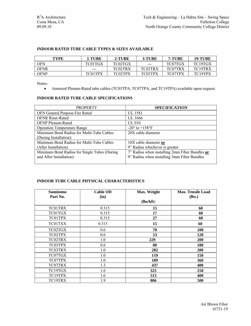
R2A Architecture Tech & Engineering – La Habra Site – Swing Space Costa Mesa, CA Fullerton College 09.09.10 North Orange County Community College District INDOOR RATED TUBE CABLE TYPES & SIZES AVAILABLE
TYPE 1-TUBE 2-TUBE 3-TUBE 7-TUBE 19-TUBE OFN TC01TGX TC02TGX --- TC07TGX TC19TGX OFNR --- TC02TRX TC03TRX TC07TRX TC19TRX OFNP TC01TPX TC02TPX TC03TPX TC07TPX TC19TPX Notes:
• Armored Plenum-Rated tube cables (TC03TPA, TC07TPA, and TC19TPA) available upon request. INDOOR RATED TUBE CABLE SPECIFICATIONS
PROPERTY SPECIFICATION OFN General Purpose Fire Rated UL 1581 OFNR Riser-Rated UL 1666 OFNP Plenum-Rated UL 910 Operation Temperature Range -20° to +158°F Minimum Bend Radius for Multi-Tube Cables (During Installation):
20X cable diameter
Minimum Bend Radius for Multi-Tube Cables (After Installation)
10X cable diameter or 9” Radius whichever is greater
Minimum Bend Radius for Single Tubes (During and After Installation):
7” Radius when installing 2mm Fiber Bundles or 9” Radius when installing 3mm Fiber Bundles
INDOOR TUBE CABLE PHYSICAL CHARACTERISTICS
Sumitomo Part No.
Cable OD (in)
Max. Weight
(lbs/kft)
Max. Tensile Load (lbs.)
TC01TBX 0.315 15 60 TC01TGX 0.315 17 60 TC01TPX 0.315 27 60 TC01TXX 0.315 15 60 TC02TGX 0.6 70 100 TC02TPX 0.6 53 120 TC02TRX 1.0 229 200 TC03TPX 0.6 80 180 TC03TRX 1.0 282 200 TC07TGX 1.0 119 150 TC07TPX 1.0 189 360 TC07TRX 1.3 437 400 TC19TGX 1.6 325 250 TC19TPX 1.6 513 400 TC19TRX 1.9 806 500
Air Blown Fiber 16721-19

R2A Architecture Tech & Engineering – La Habra Site – Swing Space Costa Mesa, CA Fullerton College 09.09.10 North Orange County Community College District INDOOR TUBE CABLE STANDARD REEL DATA
Sumitomo Part No.
Std Reel
Length (ft)
Std Reel
H x W (in)
Minimum Drum
Diameter (in)
Std Reel
Weight (lbs) Empty
Std Reel
Weight (lbs) Full
TC01TBX --- --- --- --- --- TC01TGX 1000 25 x 13 20 17 34 TC01TPX 1000 41 x 6 36 33 60 TC01TXX 500 17 x 5 5 1 16 TC02TGX 1000 36 x 34 18 66 136 TC02TPX 1000 54 x 10 40 105 158 TC02TRX 1000 54 x 20 40 116 345 TC03TPX 1000 54 x 20 40 116 196 TC03TRX 1000 54 x 36 40 137 419 TC07TGX 1000 54 x 20 40 116 235 TC07TPX 1000 54 x 20 40 116 305 TC07TRX 1000 54 x 36 40 137 574 TC19TGX 1000 64 x 40 46 248 573 TC19TPX 1000 64 x 40 46 248 761 TC19TRX 1000 60 x 48 40 246 1052
Notes:
• Cut Lengths are also available. Contact SEL or FutureFLEX® Distributor for additional information. • Maximum Reel Length tolerances are +5%. • All Reel Widths shown are approximate values only and measured from outside-of-flange to outside-of-
flange. • If tube cable is re-spooled, the Minimum Drum Diameter of the new reel SHALL be as shown to avoid
damaging tube cable product • All Empty and Full Reel Weights shown are approximate values only.
INDOOR TUBE CABLE MAXIMUM REEL DATA
Sumitomo Part No.
Max Reel
Length (ft)
Max Reel
H x W (in)
Minimum Drum
Diameter (in)
Max Reel
Weight (lbs) Empty
Max Reel
Weight (lbs) Full
TC01TBX 3300 28 x 20 20 18 68 TC01TGX 3000 28 x 20 20 18 69 TC01TPX 3000 54 x 10 40 105 186 TC01TXX --- --- --- --- --- TC02TGX 3000 36 x 34 18 66 276 TC02TPX 3000 54 x 36 40 137 296 TC02TRX 3000 60 x 48 40 246 933 TC03TPX 3000 54 x 36 40 137 377 TC03TRX 3000 60 x 48 40 246 1092 TC07TGX 3000 60 x 48 40 246 603 TC07TPX 3000 60 x 48 40 246 813 TC07TRX 3000 72 x 40 46 309 1620 TC19TGX 3000 72 x 50 46 333 1308
Air Blown Fiber 16721-20

R2A Architecture Tech & Engineering – La Habra Site – Swing Space Costa Mesa, CA Fullerton College 09.09.10 North Orange County Community College District
TC19TPX 3000 72 x 50 46 333 1872 TC19TRX 3000 84 x 50 30 288 2706
Notes:
• Cut Lengths are also available. Contact SEL or FutureFLEX® Distributor for additional information. • Maximum Reel Length tolerances are +5%. • All Reel Widths shown are approximate values only and measured from outside-of-flange to outside-of-
flange. • If tube cable is re-spooled, the Minimum Drum Diameter of the new reel SHALL be as shown to avoid
damaging tube cable product • All Empty and Full Reel Weights shown are approximate values only.
OUTDOOR TUBE CABLES SEL PART NUMBER DESCRIPTION “TC02TOX” Sumitomo Part Number (typical) “TC” Tube Cable “01, 02, etc.” Number of Individual Tubes “TOX” Tube Cable Description
OUTDOOR “DIELECTRIC CORE” TUBE CABLE DESCRIPTIONS & APPLICATIONS
TOX TOD MSOS AOX TAX * Dry to damp environments
Dry to damp environments
Dry to damp environments
Dry to damp environments
Dry to damp environments
Duct, direct buried applications
Duct, direct buried applications
Aerial, duct, direct buried applications
Duct, direct buried applications
Duct, direct buried applications Extremely rugged, high crush resistance
Dielectric core
Water-blocking tape
Polyethylene outer jacket
Dielectric core
Water-blocking tape
Polyethylene outer jacket
Dielectric core
Water-blocking tape High-performance outer jacket for enhanced thermal stability
Dielectric core
Water-blocking tape Polyethylene outer jacket
Dielectric core
Water-blocking tape Polyethylene outer jacket
FRP (fiber reinforced plastic)
Ultra-high performance tubes
Corrugated steel tape armor for
Extra heavy duty interlocked
Air Blown Fiber 16721-21

R2A Architecture Tech & Engineering – La Habra Site – Swing Space Costa Mesa, CA Fullerton College 09.09.10 North Orange County Community College District
central strength member
with low friction liners
rodent protection galvanized steel armor jacket
Grounding & Bonding required
Grounding & Bonding required
Notes:
• TAX-type Tube Cable is a non-standard product. Use TLA-type Tube Cable as alternative.
OUTDOOR “METALLIC CORE” TUBE CABLE DESCRIPTIONS & APPLICATIONS
TLW LWS TLA Flooded environments Flooded environments Flooded environments Duct, direct buried applications Duct, direct buried applications Duct, direct buried applications
Extremely rugged, high crush resistance
Metallic core Water blocking tape Laminated Aluminum Polyethylene (LAP) wrap Polyethylene outer jacket
Metallic core Water blocking tape Laminated Aluminum Polyethylene (LAP) wrap Polyethylene outer jacket
Metallic core Water blocking tape Laminated Aluminum Polyethylene (LAP) wrap Polyethylene outer jacket
Corrugated steel tape armor for rodent protection
Extra heavy duty interlocked galvanized steel armor jacket
Grounding & Bonding recommended
Grounding & Bonding recommended
Grounding & Bonding recommended
OUTDOOR TUBE CABLE TYPES & SIZES AVAILABLE
TYPE 2-TUBE 4-TUBE 7-TUBE 19-TUBE OSP --- --- TC07AOX --- OSP --- --- TC07LWS --- OSP - AERIAL TC02MSOS TC04MSOS TC07MSOS TC19MSOS OSP --- --- TC07TAX * TC19TAX * OSP --- --- TC07TLA TC19TLA OSP --- --- TC07TLW TC19TLW OSP --- TC04TOD --- --- OSP TC02TOX --- TC07TOX TC19TOX Notes:
• TAX-type Tube Cable is a non-standard product. Use TLA-type Tube Cable as alternative. OUTDOOR RATED TUBE CABLE SPECIFICATIONS
PROPERTY SPECIFICATION Operation Temperature Range -40° to +158°F Minimum Bend Radius for Multi-Tube Cables (During Installation):
20X cable diameter
Minimum Bend Radius for Multi-Tube Cables (After Installation):
10X cable diameter
Air Blown Fiber 16721-22

R2A Architecture Tech & Engineering – La Habra Site – Swing Space Costa Mesa, CA Fullerton College 09.09.10 North Orange County Community College District OUTDOOR TUBE CABLE PHYSICAL CHARACTERISTICS
Sumitomo Part No.
Cable OD (in)
Max. Weight
(lbs/kft)
Max. Tensile Load (lbs.)
TC02MSOS 0.9 89 200 TC02TOX 0.9 87 200
TC04MSOS 0.9 141 200 with standard
basket-weave grip, 500 with pulling eye
TC04TOD 0.9 137 200 with standard
basket-weave grip, 500 with pulling eye
TC07AOX 1.4 438 500 TC07LWS 1.4 479 400
TC07MSOS 1.1 196 400 TC07TAX * 1.5 825 500 TC07TLA 1.5 870 400 TC07TLW 1.1 223 400 TC07TOX 1.1 205 400
TC19MSOS 1.7 399 500 TC19TAX * 2.1 1152 500 TC19TLA 2.1 1650 500 TC19TLW 1.8 463 500 TC19TOX 1.7 443 500
Notes:
• TAX-type Tube Cable is a non-standard product. Use TLA-type Tube Cable as alternative.
OUTDOOR TUBE CABLE STANDARD REEL DATA
Sumitomo Part No.
Std Reel
Length (ft)
Std Reel
H x W (in)
Minimum Drum
Diameter (in)
Std Reel
Weight (lbs) Empty
Std Reel
Weight (lbs) Full
TC02MSOS 1000 36 x 17 18 55 144 TC02TOX 1000 36 x 17 18 55 142
TC04MSOS 1000 54 x 36 40 137 278 TC04TOD 1000 54 x 36 40 137 274 TC07AOX 1000 60 x 48 40 246 684 TC07LWS 1000 60 x 48 40 246 725
TC07MSOS 1000 54 x 36 40 137 333 TC07TAX * 1000 64 x 40 46 248 1073 TC07TLA 1000 64 x 40 46 248 1118 TC07TLW 1000 54 x 36 40 137 360 TC07TOX 1000 54 x 36 40 137 342
TC19MSOS 1000 64 x 40 46 248 647 TC19TAX * 1000 72 x 40 46 309 1461 TC19TLA 1000 72 x 40 46 309 1959 TC19TLW 1000 72 x 40 46 309 772
Air Blown Fiber 16721-23

R2A Architecture Tech & Engineering – La Habra Site – Swing Space Costa Mesa, CA Fullerton College 09.09.10 North Orange County Community College District
TC19TOX 1000 60 x 48 40 246 689 Notes:
• Cut Lengths are also available. Contact SEL or FutureFLEX® Distributor for additional information. • Standard Reel Length tolerances are +5%. • All Reel Widths shown are approximate values only and measured from outside-of-flange to outside-of-
flange. • If tube cable is re-spooled, the Minimum Drum Diameter of the new reel SHALL be as shown to avoid
damaging tube cable product • All Empty and Full Reel Weights shown are approximate values only. • TAX-type Tube Cable is a non-standard product. Use TLA-type Tube Cable as alternative.
OUTDOOR TUBE CABLE MAXIMUM REEL DATA
Sumitomo Part No.
Max Reel Length (ft)
Max Reel H x W (in)
Minimum Drum Diameter (in)
Max Reel Weight (lbs) Empty
Max Reel Weight (lbs) Full
TC02MSOS 3000 60 x 48 40 246 513 TC02TOX 3000 60 x 48 40 246 507 TC04MSOS 3000 60 x 48 40 246 669 TC04TOD 3000 60 x 48 40 246 657 TC07AOX 3000 72 x 50 46 333 1647 TC07LWS 3000 72 x 50 46 333 1770 TC07MSOS 3000 60 x 48 40 246 834 TC07TAX * 3000 72 x 50 46 333 2808 TC07TLA 3000 72 x 50 46 333 2943 TC07TLW 3000 60 x 48 40 246 915 TC07TOX 3000 60 x 48 40 246 861 TC19MSOS 3000 72 x 50 30 288 1485 TC19TAX * 2300 72 x 50 30 288 2938 TC19TLA 2300 72 x 50 30 288 4083 TC19TLW 3000 72 x 50 30 288 1677 TC19TOX 3000 72 x 50 30 288 1617
Notes:
• Cut Lengths are also available. Contact SEL or FutureFLEX® Distributor for additional information. • Maximum Reel Length tolerances are +5%. • All Reel Widths shown are approximate values only and measured from outside-of-flange to outside-of-
flange. • If tube cable is re-spooled, the Minimum Drum Diameter of the new reel SHALL be as shown to avoid
damaging tube cable product • All Empty and Full Reel Weights shown are approximate values only. • TAX-type Tube Cable is a non-standard product. Use TLA-type Tube Cable as alternative.
LOW SMOKE / ZERO HALOGEN (LS / ZH) TUBE CABLES
SEL PART NUMBER DESCRIPTION “TC01NA4” Sumitomo Part Number (typical) “TC” Tube Cable
Air Blown Fiber 16721-24

R2A Architecture Tech & Engineering – La Habra Site – Swing Space Costa Mesa, CA Fullerton College 09.09.10 North Orange County Community College District “01, 02, etc.” Number of Individual Tubes “NA4” Tube Cable Description LS / ZH TUBE CABLE DESCRIPTIONS & APPLICATIONS
NA3 Designed for US Navy LS/ZH shipboard applications Made from highly fire retardant; low smoke materials Single tube design: Each tube wrapped with tensile yarns and a TPN (Thermo Plastic Non-halogen) outer jacket Multiple tube cable designs: Each tube wrapped with salt water blocking tape and Kevlar yarn, filler rods placed between tubes, outer layer tubes overall wrapped with salt water blocking tape and Kevlar yarn, and a TPN (Thermo Plastic Non-halogen) outer jacket
Air Blown Fiber 16721-25

R2A Architecture Tech & Engineering – La Habra Site – Swing Space Costa Mesa, CA Fullerton College 09.09.10 North Orange County Community College District LS / ZH TUBE CABLE TYPES & SIZES AVAILABLE
TYPE 1-TUBE 7-TUBE 19-TUBE LS / ZH TC01NA4 TC07NA4 TC19NA4
LS / ZH TUBE CABLE SPECIFICATIONS
PROPERTY SPECIFICATION NA3 Burn Test IEEE 383 NA3 Operation Temperature Range -20° to +158°F Minimum Bend Radius for Multi-Tube Cables (During Installation):
20X cable diameter
Minimum Bend Radius for Multi-Tube Cables (After Installation):
10X cable diameter
Minimum Bend Radius for Single Tubes (During Installation):
20X cable diameter
Minimum Bend Radius for Single Tubes (After Installation):
7” Radius when installing 2mm Fiber Bundles or 9” Radius when installing 3mm Fiber Bundles
LS / ZH TUBE CABLE PHYSICAL CHARACTERISTICS
Sumitomo Part No.
Cable OD (in)
Max. Weight
(lbs/kft)
Max. Tensile Load (lbs.)
TC01NA4 0.455 65 60 TC07NA4 1.2 438 400 TC19NA4 2.0 895 500
LS / ZH TUBE CABLE STANDARD REEL DATA
Sumitomo Part No.
Std Reel
Length (ft)
Std Reel
H x W (in)
Minimum Drum
Diameter (in)
Std Reel
Weight (lbs) Empty
Std Reel
Weight (lbs) Full
TC01NA4 1000 30 x 13 20 18 83 TC07NA4 1000 54 x 36 40 137 575 TC19NA4 1000 60 x 48 40 246 1141
Notes:
• Cut Lengths are also available. Contact SEL or FutureFLEX® Distributor for additional information. • Standard and Maximum Reel Length tolerances are +5%. • All Reel Widths shown are approximate values only and measured from outside-of-flange to outside-of-
flange. • If tube cable is re-spooled, the Minimum Drum Diameter of the new reel SHALL be as shown to avoid
damaging tube cable product • All Empty and Full Reel Weights shown are approximate values only.
Air Blown Fiber 16721-26
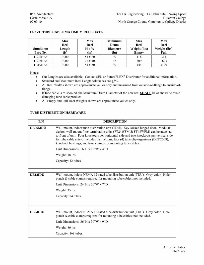
R2A Architecture Tech & Engineering – La Habra Site – Swing Space Costa Mesa, CA Fullerton College 09.09.10 North Orange County Community College District LS / ZH TUBE CABLE MAXIMUM REEL DATA
Sumitomo Part No.
Max Reel
Length (ft)
Max Reel
H x W (in)
Minimum Drum
Diameter (in)
Max Reel
Weight (lbs) Empty
Max Reel
Weight (lbs) Full
TC01NA4 3000 54 x 20 40 116 311 TC07NA4 3000 72 x 40 46 309 1623 TC19NA4 3000 84 x 50 30 444 3129
Notes:
• Cut Lengths are also available. Contact SEL or FutureFLEX® Distributor for additional information. • Standard and Maximum Reel Length tolerances are +5%. • All Reel Widths shown are approximate values only and measured from outside-of-flange to outside-of-
flange. • If tube cable is re-spooled, the Minimum Drum Diameter of the new reel SHALL be as shown to avoid
damaging tube cable product • All Empty and Full Reel Weights shown are approximate values only.
TUBE DISTRIBUTION HARDWARE
P/N DESCRIPTION
DE06MDU Wall-mount, indoor tube distribution unit (TDU). Key-locked hinged door. Modular design; wall-mount fiber termination units (FT24WFM & FT48WFM) can be attached to front of unit. Four knockouts per horizontal side and two knockouts per vertical side for tube cable entry. Includes instructions, four (4) tube clip organizers (DETC008), knockout bushings, and hose clamps for mounting tube cables.
Unit Dimensions: 16”H x 16”W x 4”D.
Weight: 18 lbs.
Capacity: 42 tubes.
DE12IDU Wall-mount, indoor NEMA 12-rated tube distribution unit (TDU). Gray color. Hole
punch & cable clamps required for mounting tube cables; not included.
Unit Dimensions: 24”H x 20”W x 7”D.
Weight: 35 lbs.
Capacity: 84 tubes.
DE24IDU Wall-mount, indoor NEMA 12-rated tube distribution unit (TDU). Gray color. Hole
punch & cable clamps required for mounting tube cables; not included.
Unit Dimensions: 36”H x 30”W x 9”D.
Weight: 86 lbs.
Capacity: 168 tubes.
Air Blown Fiber 16721-27

R2A Architecture Tech & Engineering – La Habra Site – Swing Space Costa Mesa, CA Fullerton College 09.09.10 North Orange County Community College District
DEDTTP Steel bracket and aluminum bar with plastic tube clip organizers for organizing
individual tubes. All mounting hardware and instructions included.
Capacity: Twelve 7-tube cables.
DEDTTP2 Steel bracket and aluminum bar with plastic tube clip organizers for organizing
individual tubes. All mounting hardware and instructions included.
Capacity: Six 19-tube cables.
DETC008 Black plastic tube clip organizer for up to 8 tubes. Mounts using screws provided.
DETCTB L-bracket for mounting up to two tube clip organizers (DETC008).
TUBE DISTRIBUTION HARDWARE (Continued)
P/N DESCRIPTION
DE08MC2 Clear plastic push/pull quick release pneumatic tube coupling for 8mm OD tube. 200 psi pressure rated. Ten couplings per pack.
DE08MB Brass push/pull quick release bulkhead pneumatic tube coupling for 8mm OD tube for panel mounting. 200 psi pressure rated. Ten bulkhead couplings per pack.
DE08MT
Black plastic push/pull quick release pneumatic tube tee coupling for 8mm OD tube. 200 psi pressure rated. Available individually.
DE08MA Slate plastic push/pull quick release pneumatic tube cap for 8mm OD tube. 200 psi
pressure rated. Seals opening of unoccupied tube. Recommended for indoor or outdoor application. Ten caps per pack.
DE06MP Orange plastic pneumatic tube plug for 6mm ID tube. Seals opening of unoccupied tube. Recommended for indoor application. Ten plugs per pack.
Air Blown Fiber 16721-28

R2A Architecture Tech & Engineering – La Habra Site – Swing Space Costa Mesa, CA Fullerton College 09.09.10 North Orange County Community College District TUBE DISTRIBUTION HARDWARE (Continued)
P/N DESCRIPTION
DE04HS1 Heat shrink end cap for 2- to 4-tube cables. Seals tube cable end to prevent contamination entry. Heat gun or torch required for installation.
DE07HS1 Heat shrink end cap for 7-tube cables. Seals tube cable end to prevent contamination entry. Heat gun or torch required for installation.
DE19HS1 Heat shrink end cap for 19-tube cables (except riser tube cable TC19TRX). Seals tube cable end to prevent contamination entry. Heat gun or torch required for installation.
DE19HS2 Heat shrink end cap for 19-tube riser cable TC19TRX. Seals tube cable end to prevent contamination entry. Heat gun or torch required for installation.
DE02T0X Tapered rubber insert for 2-tube (TC02TOX) cable installation using Hubbell Grip No. 074011251.
DE04T0D Tapered rubber insert for 4-tube (TC04TOD) cable installation using Hubbell Grip No.
07401026.
DE5KCAP Aluminum end cap sealing disc for unoccupied 2-, 4-, and 7-tube Kellems® Grips with
Form 5 Size compression nut:
074011251 (TC02TOX)
07401026 (TC04TOD)
07401027 (TC07TOX)
07401028 (TC07NA3)
07401032 (TC07AOX & TC07LWS)
DE6KCAP Aluminum end cap sealing disc for unoccupied 7- and 19-tube Kellems® Grips with
Form 6 Size compression nut:
07401033 (TC07TAX & TC07TLA)
07401034 (TC19TOX & TC19TLW)
Air Blown Fiber 16721-29

R2A Architecture Tech & Engineering – La Habra Site – Swing Space Costa Mesa, CA Fullerton College 09.09.10 North Orange County Community College District
DE7KCAP Aluminum end cap sealing disc for unoccupied 19-tube Kellems® Grips with Form 7 Size compression nut:
074011032 (TC19NA3)
074011033 (TC19TAX & TC19TLA)
TUBE DISTRIBUTION HARDWARE (Continued)
P/N DESCRIPTION
DE00SPL Tube cable splice kit for 2- to 4-tube cables. Includes cold shrink splice sleeve, mastic tape, water-blocking tape, four tube couplings (DE08MC2), and instructions.
DE01SPL Tube cable splice kit for 7- tube cables. Includes cold shrink splice sleeve, mastic tape, water-blocking tape, seven tube couplings (DE08MC2), and instructions.
DE02SPL Tube cable splice kit for 19-tube cables. Includes cold shrink splice sleeve, mastic tape, water-blocking tape, nineteen tube couplings (DE08MC2), and instructions.
FIBER AND FIBER BUNDLES
SEL PART NUMBER DESCRIPTION FB02SX Sumitomo Part Number (typical) “FB” Fiber “Bundle” “FR” Fiber “Ribbon” “02, 04, etc.” Number of Individual Fibers “SX” Single Mode Fiber “SR” Radiation Hardened Single Mode Fiber “M5” 50 / 125 Multi-mode Fiber (Standard Grade; 1 Gigabit)) “G53” 50 / 125 Multi-mode Fiber (Extended Grade; 10 Gigabit 300 m) “G55” 50 / 125 Multi-mode Fiber (Maximum Grade; 10 Gigabit 500 m) “M6” 62.5 / 125 Multi-mode Fiber (Standard Grade) “R6” Radiation Hardened 62.5 / 125 Multi-mode Fiber FIBER BUNDLE TYPES & SIZES AVAILABLE
TYPE 2-FIBER 4-FIBER 6-FIBER 12-FIBER 18-FIBER SX FR02SX FB04SX FB06SX FB12SX FB18SX SR FR02SR FB04SR FB06SR FB12SR FB18SR M5 FB02M5 FB04M5 FB06M5 FB12M5 FB18M5
Air Blown Fiber 16721-30

R2A Architecture Tech & Engineering – La Habra Site – Swing Space Costa Mesa, CA Fullerton College 09.09.10 North Orange County Community College District
G53 FB02G53 FB04G53 FB06G53 FB12G53 FB18G53 G55 FB02G55 FB04G55 FB06G55 FB12G55 FB18G55 M6 FR02M6 FB04M6 FB06M6 FB12M6 FB18M6
R6 FB02R6 FB04R6 FB06R6 FB12R6 FB18R6
SINGLE MODE FIBER & FIBER BUNDLE SPECIFICATIONS
PROPERTY SPECIFICATION Fiber Bundle Jacket material Polyethylene Extruded Foam (PEF) Fiber Bundle Jacket color Yellow
Core diameter 8.3 micron
Cladding diameter 125 micron
Buffer / acrylate diameter 250 micron Maximum Dispersion at 1310 / 1550 nm < 3.2 / 18.0 ps/nm-km Index of Refraction EIA/TIA-455-44 Test Procedure
1310 nm 1550 nm
1.466 1.467
Operation Temperature Range (for Fiber Bundle Assembly)
-40° to +158°F
Minimum Fiber Bundle Bend Radius 1.5”
FIBER AND FIBER BUNDLES (Continued)
50 MICRON MULTI-MODE FIBER & FIBER BUNDLE SPECIFICATIONS
PROPERTY SPECIFICATION Fiber Bundle Jacket material Polyethylene Extruded Foam (PEF)
Fiber Bundle Jacket color White
Core diameter 50 micron
Cladding diameter 125 micron
Buffer / acrylate diameter 250 micron Maximum Attenuation at 850 / 1300 nm < 3.5 / 1.5 dB/km Fiber Bandwidth at 850 / 1300 nm > 500 / 500 MHz-km
Std. Grade 850 nm 1300 nm
500 MHz*km 500 MHz*km
Min. Bandwidth (overfilled launch)
Ext. Grade 850 nm 1300 nm
1500 MHz*km 500 MHz*km
Air Blown Fiber 16721-31

R2A Architecture Tech & Engineering – La Habra Site – Swing Space Costa Mesa, CA Fullerton College 09.09.10 North Orange County Community College District
Max. Grade 850 nm 1300 nm 3000
MHz*km
500 MHz*km Std. Grade 850 nm
1310 nm 550 m 550 m
Ext. Grade 850 nm 1310 nm
1000 m 600 m
Min. Gigabit Ethernet Distance
Max. Grade 850 nm 1310 nm
1000 m 600 m
Std. Grade 850 nm 1310 nm
N/A N/A
Ext. Grade 850 nm 1310 nm
300 m 300 m
Min. 10-Gigabit Ethernet Distance
Max. Grade 850 nm 1310 nm
500 m 300 m
Group Index of Refraction EIA/TIA-455-44 Test Procedure
850 nm 1300 nm
1.483 1.479
Operation Temperature Range (for Fiber Bundle Assembly)
-40° to +158°F
Minimum Fiber Bundle Bend Radius 1.5”
FIBER AND FIBER BUNDLES (Continued)
62.5 MICRON MULTI-MODE FIBER & FIBER BUNDLE SPECIFICATIONS
PROPERTY SPECIFICATION Fiber Bundle Jacket material Polyethylene Extruded Foam (PEF)
Fiber Bundle Jacket color Blue
Core diameter 62.5 micron
Cladding diameter 125 micron
Buffer / acrylate diameter 250 micron Maximum Attenuation at 850 / 1300 nm < 3.5 / 1.5 dB/km Minimum Bandwidth at 850 / 1300 nm > 220 / 600 MHz-km
Std. Grade 850 nm 1300 nm
300 m 500 m
Min. Gigabit Ethernet Distance
Ext. Grade 850 nm 1300 nm
500 m 1000 m
Group Index of Refraction EIA/TIA-455-44 Test Procedure
850 nm 1300 nm
1.496 1.491
Operation Temperature Range (for Fiber Bundle Assembly)
-40° to +158°F
Air Blown Fiber 16721-32

R2A Architecture Tech & Engineering – La Habra Site – Swing Space Costa Mesa, CA Fullerton College 09.09.10 North Orange County Community College District Minimum Fiber Bundle Bend Radius 1.5”
FIBER BUNDLE REEL DATA
Sumitomo Part No.
Fiber Bundle
OD (mm)
Small Reel
Length (ft)
Small Reel
Weight (lbs)
Small Reel
H x W (in)
Large Reel
Length (ft)
Large Reel
Weight (lbs)
Large Reel
H x W (in)
FB02XX or FR02XX
2 7000 16.5 16 x 11 14000 36 20 x 12
FB04XX 2 7000 16.5 16 x 11 14000 36 20 x 12 FB06XX 2 7000 16.5 16 x 11 14000 36 20 x 12 FB12XX 3 3500 19 16 x 11 7000 41 20 x 12 FB18XX 3 3500 19 16 x 11 7000 41 20 x 12 Notes:
• Cut lengths are also available. Contact SEL or FutureFLEX® Distributor for additional information. • Standard reel length tolerances are +2% / -0%.
FIBER AND FIBER BUNDLES (Continued
ABF FIBER COLORS 2-Fiber Ribbon (Standard Ribbonized Coating)
1st Pos 2nd Pos Blue Orange No Ripcord
2-Fiber Bundles (1 Nylon Sub-Unit)
1st Pos 2nd Pos 3rd Pos 4th Pos 5th Pos 6th Pos 7th Pos Blue Ripcord Ripcord Orange Ripcord Ripcord Ripcord
4-Fiber Bundles (1 Nylon Sub-Unit)
1st Pos 2nd Pos 3rd Pos 4th Pos 5th Pos 6th Pos 7th Pos Blue Orange Ripcord Green Brown Ripcord Ripcord
6-Fiber Bundles (1 Nylon Sub-Unit)
1st Pos 2nd Pos 3rd Pos 4th Pos 5th Pos 6th Pos 7th Pos Blue Orange Green Brown Slate Ripcord White
12-Fiber Bundles (3 Nylon Sub-Units)
1st Pos 2nd Pos 3rd Pos 4th Pos 5th Pos 6th Pos 7th Pos Blue Orange Ripcord Green Brown Ripcord Ripcord Slate White Ripcord Red Black Ripcord Ripcord
Yellow Violet Ripcord Rose Aqua Ripcord Ripcord 18-Fiber Bundles (3 Nylon Sub-Units)
1st Pos 2nd Pos 3rd Pos 4th Pos 5th Pos 6th Pos 7th Pos
Air Blown Fiber 16721-33

R2A Architecture Tech & Engineering – La Habra Site – Swing Space Costa Mesa, CA Fullerton College 09.09.10 North Orange County Community College District
Blue Orange Green Brown Slate Ripcord Red Blue Orange Green Brown Slate Ripcord Yellow Blue Orange Green Brown Slate Ripcord Violet
Note: All Ripcords are Black Polyester
FIBER TERMINATION HARDWARE
P/N DESCRIPTION
FT24WFM 24-port wall-mount, indoor fiber termination unit (FTU). Key locked maintenance door and magnetic user access door. Modular design; can be attached to front of small tube distribution unit (TDU) (DE06MDU).
Unit Dimensions: 16”H x 16”W x 4”D.
Weight: 20 lbs.
Capacity: Four EIA standard 6-pack panels/four splice trays (not included).
FT48WFM 48-port wall-mount, indoor fiber termination unit (FTU). Key locked maintenance door and 1/4 turn latched access door. Modular design – can be attached to front of small tube distribution unit (TDU) (DE06MDU).
Unit Dimensions: 16”H x 16”W x 6”D.
Weight: 22 lbs.
Capacity: Eight EIA standard 6-pack panels/four splice trays (not included).
Air Blown Fiber 16721-34

R2A Architecture Tech & Engineering – La Habra Site – Swing Space Costa Mesa, CA Fullerton College 09.09.10 North Orange County Community College District
FIBER TERMINATION HARDWARE (Continued)
P/N DESCRIPTION
FT18RFS Rack-mount fiber termination unit. Fits both 19” and 23” equipment racks. Low profile. Includes one 24-fiber splice tray.
Unit dimensions: 1.75”H x 17”W x 12”D.
Weight: 10 lbs.
Capacity: 18 fibers.
FT36RFS Rack-mount fiber termination unit. Fits both 19” and 23” equipment racks. Includes three 12-fiber splice trays.
Unit dimensions: 3.5”H x 17”W x 12”D.
Weight: 13 lbs.
Capacity: 36 fibers.
FT48RFS Rack-mount fiber termination unit. Fits both 19” and 23” equipment racks. Includes four 12-fiber splice trays.
Unit dimensions: 7”H x 17”W x 12”D.
Weight: 20 lbs.
Capacity: 48 fibers.
FT72RFS Rack-mount fiber termination unit. Fits both 19” and 23” equipment racks. 72-fiber capacity. Includes six 12-fiber splice trays.
Unit dimensions: 10.5”H x 17”W x 12”D.
Weight: 25 lbs.
Capacity: 72 fibers.
Air Blown Fiber 16721-35

R2A Architecture Tech & Engineering – La Habra Site – Swing Space Costa Mesa, CA Fullerton College 09.09.10 North Orange County Community College District
FIBER TERMINATION HARDWARE (Continued)
P/N DESCRIPTION
FT18RFT Rack-mount fiber termination unit. Fits both 19” and 23” equipment racks. Low profile. For field termination only.
Unit dimensions: 1.75”H x 17”W x 12”D.
Weight: 9 lbs.
Capacity: 18 fibers.
FT36RFT Rack-mount fiber termination unit. Fits both 19” and 23” equipment racks. For field termination only.
Unit dimensions: 3.5”H x 17”W x 12”D.
Weight: 11 lbs.
Capacity: 36 fibers.
FT72RFT Rack-mount fiber termination unit. Fits both 19” and 23” equipment racks. For field termination only.
Unit dimensions: 5.25”H x 17”W x 12”D.
Weight: 17 lbs.
Capacity: 72 fibers.
FT144RFT Rack-mount fiber termination unit. Fits both 19” and 23” equipment racks. For field termination only.
Unit dimensions: 10.5”H x 17”W x 12”D.
Weight: 24 lbs.
Capacity: 144 fibers.
Air Blown Fiber 16721-36

R2A Architecture Tech & Engineering – La Habra Site – Swing Space Costa Mesa, CA Fullerton College 09.09.10 North Orange County Community College District
FIBER TERMINATION HARDWARE (Continued)
P/N DESCRIPTION
FT6SCS2 EIA standard push/pull-mount SC 6-pack panel for fiber termination units.
FT6SCS2 EIA standard push/pull-mount SC 6-pack panel for fiber termination units.
FT6FCS2 EIA standard push/pull-mount FC 6-pack panel for fiber termination units.
FTBLNK2 EIA standard push/pull-mount blank plate panel for fiber termination units.
FT12FHL Twelve position splice tray for heat-shrink or mechanical splices. Aluminum with clear plastic cover.
FT18FHL Eighteen position splice tray for standard fusion splices. Aluminum with clear plastic cover.
FT24SPL Adhesive mount splice tray holder for four splice trays.
Air Blown Fiber 16721-37

R2A Architecture Tech & Engineering – La Habra Site – Swing Space Costa Mesa, CA Fullerton College 09.09.10 North Orange County Community College District
FIBER TERMINATION HARDWARE (Continued)
P/N DESCRIPTION
FTFLD1 Field termination kit for 6-fiber bundle. Includes bushing, tube, and splitter with six 3mm color-coded sub-units. Kevlar and outer PVC jacket bonded to splitter. Includes instructions.
FTFLD3 Field termination kit for 18-fiber bundle. Includes bushing, tube, and splitter with eighteen 3mm color-coded sub-units. Kevlar and outer PVC jacket bonded to splitter. Includes instructions.
FTFLD06 Field termination kit for 6-fiber bundle. Includes splitter with six 900 micron color-coded sub-units. Includes instructions.
FTFLD12 Field termination kit for 12-fiber bundle. Includes splitter with twelve 900 micron clear sub-units. Includes instructions.
FTFLD18
Field termination kit for 18-fiber bundle. Includes splitter with eighteen 900 micron color-coded sub-units. Includes instructions.
FT2MFB Red rubber tapered fiber bushing for 2-, 4-, or 6-fiber bundles (2mm OD). Seals opening of occupied tube at termination locations. Available individually.
FT3MFB Black rubber tapered fiber bushing for 12- and 18-fiber bundles (3mm OD). Seals opening of occupied tube at termination locations. Available individually.
Air Blown Fiber 16721-38

R2A Architecture Tech & Engineering – La Habra Site – Swing Space Costa Mesa, CA Fullerton College 09.09.10 North Orange County Community College District
FIBER TERMINATION HARDWARE (Continued)
P/N DESCRIPTION
FTSSC1M Simplex SC pigtail. Single-mode fiber. One meter length.
FT6SC1M Simplex SC pigtail. 62.5 micron multimode fiber. One meter length.
FT6ST1M Simplex ST pigtail. 62.5 micron multimode fiber. One meter length.
FTSSC3M Simplex SC pigtail. Single-mode fiber. Three meters length.
FT6SC3M Simplex SC pigtail. 62.5 micron multimode fiber. Three meters length.
FT6ST3M Simplex ST pigtail. 62.5 micron multimode fiber. Three meters length.
FTSSC3J Simplex SC to SC jumper. Single-mode fiber. Three meters length.
FT6SC3J Simplex SC to SC jumper. 62.5 micron multimode fiber. Three meters length.
FT6ST3J Simplex ST to ST jumper. 62.5 micron multimode fiber. Three meters length.
BLOWING EQUIPMENT, TOOLS, & MISCELLANEOUS ACCESSORIES
Air Blown Fiber 16721-39

R2A Architecture Tech & Engineering – La Habra Site – Swing Space Costa Mesa, CA Fullerton College 09.09.10 North Orange County Community College District
P/N DESCRIPTION
BE200RM
Blowing equipment monthly lease. Includes transit case with blowing head and payoff stand assembly and the following items:
• One pressure regulator assembly with quick-release 8mm tubing adapter (BEREG01)
• One filter/regulator assembly with payoff counter • One motor rate control valve • One exhaust muffler • One ½” x 14” steel shaft • Two reel payoff cams (fit large and small fiber reels) • One fiber bundle guide assembly • One toolbox • Two red 2- to 6-fiber bundle (2mm OD) drive wheels (BE02DW) • Two black 12- or 18-fiber bundle (3mm OD) drive wheels (BE03DW) • One black 2- to 6-fiber bundle (2mm OD) air seal (BE02SL) • One black 12- or 18-fiber bundle (3mm OD) air seal (BE03SL) • One red 2- to 6-fiber bundle (2mm OD) blowing tip (BE2MFT) • One black 12- or 18-fiber bundle (3mm OD) blowing tip (BE3MFT) • One tubing cutter (BETC001) • Two tee couplings (DE08MT) • Two Allen wrenches (3/32” & 7/64”) • One bottle air motor cleaner fluid • Two 2-feet ¼ in. red tubing • One 6-feet ¼ in. white tubing • One 1-foot 8 mm clear tubing • Instructions included
BE200RY Blowing equipment yearly lease. Contents same as BE200RM.
Air Blown Fiber 16721-40

R2A Architecture Tech & Engineering – La Habra Site – Swing Space Costa Mesa, CA Fullerton College 09.09.10 North Orange County Community College District
BLOWING EQUIPMENT, TOOLS, & MISCELLANEOUS ACCESSORIES (Continued)
P/N DESCRIPTION
BE02DW
Replacement blowing head red fiber bundle drive wheels for installing 2- to 6-fiber bundles (2mm OD). Available in pairs.
BE03DW
Replacement blowing head black fiber bundle drive wheels for installing 12- and 18-fiber bundles (3mm OD). Available in pairs.
BE02SL
Replacement blowing head black rubber air seal for installing 2- to 6-fiber bundles (2mm OD). Available individually.
BE03SL
Replacement blowing head black rubber air seal for installing 12- and 18-fiber bundles (3mm OD). Available individually.
BE2MFT
Replacement red, reusable, threaded, aluminum fiber bundle blowing tip for installing 2- to 6-fiber bundles (2mm OD). Available individually.
BE3MFT
Replacement black, reusable, threaded, aluminum fiber bundle blowing tip for installing 12- and 18-fiber bundles (3mm OD). Available individually.
Air Blown Fiber 16721-41

R2A Architecture Tech & Engineering – La Habra Site – Swing Space Costa Mesa, CA Fullerton College 09.09.10 North Orange County Community College District
BLOWING EQUIPMENT, TOOLS, & MISCELLANEOUS ACCESSORIES (Continued)
P/N DESCRIPTION
BEPT001 Tube test kit. Includes bypass switch/valve, 0-200 psi portable hand-held pressure gage, and one hundred (100) 5mm plastic beads. (Tube Test Kit is not included in BE200RM or BE200RY.)
BEBB01P Replacement 5mm plastic beads for obstruction testing. One hundred (100) per pack.
BEREG01 Two-stage pressure regulator assembly. Includes quick release adapter with ¼” NPT (male and female) Type 15 connectors and ¼” NPT adapter to plastic push/pull quick release pneumatic coupling for 8 mm OD tube.
BETC001 Tubing cutter for individual tubes.
BETC00B Replacement blade for tubing cutter (BETC001). Available individually.
BETL01 Tube cable cutter for cutting up to 2-inch diameter tube cables. (Not to be used to cut steel strength members.)
BETL02 Replacement blade for tube cable cutter (BETL01). Available individually.
STANDARD FIBER BUNDLE BLOWING DISTANCES
2-, 4- & 6-FIBER BUNDLES (2mm OD) APPROX. DISTANCE
Air Blown Fiber 16721-42

R2A Architecture Tech & Engineering – La Habra Site – Swing Space Costa Mesa, CA Fullerton College 09.09.10 North Orange County Community College District
Air Blown Fiber 16721-43
OSP MSO Aerial tube cable
1200 meters or 4000 feet
All other OSP & TRX tube cables 1000 meters or 3300 feet
TGX, TPX, & NA3 tube cables 600 meters or 1950 feet
12- & 18-FIBER BUNDLES (3mm OD) APPROX. DISTANCE
OSP MSO Aerial tube cable 600 meters or 1950 feet
All other OSP & TRX tube cables 500 meters or 1650 feet
TGX, TPX & NA3 tube cables 300 meters or 1000 feet
Notes:
• All distances given are approximate using one (1) Blowing Head. • Several factors heavily influence actual blowing distances:
1. The location, number, and severity of bends in a tube cable run, 2. The fiber bundle size installed (2mm OD or 3mm OD), and 3. The tube cable type

R2A Architecture Tech & Engineering – La Habra Site – Swing Space Costa Mesa, CA Fullerton College 09.09.10 North Orange County Community College District
16725 – TELECOMMUNICATIONS CABLE
PART 1 - GENERAL
1.1 SECTION INCLUDES
A. Inter-building Copper Cable
B. Copper Riser Cable
C. Copper Station Cable
G. Inter-building Coaxial Cable – Not applicable.
H. Coaxial Distribution Cable – Not applicable.
I. Coaxial Station Cable – Not applicable.
J. Headend Cable – Not applicable.
1.2 RELATED SECTIONS
A. Contract Terms and Conditions
B. Section 16710 - Telecommunications - General Requirements
C. Section 16715 - Telecommunications - Acceptance Testing
D. Section 16720 - Telecommunications - Basic Materials and Methods E. Section 16721 – Telecommunication - Air Blown Fiber Basic Materials and Methods
F. Section 16760 - Telecommunications - Grounding and Bonding
1.3 APPLICABLE PUBLICATIONS
A. As defined in Section 16710 - Telecommunications General Requirements
1.4 SUBMITTALS
The Contractor shall submit the following materials to the Campus prior to the placement of cable:
A. Product data, including both product construction and performance specifications, for each type and configuration of cable to be supplied. In addition, the Contractor shall provide product data and installation instructions for all fire-stop materials.
B. Proof of Systimax Solutions Inc. SYSTIMAX® certification.
C. Copies of signed optical cable reel tests.
D. Proof of required licenses.
Telecommunications Cable 16725 - 1

R2A Architecture Tech & Engineering – La Habra Site – Swing Space Costa Mesa, CA Fullerton College 09.09.10 North Orange County Community College District
PART 2 - MATERIALS
The products listed in this section represent the standards for materials, workmanship, and performance for a NOCCCD project.
2.1. INTER-BUILDING COPPER CABLE (GEL-FILLED)
A. Material
(1) Application: Use for outside conduit and direct buried applications.
(2) Compliance: RUS Specification PE-39.
(3) Core Construction:
a. Conductors: Solid, annealed copper, 24 AWG unless noted on design documents.
b. Insulation: Solid, high density polyethylene, color coded in accordance with telephone industry standards.
c. Twisted Pairs: Insulated conductors twisted into pairs with varying lay lengths to minimize crosstalk. Standard capacitance of 83 to 87 nanofarads per mile and a staggered twist design.
d. Core Assembly: Cables of 25 pairs and less formed by assembling pairs together in a single group. Cables of more than 25 pairs formed by twisted pairs arranged in groups with each group having a color coded unit binder.
e. Filling Compound: Core assembly completely filled with ETPR compound, filling the interstices between the pairs and under the core tape.
f. Core Wrap: Non-hygroscopic dielectric tape applied longitudinally with an overlap.
(4) Qualpeth Sheath
a. Aluminum Shield: Corrugated, copolymer coated, .008" aluminum tape applied longitudinally with an overlap. The sheath interfaces are flooded with an adhesive water-blocking compound.
b. Jacket: Black, linear low-density polyethylene.
(5) Cable sizes defined in design documents.
B. Manufacturer: Systimax Solutions Inc.
2.2 COPPER RISER CABLE
A. Material
(1) Application: Use for placement in vertical risers in buildings and in general horizontal applications within buildings.
(2) Compliance: Bellcore Specification TS-TSY-000111, UL Listed Type MPR/CMR
Telecommunications Cable 16725 - 2

R2A Architecture Tech & Engineering – La Habra Site – Swing Space Costa Mesa, CA Fullerton College 09.09.10 North Orange County Community College District
(3) Core Construction:
a. Conductors: Solid-copper conductors, 24 AWG.
b. Insulation: Dual insulation consisting of an inner layer of foamed polyolefin surrounded by a solid PVC skin, color coded in accordance with telephone industry standards.
c. Twisted Pairs: Insulated conductors twisted into pairs with varying lay lengths to minimize crosstalk.
d. Core Assembly: Cable cores made up of 100 pair super-units consisting of four (4) 25 pair sub-units. Each group individually identifiable by color coded unit binders. Each 25 pair-unit within the 100 pair super-unit identified with a different binder color. (Note: “PIC MIRROR IMAGE” multi-unit identification used in cables over 900 pairs.)
e. Core Wrap: Non-hygroscopic dielectric tape applied longitudinally with an overlap.
(4) Alvyn Sheath:
a. Aluminum Shield: Corrugated, adhesive coated, 0.008" aluminum tape applied longitudinally with a n overlap.
b. Jacket: Gray, flame retardant PVC jacket bonded to the coated aluminum.
(5) Cable sizes defined in Contract Documents.
B. Manufacturer: Systimax Solutions Inc., Product Number: ARMM NCA 4051 xxx.
2.3 COPPER STATION CABLE
A. Material
(1) Use for voice applications to interconnect services from workstation to the wiring closet in a plenum or non-plenum rated space.
(2) CMP/MPP rated.
(3) Four pair, 24 AWG, Category 6, UTP, as defined by the EIA/TIA standards intended for use with transmission rates up to and including 100 Mbps.
(4) A different colored Category 6 cable is to be used consistently throughout the project for each different colored jack. Voice is to use white cable with the electrical ivory jack. Data-1 is to use yellow cable with the orange jack. Data-2 is to use blue cable (medium) with the gray jack.
B. Manufacturer: Systimax Solutions Inc., Plenum UL Verified Category 6, 2071 LAN Cable Gigaspeed XL
2.4 INTER-BUILDING AIR BLOWN FIBER OPTIC CABLE (MULTIMODE)
A. Materials
(1) Application: Use for placement in outside plant conduit between buildings.
Telecommunications Cable 16725 - 3
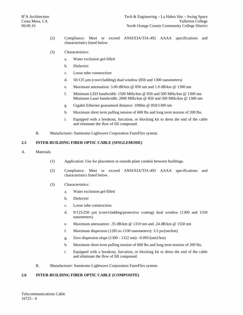
R2A Architecture Tech & Engineering – La Habra Site – Swing Space Costa Mesa, CA Fullerton College 09.09.10 North Orange County Community College District
(2) Compliance: Meet or exceed ANSI/EIA/TIA-492 AAAA specifications and characteristics listed below.
(3) Characteristics:
a. Water exclusion gel-filled
b. Dielectric
c. Loose tube construction
d. 50/125 µm (core/cladding) dual window (850 and 1300 nanometers)
e. Maximum attenuation: 3.00 dB/km @ 850 nm and 1.0 dB/km @ 1300 nm
f. Minimum LED bandwidth: 1500 MHz/km @ 850 and 500 MHz/km @ 1300 nm Minimum Laser bandwidth: 2000 MHz/km @ 850 and 500 MHz/km @ 1300 nm
g. Gigabit Ethernet guaranteed distance: 1000m @ 850/1300 nm
h. Maximum short term pulling tension of 600 lbs and long term tension of 200 lbs.
i. Equipped with a breakout, furcation, or blocking kit to dress the end of the cable and eliminate the flow of fill compound.
B. Manufacturer: Sumitomo Lightwave Corporation FutreFlex system.
2.5 INTER-BUILDING FIBER OPTIC CABLE (SINGLEMODE)
A. Materials
(1) Application: Use for placement in outside plant conduit between buildings.
(2) Compliance: Meet or exceed ANSI/EIA/TIA-492 AAAA specifications and characteristics listed below.
(3) Characteristics:
a. Water exclusion gel-filled
b. Dielectric
c. Loose tube construction
d. 9/125/250 µm (core/cladding/protective coating) dual window (1300 and 1550 nanometers)
e. Maximum attenuation: .35 dB/km @ 1310 nm and .24 dB/km @ 1550 nm
f. Maximum dispersion (1285 to 1330 nanometers): 3.5 ps/(nm/km)
g. Zero dispersion slope (1300 - 1322 nm): -0.095/(nm2/km)
h. Maximum short term pulling tension of 600 lbs and long term tension of 200 lbs.
i. Equipped with a breakout, furcation, or blocking kit to dress the end of the cable and eliminate the flow of fill compound.
B. Manufacturer: Sumitomo Lightwave Corporation FutreFlex system.
2.6 INTER-BUILDING FIBER OPTIC CABLE (COMPOSITE)
Telecommunications Cable 16725 - 4

R2A Architecture Tech & Engineering – La Habra Site – Swing Space Costa Mesa, CA Fullerton College 09.09.10 North Orange County Community College District
A. Materials
(1) Application: Use for placement in outside plant conduit between buildings.
(2) Compliance: Meet or exceed ANSI/EIA/TIA-492 AAAA specifications and characteristics listed below.
(3) Characteristics - Cable:
a. Combined multimode fibers and singlemode fibers under one cable sheath.
b. Water exclusion gel-filled
c. Dielectric
d. Loose tube construction
e. Maximum short term pulling tension of 600 lbs and long term tension of 200 lbs.
f. Equipped with a breakout, furcation, or blocking kit to dress the end of the cable and eliminate the flow of fill compound.
(4) Characteristics - Multimode Fibers:
a. 50um/12(5)µm (core/cladding) dual window (850 and 1300 nanometers)
b. Maximum attenuation: 3.00 dB/km @ 850 nm and 1.0 dB/km @ 1300 nm
g. Minimum LED bandwidth: 1500 MHz/km @ 850 and 500 MHz/km @ 1300 nm
Minimum Laser bandwidth: 2000 MHz/km @ 850 and 500 MHz/km @ 1300 nm
(5) Characteristics - Singlemode Fibers:
a. 9/125/250 µm (core/cladding/protective coating) dual window (1300 and 1550 nanometers)
b. Maximum attenuation: .35 dB/km @ 1310 nm and .24 dB/km @ 1550 nm
c. Maximum dispersion (1285 to 1330 nanometers): 3.5 ps/(nm/km)
d. Zero dispersion slope (1300 - 1322 nm): -0.095/(nm2/km)
B. Manufacturer: Sumitomo Lightwave Corporation FutureFlex system.
2.7 FIBER OPTIC RISER RATED CABLE (MULTIMODE)
A. Materials
(1) Application: Use for placement in vertical riser backbone within buildings.
(2) Compliance: Meet or exceed ANSI/ICEA S-83-596 per requirements of ANSI/TIA/EIA-568A specifications and characteristics listed below.
(3) Characteristics:
a. OFNR/FT4 rated for riser applications
b. Dielectric strength member
d. 50um/125 µm (core/cladding) dual window (850 and 1300 nanometers)
Telecommunications Cable 16725 - 5

R2A Architecture Tech & Engineering – La Habra Site – Swing Space Costa Mesa, CA Fullerton College 09.09.10 North Orange County Community College District
e. Maximum attenuation: 3.4 dB/km @ 850 nm and 1.0 dB/km @ 1300 nm
f. Minimum bandwidth: 200 MHz/km @ 850 and 500 MHz/km @ 1300 nm
g. .275 numerical aperture
h. Maximum short term pulling tension of 600 lbs and long term tension of 200 lbs.
i. Equipped with a breakout, furcation, or blocking kit to dress the end of the cable and eliminate the flow of fill compound.
B. Manufacturer: Sumitomo Lightwave Corporation FutureFlex system.
2.8 FIBER OPTIC RISER rated CABLE (SINGLEMODE)
A. Materials
(1) Application: Use for placement in vertical riser backbone within buildings.
(2) Compliance: Meet or exceed ANSI/ICEA S-83-596 per requirements of ANSI/TIA/EIA-568A specifications and characteristics listed below.
(3) Characteristics:
a. OFNR/FT4 rated for riser applications
b. 8.3/125/245 µm (core/cladding/protective coating) dual window (1300 and 1550 nanometers)
c. Maximum attenuation: .7 dB/km @ 1310 nm and .35 dB/km @ 1550 nm
d. Maximum dispersion (1285 to 1330 nanometers): 2.8 ps/(nm/km)
e. Zero dispersion slope (1300 - 1322 nm): -0.095/(nm2/km)
f. Maximum short term pulling tension of 600 lbs and long term tension of 200 lbs.
g. Equipped with a breakout, furcation, or blocking kit to dress the end of the cable and eliminate the flow of fill compound.
B. Manufacturer: Sumitomo Lightwave Corporation FutureFlex system.
2.9 FIBER OPTIC STATION CABLE (MULTIMODE)
A. Materials
(1) Application: Use for placement in fiber to the workstation within building a building.
(2) Compliance: Meet or exceed ANSI X3T9.5 PMD specifications and characteristics listed below.
(3) Characteristics:
a. Plenum Rated OFNP/FT6.
b. Dual optic, multimode cable intended for use with transmission rates up to and including 155 Mbps in a network with ATM standards.
c. 50um/125 µm (core/cladding) dual window (850 and 1300 nanometers)
d. Maximum attenuation: 3.4 dB/km @ 850 nm and 1.0 dB/km @ 1300 nm
Telecommunications Cable 16725 - 6

R2A Architecture Tech & Engineering – La Habra Site – Swing Space Costa Mesa, CA Fullerton College 09.09.10 North Orange County Community College District
e. Minimum bandwidth: 200 MHz/km @ 850 and 500 MHz/km @ 1300 nm
f. .275 numerical aperture
g. Strippable jacket and either a central strength member or high tensile strength yarn for mechanical protection.
h. Maximum short term pulling tension of 600 lbs and long term tension of 200 lbs.
B. Manufacturer: Systimax Solutions Inc., Multimode LazrSpeed 150 Series Building Cable Plenum Rated Series, Product Number: 5301-0XXA-HPAQ.
2.10 COAXIAL RISER CABLE
A. Not Applicable.
2.11 COAXIAL BACKBONE CABLE
A. Not Applicable.
2.12 COAXIAL STATION CABLE DROPS
A. Not Applicable.
2.13 HEADEND CABLE (HEC)
A. Not Applicable.
PART 3 - EXECUTION
3.1 GENERAL INSTALLATION
A. All installation work shall be performed according to published industry guidelines, rules, and regulations. If disputes occur, local, state, and national codes have precedence; then CSU polices and procedures; then standards such as EIA/TIA; then guidelines from firms such as Building Industry Consulting Services International (BICSI), AT&T, GTE, Systimax Solutions Inc. SYSTIMAX® and Northern Telecom; then finally, manufacturer recommendations.
B. The Contractor shall provide sufficient trained staff to monitor all work undertaken and to ensure that the requirements of these specifications are met throughout the installation process.
C. All tests will be conducted using equipment that has laboratory or manufacturer certified calibration within six months of the tests. The Contractor shall provide a signed copy of the calibration test results for each item of test equipment with the acceptance documentation..
D. All installation work will be of the highest quality. The Contractor shall at all times make every effort to conduct all installation work in a manner so as to minimize the impact on the facilities. Whenever possible, all work will be hidden behind finished materials and all surfaces will be returned to their original condition.
E. The Contractor shall provide and install all pathway and cable support hardware necessary to successfully complete the installation. This includes, but is not limited to, hangers, ladder racks, support brackets, conduit and sleeves, firestop materials, tie-wraps, and access openings such as core drills.
Telecommunications Cable 16725 - 7

R2A Architecture Tech & Engineering – La Habra Site – Swing Space Costa Mesa, CA Fullerton College 09.09.10 North Orange County Community College District
F. The Contractor shall ensure that only staff fully qualified to work on specific types of materials are allowed to undertake the required installation. Particularly, copper and fiber optic cable placement, termination, splicing, and testing shall only be undertaken by staff who are Systimax Solutions Inc. SYSTIMAX® certified.
G. The Contractor shall provide all hardware, software, and miscellaneous components necessary to provide a complete system.
H. The Contractor and Campus’s representative shall coordinate cutover schedules prior to installation. The work will be scheduled so that the voice and data networks will be out of service for a minimum period of time
I. No cables (copper, coaxial and / or fiber optic) will be spliced without written authorization from the Campus’s representative.
J. The bend radius of any cable installed must not exceed the manufactures specifications. In those cases, such as in wire mold, where the minimum radius cannot be maintained, a 90 degree fitting is to be used provided the performance criteria is not jeopardized.
3.2 INTER-BUILDING COPPER CABLE
A. The Inter-building cables shall be installed according to Systimax Solutions Inc. SYSTIMAX® Premises Distribution System procedures, by certified personnel.
B. Cables shall be routed in such a manner as to allow other maintenance activities to occur without damage to the cable. All cables shall be routed as close to walls as possible in vaults to reduce accidental damage. Cable routed through manholes shall be attached to the cable rack supports using “L” cable rack supports.
C. All cable runs installed in conduit or duct banks shall include a nylon pull cord (1/4 inch), tied off at each end of run, unless the conduit is full. A nylon or polyethylene pulling line shall be used in all fiber optics raceways. The pull cord shall be clearly labeled as “pulling line,” indicating source and destination.
D. Placement of cable in individual conduits shall be determined by the Contractor and Campus’s representative to ensure the best utilization of the distribution space. All conduits shall be pulled as full as possible without damage to the cable. All cables shall be secured to the wall of the BDFs, vaults, manholes, pull boxes, etc. using “L” cable rack supports.
E. All cables shall be clearly labeled with cable number (Campus’s representative to determine scheme), size, at each end of the cable, when it enters or leaves a conduit, and at 30 foot intervals when run in accessible areas such as tunnels, manholes, ceilings, etc.
F. All cables shall be placed using swivel pulling eyes to reduce cable coils.
G. All cables shall be routed with wide sweeps without bends or kinks in the cable or sheath. The minimum bending radius for all cable is sixteen (16) times the cable diameter or manufacturer’s specifications, whichever is greater.
H. Cuts and abrasions that penetrate the outer sheath of the cable shall be inspected by the Contractor and Campus’s representative to determine if the cable must be replaced or may be patched. Decisions regarding the suitability of cables damaged during placement will be the responsibility of the Contractor and Campus’s representative.
Telecommunications Cable 16725 - 8

R2A Architecture Tech & Engineering – La Habra Site – Swing Space Costa Mesa, CA Fullerton College 09.09.10 North Orange County Community College District
I. All cable shields shall be bonded end-to-end and grounded per AT&T/Systimax Solutions Inc. Telecommunications Electrical Protection Specification.
J. Filled cables shall be spliced into shielded protector tails. Cable splices shall be attached to walls using “B” cable rack and “L” cable rack supports. Splices shall be properly secured to the “L” support preventing detachment by external forces. Cable splices in utility tunnels may be placed in cable trays if available and adequate maintenance space is maintained. Otherwise the above supporting requirements apply. Splice cases shall be dressed and mounted to eliminate the movement of gel compound. All splice cases must be flooded with re-enterable compound.
K. Entrance Cables
(1) All cables shall enter a building through rigid metal or PVC conduit. Spare innerduct will be placed to fill the conduit to ensure maximum utilization of the conduit.
(2) A separate conduit with innerduct shall be used for fiber optic and coaxial cables.
(3) Cables shall not penetrate more than 50 feet (except in metallic conduit) before a conversion splice is made to fire resistant type cable (ARMM).
(4) Filled cable shall not be terminated on 110 hardware without a transition splice to fire resistant type cable (ARMM) or tip cables.
(5) All entrance cables and protectors shall be grounded per AT&T / Systimax Solutions Inc. Telecommunications Electrical Protection Specification (Select code 350-060) and have continuous sheath continuity.
L. All installed empty conduits shall be plugged with a neoprene or rubber duct plug to prevent water and/or gas seepage into a building or manhole. Conduit containing cable will be filled with the appropriate compound.
3.3 COPPER RISER CABLE
A. All riser cables shall be installed in a neat and orderly manner that provides the maximum amount of room for future cable additions. All riser conduits shall be pulled as full as possible. All cables shall be supported on each floor using at least three straps (not more than 30 inches apart) per floor. Riser cable shields shall be grounded on any floor in which pairs enter or leave the sheath. All shields shall be bonded end-to-end.
B. All riser conduits shall be sealed using a UL classified firestop. The Contractor shall provide a copy of the fire seal manufacturer’s installation instructions and rating information prior to inspection of the installed materials.
3.4 COPPER STATION CABLE
A. All station cables shall be neatly dressed, secured, and concealed throughout the installation. Cables shall be secured with plastic ties to a snug fit but shall not deform the cable geometry. Ties shall be of a plenum-rated material if cable is installed within a plenum ceiling space.
B. All station cables shall be secured a minimum of six (6) inches above the ceiling T-bar grid. Ceiling grid supports, electrical conduit, water pipes, and HVAC ducting may not be used to support cables. In those areas without adequate support structures, the Contractor shall install “J” hooks or additional ceiling grid hangers on five foot centers. No more than 12 individual cables
Telecommunications Cable 16725 - 9

R2A Architecture Tech & Engineering – La Habra Site – Swing Space Costa Mesa, CA Fullerton College 09.09.10 North Orange County Community College District
will be secured to a single ceiling hanger without the use of a two-inch wide saddle to eliminate strain on individual cables. Cables shall not be placed within 24 inches of overhead lights or any other potential source of electrical interference.
C. In any area in which a fire-rated wall, partition, floor, or ceiling is penetrated, the Contractor shall be responsible for creating the pathway and sealing around all cables and sleeves with a UL classified fire seal sufficient to return the structure to its original rating. Creation of such openings as are necessary for cable passage between locations as shown on the drawings shall be the responsibility of the Contractor. Any opening in a rated structure created by the Contractor that is larger than one inch in diameter shall be equipped with a metal sleeve secured and fire-stopped in place.
D. In station locations with walls that must be fished, the Contractor shall place a plaster wall retaining ring or metal supporting “ears” around the outlet location to secure the outlet and face plate. No exposed cable shall be permitted.
E. In locations where the wall will not be fished and surface-mount raceways are utilized, all raceways must be mechanically secured to the structure a minimum of every four feet, must be routed at right angles to nearby structures or wall corners, and shall be neatly installed and trimmed to fit into and around other existing moldings or pathways such as the ceiling area. Raceways shall be placed vertically only in corners of rooms and horizontal raceway placed at baseboard height to extend the cable run to the actual outlet location.
F. A sufficient maintenance loop (slack cable), neatly coiled and secured in the ceiling space above the BDF and IDF terminals, shall be placed for all station cables to allow for future rearrangement.
G. The Contractor is responsible for removing, replacing, and repairing ceiling tiles in order to route all cables. If the ceiling tiles are concealed spline, the tiles shall not be replaced until installation work in that area has been inspected and reviewed with Campus’s representative and approval given to re-fix the ceiling in place.
H. Voice and data station cables shall be terminated on insulated displacement hardware (e.g., AT&T 110) and shall be clearly marked with a unique identification number following the Campus’s standard.
3.5 FIBER OPTIC STATION CABLE
A. Not applicable.
3.6 COAXIAL RISER CABLE
A. Not applicable.
3.7 COAXIAL BACKBONE CABLE
A. Not applicable.
3.9 COAXIAL STATION CABLE
A. Not applicable.
3.10 HEADEND AND DISTRIBUTION CABLE INTERFACE
A. Not applicable.
Telecommunications Cable 16725 - 10

R2A Architecture Tech & Engineering – La Habra Site – Swing Space Costa Mesa, CA Fullerton College 09.09.10 North Orange County Community College District
Telecommunications Cable 16725 - 11
END OF SECTION

R2A Architecture Tech & Engineering – La Habra Site – Swing Space Costa Mesa, CA Fullerton College 09.09.10 North Orange County Community College District
TELECOMMUNICATIONS GROUNDING & BONDING - 16760
PART 1 - GENERAL
1.1 SECTION INCLUDES
A. Related Sections
B. Applicable Publications
C. Work Sequencing and Coordination
D. Telecommunications Submittals
E. Quality Assurance
F. Project Record Documents
G. Qualifications
H. Regulatory Requirements
I. Performance Requirements
J. Materials
K. Execution
1.2 RELATED SECTIONS
A. Division 16 Electrical Sections apply to this Section with the additions and modifications specified herein.
B. Section 16710 – Telecommunications - General Requirements
C. Section 16715 - Telecommunications - Acceptance Testing
D. Section 16720 - Telecommunications - Basic Materials and Methods E. Section 16720 - Telecommunications – Air Blown Fiber Basic Materials and Methods
E. Section 16725 - Telecommunications - Cable
1.3 APPLICABLE PUBLICATIONS
A. A. As defined in section 16710 - Telecommunications General Requirements.
B. Underwriters Laboratories, Inc. (UL) Publication:
(1) 83 Thermoplastic Insulated Wires
(2) 467 Grounding and Bonding
Telecommunications Grounding & Bonding 16760-1

R2A Architecture Tech & Engineering – La Habra Site – Swing Space Costa Mesa, CA Fullerton College 09.09.10 North Orange County Community College District
1.4 WORK SEQUENCING AND COORDINATION
A. The Contractor shall coordinate interconnection to the District’s existing grounding and bonding system with District’s representative. The existing grounding and bonding system will not be taken out of service during the District’s normal hours of operation. Any out of service activity shall be coordinated a minimum of two weeks in advance and shall occur after hours.
1.5 SUBMITTALS
The University shall receive the following Contractor submittals:
A. Product data for:
(1) Ground bus bars
(2) Conductors
(3) Connections (all types)
B. Test Reports for:
(1) Overall resistance to ground and resistance of each busbar
(2) Ground resistance measurements made at each MDF, BDF, IDF, and designated telecommunications space
C. Manufacturer's Instructions: include instructions for storage, handling, protection, examination, preparation and installation of exothermic connectors.
1.6 QUALITY ASSURANCE
A. All grounding and bonding system work shall be tested and documented as defined in Section 16715 - Telecommunications Acceptance Testing.
B. For products or workmanship specified by association, trade, Federal, or State Standards, the Contractor shall comply with the requirements of the standard, except when more rigid requirements required by applicable codes or District standards shall apply.
C. The Contractor shall conform to reference standard by date of issue current on final design documents.
1.7 PROJECT RECORD DOCUMENTS
A. The Contractor shall accurately record and submit to the District complete data regarding communication ground wire pathways, points of bonding, and point of connection to building grounds.
B. Antenna protector grounding shall indicate ground source, distance, and size of ground wire.
Telecommunications Grounding & Bonding 16760-2

R2A Architecture Tech & Engineering – La Habra Site – Swing Space Costa Mesa, CA Fullerton College 09.09.10 North Orange County Community College District
1.8 QUALIFICATIONS
A. Products specified in this Section shall be manufactured by a company with a minimum of three years’ documented experience specializing in manufacturing such products.
1.9 REGULATORY REQUIREMENTS
A. Telecommunications grounding and bonding shall conform to requirements of NFPA 70 and ANSI C2.
B. The Contractor shall furnish products listed and classified by Underwriters Laboratories, Inc. or testing firm acceptable to the campus as suitable for purpose specified and shown.
1.10 PERFORMANCE REQUIREMENTS
A. Point to Point Resistance: 0.5 ohms or less.
PART 2 MATERIALS
2.1 MATERIALS AND EQUIPMENT
A. Materials and equipment shall conform to the respective standards and to the Quality Standards stated herein. Electrical ratings shall be as indicated. Except where specifically indicated otherwise, the Contractor shall provide only new materials having all legally required approvals and/or labels. Materials shall conform to the requirements of UL 467 where applicable.
2.2 CONDUCTOR, UL 83
A. Ground and bonding conductors shall be green-insulated, soft-drawn stranded copper conductors, unless otherwise indicated, installed with sufficient slack to avoid breaking due to settlement and movement of conductors or attached points.
B. System grounding conductors shall be minimum of 3/0 AWG bare copper, unless otherwise indicated, and shall be continuous with no joints or splices.
2.3 CONNECTORS AND TERMINALS
A. Wire Connectors and Terminals for use with Copper Conductors: UL 486A.
Telecommunications Grounding & Bonding 16760-3
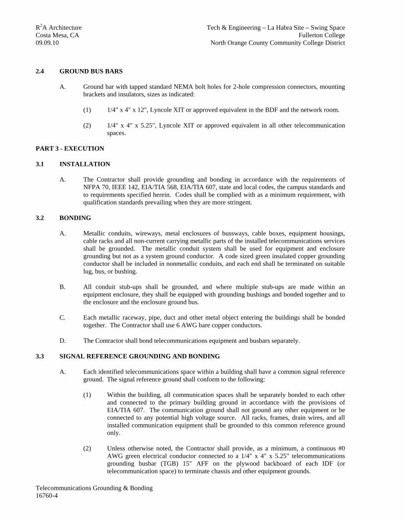
R2A Architecture Tech & Engineering – La Habra Site – Swing Space Costa Mesa, CA Fullerton College 09.09.10 North Orange County Community College District
2.4 GROUND BUS BARS
A. Ground bar with tapped standard NEMA bolt holes for 2-hole compression connectors, mounting brackets and insulators, sizes as indicated:
(1) 1/4" x 4" x 12", Lyncole XIT or approved equivalent in the BDF and the network room.
(2) 1/4" x 4" x 5.25", Lyncole XIT or approved equivalent in all other telecommunication spaces.
PART 3 - EXECUTION
3.1 INSTALLATION
A. The Contractor shall provide grounding and bonding in accordance with the requirements of NFPA 70, IEEE 142, EIA/TIA 568, EIA/TIA 607, state and local codes, the campus standards and to requirements specified herein. Codes shall be complied with as a minimum requirement, with qualification standards prevailing when they are more stringent.
3.2 BONDING
A. Metallic conduits, wireways, metal enclosures of bussways, cable boxes, equipment housings, cable racks and all non-current carrying metallic parts of the installed telecommunications services shall be grounded. The metallic conduit system shall be used for equipment and enclosure grounding but not as a system ground conductor. A code sized green insulated copper grounding conductor shall be included in nonmetallic conduits, and each end shall be terminated on suitable lug, bus, or bushing.
B. All conduit stub-ups shall be grounded, and where multiple stub-ups are made within an equipment enclosure, they shall be equipped with grounding bushings and bonded together and to the enclosure and the enclosure ground bus.
C. Each metallic raceway, pipe, duct and other metal object entering the buildings shall be bonded together. The Contractor shall use 6 AWG bare copper conductors.
D. The Contractor shall bond telecommunications equipment and busbars separately.
3.3 SIGNAL REFERENCE GROUNDING AND BONDING
A. Each identified telecommunications space within a building shall have a common signal reference ground. The signal reference ground shall conform to the following:
(1) Within the building, all communication spaces shall be separately bonded to each other and connected to the primary building ground in accordance with the provisions of EIA/TIA 607. The communication ground shall not ground any other equipment or be connected to any potential high voltage source. All racks, frames, drain wires, and all installed communication equipment shall be grounded to this common reference ground only.
(2) Unless otherwise noted, the Contractor shall provide, as a minimum, a continuous #0 AWG green electrical conductor connected to a 1/4" x 4" x 5.25" telecommunications grounding busbar (TGB) 15" AFF on the plywood backboard of each IDF (or telecommunication space) to terminate chassis and other equipment grounds.
Telecommunications Grounding & Bonding 16760-4

R2A Architecture Tech & Engineering – La Habra Site – Swing Space Costa Mesa, CA Fullerton College 09.09.10 North Orange County Community College District
Telecommunications Grounding & Bonding 16760-5
(3) The ground wires from each individual IDF shall be routed directly to the Building Distribution Frame (BDF), terminated and bonded together via a telecommunications main grounding busbar (TMGB) of minimum 1/4" x 4" x 12" dimensions. This point of single reference for all closets in a building shall in turn be grounded with a minimum #0 AWG ground conductor to an acceptable building ground of 5 ohms or less. An acceptable building ground for signal reference is the building service entrance ground.
3.4 RISER/TIE CABLE GROUNDING
A. There shall be no bonding between the entry cable and the inside riser or distribution cable.
B. All riser and tie cable shields shall be bonded into a single continuous path end-to-end and grounded on each floor in which pairs leave the sheath. Cable shields shall be grounded to the signal reference ground provided in each telecommunication space.
3.5 FIELD TESTS
A. As an exception to requirements that may be stated elsewhere in the agreement with the District, the Inspector shall be given 5 working days notice prior to each test. The Contractor shall provide all test equipment and personnel and shall provide written copies of all test results.
B. Grounding and bonding system conductors and connections shall be inspected for tightness and proper installation.
C. The Contractor shall provide personnel and test equipment to perform a point to point resistance test before connecting equipment. Perform point to point tests in each building to determine the resistance between the main grounding system and all BDF/IDF ground busbars. Investigate and correct point to point resistance values that exceed 0.5 ohm. The Contractor shall record resistance measurements, test point locations, ambient temperature and weather conditions at time of test.
END OF SECTION