r8000 application note - dmr mototrbostatic.shop033.com/resources/4d/1101/other/r8000... · r8000...
TRANSCRIPT

R8000 MOTOTRBO Application Note Page 1 of 16
DMR Application Note Testing MOTOTRBO™ Radios On the R8000 Communications
System Analyzer
By Chris Rix
Wednesday, March 24, 2010
MOTOTRBO™ Professional Digital Two-Way Radio System Motorola and MOTOTRBO is registered in the U.S. Patent and Trademark Office. ©
Motorola, Inc. 2010
R8000 MOTOTRBO Application Note Page 2 of 16
Motorola CPS and Tuner Software Motorola provides a CD containing software programming facilities for the radio’s channels and functions (CPS). The Tuner software is intended to provide adjustment and realignment of several of the radio’s parameters, such as RX front end and RF Power Tuner Software Update In January 2010 Motorola added a test mode in the Tuner software that enabled the test of TX BER and RX BER sensitivity in the digital mode. To use this software for these test functions the radio under test must have version R01.06.00 firmware or above. Firmware updates are available from the local Motorola agents. The Tuner software is a chargeable option from Motorola. Radio Configuration To enable the R8000 to test the radio in Analog and Digital modes the user must use the CPS software to configure the channels and settings of the radio . Note that all tests MUST BE conducted in the “simplex” single channel frequency mode. In a MOTOTRBO radio this is also known as Talkaround. Available Channels For test purposes only, two test channels should be configured, one Digital and one Analog. The user may use any available spare channels to set up these configurations as long as the relevant channel frequencies are used to set up the R8000 monitor frequencies. Conducting MOTOTRBO Tests with the R8000 Test Configuration If you have Motorola Test Box part No RLN4460, then a full suite of Analog and/or Digital radio performance tests may be conducted. The test procedures detailed below show a sub-set of tests that may be performed when the Test Box is not available. However, you will need the test box to conduct absolute TX & RX audio quality measurements such as TX modulation limiting and RX SINAD.

R8000 MOTOTRBO Application Note Page 3 of 16
Analog Transmitter Tests Set the R8000 configuration as follows:
• Press the blue “Monitor” hard key • Select “RF Zone” • Select “Monitor Frequency” and using the numeric keypad enter the
frequency of the channel to be tested, for example: 403.025000 MHz. • Select “Attenuation”, set to 40dB. • Select “Modulation Type”, set to FM from the bottom softkey menu. • Select “Bandwidth”, set to 12.5 KHz from the bottom softkey menu. • Select “More 1 of 2”. • Select “Mon Port”, set to “RF In/Out” using the Up/Down (��) keys or
Spin Knob. • Select “Input Level Units” and set to “Watts”. • Select numeric key “4” to enter the Display Zone. • Select “Select Display”, set “Bar Graphs” from the bottom menu.
• Optionally select “Spec An” if you wish to monitor the TX spectrum. • Optionally select “Modulation Scope” This will display the transmitted
audio frequency and deviation that is modulating the TX.

R8000 MOTOTRBO Application Note Page 4 of 16
• Connect the Radio’s Antenna port using a SMA adaptor and coaxial
cable to the RF In/Out port of the R8000. • Turn on the Radio and Select the channel you have programmed for
Analog. • The configuration is now complete and you are ready to test the radio
transmitter parameters. • Key the PTT and observe the measurements being displayed on the
R8000; RF Power, Deviation, Frequency Error, Modulating Audio Frequency and Deviation(Mod Scope). Speaking into the microphone will result in your speech being broadcast from the R8000 speaker.
• Adjust the “Squelch” control as needed. Note 1: Motorola Test Box RLN4460 is required to test more complex functions of the transmitter. The above procedure tests only the basic operation and functionality of the radio. Note 2: The above R8000 configuration and settings may be saved as a “Preset”. This avoids having to go through the above procedure every time you need to conduct this test.
R8000 MOTOTRBO Application Note Page 5 of 16
Preset Save Procedure • Press the blue “Test” hard key • Select “Save Configuration As” • Using the Alpha Numeric keypad, Left/Right (� � ) keys and Spin Knob
enter a file name that will identify this test to you at a later date. Example, “DMR ANL TX”
• Press the Enter key. This configuration will have populated into the list of available “Presets
Optional Test: Decoding TX Signaling Control Tones. Private Line (PL) If the Radio is programmed to transmit a PL tone it can be decoded and displayed on the R8000:
• In the “Monitor” mode select numeric key ”7” to enter the “Meter” zone. • Select “Select Display”, then “More 1 of 3”, and select “PL/Period
Counter”. • Select “Low Pass Filter” and set to 300Hz from the menu. • Select “High Pass Filter” and set to 1Hz from the menu. • Key the Radio PTT to display the Radio’s decoded PL. • Save in “Presets” as “ANL PL DECODE”.
Digital Private Line (DPL) If the Radio is programmed to transmit a DPL tone it can be decoded and displayed on the R8000.
• In the “Monitor” mode select numeric key ”7” to enter the “Meter” zone. • Select “Select Display”, then “More 1 of 3”, and select “DPL Decode”. • Key the Radio PTT to display the Radio’s decoded DPL. • Save in “Presets” as “ANL DPL DECODE”.

R8000 MOTOTRBO Application Note Page 6 of 16
Analog Receiver Tests
• Press the blue “Generate” hard key. • Select “RF Zone”. • Select “Generate Frequency” and using the numeric keypad enter the
frequency of the channel to be tested, for example: 403.025000 MHz. • Select “Modulation Type”, set to FM. • Select “Output Level” and using the numeric keypad or Spin Knob enter
the desired RF output power. -50dBm is a good place to start. • Select “Gen Port”, set to RF In/Out using the Spin Knob. • Select “Bandwidth”, set to 12.5kHz from the bottom menu. • Select “More 1 of 2” then select “Output Level Units” and set to dBm. • Select numeric key “2” (shortcut key) to enter the “Audio Zone”. • Select “Fixed 1kHz Level”, set to 2 kHz using the numeric keypad or Spin
Knob. • Select “Fixed 1kHz Mode”, set to “Continuous”. • Press “More 1 of 5” until you reach the page 4 menu. • Select “Microphone Mode”, set to “Continuous”. • Select “Microphone Level”, set to 3 kHz using keypad or Spin Knob. • Select numeric key “4” (shortcut key) to enter “Display Zone”. • Select “Select Display”, set for “Mod Scope”.

R8000 MOTOTRBO Application Note Page 7 of 16
• Adjust the Scope’s Vertical and Horizontal scales as desired to display the modulation being sent to the radio.
• Select numeric key “7” (shortcut key) to enter the “Meter Zone”. • Select “Select Meter”, set to “SINAD” from the bottom menu keys. • Connect the radio’s antenna port using an SMA adaptor and coaxial cable
to the RF In/Out port of the R8000. Turn on the radio and select the channel you have programmed for Analog.
• The configuration is now complete and you are ready to test the radio Receiver parameters.
• You will hear a 1 kHz tone on the radio’s speaker, and speaking into the R8000 microphone will result in speech from the radio’s speaker. A good approximation of RX sensitivity may be achieved by reducing the RF signal amplitude until the audible 1kHz tone begins to weaken and distort.
• Note 1 The absolute measurement of SINAD and RX Sensitivity requires
Motorola Test Box RLN4460.
Preset Save Procedure: • Press the blue “Test” hard key. • Select “Save Configuration As”. • Using the Alpha Numeric keypad, Left/Right (� � ) keys, and Spin Knob
enter a file name that will identify this test to you at a later date. Example “DMR ANL RX”.

R8000 MOTOTRBO Application Note Page 8 of 16
• Press the Enter key. This configuration will populate into the list of available “Presets”.
Optional Test: Encoding RX Signaling Control Tones. Private Line (PL) If the Radio is programmed to receive a PL tone to break the RX squelch, the R8000 may be set to send these codes:
• In the “Generate” mode select numeric key ”2” to enter the “Audio” Zone. • Select “Synth Level” and set to the required PL deviation; 700Hz is a
common setting for this parameter. • Select “Format” and set to PL. • Select “More 1 of 5” followed by “Synth Mode” and set to “Continuous”. • Select “PL Table” and select the desired PL from the table using the
Up/Down (��) keys. • Press “Esc” to return to the main menu. • The R8000 is now modulating the RF carrier with the required PL.

R8000 MOTOTRBO Application Note Page 9 of 16
Digital Private Line (DPL) If the Radio is programmed to receive a DPL tone to break the RX squelch, the R8000 may be set to send these codes:
• In the “Generate” mode select numeric key ”2” to enter the “Audio” zone. • Select “Synth Level” and set to the required DPL deviation; 700Hz is a
common setting for this parameter. • Select “Format” and set to DPL • Select “More 1 of 5” followed by “Synth Mode” and set to “Continuous”. • Select “DPL Table” and select the desired DPL from the list using the
Up/Down (��) keys. • Press “Esc” to return to the main menu. • The R8000 is now modulating the RF carrier with the required DPL.
Digital Transmitter Tests
• Press the blue “Monitor” hard key. • Press the blue “Test” hard key. • Select “Test Mode”. • Select “DMR” zone followed by “Brand” and set for “MOTOTRBO”. • The Zones are now displaying the Digital test parameters. • Select “SYNC Pattern”, set to “MS Sourced Voice” for testing with a
mobile system (mobile or portable radio); “BS Source Voice” is for testing with a base station (or repeater).
• Select “Burst”, set to “A” to use the first frame of DMR voice super-frames for measurements: Input Level, Constellation, FSK Error, and Magnitude Error.
• Select “RF Zone” shortcut key “1”. • Select “Monitor Frequency” and using the numeric keypad enter the
frequency of the channel to be tested, for example: 403.025000 MHz. • Select “Attenuation”, set to 40dB using the Up/Down (��) keys or Spin
Knob. • Select “Mon Port”, set to “RF In/Out”. • Select “Input Level Units” and set to “Watts”. • Turn on the radio and set to the Digital channel. • Key the Radio’s PTT.

R8000 MOTOTRBO Application Note Page 10 of 16
• Note that the FSK Error % and Magnitude Error % fields display the quality of the radio’s Digital Modulator. Readings of <5% FSK Error and <1% Magnitude Error are considered to indicate a good transmitter.
• The “Constellation” meter displays the deviation of the carrier at the symbol decision times as measured through the post-detection filter. The tighter the four white indicator groupings are the better the modulator performance.
• The Spectrum Analyzer displays the digital modulation spectrum in what appears to be random modulation characteristics. This is a normal pattern for TDMA digital transmissions, because the Spectrum Analyzer is not synchronized to the time slots for the “On/Off” operation of the TDMA signal.
• The R8000 decodes the radio’s Color Code and displays the result; selecting “Copy CC to Generator” will set up the R8000 with the radio’s CC for receiver tests.
• RF Zone, Input Lvl displays the amount of power in the specified Burst of the synchronized TDMA slot of the received signal. Note: When the input is above +10 dBm (10 mW) it utilizes a broadband power measurement. This field will toggle between “Input Lvl” and “Watt Meter”, since a DMR TDMA transmission consists of two slots, alternating between used and unused. The unused slots (no power) reduce the Watt Meter value to less than the used slot power.

R8000 MOTOTRBO Application Note Page 11 of 16
• RF Zone, Freq Error displays the frequency error between the DMR transmission carrier and the R8000 monitor frequency.
Preset Save Procedure:
• Press the blue “Test” hard key. • Select “Save Configuration As”. • Using the Alpha Numeric keypad, Left/Right (� � ) keys, and Spin Knob
enter a file name that will identify this test to you at a later date. Example “DMR DIG TX”.
• Press the Enter key. This configuration will populate into the list of available “Presets”.
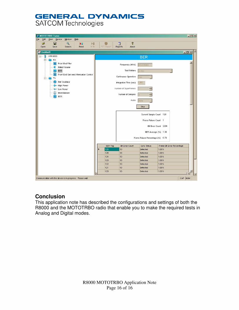
Bit Error Rate (BER) Tests TX BER Test TX BER tests require a PC running the Motorola Tuner software and that the radio be connected to the USB port of the computer through the programming and control cable supplied with the radio. Radios must have version R01.06.00 firmware or above for this test. To check the radio’s firmware version press “Menu” “Utilities” “Radio Info” “Firmware Version”.
• With the power off, connect the MOTOTRBO radio to PC’s USB port using the supplied control cable.
• On the PC “Start” the Tuner software, then turn the radio power on. • Press the “Read” icon on the software control panel. The radio will go into
test mode and download its information to the PC. • Under “TX” select BER. • In the “Frequency” display field enter the channel frequency to be tested. • Select “O.153” in the “Test Pattern” field. • On the R8000 in the “Generate” mode select numeric key ”2” to enter the
DMR TX test menu. • Press “BER Test” followed by “Start” • On the Motorola Tuner control panel press “PTT Toggle” • On the R8000 observe the incrementing “Synchronizations” counter and
ensure that the BER% display is reading 0.00000%.

R8000 MOTOTRBO Application Note Page 12 of 16

R8000 MOTOTRBO Application Note Page 13 of 16
Digital Receiver Tests • Press the blue “Generate” hard key. • Press the blue “Test” hard key. • Select “Test Mode”. • Select “DMR”. • Select numeric shortcut key “1” to enter the “RF Zone”. • Select “Generate Frequency” and using the numeric keypad enter the
frequency of the channel to be tested, for example: 403.025000 MHz. • Select “Output Level” and using the numeric keypad or Spin Knob enter
the desired RF output power. -50dBm is a good place to start. • Select “Gen Port”, set “RF In/Out” using the Spin Knob. • Select shortcut key “2” to enter the “DMR” zone. • Select “Color Code”, set according to the channel to be tested.
Note: if unknown, use “Monitor” mode to read it from a radio transmission then select “Copy CC to Generator”.
• Select “Modulation Mode”, set to “Continuous” • Select ”Test Pattern”, set to “1031 Hz Tone” • Turn on the radio and set to the Digital channel • You should now hear the 1031Hz digital test tone in the radio’s speaker. • Select shortcut key “1” to enter the “RF Zone”. • Select “Output Level”. • It is possible to get a very good approximation of the digital receiver’s
sensitivity by reducing the RF level using the Spin Knob until you hear the tone deteriorate or cut off. This normally occurs around -122 to -125 dBm if you slowly approach the lower level in 1dB steps. This compares well with the -121dBm 12dB SINAD sensitivity achieved in Analog Mode.

R8000 MOTOTRBO Application Note Page 14 of 16
Preset Save Procedure:
• Press the blue “Test” hard key. • Select “Save Configuration As”. • Using the Alpha Numeric keypad and Spin Knob enter a file name that will
identify this test to you at a later date. Example “DMR DIG RX”. • Press the Enter key. This configuration will have populated into the list of
available “Presets”. RX BER Sensitivity Test RX BER Sensitivity tests require a PC running the Motorola Tuner software and that the radio be connected to the USB port of the computer through the programming and control cable supplied with the radio. Radios must have version R01.06.00 firmware or above for this test. To check the radio’s firmware version press “Menu” “Utilities” “Radio Info” “Firmware Version”.
• With the power off, connect the MOTOTRBO radio to PC’s USB port using the supplied control cable.
• On the PC “Start” the Tuner software, then turn the radio power on. • Press the “Read” icon on the software control panel. The radio will go into
test mode and download its information to the PC. • Under “RX” select BER. • In the “Frequency” display field enter the channel frequency to be tested.
R8000 MOTOTRBO Application Note Page 15 of 16
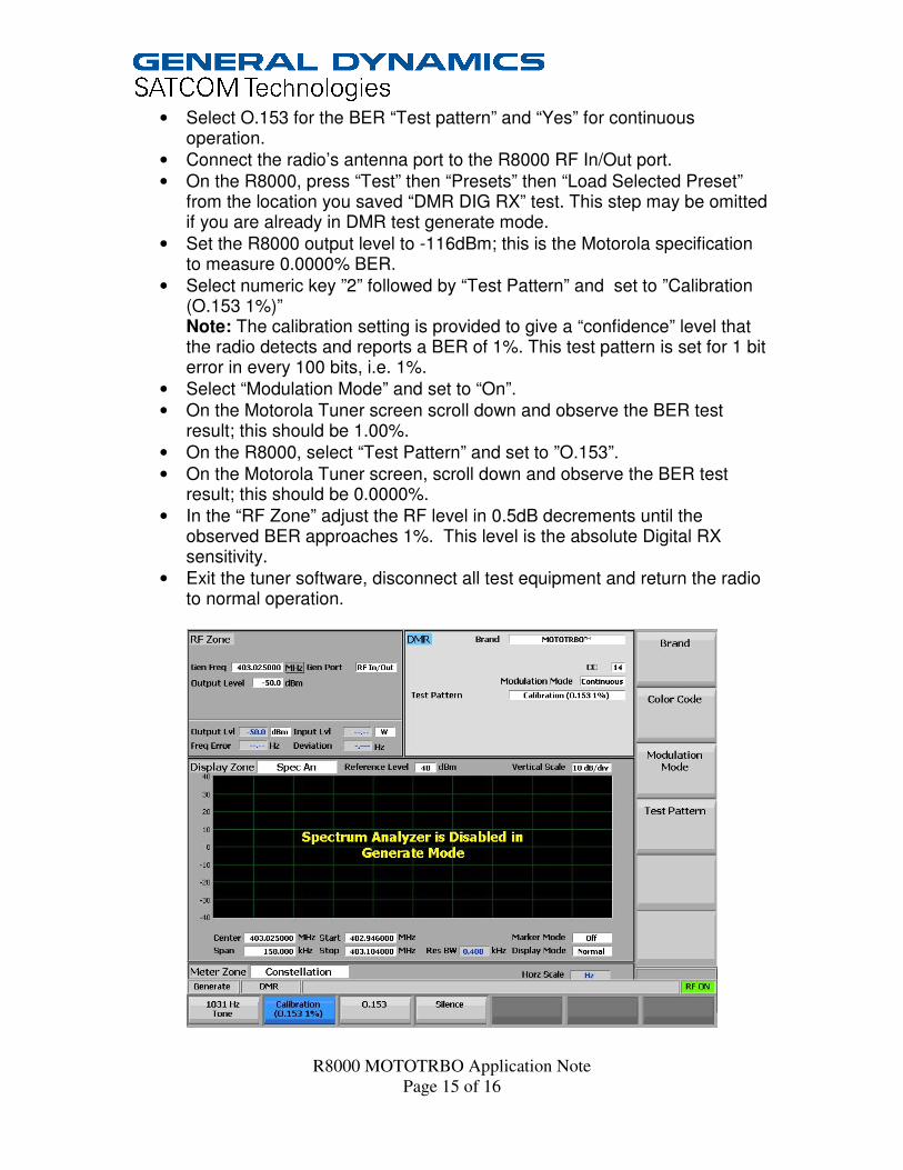
• Select O.153 for the BER “Test pattern” and “Yes” for continuous operation.
• Connect the radio’s antenna port to the R8000 RF In/Out port. • On the R8000, press “Test” then “Presets” then “Load Selected Preset”
from the location you saved “DMR DIG RX” test. This step may be omitted if you are already in DMR test generate mode.
• Set the R8000 output level to -116dBm; this is the Motorola specification to measure 0.0000% BER.
• Select numeric key ”2” followed by “Test Pattern” and set to ”Calibration (O.153 1%)” Note: The calibration setting is provided to give a “confidence” level that the radio detects and reports a BER of 1%. This test pattern is set for 1 bit error in every 100 bits, i.e. 1%.
• Select “Modulation Mode” and set to “On”. • On the Motorola Tuner screen scroll down and observe the BER test
result; this should be 1.00%. • On the R8000, select “Test Pattern” and set to ”O.153”. • On the Motorola Tuner screen, scroll down and observe the BER test
result; this should be 0.0000%. • In the “RF Zone” adjust the RF level in 0.5dB decrements until the
observed BER approaches 1%. This level is the absolute Digital RX sensitivity.
• Exit the tuner software, disconnect all test equipment and return the radio to normal operation.
R8000 MOTOTRBO Application Note Page 16 of 16
Conclusion This application note has described the configurations and settings of both the R8000 and the MOTOTRBO radio that enable you to make the required tests in Analog and Digital modes.