search.jsp?r=19900015866 2018-06-14t18:46:23+00:00z · effect of rocket thrust on a precessing...
TRANSCRIPT

University of California, Los AngelesMechanical, Aerospace and Nuclear Engineering Department
LABORATORY SIMULATION OF THEEFFECT OF ROCKET THRUST ONA PRECESSING SPACE VEHICLE
FINAL REPORT
Participating Students:
Oscar AlvarezHenry BausleySam Cohen
Miguel Falcon-MartinGary Furumoto, Report EditorAsikin HorioDavid LevittAmy Walsh
Instructor:
R. X. Meyer, Adjunct Professor
Sponsored by NASA/USRA
(NASA-CR-186bPl) LABORATORY SIHULATI_N CFTHE EFFFCT OF KOCKET THRUST ON A PRFCESSINGSPACE VEHICLE Fin3l Report (CaliforniaUniv.) lib p CSCL 2IH
May 22,1990
Nqo-z_ISZ
c_lZOUnc|a5028q178
https://ntrs.nasa.gov/search.jsp?R=19900015866 2018-07-26T17:48:55+00:00Z

Abstract
Ground tests of solid propellant rocket motors have shown that metal-containing
propellantsproduce variousamounts of slag(primarilyaluminum oxide)which istrapped in the motor case, causing a loss of specifiC impulse. Although not yetdefinitely established, the presence of a liquid pool of slag also may contribute tonutational instabilities that have been observed with certain spin-stabilized, upper-
stage vehicles. Because of the rocket's axial acceleration-absent in the ground tests-estimates of in-flight slag mass have been very uncertain. Yet such estimates areneeded to determine the magnitude of the control authority of the systems requiredfor eliminating the instability. A test rig with an eccentrically mountedhemispherical bowl was designed and built which incorporates a ,follower" forcethat properly aligns the thrust vector along the axis of spin. A, program thatcomputes the motion of a point mass in the spinning and precessing bowl waswritten. Using various RPMs, friction factors, and initial starting conditions, plotswere generated showing the trace of the point mass around the inside of the fueltank. The apparatus will be used extensively during the 1990-1991 academic yearand incorporate future design features such as a variable nutation angle and a filmheight measuring instrument. Data obtained on the nutational instabilitycharacteristics will be used to determine order of magnitude estimates of control
authority needed to minimize the sloshing effect.
Introduction
Many rocket motor solid propellants in current use contain a significant amount ofaluminum which, when burned, produces a slag consisting of aluminum oxide andelemental aluminum. Most of this material is expelled throughout the rocketmotor nozzle and adds to the thrust, but some remains trapped in the motor case.
The melting point of the (z-form of AI20 3 is about 2050°C, below the temperature of
the combustion gas. The liquid slag, in the form of small droplets, is subject to acombination of forces that include the drag from the combustion gas, the inertialforce resulting from the axial acceleration of the rocket, and (for spin-stabilizedvehicles) the centrifugal force resulting from the vehicle spin.
The present analysis postulates that, because of the high level of turbulence in themotor, slag droplets entering the gas stream are ejected, and that trapped slag isformed primarily by liquid slag flowing along the surfaces toward the point ofminimum potential energy in the accelerating and spinning motor. Also, thepresent analysis concludes that slag will accumulate to some degree in all spinningor accelerating rocket motors with aluminum-contaning propellants and submergednozzles.
PRECEDING PAGE BLANK NOT FILMED
2

A number of spin-stabiifTed vehicles that use aluminized propellant have shown amarked tendency for a "coning" instability; i.e., a precession with steadily increasingnutation angle. These motors have a submerged nozzle geometry, resulting in adownstream annular pocket which is likely to favor slag retention. It has beensurmised, therefore, that the sloshing motion of a liquid slag pool may be acontributing cause of the observed flight instability. The effects of liquid slag on thestability of spinning vehicles is similar to the effects produced by fuel slosh inspacecraft. Slag retention also requires examination because of its potentially
deleterious effect on specific impulse.
Through installation of witness plates downstream of the nozzle, where some of the(now solid) slag particles are deposited, estimates of the size distribution and totalmass of the expelled particles have been made. Ground tests of this type, however,
take no account of the processing of the droplets in the nozzle.
This report consists of a mechanical design that simulates the motion of a spherical
fuel tank in a thrusting spacecraft. A true simulation of the thrust was thought to be
impossible due to the gravitational support forces present in the laboratory.However, through the means of an eccentrically mounted spacecraft model on thetop of a turntable, the simulation of thrust aligned with the vehicle axis is possible.The mechanical design was finished during the 1990 winter quarter and the test rigwas built in the spring. The comparison of the initial description (see figure 1) withthe design actually built (see figure 2) shows the evolution of the design concept.Qualitative analysis will be provided by photographs of fluid profiles at given time
intervals and quantitative analysis by correlation of film thickness from capacitancemeasurements between two platinum wires located in the bowl. This sensor will bedesigned, built, and incorporated into the test rig slip-ring assembly during the 1990-1990 academic year. From these data, nutational instability characteristics and order
of magnitude estimates of control authority needed to eliminate the instability willbe determined.
A computer program was written to simulate the shape of a fluid in a spinning and
precessing container with a nutation angle equal to zero. The fluid was assumed to
be in hydrostatic equilibrium. The fluid depth as a function of position along with
the shoreline of the fluid was determined. A more general code was written which
computes the motion of a point mass in a spinning and precessing hemispherical
container. Using various RPMs and friction factors, plots were generated to
compare the motion of the point mass and validate the theoretical model (see
figure 4).
3

W2
SLIPRING
SHAFT12
11
LEADPLATES
'FOLLOWERFORCE"T
4 3 c;U
BRUSHASSEMBLY
1 BEARING"'ASSEMBLY
SLIPRING
2
MOTOR_t00 RP
AC
1. generalbearing assembly2. AC motor (variable rpm)3. pulleyfor motor shaft4. main drive pulley5. secondary pulley (stationary)6. main shaft7. control arm
8. bowl pulley9. bowl bearing housing assembly
10. bowl mounting flange11. hemispherical bowl (lucite)12. bowl suport shaft13. idler guide
Figure 1: Appratus Diagram (Not to scale)
4

ORIGINAL PAGE ISOF POOR QUALITY
Figure 2: Completed Test Rig(a) top view showing liquid sloshing in bowl(b) front view showing dual motor assembly
5

Viscous Dissipation:
The degree of instability of a thrusting, spin stabilized spacecraft depends strongly on
the amount of internal energy dissipation. The dominant energy dissipationmechanism is thought to be caused by the sloshing of liquid slag at the bottom of thesolid motor casing which directly influences the body's motion. Oscillatory, andsometimes violent, motion of the fluid induce corresponding oscillations of the
body. Viscous effects in the fluid also influence the body causing the nutation angleto change thereby affecting the stability. It is, therefore, important to estimate the
energy losses in the fluid.
Once these energy losses are estimated, one can predict the body motion by reducing
its kinetic energy at the same rate. _ approach is known as the "energy sink"procedure. Due to the growing nutation angle from energy dissipation, thrustcorrections need to be fired to stabilize the craft. This requires more fuel to beincluded for stabilization during launch which ultimately increases launch mass.
Having to fire these correcting thrusters at the right time creates yet another
problem in the attitude dynamics and control of the spacecraft. IdeaLly, nutationalinstability characteristics and order of magnitude estimates of control authorityneeded to eliminate the instability would allow designers to provide the lightest
control system necessary to minimize this phenomenon.
Scale Model Principles
Many different'models have been developed to test sloshing and its effect onspacecraft. Most of these models, however, are made to simulate the sloshing of a
spacecraft in which thrust is absent. One of the recent problems is that an instabilityevidenced by a growing nutation angle has been observed during the firing of liquid
and solid perigee and apogee motors. A new model to simulate this motion wasneeded which properly aligns the "thrust" vector with the model axis.
A simple design of a spacecraft model mounted eccentrically on a turntable can be
used. This rig simulates the thrust as a "follower" force (see figure 3). Previousmodels were subjected to gravity forces acting at the center of mass. But the newmodel produces a resultant of gravity and inertial forces that remains aligned at alltimes with the vehicle axis. Hence, this thrust "follows" the model as is spins and
precesses around on the turntable.
6

z axis
marble
pointmass
"follower"force
R = turntable radius
= angula_velocity
g = 8rarity
(_2 R = centrffugaJ acceleration
Figure 3: "Follow Force Diagram"
0.15
10 Second Marble Trace40 RPM, friction factor = 0.5
0.10-
0.05"
E 0.00
-0.05-
-0.10-nutation angle = 15 deg rim at R = 0.15 m
I I tI l l
-0.15 -0.10 -0.05 -0.00 0.05 0.10 0.15
x [m]
Figure 4: Computer Code Results
0.20
Because of space and cost constraints, it is necessary to have a model that is not full
scale. It must then be shown that the model behaves in the same way as the
spacecraft. Therefore, it is required for the model to have the same inertia ratio asthe spacecraft:.
odel pacecraft
It also follows that the ratio of the precession rate to the spin rate be the same inboth the model and the full scale model. To simulate the dynamics of the sloshingrequires that the Froude numbers of the model and spacecraft be the same:
Froude number"Ri(d(_/dt) 2"
5
g/cosO model
[.Rt(d_/dt)_
= [ TIM
Solving for (dO/dr)model:
(d_/dt)mode 1 = (d(_/dt) s ._pacecraft '_ (Rt)modelTCosO o
Using these equations, a good approximation to a thrusting spacecraft can be madein the laboratory.
Mechanical Design:
A distinct design evolution was experienced in attempting to construct a test rig
which would adequately simulate the conditions present during the burn of a solidpropellant rocket motor. As a preliminary experiment it was primarily designed toprovide a qualitative analysis of fuel and slag sloshing and aid in the development
of future experimentation.
The design problem was to simulate rotation about the rocket's own axis and the
subsequent precession about an associated axis, both of which are effects of spin
stabilization. It was initially agreed that dual rotating shafts were best fitted to
produce the kinematics of the situation, and subsequently the design problem waslimited to developing a system that would drive the two shafts with correctdirection and rates of spin. In order to achieve this effect several proposals weremade, first of which entailed using a set of belts and pulleys driven by a single
electric motor. Succeeding designs included such elements as a planetary gearsystem, a set of rubber wheels, or a set of dual motors. In the end, the initial conceptof belts and pulleys was adopted for their availability and ease of use.
8

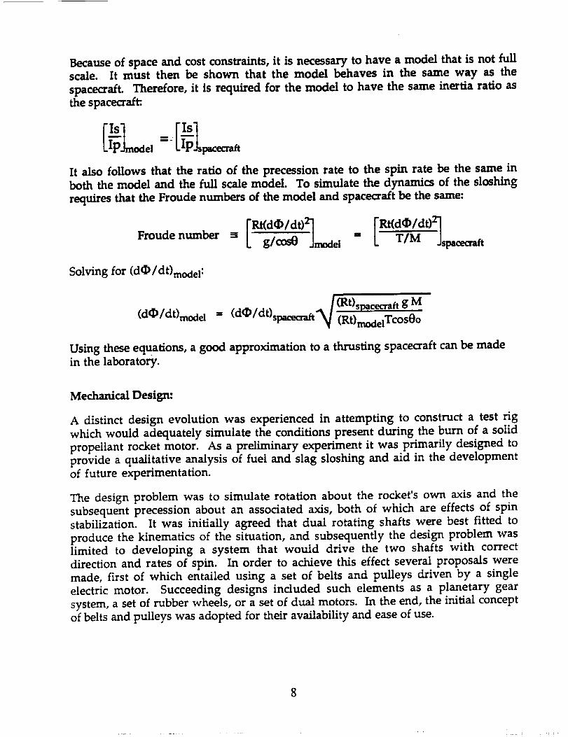
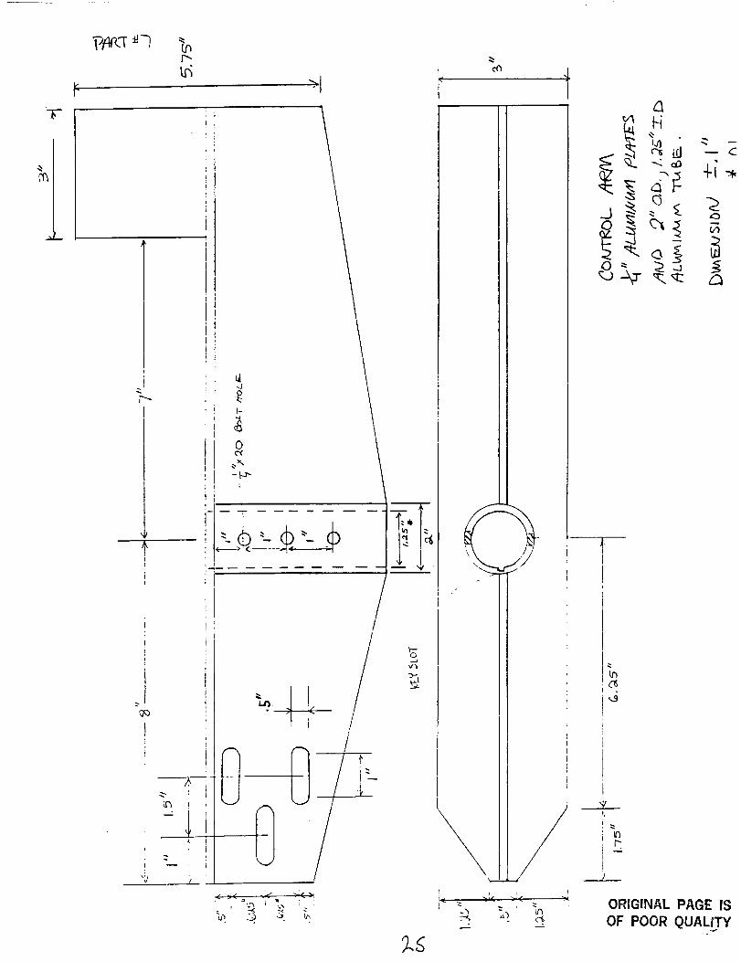
The rig is mounted on a half inch thick aluminum table, approximately one metersquare and held up by four nine inch long aluminum legs. The main shaft ispositioned verticallythrough the middle of the table,housed by a bearingassemblywhich is mounted to the under face of the table. This shaft is driven by a belt,
connected to a variable RPM electricmotor also mounted from beneath the table.
To the top of the main shaft is mounted a control arm made from an aluminum Tbeam. On one side of the control arm isthe fuel tank assembly and on the other,an
equal counter weight made of lead plates.
The hemispherical bowl, turned from a Lucite block, is mounted to a second shaftwhich rotateswithin the bearing housing mounted to the control arm. P6sitioned
on the main shaft and on the bottom of the second shaftare two pulleys. 'ITmpulley
on the main shaft is secured and remains stationary with respect to the table. The
other pulley is secured to the second shaft and produces the rotation of the bowlabout itsown axis. A crossing belt connects the two pulleys,and as the main shaft
rotatesat an average rate of forty RPM, the second shaft rotatestwice as fastin the
opposite direction. In order to keep an adequate tension in the belt,the bearing
assembly housing the shaft,can shifthorizontallyby ± 0.5 inch. In addition,an idler
isincluded on the controlarm to guide the beltand maintain itstension.
During the next academic year (1990-1991) a sensor will be designed which
determines the film thickness by measuring the capacitance between two platinum
wires. This will hopefully provide a means to quantify the force and momentum
produced by the rotatingHquid in the bowl atvarious RPMs. In order to incorporatethisinstrument, an electricconnection to the bowl is needed through a set of slip
rings in the rotating mechanism. Just below the bowl and above the bearing
assembly ismounted the firstslipring. And at the bottom of the main shaft below
the bearing assembly is mounted the second slip ring. To connect the wires from
the controlarm to the second ring,a hole is drilleddown the center and through the
entirelength of the shaft. Through thishole the wires are run to the slipring.
Computer Stmulafiom
A theoretical analysis which approximates the fluid in the bowl with a point masswas developed. The result was a system of two ordinary differential equationswhich can be solved numerically by Heun's method for initial value problems. A
code was generated which determines the x, y, and z coordinates of a "marble"rolling around inside the bowl given a friction factor, initial starting coordinates,bowl RPM, and nutation angle. The friction factor was varied to simulate the effectsof fluid viscosity and friction of the point mass. The larger the friction value, themore of a damping effect the marble exhibited. For smaller values, the marble took
longer to stabilize and rose higher in the bowl (see figures). When the actualexperiments begin this fall, the code can be properly validated with better estimatesof the friction factor, RPM, and nutation angles necessary to demonstrate a valid
theoretical model and test rig.

ORIGINAL PAGE IS
OF POOR QUALITY

TABLE OF CONTE_,FI'S
INTRODUCTI ON ............................................... I
LIST OF SYMBOLS ............................................
REFERENCE FRAMES ........................................... H
STABILIZATION PRINCIPLES ................................... _"
$SCALE MODEL PRINCIPLES .....................................
MECHANICAL DESIGN .......................................... 13
DESIGN SKETCHES ............................................ 16
COMPUTER ANALYSES - A. :SIMULATION OF --LUID SHAPE ........... _"
B. SIMULATION OF POINT MASS MOTI ON .... ./_,
HOT TUNGSTEN WIRE ANALYSIS ................................. /_'_
LIST 0F MATERIALS .......................................... _I
CONCLUS ION ................................................. _
PRELIMINARY DESIGN ............................. _"
CALCULATION FO FLUID ,SHAPE SIMULATION .......... _:_
POINT :_ASS MOTION HANDOUT ...................... g0
POINT ....IASS HOTION COMPUTER PROGRAM L:STING ..... _"-
UELOCITY CALCULATIONS FOR H0T tI!RE ............. G_
REFERENCES ................................................. lOS""
SIBLI 0GRAPHY ............................................... / 0_)
APPENDIX A:
APPENDIX B:
_mFENDI}," C:
_RPENDIX D:
APPENDIX E:

INTRODUCTION
ORIGINAL PAGE ISOF POOR QUALITY
In
permit any energy dissipation.
all spacecraft and rockets
including elastic structural
motion of fuel
Since Explorer I,
theory, the definition of a rigid body does not
However, it is known that
have some non-rigid entities
deflection and the liquid
n its tanks, otherwise known as slosh.
t has been known that these properties
can have a major effect on the motion, that is, there can be
instabilities that depend _argely on the internal energy
dissipation. In most spinning spacecraft and rockets, the
largest amount of energy dissipation comes from the liquid
s Iosh.
This report consists _f _ mec-_- r, ca_ _es.gn that
simulates the motion of a spherical fuel tank, in a thrusting
spacecraft. A true simulation of the thrust _4as t_,ought to
_e _mpossible ,_ue to the gr_vitaional support _orces _resent
n the ' abor atory. However,
eccentr i,=al ! ;," mounted spacecraft
turntable, i t _Jas discovered
through "he means
model :n the
in reference ! ,
-f &n
-_imu!atic, n ,_-,_ thrust &l igne._ ,Ji th the ,ehi,-!e
noeec _ossib!_. The mechanical design is -_=cheou'.eo to be
{n -he "orm _f pictures and -_ata c_llected ._=,bout the depth
of _Jater __t -ertain points. The re=_ul ts tJill then be
:ua] i tat ,,,el::_ presented .;Ji th .=onclusions drawn ._oout the
; I ,_n i r _ _.-r _.';e ,Je i . r-I _,aci,,,._roun_ ,:n :7";e ;zes i :_F_ B.r_O & ] St
:f mater :-]s r eedeo _;r t_:e _o_=ign &re nc!_=e_,
too _f a
-hat the
_XJS _Ja$

Also presented in this report is a theory on the
possibility of using a heated tungsten wire to measure the
depth of liquid in the model. By relating the heat loss of
the wire to the depth of fluid inside the cup, it _Jas
thought that an accurate reading of the depth could be
obtained. However, after many calculations it _Jas found
that there were too many uncertainties for the hot wire to
be an accurate device. Nevertheless, these calculations are
valuable and therefore included.
A computer program _,_as _vritten to simulate the shape of
a fluid n a spinning ancl precessing container v,Jith a
nutation angle equal to zero. The fluid was assumed to be
in hydrostatic equilibrium. The fluid depth as a function
of posi tion _Iong ,,vith the shorel ine :_f the _luid _ere
determined. A program that determined the motion -.f a point
_ass in a spinning and precessing hemispherical container
,,,,.as ._.Iso _,,_ri tten. L_si ng different condi t ions, , .e. ,
different RPrMs and friction f__.ctors, plots were generated to
.-_ompsre the motions of the point mass.
oRIGllxlAt- PAGE IS
OF pOOR QUALITY

LIST OF SYMBOLS
(X,Y,Z)
(x,×,z)
0
M
m
r
Og
I
T
_e
h
D
_r
_..lu
Inertial reference _rame
Body-fixed frame
Precession rate
Spin rate
Nutation angle
Total mass including fuel
Fluid mass
Kinematic ,Jiscositi_
Radius
Centripetal .acceleration
Density
Acceleration of gravity
Moment of inertia
Thrust
Reyno!ds number
_roude number
Per_i nine to smacecrsEt
Pertsning to model
Height
Oressure
Angular .Jeloci ty _subscr i_s c_v_cus)
Prandt! number
_3r _o_ _umber
Nusselt number
3
ORIGINAL PAGE IS
OF POOR QUALITY

£zx
_.oo
Z
×
ORIGINAL PAGE IS
OF POOR QUALITY
q "3,, _f

STABILIZATION PRINCIPLES
There are primarily two
techniques currently in use. They
and three-axis stabilization,
advantages and disadvantages. Since
rockets and thrusting spacecraft, we
in spin stabilization.
Spin stabilization is based on the
produced due to the rotation of the
Dual-spin, which involves %_o types _f
precessing :f the
technique as opposed
rockets carry much
the motion of
the presence of
_rom itS _omir_&l
_iosning" .
--_ e
strong_i cn =_e
most _ominant
sloshing vJhich
different
ape
each
we are
will be
stabilization
spin .stabilization
of which has its
concerned with
most interested
rocket is the
to single-spin.
of their fuel
this fuel ,due to
thrust is of
position s
the
g r e ._t
_..vh a t
gyroscopic stiffness
rocket or spacecraft.
sp inn ing _nd al so
most common stabi! izaion
Since spacecraft and
in the form of a liquid,
spin stabilization and
interest. This motion
,s _:nown _s "! iquid
.smour. t -_ -_tern.._l ener_>' ,dissipat;,.-_,n, The
energy dissipation rr,ech&n i sm ;s the fuel
influences the boO>'"s moticn immediate]>" and
=ir-ect]/. OSCi _ '._.tor.>', _.nc; .-_ometimes ....._¢.,ient, motion of the
_l,Jid ncluce :orre-=.ponding
"i=cous.,_ e_c_:s..._ _n. the Z_uic_,
osci_',ations of the body.
also influence the body .:.._using
thereby &ffecting the
:moor. rant to est {rr.;,._tethe
the nutat i on .:-,ng! e to ,:ha.nge
_herefor-_sta.bi! ; t:/. "t , sj .
•: r_ e r "_ 7 : 5 _. -=
5ORIGINAL PAGE IS
OF POOR QUALITY

i
The ener'gy dissipation r.s. te ',s assumed to be ._. ;'Jnction
of the many spacecraft parameters as follows,
where,
M = total mass including fuel
m = fluid mass
= kinematic viscosity
R = radial distance of tank center from spin axis
r_ = radius of tank
r4 = radius to free __urfa.ce
a = centripetal acceleration, r ,." _ )
etc.
expanding in an infinite series representation,
_:Jher._ ei_ = exponents, --- !,2,, , ,!2,. i = !.,2 ....
Using the non-dimensional ization process using the
"Buc_:ingham P! Theorem" ':see reference 2) __.nct >Jriting the
,.esu;t in the original form ,.'_gher.e terms of like exponent=_.
have been _.r.ought together ind the exponents droppe,_),
some cf these terms can be " rzvertecl to =.how their more
= Reynolds number
= Frou_e r, urnber
= _:r ic:!cr_ ._i: "
ORIGINAL PAGE IS
OF POOR QUALITY
-)?,

Once these energy _osses are estimated, one can then
predict the body motion by reducing its Kinetic energy at
the same rate. This approach known as the "energy sink"
procedure is beyond the scope of the class. A more _etailed
discussion of it and energy dissipation can be found in
reference 3 and reference 4.
One of the results of this growing nutation angle from
energy dissipation is that c,orrecting thrusts will have to
be fired to restabilize
_uel and _horten the
these correcting _rusts
inother _ro=!em ;n the
The simplicity of spin
sloshing will still remain
the craft. This will use up more
life of the craft. Having to fire
__t the right time creates :/et
stabilization means that :iquid
a c.hallenging problem.
-7
ORIGINAL PAGe' IS
OF POOR QUALITY

SCALE MODEL PRINCIPLES
Many different models have been developed to test
sloshing and its effect on spacecraft. Most of these
models, however, are made to simulate the sloshing of a
spacecraft in which thrust is absent. One of the recent
problems is that an instability evidenced by a growing
nutation
liquid perigee
Therefore, a
founO.
angle has been
and apogee
new model
observed during the firing of
rocket motors (reference I).
to simulate the motion had to be
As seen _n reference I, an intricate model need not be
made. Instead, a rather simple design of a spacecraft model
mounted eccentrically on a turntable can be used. This rig
simulates the thrust as a "follower force" (figure I). As
opposed to figure 2, where the model is subject to gravity
r-eact!ng force_ acting at its center =f mass, _igure 3 shows
the _esign _here the model i ies eccen_r icai l>- on a
turntable. This _ro_uces _ resultant of _ravi ty and
inertfal _orces that remains aligned it il! times _Jith the
vehicle ixis. Hence, this thrust is of the type _e_erred to
_S a "zol _ ower Zorce "
Because cf space _.no cost :snstrlznts, i t is necessary
to h._ve i model that is not full _cale. :t must then be
shown that the _o_el behaves in the same .va>" is the
spacecraft. ?herefore, it is required for _he model to have
the ._ame _nert!_ ratio as the _Dacecra÷t,
ORIGINAL PAGE IS
OF POOR QUALITY' I

!t also fol lows that the ratio of the precession r_te to the
spin
mode I .
that
rate De the same in both the moc_el and the full scale
To simulate the dynamics of the sloshing requires
the Froucle numbers of the model and spacecraft be the
same
Fr-om this Jt is seen that
| J ' _ ' ' I
Using these equations, a true simulationof s thrusting
spacecreaft _an be made.
ORIGINAL PAGE IS
OF POOR QUALITY

000
1:_:[
__ °
2
Z
/
L
, (f-_
J
0 :- IS, O°
lbORIGINAL PAGE ISOF POOR QUALITY

/fi
/
ORIGINAL PAGE IS
OF POOR QUALITY

RI#E
/(2O7" "_ Sr.._.
I
7
fl
RI
iI
,{tour ICCKF,{IA<..
17.-
OR1GINAL PAGE ISOF POOR QUALITY

MECHANICAL DESIGN
A distinct design evolution was experienced in attempting to
construct a test rig_ which would adequately simulate the
conditions present during the burn of a liquid propellant rocket
engine. As a preliminary experiment it was primarily designed to
provide a qualitative analysis of fuel sloshing and aid in the
development of future experimentation.
The design problem was to simulate rotation about the rocket_
own axis and the subsequent precession about an associated axis,
both of which are effects of spin stabilation. It was initially
agreed that dual rotating shafts were best fitted to produce the
kinematics of the situation, and subsequently the design problem
was limit_l to developing a system that would drive the two
shafts with correct direction and rates of spin. In order to
achieve this effect several proposals were made, first of which
entailed using a set of belts and pulleys driven by a single
electric motor. Succeeding designs included such elements as a
planetary gear system, a set of rubber wheels, or a set of dual
motors. In the end, the initial concept of belts and pulleys was
adopted for their availability and ease of use. The details of
test rig's design are the following:
The rig is mounted on a half inch thick aluminum table,
approximately one meter square and held up by four nine inch long
aluminum legs. The main shaft is positioned vertically through
the middle of the table, housed by a bearing assembly which is
mounted to the under face of the table. This shaft is driven by

• m
a belt, connected to a variable RPM electric motor also mounted
from beneath the table. To the top of the main shaft is mounted a
control arm made from an aluminum T beam. On one side of the
control arm is the fuel tank assembly and on the other, an equal
counter weight made of lead plates.
The hemispherical fuel tank, turned from a lucite block, is
mounted to a second shaft which rotates within the bearing
housing mounted to the control arm. Positioned on the main shaft
and on the bottom of the second shaft are two pulleys. The pulley
on the main shaft is secured and remains stationary with respect
to the table. The other pulley is secured to the second shaft and
produces the rotation of the fuel tank about its own axis. A
crossing belt connects the two pulleys, and as the main shaft
rotates at an average rate of forty RPM, the second shaft rotates
twice as fast in the opposite direction. In order to keep an
adequate tension in the belt, the bearing assembly housing the
shaft, can shift horizontall_ by + or - half an inch. In addition,
an idler is included on the contol arm to guide the belt and
maintain its tension.
If a feasible means of determini_the depth of the fluid could
be produced, an electric c0_ce_ction to the fuel tank would be
necessary. For this purpose, incorporated into the design is a
set of slip rings to make possible electric connections to the
rotating mechdnisms. Just below the fuel tank and above the
bearing assembly is mounted the first slip ring. And at the
bottom of the main shaft below the bearing assembly is mounted
the second slip ring. To connect the wires from the control arm

to the second ring, a hole is drilled down the center and through
the entire length of the shaft. Through this hole the wires are
run to the slip ring.
The following are detailed drawings of the individual parts.

eLI
I"--
!
i
J
/r
!
i
I
l
/
!
//
-.I
\\
(i)
/
De_id n 5 k_-foh_
a.[_0
©
-t.
c%
8
,,o "_'t
J

._
©
_J
©r_°rm_
a_
c_
°_,._
c_
C_
O
oiQ_

pA P,,T-e 1
'--0,,,o",
I
II
I
I
I
L
-F.5"00 _
ii
.500
J_ i
T 1
mAIN BEARIN6TV_ _Ro_ _LOt4_Nd_4
SToc_ CVL.,_IO_K..
DI_'N_'I0_ _ :I: 0,010 _
HOU&eA& Fe£ o_iE
&6aL_D 0£_P_65
I'/_" I.D
z'/_" o,_Ii,.i, vl/l_T_
! -'T t "_*-
2__.2__ JI_--- + .001
I - ,oo0
_J L ,
J _ "J2_:Iti .oo_
/-- /LxZO
3/4 n ,3=.PT'N
_i rff T_O
ORIGINAL PAGE IS
OF POOR QUALITY
SCALE 1"2

c_ c_°_,_
c)0 "-_
° _ _
_ E
tu_
c_C_
Q_
QJ _
QJ _
c_
C_
0
0
......._" 'i!!
r_
C_J
J_

¢)
r_/"j
p.
0
0
0
I
+
0. _,,,.,,,_
O"J
¢)
,--, d
........ iiii1
0
T
l

\
/r
f
\\
_ j/
sT_u_4_ k_EV
I" i
' t
Ii
<
I
I
1Ii
1
i
II II
I
:,It
li_ KEy _LOT
>i
ORiGiNAL PAGE IS
OF POOR QUALITY
c_.yL!/JOE(_,- E"_,
%1

_-r-_
/
I
II
0 I _" "_._.
£'_" 0._.
_. " bdtl_14
- ORIGINAL PAGE IS
" OF POOR QUALITY <L./iJ
)£, ,1 I 11 I I
_L_D ALL_J,JCAP Scf, EW
/
/
12_
sEco _8 a_.VPuL_..V
,i,. ,,,J

PART_ 6
E
!I
!
7I'N.' :
_A_ S_AFT
"FO_N_.I) FR_ i._ _j Dj_
I0__0 C,._L_ ROLLED STE_L.
II
S
//;I
q' :: I'_c, 1' !11'
T, _. °
ORIGINAL PAGE ISOF POOR QUALITY
,SCAL_ ;'Z

i_© i ¸.
• .r
Ik. -_"
ORfGtNAL PAGE ISOF POOR Q_JAL1TY
T"
/-,,
---I
t
u_
..<
j_P_
P
ORiGiNAL PAGE IS
OF POOR QUALITY

PART _=8AL.Ut_lJJo_ STOCK
11
I{,
ORIGINAL PAGE IS
OF POOR QUALITY
I1
1
I
I'I
_LoT,:--l-}
lJ
il
L_,Oll
TII
1,0
SCALE ±'_.L.

_qr"
.4.
L
_4
0
oko
V_
V
:......F _-i
/\
!/

1
_L
2.fl

PAP_T# lO
_-I'E£L _TOC&
_ouxJn_16-
TA I_l LE_; S
±0, o10
I2. HOL_ NITH
Lilt
; i _I
iII
-- 2.
i
III
[
I
I
i I
JI
TII
I I J.o
I
ORIGINAL PAGE IS
OF' POOR QUALITY
S_,ALE !:_

c_
c_
olml
x_
°flul
q_
1 ' _i'

17
/
/
r"
ORIGINAL PAGE ISOF POOR QUALITY

PA_T
FuEL "FAJ,]K (.OPPoRT SHAFT"
i_ 2-o _"D RO(.L..6_ _1"_'_L .
ALL l:)a_'tJ_aoAl,_ ± O. OlO _'
lI"
_if"
• 7.5"
t '
I
II L.
i
I
i
t.7S"
t
1 I
35
SCALE _." _.

II
_
fIi
i/' _ j,'
i
@
\ •
.J '
\
____/t tJ
I
1i iI
:N _"r.
tOELD _l UI-
1/
#
zfz__4_wuM __

Simulation of Fluid Shape
In order to gain insight into the instability of a
spacecraft due to liquid slag, a simple study of a liquid
under simulated static forces should be made. This study can
be made by applying Bernoulli's Equation (i) for both
spherical and _rtesian coordinate systems in 3 dimensions.
-(V-P + _-g-V-h) = _-a(I)
If applied properly a shoreline--the line where the
fluid meets the cup--can be graphed to obtain a top view of
the cup. Moreover a cross-section of the front view may also
be obtained. Due to the difficulty that the actual spacecraft
precession poses with its nutation angle, a simplified study
shall be made using a cup without a nutation angle.
Before the detailed study of the fluid shape under
static forces is made, it is useful to conduct a qualitative
examination of the fluid shape. Since the cup is spinning
about its own axis, as well as about a point located at a
fixed distance from the cup's center, one can assume that the
fluid's actual shape is the superposition of the shapes
caused by each motion separately. Figure i shows a picture of
the posed problem while figures 2,3 and _ are purely
qualitative drawings of the fluid_ shape before any
calculations were done.

<
-X
Z
I _ .... jl Ir=up 0 r=u_
< >
r_m
Figure 1.
>
+X
ii
Fig.2 rotation about
the cups center.
!
|
Fig.3 rotation about a
fixed point.
Summing figures 1 and 2 figure 3 is obtained.
• " " r
!I
Fig.3 superposition ofshapes in Fig. 2 and 3.
Now that a qualitative understanding of the situation
$_ Om_rNALPAGEISOF POOR OUALITY

has been made, a theoretical solution should be constructed
using equation (i) applied to our posed problem of fig. I.
Applying Bernoulli's equation in the x direction, eqn.
(I) reduces to eqn. (2):
d
-[p'dx (2)
where: -r=u_ _ x <- r__u_
> acceleration due to the cup's
rotation about a fixed point.
acceleration due to rotation
about the cup's axis.
After integrating and assuming zero gauge pressure
outside of the cup, equation (3) is obtained in the xy-
plane:
W=L,D 2 + Wa.-,. 2 W_,-,,1 2 *r_r-m
z(x) - *x 2 + .x + z(0) (3)
2"g g
Similarly applying eqn. (i) in the y direction, the
following is obtained (%):
d
_[p+ :0a dy \
where a_ is :
ORIGINAL PAGE IS
OF POOR QUALITY
(%)

ay = w_p2-y where: -r_p _< y _ r_p
Note that there is only acceleration due to the cup's
rotation about its own axis in the yz-plane at the instant
time we apply eqn. (I). Following the same integrating
procedure used to obtain equation (3), equation (5) can
easily be shown:
W_up 2
z(y) = .y2 + z(0) (5)
2-g
Combining equations (3) and (5) we get a general three-
dimensional expression for the height of the fluid in
Cartesian and spherical coordinates (6a) & (6b). See appendix
for the definition of spherical coordinates used.
z(x,y) = ...... x 2 + °x +
2"g g
*__ u p 2
+
2-g
•y2 + z(0,0) (6a)
z(R,¢,e) =
W,-up 2 + Wa,-,.2
2"E
•R-cos(¢)cos(8) + w.,-m2"r.,m
"R'cos(¢)cos(@) + z(0,0) (6b)
In the xz-plane (front view, z(x,y=0) ), we obtain a
ORIGINAL PAGE iS
OF POOR QUALITY

o
parabolic equation. By adjusting the constant z(0,0) one can
determine how high the fluid may be at the middle of the cup
before it would spill out. A quantitative plot was made and
the initial height of the fluid determined to be 0.91cm using
MathSofts's MathCad program. The following graph, constructed
for the xz-plane, indicates the qualitative drawing for the
final fluid shape in the xz-plane was indeed correct
r,, iiIII ,¢' I
.- .'"¢ ., ?'
,.*'
" ... "..%",.., ..."
To obtain a shoreline of the fluid (xy-plane,top view)
one must combine the equations for the height of the cup
with the equation obtained for the height of the fluid shape
(6b).
The since the cup is a sphere, the equation of the cup
may be described by equation (7a) or (7b).
ORICINAL PAGE IS
OF FOGR QUALITY

Z2 + X2 + y2 = R2 (7a)
Z = J R 2 - x 2 - y2 (7b)
_Combining equations (7b) and (6b) then letting MathCad
handle the algebra and plotting, we get the following graph.
. .....-'*"--" -'--, ."'°°..
...-"
....-"
,, ...i-'° "-°...o.
., ...
,.' ...,"
°.. ..,.•"
r .,"
Lii*I ,'
I l i'
I!
I!
fill "I',,i
11 "'l.
'". "...... o,_ $ .........."....... lard .......
""... .../
- "-'9_,_.._/ .........-............ ...........
*°.. ",
".. '.%
" %.. _',,
'i II',. I
", ,I
I
,il,,' I
,, I
.,. ,,'•.' ,!
,. !
..'", .,. ,,"
If we examine equation (6a) we see that the form of the
equation for the xy-plane is that of an ellipse displaced
some distance from the origin (8).
A.x z + B.x + C-y 2 = D
or
A'.(x + b)2 + C.yZ = D
where A,A',B,C,D are constants.
ORIGINAL PAGE ISOF POOR QUALITY
(8)
This form of our equation certainly agrees with the plot
of the shoreline performed on MathCad as one can easily see
by inspection. Thus we may conclude that the plot agrees with

the equation obtained for the fluid shape.
One may attempt to dispute the validity of the
equations: however, recall that the problem of the actual fluid
sloshinE was not solved but rather a simplification of the
problem. The solution thouEh is still useful in EaininE
insight to the degree of fluid sloshing under the simulated
conditions that have been chosen.

COMPUTERSIMULATION OF A POINT PIASS
A theoretical analysis representing _ fluid by
displaced mass point has been developed by reference 5.
Using this knowledge to validate our efforts, it was desired
to track the motion of a point mass in a spinning and
precessing hemispherical container with a nutation angle
equal to zero• This was done in reference 6, (see appendix
_), resulting in the following _overning e0uations:
Using Heun's method for -olving ordinary differential
equation=_., as in reference 6, and noting that the q-antities
_, _, and _ _re near!'/ constant: "he posit!_n -_f the F-oin_.
mass _s _ ._,_'nc'.!._n,of time ,.,.J._s_.__unc]• A computer -.rogr_m
,,Jas vJritter, -o gener.__te the _at_ neecled t_ develop -. plot _f
".he mot ions .:see e.ppen_i." C?,.
'Sever_m! nitial conditi_-,ns _,,ere '_=ec_ " •e. _0, 40, end
30 RPMs, -end friction ._ac_rs -_ '°'.50, v.,5, i _0) ano plots
.._ere maoe ;or e.sch ,of the n!ne -onoi t _ons. " t ..._as ;oun,_
that no matter ',_hat valu_ the f_ictic.n _:._ct__r had, the point
,mass _!ew c,ut _f the cup .._.t 'SO RPM. In _ct, _irel>.
differ-ence --..motion v_as ibser.'.,eo .'.:=_ee_!gures "-_;.
However, __.t 40 RPM, the s_z÷ :f the _;cti:zn _ac_or
nf!.-enced the mo_ion in two distir:c*. '.Jays, see =:._ur.es 4-_x,.
ORIGINAL PAGE IS
OF POOR QUALITY!I r

At a lower value, the motion rose higher in the cup as
expected. Also as expected because of the greater motion,
the point mass in the case of lower friction factor took
much longer to stabilize and have a smooth motion.
In the case of spinning at 20 RPM, see figures 7-9,
much less is obvious. Since the spin rate is so low, the
point mass stays much :_ser _o the bottom _f the cup. The
most interesting observation is that again the friction
factor plays a large role in compactness of the motion.
This theoretical analysis, though it is valid, will not
have much of an influence in the report except that it shows
that a stable motion can be achieved. Applying this to our
problem we can hope that an equilibrium of the fluid
motion can be found.
ORfGINAL PAGE IS
OF POOR QUALITY

w_s
_oo
I
-. 15:} i
•i5c3
-. 15¢.')
r_
IIII i
u I,, II
'-. ,,'
t. _°_
,.-"
°.-
"'..
..,
.+
""!
.!
"t
't k
'%°,
o
Ii !'
J
j'
..>'"
..J
.°o"
-. 15el y ,,:'p(':i)
! ........._.-2--i'i--_"---==-'---................
I °.. °°...-
+..
.150
' r,. .- .
i Ii_ _' _
t • _ __ 11_ _'_._
_ "-_ iII_
_" .>__.I .°"'
I
II
i f
., .,'"
'g .,.,. ...***'-
1
|Oi,"_"t
'%5 "
"1
'" I,,.'
"...
t "1..°.. .°" "*""
_'°. i-°.. .° _.--'°
-. 150 y ,yp<¢) .15¢')
•150
-. i5¢-_till
ORIGINAL PAGE IS
OF POOR QUALITY

wtme,44,1
z_
ooooc
e
J
-. 150
• 15:}
-. 151:)
•150
k
,.,
iqI
°l
*%
-°.,
m --o.
-_'_ .._.,.
°-%
,. ,.,,.-..,. ._.........,
. I_ '.-t....",,,;.......,"'--.,
"-........,:i,. _t'-........._",j ....,';._, J '.__--'".-; ,_..- "--_. ,". ,' _'_'....... :;" "1", ,'....
-___f__.....,:....,,:_.......__._.......,
-. 150
..,-"
/v"
.r
,l':
-, 150
,/¢
iI!
"'.,
%.
"Io
'i
.71!lit
.,-
°.../
.o.-°
""---""?:---- ----_*_.--Z'-"
°o,.
..." ."_."._:,
....._-_-_-.i _", ':,
iI" _i
!__
..=. ,¢""
. _.,_,.....
•-'-- i
,J
'I
%
%
,_o'
.,"
../
"o,
"'--...
°'-.°
°--. o--__ __
"".%.,
"...
•150
j"
.,. ,''
. ,._"
.o.,-"
._..-°
Y _YP((]) .150
• ZL-- ..........
,.o" ",,.
",,
'-*,
"i
7
/'
l
....'
../
o.-
ORIGINAL PAGE ISOF POOR QUALITY

_,ww
41'
I
J
>,
1
'-.:
+,+-. ,,.+
No 3
// I
r,A.._, '_':' ._, . ...-{_-_r,..,"'
iI i'I
i I
%1
i o
'+1. ,j
""'% J
+"+. ° .+'+
-,. °o.*"
-. 15(:) y .+yp((!)) . 150
i
r -- ..-'---_ .... "'_'"-.....
, .- -...
..- "'-,..
"%
i /" % %
! ,' ',
a' "l
• i 11
• i_ ;ID • +o,lk,.
,vi'+.+ ;......_
II" iillI2 I
I|i, ,,
%' } i• 2'1
, !
+,.% j+
+'°.o ...o"
+-. .---o. o...
-.15 +.) Y :YP< (')) .i5(:)i
y..+.""
,,+'
,++
i/_ ":
i1'
I+ llll(l I
,j
..-.-"
, .°-"
.:.......?;!+-:,° "+%'"_"i
--°°%
°'°°%°..
...°",..
",...
%
"% t
'nt:1
11,
1iI
?+
I'
+.:'
...+.""
+.,
_..o_. °*"-
ORIGINAL PAGE 18
OF POOR QUALITY
t_-+

HOT WIRE
In the process of designing the experimental fluid
sloshing machine, the question of how to measure the
depth of fluid in the sloshing container turned out to
be a very challenging project. Professor Meyer proposed
the use of a heated tungsten wire inside of the fluid
container (cup). The heat los& b_ the wire would in
turn be related to the depth of fluid inside of the cup.
Other proposals, llke pressure tabs and simple capillary
tubes, were also considered and thoroughly discused.
Since the hot wire proposal seemed to be the most
promising path, several calculations were done to relate
the heat los& o% the tungsten wire to the actual depth
of fluid in the cup.
The hot-wire was intended to be an application of the
Hot-Wire Anemometer commonly used in measuring the speed
of fluids. The hot wire anemometer is basically a
thermal transducer. An electric current is passed
through a fine filament which is exposed to a cross
flow. (This fine wire is actually one of the
resistances in a Wheatstone bridge circuit). As the
flow rate varies, the heat transfer from the wire to the
flowing fluid varies (increases with increasing velocity
and decreases with decreasing velocity). This variation
occurs because the electrical resistivity of the wire is

"Q
a very strong function of temperature. Hence, when the
wire loses heat (it cools) its electric resistivity goes
down (true for metals).
There are basically two techniques to monitor flow
conditions with the hot wire: constant temperature and
constant current flowing through the wire. When the
current in the wire is kept constant, the changes in its
electrical resistivity unbalance the Wheastone Bridge.
This is recorded as a voltage drop across the bridge.
On the other hand, when the temperature of the wire is
kept constant, then a feed-back control will have to be
part of the Wheatstone bridge. This feed-back control
will sense the increase or decrease of heat transferred
by the wire to its surroundings, and will adjust the
amount of current flowing through the wire in order to
keep the temperature constant.
The problem with the hot wire proposal is not one but
many. For example, it is necessary to determine whether
the wire is losing heat through a free convection
process or a forced convection process. Moreover, it is
critical to determine how much heat is lost to the
sloshing fluid, and how much is lost to the surrounding
air. This is important because if the difference
between the heat lost to air and to water is not very
significant then the recorded datum would be misleading.
_ nat

-- 4V, 8r+d._e
FIg.A Block diagram of a constant temperature
anemometer. The hot wire is the probe
acting as one of the resistors in the
Wheatstone Bridge circuit. The feed back
control adjusts the current to keep the
bridge balanced.
CO_$
_uT re. %Sourc_
Fig. 8 The block diagram of a constant current
anemometer. The probe is one on the
resistors in the Wheatstone Bridge circuit.
The voltage across the bridge is shaped and
amplified before being recorded.
,_BL

The following calculations will show that, in view of
all the "forced" assumptions to idealize the process,
the hot wire is not the most reliable method to
determine the depth of fluid in the cup.
I
I!I!¢#
!
II!
I
!I
III
"Cwo
L-3
: 7.Sx|o m.
I
"]'w= W,res war[ Te_p- 50"Ce_
"]'4 : _uid's Temp.
: 2.1 .II"C
: Ai," Te-_e.
= 3.Sl xlo "4 _/'K
Cp = 4.174 r/g_ "Cu_/m "C
_._:= o. 6 30
To he +,e=_'ed Qs Q vet+i c-a(
.¢cess_.y cond'l +',on "ls: [1 ]_'_,
tO-_ < _rPr< IO_Z, _o,
cy {{_der_ -t-k¢
Pr: 4.53
= 3_, _141
Aad :
&_ Pr - 40Z, go4 /
valid _r %_e #cf,l,_T,,_pera_ure, T#- I-.o* v._2.
• * _ree Conv¢c41otq RcaT%r_t_er _s _st_ed.
%ee gppeadlr E

Ii
= O.8Z_ ÷_o.-+8"_(r=,.P_,)'_
']+(_ _qX_78/.7-,t Pr_ / J
I
Kf
To ._e'l-"f't,,_he..afLo _ff"J
%_ _ A.#.T+-7.)(I-0)
Q**,_: 5".q27 x ,o "t vv'

......... ..l--...................... "....
° •
NOW if the same wire were exposed only to air, the air
could not be assumed stagnant with respect to the wire
since the cup is rotating about a point ten [nches away.
(see fig.C)
,,Qfm _l,
' ,-ew _¢e.
,\
Flg. C Wlre rotates about point "o"
Hence, the velocity of the air hitting the vertical wire
is approximately given by the tangential velocity of the
wire:
vQr= R.uJ, (I-A)
However, this velocity indicated by eq. ( ) does not
take into account the fact that the wire is also
rotating about its own axis. So, the absolute velocity
of a point on the surface of the wire is the sum of V
given by eq. ( ) and the velocity of the point with
respect to the center of the wire:
Ve_= r. w z (_'_
5o: - C .C)V'B,AE$. = _'" u_. + P, _J,
,5"7. o_-L

-.. t
l.o &qO MAec.
T_- _.l. tl _ T_- _- _l°°_J%, So.oo
mm
KF -
?r-
I'_P_-
i. _R°I IQ_ x,o -s _3_. sec.
I. I _c s_- --- _-_/v__
0.?0S$
-L z o.oo 3_%
VeD? i
2/' F .
B. ts53
--- o.s) o._8Nu = (o.14_+o.so Re. P_
J
_-u- _g_ t._z_5,D
K_And
-_ 5_co '*'/°K, _'
30; Fro_ e$ (_I-D)-7.
_.: g_o..= 2.11 x_o wi
(,:_-e)

-. -
The ratio of Qair to Qwater when the wire is in air only
and water only respectively is:
_wQ%zr= lq. _I
(_ O,t f"
This ratio is very likely to go down when more of the
wire is exposed to air as it would be the case during an
actual experiment. So, @
L,= Le,t_i'%o_. w,,'e _ _4zO" o.oozS ,.,.,// o.oo)o,,,
® _ qOQA._r -----
Q _fer - 304--ll --
In view of all the assumptions and of the given sample
ratios, this proposal of the hot wire presents too many
uncertainties. For this reason no experimental work was
carried on and the proposal had to be turned down.
However, there is another proposal that is likely to
give more precise results in a simpler manner. This
proposal, given by James M_olesco (TA), will be
explored further this Spring.

o
0
§I I I I 0
o o 6o _ _ _0 0
(£--30L x) 'M 'J.S01 .L_H

The purpose of these calculations is to demonstrate that
the heat loss of tunosten wire is oreater in water than in
air and hence the voltage drop is also, greater in water.
However, a very simplified version of calculatino the 17eat
transfer c,f the hot-wire probe is as follows:
A tunosten wire of length , L : 7.5mm and diameter, D = 1.27x
1{[3mm is used. There are two, ca__es where this tunosten wire
is either exposed to the air or water in the r¢,tati_no cup
with no nutation angle. Several assumptions are made due to
the complexity of these problems_, such as forced cc,nvection
heat transfer of wire, the wire is entirely exposed to the
air or _ubmeraed in water, the temperature of _Jire is below
the boiling-point of water, and both wire and r_up have equal
anoular velocity (or con__tant .-elocitv) on the r__tatic,nary
arm.
The sample calculations of these two cases are as
fol lows:
I. To find the velocit./ of water in the cup using Navier-
Stokes equation. "-
m ¢ I._
e: . -
Poo ou uvv

"_ j,'{
If. For'f-_d convection of wire in ai_-.
.4,,- F,_F',_ :t'd._,_t_ .r
, "%: 7_ :z_c : 2qg/<T_,_, + -I%
r+ _=l_._l x,o-_ _/_, _'_=_7o_-, _: _.,_6_/,_
E7ORtGINAL PAGE IS
OF POOR QUALITYAf.

#. W: o._,l[s,
r&_: 3.44q
_: -_A [ T_,- T.,] o4._ _c'__aM , "f_ 3.1_xIo -_ Voa_
III. Fc, i-cEd cr.mvectic, rl of _Jtre _ _ate_-.
": 62-6k"
il .4522
-5/b,a 7-: 641 x_o _t_I+
{'ft ORIGINAL PAGE i$
OF POOR QUALITY

I - 517 ,4[
We cain observe that the heat loss of _ire i_n the air is
much less compared to the heat los= of wire in the _ater. It
can therefore be argued that the heat lo=s in air is quite
neol iolble.
After performing these sample ralculations, we still
need to examine the effects of heat loss and also the voltaoe
difference of tungsten wire having a different height
submeroed in water. Let us make several assumptions fc,r this
case by :
i. neglecting heat los=_, of tungsten wire in the air ,:as
shown earlier where heat loss in air is mucln smaller than
in water ).
2. havino the temperature of wire below the boilino-point of
water.
3. having constant velocity (at Ve= C,.63m/s).
We have the same conditions for wire and water
temperatures, except that the height of wire submerged in
water i_ 5.0mm. This sample calculation follows:
Forced cc,nvectic,_ of wire in water.
ul O#I_|N.&L PAGE IS
OF FOOR QUALITY

l
E,:aminino these three cases, we can argue that for
smaller ,ealues of tungsten wire height being submerged in
water, we will obtain lower heat transfer coefficients_, lower
values of heat loss and thus, lower voltage differences. So,
based on these "cough" assumptir, ns that as the convectio_
heat transfer coefficient decreases, so will the voltage
different.e=_, and we can try to correlate these to give _ =
"_,(v).

ORIGINAL PAGE ISOF POOR QUALITY
/ I
12. I
3 -J -i. -...._ .....
II
q ' !
I
...... S....... L _I
I
I
..... .D.,'__?-/-/<,_.........
/lh_,____._d./;_._...............o._.:--_'",T- -,,....,, ...................___.,___-..D_,-.e_....,_G.--.._.__ ....................
_o_,__e_m?_,_, _o_ _(<00"m) ...............
___i_,_,____p___./_,_.....<____J_-[.'--- --_--_,...........oO.: _", 7.D _ I-D ", H= I", _-- 77.........
.......................... ;; ..... r-7,; . ............. ;;- _ .... _ ....oO.=_" , Jb.= t_ _. #=/ , r:_
00.-4/"/ :Tb. ............
( -_"+i,.<u<.dd_.,)
7 t
I
I
I
I
L: I _ "_ _I : _" , _<p__4- g "
<_U_ild _i-,_X--)
/.2" W=/
3 t,
L: /8" _/- 4"i/ .....
O.b.--z ", Z.D = 14='-t""I
..................................... D_

ORIGINAL PAGE IS
OF POOR QUALITY
#
f
q
I0.
II
! I_ )0 D _" Ib = f_ , H- I"
-J A/,,_i_-,i- _l_;b4- ...............;,---,,--:, ;,.......4._-- _ Z,- -,-; 4T7............
u._u__'-?..,, _"t..-__C , H=..1
...... tt
L: _,77L " 11, l'V-3
.....:. ' 0.-_;:--:_";_---_.,_: _';_'-i;'..........
L - h/= _3.u." • o.b. =/_. q" T.b.- /I.8"
.......z.......!......_#_ -L_-_-o._o_._j____;i4.__c.)_oh- /'"....................., __/4_:_._ _"
f
/_ I /_/_;_._ c._h'_&,_....... o.--,..-E_-T-__;,..................................
f _l,,,_,n_m _;,_ ,--,, ........o _ -; I",--_.-_; _ , /-I-I"
I _oll_r3 u
........ w ...........
........... _ ..... _ _.

ORIGINAL PAGE iS
OF POOR QUALITY
#
o,_:--:_"7 Y(_.-/,_ ",__- i"
/
o_ _d
os r_£
i
L-=:k77'.....b---:=74;7' H=_." .............../ •
.....A!_.,_...._Sb__:_/__"_"_ _T_b_......L= 40" W= ;;---(-_--
L_ H : IO"
,,L ii
'" _rf/_ -_ _,w;F_ - zO
_ '_d_.._L _.
.i FI

CONCLUSI ON
A1 though
effects, the
sloshing still
character ist ics
full scale tests.
results wil!
Two different
liquid slosh
three-axis stabiTization presen_ few sloshing
ease of spin stabilization means that liquid
remains a problem. Nutational stability
have generally been established by costly,
By use of the "follower force" method,
be more easily obtained and just as accurate.
simplified methods for the observation of
will be used in this design. Pictures will be
taken fc- qualitative
various points in
analysis. It
results wil_ be
problem of liquid
analysis anc_ the depth of fluid at
the cu_ wil_ be used for 0uanti tative
is hoped that after the model is built, the
helpful in gaining an insight into the
slosh ing.
ORIGINAL PAGE ISOF POOR QUALITY

J
I_1 .,..I
-.-3
\'\
\ \\s,
\,
J
Vd
J
*'2"._1 rA,,._//* ."_t/. ,#" '_i d_ J
to
¢
),..
JIll
ii
.,", <..j
e!',,1
I _
ORIGINAL PAGE IS
_;,_'" OF POOR QUALITY

¢,
i'
ORIGINAL PAGE IS
OF POOR QUALITY
i ]
TUd_J Ke_,x _tea_NU_
I_" __-._.Z._ " O.I)
_ " ;_." ,,,,o,tk

/
.f
/
.l
• f
t
>
\
...
/
1t
/J,t
/
//
i
!
I /_<"s/_6"c)
)
m .
ORIGINAL PAGE IS
OF POOR QUALITY

=
1|
i/
I
_III
II
/ii
¢
ORIGtN:_L PAGE" ISOF POOR QUALITY
li
! ,
@/.,<2
�'#,4/IV 5 �in I_7-_--- _,_-")m.a_uED F=eO/,.A _dia.,
I#R_ dQc-43fPO&I.E& 57"_-='L- EH_FT.

In
ii.
Ii
TIIi
I<
I
I
I
0
m_I
i
/
/
-i
"J_ t
-J
J
_G0j r_ _
d u_'b
"-t- _
,1
o
o
/
ORIGINAL PAGE IS
OF POOR QUALITY

_:._.-."
)
.)
,t_C'.C':" t:: 8
I
I
1t
J,.
r_
l'r"
! "j)_';
V_":r. '
1__. i,_ ---_
,. ,- t.'- _,
I
• . -,r.
..... V
l
:k\
• /i
A/_mi_u_ 5÷oc.k
ORIGINAL PAGE I_OF POOR QLIALITY

I
_'T'OC.k"
F"Ii
I
.3"
i
," , \C\\I
\
,_ u.,,f.,O0 t
Z,II_S'#/
,7/t,,
i
.q
_," or, wgCQP,','_ _CD." .'_DlWc:"• / ¢"
1/
l r " " "
i
.¥
I/O<ASI,_z6 r,=_,.,A%E ,,. , _
__ I_ "=_.
-71
"_,<_'_c.,=e_u, _ _i_.
p..'--LnI,_,_.u_O/jS _ ,01_ ')
;_ r.O01
ORIGINAL PAGE IS
OF POOR QUALITY

F__T _1o
°.
; _ 'vl
¢
_Yr )-"
\
\,
\
//
/
\
"%
i
/.!
ORIGINAL PAGE ISOF POOR QUALITY
....-
_aOUf'z11gd- FLI_Iv#_--

<D
Ov_
Q
.J
-ORIGINAL PAGE IS
OF POOR QUALITY

OR:G!NAL PAGE ISOF POOR QUALITY
_,,0/'
"-'7---
-I,m ,,i
IIw,"L
/
._'<f ._,_ ._
/' O# /=L_4#6"E L-OCA_O_L)
:/.,_e." ,.. ; f,'erc.,i_,,/?
• I_,_,,..2/
;3'_ L3F---.._eJu_i_lou,St,,vE
F'_XE-.L "l"R_VK"
.3LA#POr_'l- _ (-b_-r"--T-1,5""

/.G_P RI_G"
o.h.
III
• /
_m
\l_¢id
.SIDE £D.'T V I _',J
Wo_- _t,/ ._ .,5"c.,_t.,..=_.

.;.,:= -15 ..15
CONST := .91 cm
F'arameters of the modeled system
ra "= 15'cm rc := !5cm (,)c := 80'rpm r'a 1= 40'rpm
"The equation representing the fluids' sr_ape:"
I 2 2 ]z(x) := • )a ra + ""'cm _,'cm + CONST2
"The equation representing the __hape of the sphere:"
f(:_,) := -, (rc) - (::'cm) + 15cm
30 •cm
z(;:) ,f(:')
0 •cm
i
'i .....i'_Ii, , ,," J [
J-15 "cm :-,'• cm 15 "cm

30 ' C._
z(,x) qf('_)
() • om
GRAPH OF "THE SPHERE AND F'LUI£' SHAPE
II
III
A
"%1. I
"1
-15'cm
,'_' I
.........•....... _._.;."-"_"_._ .,-""
.......:::::-:::.:...... ..-_',El_ _ ...."_'_'"-'_=_---_ 15 "cm
:,. 'cm
ORIGINAL PAGE IS
OF POOR QUALITY
7 q i

Parameters of the modele_ system
0 := 0, .08 ..2_ ra := 15"cm rc := 15"cm (Oc := 80'rpm
CONST .'= .91"cm _ := 0 R -= rc
ca :-- AO'rpm
"The equation representing the fluids' shape:"
2 2
J'.(Ja+ (,:ic
'ra +
2
R'co_(@) 'cos((-])
+ (R'cc,_(#) 'sin(C)) )
22 _c
'-- + CONST
2'g
• R • cos ( _, .I • cos ( ('_
"]'he equatic, n of a __pnere:
F','R,_,A) := R
"Sphererical Coordinates:"
•:(R,_,O) = R'cos(#)-cos(os)
v(R,_,(_)) - R'cos(_)"_in(O)
z(R,_),O) _ R'sin(#)
15 "cm
v(L(R,_,O) ,_ ,0 ) ,y(F'(R,_,O) ,_,0 )
ORIGINAL PAGE IS
OF POOR QUALITY
-15 "cm
..,°'
/"
,f J"
.(/
/v
I'
IIII
't!
I
"t
",..
''"-...,.
"n ,.,
_°-o..
v. o
tl. ("
!
\,
J,
"'t
-.°
-..
".,°
"%
..o, -*.. "l
., ...-'" "%. "u
-% i_
,I
Ii'
, /
-.. ,v"-.
.,-" ,l'"....
° .o.°."" ,."
°. °...-'*""
..-
-15'cm >:(L(R,#,,_),¢_,(>),x(P(R,#,O),#,_'_).... 15"cm

15'cm
y (L (R, _:,_,_-]),#,0) ,y(F'(R..#,O) ,_,0)
-15"cm
TOP VIEW
• "" 0) x(P(R _, '._) ¢_.0) 15'cm-15 cm ":(L(R,¢,e),_., , , , , .
ORIGINAL PAGE ISOF POOR QUALITY

t..
• % i#'.
A ,._ ,
# .
".B
PL ,4,yE A -ii
*'Ib I
A
_= _', _0
_= 0
_"-" _ I
ORIGINAL PAGE I$
OF POOR QUALITY

'_" s,.,e_'-L'-I-ze"% c'_ e _ _ (.t,,,

(,
_(t-_)

I
4)
:_'_ b_-_ .__,', o_c
Z......... i . . .
orj
:¢+_( u_,+,-_,_
_eA
I
or_
E_ ',,is:,'_ _ +
_b
:++!++++

I: ...... _r-_ ,w., .,_.: ! :_._.. ;..,....d;.._....: " _: _.. ,t:._.,,.,:_. _.." ........
..... _...... _ .'_..i >" ..- .." . ( " :" ,- .• . , . . .
S_,_ k,_
_r
nskPs '_
co,_mo_ blo_q
d_mer,_,,on u_(I_b l" d,i_y,<,_o.",_(lO,,_'l , bill'>..)
D4:

program ballC*************** MAIN PROGRAM
C***************
implicit double precision (a-z)parameter (pi = 3.141592654,neqns=4,eps = I.OD-06)
common wr,wthet,wpsi,wthett,wpsit,gthet,gpsi,athet,apsi
dimension U(IO)
integer n,nsteps,maxit,i,j,npi
open(15,fil
open(20,fil
open(l&,fil
read(l&,*)read(16,*)
read(16,*)read(16,*)
read(16,*)
read(16,*)
read(16,*)
read(16,*)read(16,*)
read(16,*) u
read(16,*) u
read(16,*) tread(16,*) t
print *, "in
read *, maxi
• = "xy.tgp')• = "xyz.out')
"input.dat')• _m
rpmrl
rrO
r2
r3
nuu(1)
u(2)(3)(4)a
bput maxit and
t,h
h: "
nsteps = abs((tb-ta)/h)wl=rpm*2.0*pi/60.O
do 10,n=O,nstepst:tb*n/nsteps
print*, "n,u(1),u(3): ",n,u(1),u(3)
call Par ams(wl,r,rO,rl,r2,r3,U,t)
call Heun(neqns,maxit,h,eps,t,U)
the = U(I)
psi = U(3)
if (dabs(the).gt.2.0*pi) thennpi = dint(the/2.0,/_i_the = the-npi*2.0*pi
endif
if (dabs(psi).gt.2.0*pi> thennpi = dint(psi/2.0/pi)psi = psi-npi*2.0*pi
endifU(1) = theU(3) = psi

I000
1002
i0
x = r*sin(U(1))*cos(U(3))
y = r*sin(U(1))*sin(U(3))z = r-cos(U(1)>
if (MOD(n,50).eq.O) then
write (15,1000) x,y
write (20,1002) n,t,x,y,zformat (e15.8,2x,e15.8)
format (i6,2x,elO.5,2x,e15.8,2x,elS.8,2x,e15.8)
endif
if (U(1).gt.(pi/2.0)) then
stopendif
if (U(1).It.(-pi/2.0)) then
stopendif
continue
end
C*********** THE VECTOR FUNCTION
C***********
double precision function f(i,U,t)
implicit double precision (a-z)common wr,wthet,wpsi,wthett,wpsit,gthet,gpsi,athet,apsi
integer i,npidimension U(IO)
print *, "func',U(1),U(3)
if (i.eq.1)f = U(2)
else if (i.
f = U(4)
% nu*(
else if ( i.f = U(4)
else if (i .
f = (-2.
Y.
endif
end
then
eq.2) then*U(4)*sin(U(1))*cos(U(1)) + (gthet - athet)/r2) - wr*(wthet - 2.0*U(4)*sin(U(1))) - wthett
eq.3) then
eq.4) thenO*U(2)*U(4)*cos(U(1)) + (gpsi - apsi)/r
nu*U(4)*sin(U(1)) - wr*(wpsi + 2.0-U(2))+ wthett)/sin(U(1))
C********** THE FORHULAS FOR THE PARAHETERS
C__
subroutine Params(wl,r,rO,rl,r2,r3,U,t)
implicit double precision (a-z)common wr,wthet,wpsi,wthett,wpsit,gthet,gpsi,athet,_psi
integer npidimension U(IO)
_'(0 il'- "JL

print *, "param',U(1),U(3)
g = 9.81hat = atan(wl*wl*rl/g)wx = wl*sin(U(1))*cos(r2*wl*t/r3)
wy = wl*sin(U(1))*sin(r2_l*t/r3)wz = -wl*(r2/r3+cos(U(1)))
wr = Wx*sin(U(1))*cos(U(3)) + wy.sin(U(1))*sin(U(3))
%
wthet
X
wpsiwxt
wz*cos(U(1))
+
= wx*cos(U(1))*cos(U(3)) + wy*cos(U(1))*sin(U(3))
wz*sin(U(1))
= -wx*sin(U(3)) + wy*cos(U(3))= -wl*wl*r2./r3*sin(hat)*sin(r2*wl*t/r3)
wyt =wzt =
wthett =
X
wpsit =
gx =
gy =
gz =gthet =
%
gpsi =ax =
ay
az
athet =
%
apsi =end
wl*wl*r2/r3*$i n (hat)*cos(r2*wl*t/r3)
0.0
wxt*cos(U(1))*cos(U(3)) + wyt*cos(U(1))*sin(U(3))
wz t*s in(U( I))
-wxt*sin(U(3)) + wyt*cos(U(3))
-g*si n(hat)*cos(r2*wl*t/r 3)
-g*si n(hat)*si n (r2*wl*t/r3)
g-cos(hat)gx*cos(U(1))*cos(U(3)) + gy.cos(U(1))*sin(U(3))
gz*si n(U( I))
-gx*sin(U(3)) + gy*cos(U(3))-wl*w1*r0*cos(U(1))*cos(r2*w1*t/r3)
-w1*w1*r0*cos(U(1 ))*si n(r2*w1*t/r3)
-w1*w1*r0*si n(U(1))ax*cos(U(1))*cos(U(3)) + ay.cos(U(1))*sin(U(3))
-az*si n(U(1 ))
-ax*sin(U(3)) + ay*cos(U(3))
Cw__
C**_*******
SUBROUTINE JACOBN
subroutine Jacobn(J,U,t)
common wr,wthet,wpsi,wthett,wpsit,gthet,gpsi,athet,apsi
dimension J(lO,10)dimension U(IO)
implicit double precision (a-z)
integer npi
print *, 'jaco', U(1),U(3)
J(1,1) = 0
J(l,2) = 0
J(l,3) = 0
J(l,4) = 0J(2,1) = U(4).U(4)*(cos(U(1))*cos(U(i))-sin(U(1)>*sin(U(1)))
J(2,1) = J(2,1)+wr*(2*U(4)*cos(u(1)))
J(2,2) = -NUJ(2,3) = 0
J(2,4) = 2.W(4>*SIN(U(l>)*COS(U(1)>+2*wr*_in(U(!>>
J(3,1) = 0,T(3 _ = 0

J(3,3)J(3,4)J(4,1)J(4,1)J(4,1)J(4,1)J(4,1)J(4,2)J(4,3) =J(4,4) =RETURN
END
=0
=I
= -2.U(2)*U(4)*cos(U(1))+((gpsi-apsi)/r)
= J(4,1)-nu.U(4)*sin(U(1))_r*(wpsi+2*U(2))+wthett
= J(4,1)*cos(U(1))=sin(U(1)).(2.U(2)*U(4)*sin(U(1))-nu*U(4)*cos(U(1)))-J(4,1>
= J(4,1)/(sin(U(1))*sin(U(1)))= -2*U(4)*COS(U(1))/SIN(U(1))-(2*WR/sin(U(1)))
0
(-2*U(2)*COS(U(1))/SIN(U(1)))-NU
r

C
C
c MARBLE • finds the position of a marble
C _m_m
C
c James Marcolesco
c Winter 1990
c MANE 199 Prof. Meyer
c
c This routine drives the Heun subroutine
C
p Iaced in the TEACUP
C
C
c maxit = maximum number of iterations
c h = step size
c eps = convergence tolerance
c neqns = number of equations to be solved in
c F = function vector
c J = Jacobian matrix of function vector
c du = vector to add to solution vector
c U = solution vector to be solved in HEUN
c t = current time at call to HEUN
C
system
c
c224_7
program main
implicit doubl
integer maxit,
common r,nu,gt
dimension u(10
e precision <a-z)
neqns,nsteps, i ,j,n,npi ,rad,count,l imit
he,gph i ,athe,aphi ,w3r,wthe,wph i ,wphi dt,wthedt
)
C
C • • • • •
C
open (15, file = "xy.tgp" , status = "unknown')
.open (16, file = "x.out" , status = "unknown')
open (17, file = "×.out" , status = _unknown')
open (18, file = "z.out" , status = "unknown')
open <19, file = "xyz.out" , status = "unknown')
open (20, file = "input.dat', status = "old')
................................. set
neqns = 4
g = 9.80665d0
pi = 3.141592654d0
pi2 = 2.dO * pi
pigO = pi / 2.dO
rtd = 180.dO / pi
control parameters
s_ri re(*, 1002)
print*, "Enter
print*, "
write(*,lO01)
print*, "max_t
.4rite(*,1001)
max iter&tions:"
= I is explicit
_, 1 is implicit
Heun method"
trapezoidal methoa"

write(*,lO02)
print*, "inputwrite(*,lO01)
read*, eps
convergence tol er ance, eps:"
write (19,1002)
if (maxit.eq.l)
if (maxi_.gt.i)
write (19,1002)
write(19,*) "**
wrlte(_9,*) "**
Explicit
Implicit
Heun-s Method **"
Trapezoidal Method
I001 format (/)
1002 format (//)
I continue
count = 0
write(*,lO02)
print*, "input time step,write(*,lO01)
read*, h
write(*,lO02)
print*, "for plotwrite(*,1001)
read*, limit
write(*,lO02)
h:"
files, skip how many points?"
read(20,*) RPM
read(20,*) rl
wl = RPM * 0.I0472d0
THETA = datan(wl * wl * rl / g)
read(20,*) r
read(20,*) ROread(20,*) R2
read(20,*) R3
read(20,*) nuc
c ...................................... read
C
do 2, i = 1,4
read(20,*) u(i)2 continue
in initial conditions
read<20,*) ta
read(20,*) tb
the = u(1)phi = u(3)
,_rlte <I,9,'000> h,THETA*r, td,wl,r,rl,RO,R2,R3,nu,the,phi
i000 format _:x, step size, h = ' _:7,4, ---ec _, :
%ORiGiNAL PAGE IS
OF POOR QUALITY

• Ix,'THETA = ",f7.4," deg',2x,'wl = ",f7.4," raci/s',
• 2x,'r =',f6.4," m',/,'rl =',f6.4," m',
• 2x,'RO =',f6.4," m',Ix,'R2 =',f6.4," m',• 2x,'R3 =',f6.4," m',2x,/,'nu =',f&.4,
• 2x1_the(O) =',f6.4," rad',2x,'phi(O) =',f6.4," rad',//,
. 3x,'time step',5x,'time',gx,'x',12x,'y',14x,'z')
cc ...................................... (I) calc nsteps
c
nsteps = dabs(tb-ta) / h + It = ta - h
C
c ...................................... (2) begin time steppingc include t = ta
c Calculate coefficients..•
c
do I00, n = I, nsteps
t = t + h
msin = dsin(the)mcos = dcos(the>
psin = dsin(phi)
pcos = dcos(phi)
tsin = dsIn(THETA)
tcos = dcos(THETA)
rsin = dsin(R2 / R3 * wl * t)
rcos = dcos_R2 / R3 * wl * t)
w3x = wl * tsin * rcos
w3× = wl * tsin * rsin
w3z = - w l * (R2 / R3 + tcos)
w3r = w3x * msin * pcos + w3y * rosin * psin + w3z * tacos
w3the = w3x * mcos * pcos + w3y * mcos _ psin - ,;J3z _ msin
w3phi = - ,_3x * psin + w3y * pcos
w3xdt = - ,,Jl* wl * R2 /" R3 _ tsin * rsin
w3ydt = wl * wl * R2 / R3 * tsin * rcos
w3zdt = O.dO
wthedt = w3xdt*mcos*pcos + w3ydt*mcos*ps n -w3zdt*msin
wphidt = - w3xdt * psi n + w3ydt * pcos
gx = - g * tsin * rcosgy = - g * tsin * rsin
gz = g * tcos
gthe = gx * mcos * pcos ÷ gy * mcos * ps n - gz _ msin
gphi = - gx ÷ psin + .__y ÷ pcos
-_.Ox ---- - ','J1 - ,.41 * "._" _ .'.C.,.,'-S _ r-rOS
ORIGINAL PAGE IS
OF POOR QUALITY

aOy - - wl * wl * rO * tcos * rsin
aOz = - wl * wl * rO * tsin
aOthe = aOx * tacos * pcos + aOy * mcos * psin - aOz * msin
aOphi = - aOx * psi n + aOy * pcos
cc ......................................... call solving subroutine
ccall heun(neqns,maxit,h,eps,t,U)
the = u(1)
phi = u(3)
C
ClmiJwwliwwwwwumwmm.ewwwmwlwwwwlwwwmlwlwwww
C
if (dabs(the).gt.pi2) then
npi = dint(the/pi2)the = the - npi * pi2
endif
reduce to Srder<2 pi)
if (dabs(phi).gt.pi2) then
npi = dint(phi/pi2)phi = phi - npi * pi2
endif.C
CilIIIIIlIIIIIlIIIIIIIIIIIIIIIIIIIIIIIIIII!
C
x = r * dsin(the) * dcos(phi)
y = r * dsin(the) * dsin(phi)z = r * dcos(the)
cc ...................................... (II)
C
find x,×,z coords
print out results
if (cour, t.gt.limit) then
write(15,1102) x,y
write(!6,1101) x
write(17,1101) y
write(IS,1101) z
write(19,1105)count = 0
endif
n_t,x,y,zORIGINAL PAGE ISOF POOR QUALITY
stop if out of teacup
1101 format(Ix,el5.8)
1102 format (Ix,e 15.8,2x,e15.8)
.'105 format(4x,i5,7x,f6. _,S(2x,e12.4))
C
CJlliillJIJliJeIJJIIllIIlliIliIJIlliliIIIll
if (dabs(the).gt.pigO) then
write(*,!O00)
#Pint*, mar_ie #Jew cut .s_ teacup: -HETA = ,the_rtd," _eg
q2_

stopendif
I00
u(1) = the
u(3) = phi
continue
close(15)
close(l&)
close(17)
close(18)close(19)
close(20)
encl
functions
C _mm
double precision function f(i,U,t)
implicit real*8(a-z)
integer icommon r,nu,gthe,gphi,athe,aphi,w3r,wthe,wphi,wphidt,wthedtdimension u(lO)
cl = dcos(u(1))
c2 = cl * clsl = dsin(u(!))
s2 = sl * sl
I0
2O
goto (I0,20,30,40), i
f = u(2)
return
f = u(4) * u(4) * cl * sl + (gthe - athe) / r - nu * u(2)- w3r * (wthe - 2.dO * u(4) * sl) - wthedt
return
3O
4O
f = u(4)
return
f = (-2.c10 _ u(2) * u<4) * cl + ,_gphi-aphi)/r - nu * u(4) * sl-w3r * (wphi + 2.dO * u(2)) + wthedt) / sl
return
end ORIGINAL PAGE IS
OF POOR QUALITYC
c .]acobian subroutineC"
sul_routine ]acobn(J,U,t)
impl icit real*8(a-z>
zc.mmon -,r,u,._he,gpr_ ,a_he,aprJi ,_43r.,:,.v_rze,_,Jpn! ._Jpnict,_herJt
q?

dimension J(10,10),u(10)
cl = dcos(u(1))
c2 = cl * cl
sl = dsin(u(1))
s2 = sl * sl
J(l,l) = 0.d0
J(l,2) = l.d0
J(l,3) = 0.d0
J(l,4) = 0.d0J(2,1) = u(4) * u(4) * (c2 - s2) + 2.d0 * u(4) * w3r * cl
J(2,2) = - nuJ(2,3) = O.dO
J(2,4) = 2.dO * u(4) * cl * sl + 2.dO * w3r * sl
J(3,1) = O.dO
J(3,2) = O.dO
J(3,3) = O.dO
J(3,4) = 1.dOJ(4,1) = (2.dO * u(2) * u(4) * sl - nu * u(4) * ci) / sl
- cl/s2 * (-2.dO * u(2) * u(4) * ci ÷ (gphi - aphi) / r- nu * u(4) * sl - w3r * (wphi + 2.d0 * u(2))
+ wthedt)
J(4,2) = (-2.d0 * u(4) * cl - 2.d0 * w3r) / sl
J(4,3) = 0.d0J(4,4) = (-2.dO * u(2) * cl - nu * sl ) / sl
return
end
HUEN's METHOD
James Marcolesco
Fall 1989
MANE 192C Prof. McDonough
This routine solves Initial Value Pr-ob!ems for ODEs
C
C
C
C
c
C
C
C
c
m = number of final iterations
maxit = maximum number of iterations
h = step size
a,b = time ,domain
F
Jdu
LJ
= function vector
= ]acobian matrix of _unction vector
= vector to add to solution vector
i _olution vector to be solved in NEWTON
..'_4_7OR!G!NAL PAGE IS
OF POOR QUALITY

subroutine heun(neqns,maxit,h,eps,t,U)
implicit double precision (a-h,j,o-z)
dimension Jf(10,10),JFF(10,10),FF(10),u(10),uold(10),du(10),
• ustar(10),g(10)
double precision maxclif
integer delta,i,j,m,maxit,n,neqns,nsteps
external f,cleltacc ...................................... (3)
c3 tol d = t - h
m = 0
begin Newton iterations
do 80, m = I, maxit
if (m.gt.l) goto 6cc ...................................... (4) Evaluate
4 do 20, i = I, neqns
g(i) = f(i,u,told)ustar(i) = u(i) + h * g(i)
20 con t inue
C
c ...................................... (5)
5 do 30, i = !, neqnsuold(i) = u(i)u(i) = u(i> + 0.5
30 continue* h * (g(i)
Ustar for use inHuen's method
Calculate inital guess for
trapezoidal rule from Huen'smethod
+ #(i,ustar,t))
if (maxit.eq.1) return
C
...................................... (6)
C
6 call Jacobn(Jf,U,t)
C
Cmwwlewememlmmmlwlmmwewmmmmmwma•mmmmmle_7_
40
50
C
Evaluate FFI,'Um) and J(F.'.,
do 50, i = I, neqnsFF(i) = u(i) - 0.5*h*f(i,u,t) - (uold(i) +
do 40, j = I, neqns,JFF(i,j) = delta(i,j) - 0.5 * h . Jf(i,j)
continuecontinue
C , • • , , • • • • , • , • • • • • • • • • • .... , , , • • • • , , ° , • (`8)
C
8 call GAUSS(neqns,JFF,du,FF>
_-...................................... (,9)
ORIG!NAL PAGE IS
OF POOR QUALITY fl_"
0.5*h*g(i))
Solue for du using Gauss
C_lculate max norm of
.£-.F_C, !F_cFeme_- _ _i >
du<i)

9 dumax = 0.d0
do 60, i = I, neqns
if (dabs(du(i)).gt.dumax)
u(i) = u(i) - du(i)
60 continue
c
c ...................................... (10)
C
C
10 if (dumax.lt,eps) return
dumax = dabs(du(i>)
Test convergence of Newton
iterations
80 continue
print*, "Newton iterations failed to converge at time step n + I"
return
end
C
c ...................................... define
c
function delta(i,j)
implicit integer(a-z)
Kroniker
if (i.eq.j) delta = I
if (i.ne.j) delta = 0
return
end
delta function
C
C
E
C
C
C
C
C
C
G A U S S E L I M I NA T I ON
James Marcolesco
MANE 192C
Fall 1989 Prof. McDonough
S U 8 R 0 UT " H E
C
c234567
subroutine gauss(n,A,X,B)
implicit real*8 (a-h,m,o-z)
dimension A(10,10),×(10),B(10),M(10,10)
C
c .......... forward elimination
C
do !00, k = !, n-!
c ............ row pivoting
c
imax = K
amax = dabs(A(k_k))
%

I0
do 10, i = k + I, n
if (dabs(A(i ,k)).gt.amax) thenamax = dabs(A(i,k)>imax = i
endif
con t inue
2O
if (imax.eq.k) go to 30
do 20, j = k, n
atemp = A(k,j)
A(K,j) = A(imax,j)
A(imax,j) -- atempcon t inue
btemp = b(k)b(k) = b(imax)
b(imax> = btemp
3O do 60, i = k + I, n
N(i,k> = A(i,k> / A(k,k)b(i) = b(i) - N(i,k) * b(k)
4O
do 40, j = k + I, n
A(i.jj) = a(i,j) - M(i,k) * A(K,j)continue
60 continue
I00 continue
c
c .......... back substitution (solve stage)C
x(n) = b(n) / A(n,n)
do 200, i = n - I, I, -ix(i) = 0.d0
210
do 210, j : i + i, n
x(i) = x(i) + A(i_j) * x(j)con t inue
200x(i) = (b(i) - x(i)) / A(i,i)
continue
return
end

APPENDIX
Calculation of velocity of sloshing fluid around wire
Assume two concentric cylinders. The inner cylinder is
fixed to the outer one, and both of them are rotating
with the same angular velocity about their common axis
of symmetry. Moreover, assume that the velocity of the
fluid around the inner cylinder is only a function of
the distance r from the center of this cylinder
(wire). For simplicity no flow in the direction of the
axis of symmetry is assumed (this is no_a very good
assumption), and the cylinders are very long in their
axial direction. Also, as it will be shown, the main
problem with this analysis is the Boundary Conditions.
%
r !
}{ l
I ' II
{ ' II
g ' '{
I{ i
{llq_

I
No v,er-Sto_e's e_.:
Ul)
C_0 ,o
or"
_'v:+ ,'v:-v_-o (B)
Infe_ ra _on 0 t
Ve = _"Y _to
Cx.(x-_,)r_-')y._
_.; v c_ : (s,.,_#i+,_+-;,,,_)
_)
-_ F X _×-'- 1"x =o
OY'"
r+Cx=-t)-o .'. ,+--+---.i
J
Ve-- C,F + C_,I_ )
_-oy"m _ _ve.._:
_9 oP,L

j TuJo _o_a_y
B.C. i: Ve (._=R,) = uo R_
?fS.C. 2."
Ve_- w_z.= c, Rz I" C.
F<,- V._
_4ouo _v_r (F._) ;s
&_. _eye &e _-,ned +o be 4;ff.e,"e,4"."_r_ t_ O T ck (_e u _ c_a g y
_-L_
_o"o

c,+_ .I
C,= ua- .---C'- (D-t)R;
and ;,
c c ml
Conu1_no_'t;on of e,1_.[D-O
C_. __-uJ R, I"4,' R_,- r_,_- _I.,
Sul_s'l-i-lu-l-ion o[ eels. _Iq
C_t UC_..•
OF/
E valuQfinq (FJ e_t c_ lime..
w_re is Fully _brner_
I0/ o_L

R m7._
y- =
W
_5 c_
Rz.
L.O0 cm
40 rp_
_ORPH, , _ ._ -_-_.
t._l"_ XIO-& m/sP_.c.
10% ++(-

o_
.p.._
o
.i--,4
©
©
.i,--i
-P--i
r"!!
q_
I

• ,,,--4
©
• ,--,,i
" t-'l ;_mili I
-,-'-4r-,--4
/
!I
iI
IiiI
uIII
! ..................................

REFERENCES
I. Meyer, R.X., "Stability Tests of Spin-Stabilized
Spacecraft in the O_escence of Thrust, _ Journal ofGuidance and Controls, August 1990.
2. Personal communication between N. Furumoto and J.P.
Vanyo.
B Vanyo, J.P. and P.W. Likins, "Measurement of Energy
Dissipation in a Liquid-Filled, Precessing, Spherical
Cavity,H Transactions of the ASME, September 1971
1 Garg, S.C., N. Furumoto, and J.P. Vanyo, "SpacecraftNutational Instability Prediction by Energy-Dissipation
Measurements, _ Journal of Guidance, Control, and
Dynamics, May-June 1986.
o • . . "Nutational Stability of aMingori , D L and Y Yam,Spinning Spacecraft with Internal Mass Motion and Axial
Thrust," AIAA Paper 86-2271, 1986.
6. Handout by James Marcolesco.

BIBLIOGRAPHY
Agr iwal , Brij N., Desi 9n of Geosynchronous Spacecraft,
Prentice-Hall, Inc., New Jersey, 1986.
Brown, R.C., P. Andreussi, and S. Zanelli, "The Use of Wire
Probe for the Measurement of Liquid Film Thickness in
Annular Gas-Liquid Flows," The Canadian Journal of
Chemical Engineering, Dec. 1978.
G ar g, S.C., N. Furumoto, and J.P. Vanyo, "Measurement of
Energy Dissipation in Forced Precession Compared to
Flight Data," AIAA Guidance and Control Conference,
August 1984.
Garg, S.C., N. Furumoto, and J.P. Vanyo, "SpacecraftNutational Instability Prediction by
Energy-Dissipation Measurements," Journal of
Guidance, Control and Dynamics, May-June 1986.
Harrison, J.A., S.C. Garg, N.
Technique to Measure
Applications," AAS/AIAA
Conference, August !983.
Furumoto, "A Free-Fall
Nutation Divergence, and
Astrodynamics Specialist
Incropera, F.D., and D.P. DeWitt, Fundamentals of Heat and
Mas# Transfer," John Wiley and Sons, 1985.
Kaplan, Marshall H., Modern Spacecraft Dynamics and Control,
John Wiley and Sons, 1976.
Lomas, C.G., Fundame_&l_ _f Hot Wip_ Anemometryl Cambridge
University Press, 1986.
Martin, Ernesto R., "Fuel Slosh and Dynamic Stabil ity of
Intelsat IV," AIAA Guidance, Control and F1 ight
Mechanics Conference, August 1971.
Meyer, Rudolf X., "Stability _ests of Spin-Stabilized
Spacecraft in the Presence of Thrust," AIAA Journal
of Guidance and Control, August 1990.
_unn_ _.H., !ntermedi&t? Clui_ Mechanics:
Publishing Corporation, 1989.
Hemisphere
Perry, A.E.,1982.
Not-Wire Anemometry_ Clarendon Press, Oxford,
[Jan YO, J.P.and P.W. Likins, "Measurement of Energy
Dissipation in a Liquid-Filled, Precessing, Spherical
Cavity," Transactions of the ASME, Septemoer 1971.
lOG ,l:

Vanyo, J.P., "An Energy Assessment for
Precessing Spherical Cavity,"
Mechanics, December 1973.
Liquids
Journal
in a
of
Filled
Applied