r tte »«*- t *** «* in w con. ‘ v — «=,*. “ v::^- *:• . -v
TRANSCRIPT
«*« ,. § °r tte »«*- ■. ■'.' :i-0, ^Oaismnt* a,s suggeBtttti -W - •
e l a t io n (3 »G ), i , y
t *** «* in We64 con. ‘-t in o e i Vy equation f3 .a i e, x ,
■ "(S' '■ - ••■-■-• *-• '. >^0^6 tbs -A.V : • ■ . -V
v — «=,*. “ v ::^ - *
/ ’t » T ” ' , S ° e° t e i V e “2 . . 1 « ytUl. „ s _ ^ ^ V'
* ’ o .»ld P„ lrtIr « a U „ « 4 ^ ^ i l W a ^
stce*a velocity vQ. n
*«, M t « t<1 u , WMio>i j3 _ra3 ^
« . W - e t o , * , « „ ^ , 4 W c S M i t J <
* 2 , T . « M it’ ° u fa! « ! « ! « « fb* M M * ™ ,*
« » . » « . * »
3>ro1»® jierfofmance* J , "
a . fo f.B M w s a w w t o , „ , W £ , t „
f e t f t t w M i ,* « » « » « . * ^ , 5 * 1 ^
f v ® l !.nd »*S towio 1 s „ =I>l fr„ l t ,0
M t n g w i a a i c M .a tlmt it aid »»t n u ;,o .„ibl« to
aeriiy * Relationship ^ UC3le « r
» 'ey W ^ n s e yr the complex J^ncii-Oji&l rftintionsJsijis aa
fjictura involved. On eX!i;;ij:inB the iMnfianej:J.-aI. ex- '
sressliSa * ° r p-t* isp*evera 3»8J i f ieea®e'*li
■that -ettaia »e ejepressei in teras of «v &aa ifcstf it
S^TOilS tfeoeJoT-e T3a .po«8il>a»-to.-calcMlalrts' ^ a , Myiyr*^
fojr.a ■fcaaJti-tfuiiiir £*»$«;.■ : : - "'■;. :' • ''■ "'■N' . ’ ■•
-• .-( . ^ n . Appendix XI it,, is siro.«a .3«sv *qaatioa C-3;81 '■' -
M«jr- &« wyititea as vs ■. , ,-.■*■•• :v - .-. , ... .-, • -■ -•..>- ■■•
mWi
*1 *1 * [% -
G1 - J pd*
- Sg . - s* f
£
***'! * ® •3gf *gaa
v~D
0 .
O n .. . fcy M H r t a o „ a„ ltioll (J .l l j j *
ciliated, in terms of a , at a... . . . .................... veldeity Vc ,fo* iU ff«r ,„t at It>
r ferent prohos, "by y-
Ijj sunmdrising, therefore
•,iir<8as-. -indicates
( i ) That 'tue ratio <
sins ap
fo. $he
appropriate Cp-ralutea.
theoretical ana- ’ •
’ ° = * is thf; donindting thoorati-
M i pro!,, w n w o , ' I h i , ,„ t io i ,
i » t * t » , of * „ d t*Y [,x tiAn a m r , to t .o JiitW e
■ PSraaeter changes tfliile testing. ••'• ' • - '..
( i i j That the hypothesis advanced fpr estahliiaitfg 4
Kathematical nodal for flov through and round the ’
,... sjpliejMcal shield ia reasonable and abcaptdfcle,
(iil> shat the mathematical aodei reflects an eff#ct:
U L m
MM
- T6 - ' '
or » 4 on v> ^ „ o4. ; . raj
« . ^ t t A n i r l „ tl> w rt> >nMttlw ^
. » t o , . h « u » „ c * w i e i I U 1 W M M 8U lir io_
i » w « i ™ . rt ^
(l » ) W M > « Ha. • m n i M .< x ..t on tie prob,
• co e ff ie ia a t .K '. ■ * ’ • •-. v • - ■, ■ .. •.- ..:• .
* '
3 ,3 .1 .3 Application of the -theory dey-e .■. •-■ •••'.•: - loped to the-, prtjbts in-yaw-and '
.pitch . _______
£_# '
, XigEt.-o? the. tkeoretical .cottclusioiii f'or—
m ulled. ia -paragraph (i iS ) efeovd, the angular insensiti
vity characteristics \pt spherically shielded pj*ofj&a need
.fmrtiwr- analysis . \ >■...'
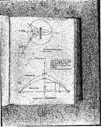
■ . . Fie- 3 .3 (a ) giiows. a ..diagrammatic ‘Sfia.tch o£ thq ... - ’
probe , configuration- assunins- that :L,ts position of yaw ....
'v ie -a free streaa of. valocity^ Y 0 is such .that the, f l ^ v ie '
•>,ancliBed at am anijle a to the shield axis in the dir«c-*' !
,■ tiun -at. .flew. .*The axial paaponent of 'the . velocity io .''
■therefore giVssn h.y V^Coao. .»••>• I f o assumes.any v.alye Ion
...than ufiity ijaeh that th.T&tfcliflfl. takes place, K* vouia /be.
^J 1a«'ll ttttfl fraetiortfrl.vhenc* Ve can be written as..: .
.- •' Ve • = K fV0Coaa , ( 3 .12
■ v - (refer equation . • ... ■■;-■■ - •• • - • .
L
-.<• ' ■' . .. « w « t . i i i , ; ,v I r6«S, » , ^
. - « * . » * « fi o y ^ ro„ 8K: ihe s^ , , '■
: ■ ~ ' V ; ... V ' '■ A -■,>■?.„■;. ■•
t t i . httM S- rt. Sm ^ * . 00 » , « e i » U i tte
n x o f .% o i t u n ? aiode W 1V « i » I t „ „
' t 4 . . . 41y „ . « » « rtrolt, lo aot M
a ;<eyiia*., .it .V6uia pasfi tJiroQgfi x tttW .''■'. ' ' -
", ■. Saia* 'ss- ;a' ^ i d ;j«ass8a ':eJectrtoB ’ i i
-• i * reside a vjiere
, ••*»*'*** Vg.&nd: hence imposes a ;vtn4*off* ^^iti>D'a,«'a the ;-. •
; ; ta i^ u a ^ a t ;:*r6S'ervoi,T> ’. '■; tfiujj^;frev?n * s'.;s iieak^*M ^:«row '
/ Beset rating,' ift-ilie - eaine manner' «js .tJle •elEctrtnVflov.io' ’.'.'
’.;■ ^ raive ia teriaiEat'ed by tke cut-eff'TOl^age’-ozi ttoes'.&ria. .-
j''.«. .-p *ceora&ii.ce vifih. -the tlieciy ■e.xp oaadea *lo=rej ifc-'' '■
■\ catt -al^o' be' s&os^i the anEie .of to ' ■ ■:
.tl<ni -dittec-fciAti 'is...iisere&se4 as e inereases.- ..=■''"'V'
:'ferrinjj to F ig ,^ 3 . 8(;fe Vl,tk«.;.relati&aShii> '*':K, V0 Cosa;, ■ ■/
.••I'flJSV.-tvo - ideiitieal^Aies differing only an dianete?, o ? , ,
^ ' j" ■'• V . V ' / Vvesting o rific e , nay be. ili-uotratsa grapiiically'-aS slvtmu •
FJroSes A an4 ’: BiLave o-valucs o f and ag* respectively.;
..■ Wfeare o^ > fee aiaher tfValue would,' se'eesf-aiiiG to '''.'
tbiJ.'tieory, cause lees throttli^-fi and hence’ a Jugjier .,
. as sfaovn ai.agtaaoatieft-llyi; ' ■ -
' ^ « * » w
for t « „ lt fc
» r if iss ,.4 li .r t « ;, t fe f.fl,:; / !> Y ; '
r . . . » a * r > « . « „ toTO. , „ j /e4 in
« . „ u , g. „ . „ 1<ioitri if6iiu
impose a Ve-value at wl,lch „ OJ,14 be xaeatu-sl,
or approximately so, for the two. probes^hen subjected to
, . oblique. flow-. . ij • I f tflia -Vb~Vb1ws rig- dencied .>•?■'y- i n - - v f : ••'• ’ ■ ' i; " ■ ■ •■■■'", '
; Fie*. '3 *Gf* 3 i ; J ie /c ietr -pat.prolse ;A youia ha.ve a. v i* .*
. .r a n g e Q a g u i a r _ ia a e a s i t iv it ^ to:f|o^/d'iraV^ian tUan^": . -
probe. B (tig \ .fy 'fr '■Y
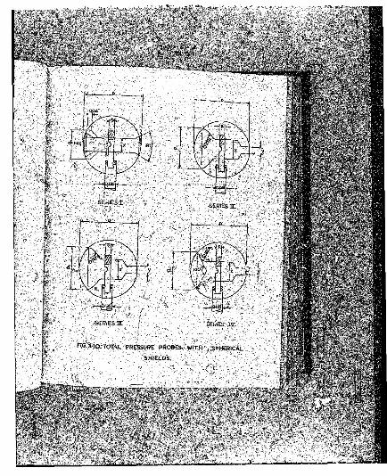
3 > 3 .2.■ ■■ ■Sxjp-eraEient&l Tiracedura- -- •"*• ' - ' '
I +•,. Jpte forego^ng tlifeoretical anai-y^ia.-fittggested tiif.
■■ follotfine ’experimental procedure.'-'-'' J *, y.y' “ ... . -
. . .Seieot a suitable ahieii'diaisSter. ;■'■
'■ ' •■■ ■ s'- ' .. :'3'<i|.2.2 ■ ,Select an : initia l .sise ^for^prcibe en£r&nei
disaster*'- d . . ••- As a tit e a earf,ir>t the -pressure di«tJri1-
,■'faliSiitt on'' tile 'uJJatyeaa.-face a-sphere; Sof \flowrQund ■
/''ii\BftrVe#'-'aS'.-a-'Suide { '\ ; ' ''V"'.
» , I ’ . ,. ■ '•. •' '. Tile pr&’ssufe rcoeffioier^ Cj,, tot a San. “® .• •;
defineSf a? : • '■ ■'. ■ ^
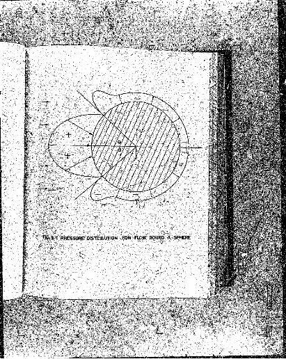
f I * . - . „ ^ ^ ,
* » * • g : M „ . * . , . • „ « }B . . ^ th>t (te,
o„«nx„s . W l a w t „ * kleB. t t l „ tle ^ ^ ^
«»»„ . prow; viiu> rof •_
■ai
o i » . i , « ■ „ . « „ „ r i, a ^ sa<t to
t i» m m ror i , , t ' p» ; t e « i
l o f b u i bj, bile d i * 0:r »hi<*”c'
tea reauatio-n'" ( 3.1£} '.
-iris la
o s - •
sin5 6 » '$ ,
S ia « J 1 f
s y V ^ j * • 'i
^ ' i v -
Ji«yiee. i f B is taken ae inch, %- eSmlfi. fre'^dB
*lS>ro*a«(it«ly 0 .2 incli for further, experimental investt-^
^ g a t^ o ii . r G s
3 .3 . 2 . 3 Select values for ar and §^*uei that ‘t-fe1-;’ -,,':
ifKSftalfle ts?«HBiti6n hztvzejfi d and x j.’B possible, :$.$&■ :en^ ' .'
. ths biWfaisfr effect of 0- ia neglifp.'blfe, ■■■■..£-* •
out - different iflt&en&l diaensioas, ftsubjeeticg .cam-,
^natiotia of 4 , * and 0 to p^erietentaj, testing, for
. constant y , and dete/ao-ne .-fc&o best ,»laea-: fop 0 and - ■;•* .*
■ i . SMV procedure .«& He . f c a o ^ ^ e s e ah^uid : be: dj^tat.ea L
Sy experiad&.-«al vt<l>a'e*ssrai’«)ij. " • ■;:■■■
SSil®
m w ^ m r n ^. 3 . s , « . ‘j « .
, . , * •
* * > * « » « > • vuu-
^ ' * ' 5 * ‘ " i U °i " * . ' ™ * » * < , l , » m>
’ • * ' « « * « * h « w , . .
‘ / V '5 * ¥ S I “ * * » ? W l « , { * ! *
* » *11, i i h i r f j r - t n ta>«io#s „ H t tm n a ? a ,s J
" " “ * « * « * W » . s « - a , « . * ;„ M I M b n a y v 4 . <
’ ^ t .
L t . t « |u . 4 . . S * „ « . a .m s.- i, M j . ;
1 » « * * > » « « , » „ „ 4 ~ « » ■ % . * i O U r >
tSta a « « v „ « ,„»- t t t M ln^c t-!le a!jhe e< tkl> M
Huioi znaiblAflnrtzg B . _,j l e :
e/Jj&sa ©f iiaBeiei. oj-3 .|j
P O J l a ^ g tie f f l A ’^ n »j| t il tt.m - rtica muOjr.i .
t on ii-e ief,f^«ts :p f
'3?wti«paa*s*q,3f; t $ e
> wc i.avesnlg0,tid!aa 3
• « i*e W weiiS an^ ori fice.
3 .» . 1 ,fe£t, j e s ^ m i . .
Hfce fojiovifls i4
/. ^■KtaS-Is the- i-eadfer i «
.orifi-ce* • • . j •...■-< -.....■ ,
& , ^ 3i t i Ba j y t ^ t f c o a o 8 ^
f a costsnsianai^E Btwusa«r.;
re<f*rre£ ^er-e^eV^t..,..
i s H i a s
; •
*
? §
V
• 92 .
: : : : : : : : : - U
Of serio.fl ii'.
‘ * " * <t T . J t a $■\ , * « tite f £ a a l t . , S ^ ’ ->w n il
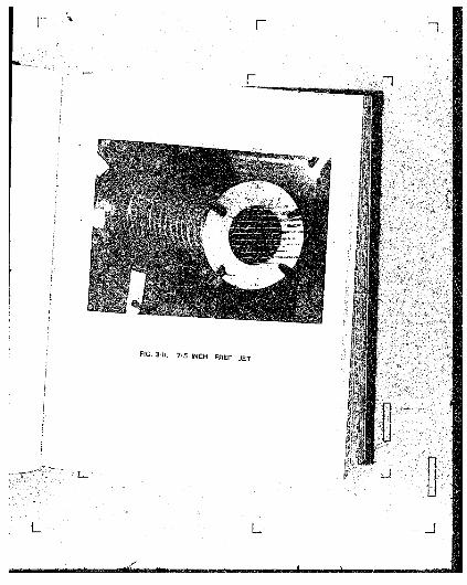
• M I t , » , ‘ " *“ * '* “ * 7 - 5 ‘ “ - 1*
* “ 1 T * * ^
“ '* ! ■ *••* — » * .
. « u - » M
<sf 220 fte/seii. ;,. -
" ' r j ' - ' ' *. . . „ » . t m „ m M e a ^ ^ ^
^ r r r > v i t M „ „ ^ - ns ^ ^ __ f ,
' " I - . 3 . U . * “ s i « » « y a » w s i a t , - W m « 4 iB
'0ne *«* «y « F » t n « n on th« i i n t T t t i i A 'c f ^ u s
v t i l . , « = „ , „ M a l j ^
>>y j M k u , t h . , » ! , » ! , l|u! , i o d « , on a lM h 1
«»CtB«d accurately „„t t .M h « W , i ,,rf1Jh„ , „t „
, i ^ t r a e - t o * ' , - ' ... -■ ■ . .. .
” " , fv
>.; ... Headings ware taken at constant Air Speeds ' •
Pause TO ft/sec tlo ST5 ft/sec and were referred tn +h»
centre-line rseorrt obtained for zero ■ angle., o? attack.’
Jesuits ays pre&eatad as percentage,s o!C the centrs-lino
u . ..iv zr ;::;; 1 "**- „ „ u S-inrt iiaacteraeaaureneutsi of flerI B6 Tr ' J
' „ „ ^ " > » « « « *■ « « t ,° 1>* 1 tS*t *»rtlo« T , . fc
f ~ W t „ t , . „ i / . « u .«*xes IV and V r . 5 i«ck '
36 1M 1 free iets iHc*
‘ m r i . » ,4 * * *«> 4r fte a U (i„ r> « . nu> i „ t i W m *
aJljr » 8 « » » « r „ „ r d » ^
1 \ \ " * * ' • — — * * « £ w
> V ^ " ” * * « * = ' « . ■ » * . . « * » * / . * , , ^> o f 220- tt/seo , 0 , o
‘ T * ‘ 1,014 in “ “* • « > * .fetal rtM p i „
- * 4 » , . 3 . 1 a . , A p e i .i « w W L m s i ot<-
a . « « . « , llr . „ t i ,
» Jitea . « « « ' * , . ij, W a j ,- ,5. , coui4 1 * ; :
by; ^CBaBf; -the Rlobnl vtth a loUatj&n rin wtieh
; ■ " " * * * «« * *~^Ji • » t k t v » £ s l ,^ ,y ’w » , 56m.
.<-'5^’o'tsl-a'etoj .'. '■ - : -- ••■'■ .-. v..; ■ ..- ' ,..
. S ' f ■
*-»’ BStufbngs ware t?Uten at e x t a n t air .’speeds in''the
; * afage TO. .3Jt/a.ee ,.to 2?5 ffc/soc aftd w r i reW rrei to the "' •<
r cfeftVt-li^e .recard obtai^-id for .rerd angle of a*tack. ■■'■ :
.•,Heavjn,t6 -iire..pE9a6ntea as jj^centases^af the ;6«nt're-iine '
tre 4c- •& ^ far .enee sroliD .aynainio
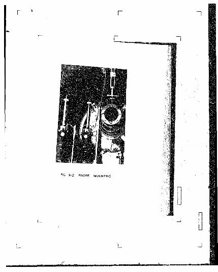
•as mounted .os thean n* -r»
tao Game noint^'-k'sK- ' .-'. •■.',.1 ; .'. . ■ • ■ ■. ■.. .. . * ■,*, ^ ^ <
. . . . ’ *na.iaieh chkracteri
. ' ■, . Ir ' tent series t too
* m t , U v i Pi
' • i l l , duiriag the initial,
teste
also eXttflx.na.tdon nf +h«..dr w ^ io p s s * or « '
•M M U n r a t la th . raaB„ 70 * t / , . c to ej5
'sddi'fci.c*n, tie response .tinea. yere.:; det.eiijiv
the two final versions of the prohe under «a<$aenl-4-
'air. pleasures, of 500 mii yat.ej* gauge. : ' . ' ^V. '■'
'• 3.itf2 ■ gest reenlts - .. o
/y' ^ ^ia this.: sut-.rec.tion. the results „ which are des -
ifc,-ffetail. in reference.- >i> are suams'risea. • . . . .'■.
•';>"' .The »xpeti»ental 'inVeetigatioh' • aimed'.nt-''AeVel '.
“ e » b i .ld. a *4
10 tte * '“ * * *« «w .» .» , tt„ „ , ,
‘ ” “ “ * « • « . « . ! < » „ ia “ *■ l “ ' ■--. P M o t i e a ,iae o i > ; ;■
0 . 8 “w . ^ , *„„« „ a u .
^ ;. ;.■-■■'• . •- ■ ■’ „ ^•• .:•■•• "
^ I T ‘ ' " ° 01 " " * * ■ J“ * “ xra * m s * • * • - « * *
f * « • « « * « » . * . . . y « £ » * .
« - * . W . . inflyei^ce, . . „ „ 4 i w 4
;. t ^ o r e.tiftaliy< ' See Pig, 3 . 10, » * * ; / ." ^
«<,. . « « t t „ U . 4 Uy ThuB, for thB coeffi_
cieat is linity oni'.for <j a, 0,-fc. *- * 1-’ ' ; --' •’'■ .""
4 P ;
r < V ..
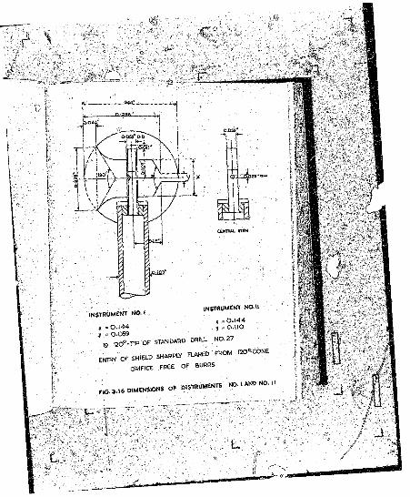
x » 0 .1 4 4
X = 0- 059 _
s 120°-T1P Or STANDARD DRILL NO-27
En t r y o f s h ie l dSHAH Piy FLARED FROM ISO^-CONE
ORIFICE F R K O F BURRS
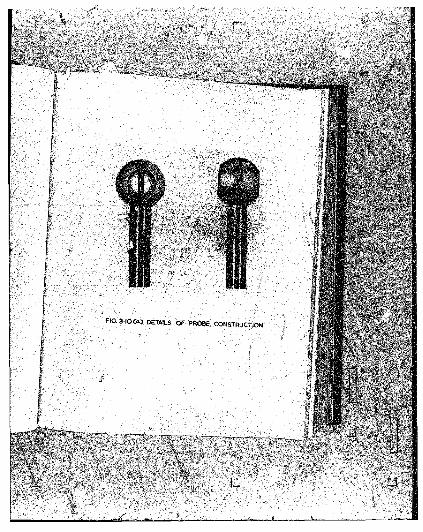
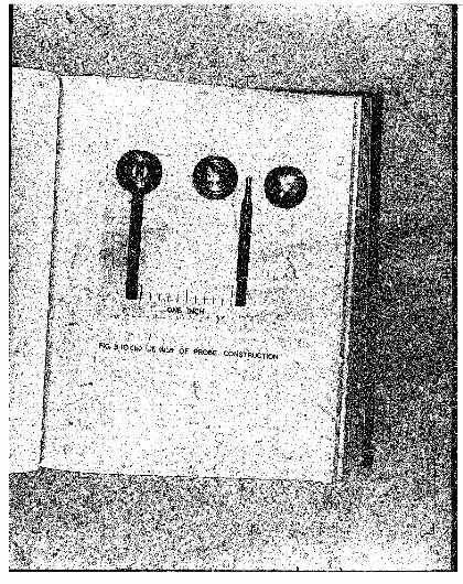
F1G. 3 .1 6 DIMENSIONS O f INSTRUMENTSNO. 1 AND NO. It
probes.
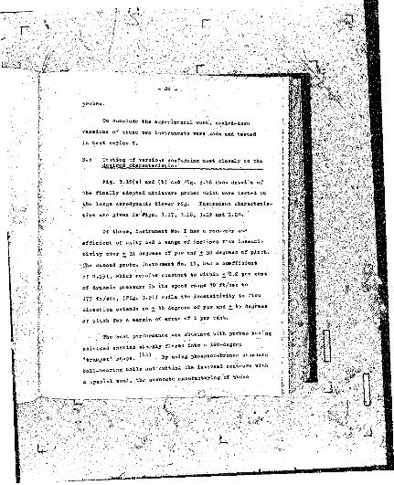
To conclude the experimental work., scaled-down
versions of these two inatraBeafca vora Made and tested
i n test series V.
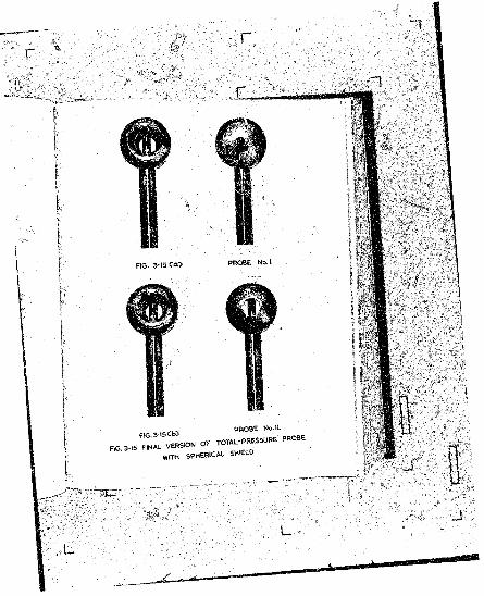
3 .5 Testing of -versions conforming nost closely to the desired characteristics
' F ig . 3 .1 5 (a ) and (!>} and Fig. 3 .16 show details of
the finally adapted oiniaturo prohco which were tested on
the large aerodynamic Mover rig. Instrunent characteris
tics ore given iff-Figo. 3 .17 , 3 .10 , 3-1? and 3 .S 0 .
Of these, instrument Ho* I has a recovery co
efficient of unity and a range of inclined flow insensi
tivity over +• 31 degrees of yaw and ,+ 30 degrees of pitch.
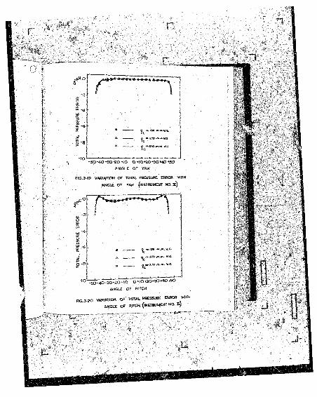
The second probe» instrument Ho. I I , has a coefficient
of 0 .5 9 1 , vhich remains constant to vithia 'O.Z per cent
of dynamic pressure in the speed range 70 ft/see to
275 ft /s ee , (Fig* 3-21) while the insensitivity to flow
direction extends to + 1*8 degrees of yaw and + 1*5 degrees
of pitch for a aarftin of error of 1 per cent.
< The best performance was obtained with probes having
flhidlded entries sliarply into * W 0 - a .g » .
, w , . l ‘ l> »y « " * » « ■ * • »«• «
» U > «i>4 e u t M M s « W r = viti
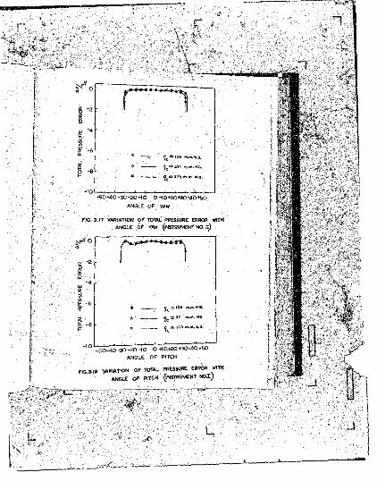
-50*40-30-20-fO 0+10+20*30+40+50
ANGLE OF YAW ' .
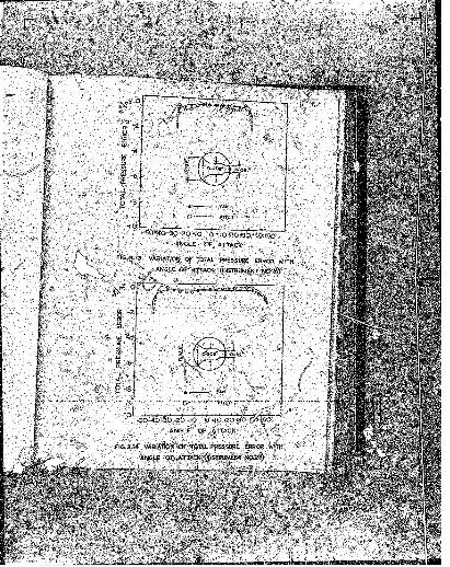
FIG. 3.17 VARIATION OF TOTAL PRESSURE ERROR WITH
ANGLE O f YAW (INSTRUMENT NO. f)
-50-40-30-20*10 O +10+20+30+40+50
ANGLE OF PITCH
FIG. 3-10 VARIATION OF TOTAL P « S S » £ EBBOR WITH
ANGLE o f PITCH (instru m en t N O !)
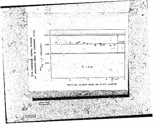
FlG
. 3.21
DEPEN
DEN
CE
OF P»OBE
CO
EFFIC
IEN
T
ON
RE
YN
OLD
S
NU
MB
ER
IN
ST
RU
ME
NT
03 . 0 % a )5*3 so ~ £**i 7.- * % <P oo “>
-
K - 0-991
I 2 . a 4 a->io
REYNOLDS NUMBER BASED ON SHIELD DIAMETER
■» s
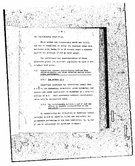
was considerably simplified.
These probes are structurally stiff and robust,
and due to simplicity of design the response times vere
uniformly goad, being 50 so jli aecoaia under a suddenly
applied air pressure of J00 nn vater gauge.
Tae performance ana cnareccexiaticj* or tnese
miniature probes are therefore eojsparalile to that of the
original Kiel probe.
3 .6 Comparison between theoretically defrayed flowcharacteristics and those observed daring actualprobe -performance . '
3-6.1 The effect of 0
Bxpariment confirmed the theoretical result that
ya = x is the dominating geometrical probe parameter, and
sbawed the.t probe performance is dependent on a critical
e-ralne of 0,1*, This apparently critical experimental
value w ill "be re-examined later.
3 .6 .2 The relationship between <a and K' and the* * effect on angular insensitivity in yaw
and pitch ----- ---------
By substituting «he dimeasioaa of different probes
actually tested in equation (3 .10 ) and evaluating the
parameters pertaining to tha teat conditions, V9 , Vr6 aad
K ' can be calculated for different o-valuea.

coefficient in the vake of a sphere, is -CUtu Because
part of tie flow is'.divorted through the spherical ehf,'*ld.
however, it oeems reasonable to asaune that flow ronBd:'ifehe
shield would d iffer fro’u that round #? whole sphere.
Two values of Cp were therefore used in the calculations,
i .e . Cp * -0.1* and Cp •» -0.2. At thia stage it was
thought that* use of different Cp-vaIueB Bight show tip
the effect of Heyaolda number on probe performance.
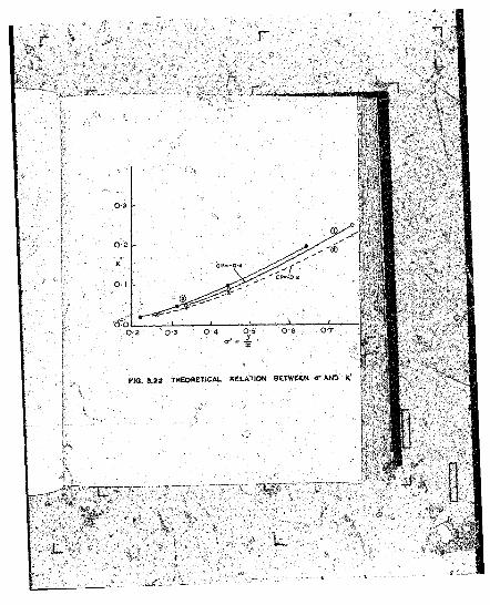
She probe dimensions used, toaether with sample ■>
ca-lculation.6, a.se ahcvn ia fietail ia Appefldi* I I I » Table
I I 1 .1 end. X X I.2- . She ses’iilte era gi*rea £>& graphical
fossa ia Fig- 3 .2 2 . 1
Graphs Uo. (l ) sad Ho. C2) represent K»-values
as calculated for corresponding o-v&luea, for Cp = -Q.%
and Cs * - 0.2. These graphs lie fairly close together
and show that Reynold# nunber effects beooae nore aarked
the higher the ©-values| vide perfornance »£ -grebe
Do. I I (ff » O .766) compared with that of probe Ho. I
Co ,** O .Itl). KraphB also shoir that C^ is not highly
c r i t i c a l , ‘ . ■
lo eleeK Brapl», the « »
r t . r o u « !3 .9)> « < « • » ■ 0n,! " tt*
tested prola. ka»ii»<S » «jl« ie dim eter « I °-34 ioc» with
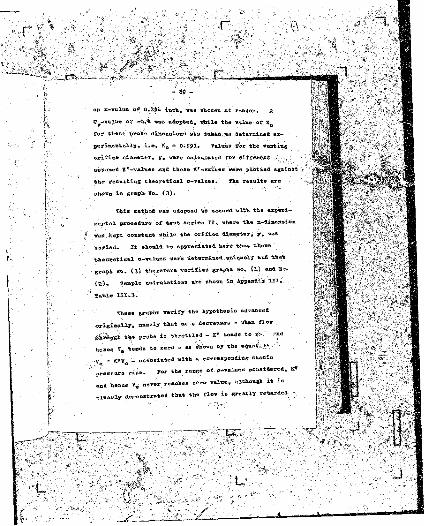
Cp-valua of -0,4i was adopted, vhile the vslue of Ko
for tbeee s*ohe dimensions was t&Jssn ua dster&ined ex-
periQ=a4Q.lly> i>e. K0 “ 0-9&1. Values eat the venting
o rifice diameter, y , vere calculated for different •
aes-msed K ’ -values «ztd these K' -values vers plotted against
the resulting theoretical ti-s-aloes. The results are
shown in graph So. (3 ) .
This aethod was adopted td accord, with the exjeri-
jaeatal procedure of test series 1X» where the x—diaension
was iept constant while the orifiee diameter, y» va*
Taried. It should he npprecia.te4. here ttat these
theoretical a—values were detersiaei uniquely and that
graph Bo. C3J ttaerefose verifies graphs Bo, (1 ) and So.
(23.. S»»ple calculations axe shown in Appendss
' 2 able I I 1 .3 . •
Shese graphs verify the hypothesis advanced
originally , namely that as a decreases - when f3.»v
tfS k 0 ie tfn P ~ b* 1* tarottx.a - I ’ M i « . ^ tft
b B M * . « « » « « »• ' “ '* * “ > » “ * '"** ’* - K,vo _ associated with a co." respond! AfS static
“ « W
and h .n c . V . n«vtr r » « b « » n l » , U U « * “ “
4 .» o » « r . l . d « . * « « « * * • * « < « « * » ,

from, a in tie free-strean, where tlie velocity is ■
to the entrance zone of the probe where the velocity
is Ve . Consequently, as originally hyjKsthesiaea, the 1
matheuatieal model simulates conditions prevailing when
: an *eflay ftir ciss'A.ion* forms a 1 reservoir* under pressure
in the trumpet entry sone of the probe.
On applying the above theory to probes1 in yaw or
pitch it vaa shown, theoretically, that instruments vvth ,
hiEhes a-vjiVueB should have a vide? range of. insensitivasj-
to Flow direction than thosii with lover 0--values. (Probe
A and probe B in Fig. 3 .8 (b ) ) ,Bxp*rittetttsl-.'y. determined
ch&raetaristies of probes Bo. I and tlo. I I this.
Probe Ho. I has a cr-valne of O .M and a insensitivity
range of + 30 degree of yaw and pitch, vhile Probe Mo. I I
vitb a o-value of to d t w r t i w ♦* ■ .
flow over the range + U8 degrees of yaw and + >»5 to jw a*
' \ r pitch. This is further proof of the validity of the
hypothesis advanced.
3 .6 .3 Helatioaship between a and Ka
» , 1 , „ for K„ ««r« c .l c u l .t .4 for .- » 1 —
« { « V ™ 1” * °r * ° 'a “ J “ d ‘ “ '“ 1i „ . w » t io n 0 . 1 1 ) . T h . - . 1 *
w . . . o ) •»* >>■>- « > * » I i E - 3- 83- s m l * '" a ~
■ culations i . » W * » * « * • * *M 1
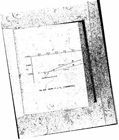
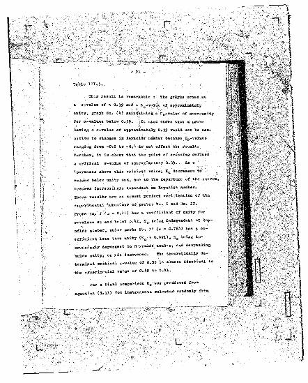
a o-valuc of *w 0 ,39 and 41 K of approximately
unity, graph Ho, O ) maintaining a Tt0-val«e of near-unity
for c-valtias balov 0 ,3 9 . ilt also shewn that a' probe
having a 5-value of approximately 0 ,39 would not be sen
sitive to changes in Reynolds number because Cp-values
ranging from -0.2 to - 0 . it do sot affect tbe result.
Further, it 16 clear that the point of crossing defines
a critical u-value of approximately 0 .39* As a
increases above this critical value, KQ decreases to
values below unity and, due to the departure of the curve*,
becopeo increasingly dependent on Reynel&s nuaber.
These results are an alaost ptrfect verification of tic
exgeriaental behaviour of probes So. I and .fo. X I,
Probe no* X ( a O.lil) bae a coefficient of unity for
r valu es at and below O .U , Kfi being independent of Say-
aelfts number, vitile probe Mo. I I (« * 0.76^3 Ha1* a co
efficient leas than unity (KQ » 0 .9 9 1 ) , K0 being in
creasingly dependent on Beynolds number, and decreasing
toalov unity, aa o is increased. Tbe theoretically de
termined critical 0-val«e of 0 .39 is almost identical to
tbe experimental value of 0 .^ 0 to Q . M , .
Por a final comparison K0 *wae predicted fro»
« 4n.atioo (3-11) instruments selected randomly from
those tested. The experimentally determined average
K0 -value for probe Ho. I I was 0 .991 at a o-volue oi
fl.76*>» vh.il* the average theoretical value for = -0.2
and -0.1* - was. 0 .997 - a discrepancy of r>«6 per cent.
For other instruments the discrepancies between
experimental and ttheoretical K0-valueB lay between +1.2
ajjft -0.01 per sent. .
’In the light.o f this nssnifestly eatiefaetory agree
ment between theory and experiment, it is submitted that
the theoretical analysis is sound an* the hypothesis .
advanced is acceptable. It han Tjeen sii-ovn that the
mathematical model not only explains probe performance
hut alpo enables probe characteristics to he estimated.
3 .T Manufacturing of Pr.obes
Experimental versions of the probe vere made in
tV> j For th« n w i o l r t i .W , HoffMaoa .tsod.rd-
, i * . ball-feearinB M l - » « « " • » 4-
lioid Is » t o i l U m vioo by • • • * • of spherically « «■ «> -
< M k .l ip blob*. M .r i w f » * * > »» » '">> th" •I "1* '*
could M lo o .t .d , * « W »»d o r U l c w .
firiiled out M « • 1 < M vort.d to tt« « « « • » .
Ih« v i e v * . tbon u n r f tlroaen 90 d«Br**« M « th« * M .
holes drilled.
The stem was built up of stainless steel tubes, the

' ^ il - 1
_ - ;. , r ___*....
- 9l» -
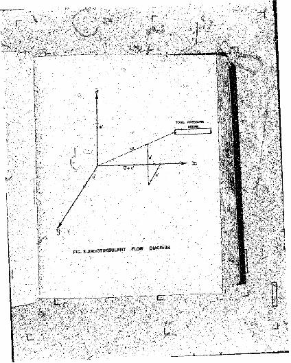
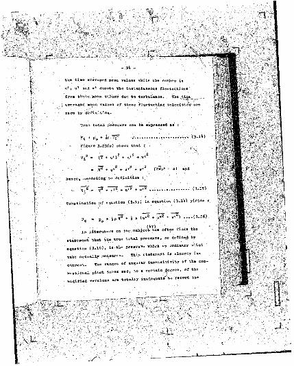
•the ti»o averaged Bean values while the iaafaea in
u* and w* denote tbe instantaneous fluctuations
from tlieee Mean values due to turbulence. Eho tisj.e
averaged aean values of these fluctuating velocities are
zero by definition.
True total pressure cun be expressed aa x
H * » » '* •» V ..............
Figure 3-23(«) altovs that s
- + u»^ + + v '^ (2Vof = o) and
beade, according to definition t .
T f . 7 ^ ^ ................. .. (3 .15 )
Substitution -trr . w tlo» (3-15) la . w « m » <3.1*> y1*14' 1
% b i 2 * W 1“ „ . 2 * »-2 ) . . . . ( 3 .1 6 )
In literatur. on th« .rt ju c i »»« » « • » findn thf!
ttot tl» « » * l °t «1 » * •■ » ” > *■ * « « ”«# *»
. „ « ! « ( 3 .1 6 ) , i» til. »u< ’» *« I 11" 1
ttfb. . o t n . W « » « » • • ■ Itls " cl« “ Xy 1-
e M n c t . » « * "«• • “ * » ® “ »* o l U w »• » -
v .n t lo .^1 ritot « « » . . • » * . » • * ° f “ •
u t i t i U T .» . l o » . «r« totally *■> ” ‘;” i ,h '
(T + u*j + u '2 +
full instantaneous components of turbulent velocity
fluctuations. It would be nore nearly correct to state
that these probes register : . ■;
■ Pt - P3 + JpT2 + * * ,e * v ^ j- - .. .. .{ 3 .1 T )
vliare S3 depends on the instrument's range of angular in
sensitivity and the degree oi.jf turbulence. Conventional
total pressure probes do not register true total pressure
as defined ty equation (3 .16 ) and at the saae tine the
t&mporal mean velocity V determined by aieans of a total
pressure probe in association with vail static tapB.ic.es
would be in error because S » 0 i& equation (3-.16)-
The, characteristics of the spherical probe (in
strument Ifo. I I ) , however, are such that this instruoent
would measure true total pressure in turbulent flovs more
accurately than conventional instruments baeftaoe of its
wide range of angular insensitivity. When u«ed to de
termine the temporal raean velocity at a point, a correction
.factor should be applied to take care of the.turbulent
component of the total pressure registered. This
correction factor can be determined as. follow-»
IT at is the error coefficient due to turbulont,
Components, then*.
The true total pressure is given by equation {3,l6>
which can be written ai s
Compering -iquatia^B {3 .18) and (3 .19 ) it is clear that s
Using tho root mean square valuee of turbulent Telocity
(its)fluctuations for a pipe, 'Bay, as determined by Laufer,
the magnitude of fl^for pipe flow can be evaluated. It
sUouldbe pointed out, however, that appropriate total
pressure corrections for turbulence ia other flov sitTiationa
are , at present, not possible owing to the lack of ex
perimental data on tfce structure of turbulence.
Determinations of r .m .e . values of turbulent velocity
fluctuations, particularly near solid -boundaries with the
aid of the newly-developed 'hot-film' techniques, along
with more detailed hot-wire anemometer surveys of a
variety of flow fields are urgently required.
It.2 The- effect of swirl
Swirl continues to present problems in flow measure-
« . . . Preston .»•> «ortu,jr (7 ) « » » * « . « . »» « • * " •
of . ” 11
a svirl constituting a 10 degree choose in flow direction
caused an error of X jier cent in the discharge determina
tion.. They ytate that : ‘ The errors arising is a aster
using pita* static tubes vould depend (rj the yav
cbajraoteristiea or the pitot static*. It would* of
coarse, also depend on the range of angular inaensikivi-
ty in ’pitch**
s -' Again it Sfcoold be noted that the aliaraeterisfcice •
of t ie spherical probes are auch that tlie effect OS svirl
woald l>e aioijuised beeansa of the relfctjfeiy irifie iftages
oS angular insensitivity.
fc.3 Correction for probe c-stttrs l i » » displaeeaftat
tifoea a pressure probe is placed in a shear flov -
, „ ! « u .« m n m r . i * »<* « » t »!»*>* u f a o l lr
M U at «>■ poir-t o» o a »r<** « « •* * • li>w-
t m » » a >!••» ! *3) « “ » * * » »
t » .t tor . f it ” * » " » • t a i « * r' 1” * *
io l a » o f 0 -6 , « •
« . « * • •» » • l « > » « « * “ ■*
o.lfl ti™ > t M « - w l » **-
jo i l .d tfc.t >«
* « “ *• “ * W >
l W ) “ * » - ” *= “ “
» „ t . m n . . .J>«p-lira*« <“ « • * “ * ’“ * * “ * '
cated problem which demands further attention Dis
placement values for the spherically shielded probe
have, as yet, not bean investigated.
not trujfly applicable bactuseit vas determined -under
•outer region’ conditions - to develop a relationship
which defines the displacement aa followa i
where Ud = true measured velocity due to displacement;
'2? ■ true velocity at point on centre line r»f probe;
Cf = local coefficient of akin friction}
K » function describing turbrilent velocity distribution i.tt the 'outt'r region* in pipe flovj r ... .. .
B* <* the derivative of the above fxrtiction. .
Cf is functionally related to J»D , the pipe E^-rnolds tiumber,
and can he presented graphically as shown in Pis*
vhenee the factor
= dies' of probe}
B •» auc'v jiwseter;

4
2
O l 3-5 4 0 4-5 S O S-5 6 0 6 5
l o g (o h d ^
FIG. 3-24 SKIN FRICTIOK CQEFF. TOR PPE ,
I— -
- i
\ } X
= § 5
O 0-1 0 3 O S 0-7 O'}
- VFJG.3'25 CENTRE U NE DISW ^CEM EN^SJCTQR .
F OR PIPE ‘ ’
\ } $
j c k ; : , «
M i f i • i f
I 1I'.
Filp

can fce expressed ia terns of it * — and HB, y
being the distance froa the duct wall,. Tima, the above
factor can he presented ift teras &f ^ hy aeons of a testi
ly o f graphs for different values of (Fig. 3 .25)
yielding values for the correc&ioa factor .
« . r " - ; for typical practical values of aa defined by ...
- .. D ' S iequation (3 .2 0 J . . .
Applying this method to a spherical probe of dia~
aeter 0 .3 inch, eperating ih a duct o f , *ay» 8-incfc d£a>«
« ! » « ! » • « i »»■'“ « w “ * 1*"
unity, while
Worn w . « u . *t « « ■ » • * »£ w “ . "■* *»■
n«r c u t . (M 1 » • 1 * « » *
the correction factor SSor a poiat 0,8 rncli
at i
preximately 1.006 <
correction geeaa > high.
" ^ ' B i . « « . P 1 « i* «i‘ . 4 « ° r
r. . . for the displacenent error,estimating a correction facto* r _
. . „%»«« iionever. equation (3*20) wouldFor spfces'inal proDas * nove^e*» »
not » . « * ■
« , « « „ f 0 .1 8 , . u l « r o t a « , . . . > » « « * « “ ->“ « •* .
pro\je R&ometry. -
■ , „ « u « . « i c »„fi8« . t i o . Of -
where flow takes place through tfaa probe and pound a
central, cylinder, v'nich houses the pressure opifi^e — £®
not exactly comparable to the conventional pitoi-tube
type of instrument which h&e a atasnsrtioa point at the
ip-Strttffiettt t i j . therefore displacement errors for
probes with spherical shields must be studied and ana
lysed separately following the eiethod described above,
APPLICATION Off sgHB SPHERICAL PROBE
At the beginning of this chaster the necessity tor
tbe a&velojaen* ot an inprov'yd-type .total pressure profee
was emphasized. The Kiel probe has so far been the oa.ly
instrument capable of measuring total pressure.accurately
in etrcmcly three-dimensional flows it ia* however,
clear t e a . U . « !“ « *■ * « « « “ “
several identical « » » H ' i M W r n M M . *>*
visorjr Committee for ioro»»«ti=« »ns t»»t*d tli«»e in
struments, tW tie o l o o iojt.a » 1 » « 1 i « » • " « “
t o t . r . For n m ,* » •“ ' " *
1, t »« .W all p * « . W . « • « ! » * A " " * * * * " 1 »“
• M l w . f J investigations, a prrt. of 1 i«i> “ * * « «
i , t o , M 1*T. . » U * > » * “ ** •
flo» Inclinations o .» M * • '■i S» “ k5
I . . . . u , o . . i » i . to . . . a . . . f * * 1 » ' * * • » " • " ” y* * " *
BtrottGly »r .« - d i ,« n .io n t l flov riel* « • » « • • •
- tional i » .t r n « .» t „ » i » S t» * » * • * » « * * ° * ,
ineenaitivity to angular flow* Tbe spherieojt probe vfaich
has been ieacritea aeons to bridge this gap.
She autfeor is of tbe opinion that the perforaenee
t>2 this probe could be improved erea farther i f in tJu1;
oanufBctarias process tbe drilling est of the internal
jrohe contours could te performed ia one operation on a
jrtiY^ose-nsaae driXX>he&3. Abrupt changes in internal
contours and burrs could be altogether. avoided vith the
resttl-fc, as the experimental tread. iadeeS. iftttisafcefi* tha»
angular insensitivity range could be increased t=o £ 50
degrees, or sore.
33B3SCAL APPtlCAglOS . .
In Chapter I I it w.tts rej?ortt=d that the author ia at
present BssistinE two heart i»pe«i«3.ists, .attached to the
Heart Unit o f th« ilaiversUy or Pretoria, in *a
to isolate static *re**or* Iran total preeeure weaeure-
ments in blood flow*
Vhien e catheter is asserted into the heart ° * ’roin
t* d o . , M » r f n n *™ = *«■<- ” r “* *
of « . »«■ > ■ > « • » * « 4l” ' "
U « M 1 M .*:=»• »» l i » * !t* ” l*
, ! .> * « to angle oi f l™ « » • » « « * l« « W « l « a » • *■>**
* r » t»**l j M M r . *ottH 1» « < * * • » « • » «
* . » * » * » « “ * * * “ 11 ^
constructed, (an small as practically possible} and
fatted on to a catheter tip. The instrument cbftt'iMsteyie-
tics are to be determined in blood flowing in a one-inch .
dia.»eter transparent pipe in a circulatory systen in tbe
laboratory. The high viscosity of blocd. might .impose
a sis;* limitation on the probe fos reasonable reaction
t ia«» Should this be so, a email pressure transducer,
built in behind the probe head in the lead, might have
to be considered. ■ >
®«* Heart Unit recently acquired an instrument tor
ti.csnra.-te aeterttination of flow volmse by tbe 'gulp'
Method, described in Chapter I I . It is proponed to
determine the total pressure in the heart ofcawbesa or in
a v ein , after wUich the flosr volume and hence the velocity
can be estimated by the 'gulp' oetho<l» The static
pressure can then be computed by subtracting dynamic. .
pressure. Sroa measured total pressure. Thus :
„s . |Vu t J»US ) - iff2
« v , ■ f t - ' ’ ,2 , '
! » ealilr»«iOT * . » » rerert.t » • » “ » . “ ^ » « ' ■
» . . d , »» * « « « » • *>» « « l* * ” * * “” **
. M ~ *»4 * • “ * * • " l“ ° " ’
. W . i * . * » » v U l • * » • “ ^
» t i > th« * "> “ » • ,
Application of the spherical total pressure probe
in the medical field seems promising and i f the tests
prove successful -tie improved catheter vill be of
tremendous assistance in cardiac and circulatory research
end diagnosis. .
C0HCLU8I 0K 7 '
Two types of niniattire total pressure probe having
Spherical shields have been developed. The instruments
showed highly satisfactory performance charactbristics,
comparable vith thos>s of -the original Kiel and cylindrical
probes. The instruments are much simpler to manufacture
than the Kiel ana cylindrical shielded probes and are more
stable, The theoretically determined performance
characteristics vere confirmed experimentally and factors
affecting the accuracy of measurements n*d« with this
instrument have been analysed.
I t , autfcor t*at. t M o! t»« epheri-
a .l total pressure prot. v ill e o »t it »t« » .ig a i f ie M t f « -
yard step in » < rt .ld of total p r « » « « . . .a . u r . m . t ia
fiava or in flows involvingstroaely three-aiwensional flows
large angles of attack.
C H A P T E R IV
THE MS AS UREliEifS OF STATIC PRESSURE
BTfiODtfCTIOH '
In Chapter I present-lay i«#thod8 for measuring
static presoure;'vere briefly reviewed. As pointed out,
static or piessometric pressure in a field of flow ia that
pressure which would act on, and .indicated by, a
pressure registering device i'f it were moving;, along with
the stream so as to ba at rest or relatively ‘ statict
witb respect to the fluid. To design en instrument
vtoieh will record this pressure accurately in accordance.
with the above definition has, ae yet, not been possible.
Static pressure is a most useful parameter in
flu id mechanics for it is aireotly related to density,
temperature, fluid acceleration and velocity. Customary
Methods employed for measuring this pressure are the
following j
(a ) Wall static tappings or piessometer holes drilled
through a duct wall perpendicular to the -direction
' of flow;
(b ) static pressure orifices located on a total
lQlt ‘
(c ) single purpose instruments, v ia , cylindrical
probe with static pressure orifices. These
instruments measure static pressure only.
Hie re high, accuracies are W <red none. of the
methods referred to above is entirely satisfactory,
I b the following section the author attempts to-show v}iy,
PROBLEMS ASSOCIAfSD Wil'd STATIC PHEftGURS MBASUBgHEMT
At present, there are still many complex factor®
affecting the measurement static pressure, irrespective
:of the method employed.
When a small hole is drilled at right angles into
the wall of a duct carrying a fluid , the pressure ob~
served at such a pieaoaeter tapping is a fair measure
of the local static pressure, provided that the hole- ,
geometry and internal hole finish * « * * certain retire-
« „ M . Uncertainty m i - “ I l » » * w *»tl»ri-
t i „ ™ > o .r »iM « . . . M «r th .r » ! • » t »
difficulties encountered in . M . t j m « « > »» j r .o t i . . .
result in errors in neasurement.
Due to the hole-effect, the poasibilUy of sHelit
. I ' t i o or I . * 1 W » " * “ * in “ *
ideal piezometric tapping.
The problem of the static hole error has "been in
vestigated by 5 Fuhrmann ^ e* tr.9 1 S}» Hermann * ^ { 19 2 9 ) ,
Allen ana Hopper (5 °* (1 9 32 ), Kyadsu 55 11 (1936 ),
Rayle *52 (1 9 ^9 ) . Bay ( 19 5 6 ) , Shaw (1959).
Stretford and Ase-aagh. Cl9Co) and Livesay, Jaofcson
and Southern (1 9 62 ), These authors carried out
experiments under widely varying conditions and ex
perimental procedures as -sell as with different operating
fluids and apparatus. Their findings could be
summarised* as reported by Livesay et al* by stating
that the trends of different vail statie hole effects
kave been astablisfced, although jaarfcea disagreement about
their majjnitildes and true interrelationships still exist.
Static pressure measurements by means of a- con
ventional pitot-static tube are subject to errors caused
by disorientation between pitot cylinder and flow direc
tion} in addition, the positions of sero dynamic pressure
on the cylindrical surface tend to shift avay from the
static orifices vith increasing Reynolds number, pro
bably due to probe boundary-l®?** effects*
Attempts have been made to develop single-purpose
„ „ b „ . A t „ i » l 0«sis» »* °*« *» “ * * ” ■ * "«
i» .t u> M ill- * “ « « f“ *
of > tula i i» « ! “ » • « u'r'icVl ia **t I *™ 1 !*1 “
a ir.atioa 0 1 fl»n . « i .*lie »»»> * “ a «■*” " » ‘>“1—
and Reynolds number offacts axe clearly sources of error.
The needle probe and the two-hole pitot cylinder ana pitot
sphere, which are also employed aB single-pttrposa ia-
straments, have similar disadvantages. Alsot tar- .-
bulenoe and swirl cause errors in Measurements. C^e
effects and interdependence of these factors remain
sources of speculation; further analytical wo irk and
instrument development are clearly necessary. .
", In this chapter the most commonly applied techniques
are disalt with,and tfce p-esent level of Knowledge of the
various factors affecting the three methods referred to
are analysed separately with the objeat of clarifying
staiic pressure measurement. Corrjt^tictt factors are
suggested and .finally the fundamentals of ft spherical
single-purpose static pressure probe,j which was developed
by the author, are described,
HALL STATIC TAPPIffOS
The following factors affect static fcresaure .
measurement s
3 .1 Static hole geometry.
3 .2 The inherent static hole error.
3 .3 Internal finish of tapping.
3.1, Houndea i r f r w l . « • » »* “ f 1” 5
3 .5 Method of pressure tapping- •

3 .6 Variation of static pressure over a eross-
seotion due -to turbulence.
Considering the above factors it is clear that the
effects of bole geometry, internal finish and rounded
internal corners combine to precipitate the inherent
static hole error, liovever, due to the considerable
volume of experimental work coverine these iadividual
factors, it was deciaed to analyse them separately.
3 .1 Static hole geometry
The diameter of-a Static hole tapping has a marked
influence on the determination of static pressure. Xt
the diameter is too large, boundary fluid filaments split
up and impinge bn the fluid in the hole, causing a pressuse
above that e l 't&e true static.
. Irveg-jlar roughness in the vicinity .of a hole and
sharp edges cause fluid filaments to separate from the
v a ils , thereby indicating a pressure lower than the true
one. I f a tapping diameter is much greater than the
pipe vail thickness, stream f i l » « M » entering the hole
are split up atfd the result is an increase of pressure
due to the formation of stagnation po int*.. Dependias
roughness aaa diameter, there is an optimum
- 109 •
diameter cf topping hole.
( T)Treston and Borbury found that at a Reynolds
number of I x 10*1, for a discharge error of 0 . 1 par
cent, the maximum allowable hole size was 0 .0 55 iash in
air flow and 0 .095 inch in vater flow. They also re
ported that, for a given Reynolds number, iiole size was
inversely proportional to the mean velocity.
According to information derived from Russian
practice, maximum static hole siae for air flow is 0.083
inch while that for water is limited to 0 . It375 inch.
' prescribes rather outaiaed
static hole sizes, ranging fron 3/fl inch to 3/k ipcli, for
pipes from 4-inch to 0-inch internal aiaraeter, and l/£
inch to 1 inch for pipes having internal diameters of 10
inches and more. The differences in standards, and
therefore accuracies, are self-evident. The author
is of the opinion that static hole diameters greater than
0 .2 5 inch, even in large pipes, can lead to serious
Stratford ,» d i.cough <1S’ determined th . b ,„t
S o l . «ize experimentally V drilling out vith E*.at
care .ml pr .c i .io n . do*.n identical » . H Pl»S "tatie
hole, ol 0 .063 inch diameter. ' In these holee, lour
plugs having hole = i ° ° ° I ” “ °-011 “ °-M 3
r
- n o -
ineb were tested. The tests provided data on the effect
of static hole diameter which agreed well with Shaw’ s
sugocfstionsi, for bole aianeter correction and ore dealt
with later.
The sane authors found by calculations that Btatic
pressure variation across a boundary-layer vas negligible
and coafiroed by static probe traverse that static
pressure throughout tbe mam streaa vas constant. These
results would, of course, be .applicable only to specific
flow conditions and will algo be discussed later. .
They also clain that* provided the flow y» Steady, static
pressure can be determined to within 0-1 pei1 cent1of the
dynaaic bead by ijsaploying four 1 high quality1 holed;,
corrected for bole sise. In practical engineering, how
ever, neticulous attention to wall static orifices is
not always possible and steady flow conditions are .
rarely encountered, ?
"v, Tbs American Society ° f llecbanicttl Engineers
( A .s . i i . e . ) m > «■> <561 * “ “ • “ * “ * * •
i n . U 1 I • ! * • . r m tit illt i or » .light
. . j „ * .t This would cause a lower staticsuction always exists . .
p * . u « n 1 . R measured. A . . « U « a I . the . ! » » .
t l i . i'. “ “ * V“ W l “ * r'*'
W , i f . . p « « i o n « •*« *
In n t u u K (5 6 ) . il ” =l« * <1 ,h *t ’ I f ***
' JJT
'L
atreon is turbulent and full of eddiee, the pressure in
the side hole {static orifice} :*il? fluctuate irregularly}
bat. Tinder all . ordinary oircunstancea, these flactuationir
will he too snail or too rapid to affect the gance which
..will indicate the average pressure in the side hole*.
Such an approach is unlikely to lead to iaprovenect in
the;, accuracy of static pressure oeasurement.
Another' important requirement in static orifice
geometry is that a tapping dianeter should not change
./for a distance of at least 2 .5 tikes,.the dianeter of the
hole as neasured from the internal pipe face. It has
been established experimentally that to ensure reliable
results* this distance should, wherever possible, be
asde e**tr& to fro* three to five times the diameter of
(55)tba hole-* ,
LivcE^y et al t553 Have shown experimentally .that
i f . « » 1 . !»»• • c r o « beHind I t , r.dnetion Of M .
. depth i* »oeo«.pnni«d by a reduction in the • » « » • • » " = '
, 1 s . .reported negative errors for hole. hnvi.E depth/
d i « ,e t .r ratio , lover than aboat 2 . In the B e s i d e
M l w ra. j . . . ■ , « » ! <»“ • * * * ” ifIC* “ 1*
dia?« t . r | , ( « . = . . « M ~ * fonnd that « elea, .harp-ed^d
hole, with a dap .li/di~ .efr ■>* , " ° ”t 2 ' 5 “ * *
e .v ity oxpaaaioa ratio of a p p r o , i * , ^ H , » * « « •
the true »all Static pressure.

r .
jtjg depfch-afiacfe at a hole seems 1
expansion patio is decreased.
i lie reduced t
Further investigations on th.fc eftetit* of bole,
dopth, and cavity rtiaeneions are therefore necsssary.
Efcie, as veil as the correction due to hole size, is
dealt vit3i. in ffee next sub-section.
3*2 Th« inherent static frole error
. ■ i fla the previous sub-section it was shown,,hov a
static hole, ..i'lc/i causes discontinuity in a pi.pe «=;!!
affects flo« r il*» .«t« ia the H>o»»dary layer vkigk, in
turn, alter the true value of the local static pressure.
A rigorous • * ">« » ■ « » “ « f f "
has not yet Kean possible, *»a aceurat. e .p .r i .e n t .l
iete.-.ination or the »cwnit«*. the pc.siM-e error ha.
been hampered »y the l a * or ,„ itn W e . . .h o d , « « * » .
the eiaot u t n etetie, pressure level.
On the • . « * • « « " » » « ‘ M •» * “ ' M 1 * "
cansea hy a d i«u r » .«c e i» the flo . r , . l i close to a
solid ho .nd.rrt « . -other, . . P W « «
analysis, » v l ^ * * * « « “ ■
P , . . „ r . correction . « * « » » > » S*
terns o , r .i o t i . . v .J o .U , •» * -ole « » • « * > * 1.1. . .
given by s
112 -
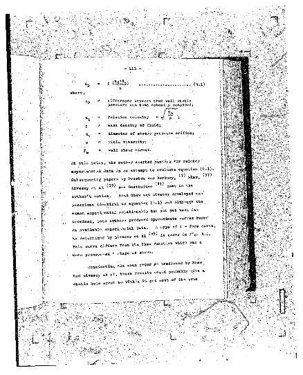
difference between true vail static pressure end that actually aeasuredj
u^ *» friction velocity
p »■ waaa density of fluid, c'-
dB " diameter of static pressure orifice}
V » fluid visedcityv .
m wall shear stress.
At this point, the author started hunting for related
i an attempt to evaluate equation (V .l ) .
(5T)experimental data i
Subsequently papers by Preston and Horbury,
L i m a r «t H 1551 «■* Ooa*h»l«*» * '7> =»»» “ « •
w t h o r 'l S o « S " " “ 8 ‘A ' o W
i d .M i c .l to c ,«»tio« t k .D » * »h .
exact r . M t i « « U r »»■ » « *** b" n * * '
t .n i n e S , ’.otl, . « » r . t ro*«a.d « , » > » > » M . . I
on available experimental data,
as deU-rnined by Livesey et al
m i . i ir t .T . » » ■ » » • »»*« ’O '1*'1 * “ ‘
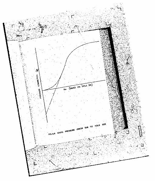
aoro pronounced S shape as saova.
« • « •* “y s“ “
results ?roX»*l»ly ci»e *
A type of Q - for* curve,
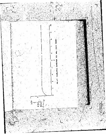
(55) i s shown in Fig* &•!*
and liivesey et b 1 , thes<
static hole error , vithin 80 Per oen* of itS trUB
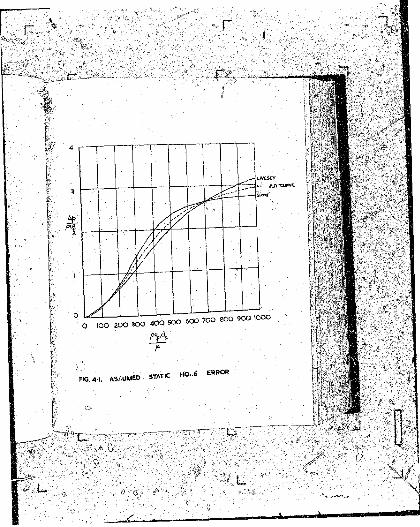
FIG, 4>J. ASSUMEDSTATIC H O ..S ERROR
0 » neftn conduit velocity*
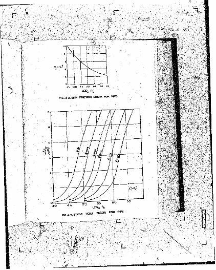
Mov Cf can be expressed in terras of ^ and the
carve representing this experimental relationship is .
shown in Fig- ^*2 . By jseana of the curves in Figa. *1.1
ana b .Z , equation (^ .3 ) can be evaluated to give the
4baverage correction factor for practical values of
at various Reynolds numbers, Shun a family of correction
curves can. be drawn as shown in Fig. fc,3.
From these results it follows that a reasonable
correction can be applied to any wall static pressure
reading* in a particular pipe, aepenainfl'on the hole sisso
and the Boynolds nu»hor, or that the » . . } . » » « l « . of »
static orifice a ia .e t .r can be aot.rMin.ll; in oraer to
attain a specified limit of accuracy, .<
It i» n . c m a r y w P»i»* » " • *>*” " • “ “ “ “
application o , correction . .t h e * a .p .na .
on c o n .i a e r .W . additional e w .r i .e a t .l there i= ,
at present, » « » . aonbt .tout t,i. . « « .hap. of the S
- + t,» or-iftin. Theoretically thecurve, especially near the origin.
sraaient of t h . cnr,e » . » « - « » « «
. u t a M .t i .t i m the presently “ *— **? * ’
** -n vve BHave of tlle curve ttear the experiments confirmed tr ^(.101 -eljorted such a wide
origin. Stratford • » * '
r
scatter near the origin that it was impossible to
determine the exact shape of the curve. Has ^ 3 J
tained a curve showing an almost linear relationship
t&is shape. The nost recent work by Livesey et al ( 55)
produced yet another curve, as shown in Pig. having
a very flat 3 shape which, in fact, approximates * flat
parabola near the origin. This part of the curve was
however obtained by extrapolating to aero hole siae in
accordance with the assumption that the static hole error
might be proportion&1 to the scan dynamic pressure in the
undisturbed flow in the boundary-layer. ' Shis hypothesis,
which still awaits rigorous corroboration, Sops not seem
unreasonable. 'V.
. (1*7)Applying this approximate S curve, Ooethuisen
ealewlated corrections for static pressure readings ia
bouadary-layer flow at high Beynolds numbers, in fully
S l o p e d flow in a pipe, and in * 6wo-di»ensional channel,
differentiating between the 'inner' or ‘ universal' and
-outer'* flow regions. The difference between a static
1,01. correction for 'inner’ an« 'outer. . .s i o n . in pipe
flov i . , however, not .p ,r .« i * t .i . TO. correction toe
Th« ‘ Inner’ or ’ universal* region is the flow zon_ .*?«* wall in which viscous shear stresses are as important •
turbulent shear stresses predominate. (
uo turbulencc, which io dealt with ,in the following
paragraph, would be different To* the two re^ione W t the
static hole correction is surely not affected by the
difference between the Velocity distributions for the
'inner* assd 'outer* reijiotis.
For determinins the shape of the 5-functioa near
the origin i& order to define its present approximate
form more precisely, the author suggests the following
experimental procedure :
Attempts to correlate experimental results on the
lines dictated by dimensional analysis is a fairly reconl
devalopnieat and should form the basis of future ex
perimental work. The sain difficulty in previous in-
yestigatiot ? seemed to be that of estimating true , static
pressure at the wall froo measurements of wall static
pressure at tapping points of various diameters., and
by extrapolation to aero hole aiae. Calculation o£ ttte
true wall static presoura from a series of accurately
determined experimental .parameters instead of e*tra-
p o l a U M iA - - gion where the are a u b ^ t to
maximum errors du« to tbi ***11 t a p in g bole sxaes,
sestts to \ia the preferable alternative. -
Sha total pressure in a boundary-layer can be
d e m i n e * fairly aceuraieiy hy me*** »f . p . « 1 ^uad.ry-
layer tot&l pressure probes. The oevly-devslojiaa
•bot-film* technique ^ 8 ) couid tJlen be a ^ i o y ^ aai ,
velocity patterns, close to a pipe voll in the ktnyxa&Ty-
loyer, could tie measured to greater accuracies than those
given by tie existing ’ hot-wire' methods. - Fioo -thece
jaeasnrea velocities the total presausa, as measured,
could p i necessary) be corrected for turbulence and the
Syjiaaic pressure head determined, from vhieit tfee true
static pressure close to the "pipe vail ooulft fee calcn- .
lated to reasonable accuracy. THis aattoft v ^ i a pro
bably yield a store reliable error function* or B-curve,
wise the uesalts are correlated vitit neasared -wall static
tapping values. Th-a error correction due to this factor
-will -be dealt -aitt again v'ben coosideritie wentnri meters
Chapter V I .
3 .3 Internal finish o- tapping hole
tola « » ! • » . * * * * * » •* * <■»
»ith « * •* » ' « « « » “ » I"1!*
„ ; i <a«o i u m u t ia th . u a r t i a u « *
M U . M i ‘-t 1* «■»* * “
M , » < » » . r r . . Sh .v tSTl « • » . » • * « » » * » “ * » «
t u t « j t o « «*«*«■> V W " *
C « t t « ttaa « « » * * » »« 'i**1*'1 * * » * « w l * ” 1**-
, « « , « » > < • ««*»«»•»- •■ », «■ »»»» «» “ * i - w * " 1
when a relatively s»all U&le siae is
used in big pipes, with Sigh roubgneas coefficients, the
internal P*Pfi wall should be smoothed immediately upstream
and downstream of a. bole. Burro -tend to shed myriads
of small eddies which, when superimposed on the asia floa
near a hole, cav^se secondary turbulence affects and in
creased error.
2be author 6ubaits that 'tapping hole manufacturing'
could he improved considerably and possibly standardised
i f plugs were made separately. This would ensure the
necessary meticulous attention to finish; these plugs
could be fitted into a pipe through a boss auoh that no
edges or burra existed between the internally prepared
pipe surface and the internal plug profile.
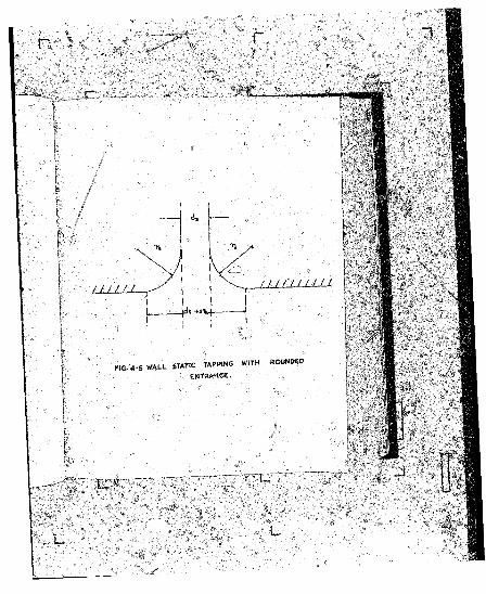
3 , it BnnadaJ internal tapping hole corners
I f the internal bole comers are rounded excessively,
secondary flow occurs in the.immediate hole entrance
causing i»^aet which tends to increase true local static
.preMsura. ' ,t
Most investigators prescribe a 'small' or
•reasonable* rounding of the internal edge vithout
t t u t i U l »■> « « « * “ .• m rk “
University (lTi •••- * to in«i««t» tl*t » ' . l w j M '
ro« ,4i»e to . » » « » • of oae-tentK' of tk„ U p f U l h«X.
Uwur i» “?la* M
choosing this particular ratio, The A .3 .M .S. Code.,
proscribes radii which apparently bare nn fixed re
lationship to hole diameter. Scale's values, as well as
those specified by the A .3.15.2. Code, seem high when
compared with the findings at Liverpool University.
Livesey et, al on 'she other hand reported th»t
a hole with radiused edge a larger error than one with
a sharp edge free from bwrrs, whereas * hole yitfc chaii-*
fsrred edge showed a r&dueed. error, Glaa.rl3 , th« effect
of this factor remain? a source .of speculation.
n, Furtlier-r-o .eareti>;al and experimental vori yould
therufore.'fes'vof considerable assistance. It would ^
■probably be advisable to select a.dsep hole;of diSaefeer,
d , and to adjust this at entranc® to a slightly Higher
value to allow for the effect of a p^ticu lar rounding
radius, r . ’She static hole aianeter to he used would
then be d| “ da + 2 rE , instead of 8*.. See Fig. *<-5 .
•T»e author* s assumed correction curve (r ig . * • !) . could
then be t«* tte ifr 'V d jw fd « i l i M d i ^ e t .r Valuer,.
9 \<m attempt to establish iH« relationship * « « « »
' 'k '^ 4 r It should be observed. However* that the
rounding » d i u . i « . in « * * « * . t0 “ inc*ease '
in static orifice diameter, and therefore these results
should he co^arcd itb those obtained t r n identical
sharp-edged orifines. I f a aore reliable static
pressure datum could bfl calculated, as proposed, the
dosbt concerning fclie error effect of this factor could
probaMy be eliminated. -
3*5. liet.boa of pressure tapping ..
Pressure can be sensed by means of s ,
3 .5 .1 A sinflla tapping point in a pipe wall;
3 .5 .2 a number of orifices distributed syauaetri-
. " colly around a pipe circumference* or
3 .J .3 pieaonetric slots or rings over tlie whole
, or part f f e pipe perineter.
litia a £1QV i s s u f f i c i e n t l y ' a t r a ifS & t ' at. s a y s e c t i o n ,
1 . . . r t .l M turtuleue. » " « ' « « * ,lt“ “ »»” »»*«
ra»e.l»s u a ifo r . «■"« « * crearvaaction,
tk . « « * 8 * * » i a pressure «*» »» »a»»ur.4 W » » < of
a. a i M l a v a i l a t r t i . o r i j i c a . t h . a a l i ~ l a o » -
d i t i o u a v e r y a a ia a w o b t a in i n p r a c t i c e .
S h o a l* t k a tw r b a le a c o l e v e l l a « « c l t t o t a c i r -
C f e r . a t i a l a t a t i e P » « * » » « v . r i . t i o . “ « “ >*
5. 5. , «ta«> »»■* “ » • » * * • * . M ia tar .in . tie beat
a „ r . 5. « ! « . of w . atatia ■ * « « « » » T « * oros,-saetio„.
Th i. « a « » l i « * * • beSt" • I * * '* * 11’™ ” “>■«“ * « ti* 14
r
r .
a. ad latoratnty application*.
'Wi'tk a view to improving average static pressure
measurements in turbulent flows, aethod 3 .5*E above is
often employed. I f , houe^er, the pressure at points
M i n o i a cireusilereacs fliffeis appreciably, circulation
through a circuaferential ring will .insult* aad aa
erroneous static pressure will t>* re/ji utered at the
* lead-off’ point in tie rinc*
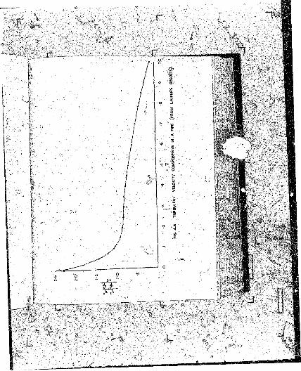
Ib the discussion on reference ( 8 ) , tfinternitz
referred to a thesis on static pressure measurement, sub
mitted to tb>/ University of GtJttiacec by KSause, dealing
vith pressure measufr'SBieKt "by means of slotted orifices,
mss results revealed that corrections were almost
negligible in the absence of a pressure eradiant ia the
direction oS flow* At a position 0.11J. fro#. ib*
leading eflse of a slot of length L. the cprre/et static
pressure was measured provided the fieynolds trattwc, ttased
. 4 . !< * « « k , w » »»*» W . » » « * » * * sl» * * 4
ot<. in tie dascaSaiaa that accurate aanttfeettire of the
«l«- typ « t » » l u * ™ » »* •»« U n i - M i»
Si r . al»o » l»»r » w t i » * * * r‘ ^ ‘ 0t
n a M r * the .lot » M » l » » * lot a ***”1"* ■»»'>“ “ f
I B . , u s 60 * « 1 4 »» » *■ » •
the *lot >aj«>»B Joe* M * ajpe»i-
' \ ■
to be without merit and further theoretical etna ex
perimental analysis seei»s justified.
3 .6 Static hole arror thto to turbulence
WUen the stream tuhes of flow in a pipe are straight
and parallel, static pressure is uniform over a normal
cross-section. I f atreau tubes are curved, however,
static pressure increases from the inside to the outside
of a curve due to the effect !ot centrifuu&l fores.
Turbulence and eddies iri a stream can 1>e considered
as a complex structure of eu)>ved currents superimposed on
the ga^eral flow pattern or raotioo, causing local
variations of static pressure ovet a pipe cross-section.
In turbulent* flow the true static pressure at a
wall static tapping would differ from that at o joint
distant y from a pipe wall. Another factor often
overlooked is the difference between the irue avsrage
Vail static pressure and the true average static
«■!* « « « • « " «
ot p r t i .u l . r l w r t * * " « • *»* “ *
upstreao Static pressure in a rar.tun meter.
The jfarier-3tokes eftuatioog, expressed in cyUndri-
»o - o r « i«M ... « • » • B U M * “ “ i* “
JmHj- developed piS* » “ > *»* " c° “ .
equation yields t
true static pressure at a point-distant
y from the pipe va.ll; }
true static pressure at vail t®Kf4»»R3 •
friction velocity,
P
*
•%FSr,y pr , where r * radius.
v* and w' « turbulent velocity
> avalwvfted tv«A .'•I This correction equatioi
« ,» « ! « • » * ' * « > •* * * * » «
( I|2) and is a two-diaaaalonal ahan-structftxr? ’u a Dip* •
, <SG. >nel.
■ IB velocity i» H . f « “ ' “ M l *
total » « ■ « . « . P ~ H » * » * 11 ■“ * “ * a W l ” ' * “
employed nor*
»» corrected f « hole
leace, the latti
Of the -total pressure pret? ^relative
:ura^ly iX the static pressure, •»«
well as for turVu-
eorraetioa depending on the jjoavtiott
the pipe vb11« ..
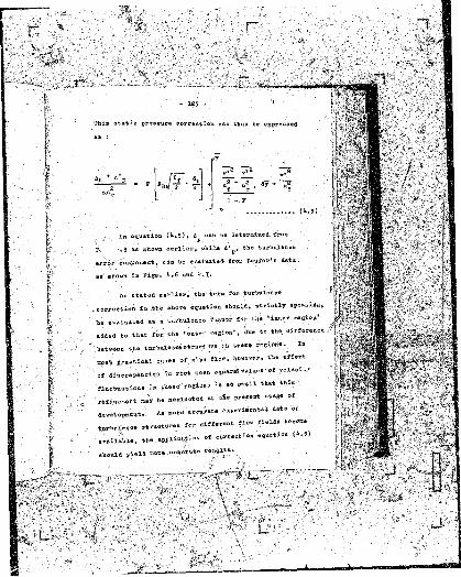
This static pressure correction can thus be expressed
/V. d.DV a D
. , In equation (fc.5)» &p can be determined from
^ . ' , 3 as sfcovn earlier, while A '^ , the turbulence
error component, can be evaluated from Laufer's data
as shown in Pise. 1».6 and l|.7«
As stated earlier, the terra for ,turbulence
..correction in the above equation should, strictly speaking,
W m l » M * ~ » » * » ,1“ V
. M . 4 to that Cor t » 'out-- - Sioa1. *™ «
between the tm-HuXeRcs Btrunt i» tfcese m rio r^ . Ia
j r .r t ia .l . . . . . 0» ptp* > ' » ' * > « " * ' • ll“
' « J i ..r .p M > r f .* i » » •* » ■ « *■ *« « *— “
t l M t » .t i o « . i » ‘ 1»>« U “ *U t’“ t “ “
W . M •“ * *l “8* "
A . » » * « " * “ “
tiirb«$ence atracti.* —
available, the aprl-
ehculd yield acne *«.
. jjpcerent flov fields become
... -f correction e la t io n (& .5 )
rtiftlta»
. r
l :
A eorrection which haf apparently been overlooked
uuvil noK is that for the average static pleasure over
a cross-section of a pipe, say, relative to tbs wall
sta«io pressure aeasurement in turbulent flovfi. At
-fcho eatrance and throat sections of a venturi meter, for
example, the static pressure^ as measured Tjv a scties..
of wall static tappings ars considered. as the average
values tor -these sections, irrespective of the variation
ot static pressure over a gipa cross-section. ;
Neglect of this correction vould, of course, affect
• experiaentolly determined ^alues of the discharge .co- ...
efficient Ca« :; ..
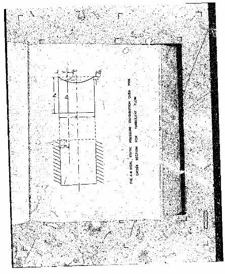
l‘he assumed ideal static pressure aUtribaiiea over
a cross-section of turbulent flov in a pipe is shown
in .Fig. ^ .8- It follows that the mean static pressure
over the cross-section is given bjr s .
— w 7, ■ ...... ..........Ps s pv - V i ■
A' represents the . ! « « « rklu. ot » • turW lcn...
n o n U a * * • pip* A‘ W
7 f . » . t * . r f w " H - «■ ' « * “ ' V
» i u 6 . i « » . k” * * " * * '•> w “
• » « » t a ; , v i .r . » ; i . « « " * » « * » « “ <*•*>• -
» « « i » . Of a ; =»■> “ « ■ « •
■ 1261 - ■ . ’ '
u
L
r ^
„r, r
- 127 -
2 li (r - J-) ily *. ^ * ™~-
■' vritins« bb "before, y * we &av«
dy ® r . dy
and hence equatioB (I|*7) TaecoaeS t
anr® ( l - y ) • ay =« a * .
■ _ -
or 1 * = * 4 ? * i u - 7> • a"y
Substituting e la t io n in equation (4 .8 ) yields s
J $ » a / ( i - r)
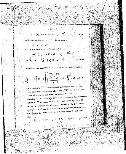
n o n Leufer’ s ^ w * ! — * * a e t e r m i ^ i ™ • * ^
, valu- « * ^ * «root txean
loped pipe flow, the
equation i ' e- ap* ttflTe
- „„ „ „ in Pis. ‘•-1 ana J»«nce -A* U ~ V* values of y -B8 a*0* 11 10 * 1S* p
oa« be determined tor different
u „„ . . . . . « ™ » « “ w
tTae
*•«*[(. in square brackets an
teen evaluates t*t aifferent
and hence^-A tl ~ 3^
_ values of 7 , fro* vhf.ch
( it. 9) can l>e
, .BliOWn i» * ' 9 frow wHich l* <
1.26 . T# C
~ ~ r - r r — - « ^
f e '
, dy
;{1*.10)
1 - 7
Thus Ts© dafcerniijed for ■a psrticalRr
friction r*l>. Ity tjf end from equation {*>.6) the tree ave
rage static pressure over s pipe cross-section under
conditions of turbulent flow can be estimated:.
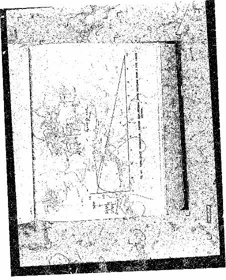
The foregoing discussion reveals how tt>c Ai¥x'erenfcia.l
pressure measurement in a. venturi meter is affected. 1 XJ"«
as a first approximation, the turbulence structures in
the throat and at entrance to a venturi neter ar* asssaed
to Se approximately of the same fora, the constant, C,
in equation {li.10} would be identical for the entrance .
afi& thro&t>sectinasi _
TJ'ua ;
(throat) * CT’ , and .
A* {entrance} = c ^
The need for corrections would therefore. n °* be elimi-
nate/J vhen a pressure difference iz considered because
*i>« or i . »»a r ; .t ti™ t » o ..c t i o m w *
Stta . « . V t of O k corr.otioo U « th .orrtio .l « * * " » * * »
for o . O M U & i « » * * « « « " * • * * ” *"■ * , 'U " *
dealt with in Chapter VI- ~ «
' .-’ to „ t « M d « » Z l « r , evaluation * f J a w * * ™
correction* is possible only i f x H i .V a *
squared values of the 'sraioeity flue-
4>
tuatioas m var
are available*
■ I
o •
' I J f f f V
' • - X
iate turbulent flow rej
~!
• - 1 0 '
L.MiFiCEe.iij.j
san slew be Bwasured by correctly
sies or cjfliaSrioal tubes. I f
is correctly oriented in a flov
cis being either parallel or per
pendicular to the direction of flov - total pressure will
he registered at the stagnation point. 6 study of the
pressure distribution around such bodies reveals that
somewhere between tiie stagnation point and the negative
or suction pressure sone a 'neutral position* ejciutB
vhere a email orifice would resister, approximately, tie
static pressure in the fluid ; this position is approxi
mately 1(0 degrees from the t
nd tube held vith
t of fluid motioa 1
,ure. In practice
Theoretically»
pe-rpeadicular to the
register the tr\
' I * . I l n i i <vs.™ rM .O T . J « « « • O S« » i» S ,
1 . flow lines at **A within the
etion. On the
alt from within
hut actually forai
opening, thereby ■
isnd, a prai
' d * ~ X r
correct positioi
n
L.
of flow at the particular p»int, therefore, does not
eolT«.the probleiu
The factors affecting static pressure measurement
by suitable orifices on spherical or cylindrical probea,
can be listed as :
U .l The error due to inappropriate sise of orifice;
6 .2 the shift of the, neutral position on the probe
bodiy with increased Reynolds number} . .
It,3 Misalignment of probe vith direction of flow;
l».lt the boundary-layer formed on the probe itself-,
lt. 5 the effect of turbulence.,
u .l Tna-nnropriate orifice size :
• Just ftS the presence of a small pieaoaet«r hole in
a pipe * * 1 1 causes an error in a vail Static pressure
.0 1 . . i, W . I . . « • « 1* « «
W n , i < t U » i « »» « * » « » » * » » * •
t U t t h . . t « J « M ‘
i» tu« flow in f - e o u i w r - i w ' ° » ' rdb* ' “
i d m t W to . , « . t i . « ( » • « «“ “
r
r
vhere = static pressure error due to the Static- P
hole size; on a probe, and .
dP » diameter of static hole, the other symbols .
having their usual meanings.
to evaluate equation If.11 requires experimental in-
last&itxtion*. The total pressure in the probe boundary-
layer must first be determined by means of a miniature
total pressure probe. Sy ’ hot—film' technique, velocity
profiles close to the probe face could be surveyed and
from these the static pressure could be calculated. By
correlating the calculated with the measured probe values,
. an error curve could probably be constructed to eive
the pyobe static hole orror for a particular instrument.
HoWhere i n literature 'ha this subject could the author . .
find any evidence of attention to this factor.
The shift of the nautral -position .
The position of the Neutral point* on a spherical
or a cylindrical f . ~ i« ■ « * la t " ' “ “ ,f l “ w
from t b stagnation V * r * •> « • • « " > » « • »»*“ ' 1»*
e r«a m «. Thi3 «a«««B ov=r-r.si»tr»tio» of static
P„ . . « r . b . . . . . . t l . fo .it iv . pressure w »»ve= . . .
- 131
P
F
T B .4-10 E RROR CURVSS FOB BBABBE AND PRANOTL TUBES
' U
fteyaol&B nunber Ta&ges, the '• neutral point1 also tends
to oscillate about fee position of the static orifices,
"Ehe degree of -shift, qt oscillation is noefc p*-vbably
controlled "by the tnrbulence level, and could be caused
by the complex interchange t>f energy between the laminar
sab-layer and the turbulent boundary-layer on the probe.
A fons of boundary—layer control could perhaps aijiiaiae
this e ffect , but. such an approach voald probably ?oaa .
more difficulties than it solved. This factor will
apparentXy always preseat an Jlobatacle to static pressure
aeasurenent. ■
b .3 Probe alignment
On* of the uain sources of error results from the
A i H K m M r associated with • t » b « » e m *«t .lr
»iM> « . dir.ctioo of «1<~. n i M is m a x « !« »
tie » M » 1 « J B r«bW M » . « « » " « * *» » *“ “
w piosom trio klot2 • « positioned oo a oylinirictil take
k M i w its * *is parallel to 1 U n o * direction
I f the instrument is inserted into a flov field ,
»t an - 1 1 = of » * * « ' * “
m U M r »»«*>«>■« I 1” * * «“ »"■ »•* “ r 1‘-*
* « . * .M * »“ * «■• e l *s i ': “ ” ** r °r
tie Prandtl « d » . « * ' » « * • » * “
■ pC :' ................ ......-..
- 133 -
approximately identical sensitivity characteristics
for angles of flow direction, the error being about ::
-5 per cent at ayt ansle of attQck of" _+ 15 degrees. The .
limitations of these instruments when nigh accuracies are
required, in two- and three-dimensional flow fields,
are therefore self-evident.
b.ii ghe probe boundary-layer
The formation of a boundary-layer on a probe vould
affect the registr-fcioa of static pressure. I t , aa
was assumed* the static hole error is caused by u. dis
turbance of the flow in the boundary-leyer and i f the
£TDb% boundary-layetf controls the shift of the ’ neutral
point’ , this effect should be studied in detail by means
of total pressure and velocity traverses. The effect on
static pressure measurement of boundary-layer growth,
Stability and flow *}as not received the necessary - .
• attention and although the experimental obstacles
with such an in s t i g a t io n would be c w .id .r a M * ,
a £un<L*maIa a l study Qt this lutur* sea** to be essential.
■fc.5 Ttee effect of turbulence '
I f a pitot-atstic t»be ia a l ip e d vith the main
Of t u v in . W > b «l .»t « » » • ■ * » * '
f t a «t « .t lM velocity component »o ,ld »«t . « * « t *
static pre.eurt » * « = * • « » * ' “ « » ’
' L .
r
r-
- 13*
tend to inorease the static pressure, depending on
the actual flow directions of these turbulent components
at the position of the static orifices. Expressed
mathoB&tically,,
K.p v»
vbera. i4 = static pressure error due to turbulence,P
. , aa^
4 constant to be determined depending on
• tlie directions of the tufbulejjt flue-
tuating velocities. . - •
. ft rigorous nathenatieal formulation of this effect
is aot yat possible, but-PoKa (595 susseated tfeat a.probe
would overregister static pressure by an ano.uot ,
■L, I in a turbulent flos field.
Ihus e la t io n U .1 2 ) can be vriVte.
V
In sugeested t*e aliove value *f
s = 0 .2 5 ana. to the author'a fcnt-vladgo, no further
attention was given to tbis factor.
r
r
Sq.uati.oa U .1 3 ) be written. as s
**72 ”
replacing Pass's constant of 0.25 by Kt . •
Instead of separating the static pressure error
due -to orifice siae ,nn4 tuvbulenee - the former would
be very difficult to evaluate as pointed out earlier -
one could perhaps consider the inherent orifice size
error as being related to turbulence structure, and
revrite equation ( I ; .!1*) in the form ? -
u“pK . . (* .1 5 ) .
where K is a correction constant and ftp is 'fcbe total
static pressure error i .e . due to turbulence and orifice
s iie . , ■ ••
From Laufer's dt&a a curve t&b be constructed
4 in terms of y, where y
as bsfore.
K „ „ 1 , . v . M . M a t r o . . r a t i o n ( * . 15 ) T o r P -
ai-tione y . B u m , U>. • * * » ' * » » « * * « » " m "
rt .ay' a joint ~ i » » » • " » «*“ '
by u .in s a v a n static tapjins and oorr.etioB «■
i determined
r
u,pK
arid.ot < W if Up i« * « " > * “ *

Author Hopkins DName of thesis Some Recent Contributions To Fluid Flow Measurement And Instrumentation. 1964
PUBLISHER:University of the Witwatersrand, Johannesburg
©2013
LEGAL NOTICES:
Copyright Notice: All materials on the U n i v e r s i t y o f t he W i t w a t e r s r a n d , J o h a n n e s b u r g L i b r a r y website are protected by South African copyright law and may not be distributed, transmitted, displayed, or otherwise published in any format, without the prior written permission of the copyright owner.
Disclaimer and Terms of Use: Provided that you maintain all copyright and other notices contained therein, you may download material (one machine readable copy and one print copy per page) for your personal and/or educational non-commercial use only.
The University o f the W itw atersrand, Johannesburg , is not responsible for any errors or omissions and excludes any and all liability for any errors in or omissions from the information on the Library website.