r-series models rp/rh - analog - mts sensors · r-series models rp and rh analog sensors provide...
TRANSCRIPT

MTS Sensors 7 Temposonics® Linear-Position Sensors Product Catalog 551075 C
R-S
erie
s An
alog
R-Series Models RP and RH Sensors - Analog OutputPosition, Speed, Speed with Direction
Single or Dual-Magnet Positions
n Rugged industrial sensorn Linear, absolute measurementn LEDs for sensor diagnosticsn Non-contact sensing technologyn Non-linearity less than 0.01%n Repeatability within 0.001%n Direct Analog output, displacement + speedn Dual magnet position measurementn 100% field adjustable Null and Span setpoints
Operating conditions: - 40 °C (-40 °F) to 75 °C (167 °F)Relative humidity: 90% no condensationTemperature coefficient: < 30 ppm / °C Setpoint adjustment, (Null/Span): 100% of electrical stroke length. Min. 25 mm (0.98 in.) distance between setpoints. For dual magnet outputs: Min 76 mm (3 in.) distance between magnets.
EMC test: Emissions IEC/EN 50081-1, Immunity IEC/EN 50082-2, IEC/EN 61000-4-2/3/4/6, level 3/4 criterium A, CE qualified
Shock rating: 100 g (single hit)/IEC standard 68-2-27 (survivability)
Vibration rating: 15 g (30 g with HVR option)/ 10-2000 Hz/IEC standard 68-2-6
Connection type: 6-pin male D60 connector or integral cable
PROFILE STYLE (MODEL RP) SENSORElectronic head: Aluminum housing
Diagnostic display (LED’s located beside connector/cable exit)
Sealing: IP 65Sensor extrusion: AluminumMounting: Adjustable mounting feet or T-slot nut (M5 threads)
in base channelMagnet type: Captive-sliding magnet or open-ring magnet
ROD STYLE (MODEL RH) SENSORElectronic head: Aluminum housing
Diagnostic display (LED’s located beside connector/cable exit)
Sealing: IP 67 or IP 68 for integral cable modelSensor rod: 304L Stainless steelOperating pressure: 350 bar static, 690 bar peak
(5000 psi static, 10,000 psi peak)Mounting: Any orientation, threaded flange M18 x 1.5 or
3/4-16 UNF-3ATypical mounting torque: 45 N-m (33 ft. - lbs.)Magnet type: Ring magnet, open-ring magnet or magnet float
Measured variables: Displacement, speed (magnitude), or velocity (with direction) for single or dual magnets
Resolution: Position measurement: 16 bit; 0.0015% (minimum 1 µm)Speed measurement: 0.1 mm/s
Non-linearity: < ± 0.01% full stroke (minimum ± 50 µm)Repeatability: < ± 0.001% full stroke (minimum ± 2.5 µm)
Hysteresis: < 4 µmOutputs: Voltage: 0 to 10, 10 to 0, -10 to +10, +10 to -10 Vdc
(minimum controller load >5k ohms)Current: 4(0) to 20 mA, 20 to 4(0) mA, (min./max. load 0/500 ohms)
Stroke length: Profile style: 50 mm (2 in.) to 5080 mm (200 in.)(Position MeasurementRod style: 50 mm (2 in.) to 7620 mm (300 in.)Range) Update time: 0.5 ms up to 1200 mm, 1.0 ms up to
2400 mm, 2.0 ms up to 4800 mm, 5.0 ms up to 7620 mm stroke length.
Speed measurement: Range: 0.025 - 10 m/s (1.0 - 400.0 in./s)Deviation: <0.5%Resolution: 0.1 mm/s (0.004 in./s)Update time: See position measuring range
Operating voltage: +24 Vdc nominal: -15 or +20% Polarity protection: up to -30 VdcOvervoltage protection: up to 36 VdcCurrent drain: 100 mA typicalDielectric withstand voltage: 500 Vdc (DC ground to machine ground)
Parameters Specifications (continued)
Parameters Specifications
R-SERIES MODELS RP/RH - ANALOG

Temposonics® Linear-Position Sensors Product Catalog 551075 C MTS Sensors8
R-S
erie
s An
alog
Enhanced monitoring and diagnostics
Sensor status and diagnostic display
Integrated LEDs (green/red) provide basic visual feedback for normal sensor operation and troubleshooting.
LED’s
Green Red Description
ON OFF Normal function (operation mode)
ON Flashing Magnet out of setup range
ON ON Magnet not detected or wrong quantity of magnets
Flashing ON Programming mode
Outputs
Single magnet sensor
Dual magnet sensor
M1 M1aActive stroke length(Position measuring range)
Position / Speed
M1 M2 M1a M2a
0 Vdc
10 Vdc0 Vdc
10 Vdc
0% 100%Position 1 / Position 2
76 mm min.(3 in.)
R-Series Models RP and RH analog sensors provide single or dualmagnet sensor options along with one or two channel outputs.
The R-Series analog sensor can be ordered for a single-positionmagnet providing one displacement output, and/or one velocity output over the active stroke length.
The sensor can also be ordered for dual-position magnets providingtwo displacement outputs, or two velocity outputs, or one of each.
When using dual magnets, the minimum allowed distance betweenthe magnets is 3.0 in. (76 mm) to maintain proper sensor output.
R-SERIES ANALOG SENSOR OUTPUT OPTIONS
Sensor field programming
R-Series Model RP and RH Analog sensors are preconfigured at the factory by model number designation. For many applications, noadjustments are required for normal sensor installation and opera-tion. If, however, sensor parameter changes are needed while in thefield, the R-Series Analog sensor is easily programmed externally.There is no need to open the sensor’s electronic housing.
R-Series Analog PC Programming kit, part no. 253309For single or dual magnet sensors
This programming kit includes a wall adapter style power supply,serial converter box, two connection cables (wired for the LIN proto-col), and the software CD-ROM. The serial converter box and one ofthe cables are required to communicate between a Windows PC andthe sensor. When running the R-Series Analog PC Setup softwaremany customized settings are possible for:
• Setpoint 1 (Null) and Setpoint 2 (Span) for single or dual magnets. (See the description for setpoints under the section,
“R-Series Analog Handheld Programmer”.)• Output range settings for speed, or for speed with direction.• Assign position or velocity output functions for the single or dual
magnets, and for the one or two output channels. (Output function assignments are limited to the manufacturing build type of the sensor, see below.)
• Error output values when the magnet moves beyond the programmed setpoints.
Field programming is available to adjust the output values for anysetting needed, within the selected output range. Each sensor’s out-put range is selected from the available options when ordering aparticular sensor model number, (see pages 7 and 8).
There are 6 different manufacturing build types used to provide forthe various output ranges. These are:
Single Channel Output for either position or speed1) Voltage output between 0 and +10 volts 2) Voltage output between -10 and +10 volts3) Current output between 0 (or 4) and 20 mA
Two Channel Outputs for position and/or speed 4) Voltage outputs between 0 and +10 volts 5) Voltage outputs between -10 and +10 volts6) Current outputs between 0 (or 4) and 20 mA
ADVANCED COMMUNICATION AND PROGRAMMABILITY
Note:Field programming allows for numerous custom sensor configurations,however, please note that field programming can not be used to change theR-Series Analog sensor from one manufacturing build type to another.
MTS Sensors 9 Temposonics® Linear-Position Sensors Product Catalog 551075 C
R-S
erie
s An
alog
CONNECTIONS AND WIRING
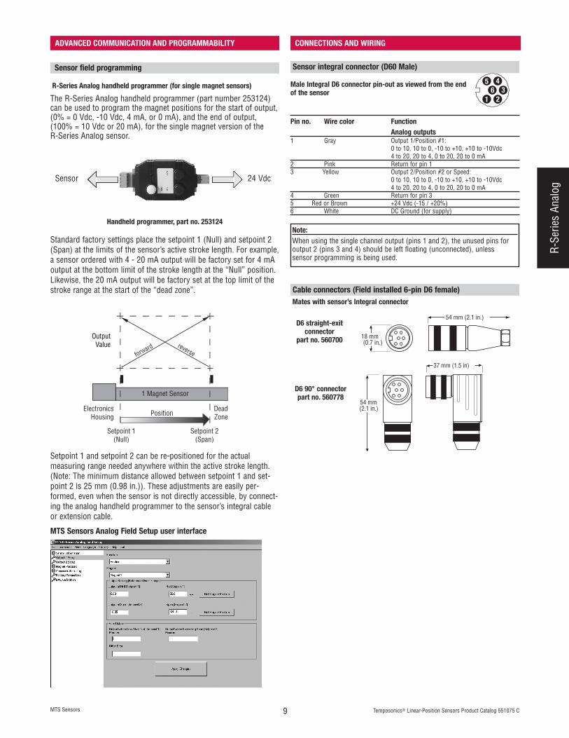
R-Series Analog handheld programmer (for single magnet sensors)
MTS Sensors Analog Field Setup user interface
Handheld programmer, part no. 253124
The R-Series Analog handheld programmer (part number 253124)can be used to program the magnet positions for the start of output,(0% = 0 Vdc, -10 Vdc, 4 mA, or 0 mA), and the end of output,(100% = 10 Vdc or 20 mA), for the single magnet version of the R-Series Analog sensor.
Standard factory settings place the setpoint 1 (Null) and setpoint 2(Span) at the limits of the sensor’s active stroke length. For example,a sensor ordered with 4 - 20 mA output will be factory set for 4 mAoutput at the bottom limit of the stroke length at the “Null” position.Likewise, the 20 mA output will be factory set at the top limit of thestroke range at the start of the “dead zone”.
Setpoint 1 and setpoint 2 can be re-positioned for the actual measuring range needed anywhere within the active stroke length.(Note: The minimum distance allowed between setpoint 1 and set-point 2 is 25 mm (0.98 in.)). These adjustments are easily per-formed, even when the sensor is not directly accessible, by connect-ing the analog handheld programmer to the sensor’s integral cableor extension cable.
OutputValue
OutputValue
forward reverse
1 Magnet Sensor
Setpoint 1(Null)
Setpoint 2(Span)
PositionElectronics
HousingDeadZone
Sensor field programming
Cable connectors (Field installed 6-pin D6 female)
18 mm(0.7 in.)
54 mm (2.1 in.)
54 mm(2.1 in.)
37 mm (1.5 in)
D6 straight-exit connector
part no. 560700
D6 90° connectorpart no. 560778
5 436
21
Pin no. Wire color Function Analog outputs
1 Gray Output 1/Position #1:0 to 10, 10 to 0, -10 to +10, +10 to -10Vdc 4 to 20, 20 to 4, 0 to 20, 20 to 0 mA
2 Pink Return for pin 1 3 Yellow Output 2/Position #2 or Speed:
0 to 10, 10 to 0, -10 to +10, +10 to -10Vdc 4 to 20, 20 to 4, 0 to 20, 20 to 0 mA
4 Green Return for pin 3 5 Red or Brown +24 Vdc (-15 / +20%)6 White DC Ground (for supply)
Male Integral D6 connector pin-out as viewed from the endof the sensor
Sensor integral connector (D60 Male)
Mates with sensor’s Integral connector
Note:When using the single channel output (pins 1 and 2), the unused pins foroutput 2 (pins 3 and 4) should be left floating (unconnected), unless sensor programming is being used.
ADVANCED COMMUNICATION AND PROGRAMMABILITY
Sensor 24 Vdc
Temposonics® Linear-Position Sensors Product Catalog 551075 C MTS Sensors10
R-S
erie
s An
alog
MODEL RP PROFILE-STYLE SENSOR
MODEL RH ROD-STYLE SENSOR
Beginning of stroke - Null positionCaptive-sliding magnet
14.5 mm(0.57 in.)
Mounting foot 12 mm(0.47 in.)
75 mm(2.95 in.)
12 mm (0.47 in.)49 mm(1.92 in.)
45 m
m(1
.77
in.)
2 m
m.
(0.0
7 in
.)
9.5
mm
(0.3
7in
.)
5.5 mm (0.21 in.) dia.for M5 or #10 Screw
68 mm (2.67 in.)50 mm (1.96 in.)
35.6 mm(1.4 in.)
66 mm(2.6 in.)
Stroke length Dead zone
28 mm(1.1 in.)
Sensor head
Mounting support (non-ferrous material)
Open ring magnet Beginning of stroke - Null Position
Sensor head
28 mm(1.1 in.)
22 mm(0.86 in.)
28 mm(1.1 in.)
Captive-sliding magnet
Open-ring magnet
D60 connector option
R05 integral cable option
The profile-style (model RP) sensor offers modular construction, flexible mounting configurations and easy installation.
LED window
44 mm(1.7 in.)
68 mm (2.7 in.) 51 mm(2 in.)
Integralconnector
Beginning of stroke (Null position) End of stroke
Electronics housingNull zone
Stroke length
Flat-faced flange
A Sensor rod
10 mm (0.39 in.) dia.
25 mm(0.98 in.)
Dead zoneStroke dependent
refer to chart below
M4 x 59 mmButton-head hex screws (2X)
O-Ring
B
68 mm (2.7 in.)
A
Raised-face flange
Grounding lugMating connector(6-pin DIN style)
25 mm(0.98 in.)
25 mm (1 in.)
51 mmBeginning of stroke (Null position)
Null zoneO-Ring
C
76 mm (3 in.) (2 in.)
2.5 mm (0.1 in.)
The rod-style (model RH) sensor offers modular construction, flexible mounting configurations, and easy installation. It is designed for internal mounting inapplications where high pressure conditions exist, (5000 psi continuous, 10,000 psi spike), such as hydraulic cylinders. The Model RP sensor may also bemounted externally in many applications.
Stroke-dependent Dead ZonesStroke length Dead zone50 mm (2 in.) - 5000 mm (197 in.) 63.5 mm (2.5 in.)5005 mm (197.1 in.) - 7620 mm (300 in.) 66 mm (2.6 in.)
Housing styleFlange type Description
AFlange threads
BDimensions
CDimensions
T US customary threads with raised-face flange 3/4”-16 UNF-3A 44.5 mm (1.75 in.) 51 mm (2 in.)S US customary threads with flat-faced flange 3/4”-16 UNF-3A 44.5 mm (1.75 in.) 51 mm (2 in.)M Metric threads with flat-faced flange M18 x 1.5 46 mm (1.81 in.) 53 mm (2.1 in.)
Note:See page 58 for installed magnet dimensions.
Note:See page 59 for mounting and magnet details.
MTS Sensors 11 Temposonics® Linear-Position Sensors Product Catalog 551075 C
R-S
erie
s An
alog
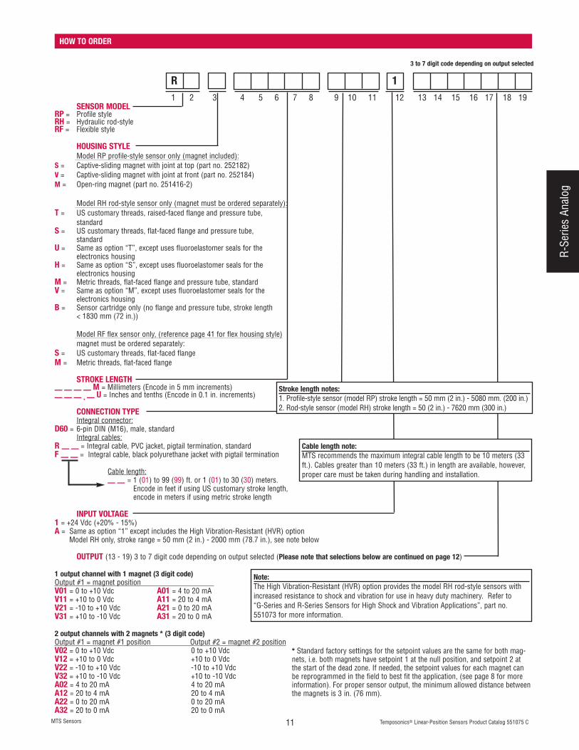
HOW TO ORDER
SENSOR MODELRP = Profile styleRH = Hydraulic rod-styleRF = Flexible style
HOUSING STYLEModel RP profile-style sensor only (magnet included):
S = Captive-sliding magnet with joint at top (part no. 252182)V = Captive-sliding magnet with joint at front (part no. 252184)M = Open-ring magnet (part no. 251416-2)
Model RH rod-style sensor only (magnet must be ordered separately):T = US customary threads, raised-faced flange and pressure tube,
standardS = US customary threads, flat-faced flange and pressure tube,
standardU = Same as option “T”, except uses fluoroelastomer seals for the
electronics housingH = Same as option “S”, except uses fluoroelastomer seals for the
electronics housingM = Metric threads, flat-faced flange and pressure tube, standardV = Same as option “M”, except uses fluoroelastomer seals for the
electronics housingB = Sensor cartridge only (no flange and pressure tube, stroke length
< 1830 mm (72 in.))
Model RF flex sensor only, (reference page 41 for flex housing style)magnet must be ordered separately:
S = US customary threads, flat-faced flangeM = Metric threads, flat-faced flange
STROKE LENGTH— — — — M = Millimeters (Encode in 5 mm increments)— — — . — U = Inches and tenths (Encode in 0.1 in. increments)
CONNECTION TYPEIntegral connector:
D60 = 6-pin DIN (M16), male, standardIntegral cables:
R — — = Integral cable, PVC jacket, pigtail termination, standardF — — = Integral cable, black polyurethane jacket with pigtail termination
Cable length:— — = 1 (01) to 99 (99) ft. or 1 (01) to 30 (30) meters.
Encode in feet if using US customary stroke length, encode in meters if using metric stroke length
INPUT VOLTAGE1 = +24 Vdc (+20% - 15%)A = Same as option “1” except includes the High Vibration-Resistant (HVR) option
Model RH only, stroke range = 50 mm (2 in.) - 2000 mm (78.7 in.), see note below
OUTPUT (13 - 19) 3 to 7 digit code depending on output selected (Please note that selections below are continued on page 12)
1 output channel with 1 magnet (3 digit code)Output #1 = magnet position V01 = 0 to +10 Vdc A01 = 4 to 20 mAV11 = +10 to 0 Vdc A11 = 20 to 4 mAV21 = -10 to +10 Vdc A21 = 0 to 20 mAV31 = +10 to -10 Vdc A31 = 20 to 0 mA
2 output channels with 2 magnets * (3 digit code)Output #1 = magnet #1 position Output #2 = magnet #2 positionV02 = 0 to +10 Vdc 0 to +10 VdcV12 = +10 to 0 Vdc +10 to 0 VdcV22 = -10 to +10 Vdc -10 to +10 VdcV32 = +10 to -10 Vdc +10 to -10 VdcA02 = 4 to 20 mA 4 to 20 mAA12 = 20 to 4 mA 20 to 4 mAA22 = 0 to 20 mA 0 to 20 mAA32 = 20 to 0 mA 20 to 0 mA
Stroke length notes:1. Profile-style sensor (model RP) stroke length = 50 mm (2 in.) - 5080 mm. (200 in.)2. Rod-style sensor (model RH) stroke length = 50 (2 in.) - 7620 mm (300 in.)
Cable length note:MTS recommends the maximum integral cable length to be 10 meters (33ft.). Cables greater than 10 meters (33 ft.) in length are available, however,proper care must be taken during handling and installation.
3 to 7 digit code depending on output selected
1 2 3 4 5 6 7 8 9 10 11 12 13 14 15 16 17 18 19
1R
* Standard factory settings for the setpoint values are the same for both mag-nets, i.e. both magnets have setpoint 1 at the null position, and setpoint 2 atthe start of the dead zone. If needed, the setpoint values for each magnet canbe reprogrammed in the field to best fit the application, (see page 8 for moreinformation). For proper sensor output, the minimum allowed distance betweenthe magnets is 3 in. (76 mm).
Note:The High Vibration-Resistant (HVR) option provides the model RH rod-style sensors withincreased resistance to shock and vibration for use in heavy duty machinery. Refer to“G-Series and R-Series Sensors for High Shock and Vibration Applications”, part no.551073 for more information.

Temposonics® Linear-Position Sensors Product Catalog 551075 C MTS Sensors12
R-S
erie
s An
alog
HOW TO ORDER (CONTINUED)
OUTPUT (13 - 19) 3 to 7 digit code depending on output selected (Please note that selections below are continued from the previous page)
2 output channels with 1 magnet (7 digit code, fill in the blanks with the desired maximum speed value as described below)Output #1 = magnet position Output #2 = speed magnitude V01 — — — — = 0 to +10 Vdc +10 (towards head) 0 (at rest) +10 (towards tip) VdcV11 — — — — = +10 to 0 Vdc +10 (towards head) 0 (at rest) +10 (towards tip) VdcA01 — — — — = 4 to 20 mA 20 (towards head) 4 (at rest) 20 (towards tip) mAA11 — — — — = 20 to 4 mA 20 (towards head) 4 (at rest) 20 (towards tip) mA
Output #1 = magnet position Output #2 = Velocity (speed with direction) V41 — — — — = 0 to +10 Vdc 0 (towards head) 5 (at rest) +10 (towards tip) VdcV51 — — — — = +10 to 0 Vdc +10 (towards head) 5 (at rest) 0 (towards tip) VdcV61 — — — — = 0 to +10 Vdc -10 (towards head) 0 (at rest) +10 (towards tip) VdcV71 — — — — = +10 to 0 Vdc +10 (towards head) 0 (at rest) -10 (towards tip) VdcV81 — — — — = -10 to +10 Vdc -10 (towards head) 0 (at rest) +10 (towards tip) VdcV91 — — — — = +10 to -10 Vdc +10 (towards head) 0 (at rest) -10 (towards tip) VdcA41 — — — — = 4 to 20 mA 4 (towards head) 12 (at rest) 20 (towards tip) mAA51 — — — — = 20 to 4 mA 20 (towards head) 12 (at rest) 4 (towards tip) mA
Output #1 = magnet position (forward-acting) Output #2 = magnet position (reverse-acting)V03 = 0 to +10 Vdc (3 digit code) +10 to 0 Vdc
For sensor models with speed output, fill in the blanks for the desired maximum speed value as shown below.For US customary stroke lengths, encode speed for in./s as follows:— — — — = Speed output max. (fill in remaining 4 blanks with desired max. speed value)Available range for US customary stroke lengths is 1.0 to 400.0 in./s, (0010 … 4000)Example: For max. speed of 12.0 in./s, and output produced =
[-10(towards head) … 0(at rest) … +10(towards tip) Volts] Encode: V 6 1 0 1 2 0 or V 8 1 0 1 2 0
For metric stroke lengths, encode speed for m/s (range 1) or mm/s (range 2) as follows:Speed range #1, ( 0 )0 = Speed output max. (fill in the remaining 3 blanks with desired max. speed value)Speed range 1 for metric stroke lengths is 0.1 to 10.0 m/s, (0001 … 0100)Example: For max. speed of 5.5 m/s, and output produced =[+10(towards head) … 0(at rest) … +10(towards tip) Volts], Encode: V 0 1 0 0 5 5
Speed range #2, ( 1 )1 = Speed output max. (fill in remaining 3 blanks with desired max. speed value)Speed range 2 for metric stroke lengths is 25 to 90 mm/s, (1025 … 1090)Example: For max. speed of 50 mm/s, and output produced =[4(towards head) … 12(at rest) … 20(towards tip) mA], Encode: A 4 1 1 0 5 0
Field programming notes:1) Sensor models ordered with one output channel can not be reprogrammed in the field to provide a second output channel.2) Sensor models ordered with positive only output voltages can not be reprogrammed in the field to include negative output voltages.3) Sensor models ordered with both positive and negative output voltages can be reprogrammed in the field for positive only voltages, or negative only
voltages, however, output resolution is then reduced.
— — — —
— — — —
— — — —
— — — . —— — — . —
— — — —— — — —
— — — —
3 to 7 digit code depending on output selected
13 14 15 16 17 18 19