r e p o r t s with notes -...
TRANSCRIPT

M A T E R I A L S
L A B O R A T O R Y
FOR ARCHITECTS:
R E P O R T S
WITH NOTES

M A T E R I A L S
L A B O R A T O R Y
FOR ARCHITECTS:
R E P O R T S
WITH NOTES

This page is left blank

Contents
Contents ___________________________________________________ 4
Preface____________________________________________________ 6
Report Preparation ___________________________________________ 7
Experiment Report (01) ________________________________________ 9 Total Moisture Content ___________________________________________________ 9
(ASTM C 566 ─ 84) ______________________________________________________ 9
Experiment Report (02) _______________________________________ 14 Specific Gravity and Absorption of Coarse Aggregate _________________________ 14
(ASTM C 127 ─ 88) _____________________________________________________ 14
Experiment Report (03) _______________________________________ 18 Specific Gravity and Absorption of Fine Aggregate ___________________________ 18
(ASTM C 127 ─ 88) _____________________________________________________ 18
Experiment Report (04) _______________________________________ 22 Unit Weight and Voids of Coarse Aggregates in Its Compacted Condition ________ 22
(ASTM C 29 / C 29M ─ 07) _______________________________________________ 22
Experiment Report (05) _______________________________________ 26 Sieve Analysis of Fine & Coarse Aggregates _________________________________ 26
(ASTM C 136 ─ 84a) ____________________________________________________ 26
Experiment Report (06) _______________________________________ 34 Unit Weight of Fresh Concrete ____________________________________________ 34
(ASTM C 138 ─ 81) _____________________________________________________ 34
Experiment Report (07) _______________________________________ 37 The Slump of Hydraulic Cement Concrete __________________________________ 37
(ASTM C 143 ─ 89a) ____________________________________________________ 37
Experiment Report (08) _______________________________________ 41 Production of Concrete Specimens _________________________________________ 41
(ASTM C 31 ─ 84) ______________________________________________________ 41
Experiment Report (09) _______________________________________ 43 Density of Hardened Concrete ____________________________________________ 43
(ASTM C 642 ─ 13) _____________________________________________________ 43
Experiment Report (10) _______________________________________ 44 The Compressive Strength of Cubic Concrete Specimens ______________________ 44
(BS 1881: Part 116: 1983) ________________________________________________ 44
Experiment Report (11) _______________________________________ 51 Destructive Test (Core Test) ______________________________________________ 51

(C 42 / C 42M ─ 04) _____________________________________________________ 51
Experiment Report (12) _______________________________________ 54 Steel Tensile Test _______________________________________________________ 54
(ASTM A 370 ─ 03a) ____________________________________________________ 54
Experiment Report (13) _______________________________________ 59 Steel Bend and Re-bend Test ______________________________________________ 59
(ASTM E 290 ─ 14) _____________________________________________________ 59
Experiment Report (14) _______________________________________ 61 Tiles Tests _____________________________________________________________ 61
(PS-13: March 1997) ____________________________________________________ 61

Preface
At the field of civil engineering, there are various tests of the investigation
of materials and methods that can be used to satisfy the needs of the requirements
for a project. For example, shelter is provided for through housing; dwellings are
built in accordance with a method that is appropriate for the material selected,
the method of construction changing with the material.
A step-by-step reports guide on the basic tests performed in Materials
Laboratory. Testing supports procedural steps and demonstrates specific
standards. It also covers how to properly present data and a report document,
containing numerical examples and figures. The information presented is based
on different adopted specification codes, such as the American Society for
Testing and Materials (ASTM) standards, the British Standards (BS), and the
Palestinian Standards (PS). Furthermore, this PDF deck demonstrates fourteen
different laboratory tests that an Architect should be aware of them, and grasp
each one comprehensively.
Engr. Yasser M. Almadhoun
Civil Engineering

Fall 2016 MATERIALS LABORATORY FOR ARCHITECTS: REPORTS WITH NOTES
ENGR. YASSER M. ALMADHOUN | MATERIALS LABORATORY FOR ARCHITECTS: REPORTS WITH NOTES 7
Report Preparation
The report should consist of the following two parts:
(1) Cover Page:
An example will be shown in a single page.
(2) Report Contents:
Objective
A brief statement of the purpose and significance of the test should be
indicated.
Apparatus
Special equipment used should be briefly described “may include
photos”.
Procedures
The testing procedures should be described as points.
You must describe the actual procedures that done in the lab.
Do not copy the procedures from the text book.
Measurements and Readings
All the data should be written or submit ted in tabular form including the
measured data in the lab or the assumed data. Observations relating to
the behavior of the materials should be included.
Calculations
All the equations and formulas used should be cl early indicated and the
substituting in this formula should be shown. Calculations should be
properly checked.
Results
The results of the test should be summarized in tabular or graphical
form.
Discussion
There should be included a brief discussion in which attention is drawn
to the silent facts shown by the tables and diagrams. The test results
should be compared with the standard values and conclusion should be
drawn.

Fall 2016 MATERIALS LABORATORY FOR ARCHITECTS: REPORTS WITH NOTES
ENGR. YASSER M. ALMADHOUN | MATERIALS LABORATORY FOR ARCHITECTS: REPORTS WITH NOTES 8
Comments
There should be comments on the results obtained from an experiment
based on your grasp of the knowledge.

Fall 2016 MATERIALS LABORATORY FOR ARCHITECTS: REPORTS WITH NOTES
ENGR. YASSER M. ALMADHOUN | MATERIALS LABORATORY FOR ARCHITECTS: REPORTS WITH NOTES 9
Experiment Report (01)
Total Moisture Content
(ASTM C 566 ─ 84)
Introduction:
This report will show you how to determine the water content in an
aggregate. This experiment is known as the Total Moisture Content.
Total Moisture Content is defined as the amount of water present in the
aggregate; either inside the pores or at the surface.
The moisture comes from two sources; from the pores of the aggregate and from
the water film on the surface of the aggregate. This experiment is very important
for mix design to determine the required water cement ratio (w/c).
Objectives:
Determination of the total moisture of coarse or fine aggregates.

Fall 2016 MATERIALS LABORATORY FOR ARCHITECTS: REPORTS WITH NOTES
ENGR. YASSER M. ALMADHOUN | MATERIALS LABORATORY FOR ARCHITECTS: REPORTS WITH NOTES 10
Apparatus:
(1) A balance; sensitive to 0.5 gm.
(2) Electrical oven at temperature 105 °C (a microwave oven was used).
(3) Container with a cover.
(4) Splitter (or Divider); required to prepare the suitable sample of aggregate.

Fall 2016 MATERIALS LABORATORY FOR ARCHITECTS: REPORTS WITH NOTES
ENGR. YASSER M. ALMADHOUN | MATERIALS LABORATORY FOR ARCHITECTS: REPORTS WITH NOTES 11
Reducing a field sample (suitable sample) of aggregate for a sample
test:
Before going to draw the procedure of the experiment, you have to explain how
to prepare the suitable sample of the aggregate.
The amount of materials depends on the nominal maximum size of aggregate
(MAS) as given as under:
Table 1.01: Minimum mass of aggregate sample.
Maximum Aggregate Size “MAS”
(mm)
Minimum Mass of Aggregate
Sample (kg)
4.75 0.5
9.5 1.5
12.5 2
19 3
25 4
37.5 6
To obtain laboratory samples of aggregates from stockpiles.
Equipment: Shovel, Boom, and Splitter.
Procedural steps:
(1) Obtain a sample of aggregates (about 50 kg) from three places in the
Stockpile; from the top third, at the midpoint and from the bottom third
of the volume of the pile.
(2) Mix the material thoroughly by turning the entire sample three times.
(3) Place the field sample in the splitter equally. The splitter gives a number
of equally likely samples (see next figure).
(4) Repeat the previous steps until you get the required weight of the sample.
(5) This sample is to be named as a Representative Sample, and it will be
used in tests.

Fall 2016 MATERIALS LABORATORY FOR ARCHITECTS: REPORTS WITH NOTES
ENGR. YASSER M. ALMADHOUN | MATERIALS LABORATORY FOR ARCHITECTS: REPORTS WITH NOTES 12
Procedures:
(1) We will start with the course aggregates.
(2) Prepare the suitable sample using the splitter until you get the required
weight of coarse aggregates.
(3) clean the container and record its empty weight (A).
(4) Weigh the suitable sample of aggregates and keep it in the container, and
then close the container by means of its cover.
(5) Weigh the container with its cover and the contained aggregates (B).
(6) Remove the cover, and then put the sample in the oven (microwave oven)
at 105 °C for 24 hours (to ensure that the aggregates became full dry).
(7) Remove the sample from the oven and put the cover on it, then leave it
for half an hour, and then weigh it (D).
(8) Substitute the readings in the following equation:
𝑇𝑜𝑡𝑎𝑙 𝑀𝑜𝑖𝑠𝑡𝑢𝑟𝑒 𝐶𝑜𝑛𝑡𝑒𝑛𝑡 (𝑇. 𝑀. 𝐶)(%) =𝐵 − 𝐷
𝐷 − 𝐴 ×100
𝑇𝑜𝑡𝑎𝑙 𝑀𝑜𝑖𝑠𝑡𝑢𝑟𝑒 𝐶𝑜𝑛𝑡𝑒𝑛𝑡 (𝑇. 𝑀. 𝐶)(%) =𝑊𝑤𝑒𝑡 − 𝑊𝑑𝑟𝑦
𝑊𝑑𝑟𝑦
×100
(9) Repeat the same steps for the sample of fine aggregates.
Measurements & Readings:
A = Weight of the used clean container.
B = Weight of the container with the suitable sample in wet state.
D = Weight of the container with the sample in oven dry state.
A = 151.3 gm B = 269.9 gm D = 263.4 gm
Calculations:
𝑀𝑜𝑖𝑠𝑡𝑢𝑟𝑒 𝐶𝑜𝑛𝑡𝑒𝑛𝑡 (%) =𝑊𝑤𝑒𝑡 − 𝑊𝑑𝑟𝑦
𝑊𝑑𝑟𝑦
×100
𝑀𝑜𝑖𝑠𝑡𝑢𝑟𝑒 𝐶𝑜𝑛𝑡𝑒𝑛𝑡 (%) =269.9 − 263.4
263.4 − 151.3×100 = 5.7984 %
Results & Discussion:
After all calculations which had been made, we have found that:
the total moisture content (w.c) = 5.7984 %.

Fall 2016 MATERIALS LABORATORY FOR ARCHITECTS: REPORTS WITH NOTES
ENGR. YASSER M. ALMADHOUN | MATERIALS LABORATORY FOR ARCHITECTS: REPORTS WITH NOTES 13
Depending on the sample and the obtained result, we can confidently state
that the aggregates contain a high percentage of water. Therefore, we must
take it into consideration in mix in virtue of reducing the water cement
ratio (w/c).

Fall 2016 MATERIALS LABORATORY FOR ARCHITECTS: REPORTS WITH NOTES
ENGR. YASSER M. ALMADHOUN | MATERIALS LABORATORY FOR ARCHITECTS: REPORTS WITH NOTES 14
Experiment Report (02)
Specific Gravity and Absorption of Coarse Aggregate
(ASTM C 127 ─ 88)
Introduction:
This test method covers the determination of Specific Gravity and
Absorption of course aggregates. The specific gravity may be expressed as bulk
specific gravity (bulk specific gravity, SSD, and bulk specific gravity, OD), or
apparent specific gravity. The bulk specific gravity and absorption are based on
aggregate after 24 hour of soaking in water.
Objectives:
Determination of the Specific Gravity and Absorption of course aggregates.
Materials:
(1) Coarse aggregate; must be sampled using sample splitter.
(2) The weight of the sample depends on the nominal maximum size (MAS) of
aggregates, as explained earlier.
Apparatus:
(1) Sample splitter.
(2) A balance; sensitive to 0.5 gm, with a wire basket.

Fall 2016 MATERIALS LABORATORY FOR ARCHITECTS: REPORTS WITH NOTES
ENGR. YASSER M. ALMADHOUN | MATERIALS LABORATORY FOR ARCHITECTS: REPORTS WITH NOTES 15
(3) Sieves 4.75 mm (No. 4) or other sizes as needed.
Reducing a field sample (suitable sample) of aggregate for a sample
test:
Before going to draw the procedure of the experiment, you have to explain how
to prepare the suitable sample of the aggregate.
The amount of materials depends on the nominal maximum size of aggregate
(MAS) as given as under:
Table 2.01: Minimum mass of aggregate sample.
Maximum Aggregate Size “MAS”
(mm)
Minimum Mass of Aggregate
Sample (Kg)
12.5 or less 2
19 3
25 4
37.5 5
50 8

Fall 2016 MATERIALS LABORATORY FOR ARCHITECTS: REPORTS WITH NOTES
ENGR. YASSER M. ALMADHOUN | MATERIALS LABORATORY FOR ARCHITECTS: REPORTS WITH NOTES 16
Procedures:
(1) Firstly, take the sample of aggregates using the sample splitter.
(2) Then use the sieves to get the coarse aggregate.
(3) Remove any impurities by washing the aggregate.
(4) Put the sample in the oven at 105 °C for 24 hours.
(5) Immerse the aggregate for 24 hours in water at 23 °C.
(6) Dry the surface of the aggregate by using piece of cloth, but avoid the
evaporation of the inside water.
(7) Take the required weight of the sample in its SSD (saturated surface dry)
condition (B).
(8) Weigh the SSD sample in water (C).
(9) Dry the test sample to constant weight at a temperature of 110 ± 5 °C,
cool it in air at room temperature for 1–3 hours or until the aggregate has
cooled to a temperature that is comfortable to handle, and weigh the
sample (A).
Measurements & Readings:
(1) Specific Gravity:
a) Bulk Specific Gravity: calculate the bulk specific gravity as follows:
𝐵. 𝑆. 𝐺(𝑂𝐷) =𝐴
𝐵 – 𝐶 =
𝑊𝑂𝐷
𝑊𝑆𝑆𝐷 − 𝑊𝑆𝑢𝑏
𝐵. 𝑆. 𝐺(𝑆𝑆𝐷) =𝐵
𝐵 – 𝐶 =
𝑊𝑆𝑆𝐷
𝑊𝑆𝑆𝐷 − 𝑊𝑆𝑢𝑏
b) Apparent Specific Gravity: calculate the apparent specific gravity as
follows:
𝐴. 𝑆. 𝐺 =𝐴
𝐴 – 𝐶 =
𝑊𝑂𝐷
𝑊𝑂𝐷 − 𝑊𝑂𝐷
Where:
A = weight of the oven-dry sample in air (gm).
B = weight of the SSD sample in air (gm).
C = weight of the saturated sample in water (gm).
(2) Absorption: calculate the percentage of absorption as follows:

Fall 2016 MATERIALS LABORATORY FOR ARCHITECTS: REPORTS WITH NOTES
ENGR. YASSER M. ALMADHOUN | MATERIALS LABORATORY FOR ARCHITECTS: REPORTS WITH NOTES 17
𝐴𝑏𝑠𝑜𝑟𝑝𝑡𝑖𝑜𝑛(%) =𝐵 − 𝐴
𝐴 ×100 =
𝑊𝑆𝑆𝐷 − 𝑊𝑂𝐷
𝑊𝑂𝐷
×100
A = 942.8 gm B = 957.3 gm D = 591.3 gm
Calculations:
𝐵. 𝑆. 𝐺(𝑂𝐷) =𝑊𝑂𝐷
𝑊𝑆𝑆𝐷 − 𝑊𝑆𝑢𝑏
=942.8
957.3 − 591.3 = 2.576
𝐵. 𝑆. 𝐺(𝑆𝑆𝐷) =𝑊𝑆𝑆𝐷
𝑊𝑆𝑆𝐷 − 𝑊𝑆𝑢𝑏
=957.3
957.3 − 591.3 = 2.616
𝐴. 𝑆. 𝐺 =𝑊𝑂𝐷
𝑊𝑂𝐷 − 𝑊𝑆𝑢𝑏
=942.8
942.8 − 591.3 = 2.6822
𝐴𝑏𝑠𝑜𝑟𝑝𝑡𝑖𝑜𝑛 (%) =𝑊𝑆𝑆𝐷 − 𝑊𝑂𝐷
𝑊𝑂𝐷
=957.3 − 942.8
942.8 = 1.538 %
Results & Discussion:
After all calculations which had been made, we have found that:
B.S.G (OD) = 2.576
B.S.G (SSD) = 2.616
A.S.G = 2.6822
Absorption = 1.538 %
Comments:
The previous results are useful for mix design in virtue of controlling the
properties of concrete.

Fall 2016 MATERIALS LABORATORY FOR ARCHITECTS: REPORTS WITH NOTES
ENGR. YASSER M. ALMADHOUN | MATERIALS LABORATORY FOR ARCHITECTS: REPORTS WITH NOTES 18
Experiment Report (03)
Specific Gravity and Absorption of Fine Aggregate
(ASTM C 127 ─ 88)
Introduction:
This test method covers the determination of Specific Gravity and
Absorption of fine aggregates. The specific gravity may be expressed as bulk
specific gravity (bulk specific gravity, SSD, and bulk specific gravity, OD), or
apparent specific gravity. The bulk specific gravity and absorption are based on
aggregate after 24 hour of soaking in water.
Objectives:
The objective of this test is to determine the bulk (dry, saturated surface dry),
and apparent specific gravity and absorption of fine aggregate.
Materials:
(1) Fine aggregate, must be sampled using sample splitter.
(2) The weight of the sample depends on the nominal maximum size
(MAS) of the aggregate, as explained earlier.
Apparatus:
(1) A balance.
(2) Pycnometer.
(3) A metal conic mold.
(4) Tamper of 25 mm diameter.
(5) Drying oven (110 ± 5 C°).
(6) Sample container.

Fall 2016 MATERIALS LABORATORY FOR ARCHITECTS: REPORTS WITH NOTES
ENGR. YASSER M. ALMADHOUN | MATERIALS LABORATORY FOR ARCHITECTS: REPORTS WITH NOTES 19
Procedures:
(1) Weigh about 1.0 kg of aggregates.
(2) Immerse the sample for 24 ± 4 hours.
(3) Take the sample from water and dry its surface by means of a warm air
current through stir frequently.
(4) To know if the sample reaches SSD, you should put it in a cone and let a
tamper of 25 mm diameter to fall freely on the sample for about 25 times,
then remove the cone and see if there is a partial collapse, so the sample
has reached the SSD condition, or if it still takes the shape of then cone,
you have to repeat the drying and tamping over and over until you reach
the SSD condition.
(5) After reaching the SSD condition, take a partial sample of that sample and
weigh it to get (WSSD).
(6) Put that sample in Pycnometer and fill the Pycnometer to appropriate
level.
(7) Shake the pycnometer or use suction to eliminate all air bobbles, then fill
the pycnometer to its full capacity, weight the pycnometer so we get
(Wpws).
(8) Weight the pycnometer full with water.
(9) Put the sample in oven (110 ± 5 °C) for 24hrs.then weights it we get WOD.

Fall 2016 MATERIALS LABORATORY FOR ARCHITECTS: REPORTS WITH NOTES
ENGR. YASSER M. ALMADHOUN | MATERIALS LABORATORY FOR ARCHITECTS: REPORTS WITH NOTES 20
Measurements & Readings:
(1) Specific Gravity:
a) Bulk Specific Gravity: calculate the bulk specific gravity as follows:
𝐵. 𝑆. 𝐺(𝑂𝐷) = 𝐴
( 𝐵 + 𝐶 − 𝐷 )=
𝑊𝑂𝐷
(𝑊𝑃𝑊 + 𝑊𝑆𝑆𝐷 − 𝑊𝑃𝑊𝑆)
𝐵. 𝑆. 𝐺(𝑆𝑆𝐷) =𝐶
( 𝐵 + 𝐶 − 𝐷 ) =
𝑊𝑂𝐷
( 𝑊𝑃𝑊 + 𝑊𝑆𝑆𝐷 − 𝑊𝑃𝑊𝑆)
b) Apparent Specific Gravity: calculate the apparent specific gravity as
follows:
𝐴. 𝑆. 𝐺 = 𝐴
( 𝐵 + 𝐴 − 𝐷 ) =
𝑊𝑂𝐷
( 𝑊𝑃𝑊 + 𝑊𝑂𝐷 − 𝑊𝑃𝑊𝑆)
Where:
A = weight of oven dried test sample in air, gm.
B = weight of pycnometer filled with water to calibration mark, gm.
C = weight of SSD sample in air, gm (prior to placement in pycnometer).
D = weight of pycnometer with specimen and water to calibration mark, gm.
(2) Absorption: calculate the percentage of absorption as follows:
𝐴𝑏𝑠𝑜𝑟𝑝𝑡𝑖𝑜𝑛(%) =𝐵 − 𝐴
𝐴 ×100 =
𝑊𝑆𝑆𝐷 − 𝑊𝑂𝐷
𝑊𝑂𝐷
×100
A = 461.1gm B = 1785 gm C = 463.4gm D = 2074.1gm
Calculations:
𝐵. 𝑆. 𝐺 (𝑂𝐷) =461.1
1785 + 463.4 − 2074.1= 2.6454
𝐵. 𝑆. 𝐺 (𝑆𝑆𝐷) =463.4
1785 + 463.4 − 2074.1= 2.6586
𝐴. 𝑆. 𝐺 =461.1
1785 + 461.1 − 2074.1= 2.6808
Fall 2016 MATERIALS LABORATORY FOR ARCHITECTS: REPORTS WITH NOTES
ENGR. YASSER M. ALMADHOUN | MATERIALS LABORATORY FOR ARCHITECTS: REPORTS WITH NOTES 21
𝐴𝑏𝑠𝑜𝑟𝑝𝑡𝑖𝑜𝑛 (%) =463.4 − 461.1
461.1×100 = 0.4988 %
Results & Discussion:
After all calculations which had been made, we have found that:
B.S.G (OD) = 2.6454
B.S.G (SSD) = 2.6586
A.S.G = 2.6808
Absorption (%) = 0.4988 %
Comments:
These results support us with important information which are needed in
mix design and controlling the properties of concrete.
Hope you make an area of place and time for letting us do the next
experiments on our own.

Fall 2016 MATERIALS LABORATORY FOR ARCHITECTS: REPORTS WITH NOTES
ENGR. YASSER M. ALMADHOUN | MATERIALS LABORATORY FOR ARCHITECTS: REPORTS WITH NOTES 22
Experiment Report (04)
Unit Weight and Voids of Coarse Aggregates in Its Compacted
Condition
(ASTM C 29 / C 29M ─ 07)
Introduction:
This report will show you how to determine the unit weight of coarse and
fine aggregates (not more than 100 mm in size) in its compacted condition, and
the calculation of voids in aggregates.
Objectives:
Calculations of the unit weight and the voids in fine and coarse aggregates.
Apparatus:
(1) A sensitive balance.
(2) Shovel or scoop.
(3) A cylindrical container and metal rod; capacity shall conform to the limit
adopted from the table below:
Table 4.01: Minimum mass of aggregate sample.
Maximum Aggregate Size “MAS”
(mm) Capacity of Measure (m3)
12.5 2
25 4
37.5 5
100 8

Fall 2016 MATERIALS LABORATORY FOR ARCHITECTS: REPORTS WITH NOTES
ENGR. YASSER M. ALMADHOUN | MATERIALS LABORATORY FOR ARCHITECTS: REPORTS WITH NOTES 23
Procedures:
(A) Calibration of the measure:
(1) Firstly, fill a container with water at room temperature.
(2) Get out all the bubbles of water; to keep the water alone in the
container.
(3) Select the weight of the water in the container.
(4) Finally, find the volume of water (V) using the following table; to
know the density:
Table 4.02: Minimum mass of aggregate sample.
Density of Water
Maximum Aggregate Size “MAS”
(mm) Capacity of Measure (m3)
15.6 999.01
18.3 998.54
21.1 997.97
23 997.54
23.9 997.32
26.7 996.59
29.4 995.83
(B) Procedures of the test:
(1) Weigh the cylinder while it is empty (T).
(2) Use the scoop to fill the pot with aggregate on three layers: each
layer tamped 25 times and the third layer must fill to the surface of
the pot.
(3) Calculate the weight of the container while it is full, and then find
the aggregate weight (G).
Measurements & Readings:
1- Unit Weight: calculate the unit weight using the following formula:
𝑀𝑂𝐷 =(𝐺 − 𝑇)
𝑉=
𝑊𝐹𝑢𝑙𝑙 − 𝑊𝐸𝑚𝑝𝑡𝑦
𝑉𝐶𝑦𝑙𝑖𝑛𝑑𝑒𝑟
Where:
M = unit weight of the aggregate (kg/m3)

Fall 2016 MATERIALS LABORATORY FOR ARCHITECTS: REPORTS WITH NOTES
ENGR. YASSER M. ALMADHOUN | MATERIALS LABORATORY FOR ARCHITECTS: REPORTS WITH NOTES 24
G = weight of the aggregate plus the cylinder (kg)
T = weight of the empty cylinder (kg)
V = volume of the cylinder (m3)
NB: The unit weight determined by this test method is for aggregate in an oven-
dry condition. For the unit weight of aggregate for the SSD condition.
𝛾𝑆𝑆𝐷(kg/m3) = 𝛾𝐷𝑟𝑦×(1 +𝐴
100)
Where:
A = % absorption.
(A) Coarse aggregate:
𝑉𝑜𝑙𝑢𝑚𝑒 𝑜𝑓 𝑚𝑜𝑙𝑑 (𝑉) =𝑚𝑎𝑠𝑠
𝑑𝑒𝑛𝑠𝑖𝑡𝑦 =
997
997.3= 10 𝐿𝑖𝑡𝑒𝑟𝑠
𝑊𝑒𝑖𝑔ℎ𝑡 𝑜𝑓 𝑡ℎ𝑒 𝑚𝑜𝑙𝑑 (𝑇) = 7580 𝑔𝑚
𝑇𝑜𝑡𝑎𝑙 𝑤𝑖𝑒𝑔ℎ𝑡 𝑜𝑓 𝑐𝑜𝑎𝑟𝑠𝑒 𝑎𝑔𝑔𝑟𝑒𝑔𝑎𝑡𝑒 𝑎𝑛𝑑 𝑚𝑜𝑙𝑑 (𝐺) = 22820 𝑔𝑚
𝑊𝑒𝑖𝑔ℎ𝑡 𝑜𝑓 𝑐𝑜𝑎𝑟𝑠𝑒 𝑎𝑔𝑔𝑟𝑒𝑔𝑎𝑡𝑒 = 𝐺 − 𝑇 = 15240 𝑔𝑚
𝑀𝑂𝐷 =𝐺 − 𝑇
𝑉 =
22820 − 7580
10= 1524 𝑘𝑔/𝑚3
(B) Fine aggregate:
𝑉𝑜𝑙𝑢𝑚𝑒 𝑜𝑓 𝑚𝑜𝑙𝑑 = (𝜋
4) ×(0.15)2×(0.15) = 0.00265 𝑚3
𝑊𝑒𝑖𝑔ℎ𝑡 𝑜𝑓 𝑡ℎ𝑒 𝑚𝑜𝑙𝑑 (𝑇) = 8.340 𝑘𝑔
𝑇𝑜𝑡𝑎𝑙 𝑤𝑒𝑖𝑔ℎ𝑡 𝑜𝑓 𝐹𝑖𝑛𝑒 𝑎𝑔𝑔𝑟𝑒𝑔𝑎𝑡𝑒 𝑎𝑛𝑑 𝑚𝑜𝑙𝑑 (𝐺) = 12.635 𝑘𝑔
𝑀𝑂𝐷 =𝐺 − 𝑇
𝑉=
12.635 – 8.34
0.00265= 1620.75 𝑘𝑔/𝑚3
2- Void Content: calculate the void content in the aggregate using the unit
weight determined earlier as follows:
𝑉𝑜𝑖𝑑𝑠 (%) = 𝑆×𝑊 − 𝑀
𝑆×𝑊 ×100 = 1 − (
𝑈. 𝑊
𝐵. 𝑆. 𝐺 × 𝐷𝑒𝑛𝑠𝑖𝑡𝑦𝑤𝑎𝑡𝑒𝑟
) ×100
Where:

Fall 2016 MATERIALS LABORATORY FOR ARCHITECTS: REPORTS WITH NOTES
ENGR. YASSER M. ALMADHOUN | MATERIALS LABORATORY FOR ARCHITECTS: REPORTS WITH NOTES 25
S = bulk specific gravity (from Experiment Report (1)).
W = density of water (1000 kg/m3).
From the previous reports:
𝑊(𝑑𝑒𝑛𝑠𝑖𝑡𝑦 𝑜𝑓 𝑤𝑎𝑡𝑒𝑟) = 997.3 𝑘𝑔/𝑚3
(A) Coarse aggregate:
𝐵. 𝑆. 𝐺 (𝑂𝐷) = 2.576
𝑉𝑜𝑖𝑑𝑠 (%) =(2.616)(997.3) − (1524)
(2.576)(997.3)×100 = 42.23 %
(B) Fine aggregate:
𝐵. 𝑆. 𝐺 (𝑂𝐷) = 2.6454
𝑉𝑜𝑖𝑑𝑠 (%) =(2.6454)(997.3)– (1620.75)
(2.6454 )(997.3)×100 = 38.57 %
Results & Discussion:
After all calculations which had been made, we have found that:
The unit weight of coarse aggregate equal 1524 kg/m3.
Voids content equals to 42.23 % from total volume for coarse aggregate.
The unit weight of fine aggregate equal 1620.75 kg/m3.
Voids content equals to 38.57 % from total volume for fine aggregate.
Comments:
Normal-Weight aggregate density ranges from 1280 to 1920 kg/m3.
Therefore, the obtained value for the unit weight of the sample aggregate
is acceptable.
Voids content equals 42.23 % which is a large percentage.

Fall 2016 MATERIALS LABORATORY FOR ARCHITECTS: REPORTS WITH NOTES
ENGR. YASSER M. ALMADHOUN | MATERIALS LABORATORY FOR ARCHITECTS: REPORTS WITH NOTES 26
Experiment Report (05)
Sieve Analysis of Fine and Coarse Aggregates
(ASTM C 136 ─ 84a)
Introduction:
This report will show you how to determine the gradation for an
aggregate. This experiment is also known as Sieve Analysis Test of fine and
coarse aggregates.
Sieve Analysis Test is a procedure by which aggregate is to be separated into
fine material and coarse material by means of a set of woven or perforated
surfaces. The proportion of different size particles is recorded, and thus this
record the conclusion of the analysis.
Sieves have been named by:
(1) Size (longitude of sieve opening).
(2) Number of squares on the 1 inch.
Fineness Modulus is an empirical factor obtained by adding the total
percentages of a sample of aggregate retained on each of a specified set of sieves,
and dividing the sum by 100.
The same value of fineness modulus may be obtained for several different
particle-size distributions. In general, a small value indicates a fine material
while a large value indicates a coarser material. The value for fine aggregate
commonly ranges from 2.3 to 3.1 and for coarse aggregate from 6.50 to 8.00
when all the material is finer than the 1 1/2-inch (38.1-mm) sieve. A combination
of fine and coarse aggregate has an intermediate value.
Types of gradation:
(1) Well-graded (Figure 5.01).
(2) Gap graded (Figure 5.02).
(3) Poorly-graded (Figure 5.03) (see next page).

Fall 2016 MATERIALS LABORATORY FOR ARCHITECTS: REPORTS WITH NOTES
ENGR. YASSER M. ALMADHOUN | MATERIALS LABORATORY FOR ARCHITECTS: REPORTS WITH NOTES 27
Objectives:
Determination of the particle size distribution of fine and coarse aggregates by
the sieving procedure in order to determine how an aggregate is graded.
Apparatus:
(1) A sensitive balance.
(2) Drying oven.
(3) Mechanical shaker (or even by shaking by hands).
(4) A set of sieves.
Figure 5.01 Figure 5.02 Figure 5.03
Fall 2016 MATERIALS LABORATORY FOR ARCHITECTS: REPORTS WITH NOTES
ENGR. YASSER M. ALMADHOUN | MATERIALS LABORATORY FOR ARCHITECTS: REPORTS WITH NOTES 28
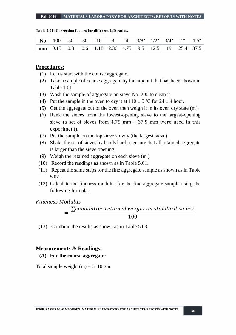
Table 5.01: Correction factors for different L/D ratios.
No 100 50 30 16 8 4 3/8'' 1/2'' 3/4'' 1'' 1.5''
mm 0.15 0.3 0.6 1.18 2.36 4.75 9.5 12.5 19 25.4 37.5
Procedures:
(1) Let us start with the course aggregate.
(2) Take a sample of coarse aggregate by the amount that has been shown in
Table 1.01.
(3) Wash the sample of aggregate on sieve No. 200 to clean it.
(4) Put the sample in the oven to dry it at 110 ± 5 ºC for 24 ± 4 hour.
(5) Get the aggregate out of the oven then weigh it in its oven dry state (m).
(6) Rank the sieves from the lowest-opening sieve to the largest-opening
sieve (a set of sieves from 4.75 mm – 37.5 mm were used in this
experiment).
(7) Put the sample on the top sieve slowly (the largest sieve).
(8) Shake the set of sieves by hands hard to ensure that all retained aggregate
is larger than the sieve opening.
(9) Weigh the retained aggregate on each sieve (mi).
(10) Record the readings as shown as in Table 5.01.
(11) Repeat the same steps for the fine aggregate sample as shown as in Table
5.02.
(12) Calculate the fineness modulus for the fine aggregate sample using the
following formula:
𝐹𝑖𝑛𝑒𝑛𝑒𝑠𝑠 𝑀𝑜𝑑𝑢𝑙𝑢𝑠
= ∑𝑐𝑢𝑚𝑢𝑙𝑎𝑡𝑖𝑣𝑒 𝑟𝑒𝑡𝑎𝑖𝑛𝑒𝑑 𝑤𝑒𝑖𝑔ℎ𝑡 𝑜𝑛 𝑠𝑡𝑎𝑛𝑑𝑎𝑟𝑑 𝑠𝑖𝑒𝑣𝑒𝑠
100
(13) Combine the results as shown as in Table 5.03.
Measurements & Readings:
(A) For the coarse aggregate:
Total sample weight (m) = 3110 gm.

Fall 2016 MATERIALS LABORATORY FOR ARCHITECTS: REPORTS WITH NOTES
ENGR. YASSER M. ALMADHOUN | MATERIALS LABORATORY FOR ARCHITECTS: REPORTS WITH NOTES 29
Table 5.02: Weights of the retained coarse aggregate on each sieve.
Sieve Size (mm) Sieve No. (#) Cumulative Retained
(gm)
75 3 0
50 2 0
37.5 1 ½ 0
25 1 0
19 ¾ 0
12.5 ½ 1125
9.5 3/8 1730
4.75 4 3110
(B) For the fine aggregate:
Total weight of coarse aggregate (m) = 834.7 gm.
Table 5.03: Weights of the retained fine aggregate on each sieve.
Sieve Size (mm) Sieve No. (#) Cumulative Retained
(gm)
1.18 16 737.7
0.6 30 754.5
0.425 40 764.7
0.3 50 768.3
0.15 100 784.9
0.075 200 816.2
Pan − 834.7
Calculations:
𝐶𝑢𝑚𝑢𝑙𝑎𝑡𝑖𝑣𝑒 𝑅𝑒𝑡𝑎𝑖𝑛𝑑 (%) =𝑊(𝑠𝑖𝑒𝑣𝑒 𝑟𝑒𝑡𝑎𝑖𝑛𝑖𝑛𝑔𝑠)
𝑊(𝑡𝑜𝑡𝑎𝑙)×100
𝐶𝑢𝑚𝑢𝑙𝑎𝑡𝑖𝑣𝑒 𝑃𝑎𝑠𝑠𝑖𝑛𝑔 (%) = 100 − 𝐶𝑢𝑚𝑢𝑙𝑎𝑡𝑖𝑣𝑒 𝑅𝑒𝑡𝑎𝑖𝑛𝑑
(A) For the coarse aggregate:
Total weight of coarse aggregate = 3110 gm.
For example: for sieve size 12.5 mm:
𝐶𝑢𝑚𝑢𝑙𝑎𝑡𝑖𝑣𝑒 𝑅𝑒𝑡𝑎𝑖𝑛𝑑 (%) =1125
3110×100 = 36.17 %

Fall 2016 MATERIALS LABORATORY FOR ARCHITECTS: REPORTS WITH NOTES
ENGR. YASSER M. ALMADHOUN | MATERIALS LABORATORY FOR ARCHITECTS: REPORTS WITH NOTES 30
𝐶𝑢𝑚𝑢𝑙𝑎𝑡𝑖𝑣𝑒 𝑃𝑎𝑠𝑠𝑖𝑛𝑔 (%) = 100 − 36.17 = 63.83 %
Table 5.04: Sieves procedural calculations for the coarse aggregate.
Sieve Size
(mm) Sieve No. (#)
Cumulative
Retained
(gm)
Cumulative
Retained
(%)
Cumulative
Sample
Passing
(%)
75 3 − − −
50 2 − − −
37.5 1 ½ 0 0.00 100.00
25 1 0 0.00 100.00
19 ¾ 0 0.00 100.00
12.5 ½ 1125 36.17 63.83
9.5 3/8 1730 55.63 44.37
4.75 4 3110 100.00 0.00
(B) For the fine aggregate:
Total weight of fine aggregate = 835.9 gm.
For example: sieve size 0.3 mm:
𝐶𝑢𝑚𝑢𝑙𝑎𝑡𝑖𝑣𝑒 𝑅𝑒𝑡𝑎𝑖𝑛𝑑 (%) =768.3
834.7×100 = 92.05 %
𝐶𝑢𝑚𝑢𝑙𝑎𝑡𝑖𝑣𝑒 𝑃𝑎𝑠𝑠𝑖𝑛𝑔 (%) = 100 − 92.05 = 7.95 %
Table 5.05: Sieves procedural calculations for the fine aggregate.
Sieve Size
(mm) Sieve No. (#)
Cumulative
Retained
(gm)
Cumulative
Retained
(%)
Cumulative
Sample
Passing
(%)
2 10 737.7 88.38 11.62
1.18 16 754.5 90.39 9.61
0.6 30 761.4 91.22 8.78
0.425 40 764.7 91.61 8.39
0.3 50 768.3 92.05 7.95
0.15 100 784.9 94.03 5.97
0.075 200 816.2 97.78 2.22
Pan – 834.7 100.00 0.00

Fall 2016 MATERIALS LABORATORY FOR ARCHITECTS: REPORTS WITH NOTES
ENGR. YASSER M. ALMADHOUN | MATERIALS LABORATORY FOR ARCHITECTS: REPORTS WITH NOTES 31
(C) For the mix of aggregate:
Total weight of mix of aggregate = 3950.9 gm.
Table 5.06: Sieves procedural calculations for the mix of aggregate.
Sieve Size
(mm) Sieve No. (#)
Cumulative
Retained
(gm)
Cumulative
Retained
(%)
Sample
Passing
(%)
75 3 0 0.00 100.00
50 2 0 0.00 100.00
37.5 1 ½ 0 0.00 100.00
25 1 0 0.00 100.00
19 ¾ 0 0.00 100.00
12.5 ½ 1125 36.12 63.88
9.5 3/8 1730 55.54 44.46
4.75 4 3110 99.84 0.16
2 10 737.7 88.25 11.75
1.18 16 754.5 90.26 9.74
0.6 30 761.4 91.09 8.91
0.425 40 764.7 91.48 8.52
0.3 50 768.3 91.91 8.09
0.15 100 784.9 93.90 6.10
0.075 200 816.2 97.64 2.36
𝐹𝑖𝑛𝑒𝑛𝑒𝑠𝑠 𝑀𝑜𝑑𝑢𝑙𝑢𝑠
=∑𝑐𝑢𝑚𝑢𝑙𝑎𝑡𝑖𝑣𝑒 𝑟𝑒𝑡𝑎𝑖𝑛𝑒𝑑 𝑤𝑒𝑖𝑔ℎ𝑡𝑠 𝑜𝑛 𝑠𝑡𝑎𝑛𝑑𝑎𝑟𝑑 𝑠𝑖𝑒𝑣𝑒𝑠
100
𝐹𝑖𝑛𝑒𝑛𝑒𝑠𝑠 𝑀𝑜𝑑𝑢𝑙𝑢𝑠
= ∑𝑐𝑢𝑚𝑢𝑙𝑎𝑡𝑖𝑣𝑒 𝑟𝑒𝑡𝑎𝑖𝑛𝑒𝑑 𝑜𝑛(0.15, 0.30, 0.60, 1.18, 2.36,4.75)
100
𝐹𝑖𝑛𝑒𝑛𝑒𝑠𝑠 𝑀𝑜𝑑𝑢𝑙𝑢𝑠 = 99.84 + 88.25 + 90.26 + 91.09 + 91.48 + 91.91
100= 5.5525 (𝑣𝑒𝑟𝑦 𝑐𝑜𝑎𝑟𝑠𝑒)
Charts & Analysis:
After the analysis of the data. Charts had been drawn in logarithm scales by
means of any helping program. The Microsoft Office Excel was used in this
report (see the charts below).

Fall 2016 MATERIALS LABORATORY FOR ARCHITECTS: REPORTS WITH NOTES
ENGR. YASSER M. ALMADHOUN | MATERIALS LABORATORY FOR ARCHITECTS: REPORTS WITH NOTES 32
Chart 5.01: Sieve analysis for the coarse aggregate.
Chart 5.02: Sieve analysis for the fine aggregate.

Fall 2016 MATERIALS LABORATORY FOR ARCHITECTS: REPORTS WITH NOTES
ENGR. YASSER M. ALMADHOUN | MATERIALS LABORATORY FOR ARCHITECTS: REPORTS WITH NOTES 33
Chart 5.03: Sieve analysis for the mix of aggregate.
Results & Discussion:
After all calculations which had been made, we have found that:
For coarse aggregate:
The relationship between the sieves sizes and the percent
passing for the coarse aggregate is represented in the Chart
5.01.
For fine aggregate:
The relationship between the sieves sizes and the percent
passing for the fine aggregate is represented in the Chart
5.02.
Fineness Modulus = 5.593
Comments:
The fineness modulus of the fine aggregate sample is too big which means
that this aggregate is not suitable for mixing. Therefore, the aggregate is
very coarse.
The aggregate samples are not suitable options for a dense concrete.

Fall 2016 MATERIALS LABORATORY FOR ARCHITECTS: REPORTS WITH NOTES
ENGR. YASSER M. ALMADHOUN | MATERIALS LABORATORY FOR ARCHITECTS: REPORTS WITH NOTES 34
Experiment Report (06)
Unit Weight of Fresh Concrete
(ASTM C 138 ─ 81)
Introduction:
The Unit Weight (U.W) can be defined as the weight of a unit volume
of concrete mix.
Unit Weight is a necessary measurement for fresh concrete since it can help:
— for concrete mix design and how to design shattering.
— it can also help in the determination of the distances between joints
or columns.
Objectives:
Determination of the Unit Weight of a sample of fresh concrete.
Apparatus:
(1) Tamper rod.
(2) Scoop or shovel.
(3) A sensitive balance.
(4) Mallet.
(5) Measure: a cylindrical container with a capacity as in Table 6.01:

Fall 2016 MATERIALS LABORATORY FOR ARCHITECTS: REPORTS WITH NOTES
ENGR. YASSER M. ALMADHOUN | MATERIALS LABORATORY FOR ARCHITECTS: REPORTS WITH NOTES 35
Table 6.01: Capacity of the measure used.
M.A.S (mm) Capacity of measure (liter)
25 6
25 6
38 11
50 14
Procedures:
(1) Firstly, secure a sample.
(2) Then fill one-third of the measure by fresh concrete (layer 1), and tamp it
25 times.
(3) After that fill two-third of the measure by fresh concrete (layer 2), and tamp
it 25 times.
(4) Fill the measure completely and level its surface using the mallet and then
tamp it 25 times.
(5) After tamping: if any spaces encountered, tap the sides of the measure 10
times by the mallet.
(6) Scrape the excess concrete on the exterior surface of the measure.
(7) Weigh the measure filled with the fresh concrete (WA), and weigh the
measure only while it is empty (WB).
Measurements & Readings:
𝑈𝑛𝑖𝑡 𝑊𝑒𝑖𝑔ℎ𝑡 = 𝑊𝐴 − 𝑊𝐵
𝑉
Where:
WA: weight of the measure filled with fresh concrete.
WB: weight of the measure only.
V: volume of the measure.
Wmold+concrete = 24520 gm
Wmold = 6470 gm
Volume = 10 liter

Fall 2016 MATERIALS LABORATORY FOR ARCHITECTS: REPORTS WITH NOTES
ENGR. YASSER M. ALMADHOUN | MATERIALS LABORATORY FOR ARCHITECTS: REPORTS WITH NOTES 36
Calculations:
𝑈𝑛𝑖𝑡 𝑊𝑒𝑖𝑔ℎ𝑡 = ( 24520 – 6470 )×10−3
10×10−3= 1805 𝑘𝑔/𝑚3
Results & Discussion:
After all calculations which had been made, we have found that:
The unit weight equals to 1805 gm/cm3.
Comments:
The presence of entrained air bubbles affects the unit weight, since air
contributes to the measure volume but not to measure weight.

Fall 2016 MATERIALS LABORATORY FOR ARCHITECTS: REPORTS WITH NOTES
ENGR. YASSER M. ALMADHOUN | MATERIALS LABORATORY FOR ARCHITECTS: REPORTS WITH NOTES 37
Experiment Report (07)
The Slump of Hydraulic Cement Concrete
(ASTM C 143 ─ 89a)
Introduction:
This experiment is used in determining the slump of freshly mixed
concrete, which is an approximate measure of workability. The test may be done
in laboratory and in field.
Types of slump:
There are three types of slump that may occur in a slump test namely, true slump,
shear slump and collapse slump.
(i) True Slump refers to the general drop of the concrete mass evenly all
around without disintegration.
(ii) Shear Slump indicates that the concrete lacks cohesion. It may undergo
segregation and bleeding and thus it is undesirable for the durability.
(iii) Collapse Slump indicates that concrete mix is too wet. Therefore, the
mix is regarded as harsh and lean.
Objectives:
Determination of the slump value of a sample of freshly mixed concrete.

Fall 2016 MATERIALS LABORATORY FOR ARCHITECTS: REPORTS WITH NOTES
ENGR. YASSER M. ALMADHOUN | MATERIALS LABORATORY FOR ARCHITECTS: REPORTS WITH NOTES 38
TABLE 7.01: Types of slump.
Consistency grade Slump (mm) Recommended method
of compaction
Stiff, Kl 0 – 60 Mechanical compaction
like vibration
Plastic, K2 60 – 130
Mechanical or hand
compaction (rodding or
tampering)
Flowing, K3 130 – 200 Hand compaction or no
compaction
Self-compacting, K4 ≥ 200 No compaction
TABLE 7.02: recommended slump for various types of construction.
Type of Construction
Slump
(mm) (inches)
Min Max Min Max
Reinforced foundation
walls and footings 25 75 1 3
Plain footings, caissons and
substructure walls 25 75 1 3
Beams and reinforced walls 25 100 1 4
Building columns 25 100 1 4
Pavements and slabs 25 75 1 3
Mass concrete 25 50 1 2
Apparatus:
(1) Weight and weighing devices.
(2) Tools and containers for mixing, or concrete mixer.
(3) Tamper (16 mm in diameter and 600 mm length).
(4) Ruler.
(5) Slump cone which has the shape of a frustum of a cone with the following
dimensions:
Base diameter 20 cm.

Fall 2016 MATERIALS LABORATORY FOR ARCHITECTS: REPORTS WITH NOTES
ENGR. YASSER M. ALMADHOUN | MATERIALS LABORATORY FOR ARCHITECTS: REPORTS WITH NOTES 39
Top diameter 10 cm.
Height 30 cm.
Materials thickness at least 1.6 mm.
Procedures:
(1) Firstly, put the sample which has been represented in the previous tests.
(2) Take the cone and put it on a flat surface (a plate) that does not absorb
water.
(3) During putting the specimen, keep to hold the cone clearly.
(4) Then, fill the mold (or the cone) on three layers.
(5) Each layer has to be stroked uniformly 25 times by 16 mm rod.
(6) Level the top surface by a flat trowel and clean the plate.
(7) As soon as lift the mold up (or the cone) vertically.
(8) Finally, measure the slump value which is the difference between the top
of the cone and the center of the top surface of the concrete pile.
Measurements & Readings:
Slump value = Cone height (30 cm) – height of the sample after subsidence.
Slump value = 12 cm.
Fall 2016 MATERIALS LABORATORY FOR ARCHITECTS: REPORTS WITH NOTES
ENGR. YASSER M. ALMADHOUN | MATERIALS LABORATORY FOR ARCHITECTS: REPORTS WITH NOTES 40
Comments:
During tamping, we kept the rod just penetrates into the underlying layer.
The previous steps should be finished in less than 2.5 minutes.
This slump value indicates that the mix is not workable adequately.
If we make the slump test after a period of time, we will note that this
value will decrease, because of the time-temperature agent.

Fall 2016 MATERIALS LABORATORY FOR ARCHITECTS: REPORTS WITH NOTES
ENGR. YASSER M. ALMADHOUN | MATERIALS LABORATORY FOR ARCHITECTS: REPORTS WITH NOTES 41
Experiment Report (08)
Production of Concrete Specimens
(ASTM C 31 ─ 84)
Introduction:
This experiment aims at producing concrete specimens for tests. Those
tests are to be applied to a hardened concrete specimen which has to be produced
according to a procedure adopted by various codes.
Objectives:
Production of specimens by the specified procedures for the comparison with the
specifications in other tests in order to gain more confidence of those tests
results.
Apparatus:
(1) Tamping rod.
(2) Scoop.
(3) Molds: there are two kinds of molds:
B.S molds:
(10×10×10) cm {2 layers with 25 strokes on each layer}.
(15×15×15) cm {3 layers with 35 strokes on each layer}.
ASTM molds:
Cylinder with 15 cm diameter, 30 cm length.
{3 layers with 25 strokes on each layer}.
Procedure:
(1) B.S molds were used for producing the specimens.
(2) Place specimens in moist temperature room with temperature of 23 ± 1.7
°C until the moment of a test.
(3) Demold the specimens after 24 hours of curing.
Comments:
At the next experiments, tests will be done on the specimens that had been
produced as per the adopted specifications, and they will be used for

Fall 2016 MATERIALS LABORATORY FOR ARCHITECTS: REPORTS WITH NOTES
ENGR. YASSER M. ALMADHOUN | MATERIALS LABORATORY FOR ARCHITECTS: REPORTS WITH NOTES 42
obtaining some important results in virtue of doing some tests and
calculations.

Fall 2016 MATERIALS LABORATORY FOR ARCHITECTS: REPORTS WITH NOTES
ENGR. YASSER M. ALMADHOUN | MATERIALS LABORATORY FOR ARCHITECTS: REPORTS WITH NOTES 43
Experiment Report (09)
Density of Hardened Concrete
(ASTM C 642 ─ 13)
Introduction:
The determination of the density of hardened concrete is very important,
which is useful to know the own weight of the structure elements. Furthermore,
the increasing of concrete own weight indicates increasing of concrete own
strength.
Objectives:
Determination of the density of hardened concrete.
Apparatus:
(1) A sensitive balance.
(2) Caliper.
Procedures:
(1) Get the sample out of the water tank.
(2) Measure its dimensions using the caliper.
(3) Weigh the sample by means of the sensitive balance to get its mass (m).
(4) Calculate the density of the concrete specimen using the following
equation:
𝜌 =𝑚
𝑉
NB: Calculations of the density of hardened concrete are contained in the next
experiment report. It will be calculated for each concrete specimen in sequence.

Fall 2016 MATERIALS LABORATORY FOR ARCHITECTS: REPORTS WITH NOTES
ENGR. YASSER M. ALMADHOUN | MATERIALS LABORATORY FOR ARCHITECTS: REPORTS WITH NOTES 44
Experiment Report (10)
The Compressive Strength of Cubic Concrete Specimens
(BS 1881: Part 116: 1983)
Introduction:
Compressive strength test results are primarily used to determine that the
concrete mixture as delivered meets the requirements of the specified strength
𝑓𝑐′ in the job specification. Strength test results from cast cylinders may be used
for quality control, acceptance of concrete, estimating the concrete strength in a
structure for the purpose of scheduling construction operations such as form
removal, or for evaluating the adequacy of curing and protection afforded to the
structure. Cylinders tested for acceptance and quality control are made and cured
in accordance with procedures described for standard-cured specimens in ASTM
C31 Standard Practice for Making and Curing Concrete Test Specimens in the
Field. For estimating the in-place concrete strength, ASTM C 31 provides
procedures for Field-Cured Specimens.
Objectives:
Determination of the compressive strength of cubic concrete specimens.
Definitions:
Compressive Strength: capacity of material to withstand compressive
normal forces.
𝑓𝑐′ =𝑃
𝐴
Where:
P = maximum load.
A = the cross sectional area of the specimen.
Density of Concrete: mas of hardened concrete in a unit volume.
𝜌 =𝑚
𝑉

Fall 2016 MATERIALS LABORATORY FOR ARCHITECTS: REPORTS WITH NOTES
ENGR. YASSER M. ALMADHOUN | MATERIALS LABORATORY FOR ARCHITECTS: REPORTS WITH NOTES 45
Where:
ρ: density of concrete specimen.
m: mass of the sample.
V: volume of the sample.
Apparatus:
(1) Testing machine.
(2) A balance of an accuracy of 0.1% of the weight of the sample.
Procedures:
i. Preparation of concrete:
(1) Mix proportions as follows:
Cement Fine aggregate Coarse aggregate Water
1.0 2.0 4.0 0.5

Fall 2016 MATERIALS LABORATORY FOR ARCHITECTS: REPORTS WITH NOTES
ENGR. YASSER M. ALMADHOUN | MATERIALS LABORATORY FOR ARCHITECTS: REPORTS WITH NOTES 46
(2) Add the coarse aggregate with some of the mixing water and then run the
mixer.
(3) Add the fine aggregate, cement and the rest of the water while the mixer
is running.
(4) Left the mixer running for 3 minutes after adding all materials, then rest
the mixer for 3 minutes and then mix for 2 minutes.
NB: cover the mixer during the rest period.
(5) Obtain the mix concrete, and put it into a clean pan then remix it using a
shovel to eliminate segregation.
ii. Preparation of cubes:
For the cube of 15 cm: Figure 10.01
(1) Fill the cube on three layers.
(2) Fill the first layer of the cube (one third of the cube height) and tamp it 35
strokes distributed uniformly on the whole surface of the cube by using a
tamper (2.5 cm × 2.5 cm).
(3) Fill the second layer and the last layer and tamp each one as likely as the
first layer.
(4) Level the surface of the cube using the trowel.
(5) Left the cube for 24 hours in a wet place (humid air).
(6) Put the cubes in the curing bowl until you do the test.
(7) Bring the cubes before 15 minutes from making the test and dry their
surfaces.
For the cube of 10 cm: Figure 10.02
(1) Fill the cube on two layers.
(2) Fill the first layer of the cube (half of the cube height) and tamp it 25
strokes distributed uniformly on the whole surface of the cube using a
tamper (2.5 cm × 2.5 cm).
(3) Fill the second layer and tamp it as likely as the first layer.
(4) Level the surface of the cube using the trowel.
(5) Left the cube for 24 hours in a wet place (humid air).
(6) Put the cubes in the curing bowl until you do the test.
(7) Bring the cubes before 15 minutes from making the test and dry their
surfaces.

Fall 2016 MATERIALS LABORATORY FOR ARCHITECTS: REPORTS WITH NOTES
ENGR. YASSER M. ALMADHOUN | MATERIALS LABORATORY FOR ARCHITECTS: REPORTS WITH NOTES 47
iii. Breaking of the cubes: Figure 10.01 & Figure 10.02
(1) Measure the average length (L) of the sample.
(2) Calculate the volume of the cubes in m3 as follows:
𝑉 = 𝐿×𝑤×ℎ
(3) Weigh the cubes (W10-cm-cube, W15-cm-cube).
(4) Put the cubes in the compressive testing machine, and take into
consideration breaking on the leveled surface by a tamper is prevented.
(5) Record the maximum load when the cube breaks (Pcom).
(6) Compute the compressive strength of the concrete using the following
equation:
𝑓𝑐′ =𝑃
𝐴
(7) Compare the results with the ASTM specifications which are shown in
the following table:
Table 10.01: Minimum percent compressive strength acquired after n days.
Age of Specimen (n days) Minimum 𝒇𝒄′ of 𝒇𝒄′ (28 days)
3 (40 – 50) %
7 (65 – 70) %
14 (80 – 90) % ≃ 85 %

Fall 2016 MATERIALS LABORATORY FOR ARCHITECTS: REPORTS WITH NOTES
ENGR. YASSER M. ALMADHOUN | MATERIALS LABORATORY FOR ARCHITECTS: REPORTS WITH NOTES 48
Measurements & Readings:
The results of testing each three cubic specimens should be arranged in a table
as shown below:
Table 10.02: Sample record table.
Cube No. Load (KN) Compressive Strength
(MPa)
However, here we used only one cubic specimen from each type for testing, and
the results were as below:
For the cube of 10 cm For the cube of 15 cm
NB: The rate of loading = 6 KN/second.

Fall 2016 MATERIALS LABORATORY FOR ARCHITECTS: REPORTS WITH NOTES
ENGR. YASSER M. ALMADHOUN | MATERIALS LABORATORY FOR ARCHITECTS: REPORTS WITH NOTES 49
Calculations:
a. For the cube of 15 cm:
𝐴 = 15.2×15 = 288 𝑐𝑚2 = 228×10−4 𝑚2
𝑉 = 15.2×15×15 = 3420 𝑐𝑚3 = 3420×10−6 𝑚3
𝜌 =7.990
3420×10−6= 2336.2573 𝑘𝑔/𝑚3
𝑓𝑐′ =552.110 ×10³
228×10−4= 24.2154×10⁶ 𝑁/𝑚2 = 24.2154 𝑀𝑃𝑎
𝑓𝑐′ = (552.110 ×10³)/9.81
228= 246.8435 𝑘𝑔/𝑐𝑚2
b. For the cube of 10 cm:
𝐴 = 10.2×10 = 102 𝑐𝑚2 = 102×10−4 𝑚2
𝑉 = 10.2×10×10 = 1020 𝑐𝑚3 = 1020×10−6 𝑚3
𝜌 =2.405
1020×10−6= 2357.8431 𝑘𝑔/𝑚3
𝑓𝑐′ =169.008×10³
102×10−4= 16.5694×10⁶ 𝑁/𝑚2 = 16.5694 𝑀𝑃𝑎
𝑓𝑐′ = 16.5694×0.975 = 16.1552 𝑀𝑃𝑎
𝑓𝑐′ = (169.008 ×10³)/9.81
102= 168.9033 𝑘𝑔/𝑐𝑚2
𝑓𝑐′ = 168.9033×0.975 = 164.6807 𝑘𝑔/𝑐𝑚2
c. For the conversion from 10cm-cube to 15cm-cube:
𝑓𝑐′(15𝑐𝑚) = 𝑓𝑐′(10𝑐𝑚)×0.975

Fall 2016 MATERIALS LABORATORY FOR ARCHITECTS: REPORTS WITH NOTES
ENGR. YASSER M. ALMADHOUN | MATERIALS LABORATORY FOR ARCHITECTS: REPORTS WITH NOTES 50
Results & Discussion:
After all calculations which had been made, we have found that:
a. For the cube of 15 cm:
𝜌 = 2336.2573 𝑘𝑔/𝑚3
𝑓𝑐′ = 24.2154 𝑀𝑃𝑎
𝑓𝑐′ = 246.8435 𝑘𝑔/𝑐𝑚2
b. For the cube of 10 cm:
𝜌 = 2357.8431 𝑘𝑔/𝑚3
𝑓𝑐′ = 16.1552 𝑀𝑃𝑎
𝑓𝑐′ = 164.6807 𝑘𝑔/𝑐𝑚2
𝑓𝑐′𝑎𝑣𝑒𝑟𝑎𝑔𝑒
=24.2154 + 16.1552
2= 20.1853 𝑀𝑃𝑎
c. For the cylinder:
𝑓𝑐′ = 16.1552 𝑀𝑃𝑎
𝑓𝑐′ = 164.6807 𝑘𝑔/𝑐𝑚2
Comments:
The cubic concrete specimen should be subjected to loads on flat faces
whereas the external leveled surface by tamper should be excluded.
The fc' of the cube of 10 cm is less than fc' of the cube of 15 cm, which
indicates that there is a problem in the preparation procedures of the cube
of 10 cm.
This test follows the B.S specification.
The cylindrical specimen was not used for the compressive strength test.

Fall 2016 MATERIALS LABORATORY FOR ARCHITECTS: REPORTS WITH NOTES
ENGR. YASSER M. ALMADHOUN | MATERIALS LABORATORY FOR ARCHITECTS: REPORTS WITH NOTES 51
Experiment Report (11)
Destructive Test (Core Test)
(C 42 / C 42M ─ 04)
Introduction:
This test method covers obtaining, preparing, and testing cores drilled
from concrete for length, compressive strength, or splitting tensile strength
determinations. This test method is not applicable to cores from shotcrete
applications.
When compressive strength tests of laboratory-cured cylinders fail to meet the
specified acceptance criteria, core tests are commonly used to verify the strength
and to obtain acceptance of the in-place (in-situ) concrete. Although, the process
of core testing may seem straightforward, there are many details that contractors
have to consider to achieve accurate results.
Conditions for concrete core sample:
(1) Use the correction factor for a cylinder sample with 1 ≤ 𝐿/𝐷 ≤ 2.
(2) Take the samples from the position of zero shear (mid of span).
(3) Age of the samples must be older than 14 days.
(4) Test is to be made after 28 days.
(5) Reduce number of reinforcing steel bars as much as possible.
(6) The existed number of reinforcing steel bars in a core sample needs a
corrections factor.
Objectives:
Determination of compressive strength of cube concrete specimens.
Apparatus:
(1) Drilled cores.
(2) Testing machine.

Fall 2016 MATERIALS LABORATORY FOR ARCHITECTS: REPORTS WITH NOTES
ENGR. YASSER M. ALMADHOUN | MATERIALS LABORATORY FOR ARCHITECTS: REPORTS WITH NOTES 52
Procedures:
Take core sample as drawn in the following steps:
(1) Keep the core machine vertically on the surface where the sample is to be
taken.
(2) Determine the diameter of the sample for the machine and you should
work to create a sample that has 1 ≤ 𝐿/𝐷 ≤ 2.
(3) Make a cap for the sample.
a. Freshly molded cylinders:
Only neat Portland cement paste (2 – 4 hours after molding)
b. Hardened concrete core:
Highly strength gypsum plaster or neat cement paste:
Capping plates may be removed within 45 minutes with
gypsum plaster or 12 hours with neat cement.
Sulfur mortar:
Must be heated to a temperature (130 – 134 °C).
NB: The thickness of the cap must be no more than 3 mm for
durability, and it must bear the loads that the concrete specimen
resists.
(4) Put the sample in the testing machine and record the magnitude of load.
(5) Determine the compressive strength as follows:
𝑓𝑐′(𝑐𝑦𝑙𝑖𝑛𝑑𝑒𝑟) = 𝑃
𝐴×𝐶𝑜𝑟𝑟𝑒𝑐𝑡𝑖𝑜𝑛 𝐹𝑎𝑐𝑡𝑜𝑟 𝑓𝑜𝑟 (𝐿/𝐷)
𝑓𝑐′(𝑐𝑢𝑏𝑒) = 10
8×𝑓𝑐′(𝑐𝑦𝑙𝑖𝑛𝑑𝑒𝑟)

Fall 2016 MATERIALS LABORATORY FOR ARCHITECTS: REPORTS WITH NOTES
ENGR. YASSER M. ALMADHOUN | MATERIALS LABORATORY FOR ARCHITECTS: REPORTS WITH NOTES 53
If the ratio of the specimen length to its diameter is less than 1.80, you have to
correct the result obtained by multiplying the appropriate correction factor taken
from the following table:
Table 11.01: Correction factors for different L/D ratios.
L/D 1.75 1.50 1.25 1.00
Factor 0.98 0.96 0.93 0.87
NB: Factors are applicable for normal concrete strengths from 14.4 to 42 MPa.
Comments:
For a tested cylinder fc':
fc' (average) > 0.85 fc' (a condition that is required).
fc' for each sample > 0.75 fc’ (a condition that is required).
If the core test failed, there are other solutions, such as:
Reloading.
Redesign.
Loading test.

Fall 2016 MATERIALS LABORATORY FOR ARCHITECTS: REPORTS WITH NOTES
ENGR. YASSER M. ALMADHOUN | MATERIALS LABORATORY FOR ARCHITECTS: REPORTS WITH NOTES 54
Experiment Report (12)
Steel Tensile Test
(ASTM A 370 ─ 03a)
Introduction:
The most common material on construction sector besides concrete is
steel. Concrete, though it has a high compressive strength, its tensile strength is
usually much lower and mounts up to 8 – 12 % of its compressive strength. Steel,
therefore, is used in concrete structural elements to bare tensile loads and
bending moments.
The methodology of this experiment is to incrementally load a steel bar until
failure, while recording the value of the load and the change in length of the steel
bar at each stage.
Objectives:
Determination of the yield strength, ultimate strength and elongation of steel,
and to plot the stress-strain diagram.
Definitions:
Ductility:
The ability of a material to retain its initial length after the loads had been
removed within the elastic range of that material.
Yield Point:
It is the Point at which an increase in strain occurs without an increase in the
stress.
𝑓𝑦 =𝑃𝑦
𝐴
Where: A: cross sectional area of steel bar.

Fall 2016 MATERIALS LABORATORY FOR ARCHITECTS: REPORTS WITH NOTES
ENGR. YASSER M. ALMADHOUN | MATERIALS LABORATORY FOR ARCHITECTS: REPORTS WITH NOTES 55
Ultimate Point:
It is the point at which an increase in stress occurs without an increase in the
strain.
𝑓𝑢 = 𝑃𝑢
𝐴
Elongation:
𝐸𝑙 (%) =𝐿𝑓 − 𝐿𝑖
𝐿𝑖×100
Where:
Lf: final length.
Li: initial length.
Reduction of Area:
𝑅𝐴 =∆𝐴
𝐴𝑖
×100
Modulus of Elasticity:
𝐸 =𝜎
𝜀
Reinforcing steel bars are usually manufactured in three different forms:
(1) Plain bars.
(2) Deformed bars.
(3) Plain and deformed wires (used in pre-stressed applications).
NB: The deformation in deformed steel bars is intended to increase the bonding
strength between steel and concrete and to prevent slippage of the steel
reinforcement bars.

Fall 2016 MATERIALS LABORATORY FOR ARCHITECTS: REPORTS WITH NOTES
ENGR. YASSER M. ALMADHOUN | MATERIALS LABORATORY FOR ARCHITECTS: REPORTS WITH NOTES 56
Steel reinforcement bars are produced mainly with four different yield strengths,
shown in the table below. The grade of steel indicates its yield strength in
kilopond per square inch (ksi).
Table 12.01: Reinforcement steel yield strength.
Type σyield (psi) σyield (MPa) Grade
Type1 40,000 300 40
Type 2 50,000 350 50
Type 3 60,000 400 60
Type 4 75,000 500 75
Typical Stress-Strain Curve:

Fall 2016 MATERIALS LABORATORY FOR ARCHITECTS: REPORTS WITH NOTES
ENGR. YASSER M. ALMADHOUN | MATERIALS LABORATORY FOR ARCHITECTS: REPORTS WITH NOTES 57
Apparatus:
(1) Universal testing machine.
(2) Dial gauge / Extensometer.
(3) Steel bar for testing.
Procedures:
(1) Get a bar of steel and measure its length which should not be less than 14
times its diameter (𝐿 ≥ 14 𝐷).
(2) Fix the ends of the bar to the grips and place the extensometer on the bar.
The distance between the extensometer ends is 20 cm (Li). Further, mark
a distance of 20 cm on the bar before starting.
(3) Apply the load with a rate.
(4) Record the load with its corresponding elongation until the specimen fails.
(5) Observe the elastic behavior, yield point, plastic behavior, necking and
failure.
NB: For the steel bar which is to be tested, the results should be as per the ASTM
specifications as given as under:
𝑌𝑖𝑒𝑙𝑑 𝑠𝑡𝑟𝑒𝑠𝑠, 𝑓𝑦 𝑓𝑦 = (400 − 520) 𝑀𝑃𝑎.
𝑈𝑙𝑡𝑖𝑚𝑎𝑡𝑒 𝑠𝑡𝑟𝑒𝑠𝑠, 𝑓𝑢 𝑓𝑢 > 500 𝑀𝑃𝑎.
𝐸𝑙𝑜𝑛𝑔𝑎𝑡𝑖𝑜𝑛, 𝐸𝑙. (%) 𝐸𝑙. < 12 %.
Measurements & Readings:
The results of the test were as follows:
𝑑 = 14 𝑚𝑚 (∅14)

Fall 2016 MATERIALS LABORATORY FOR ARCHITECTS: REPORTS WITH NOTES
ENGR. YASSER M. ALMADHOUN | MATERIALS LABORATORY FOR ARCHITECTS: REPORTS WITH NOTES 58
P𝑦 = 76 𝐾𝑁
P𝑢 = 111 𝐾𝑁
L𝑖 = 20 𝑐𝑚
L𝑓 = 22 𝑐𝑚
Calculations:
𝐴𝑖 = (𝜋
4) ×𝑑2 = (
𝜋
4) ×(14)2 = 153.938 𝑚𝑚2
𝑓𝑦 = 76×103
(𝜋4
) ×(14)2= 493.705 𝑀𝑃𝑎
𝑓𝑢 = 111×103
(𝜋4
) ×(14)2= 721.069 𝑀𝑃𝑎
𝐸𝑙 (%) = 22 − 20
20×100 = 10 %
Results & Discussion:
After all calculations which had been made, we have found that:
𝑓𝑦 = 493.705 MPa (ok; as per ASTM).
𝑓𝑢 = 721.069 MPa (ok; as per ASTM).
𝐸𝑙 (%) = 10 % (ok; as per ASTM).
Comments:
The result of 𝑓𝑦 falls within 400-500 MPa, so, the sample is good.
The result of 𝑓𝑢
is more than 500 MPa so, the sample is good.
The elongation of this sample = 10 %, satisfies the condition of ASTM.
So, the sample is very good.

Fall 2016 MATERIALS LABORATORY FOR ARCHITECTS: REPORTS WITH NOTES
ENGR. YASSER M. ALMADHOUN | MATERIALS LABORATORY FOR ARCHITECTS: REPORTS WITH NOTES 59
Experiment Report (13)
Steel Bend and Re-bend Test
(ASTM E 290 ─ 14)
Introduction:
Bend tests for ductility provide a simple way to evaluate the quality of
materials by their ability to resist cracking or other surface irregularities during
one continuous bend. No reversal of the bend force shall be employed when
conducting these tests.
Objectives:
Determination of the elasticity and ductility of a reinforcing steel bar.
Apparatus:
(1) Bending Device.
(2) Steel bar for testing.
Procedures:
(1) Put the steel sample on the machine, then start loading until you get an
angle about 90°.
(2) Put the steel sample in the other direction, then start loading until you get
an angle about 20°.
(3) Look at the steel sample to see if there any cracks occur.

Fall 2016 MATERIALS LABORATORY FOR ARCHITECTS: REPORTS WITH NOTES
ENGR. YASSER M. ALMADHOUN | MATERIALS LABORATORY FOR ARCHITECTS: REPORTS WITH NOTES 60
Measurements & Results:
The results of the test were as follows:
The test that had been made, indicates that the steel bar sample succeeded in the
test, and comply to the adopted specifications (Bend to 90 and Re-bend to 20).
Comments:
The sample of reinforcing steel bar passed this test, since there no cracks
took place.

Fall 2016 MATERIALS LABORATORY FOR ARCHITECTS: REPORTS WITH NOTES
ENGR. YASSER M. ALMADHOUN | MATERIALS LABORATORY FOR ARCHITECTS: REPORTS WITH NOTES 61
Experiment Report (14)
Tiles Tests
(PS-13: March 1997)
Introduction:
This test covers the methods of tiles testing which aim to know the
efficiency of tiles and their properties.
Tiles components: a tile consists of two layers:
(1) Wearing layer: which accounts a thickness of 0.5 cm.
(2) Concrete layer: which varies in thickness as the thickness of the tile
varies.
Tests for tiles:
(1) Vision test.
(2) Dimensions test.
(3) Absorption test.
(4) Flexural test.
(5) Abrasion test.
Definitions:
Absorption:
𝐴(%) =𝑊𝑆𝑆𝐷 − 𝑊𝑂𝐷
𝑊𝑂𝐷
×100
Flexural strength:
𝑓𝑐′ =3 𝑃𝐿
2𝑏𝑑2
Abrasion:
𝐴𝑏 = 𝐿𝑖 − 𝐿𝑓
Objectives:
This test covers the determination of the efficiency and the quality of tiles.

Fall 2016 MATERIALS LABORATORY FOR ARCHITECTS: REPORTS WITH NOTES
ENGR. YASSER M. ALMADHOUN | MATERIALS LABORATORY FOR ARCHITECTS: REPORTS WITH NOTES 62
Apparatus:
(1) Flexural test machine.
(2) Abrasion test machine.
(3) Perpendicularity apparatus.
(4) Fill apparatus.
(5) Corundum sand.
Procedures:
(a) Dimension Test:
(1) Side length: measure the dimensions of the sample. The difference in
a dimension should not exceed 0.50 mm
(2) Plainness: change in tropical surface (concavity or convexity). It
should be less than 0.50 mm.
(3) Straightness: change in tropical rib. It should be less than 0.20 % by
the side length.
(4) Perpendicularity: angles of the tiles should equal 90°, whereas δ in
perpendicularity should be less than 0.34 % from the side length.
(5) Wearing layer thickness: should be more than 4 mm .
(b) Absorption Test:
(1) Put the sample in water for 24 hours, then make it in the SSD state by
drying the outer surface of the sample tile, and then weigh the sample
(WSSD).
(2) Put the sample in the oven until you get the OD state, and then weigh
the sample (WOD).
(3) Calculate the absorption using the following formula:
𝐴 =𝑊𝑆𝑆𝐷 − 𝑊𝑂𝐷
𝑊𝑂𝐷×100
(4) It should be more than 9% as per ASTM specifications.
(c) Flexural Strength Test:
(1) Age of the samples should be more than 28 days.
(2) Put the sample in water for 18 hours, then make it in the SSD state.
(3) The length between the two supports of the machine, B = L–50 mm.
For example: if the tile has 250 ×250 mm dimensions, then B = L–50
mm = 250–50 = 200 mm.
(4) Start the manual loading, and record the load at which the tile sample
breaks.
(5) Calculate the flexural strength of the samples using the following
formula:
𝑓𝑐′ =3 𝑃𝐿
2𝑏𝑑2

Fall 2016 MATERIALS LABORATORY FOR ARCHITECTS: REPORTS WITH NOTES
ENGR. YASSER M. ALMADHOUN | MATERIALS LABORATORY FOR ARCHITECTS: REPORTS WITH NOTES 63
(d) Abrasion Test:
(1) Ab = (Li − Lf) < 3.0 mm (condition).
(2) Use sample with dimensions of 7 × 7 cm.
(3) Put the wearing layer on the machine and make it rotates 10 times with
22 rotations in each time.
(4) Use 20 gm of the corundum sand in each time.
(5) Change the direction of rotation (rotate the sample by 90°), and again
make the sample rotates 10 times with 22 rotations in each one.
Measurements & Readings:
The results of the test were as follows:
Dimensions of the used tile sample: 250 × 250 mm
Dimensions Test:
Plainness = 0.30 mm
Straightness = 0.10 mm
Perpendicularity = 0.15 mm
Wearing layer thickness = 8.0 mm
Flexural Strength Test:
P = 2640 N
L = 200 mm
d = 24 mm
b = 250 mm
Abrasion Test:
Dimensions of the sample: 7 × 7 cm
Initial length (Li) = 50 mm
Final length(Lf) = 47.90 mm
Marble stone

Fall 2016 MATERIALS LABORATORY FOR ARCHITECTS: REPORTS WITH NOTES
ENGR. YASSER M. ALMADHOUN | MATERIALS LABORATORY FOR ARCHITECTS: REPORTS WITH NOTES 64
Calculations:
Dimensions Test:
Plainness = 0.3 mm by convexity.
Straightness = (0.1
250) ×100 = 0.04 %
Perpendicularity = (0.15
250) ×100 = 0.06 %
Wearing layer thickness = 8 mm
Flexural Strength Test:
𝑓𝑐′ =3 𝑃𝐿
2𝑏𝑑2=
3×2640× 0.20
2×0.25×0.0242= 5.50 𝑀𝑃𝑎
Abrasion Test:
𝐴𝑏 = 𝐿𝑖 − 𝐿𝑓 = 50.0 − 47.9 = 2.10 𝑚𝑚
Results & Discussion:
After all calculations which had been made, we have found that:
Dimension Test:
Plainness = 0.3 mm (convexity).
Straightness = 0.04 %
Perpendicularity = 0.06 %
Wearing layer thickness 8.0 mm
Flexural Strength Test:
fc’ = 5.50 MPa
Abrasion Test:
Ab = 2.10 mm
Comments:
According to (P.S) Standards:
Dimension Test:
Plainness = 0.3 mm < 0.5 mm (acceptable).
Straightness = 0.04 % < 0.2 % (acceptable).
Perpendicularity = 0.06 % < 0.34 % (acceptable).
Wearing layer thickness = 8.0 mm > 4.0 mm (acceptable).

Fall 2016 MATERIALS LABORATORY FOR ARCHITECTS: REPORTS WITH NOTES
ENGR. YASSER M. ALMADHOUN | MATERIALS LABORATORY FOR ARCHITECTS: REPORTS WITH NOTES 65
Abrasion Test:
Abrasion = 2.10 mm < 3.0 mm (acceptable). Hence, marble stone
is poor in abrasion resistance.
Absorption test was not made, because it takes a long period of time (18
hours).
