quietside odw 099a-199a sizing, installation november 2008
TRANSCRIPT

Quietside ODW 099A-199A
Sizing, Installation
November 2008

Agenda• Product & Features• What Size & Flow rates• What’s needed for installation• Gas Pipe Sizing• Hanging on the wall• Water Piping• Condensate piping• Venting• Power wiring• Control Wiring• Start up• Checking operation• Maintenance• Troubleshooting
ODW 099A – 199A

Line Up
• 4 models in 2 Chassis sizes
• 099 & 120 : Smaller capacities designed for lighter demand applications – Condos, apartments, cottages, townhouses or houses where low to medium demand exists
• 180 & 199 : High capacity for higher demand application - larger residences or any application where “performance bathing or showering” is in place

Modulation Range
• ODW 099A : 18,000 to 99,000 Btu/h
• ODW 120A : 18,000 to 120,000 Btu/h
• ODW 180A : 26,000 to 180,000 Btu/h
• ODW 199A : 26,000 to 199,000 Btu/h

Why ODW?
• Efficiency, Energy Factors above 0.9 (Energy Star approved
• Condensing water heater, Flue Gas temperature below 136DegF allows venting in Schedule 40 PVC
• Stable Delivered Water Temperatures
• Rebates!!!!!!

Delivered Water Temperature Control
• A stable delivered water temperature is of paramount importance
• We have 3 temperature sensors on this unit
• Entering Cold Water temperature
• Water temperature exiting the Heat Exchangers
• Delivered Water temperature

Delivered Water Temperature Control
• 2 Control valves are used
• Flow Control Valve• Measure the flow rate
through the unit and report back to the main controller
• Minimum flow rate for operation is 0.7 GPM

Delivered Water Temperature Control
• Bypass Control Valve
• This valve allows water to flow from supply to delivered water without passing through the heat exchanger

Why Bypass Control?
• Mixing in some cold water allows for a stable delivered water temperature, no peaks and troughs due to burner modulation
• Increases flow rate as we can provide a mixed condition water temperature
• Provides flow control in times of extremely high flow rates

End Result
• Exactemp
• Reduced temperature fluctuations compared to competition and previous iterations of Tankless Water heaters

Sizing your ODW

Sizing is simple
• Sizing takes into account the number of fixtures and type of hot water uses in the house, plus the number of occupants
• How many, what is the expected flow rate through them, and how many could/will be used simultaneously
• Total this and this is your max flow, then……

Sizing – Bathing
• Typical Shower is 2.5 GPM, 1.5 GPM for Lo Flo Heads
• Body Sprays : 2 to 2.5 GPM
• Roman or Whirlpool Tubs : 4 to 8 GPM
• Will any showers or tubs will be running at the same time?

Sizing – Other Uses
• Faucet is 0.75 GPM
• Dishwasher, 1.5 GPM
• Washing Machine, 2 GPM
• Will we use Dishwasher, Washing Machine simultaneously with showers etc

Sizing• Once we have the number of hot water uses, plus how the lifestyle
of the household affects hot water usage we can calculate a maximum flow rate
• This number is then used for the second step
• Example of sizing
• 2 people household – 2 baths
• Bath 1 : Shower Head – standard flow, Hand Held, Body Sprays• Bath 2 : Shower Head – standard flow• 4 Faucets• Washing Machine• Dishwasher

What’s the groundwater temp?
• Q : Why is that important? • A : For a fixed delivered water temperature the
max flow rate available for a given Btu/h varies based on the difference in temperature between the cold water and the required set point
• This is called ∆T and is one of the most important items to know when sizing an ODW unit


Performance ODW-099A
Delivered Domestic Hot Water Temp (DegF)
GPM
100 105 110 120 130 140
Min. Max. Min. Max. Min. Max. Min. Max. Min. Max. Min. Max.
Cold 35 0.5 2.74 0.46 2.54 0.43 2.37 0.38 2.09 0.34 1.87 0.31 1.69
Water 40 0.54 2.97 0.5 2.74 0.46 2.54 0.4 2.22 0.36 1.98 0.32 1.78
Temp 45 0.59 3.24 0.54 2.97 0.5 2.74 0.43 2.37 0.38 2.09 0.34 1.87
DegF 50 0.65 3.56 0.59 3.24 0.54 2.97 0.46 2.54 0.4 2.22 0.36 1.98
55 0.72 3.95 0.65 3.56 0.59 3.24 0.5 2.74 0.43 2.37 0.38 2.09
60 0.81 4.45 0.72 3.95 0.65 3.56 0.54 2.97 0.46 2.54 0.4 2.22
65 0.92 5.08 0.81 4.45 0.72 3.95 0.59 3.24 0.5 2.74 0.43 2.37

Performance – ODW 120A
Delivered Domestic Hot Water Temp (DegF)
GPM
100 105 110 120 130 140
Min. Max. Min. Max. Min. Max. Min. Max. Min. Max. Min. Max.
Cold 35 0.5 3.32 0.46 3.08 0.43 2.88 0.38 2.54 0.34 2.27 0.31 2.05
Water 40 0.54 3.59 0.5 3.32 0.46 3.08 0.4 2.7 0.36 2.4 0.32 2.16
Temp 45 0.59 3.92 0.54 3.59 0.5 3.32 0.43 2.88 0.38 2.54 0.34 2.27
DegF 50 0.65 4.31 0.59 3.92 0.54 3.59 0.46 3.08 0.4 2.7 0.36 2.4
55 0.72 4.79 0.65 4.31 0.59 3.92 0.5 3.32 0.43 2.88 0.38 2.54
60 0.81 5.39 0.72 4.79 0.65 4.31 0.54 3.59 0.46 3.08 0.4 2.7
65 0.92 6.16 0.81 5.39 0.72 4.79 0.59 3.92 0.5 3.32 0.43 2.88
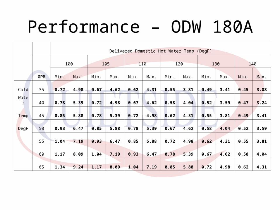
Performance – ODW 180A
Delivered Domestic Hot Water Temp (DegF)
GPM
100 105 110 120 130 140
Min. Max. Min. Max. Min. Max. Min. Max. Min. Max. Min. Max.
Cold 35 0.72 4.98 0.67 4.62 0.62 4.31 0.55 3.81 0.49 3.41 0.45 3.08
Water 40 0.78 5.39 0.72 4.98 0.67 4.62 0.58 4.04 0.52 3.59 0.47 3.24
Temp 45 0.85 5.88 0.78 5.39 0.72 4.98 0.62 4.31 0.55 3.81 0.49 3.41
DegF 50 0.93 6.47 0.85 5.88 0.78 5.39 0.67 4.62 0.58 4.04 0.52 3.59
55 1.04 7.19 0.93 6.47 0.85 5.88 0.72 4.98 0.62 4.31 0.55 3.81
60 1.17 8.09 1.04 7.19 0.93 6.47 0.78 5.39 0.67 4.62 0.58 4.04
65 1.34 9.24 1.17 8.09 1.04 7.19 0.85 5.88 0.72 4.98 0.62 4.31
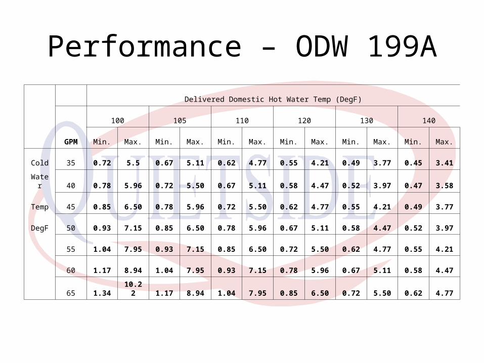
Performance – ODW 199A
Delivered Domestic Hot Water Temp (DegF)
GPM
100 105 110 120 130 140
Min. Max. Min. Max. Min. Max. Min. Max. Min. Max. Min. Max.
Cold 35 0.72 5.5 0.67 5.11 0.62 4.77 0.55 4.21 0.49 3.77 0.45 3.41
Water 40 0.78 5.96 0.72 5.50 0.67 5.11 0.58 4.47 0.52 3.97 0.47 3.58
Temp 45 0.85 6.50 0.78 5.96 0.72 5.50 0.62 4.77 0.55 4.21 0.49 3.77
DegF 50 0.93 7.15 0.85 6.50 0.78 5.96 0.67 5.11 0.58 4.47 0.52 3.97
55 1.04 7.95 0.93 7.15 0.85 6.50 0.72 5.50 0.62 4.77 0.55 4.21
60 1.17 8.94 1.04 7.95 0.93 7.15 0.78 5.96 0.67 5.11 0.58 4.47
65 1.3410.22 1.17 8.94 1.04 7.95 0.85 6.50 0.72 5.50 0.62 4.77

Don’t just select the largest unit
• Even though it is tempting don’t just select the largest unit available
• Unit modulation may cause it to cycle at combinations of very warm incoming water and low water flow rates
• Also we need to make sure that the gas supply piping is correctly sized

Water Requirements
• Water Quality TDS Total
(Total Hardness
Dissolved
Solids) Maximum 6.5 to Up to Up to Up to Up to Up to Up to Up to Up to
Levels 8.5 500 ppm 200 ppm 0.2 ppm 250 ppm 1.0 ppm 0.3 ppm 0.05 ppm 5 ppmor 11.7grains
hardness
Copper Iron Manganese ZincDescription PH Aluminum Chlorides
These are the maximum values of the minerals in the waterHaving higher levels of these minerals can cause furring of the Heat Exchangersplus reduced efficiency

Water Requirements
• What to do about Water Quality
Service the unit (frequency dependant on water quality)
Or
Treat the water before it enters the water
Several different methods available over the counter

What do you get included?• Unit, set up for Natural
Gas operation
• Unit Controller
• Vent Termination kit, including co-axial flue, termination kit
• Isolation kit, includes Ball Valves, purge valves and ASME rated Pressure Relief Valve

What do you supply? • Gas piping, minimum ¾”
but selected for the Btu/h input capacity of the unit
• Schedule 40 PVC venting including Elbow and Bird Screen for vent
• Water piping from cold supply to unit and hot water piping to house
• 115V power, power wiring and thermostat wire to the controller(s)

Installation basics
• Indoor location only – the unit doesn’t like getting wet
• Minimum ambient temperature above 45 DegF, even with the freeze protection heaters
• Respect the necessary clearances to the front, sides, back, top and bottom of the unit

Gas Piping - Basics Natural Gas Pressure - Primary• 3.5” to 10.5” WC
LP Gas Pressure - Primary• 8” to 13” WC
• Gas meter must be capable of supplying total gas demand for the residence
• Gas pressures below the minimum will reduce performance
• Ensure gas pressure does not drop on initial start or unit may become noisy in combustion
• Do not use Flexible Gas Lines unless they are rated for a Minimum capacity of 250,000 Btu/h

Gas Piping - Basics
• Gas pipe size is determined by two factors
1. Max Input capacity of the appliance connected
2. Distance from the Gas meter
The larger the appliance and the further away from the meter the larger the gas pipe size
Gas Piping - Sizing • Determine where the unit will be installed
on the gas pipe
• Closer to the meter is always better
• If unit is located at furthest point from the meter considering running a dedicated stick of black iron directly from the meter to the ODW

Gas Piping - Basics
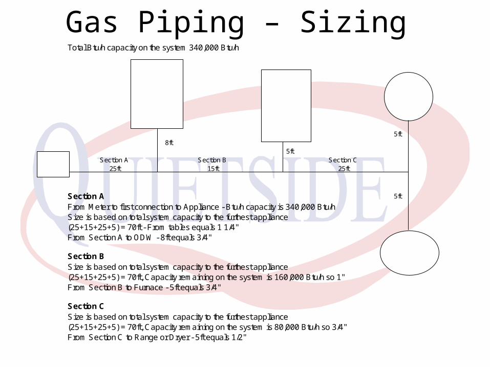
Gas Piping – Sizing Total Btu/h capacity on the system 340,000 Btu/h
5ft8ft
5ftSection A Section B Section C
25ft 15ft 25ft
Section A 5ft
From Meter to first connection to Appliance - Btu/h capacity is 340,000 Btu/hSize is based on total system capacity to the furthest appliance(25+15+25+5) = 70ft - From tables equals 1 1/4"From Section A to ODW - 8ft equals 3/4"
Section BSize is based on total system capacity to the furthest appliance(25+15+25+5) = 70ft, Capacity remaining on the system is 160,000 Btu/h so 1"From Section B to Furnace - 5ft equals 3/4"
Section CSize is based on total system capacity to the furthest appliance(25+15+25+5) = 70ft, Capacity remaining on the system is 80,000 Btu/h so 3/4"From Section C to Range or Dryer - 5ft equals 1/2"
GAS METER
180,000 Btu/hODW-180A
35,000 Btu/h
DRYER
80,000 Btu/hFURNACE
45,000 Btu/h
RANGE

Gas Piping - Sizing Total Btu/h capacity on the system 340,000 Btu/h
5ft8ft
5ftSection A Section B Section C
25ft 15ft 25ft
Section A 5ft
From Meter to first connection to Appliance - Btu/h capacity is 340,000 Btu/hSize is based on total system capacity to the furthest appliance(25+15+25+5) = 70ft - From tables equals 1 1/4"From Section A to Dryer - 8ft equals 1/2"
Section BSize is based on total system capacity to the furthest appliance(25+15+25+5) = 70ft, Capacity remaining on the system is 305,000 Btu/h so 1 1/4"From Section B to Furnace - 5ft equals 3/4"
Section CSize is based on total system capacity to the furthest appliance(25+15+25+5) = 70ft, Capacity remaining on the system is 225,000 Btu/h so 1"From Section C to Range, 5ft equals 1/2"From Section C to ODW, 5ft equals 3/4"
GAS METER
180,000 Btu/hODW-180A
35,000 Btu/h
DRYER
80,000 Btu/hFURNACE
45,000 Btu/h
RANGE

Gas Piping - Sizing
• Connection from the stick to the unit
• If using flexible gas piping make sure it is capable of supplying a minimum of 250,000 Btu/h
• Always install a gas shut off valve and drip leg adjacent to the unit

Hanging the unit on the wall• Remove unit from Carton
• Unit installs on a hanging bracket (supplied) mounted to studs or wall brace
• CANNOT be installed on a combustible wall. Use non combustible backing plate e.g. Durarock or 24g sheet metal

Water Piping (cont)
• Cold Water inlet including strainer
• Hot Water outlet

Water Piping• 2 Connections – Cold In, Hot
Out
• ¾” Isolation Valve package included with the unit
• Ball Valves, Purge Valves, 150 Psi Pressure Relief Valve ¾” threaded connection
• ODW 099/120 includes a ½” adaptor from the isolation valve kit – but ¾” connection to the house
Water Piping (cont)
• Isolation Valve kit includes a Pressure Relief Valve to meet code requirements, rated at 150 psi
• Pipe PR Valve to building drain or other suitable area
• A Temperature Relief Valve is not required unless local codes mandate it – however if one is installed do not install with the probe directly in the water flow
Water Piping (cont)
• Unit is designed for Potable water only, therefore all piping should be suitable – Copper, PEX (where allowed by code), etc
• If the unit is providing potable hot water, it cannot be connected by code to a heating system using non-potable components or chemicals
• Make sure cold water feed pressure is above 14 Psi and below 125 Psi – if outside that range installing a pump or de-pressurizing pump


I want “Instant” Hot Water!
• Recirculation – Based on time or temperature
• Pump sized to push water through the unit to remove the cold plug contained in the lines
• Taco Dmand system
• Unit takes 3 seconds to go from sensing flow to firing. This is a big advantage over other Tankless Water Heaters, reduces cold water sandwiching

Condensate Piping
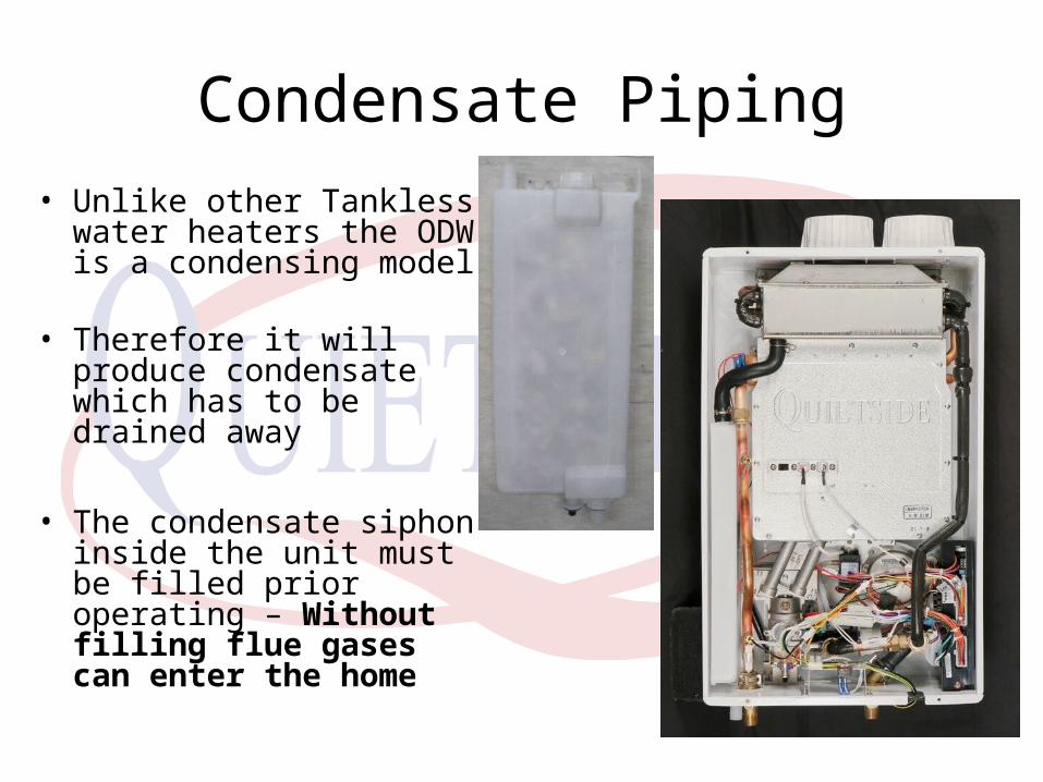
• Unlike other Tankless water heaters the ODW is a condensing model
• Therefore it will produce condensate which has to be drained away
• The condensate siphon inside the unit must be filled prior operating – Without filling flue gases can enter the home
Useful advantages of condensing
• Lower Flue gas temperatures
• ODW maximum flue gas temperature is 136 DegF
• This allows venting in Schedule 40 PVC in all states and provinces, with zero clearance
• This is a big advantage over other Tankless Water Heaters, required to be vent in single wall stainless steel (which is not B vent)
Venting
• Description – Sealed combustion or Direct Vent
• Both Intake and Exhaust air must be provided to the unit
• Ø3” for 099 & 120
• Ø4” for 180 & 199
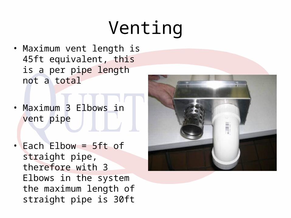
Venting• Maximum vent length is
45ft equivalent, this is a per pipe length not a total
• Maximum 3 Elbows in vent pipe
• Each Elbow = 5ft of straight pipe, therefore with 3 Elbows in the system the maximum length of straight pipe is 30ft

Vent Connection on unit
• Plastic connection to accept either 3” or 4” vent pipe directly on top of the unit
• Approved PVC cement is required to bond the two together
• Use Hi Temp Silicone seal on the joint to ensure a full seal


Vent Piping• Always slope flue pipe back to
the unit – 1” in 12” minimum
• This allows any condensate produced in the flue pipe to return to the unit and drain through the condensate system
• Prevents growth of ice stalactites on the outside of the building penetrations through the building required
• Zero Clearance to combustibles

Termination Location• Vent Termination must be located
• Minimum of 12” above grade OR 12” above anticipated snowfall level
• 10” below eaves or building overhang
• 12” from windows, openings and other venting
• 24” clearance in front of the termination
• Away from plants, trees, animals

Wall Penetration• Two penetrations through the building required
• Z Dimension ODW 099-120 is 4 ½”• Z Dimension ODW 180-199 is 6”

Flue Termination• Flue termination
included – Stainless Steel
• Attach to the Flue pipe with the connection provided
• Seal around PVC joint and termination with hi temperature Silicone
Seal

Termination Cover• Once Flue termination is connected attach the
Termination cover to the building
• Slide over the flue and Intake pipes (larger opening is for the air intake)
• Screw to wall with 4 screws – provided
• Seal around flue termination with high temperature Silicone
Inlet Air
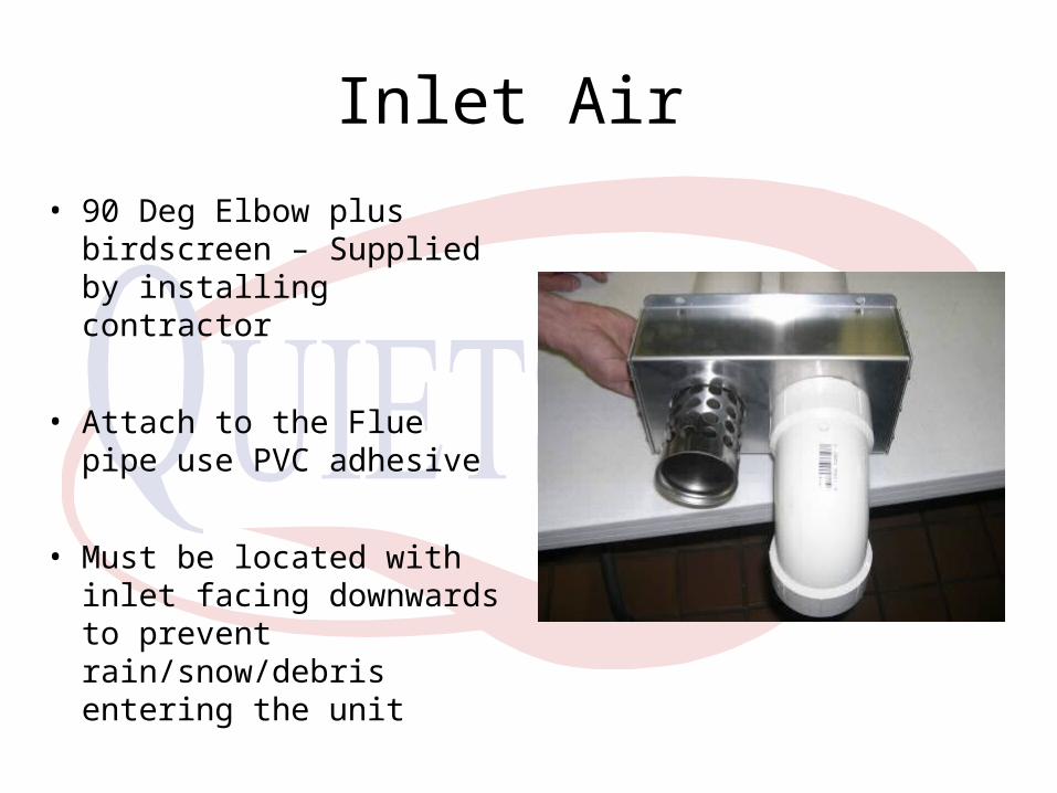
• 90 Deg Elbow plus birdscreen – Supplied by installing contractor
• Attach to the Flue pipe use PVC adhesive
• Must be located with inlet facing downwards to prevent rain/snow/debris entering the unit

Other than Sidewall
• Unit can be vented
• Flue and Intake Air from separate barometric planes
• i.e – Flue gas vented through one wall, with Intake supplied via a penetration on a different wall

Vertical
• 2 x 45 Deg angles on the flue are mandatory
• Prevents any pooling of condensate in the flue pipe
• 2 x 90 Deg Elbows required on the Intake pipe
• Note clearances – if in areas of snowfall ensure air intake is 12” above anticipated snowfall accumulation

Power Wiring
• Unit is powered from a 115V, 15A dedicated and grounded power supply
• Unit has 2 x 3 Amp glass style fuses to prevent damage occurring to the microprocessor or other components dues to power issues
• Wire power to unit per local codes regarding connection to the wiring of the unit
• Currently this will possibly include adding a junction box adjacent to the unit, depending on local codes

Unit Control
• Standard control is via a wired controller which can be mounted either adjacent to the water heater or in a bathroom
• An optional Priority controller is available for a total of 2 controls on the system

Controller
Up and DownButtons set therequired hot watertemperature from the unit
On/OffButton turns theUnit On or Offas required
Priority buttonallows the secondthermostat to override the main
Temperature canbe set from 98-114DegF in 2 DegF increments or 120, 130, 140, 150 & 160 DegF settingsFactory default is 104

Optional Priority Controller
Up and DownButtons set therequired hot watertemperature from the unit different to that of the maincontroller
On/OffButton turns theUnit On or Offas required
Priority Light is lit.This allows the Second thermostat to override the mainUse if you want a hotter shower thanallowed for a kid’sshower
Temperature canbe set from 98-114DegF in 2 DegF increments or 120, 130, 140, 150 & 160 DegF settingsFactory default is 104

Wiring Standard Controller
2 Wire ConnectionYellow WiresThermostat WireNo Polarity20V DC

Wiring Priority Controller2 Wire ConnectionYellow WiresThermostat Wire“Piggy Back”No Polarity20V DC

Ready for Start Up?
• Water Piping – Flushed, Leak Free?
• Gas Piping – Purged, Leak Free?
• Electrical/Control wiring – Ready to go?
• Dip Switches set – Huh?

Dip Switches?
• Dip 1 : LP or Natural
• Dip 2 : Vent length
• Dip 3 : Program
• Dip 4 : Max Fire
• Dip 5 : Min Fire

Dip Switch Settings
• #1 : Fuel Type
Switch ON for conversion to LP from Natural Gas
LP conversion requires replacement of burner assembly
Model ODW 99 ODW 120 ODW 180 ODW 199
Burners 15 EA 20 EA
SizeLNG : Φ1.48 * 5EA / Φ1.38 * 10EA
LPG : Φ1.12 * 5EA / Φ1.03 * 10EA
LNG : Φ1.65 * 20EA
LPG : Φ1.20 * 20EA

LP Gas Conversion
• Replace burner manifold assembly with one specific to LP
• Change dip switch #1 to ON - tell the unit that it is now LP

Dip Switch Settings
• #2 Vent Length
• Switch OFF for Vent lengths less than 16ft
• Switch ON for Vent lengths greater than 16ft

Dip Switch Settings
• #3 Set Up Mode
• Switch to ON to put the unit into set up mode, change display, check operating parameters

Dip Switch Settings
• #4 & #5
• Minimum and Maximum firing rate
• Locks the unit in either Minimum or Maximum firing rate

Unit Start Up
• Once the system is set up, open valves on water connections, allow unit to fill with water and flow water through the unit for 5 minutes
• Open Gas Valve and check for leaks
• Power up unit, set temperature and open up faucets to allow unit to start and produce hot water
Unit Start Up
• Unit should now start, operate unit until a steady flow of water is seen at all faucets, showing that air has been removed from the system
• Unit should now control to flow and set temperature
• If a fault code appears………….

Code Fault Description Code Fault Description
A0 Flow Control Valve (FCV) Faulty A8 Pseudo Flame
A1 By-pass Control Valve (BCV) A9 Freeze Protection
In Combustion Fan Failure AA Inlet Temp Sensor Failure
A3 Communication Error Ab HX Temp Sensor Failure
A4 Over Heat Ac Delivered Water Temp Sensor
A5 Outlet Water Temp Ad Condensate
A6 Ignition Failure AE Air Pressure Switch
A7 Gas Valve Failure AF
Fault Codes

Fault Codes
• All Fault codes with the exception of A5 are a hard lockout, meaning that the power to the unit has to be cycled to reset the system
• If the wired remote is broken, removing it and crossing the wires together will allow the unit to run, but with the setpoint of 104 DegF

A0 – Flow Control Valve Error• Flow control Valve has 2
functions, sense the flow rate and control to flow to maintain the set temperature
• If the flow rate demand exceeds the unit capacity the valve will throttle to maintain set temperature, rather than reducing the delivered temperature and maintain flow

A0 – Flow Control Valve Error• A0 will show if the
micro commands the solenoid to open or close and it does not, OR
• If the signal from the flow sensor cannot be read by the micro
• Solution – check connections, replace valve

A1 – Bypass Valve Error
• Bypass Valve also has 2 functions, act as a mixing valve to provide a stable delivered temperature and also protect the HX from over condensing
• Thx > Td + 18~27°F

A1 – Bypass Valve Error
• A1 will show if the micro commands the valve to open or close and it does not
• Both valves are worm drive solenoid style similar to the EEV on a Samsung unit
• Solution – Check connections,

A2 – Combustion Fan Error
• Combustion Fan is a BLDC type fed with 4 wires from the micro
• Fan speed varies with capacity, signal is from 5V-45V DC
• Fan signals back to the micro, it’s speed and rotation as part of the feedback loop

A2 – Combustion Fan Error• A2 fault is caused by the fan either
not operating, going backwards or not sending a feedback signal to the Micro
• White wire is feedback, should be >100Hz with fan running
• Black ~ Yellow is 12V DC, if no voltage is present = faulty micro
• Black ~ Red is variable 5V – 45V DC, with the motor disconnected should read 45V DC, connected dependant on capacity
• Solution : Check for signal, check for rotation (no winds), check motor resistance, replace either fan or micro

A3 – Communication error
• Micro and Wired remote communicate together for set point error codes etc
• DC voltage 20V DC
• A3 is shown when Micro and Controller cannot communicate
• Solution : Check wiring between units (not polarity sensitive), replace controller first
A4 – Over Heat Error
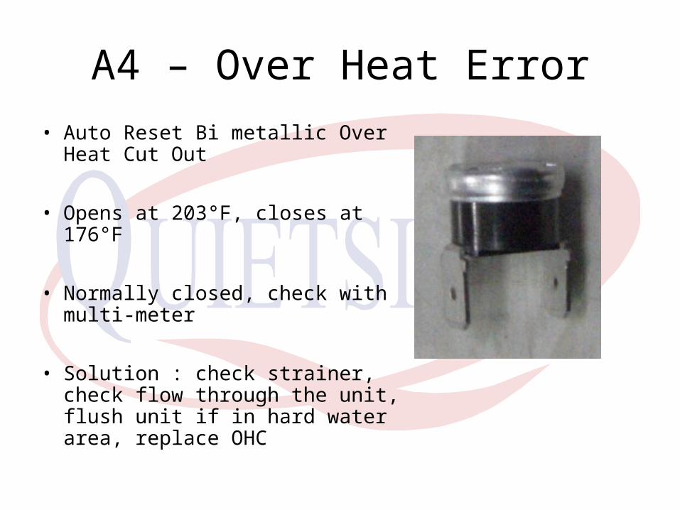
• Auto Reset Bi metallic Over Heat Cut Out
• Opens at 203°F, closes at 176°F
• Normally closed, check with multi-meter
• Solution : check strainer, check flow through the unit, flush unit if in hard water area, replace OHC
A5 – Outlet Water Temp Error
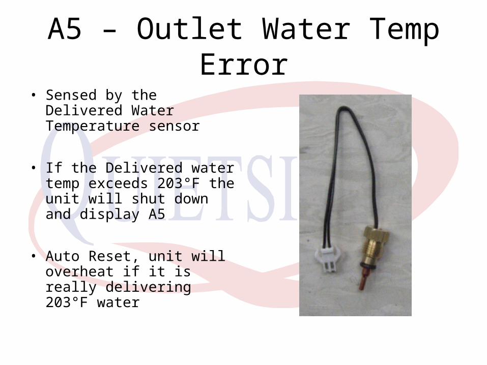
• Sensed by the Delivered Water Temperature sensor
• If the Delivered water temp exceeds 203°F the unit will shut down and display A5
• Auto Reset, unit will overheat if it is really delivering 203°F water
A6 – Ignition Failure
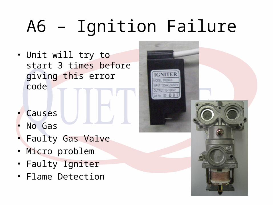
• Unit will try to start 3 times before giving this error code
• Causes• No Gas• Faulty Gas Valve• Micro problem• Faulty Igniter• Flame Detection

A6 – Ignition Failure
• No Gas
• Remove Philips head screw check for gas pressure
• If none check SV1 for power (120V AC) and check gas supply
• Also there is a master On/Off switch in the unit controlling output to the gas valve, make sure that is ON
• Check gas supply outside unit, especially for LP fuelled units

A6 – Ignition Failure
• Faulty Gas Valve
• Check voltage to SV1, SV2 and SV3 for 120V AC
• If voltage is present, check resistance of SV1, SV2, SV3
• SV1 = 1650Ω• SV2 = 1650Ω• SV3 = 1650Ω

A6 – Ignition Failure
• Faulty Gas Valve
• Check Voltage to modulating coil should be between 5V DC to 15V DC (Min fire to Max Fire)
• MV resistance is 77Ω
• If there is zero volts at the Modulating valve gas pressure should still read approx 3/8” WC if SV1 is open
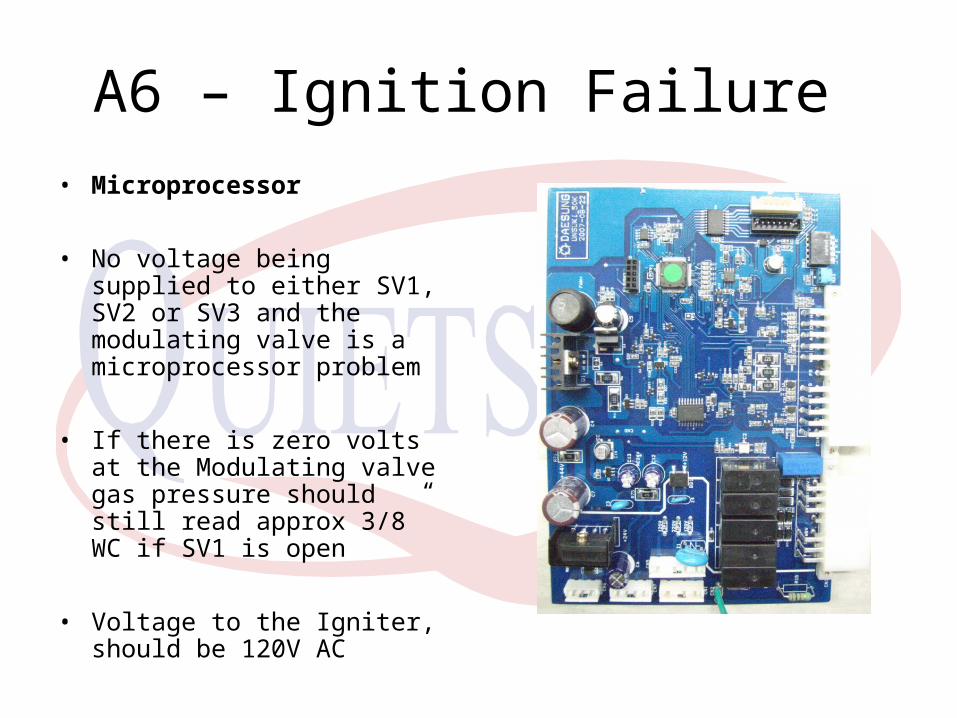
A6 – Ignition Failure
• Microprocessor
• No voltage being supplied to either SV1, SV2 or SV3 and the modulating valve is a microprocessor problem
• If there is zero volts at the Modulating valve gas pressure should still read approx 3/8” WC if SV1 is open
• Voltage to the Igniter, should be 120V AC

A6 – Ignition Failure
• Faulty Igniter
• Check voltage to the igniter, primary voltage should be 120V AC
• Secondary voltage is 15kV to 18kV
• Check Primary/Secondary resistance to ground
• Primary : 1MΩ• Secondary : 720Ω

A6 – Ignition Failure
• Flame Detection
• Micro sends a 24V AC signal to the flame detector
• No Flame is a 0V signal back to the micro
• If a Flame is present, should read 0.3µA ~ 1.2µA to ground

A7 – Gas Valve Error • Faulty Gas Valve
• Failure of SV1 or SV2 to open
• Check voltage to SV1, SV2 and SV3 for 120V AC
• If voltage is present, check resistance of SV1, SV2
• SV1 = 1650Ω• SV2 = 1650Ω
• If voltage is not present, problem lies with the Micro
• Solution : Replace whichever component is faulty

A8 – Pseudo Flame
• Pseudo Flame is where the unit receives a signal from the flame detector either prior to SV1, 2 or 3 opening OR detecting a flame after the unit has shut down
• Either faulty flame sensor or Microprocessor, but we can check to make sure no gas is leaking through the gas valve solenoids

A9 – Freeze Protection
• Freeze Protection occurs when the cold water temperature entering the unit is below 23°F OR -5C
• This is to protect the unit against freezing and also against over production of condensate
• Unit will restart when the incoming cold water is above 32 DegF
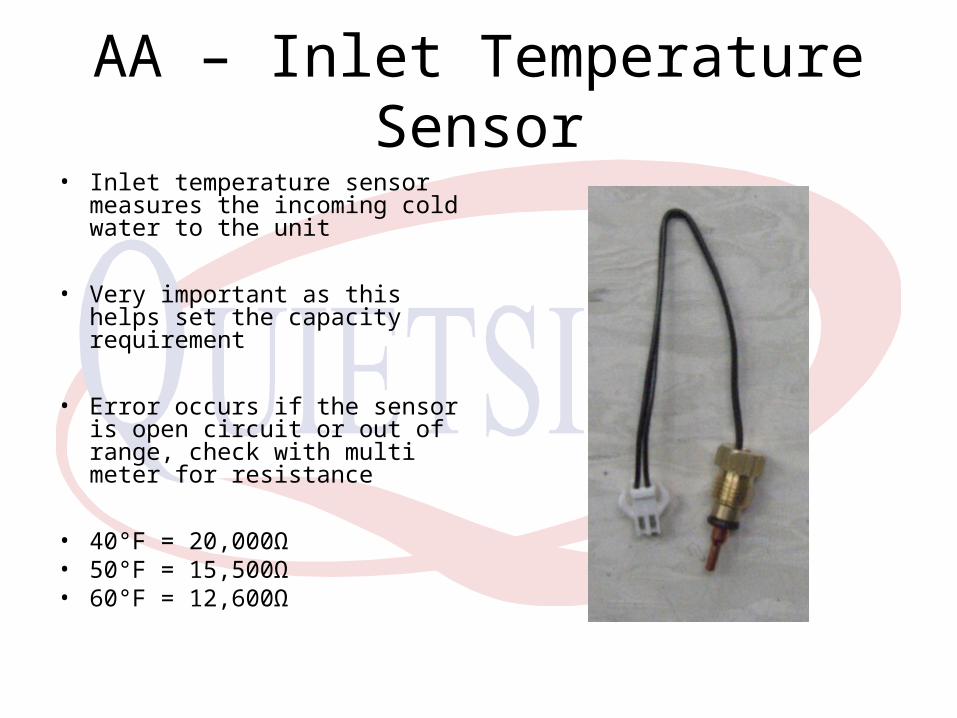
AA – Inlet Temperature Sensor• Inlet temperature sensor
measures the incoming cold water to the unit
• Very important as this helps set the capacity requirement
• Error occurs if the sensor is open circuit or out of range, check with multi meter for resistance
• 40°F = 20,000Ω• 50°F = 15,500Ω• 60°F = 12,600Ω

Ab – HX Temperature Sensor• HX temperature sensor measures
the water temp leaving the heat exchangers
• Very important as this sets the By Pass valve opening for a stable delivered water temperature
• Should measure about 15-20°F higher than delivered water temperature
• Error occurs if the sensor is open circuit or out of range, check with multi meter for resistance
• 120°F = 3,400Ω• 140°F = 2,500Ω• 160°F = 1,800Ω

Ac – Delivered Water Temp Sensor
• Delivered water temperature sensor measures the final delivered water temperature to the faucet
• This is the temperature seen by the end user
• Error occurs if the sensor is open circuit or out of range, check with multi meter for resistance
• 104°F = 4,900Ω• 110°F = 4,200Ω• 120°F = 3,400Ω
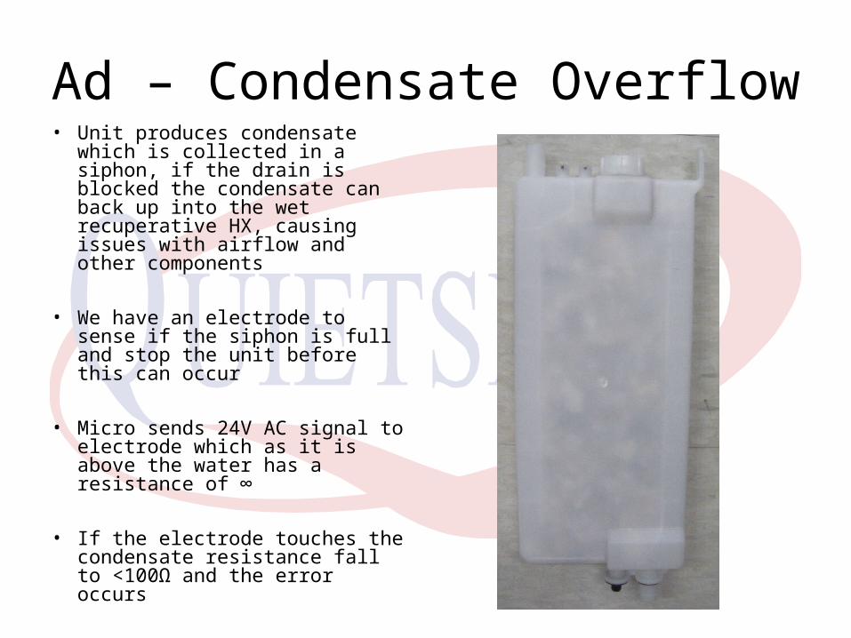
Ad – Condensate Overflow• Unit produces condensate
which is collected in a siphon, if the drain is blocked the condensate can back up into the wet recuperative HX, causing issues with airflow and other components
• We have an electrode to sense if the siphon is full and stop the unit before this can occur
• Micro sends 24V AC signal to electrode which as it is above the water has a resistance of ∞
• If the electrode touches the condensate resistance fall to <100Ω and the error occurs

AE – Air Pressure Switch
• Monitors flue pressure across the unit, compared to atmospheric pressure
• Normally closed switch, opens on failure
• ODW099 & 120 opens at ½” WC
• ODW180 & 199 opens at 5/8” WC
• Control voltage 5V DC

AE – Air Pressure Switch• Two hoses • #1 – Back of cabinet for
atmospheric pressure, very important that no insulation be applied to the back or the unit and the unit is not mounted flush to the wall
• #2 – Fan Throat, upper port on the back of the fan
• Failure can be due to, blocked flue, flue over max length, vent terminal facing prevailing winds, Condensate backed up into HX’s
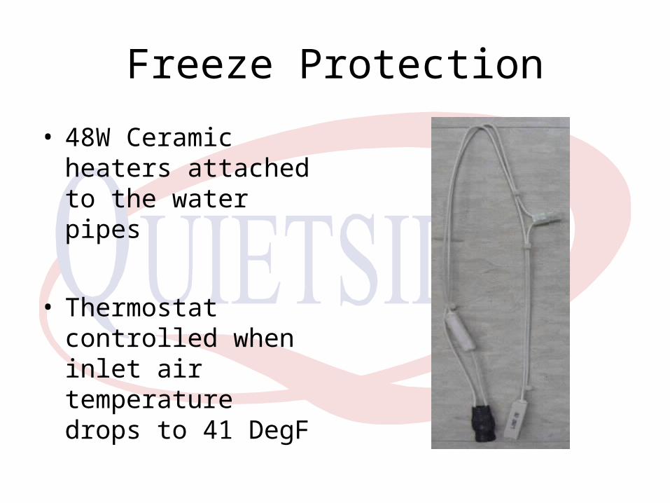
Freeze Protection
• 48W Ceramic heaters attached to the water pipes
• Thermostat controlled when inlet air temperature drops to 41 DegF
Warranty
Standard Warranty Residential usage
• 12 Years Heat Exchanger
• 5 Years Parts
• No labor allowance as standard

Tech Support
1-562 699 6066 x 3 – West Coast
1-717 243 2535 – East Coast
Website – www.quietside.com

Thank you
Any Questions