quickmanual - schneider electric motion usa
TRANSCRIPT

QuickMANUAL
HardwareSoftware
Applications

The information in this book has been carefully checked and is believed to be accurate; however, no responsibility is assumed for inaccuracies.
Intelligent Motion Systems, Inc., reserves the right to make changes without further notice to any products herein to improve reliability, function or design. Intelligent Motion Systems, Inc., does not assume any liability arising out of the application or use of any product or circuit described herein; neither does it convey any license under its patent rights of others. Intelligent Motion Systems and are trademarks of Intelligent Motion Systems, Inc.
Intelligent Motion Systems, Inc.’s general policy does not recommend the use of its products in life support or aircraft applications wherein a failure or malfunction of the product may directly threaten life or injury. Per Intelligent Motion Systems, Inc.’s terms and conditions of sales, the user of Intelligent Motion Systems, Inc., products in life support or aircraft applications assumes all risks of such use and indemnifies Intelligent Motion Systems, Inc., against all damages.
TM
MicroLYNX MQuick Manual Revision R051205Copyright © 2006 Intelligent Motion Systems, Inc., All Rights Reserved
Change Log
Date Revision Changes

1
Table Of ContentsSection 1: Introduction To The MicroLYNX ............................................ 5Electrical Specifications ................................................................................................................6
Communications Specifications ........................................................................................7Mechanical Specifications ................................................................................................. 7Environmental Specifications ............................................................................................ 7Connector Information .......................................................................................................8Mounting Information ........................................................................................................ 9MicroLYNX Terminology Explained...................................................................................9Shopping List ...................................................................................................................10
Section 2: Connecting Power................................................................. 11Tools and Equipment Required ....................................................................................... 11How to Connect Power....................................................................................................11
Section 3: Connecting A Motor .............................................................. 13Tools and Equipment Required ....................................................................................... 13Recommended Stepping Motors ..................................................................................... 13How to Connect the Motor .............................................................................................. 13
Section 4: Connecting Communications .............................................. 17Tools and Equipment Required ....................................................................................... 17Connecting Communications .......................................................................................... 17
Section 5: Establishing Communications............................................. 20Tools and Equipment Required ....................................................................................... 20Installing the IMS Terminal Software .............................................................................. 20Using the IMS Terminal Software ...................................................................................21
Section 6: Controlling Motor Current .................................................... 24Current Control Variables ................................................................................................24
Section 7: Setting The Motor Resolution .............................................. 25Setting the Motor Resolution Exercise ............................................................................25
Section 8: Using The Isolated Digital I/O .............................................. 26The Isolated Digital I/O Defined ......................................................................................26Setting the Pull-up Voltage .............................................................................................. 27The Input Output Setup Variable ..................................................................................... 28The IO Variable ............................................................................................................... 32Setting the Digital Filtering for the I/O .............................................................................34
Section 9: Expanding The MicroLYNX .................................................. 35MicroLYNX Expansion Modules ......................................................................................35Choosing the Expansion Modules for Your Application ..................................................35Expanding the Isolated Digital I/O ...................................................................................36The High-Speed Differential I/O Module ......................................................................... 38The Analog Input/Joystick Module .................................................................................. 46The Isolated Communications Module ............................................................................50The Analog Output Module .............................................................................................51The 12 Channel Isolated Digital I/O Module ...................................................................53
2
Section 10: MicroLYNX Software Components .................................... 56LYNX Software Components ..........................................................................................56Variables .........................................................................................................................56Commonly Used Variables ..............................................................................................56Instructions ......................................................................................................................59Flags ................................................................................................................................65Keywords.........................................................................................................................65
Section 11: MicroLYNX Programming................................................... 66Introduction to MicroLYNX Programming........................................................................66Program Development Steps ..........................................................................................67Program Samples ...........................................................................................................69
Section 12: Sample Applications........................................................... 73Feed Cut 1.......................................................................................................................73Read and Feed................................................................................................................76AND - OR ........................................................................................................................78On-The-Fly ......................................................................................................................79Registration .....................................................................................................................81Traverse ..........................................................................................................................84
Appendix A: Software Summary ........................................................... 87Appendix B: Troubleshooting ................................................................ 93
Beginning to Troubleshoot ..............................................................................................93Troubleshooting Communications ...................................................................................93Troubleshooting Software ...............................................................................................93Contacting Application Support .......................................................................................95
Appendix C: Error Table ......................................................................... 96Appendix D: Recommended Cable Configurations ............................. 99
List of FiguresFigure 1.1 Dimensional Information ...............................................................................7Figure 1.2 Connector Pin Configuration ........................................................................8Figure 1.3 Panel Mounting the MicroLYNX ...................................................................9Figure 2.1 MicroLYNX Power Connection ...................................................................12Figure 3.1 8 Lead Motor, Series Connection ...............................................................14Figure 3.2 8 Lead Motor, Parallel Connection ............................................................. 15Figure 3.3 6 Lead Motor, Full Coil Connection ............................................................15Figure 3.4 6 Lead Motor, Half Coil Connection ............................................................16Figure 3.5 4 Lead Motor Connection ...........................................................................16Figure 4.1 MicroLYNX with IMS Communications Cable ............................................17Figure 4.2 RS-232 Interface Connection .....................................................................18Figure 4.3 RS-485 Interface Connection .....................................................................19Figure 5.1 IMS Terminal Main Window........................................................................21Figure 5.2 IMS Terminal Communications Setup Window .......................................... 22Figure 5.3 IMS Terminal Download Dialog .................................................................. 23Figure 5.4 IMS Terminel Upload Dialog .......................................................................23Figure 6.1 Motor Current Control Variables .................................................................24Figure 8.1 Isolated I/O Pin Configuration.....................................................................26Figure 8.2 Isolated I/O Applications .............................................................................27Figure 8.3 The IOS Variable Settings ..........................................................................28Figure 8.4 IOS Exercise #1 .......................................................................................... 29

3
Figure 8.5 IOS Exercise #2A .......................................................................................29Figure 8.6 IOS Exercise #2B .......................................................................................30Figure 8.6 I/O Variable Exercise Setup .......................................................................33Figure 9.1 Installing the Isolated Digital I/O Module ....................................................37Figure 9.2 The Isolated Digital I/O Module, Bottom View ............................................37Figure 9.3 Powering Multiple Isolated Digital I/O Modules ..........................................38Figure 9.4 Installing the High-Speed Differential I/O Module.......................................39Figure 9.5 Clock Functions ..........................................................................................40Figure 9.6 IOS Settings for the High-Speed Differential I/O ........................................41Figure 9.7 Differential Encoder Connection .................................................................42Figure 9.8 Differential I/O Connections for Following ..................................................45Figure 9.9 Installing the Analog Input/Joystick Module................................................47Figure 9.10 Analog Input Module Exercise Connection .................................................48Figure 9.11 Installing the Isolated Communications Module .........................................50Figure 9.12 Installing the Analog Output Module ...........................................................51Figure 9.13 Installing the 12 Channel Isolated I/O Module ............................................54Figure 9.14 12 Channel I/O Module Pull-Up Switches ..................................................54Figure 9.15 Powering Multiple Isolated Digital I/O Modules ..........................................55Figure 10.1 Setting the MUNIT Variable ........................................................................57Figure 10.2 Motion Profile Showing Basic Parameters .................................................58Figure 10.3 MOVA Instruction Modes............................................................................60Figure 11.1 Flowchart Used for Program Planning ........................................................67Figure 12.1 Feed Cut Application ..................................................................................73Figure 12.2 Feed Cut Application Flowchart ..................................................................74Figure 12.3 Read and Feed Application ........................................................................76Figure 12.4 Read and Feed Application Flowchart ........................................................76Figure 12.5 On-The-Fly Application ...............................................................................79Figure 12.6 On-The-Fly Application Flowchart ..............................................................80Figure 12.7 Registration Application ..............................................................................81Figure 12.8 Registration Application Flowchart .............................................................82Figure 12.9 Traverse Application ...................................................................................84Figure 12.10Traverse Application Flowchart ..................................................................85
List of TablesTable 4.1 RS-232 Interface Connection .....................................................................18Table 4.2 RS-485 Interface Connection .....................................................................19Table 7.1 Microstep Resolution Settings ....................................................................25Table 8.1 Binary State of Outputs ..............................................................................33Table 8.2 IOF Settings ................................................................................................34Table 9.1 MicroLYNX Expansion Module Configurations ...........................................36Table 9.2 Isolated Digital I/O Group and Line Locations ............................................36Table 9.3 High Speed Differential Electrical Characteristics ......................................39Table 9.4 High Speed Differential I/O Pinout ..............................................................39Table 9.5 The Four Clocks and Their Default Line Placement ...................................40Table 9.6 Expansion Slot #2 Encoder Connections ...................................................42Table 9.7 Analog Input Module Specifications ...........................................................46Table 9.8 Analog Input/Joystick Module Pin Configuration ........................................46Table 9.9 RS-232 Pinout ............................................................................................50Table 9.10 RS-485 Pinout ............................................................................................50Table 9.11 Analog Output Module Pinout .....................................................................51Table 9.12 12 Channel Isolated I/O Module Pinout ......................................................53

4
This Page Intentionally
Left Blank

5
Introduction To The MicroLYNX
The MicroLYNX is a powerful machine control systemwhich combines a bipolar microstepping driver with anexpandable programmable controller in a compactpanel mounted assembly.
With the addition of differential I/O modules, the Micro-LYNX has the capability of driving two additional axessequentially or driving a following axis electronicallygeared to the on-board driver.
The MicroLYNX includes two independent communica-tion ports. It will accept commands from either port anddirect output to either as well. A system may be config-ured to use COMM Port 1 to communicate to a host PCor PLC while using the COMM Port 2 to communicatewith an operator interface or additional MicroLYNXsystems.
The MicroLYNX comes in two output power ranges(12-48 VDC, 3 Amp RMS-4Amp Peak, and 24-75 VDC, 5 Amp RMS-7 Amp Peak) to fit a varietyof motor sizes. Features such as 5 to 24VDC isolated I/O, multiple communication types, andnumerous expansion options make the MicroLYNX an effective and powerful machine controlsolution.
Plug-on accessory modules allow control systemdesigners to tailor the MicroLYNX System to theirneeds with minimal cost. The MicroLYNX may be fieldupgraded by simply removing the side cover andadding expansion modules.
The MicroLYNX software is upgradeable by using theIMS Terminal Software. Updates are posted on theIMS web site at www.imshome.com and may bedownloaded. This allows older units the ability to usenew features and expansion modules as they becomeavailable.
This Quick Guide is a step-by-step usage guide for theMicroLYNX. While not intended to replace the productmanual, it is essential in acquiring a thorough under-standing of the MicroLYNX System. This Quick Guideprovides the user with detailed connection and usageexamples for the MicroLYNX and its associated expansion modules, as well as the most com-monly used components of the MicroLYNX instruction set. It also includes an introduction toMicroLYNX programming.
1

6
E l e c t r i c a l S p e c i f i c a t i o n s
Powe r S upp l y R equ i r emen t s
See Section 2: Connecting Power for the recommended power supplies.
P o w e r S u p p l y Vo l t a g e f o r :
MicroLYNX - 4 (MX-CS100-401)................................. +12 to +48VDCMicroLYNX - 7 (MX-CS100-701)................................. +24 to +75VDC
P o w e r S u p p l y O u t p u t C u r r e n t f o r :
MicroLYNX - 4 (MX-CS100-401)................................. 2A Typ., 4A PeakMicroLYNX - 7 (MX-CS100-701)................................. 3A Typ., 7A Peak
Actual requirements depend on application and programmable current setting.
Moto r D r i v e
See Section 3: Connecting a Motor for recommended motors; Section 6: Controlling the MotorCurrent and Section 7: Setting the Motor Resolution for details on the following specifications.
Motor Type .................................................................... 2/4 Phase bipolar stepperMotor Current (Software Programmable)
MicroLYNX - 4 ................................................ to 4A PeakMicroLYNX - 7 ................................................ to 7A Peak
Microstep Resolution (# of settings) ............................ 14Steps per Revolution (1.8° Motor) ............................... 400, 800, 1000, 1600, 2000,
3200, 5000, 6400, 10000,12800, 25000, 25600, 50000,51200.
I s o l a t e d D i g i t a l I /O
See Section 8: Using the Isolated Digital I/O for usage instructions.
Number of I/O .............................................................. 6 std, expandable to 24Input Voltage ............................................................... +5 to +24VDCOutput Current Sink .................................................... 350mA per LineInput Filter Range (Programmable) ............................ 215Hz to 21.5kHzPull-up Resistors ......................................................... 7.5 kΩ switchablePull-up Voltage (max)
Internal (Not an Output) .................................. +5VDCExternal .......................................................... +24VDC
Protection .................................................................... Over temp, short circuit,inductive clamp
Isolated Ground........................................................... Common to the 6 I/O lines

7
C o m m u n i c a t i o n s S p e c i f i c a t i o n s
See Sections 4 & 5 for connection and usage details.
Interface TypeCOMM 1 ......................................................... RS-232COMM 2 ......................................................... RS-485
# Bits per Character .................................................... 8Parity ........................................................................... NoneHandshake .................................................................. NoneBAUD Rate .................................................................. 4800 to 38.4kbps (9600 Default)Error Checking ............................................................ 16 bit Check Sum (binary mode)Communication Modes ............................................... ASCII Text or BinaryIsolated Ground............................................................. Common to COMM 1 and 2
M e c h a n i c a l S p e c i f i c a t i o n s
Dimensions ................................................................. See figure 1.1# of Expansion Modules .............................................. 3Cooling ........................................................................ Built-in fanRecommended Mounting Hardware ........................... 2 #6 (M3.5) machine screwsMounting Screw Torque .............................................. 5 to 7 lb-in (0.60 to 0.80 N-m)
E n v i r o n m e n t a l S p e c i f i c a t i o n s
Ambient Operating Temperature ................................ 0 to 50°C*Storage Temperature .................................................. -20 to 70°CHumidity ...................................................................... 0 to 90% non-condensing* Can be duty cycle dependent.
Figure 1.1: Dimensional Information, Dimensions in Inches (mm)

8
Figure 1.2: Connector Pin Configuration
C o n n e c t o r I n f o r m a t i o n
MicroLYNX ConnectionsCommunications: 7 Position PhoenixI/O: 10 Pin Header
I/O LINE 21: PIN 1VPULLUP: PIN 3
FAULT + INPUT: PIN 5FAULT - INPUT: PIN 7
I/O Ground (Isolated): PIN 9
PIN 2: I/O LINE 22PIN 4: I/O LINE 23PIN 6: I/O LINE 24PIN 8: I/O LINE 25PIN 10: I/O LINE 26
PIN 1: RS-232 RXPIN 2: RS-232 TXPIN 3: RS-485 RX-PIN 4: RS-485 RX+PIN 5: RS-485 TX-PIN 6: Communications GroundPIN 7: RS-485 TX+
MOTOR PHASE AMOTOR PHASE AMOTOR PHASE BMOTOR PHASE BPOWER SUPPLY INPUT (+V)POWER SUPPLY RETURN (GND)
PIN 1: V PULLUPPIN 2: I/O LINE 21PIN 3: I/O LINE 22PIN 4: I/O LINE 23PIN 5: I/O LINE 24PIN 6: I/O LINE 25PIN 7: I/O LINE 26PIN 8: I/O Ground (Isolated)
PIN 2: RS-232 TXPIN 4: N.C.PIN 6: RS-485 RX+PIN 8: RS-485 TX-PIN 10: Communications Ground
MOTOR PHASE AMOTOR PHASE AMOTOR PHASE BMOTOR PHASE BPOWER SUPPLY INPUT (+V)POWER SUPPLY RETURN (GND)
N.C.: PIN 1RS-232 RX: PIN 3
Communications Ground: PIN 5RS-485 RX-: PIN 7RS-485 TX+: PIN 9
MicroLYNX ConnectionsCommunications: 10 Position HeaderI/O: 8 Position Phoenix
1 2 3 4 5
6 7 8 9
PIN 2: RS-232 Receive Data (RX)
PIN 3: RS-232 Transmit Data(TX)
PIN 5: Communications Ground
9 Pin Serial COMM Port
PIN 2: RS-232 Receive Data (RX)
PIN 3: RS-232 Transmit Data(TX)
PIN 7: Communications Ground
25 Pin Serial COMM Port
MicroLYNX Terminal/PCRX
TXCGND
TX
RXCGND
RS-232 Communications Connections
MicroLYNX I/O
V PULLUP
IO 2x
IO GND
CurrentLimitingResistor
LED
+5 to +24VDC
+V
Output To LED
MicroLYNX I/OIO 2x
IO GND
NormallyOpen Switch
Input Controlled By A Switch
PHASE A
PHASE A
PHASE B
PHASE B
8 Lead Motor - Series Connection
Please See the full ProductManual for Details
Gnd

9
Moun t i n g I n f o r ma t i o n
The MicroLYNXSystem may bemounted to apanel by using
standard #6 (M3)hardware. No heatsinking
is necessary as the system has abuilt-in cooling fan. When mounting the
MicroLYNX in an enclosure, ensure thatadequate space is available for air flow on
the fan side of the MicroLYNX case. Mount-ing screws should be tightened to 5 to 7 lb-in(0.60 to 0.80 N-m) torque.
Mi c r o LYNX Te r m i n o l o g y E x p l a i n e d
Throughout this book several terms will be used which apply to the MicroLYNX. They are:
F l a g
MicroLYNX software component that may be set to a logic state to indicate status and enable/disable functions. Flags may be either system or user-defined.
Immed i a t e Mode
MicroLYNX mode of operation where commands are issued directly from IMS Terminal to theMicroLYNX.
I n s t r u c t i o n
MicroLYNX software component used to direct events inside or outside a program.
I s o l a t e d D i g i t a l I /O
MicroLYNX programmable I/O. Electrically isolated from motor power ground.
L a b e l
1 to 8 character alpha-numeric name that may be assigned to a program, subroutine, or user-defined variable or flag.
M U N I Ts
The munit term is derived from the MUNIT, or Motor UNIT variable, which is the scaling factor bywhich drive step clock pulses are converted to some unit of distance measure. The MUNITvariable specifies the number of microsteps per user unit (inches, degrees, millimeters, etc.).Once MUNIT is established, motion variables (position, velocity, acceleration, etc.) may beexpressed in terms of user units. Almost all the MicroLYNX motion, position, velocity, accelera-tion and deceleration variables and instructions will be affected by this variable.
Mounting Screw TorqueSpecification:
5 to 7 lb-in (0.60 to 0.80 N-m)
Figure 1.3: Panel Mounting the MicroLYNX

10
Pa r t y Mode
MicroLYNX mode of operation in which two or more MicroLYNX are networked via RS-485.Each MicroLYNX node has an address specified by using the “DN” instruction. This addressmust preceed the messages intended for a specific node. The default address is the exclama-tion point character “!”.
P r og r am Mode
MicroLYNX mode of operation where program entry is accomplished.
Use r Un i t
See the definition for munits.
Va r i a b l e
LYNX software component that acts as a register to contain numeric information. May be usedto effect events in or out of a program. The programmer is required to declare user-definedvariables.
Shopp i n g L i s t
This book contains several exercises designed to aquaint you with the MicroLYNX. Performingthese exercises while reading this guide will help you learn quickly. There are a few items thatyou will need to purchase in addition to the MicroLYNX System in order to duplicate theseexercises.
! An Unregulated Power Supply [Section 2].
! Power Cabling [Section 2].
! AC Line Cord* [Section 2].
! Stepping Motor [Section 3].
! Motor Cabling* [Section 3].
! Communications Cable [Section 4].
! IBM compatible Pentium PC w/free COM Port running a 32 bit Windowsversion (9x, NT 4.0 SP6, 2000 SP1 or XP). NOTE: This is only required if youare going to use the IMS Terminal to communicate and program your MicroLYNX. If not, any platform or OS can be used with its native terminal and texteditor [Section 4].
! Six (6) LED’s: Digikey PN 160-1049-ND (has built-in current limiting resistors)or equivalent [Section 8].
! Three (3) push button momentary switches [Section 8].
! +5 to +24VDC supply (9V battery will work) [Section 8].
! Small Standard Screwdriver.
*Power supply and motor may come already equipped.
11
Connecting Power
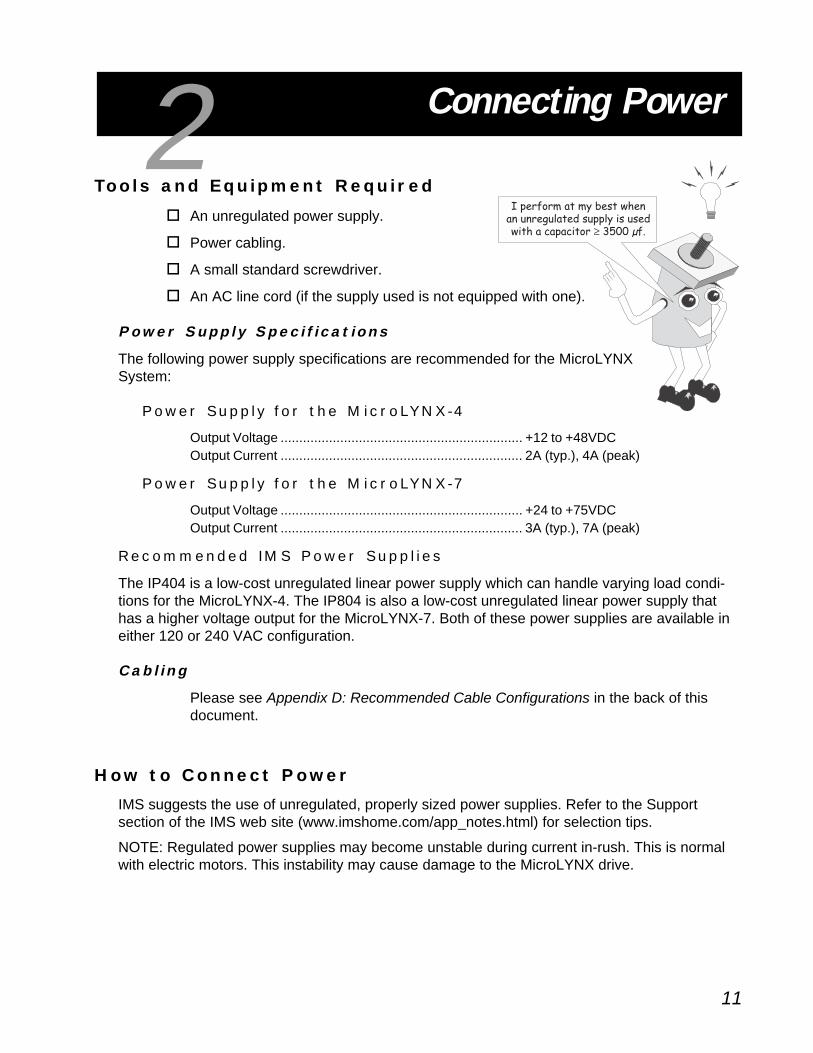
To o l s a n d E q u i p m e n t R e q u i r e d
! An unregulated power supply.
! Power cabling.
! A small standard screwdriver.
! An AC line cord (if the supply used is not equipped with one).
Powe r S upp l y S p e c i f i c a t i o n s
The following power supply specifications are recommended for the MicroLYNXSystem:
P o w e r S u p p l y f o r t h e M i c r o LY N X - 4
Output Voltage ................................................................. +12 to +48VDCOutput Current ................................................................. 2A (typ.), 4A (peak)
P o w e r S u p p l y f o r t h e M i c r o LY N X - 7
Output Voltage ................................................................. +24 to +75VDCOutput Current ................................................................. 3A (typ.), 7A (peak)
R e c o m m e n d e d I M S P o w e r S u p p l i e s
The IP404 is a low-cost unregulated linear power supply which can handle varying load condi-tions for the MicroLYNX-4. The IP804 is also a low-cost unregulated linear power supply thathas a higher voltage output for the MicroLYNX-7. Both of these power supplies are available ineither 120 or 240 VAC configuration.
C a b l i n g
Please see Appendix D: Recommended Cable Configurations in the back of thisdocument.
H o w t o C o n n e c t P o w e r
IMS suggests the use of unregulated, properly sized power supplies. Refer to the Supportsection of the IMS web site (www.imshome.com/app_notes.html) for selection tips.
NOTE: Regulated power supplies may become unstable during current in-rush. This is normalwith electric motors. This instability may cause damage to the MicroLYNX drive.
2

12
When connecting power to the MicroLYNX, ensure the following:
! At least 18 gauge wire is used for the MicroLYNX-4, 16 gauge for the MicroLYNX-7.
! +V and GND are not reversed.
! All connections are tight.
! Shielded twisted pair cabling with at least 1 twist per inch is used.
Figure 2.1: MicroLYNX Power Connection
Ensure the DC output of the power supply does not exceed themaximum input voltage.
All power supply wiring should be a shielded, twisted pair to reducesystem noise.
Shield to Earth/Chassis Ground
GR
OU
P 20 I/OC
OM
MU
NIC
ATION
S
MICROTM
PHASE APHASE APHASE BPHASE B
+VGND
12
3
J1J2
J3
IMS Power Supply
AC PowerConnection
WARNING! A characteristic of all motors is back EMF. Back EMF is a source of current that canpush the output of a power supply beyond the maximum operating voltage of the driver. Careshould be taken so that the back EMF does not exceed the maximum input voltage rating of theMicroLYNX.The maximum Specified Input Voltage of the MicroLYNX-4 and the MicroLYNX-7includes Motor Back EMF, Power Supply Ripple and High Line.

13
Connecting A Motor
To o l s a n d E q u i p m e n t R e q u i r e d
The following is required to connect a motor to yourMicroLYNX System:
! A stepping motor.
! Motor cabling (if the motor is not so equipped).
! A small standard screwdriver.
A S t e p p i n g Mo t o r
IMS recommends the following 1.8° Hybrid Stepping Motors for the MicroLYNXSystem. All IMS motors are CE marked. For more detailed information on thesemotors, please see the IMS motor catalog or the IMS web site atwww.imshome.com.
14 F r ame (M i c r o LYNX -4 )
Single Shaft Double ShaftM-1410-0.75S ................................................... ........................ M-1410-0.75D
17 F r ame (M i c r o LYNX -4 )
Single Shaft Double ShaftM-1713-1.5S................................................................................. M-1713-1.5DM-1715-1.5S................................................................................. M-1715-1.5DM-1719-1.5S................................................................................. M-1719-1.5D
23 F r ame (M i c r o LYNX -4/ - 7 )
Single Shaft Double ShaftM-2218-3.0S................................................................................. M-2218-3.0DM-2218-6.0S (MicroLYNX-7 only) ................................................ M-2218-6.0DM-2222-3.0S................................................................................. M-2222-3.0DM-2222-6.0S (MicroLYNX-7 only) ................................................ M-2222-6.0DM-2231-3.0S................................................................................. M-2231-3.0DM-2231-6.0S (MicroLYNX-7 only) ................................................ M-2231-6.0D
34 F r ame (M i c r o LYNX -7 )
Single Shaft Double ShaftM-3424-6.3S................................................................................. M-3424-6.3DM-3431-6.3S................................................................................. M-3431-6.3DM-3447-6.3S................................................................................. M-3447-6.3D
3

14
H o w t o C o n n e c t t h e M o t o r
There are basically three different lead configurations of stepping motors with a total of fivedifferent wiring configurations. These are:
8 L e ad Mo t o r
S e r i e s C o n f i g u r a t i o n
A series motor configuration would typically be used inapplications where a higher torque at low speeds isneeded. Because this configuration has the most induc-tance, the performance will start to degrade at higherspeeds. Use the unipolar current rating as the peakoutput current.
Figure 3.1: 8 Lead Motor, Series Connection
PHASE APHASE A
PHASE APHASE A
PHASE BPHASE B
PHASE BPHASE B
IMS I n s i d e - O u t S t e p p i n g Mo t o r s
The new Inside Out Stepper (IOS) motors were designed and patented by IMS to bring versatil-ity to small motors. These motors employ a unique multi-functional, hollow-shaft design. Bymounting a miniature ball screw to the front shaft face, the IOS motor can be converted to a ballscrew linear actuator. In addition to offering long life and high efficiency, ball screw linear actua-tors may be field retrofitted. There is no need to throw the motor away due to wear of the nut orscrew.
Frame IMS P/N17 Frame ................................................................................................. M3-1713-IOS23 Frame ................................................................................................. M3-2220-IOS34 Frame ................................................................................................. M3-3424-IOS42 Frame ................................................................................................. M3-4247-IOS
C a b l i n g
Shielded twisted pair cabling should be used to make the power supply connections to theMicroLYNX in the following gauges:
MicroLYNX-4 ................................................................ 18 gauge
MicroLYNX-7 ................................................................ 16 gauge

15
NOTE: Typically step motor current ratings are unipolar for 8 and 6 lead motors.
NOTE: If bipolar series current is given, multiply by 1.4 to determine the peak outputcurrent.
P a r a l l e l C o n f i g u r a t i o n
An 8 lead motor in a parallel configurationyields more torque at higher speeds than thesame motor wired in series. Multiply the perphase (or unipolar) current rating by 2.0, or thebipolar parallel current rating by 1.4 to deter-mine the peak output current.
6 L e ad Mo t o r
F u l l C o i l C o n f i g u r a t i o n
The full coil configuration on a 6 lead motor should be used in applications where highertorque at lower speeds is desired. This configuration is also referred to as full copper.Use the per phase (or unipolar) current rating as the peak output current.
PHASE APHASE A
PHASE APHASE A
PHASE BPHASE B
PHASE BPHASE B
Figure 3.2: 8 Lead Motor, Parallel Connection
PHASE APHASE A
PHASE APHASE ANO CONNECTION
PHASE BPHASE B
PHASE BPHASE BNO CONNECTION
Figure 3.3: 6 Lead Motor, Full Coil Connection

16
4 L e ad Mo t o r
4 lead motors are the least flexible but easiest to wire. Speed and torque will depend on windinginductance. In setting the driver output current, multiply the specified phase current by 1.4 todetermine the peak output current.
PHASE BPHASE BPHASE BPHASE B
NO CONNECTION
PHASE APHASE APHASE APHASE A
NO CONNECTION
Figure 3.4: 6 Lead Motor, Half Coil Connection
PHASE APHASE A
PHASE APHASE A
PHASE BPHASE B
PHASE BPHASE B
Figure 3.5: 4 Lead Motor Connections
H a l f C o i l C o n f i g u r a t i o n
As previously stated, the half coil configuration uses 50% of the motor phase windings.This gives lower inductance, hence, lower torque output at low speeds. As with theparallel connection of 8 lead motor, the torque output will be increased at higher speeds.This configuration is also referred to as half copper. In setting the driver output current,multiply the specified per phase (or unipolar) current rating by 1.4 to determine the peakoutput current.

17
Connecting Communications
One of the features that make the MicroLYNX a uniqueproduct is its dual COMM ports. This allows forsimultaneous use of both the RS-232 and the RS-485interface. This is especially useful in party mode whereseveral MicroLYNX nodes are networked in a system. Thissection will illustrate connecting your MicroLYNX to acommunications host, typically a PC, using a single MicroLYNX andeither the RS-232 interface or the RS-485 interface. For instructions onconnecting communications to multiple MicroLYNX Systems see theproduct manual.
To o l s a n d E q u i p m e n t R e q u i r e d
The following tools and equipment are required to connect communications toyour MicroLYNX System:
! IMS communications cable part # MX-CC100-000 or equivalent (if 10 pinheader version of the MicroLYNX is used).
! Communications cable (if 7 pin terminal version of the MicroLYNX is used).
! A free COM port on a PC.
Conne c t i n g C ommun i c a t i o n s
RS -232 I n t e r f a c e
The following diagram and table illustrate the connection of both the RS-232 and the RS-485interface to the MicroLYNX.
4
Figure 4.1: MicroLYNX with IMS Communications Cable

18
Figure 4.2: RS-232 Interface Connection
noitcennoCXNYLorciM232-SR
XNYLorciM CP
redaeHniP01 xineohPniP7 troPlaireSniP52 troPlaireSniP9
)XR(ataDevieceR3niP )XR(ataDevieceR1niP )XT(ataDtimsnarT2niP )XT(ataDtimsnarT3niP
)XT(ataDtimsnarT2niP )XT(ataDtimsnarT2niP )XR(ataDevieceR3niP )XR(ataDevieceR2niP
DNGC5niP DNGC6niP DNGC7niP DNGC5niP
Table 4.1: RS-232 Interface Connection
When using the RS-232 interface the MicroLYNX must be within 50 feet of the communicationshost.
RS -485 I n t e r f a c e
In a system consisting of a single MicroLYNX, the RS-485 interface should be used if theMicroLYNX will be more than 50 feet from the host PC. Since most PC’s do not come with anRS-485 interface preinstalled, you may need to install an RS-485 board in an open slot in yourPC, or purchase an RS-232 to RS-485 converter. If you are using a 4 wire RS-485 system, youcan also use the CV-3222 RS-232 to RS-422 converter sold by IMS.
MX-CC100-000

19
EXPANSIO
N M
OD
ULES
MICROTM
GR
OU
P 20 I/OC
OM
MU
NIC
ATION
S
13
4
PHASE A
PHASE A
PHASE B
PHASE B
V+
GNDPOWER SUPPLY
MicroLYNX (10 Pin Header)
RX+RX-TX-TX+
CGND
TX+TX-RX-RX+CGND
TXRX
CGND
Host PC
RS-232to
RS-485Converter
COMMUNICATIONS
Pin 1
Pin 2
Pin 9
Pin 10
Pin 1
Pin 1
RX-RX+TX-TX+CGND
CO
MM
UN
ICATIO
NS
MicroLYNX 4 (7 Pin Terminal)
Figure 4.3: RS-485 Interface Connection
metsySXNYLorciMelgniSecafretnI584-SR
584-SRot232-SRretrevnoC
XNYLorciM
langiS langiSniP01redaeH
niP7lanimreT
-XT -XR 7 3
+XT +XR 6 4
-XR -XT 8 5
+XR +XT 9 7
DNGC DNGC 5,01 6
Table 4.2: RS-485 Interface Connection
The following diagram and table illustrate the connection of the RS-485 interface.

20
Establishing CommunicationsTo o l s a n d E q u i p m e n t R e q u i r e d
The following tools and equipment are required to establish communications with your Micro-LYNX System:
! IMS Terminal software.
! A free COM port on a PC.
A Pe r s o na l C ompu t e r w i t h a F r e e COM Po r t
A PC running Windows 9x, NT4.0 SP6, 2000 SP1 or XP is required if the IMS Terminal softwarewill be used. However, any operating system that has support for an ASCII terminal can be usedto communicate with the MicroLYNX.
IMS Te rm i n a l S o f twa r e
The IMS Terminal software is provided to ease programmingthe MicroLYNX by combining a text editor and ASCIIterminal. This program is located on the IMS Product CDand can be installed quickly and easily.
The minimum system requirements are:
! A Pentium PC.! 10 MB hard drive space.! Windows 9x, NT 4.0, 2000 or XP.
I n s t a l l i n g t h e I M S Te r m i n a l S o f t w a r e
The IMS Terminal software is a programming/communications interface. Thissoftware was created by IMS to simplify programming and upgrading the MicroLYNXSystems. The IMS Terminal is also necessary to upgrade the software in yourMicroLYNX System. These updates will be posted to the IMS web site atwww.imshome.com as they are made available.
To install the IMS Terminal to your hard drive, insert the IMS Product CD into yourCD-ROM Drive. The CD should autostart to the IMS Main Index Page. If the CD doesnot start, click “Start > Run” and type “x:\IMS.exe” in the “Open” box and click OK.
NOTE: “x” is your CD ROM drive letter.
1) The IMS CD Main Index Page will be displayed.
2) Place your mouse pointer over the MicroLYNX Icon. The text message “LYNXFamily Product” will be displayed. This verifies you have selected the correctsoftware.
3) Click the MicroLYNX Icon to open the LYNX Product Page.
4) Place the mouse pointer over the menu and select IMS Terminal (Win9x) or(WinNT). Click your selection and the “Setup” dialog box will be displayed.
5) Click SETUP and follow the on-screen instructions.
5

21
Once IMS Terminal is installed the Communications Settings can be checked and/or set.
Detailed instructions for the IMS Terminal software can be located in the Software Referencesection of the MicroLYNX Operating Instructions.
1) To open IMS Terminal click Start>Programs>IMS Terminal>IMS Term. Thefollowing screen will be displayed.
2) On the Menu Bar: click <Edit> <Preferences> or right click in the Terminal
Window and click Preferences, or click the Preferences Button on the main
Tool Bar to display the Preferences Dialog Box.
3) Click the “Comm Settings” tab at the top of the dialog box.
4) Verify the Comm Port you are using.
5) Under “Device” near the bottom of the box verify that “LYNX” is selected. TheBAUD rate is already set to the MicroLYNX default. Do not change thissetting until you have established communications with the MicroLYNX.
6) The “Window Size” settings are strictly optional.
7) Click “APPLY” and “OK”. The settings will be automatically saved upon a normalshutdown.
8) Verify all connections and apply power to the system. The sign-on messagebelow should appear in the Terminal window.Program Copyright 2001-2003 by:
Intelligent Motion Systems, Inc.
Marlborough, CT 06447
VER = xxxxxx SER = Axxxxxx
U s i n g t h e I M S Te r m i n a l S o f t w a r e
The IMS Terminal software is an easy to setup and use interface for MicroLYNX programming.IMS Terminal is also required in order to upgrade the software in the MicroLYNX. The IMSTerminal program is fully covered in the MicroLYNX/LYNX Operating Instructions. Coverage inthis document is limited to what is required to communicate with the MicroLYNX, and to create,edit and download MicroLYNX programs.
Figure 5.1: IMS Terminal Main Window
PROGRAMEDITINGWINDOW
IMSTERMINALWINDOW
FUNCTIONKEYS

22
Con f i g u r i n g C ommun i c a t i o n S e t t i n g s
The communications settings are configured by means of the “Preferences Dialog”. This dialogis accessed through the “Edit > Preferences” menu item or by clicking the “Preferences” icon onthe toolbar. The preferences dialog gives the user the ability to set the format for text size, fontand color, as well as general communications settings. It is set by default to the optimum com-munications settings for the MicroLYNX. If you change the BAUD rate setting for the Micro-LYNX, power will have to be cycled for the change to take effect. Ensure that the IMS Terminalpreferences are adjusted for the new BAUD settings.
Down l o a d i n g a P r o g r am t o t h e M i c r o LYNX
There are two ways to download programs to the MicroLYNX:
1] Directly from the text editor window of the IMS Terminal.
2] From a text file located on a hard drive or removeable disk.
To download a program from the text editor window click the menu item “Transfer > Download”.The dialog box shown in the following figure will open. Select the “Source Type > Edit Window”option, click download. The program will transfer to the MicroLYNX.
Programs can be downloaded to the MicroLYNX from a text file by selecting “Source Type >File” on the dialog and typing in a drive location:\file name in the “File Name” box on the dialog,or browsing to the file location.
Figure 5.2: IMS Terminal Communications Setup Window

23
Figure 5.3: IMS Terminal Download Dialog
Figure 5.4: IMS Terminal Upload Dialog
Up l o a d i n g a P r o g r am F r om t h e M i c r o LYNX
Programs may also be uploaded from the MicroLYNX in two ways:
1] Directly to the text editor window of the IMS Terminal.
2] To a text file located on a hard drive or removeable disk.
To upload a program to the text editor window click the menu item “Transfer > Upload”. Thedialog box shown below will open. Select the “Destination Type > Edit Window” option, click“Upload. The program will transfer from the MicroLYNX.
Programs may be uploaded from the MicroLYNX to a text file by selecting “Destination Type >File” on the dialog and typing in a drive location:\file name in the “File Name” box on the dialog.

24
Controlling Motor Current
C u r r e n t C o n t r o l Va r i a b l e s
One of the unique and powerful features of the MicroLYNX is the precision current controlavailable through the instruction set. Unlike moststepper drives, which only offer the capability ofcontrolling run current and hold current, the Micro-LYNX also has the capability of setting the accelera-tion current. By setting the acceleration current to ahigher value, the system designer can deliver morepower to the system at the time when it is needed themost: when system inertia must be overcome. After-ward, when the motor has reached peak velocity, therun current may be set to a lower value, thus reducingmotor heating and improving system power efficiency.
All of these variables may be changed on-the-flyinside a MicroLYNX Program. The value range ofthese variables is a percentage (0 - 100%).PGM 200 'start program at address 200
LBL I_SET 'label program I_SET
MAC=40 'set acceleration current to40%
MRC=30 'set run current to 30%
MHC=10 'set holding current to 10%
ACCL=50000 'set acceleration to 50000 munits
MOVR 900000 'index relative 900000 munits
HOLD 2 'suspend program until motion completes
MAC=75 'set acceleration current to 75%
MRC=75 'set run current to 75%
MHC=50 'set holding current to 50%
VI=10000 'set initial velocity to 10000 munits/sec
ACCL=1000000 'set acceleration to 1000000 munits/sec2
MOVR -2000000 'index relative -2000000 munits
HOLD 2 'suspend program until motion completes
END
Figure 6.1: Motor Current Control Variables
6
Max Velocity(VM)
Initial Velocity (VI)Time
Acce
lerat
ion
Acce
lerat
ion
Deceleration
MAC=80
MAC=80MRC=35
HCDT=60MSDT=30
MHC=15(I = 80%)ACCL
(I = 80%)ACCL(I = 35%)RUN
(I Delay Time = 60ms)HOLD(Motor Settling
Delay Time = 30ms)
(I = 15%)HOLD

25
Setting The Motor Resolution
The output resolution of the drive section of the MicroLYNXis set by the MSEL variable. By viewing the table on the
right, you can see that thereare fourteen (14) resolutionsettings available with theMicroLYNX. These settingsmay be changed on-the-fly ineither immediate mode or ina program. The operation ofthis variable is illustrated inthe following exercise.
In this excercise write a shortprogram that will simply slewthe motor and cycle througha few of the binary microstepresolution settings. The lowerthe resolution, the higher thespeed of the motor.
7
S e t t i n g t h e M o t o r R e s o l u t i o nE x e r c i s e
Enter the following program into the text editor window of the IMS Terminal:MAC=75 'set acceleration current to 75%
MRC=75 'set run current to 75%
PGM 200 'start program at address 200
SLEW 8000 'slew the motor at 4000 munits/sec
HOLD 1 'suspend prog. until velocity change completes
MSEL=128 'set resolution to 128 msteps/step
DELAY 1000 'delay program 1 sec.
MSEL=64 'set resolution to 64 msteps/step
DELAY 1000 'delay program 1 sec.
MSEL=32 'set resolution to 32 msteps/step
DELAY 1000 'delay program 1 sec.
MSEL=16 'set resolution to 16 msteps/step
DELAY 1000 'delay program 1 sec.
MSEL=8 'set resolution to 8 msteps/step
DELAY 10000
END
PGM
Transfer the program to the MicroLYNX by clicking the menu item “Transfer > Download” andselecting “Edit window” as the source. Run the program by typing “EXEC 200” in the terminal.The motor should speed up as it cycles through the resolution setting.
sgnitteSnoituloseRpetsorciM
retemaraPLESM)petS/spetsorciM(
veR/spetsorciM
sgnitteSnoituloseRpetsorciMyraniB)rotoM°8.1(
2 004
4 008
8 006,1
61 002,3
23 004,6
46 008,21
821 006,52
652 002,15
sgnitteSnoituloseRpetsorciMlamiceD)rotoM°8.1(
5 000,1
01 000,2
52 000,5
05 000,01
521 000,52
052 000,05
Table 7.1: Microstep Resolution Settings

26
Using The Isolated Digital I/O
T h e I s o l a t e d D i g i t a l I / O D e f i n e d
The MicroLYNX comes standard with a set of six (6) +5 to+24VDC I/O lines which may be programmed individuallyas either general purpose or dedicated inputs or outputs,or collectively as a group. The isolated digital I/O may alsobe expanded to twenty-four (24) lines.
The I/O groups and lines are numbered in the followingfashion:
Group 20 = Lines 21 - 26 (Standard)
Group 30 = Lines 31 - 36 (Optional)
Group 40 = Lines 41 - 46 (Optional)
Group 50 = Lines 51 - 56 (Optional)
The isolated digital I/O may be defined as either activeHIGH or active LOW. When the I/O is configured asactive HIGH, the level is +5 to +24VDC and the statewill be read as a “1”. If the level is 0 VDC, then the state
will be read as “0”. Inversely, if configured as active LOW, then the state of the I/Owill be read as a “1” when the level is LOW, and a “0” when the level is HIGH. Theactive HIGH/LOW state is configured by the third parameter of the IOS variable,which is explained further on. The goal of this I/O configuration scheme is to maxi-mize compatibility between the MicroLYNX and standard sensors and switches.
Th e P i n C on f i g u r a t i o n o f t h e I s o l a t e d I /O
The following figure illustrates the pinout of I/O group 20:
Figure 8.1: Isolated I/O Pin Configuration
8
TM
GRO
UP 20 I/O
Pin 1: V Pull-UpPin 2: I/O Line 21Pin 3: I/O Line 22Pin 4: I/O Line 23Pin 5: I/O Line 24Pin 6: I/O Line 25Pin 7: I/O Line 26Pin 8: I/O Ground (Isolated)

27
Uses o f t h e I s o l a t e d D i g i t a l I /O
The isolated I/O may be utilized to receive input from external devices such as sensors, switchesor PLC outputs. When configured as outputs, devices such as relays, solenoids, LED’s and PLCinputs may be controlled from the MicroLYNX. Depending on the device connected, the input oroutput may be pulled-up to either the internal +5VDC supply or an external +5 to +24VDCsupply, or the I/O lines may be pulled-down to ground.
These features, combined with the programmability and robust construction of the MicroLYNXI/O make possible many uses for the I/O in your application.
Setting Pull -up Voltage for the Isolated Digital I/O
The isolated I/O lines may be pulled-up two ways. Depending on your I/O setup and devices used,it will be necessary for you to set the switches or supply an external pull-up voltage.
1] The internal +5VDC, Pull-Up* supply.
2] An external +5 to +24VDC supply.
I n t e r n a l +5VDC
When using the internal +5VDC supply, the I/O line is pulled-up through a 7.5kW resistor. Topull the I/O line up to the internal supply, the switches for the I/O lines being pulled-up must beplaced in the ON position.
*NOTE: This is not to be used as a +5VDC output, only as a pull-up voltage if the user does notwish to supply an external voltage.
Exte rna l +5 to +24VDC Supp ly
If a higher voltage is needed, an external supply may be connected. The pull-up switches will beON, and the V+ output of the supply connected to pin 1 (V PULLUP) and the supply return (GND)would be connected to pin 8 (I/O GROUND) of the MicroLYNX I/O connector.
INPUTS
OUTPUTS
SensorsSwitches
PLC Outputs
RelaysSolenoids
LED’sPLC Inputs
MicroLYNXSystem
Figure 8.2: Isolated I/O Applications

28
T h e I n p u t O u t p u t S e t u p Va r i a b l e( I O S )
Before continuing any further with the “I/O Setup” it is impor-tant to have a solid understanding of the I/O setup variable:IOS. The MicroLYNX I/O scheme is a powerful tool formachine and process control. Because of this power, a levelof complexity in setup and use is found that doesn’t exist incontrollers with a less capable I/O set.
Each I/O line may be individually programmed to any one of8 dedicated input functions, 7 dedicated output functions, oras general purpose inputs or outputs. The I/O may be ad-dressed individually or as a group. The active state of the lineor group may also be set. All of these possible functions areaccomplished with the IOS variable
The IOS variable has three parameters when used to config-ure the isolated digital I/O. These are:
1] I/O Line Type: Specifies general purpose or dedicated function for a line orgroup of I/O.
2] I/O Line Function: Either an input or an output.
3] Active State: Specifies whether the line will be active HIGH or active LOW.
The default configuration of I/O group 20 is: 0,0,1. This means that by default each line in group20 is configured to be a General Purpose (0), Input (0), which is active when HIGH (1). Thefollowing figure and exercises illustrate possible configurations of the IOS.
I OS E x e r c i s e # 1 : S e t t i n g a Ded i c a t e d Ou t p u t
IOS = , , XXX X XTo configure an entire I/O Group enter the
Group # (20, 30, 40 or 50) here!
To configure an individual I/O Line enter the Line # (21-26, 31-36, 41-46,
or 51-56) here!
Enter I/O Line Type # Here
0 = General Purpose9 = Start Input10 = Stop Input11 = Pause Input12 = Home Input13 = Limit Plus Input14 = Limit Minus Input15 = Reset Drive Input
16 = Jog Plus Input17 = Jog Minus Input18 = Moving Output19 = Indexing in Progress Output20 = Velocity Change21 = Program Running Output22 = Stall Output23 = Error Output24 = Program Paused
Define Line or GroupAs Input or Output
0 = Input1 = Output
Set the state of the Line or Group
0 = Active Low1 = Active High
Figure 8.3: The IOS Variable Settings

29
Connect an LED to I/O line 21 that will illuminate when the motor is moving.
Connect the LED to the I/O line as shown and use a 9V batteryas a power source. Enter the following in the terminal:
IOS 21 = 18,1,0
The “18” tells the MicroLYNX that I/O line 21 isto be a dedicated Moving output. The secondparameter MUST be set to “1” defining the lineas an output. The third parameter is set to “0”
making the line active LOW.
Now test the configuration byturning the power on andentering the following into theterminal:
SLEW 200000
While the motor is moving the LED should be illuminated.Pressing the Escape (Esc) key will stop the motion and theLED will turn off.
I O S E x e r c i s e # 2 A : S e t t i n g a D e d i c a t e d I n p u t A c t i v e L o w
In this example connect a switch that will soft stop the motor when pressed. Leave theconnections and settings from the previous example. When the switch is used to stop themotion the LED will turn off, verifying that the step-clock pulses are no longer being sent tothe motor driver.
Connect the switch as shown. Set the pull-up switch for I/O line 22 in the ON position,pulling the line up to the internal +5 volts.
Enter the following into the terminal:
IOS 22 = 10,0,0
The “10” instructs the MicroLYNX to set I/O line 22 to be adedicated Soft Stop input. Since it is an input, the secondparameter is set to 0. The third parameter is set 0, oractive LOW, as the switch will pull the input down toground.
Now, we test the configuration by entering “SLEW 200000”into the terminal, the LED should turn off. Press theswitch. The motor should stop and the LED illuminate.
CURRENTLIMITINGRESISTOR
9V Battery
I/O LINE 21
LED
+
I/OGND
Figure 8.4: IOS Exercise #1
I/O LINE 22
I/O GROUND
PUSH BUTTONSWITCH
Figure 8.5: IOS Exercise #2A

30
IOS Exercise # 2B: Setting a Dedicated Input Active High
In this example use the same type of switch and LED configura-tion as in the previous example, except instead of connectingthe switch between I/O 22 and I/O GND, connect the switchbetween I/O 22 and V PULL. As before, use the switch to SoftStop the motor.
Connect the switch as shown. Since the I/O line will be pulledup to +5VDC using the push button switch to activate it, thepull-up switch for line 22 will be in the OFF position.
Enter the following into the terminal:
IOS 22 = 10,0,1
As before, the line is a Soft Stop (10) input (0), only this time itis set it to be active HIGH (1) instead of LOW. Now the line willbe active when +5V is realized. Slew the motor to test the setup. When the switch is depressedthe motor will stop and the LED will turn off.
Leave the LED and switch connected for the next two examples.
I OS Exerc ise # 3: Sett ing a Genera l Purpose Output
In this example use the LED connected to I/O line 21 and write a small program that will causethe LED to illuminate following a short move, wait for two seconds, turn the LED off, then re-peat.
Enter the following program into the text editor window of the IMS Terminal software. It isn’t neces-sary to type in the comments, which are preceded by the apostophe (‘). These are there to explaineach line of code. In actual program development they are a troubleshooting aid.IOS 21 = 0,1,0 'set I/O line 21 = gen. purpose out, active low
PGM 200 'start program at address 200
LBL IO_TEST 'name program IO_TEST
MOVR 51200 'index to relative position 51200
HOLD 2 'hold program execution until motion done
IO 21 = 1 'set I/O line 21 active
DELAY 2000 'wait 2 seconds
IO 21 = 0 'set I/O line 21 inactive
BR IO_TEST 'loop to beginning of program
END
PGM
When completed, download the program to yourMicroLYNX by clicking the menu item “Transfer >Download” on the IMS Terminal menu bar. Select“Edit Window” as the source type on the downloaddialog, click download. The program will transfer toyour MicroLYNX.
I/O LINE 22
PUSH BUTTONSWITCH
V PULL
Figure 8.6: IOS Exercise #2B

31
Test your program by entering “EXEC IO_TEST” into the terminal window. The motorshould move 51200 microsteps (1 revolution for a 1.8° stepper motor with the MicroLYNX atthe default microstep resolution of 256), the LED will illuminate for 2 seconds, turn off, and theprocess will repeat itself until the escape key is pressed.
At this point you will want to clear and restore your MicroLYNX, this is done by entering thefollowing in the terminal window:
CP 1,1DVF ,,1IP
I OS Exe r c i se # 4 : Se t t i ng a Genera l Purpose I npu t
In this next example build on the last one and do something a little more complex. In this ex-ample the program will run as in the previous example, except a subroutine will be added thatwill change the delay from 2 seconds to 0.5 seconds and move the motor 25,700 microsteps inthe opposite direction, repeating this until the switch is released.
Enter the following program into the text editor window of the IMS Terminal software:IOS 21 = 0,1,0 'set I/O line 21 = gen. purpose out, active low
IOS 22 = 0,0,1 'set I/O line 22 = gen. purpose in, active high
PGM 200 'start program at address 200
LBL IO_TEST2 'name program IO_TEST2
CALL ON_IN, IO 22=1 'call sub ON_IN when I/O 22 is active
MOVR 51200 'index to relative position 51200
HOLD 2 'suspend program until motion completes
IO 21 = 1 'set I/O line 21 active
DELAY 2000 'wait 2 seconds
IO 21 = 0 'set I/O line 21 inactive
BR IO_TEST2 'loop to beginning of program
LBL ON_IN 'declare sub ON_IN
MOVR -25700 'index 25,700 in neg. direction
HOLD 2 'suspend program until motion completes
IO 21 = 1 'set I/O line 21 active
DELAY 500 'wait 0.5 seconds
IO 21 = 0 'set I/O line 21 inactive
BR ON_IN, IO 22=1 'loop to ON_IN while I/O line 22 is active
RET 'return from subroutine
END
PGM
Download the program to the MicroLYNX. Test its operation by entering “EXEC 200” or“IO_TEST2” in the terminal window. The motor and LED should operate as it did in the previousexample, however, when you depress and hold the switch, the motor will move half a revolution inthe opposite direction and only delay 0.5 seconds between moves. This should repeat as long asthe switch is held. When the switch is released, the MicroLYNX should return to the main pro-gram. The main program will be executed until either the switch is depressed again or the escapekey is pressed.

32
T h e I O Va r i a b l e
After configuring the I/O by means of the IOS variable,you need to be able to do two things with the I/O.
1] Write to an output, or group of outputs,thus setting or changing its (their) state.
2] Read the states of either inputs or outputs.This information can be used to eitherdisplay those states to our terminal, or toset up conditions for branches and subroutinecalls within a program.
In the example program in IOS Exercise #4 both of thesemethods were used in the IO variable. First it was used towrite to the state of I/O line 21, which was set up as ageneral purpose output. Second, it was used to read thestate of I/O line 22, which was set up as a general pur-pose input to call up a subroutine within your program.
You can also use this command to write or read the state of an entire I/O group.
Read/Wr i t e a S i n g l e I /O L i n e
To read the state of a single input or output, the following would be typed into the terminal:
PRINT IO 21
The response from this would be 1 or 0, depending on the state of the line.
The state of an input or output in a program can be used to direct events within a MicroLYNXprogram by either calling up a subroutine using the “CALL” instruction, or conditionally branch-ing to another program address using the “BR” instruction. This would be done as follows:
CALL MYSUB, IO 22=1
This would call up a subroutine labled “MYSUB” when I/O line 21 is active.
BR 200, IO 22=0
This would branch to address 200 when I/O line 22 is inactive.
Writing to an output is accomplished by entering the following into a terminal or program:
IO 21=1
IO 21=0
This would change the state of I/O line 21.
Read/Wr i t e a n I /O G r o up
When using the IO variable to read the state of a group of inputs/outputs or write to a group ofoutputs, you would first want to configure the entire I/O group to be general purpose inputs oroutputs using the IOS variable. In this case the response or input won’t be a logic state of 1 or0, but rather the decimal equivalent (0 to 63) of the 6 bit binary number represented by theentire group.
When addressing the I/O as a group, the LSB (Least Significant Bit) will be line 1 of the group(e.g. 21, 31, 41, 51). The MSB (Most Significant Bit) will be line 6 (e.g. 26, 36, 46, 56).

33
This first exercise will illustrate setting the I/O as a group using outputs. In the second exercise ashort program is used to set up the I/O group as a binary counter.
To perform these exercises you will need six (6) LED’s with current limiting resistors and a 9 voltbattery or equivalent +5 to +24VDC power supply. It is possible to perform these exerciseswithout connecting anything to the I/O, however, the LED’s clearly show how the I/O is beingutilized as a group.
I O Va r i a b l e E x e r c i s e #1
Setup your I/O group in accordance with the figure 8.6. The pull-up switches on the MicroLYNX should be ON.
The table on the left shows the bit weight of each I/O line in thegroup. It also illustrates the LED’s and their state that shouldappear when entering the IO variables in this exercise.
Configure the IOS variable such that group 20 is all generalpurpose outputs, active low or:
IOS 20 = 0,1,0
Enter the following in the terminal:
IO 20 = 35
As shown in the table, I/O lines 26, 22 and 21 should be illumi-nated and 25, 24 and 23 should be off.
Enter this next:
IO 20 = 7
Now I/O 21, 22 and 23 should be illuminated.
IO 20 = 49
I/O 26, 25, and 21 are illuminated.
In each case you can calculate the decimal equivalent by addingthe weights of the bits that are set in the I/O group.
+9V
Battery
V PULL
I/O 21
I/O 22
I/O 23
I/O 24
I/O 25
I/O 26
I/O GND
Figure 8.6: IO Variable Exercise Setup
1 1 10 0 0
BINARY STATE OF I/O GROUP 20IO 20 = 35
I/O 21LSB
I/O 26MSB I/O 22I/O 23I/O 24I/O 25
32 2 116 8 4
BIT WEIGHT DISTRIBUTION TABLEFOR GROUP 20 I/O
I/O 21LSB
I/O 26MSB I/O 22I/O 23I/O 24I/O 25
0 1 10 0 1
BINARY STATE OF I/O GROUP 20IO 20 = 7
I/O 21LSB
I/O 26MSB I/O 22I/O 23I/O 24I/O 25
1 0 11 0 0
BINARY STATE OF I/O GROUP 20IO 20 = 49
I/O 21LSB
I/O 26MSB I/O 22I/O 23I/O 24I/O 25
Table 8.1: Binary State of Outputs

34
Reading the state of inputs will work the very same way. In a real-world example you may notbe using LED’s, but rather outputing to, or receiving input from, PLC inputs or outputs for pro-cess control applications. In this case, in your MicroLYNX program, you may want to call upvarious subroutines when the I/O group is at a certain state. This gives you the power ofprogramming up to 63 events in your process controlled by the standard I/O group on theMicroLYNX.
I O Va r i a b l e E x e r c i s e #2
In this exercise use a short program that will use I/O group 20 as a binary counter. The programwill display the decimal equivalent of the binary count on the screen. It will also move the motora short distance and wait 0.25 seconds in between counts.
Type the following into the text editor window and save. Download to MicroLYNX.IOS 20 = 0,1,0 'set I/O group 20 = gen. purp. outputs, active low
IO 20 = 0 'set the state of I/O group 20 to 0
PGM 200 'start program at address 200
LBL IO_CNT 'name the program "IO_CNT"
VI=100000 'set the init. velocity = 100,000 munits/sec.
IO 20=IO 20+1 'add 1 to the value of I/O group 20
MOVR 10000 'move relative 10000 munits
HOLD 2 'suspend program until motion completes
DELAY 250 'wait 0.25 seconds
PRINT "\rThe decimal state of I/O Group 20 is: " IO 20;
BR IO_CNT, IO 20=<63 'loop to IO_CNT while I/O 20 is lss that 63
PRINT "\nALL DONE!" 'line feed to next line print ALL DONE
END
PGM
EXEC IO_CNT to run the program. The LED’s will cycle and the number will count up on theterminal screen.
Set t i ng t he D i g i t a l F i l t e r i ng f o r t he I/O ( IOF )
User-definable digital filtering makes the MicroLYNX well suited for noisy industrial environ-ments. The IOF variable allows the user to software select filter settings ranging from 215 Hz to27.5 kHz.
The IOF variable has 1 parameter with a range of 1 to 7 as shown in the following table.
O/IdetalosIesopruPlareneGehtrofsgnitteSretliFFOI)7-0=>mun<(>mun<=FOI
gnitteSretliFffotuC
ycneuqerFesluPelbatceteDmuminiM
htdiW
0 zHk5.72 sdnocesorcim81
1 zHk7.31 sdnocesorcim63
2 zHk98.6 sdnocesorcim37
3 zHk44.3 sdnocesorcim541
4 zHk27.1 sdnocesorcim092
5 zH068 sdnocesorcim185
6 zH034 sdnocesillim261.1
)tluafed(7 zH512 sdnocesillim323.2
Table 8.2: IOF Settings

35
Expanding The MicroLYNX
M i c r o LY N X E x p a n s i o n M o d u l e s
Add i t i o n a l I s o l a t e d D i g i t a l I /O
The Isolated Digital I/O can be expanded to 3 groups (30 - 50) for a total of 24 programmable I/O lines.These Modules may be installed in any available slot. The group number will be determined by the Micro-LYNX slot into which they are plugged: slot 1 will be group 30, slot 2 will be group 40, and slot 3 will begroup 50. These Expansion Modules are configured and used in the same manner as the Standard I/O onthe MicroLYNX. The IMS Part # is MX-DI100-000 (8 Pin Terminal) or MX-DI200-000 (10 Pin Header).
H i g h - S p e e d D i f f e r e n t i a l I /O Modu l e
If your system requires closed loop motion control and/or ratio functions, such as following or electronicgearing or the ability to sequentially control a second axis, up to two High-Speed Differential I/O Modulescan be installed in slots 2 and 3 of the MicroLYNX, giving three channels of high-speed differential (orsingle) I/O a piece. The IMS Part # is MX-DD100-000 (8 Pin Terminal) or MX-DD200-000 (10 Pin Header).
Ana l o g I n p u t/Jo y s t i c k Modu l e
The Analog Input/Joystick Interface Module features two 12 bit, 0 to +5 volt input channels which can beused to monitor devices such as temperature and pressure sensors. It can also be used to control an axiswith a joystick. It features two voltage outputs: a 5 volt joystick reference, and a precision 4.096 voltcalibration reference. This device can be installed in any available MicroLYNX slot. The IMS Part # is MX-AJ100-000 (8 Pin Terminal) or MX-AJ200-000 (10 Pin Header).
I s o l a t e d C ommun i c a t i o n s Modu l e
The Isolated Communications Module allows a second, fully independent Communication Port when usinga CAN Based MicroLYNX Control System. This Module comes in a choice of RS-232 or RS-485. The IMSPart# is MX-CM102-000 (RS-232 w/8 Pin Terminal), MX-CM202-000 (RS-232 w/10 Pin Header), MX-CM104-000 (RS-485 w/8 Pin Terminal) or MX-CM204-000 (RS-485 w/10 Pin Header).
Ana l o g Ou t p u t Modu l e
The Analog Output Module provides two 0 to +5 VDC Output Channels (four if two Modules are used).This Module adds the capability to control AC Variable Frequency Drives, Servo Drives and Brush-TypeDC Drives. The IMS Part# is MX-DA100-000 (8 Pin Terminal) or MX-DA200-000 (10 Pin Header).
12 Channe l I s o l a t e d D i g i t a l I /O Modu l e
The 12 Channel Isolated Digital I/O Module provides twelve +5 to +24 VDC Isolated I/O Channels. Thiscoupled with a the Six Channel Isolated I/O Module will yield the maximum 24 Isolated I/O Channels in theMicroLYNX and leave an open slot for an Expansion Module of a different type. The IMS Part# is MX-DI400-000 (16 Pin Header) or MX-DI401-000 (16 Pin and Receptacle).
C h o o s i n g t h e E x p a n s i o n M o d u l e s f o r Yo u r A p p l i c a t i o n
A powerful feature of the MicroLYNX is versatility offered by its wide range of configurations available via theexpansion modules. The expansion modules listed above may be used singly or in combination to customizeyour MicroLYNX System to the specific requirements of your application. The table on the following pagelists a collection of possible application requirements and their suggested MicroLYNX configurations.
9

36
#niP
noitpOrotcennoC
xineohPnoitisoP8 redaeHniP01
1tolS 2tolS 3tolS 1tolS 2tolS 3tolS
1 V pullup V pullup V pullup 13O/I 14O/I 15O/I
2 13O/I 14O/I 15O/I 23O/I 24O/I 25O/I
3 23O/I 24O/I 25O/I V pullup V pullup V pullup
4 33O/I 34O/I 35O/I 33O/I 34O/I 35O/I
5 43O/I 44O/I 45O/I .C.N .C.N .C.N
6 53O/I 54O/I 55O/I 43O/I 44O/I 45O/I
7 63O/I 64O/I 65O/I .C.N .C.N .C.N
8 DNGO/I DNGO/I DNGO/I 53O/I 54O/I 55O/I
9 DNGO/I DNGO/I DNGO/I
01 63O/I 64O/I 65O/I
Table 9.2: Isolated Digital I/O Group and Line Locations
E x p a n d i n g t h e I s o l a t e d D i g i t a l I / O
The Isolated Digital I/O can be expanded to 24 lines. Expansion to this level would require theuse of all three slots. The I/O groups are slot dependent. The slots will yield the followinggroups as numbered:
Slot 1............................................. Group 30
Slot 2............................................. Group 40
Slot 3............................................. Group 50
Table 9.1: MicroLYNX Expansion Module Configurations
* The MicroLYNX is capable of handling up to 24 I/O signals. If you should opt touse a 12 Channel I/O Module, you can only use one Isolated Digital I/O Module.
egasUtolSnoisnapxEXNYLorciMnoisnapxE
eludoM 1tolS 2tolS 3tolS mumixaMdewollA
0/IlatigiDdetalosI seY seY seY *3
deepShgiHO/IlaitnereffiD oN seY seY 2
golanAkcitsyoJ/tupnI seY seY seY 1
detalosInoitacinummoC oN seY oN 1
tuptuOgolanA seY seY seY 2
O/IlennahC21 seY seY oN *1

37
I n s t a l l i n g T h e I s o l a t e d D i g i t a l I /O Modu l e
To install the Isolated Digital I/O Expansion Module in your MicroLYNX, follow the steps below.
To Install the Module:
1) Remove the two retaining screws (A) from the cover.2) Remove the blank panel (1, 2 or 3) from the slot you want to use.3) Carefully press the Expansion Module (B) into place by plugging the 28 pin
connector into the desired receptacle (C, D or E) and snapping it into placeunder the retaining clips (F).
4) Reinstall the MicroLYNX cover.5) Affix the labels supplied with the Module as shown.
Figure 9.1: Installing the Isolated Digital I/O Module
ACDE
FA
RemoveDesiredPanel
ISOLATED DIGITAL I/0
SLOT# [1] [2] [3]
TERMINAL BLOCK
1. V PULL-UP2. I/O CHANNEL 13. I/O CHANNEL 24. I/O CHANNEL 35. I/O CHANNEL 46. I/O CHANNEL 57. I/O CHANNEL 68. I/O GROUND
• ISOLATED DIGITAL I/0
ISOLATED DIGITAL I/0
SLOT# [1] [2] [3]
TERMINAL BLOCK
1. V PULL-UP
2. I.O CHANNEL 1
3. I/O CHANNEL 2
4. I/O CHANNEL 3
5. I/O CHANNEL 4
6. I/O CHANNEL 5
7. I/O CHANNEL 6
8. I/O GROUND
• IS
OLA
TED
DIG
ITAL
I/0
B
Tightening TorqueSpecification For [A]:
4 to 5 lb-in(0.45 to 0.56 N-m)
Us ing the I so la ted D ig i ta l I /O
The isolated digital expansion I/O operates in the same manner as the standard isolated I/O. Theonly differences are the location of the pull-up switches and the method of supplying an externalpull-up voltage.
The pull-up switches are located on the bottom of the expansion board and operate in the samefashion as the standard I/O set pull-ups. Configuring and using these switches is detailed inSection 8 of this document.
Figure 9.2: The Isolated Digital I/O Module, Bottom View
ON1 2 3 4 5 6
IO1
IO2
IO3
IO4
IO5
IO6
IO1
IO2
IO3
IO4
IO5
IO6
VPULL
INTELLIGENT MOTION SYSTEMS, INCMICROLYNX ISOLATED I/O
GNDIO
2.184(55.47)
0.970(24.64)
PULL-UP SWITCH

38
T h e H i g h - S p e e d D i f f e r e n t i a l I / O M o d u l e
The MicroLYNX can accept up to two High-Speed Differential I/O Modules installed in expan-sion slot numbers 2 and 3. The High-Speed Differential I/O Module expands the capabilities ofthe MicroLYNX to include application features such as:
1] Closed Loop Motion Control (Encoder Feedback).2] Electronic Gearing (Ratio Functions).3] Secondary Clock Output.4] General Purpose High-Speed I/O.
The pinout by slot location and connector style is given in Table 9.4.
The high-speed differential I/O is non-isolated, meaning the ground is not common with theisolated I/O ground.
Figure 9.3: Powering Multiple Isolated Digital I/O Modules
+V GND
I/O Ground
V Pull-up Pin 1
Pin 1Pin 8
Group 20Standard I/O
Gro
up 3
0Is
olat
ed I/
OG
roup
40
Isol
ated
I/O
+5 to +24 VDCPower Supply
MICROTM
Pin 1
Another key difference is the method by which an externalpull-up voltage is supplied to the I/O. While the I/O Ground iscommon to each installed Isolated Digital I/O Module (boththe Differential I/O Module and the Analog Input Modulehave separate, non-isolated grounds), V-PULLUP is NOTcommon. This allows you to power each I/O group indepen-dently if you choose.
The expansion isolated digital I/O is configured and controlledby the IOS variable and the IO instructions in the samemanner as the standard I/O set. The only difference is in howthe lines and groups are addressed. See Section 8 for in-structions on using the isolated I/O.
If digital filtering is used (IOF variable) it must beconfigured for each group separately.

39
lacirtcelEdraoBnoisnapxEO/IlaitnereffiDdeepS-hgiHscitsiretcarahC
noitacificepS
ycneuqerFkcolC.xaM zHM5
gniretliFtupnIlatigiD zHM5otzHk93
rewoPredocnE tuptuOCDV5+
)denibmoCstuptuOllA(timiLtnerruC Am051
noitisoPtolS 3ro2
seludoMelbasU#.xaM 2
Table 9.3: High Speed DifferentialElectrical Characteristics
#niP
noitpOrotcennoC
xineohPnoitisoP8 redaeHniP01
2tolS 3tolS 2tolS 3tolS
1 )-(71O/I )-(81O/I .C.N .C.N
2 DNG DNG CDV5+ CDV5+
3 CDV5+ CDV5+ DNG DNG
4 )-(41O/I )-(61O/I )-(41O/I )-(61O/I
5 )+(31O/I )+(51O/I )-(31O/I )-(51O/I
6 )+(41O/I )+(61O/I )+(31O/I )+(51O/I
7 )+(71O/I )+(81O/I )-(41O/I )-(61O/I
8 )-(31O/I )-(51O/I )+(41O/I )+(61O/I
9 )-(71O/I )-(81O/I
01 )+(71O/I )+(81O/I
Table 9.4: High-Speed Differential I/O Pinout
I n s t a l l i n g t h e H i g h - S p e e d D i f f e r e n t i a l I /O Modu l e
To install the High-Speed Differential I/O Module into your MicroLYNX, follow the steps below.
To Install the Module:
1) Remove the two retaining screws (A) from the cover.2) Remove the blank panel (2 or 3) from the desired slot.3) Carefully press the Expansion Module (B) into place by plugging the 28 pin
connector into the desired receptacle (D or E) and snapping it into place under theretaining clips (F).
4) Reinstall the MicroLYNX cover.5) Affix the labels supplied with the Module as shown.
Th e F o u r C l o c k s E x p l a i n e d
A
B
DE
FA
RemoveDesiredPanel
HIGH-SPEED DIFF I/0
SLOT# [2] [3]
TERMINAL BLOCK
1. CHANNEL C –2. GROUND3. +5VDC OUTPUT4. CHANNEL B –5. CHANNEL A +6. CHANNEL B +7. CHANNEL C +8. CHANNEL A –
• HIGH-SPEED DIFF I/0
HIGH-SPEED DIFF I/0
SLOT# [2] [3]
TERMINAL BLOCK
1. CHANNEL C –
2. GROUND
3. +5VDC OUTPUT
4. CHANNEL B –
5. CHANNEL A +
6. CHANNEL B +
7. CHANNEL C +
8. CHANNEL A –
• H
IGH
-SPEE
D D
IFF
I/0
Figure 9.4: Installing the High-Speed Differential I/O Module
Tightening TorqueSpecification For [A]:
4 to 5 lb-in(0.45 to 0.56 N-m)

40
#kcolC riaPeniLO/I noitisoPtolS retnuoC noitcnuF
1 21&11 enoN 1RTCpetSsedivorptI.kcolcnoitomdetarenegyllanretninasikcolcsihTtonsikcolcsihT.noitcesrevirdehtotlortnocnoitceriDdnakcolC
.rotcennoclanretxeynanoelbaliava
2 41&31 2tolS 2RTCsihttluafedyB.tuptuorotupninasaderugifnocebyamkcolcsihT
saderugifnocebnactI.tupnIerutardauQasaderugifnocsikcolc.1KLCotderaegyllacinortceletuptuokcolcyradnocesa
3 61&51 3tolS 3RTCsihttluafedyB.tuptuorotupninasaderugifnocebyamkcolcsihT
saderugifnocebnactI.tupnIerutardauQasaderugifnocsikcolc.1KLCotderaegyllacinortceletuptuokcolcyraitreta
471 2tolS enoN
.tuptuOrotupnIdeepShgiHasaderugifnocebyamkcolcsihTnasititluafedyB.kcolcecnereferzHM1asiti,tuptuOnasA
.lennahcxednIredocnEehttcetedotdesuebnactidna,tupnI
81 3tolS enoN .tuptuOrotupnIdeepShgiHasaderugifnocebyamkcolcsihT.kcolcecnereferzHM01asiti,tuptuOnasA
Table 9.5: The Four Clocks and Their Default Line Placement
When using a clock pair as Step and Direction, the lower number orthe “A” clock of the pair will always be the Direction. The highernumber or the “B” clock of the pair will always be the Step Clock.
The MicroLYNX has four clock pairs that are used by the high-speed I/O. One clock pair (11 and12) is fixed as an output and is used internally to provide step clock and direction pulses to thedriver section of the MicroLYNX. The step clock output increments CTR1 (Counter 1). The userhas no physical access to this clock but it may be read from or written to by software instructionsin either program or immediate mode. The following table explains the clocks as well as theirdefault I/O line pair placement.
C l o c k Ty p e s De f i n e d
There are three basic types of clocks that may be configured forthe MicroLYNX, they are:
1] Quadrature2] Step/Direction3] Up/Down
These clock functions are illustrated in Figure 9.5.
Q u a d r a t u r e
The quadrature clock function is the most commonly used input.This is the default setting for each high-speed I/O channel except11 & 12. This clock function will typically be used for closed loopcontrol (encoder feedback) or for following applications.
S t e p / D i r e c t i o n
The step/direction clock function would typically be used in anapplication where a secondary or tertiary clock output is requiredto sequentially control an additional axis.
NOTE: On clocks configured for Step/Direction, the LOW numberof the I/O Line pair will be Direction and the HIGH number of the I/O Line pair will be StepClock.
U p / D o w n
The up/down clock type would typically be used as an output function where a secondary axis isbeing driven by a stepper or servo drive with dual-clock direction control circuitry.
Con f i g u r i n g t h e D i f f e r en t i a l I /O - T he I OS Va r i a b l e
Up/Down
CW
CCW
Quadrature
Channel A
Channel B
Step Clock
Step Clock/Direction
Direction
Figure 9.5: Clock Functions

41
The high-speed differential I/O is configured by means of the IOS variable and is used in the thesame fashion in which the isolated I/O is configured. The main difference lies in that there arethree additional parameters which need to be set in configuring the triggering, clock type andratio mode setting.
It is important to note that the high-speed differential I/O lines may be used for the same inputor output functions as the isolated digital I/O where the higher speed capabilities of the differen-tial I/O is required. However, for purposes of this example we will only illustrate the clock func-tions associated with the high-speed differential I/O. The figure below illustrates the IOS vari-able settings for the high speed differential I/O.
Con f i g u r i n g t h e H i g h - S p e e d I /O t o a Non - C l o c k F u n c t i o n
Configuring the high-speed I/O to clock functions will becovered in depth in the following subsections onconfiguring encoder and ratio functions. Here we willbriefly discuss using the high-speed I/O as a generalpurpose or dedicated I/O function.
Care must be taken when configuring the high-speed I/Oto a general purpose or dedicated function as the outputcurrent sink is 150mA for the entire I/O group 10.
The IOS variable will be configured for the high-speed I/Oin the same fashion as it is set for the isolated I/O.
For detailed usage example see Section 12, SampleApplications: Registration.
Figure 9.6: IOS Settings for the High-Speed Differential I/O
IOS = , , , , , X XXX X XX X
Enter the Channel # (13-18) here!
Enter I/O Line Type # Here
1 = Clock 1A2 = 3 = 4 = 5 = 6 = 7 = 8 =
Clock 1BClock 2AClock 2BClock 3AClock 3BClock 4AClock 4B
Define Line or GroupAs Input or Output
0 = Input1 = Output
Define the Clock Type
0 = Not A Clock 1 = Quadrature 2 = Step/Direction 3 = Up/Down
Set the state of the Line or Group
0 = Active Low1 = Active High
Set the Ratio Mode 0 = No Ratio 1 =Ratio
Set the Triggering0 = Level1 = Edge
NOTE: The Clock #’s arefixed to theirassociated I/Ochannel and cannot be changed! Theyare entered forsake of consistencyonly!

42
Conne c t i n g a n d C on f i g u r i n g a n E n c o d e r
The high-speed differential I/O module may be used for closed loop motion control by receivingquadrature input from a differential or single ended encoder.
High-Speed I/O channels 13 and 14 are configured by default for this function, so insert theexpansion module into expansion slot #2.
Connect your encoder as shown in the following figure and table.
MICROTM
12
3
or
MicroLYNX
Phase A
Phase B
PowerSupply
V+GND
Phase B
Phase A
Group 2
0 I/
OCom
munications
Connection using 10 Pin Header
1--------
3--------
5--------
7--------
9--------
2---
4---
6---
8---
10---
NC+5 VDCGNDChannel B -Channel A -Channel A +Channel B -Channel B +Index -Index +
DifferentialEncoder
SteppingMotor
Connection Illustrating8 Pin Terminal
12345678
Index -Ground+5 VDCChannel B -Channel A +Channel B +Index +Channel A -
Figure 9.7: Differential Encoder Connection
2#tolSnoisnapxE-snoitcennoCredocnE
langiSredocnE XNYLorciM
laitnereffiD elgniS lennahCO/I xinoehPnoitisoP8 *redaeHniP01
+AlennahC AlennahC +31 5 6
-AlennahC -31 8 5
+BlennahC BlennahC +41 6 8
-BlennahC -41 4 7ro4
+xednI xednI +71 7 01
-xednI -71 1 9
CDV5+ CDV5+ 3 2
DNG DNG 2 3
siredocneruoyfisuhT.noitarugifnocnipdrakcaPttelweHehtwollofredocnelaitnereffidSMI:ETONelbacnobbirNIDelamefhtiwelbacnobbir"deriwhguorhtthgiarts"rotcudnoc01aSMIroPHybderutcafunam
redaeHniP01(draobnoisnapxeehtdnaredocnelaitnereffidehtneewtebyltceriddetcennocebnacsrotcennoc.noitacifidomgniriwtuohtiw)noisreV
Table 9.6: Expansion Slot #2 Encoder Connections

43
Te s t i n g t h e E n c o d e r S e t u p
Now that the encoder is connected, you can test thesetup and verify its operation by typing the following intoyour terminal:MUNIT=51200 ‘set munits to correspond with
‘MSEL=256
EUNIT=2000 ‘set the encoder units variable‘EUNIT to the number = 4 x encoder‘resolution, ie 500 line encoder x‘4 = 2000, 200 line encoder x 4 =‘800 etc.
STLF=200 ‘Set the stall factor variable to‘10% of EUNIT (10% of a revolution)
EE=1 ‘Enable encoder functions
POS=0 ‘set position counter to 0
CTR2=0 ‘set counter 2 to 0
SAVE ‘save the aforementioned settings.
Test the encoder setup by entering the following into your terminal:MOVR 10 ‘the motor moves 10 revolutions
PRINT POS ‘read the POS variable, it should say “10.000”
PRINT CTR2 ‘read CTR2, it should read 10 X EUNIT, or 20000
I n t r o d u c i n g T h e E U N I T ( E n c o d e r U N I T S ) Va r i a b l e
During open loop operation, the MicroLYNX takes the number of clock pulses registered on CTR1, scalesthat number using the MUNIT variable and then writes the result to the position variable POS.
For closed loop operation, where the encoder functions are enabled (EE=1), the MicroLYNX takes thenumber of clock pulses registered on CTR2, scales them by the EUNIT variable and stores them to thePOS counter.
The EUNIT variable must be scaled to the same factor as the MUNIT variable. For example, if you werescaling your system to operate in degrees, the MUNIT/EUNITrelationship would be expressed thus:
MUNIT=51200/360
EUNIT=2000/360
(This assumes MSEL=256 and a 500 line encoder.)
With this configuration if you performed the followingabsolute move:
MOVA 270
The axis would turn 270°. Thus when you enter:PRINT POS
The terminal will display “270.00”.
The program that follows will illustrate encoder feedbackby making a series of moves while displaying both theraw counts from CTR2 and the scaled POS value.

44
Enter the program below in the text editor window.'******PARAMETERS*******
MUNIT=51200 'motor units = 1/256 resolution
EUNIT=2000 '500 line encoder quad input
EE=1 'enable encoder functions
STLF=200 'stall factor 10% of 1 rev.
STLDE=1 'enable stall detection
STLDM=0 'stop motion if stall is detected
MAC=75 'accel. current to 75%
MRC=50 'run current to 50%
MHC=25 'hold current to 25%
'******PROGRAM********
PGM 200
CTR2=0
POS=0
MOVR 1
HOLD 2
DELAY 250
PRINT "\rEncoder Count= ", CTR2, " Position Count= ", POS,"\e[K";
MOVR 10
HOLD 2
DELAY 250
PRINT "\rEncoder Count= ", CTR2, " Position Count= ", POS,"\e[K";
MOVR -11
HOLD 2
DELAY 250
PRINT "\rEncoder Count= ", CTR2, " Position Count= ", POS,"\e[K";
BR 200
END
PGM
Execute the program by entering “EXEC 200” into the terminal.
F o l l ow i n g a n E x t e r n a l C l o c k ( E l e c t r o n i c G e a r i n g )
The High-Speed Differential I/O Module allows you toconfigure the MicroLYNX’s primary axis to follow anexternal clock input. The hardware connection (Figure 9.8)is almost identical to that shown for closed loop control. Inthis instance instead of using a quadrature clock input forposition monitoring and maintenance the encoder input willbe used to control the primary axis.
Using this type of application introduces the HAE (HalfAxis Enable) flag and the HAS (Half Axis Scaling) variable.In half axis mode the master clock is taken from the CLK2,CLK3 or CLK4 (I/O channels 13 & 14, 15 & 16, or 17 &18), which have the IOS variable configured as inputs, aclock type and ratio mode enabled. The primary axis willmove as a ratio of this clock based upon the factor enteredin the HAS variable.

45
H A E - H a l f A x i s E n a b l e / D i s a b l e F l a g
This flag (1) enables and (0) disables half axis scaling mode. The default condition is (0) dis-abled. The HAE flag must be enabled for this mode to function.
H A S - H a l f A x i s S c a l i n g Va r i a b l e
The half axis scaling variable is the factor by which the Follower Input: Primary Axis ratio isscaled. The range of the factor is >-1 to <1. For example, a setting of HAS=0.5 will output 1pulse on the primary axis for every 2 pulses input to the follower input or a 2:1 ratio, HAS=0.2will be 5:1, HAS=0.999 will be 0.999:1 and so on. The default HAS value is 0.000, thus somefactor must be entered to make this function.
C o n f i g u r i n g t h e I / O f o r H a l f A x i s M o d e
The parameter setup to make this configuration follows. This assumes a High-Speed DifferentialI/O Expansion Module installed in slot 2. If your module is installed in slot 3, use I/O channels15 and 16 (IOS 15=5,0,1,0,1,1 and IOS 16=6,0,1,0,1,1) instead. The raw count of clock pulseswill register to CTR3. I/O channels 17 and 18 can be used for this also, only there is no registra-tion of clock pulses:IOS 13=3,0,1,0,1,1 ‘I/O 13 quad. input, ratio mode
IOS 14=4,0,1,0,1,1 ‘I/O 14 quad. input, ratio mode
HAE=1 ‘Enable half-axis scaling mode
HAS=.5 ‘Half-axis scaling variable to 0.5 (1 output‘pulse on the pri. axis for 2 input pulses)
With this configuration, one (1) step clock pulse will output to the primary axis for every two (2)input clock pulses.
By reading the value of CTR2 and CTR1 you can see the ratio of the pulses.
Try different HAS variable, motor resolution and MUNIT settings to see how the primary axis iseffected by different settings.
Connection Showing 10 Pin Header
Pin 1Pin 2Pin 3Pin 4Pin 5Pin 6Pin 7Pin 8Pin 9
Pin 10
NC+5 VDCGNDChannel B –Channel A –Channel A +Channel B –Channel B +Index -Index +
or
GNDV+
PHASE APHASE A
PHASE BPHASE B
TM
GRO
UP20
I/OCO
MM
UNICA TIONS
MicroLYNX
POWERSUPPLY
12
3
DifferentialEncoder
SteppingMotor
Connection Showing 8 PositionPhoenix Terminal
Parameter SetupIOS 13=3,0,1,0,1,1IOS 14=4,0,1,0,1,1HAE=1HAS=0.5
IDX-GND+5 VDCChannel B-Channel A+Channel B+IDX +Channel A-
12345678
Figure 9.8: Differential I/O Connections for Following an External Input

46
T h e A n a l o g I n p u t / J o y s t i c k M o d u l e
The Analog Input/Joystick Module adds two 0to +5 volt analog input channels to the Micro-LYNX System. Both channels may be usedfor data aquisition, or either channel may beused to directly control motion. This offers theuser the capability of receiving input from avariety of analog sources such as tempera-ture or pressure sensors, and then controllingevents based upon those inputs.
The user-selected Joystick channel can beprogrammed to set the range, zero, dead-band and sensitivity.
Each channel uses a 12 bit D/A converterfor better resolution as well as a fixed singlepole analog filter with a cutoff frequency of658 Hz to reduce the electrical noise thatmay be present in industrial environments.
The Analog Input/Joystick Module can beinstalled in any free slot, however only one(1) module can be used per MicroLYNX.
snoitacificepSeludoMkcitsyoJ/tupnIgolanA
noitacificepS
egnaRegatloVtupnIgolanA stlov5+ot0
noituloseR stiB21
tesffO BSL3±
rorrEytiraeniLlargetnI BSL2±
rorrEytiraeniLlaitnereffiD BSL4/3±
stupnItaegatloVmumixaMetulosbA stlov42±
egatloVecnerefeRkcitsyoJ stlov5+
ecnerefeRnoitarbilaCnoisicerPegatloV
stlov690.4+%2.0±
ecnareloTegatloVecnerefeRnoitarbilaC %2±
.qerFffotuCretliFtupnIgolanA zH856
noitisoPtolS 3ro2,1
elbasU#mumixaM 1
Table 9.7: Analog Input Module Specifications
#niP
noitpOrotcennoC
xineohPnoitisoP8 redaeHniP01
1 )ecnerefeRkcitsyoJ(V5+ )ecnerefeRkcitsyoJ(V5+
2 1NIA DNG
3 DNG 1NIA
4 )ecnerefeRkcitsyoJ(V5+ )ecnerefeRkcitsyoJ(V5+
5 2NIA DNG
6 DNG 2NIA
7 )ecnerefeR.bilaC(V690.4 )ecnerefeR.bilaC(V690.4
8 DNG DNG
9 DNG
01 .C.N
Table 9.8: Analog Input/Joystick Module Pin Configuration
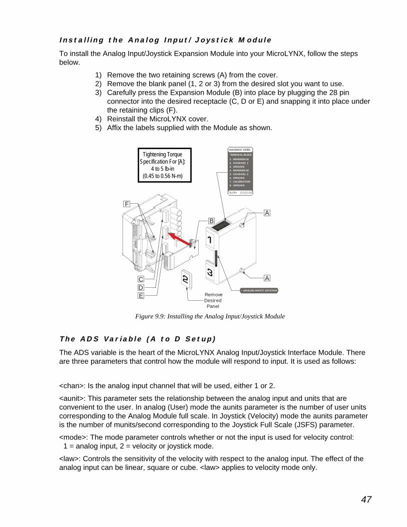
47
ACDE
FA
RemoveDesiredPanel
ANALOG INPUT/JOYSTICK
SLOT# [1] [2] [3]
TERMINAL BLOCK
1. REFERENCE2. CHANNEL 13. GROUND4. REFERENCE5. CHANNEL 26. GROUND7. CALIBRATION8. GROUND
• ANALOG INPUT/JOYSTICK
ANALOG INPUT/JOYSTICK
SLOT# [1] [2] [3]
TERMINAL BLOCK
1. REFERENCE
2. CHANNEL 1
3. GROUND
4. REFERENCE
5. CHANNEL 2
6. GROUND
7. CALIBRATION
8. GROUND
• AN
ALO
G IN
PU
T/JO
YSTI
CK
B
I n s t a l l i n g t h e Ana l o g I n p u t/Jo y s t i c k Modu l e
To install the Analog Input/Joystick Expansion Module into your MicroLYNX, follow the stepsbelow.
1) Remove the two retaining screws (A) from the cover.2) Remove the blank panel (1, 2 or 3) from the desired slot you want to use.3) Carefully press the Expansion Module (B) into place by plugging the 28 pin
connector into the desired receptacle (C, D or E) and snapping it into place underthe retaining clips (F).
4) Reinstall the MicroLYNX cover.5) Affix the labels supplied with the Module as shown.
Figure 9.9: Installing the Analog Input/Joystick Module
Tightening TorqueSpecification For [A]:
4 to 5 lb-in(0.45 to 0.56 N-m)
Th e ADS Va r i a b l e ( A t o D S e t u p )
The ADS variable is the heart of the MicroLYNX Analog Input/Joystick Interface Module. Thereare three parameters that control how the module will respond to input. It is used as follows:
ADS <chan>=<aunit>,<mode>,<law>
<chan>: Is the analog input channel that will be used, either 1 or 2.
<aunit>: This parameter sets the relationship between the analog input and units that areconvenient to the user. In analog (User) mode the aunits parameter is the number of user unitscorresponding to the Analog Module full scale. In Joystick (Velocity) mode the aunits parameteris the number of munits/second corresponding to the Joystick Full Scale (JSFS) parameter.
<mode>: The mode parameter controls whether or not the input is used for velocity control: 1 = analog input, 2 = velocity or joystick mode.
<law>: Controls the sensitivity of the velocity with respect to the analog input. The effect of theanalog input can be linear, square or cube. <law> applies to velocity mode only.

48
Here are two examples that illustrate the ADS variable:
E x a m p l e 1
A pressure transducer is connected to input 1. The transducer output is 10 psi/volt. Vref repre-sents the voltage at the Input to the Analog Joystick Module corresponding to full scale. Vref asmeasured at pin 1 on the Analog Joystick Module is 5.05 volts. Thus aunits for channel 1 is 10psi/volt x 5.05 volts or 50.5. The value returned by an analog read of Channel 1 will be in psi.Note that the full scale output of the transducer does not have to equal the Analog Module fullscale. This setup would be expressed thus:
ADS 1=50.5, 1
E x a m p l e 2
A 1.8 degree (per full step) motor connected to a lead screw with a lead of 0.1 inches/rev. Thestep motor drive is set for 32 usteps per full step. A joystick is connected to channel 1. To pro-gram speed and motion in inches set munits to (32 pulses/1.8 degrees) x (360 degrees/1 rev ) x (1rev/.1 inches). If a maximum speed of 3 inches/second is desired while in Joystick operation setaunits for channel 1 to 3. For linear Joystick operation the setup command is ADS 1 = 3,2,1.
P r og r am E x amp l e s
There are three program exercises we will use to illustrate the use of the Analog Input/JoystickModule. In each case a 1kW potentiometer is used to emulate a sensor for analog input mode,and a joystick for velocity mode.
Use the connection configuration shown in the figure above. A joystick or a sensor would beconnected the same way.
E x e r c i s e 1 : Ve l o c i t y ( J o y s t i c k ) M o d e
Here the potentiometer is emulating a joystick. Enter and execute the following program. Whenthe voltage on AIN 1 is roughly 100mV either side of 2.5 volts it will be in the deadband range ofthe joystick. When less than 2.4 volts, the axis will accelerate in the minus (-) direction. Whenmore than 2.6 volts, it will accelerate in the positive (+) direction. The velocity will increase asthe voltage decreases from 2.4 to 0, or increases from 2.6 to 5.0. This can be watched with amultimeter. In this exercise both the axis velocity and position will display to the terminal screen.
GNDV+
PHASE APHASE A
PHASE BPHASE B
TM
GRO
UP 20 I/OCO
MM
UNICATIONS
MicroLYNX
POWERSUPPLY
12
3EXPAN
SION
BOAR
DS
+5V Reference
AIN 1
Ground1 kΩ
Potentiometer
Motor, Power andCommunicationsConnections not
shown.
Figure 9.10: Analog Input Module Exercise Connection

49
'****Parameters****MSEL=256MRC=100MAC=100MUNIT=51200JSDB=100 ‘Joystick deadband =100 aunitsVM =10000 ‘max velocity 10,000 munits/secADS 1=1000,2,1 ‘chan. 1,aunits=1000, joystick, linear lawJSE = 1 ‘enable joystick functions'****Program****PGM 1PRINT "\e[2J" LBL RUN PRINT "\e[1;1HInput Channel = " , AIN PRINT "Axis Velocity = " , VEL PRINT "Axis Position = " , POS BR RUNENDPGM
E x e r c i s e 2 : S e n s o r I n p u t I
Assume the potentiometer is a pressure transducer. Use it to display a pressure value.ADS 1=50.5,1 ‘set ADS to aunit=50.5,analog input modePGM 200LBL PRNTPSI ‘name program “PRNTPSI”PRINT "\e[2J" ‘ansi esc. to clear displayPRINT "Pressure = ", AIN 1 , " PSI"BR PRNTPSI ‘loop to program beginningENDPGM
E x e r c i s e 3 : S e n s o r I n p u t I I
Once again assume the potentiometer is a sensor. In this exercise the program will call asubroutine based upon the voltage at AIN 1 and position the axis at an absolute position. Thebest analog to this exercise might be a flow control application.'****Parameters****MUNIT=51200 ‘munits=51200MAC=75 ‘acceleration current to 75%MRC=50 ‘run current to 50%ADS 1=5,1 ‘aunits 5, analog input modeVAR LIMIT=0 ‘declare user var “LIMIT”'****Program****PGM 200LBL AINTST ‘name program “AINTST”LIMIT = AIN 1 ‘set user var “LIMIT” = AIN 1CALL ATEST, LIMIT>3.5 ‘call ATEST if LIMIT is greater than 3.5 aunitsCALL BTEST, LIMIT<3.5 ‘call BTEST if LIMIT is less than 3.5 aunitsBR 200 ‘loop to beginning of programEND'****Subroutines****LBL ATEST ‘declare subroutine “ATEST”VM=20 ‘max. velocity = 20 munits/sec.MOVA 10 ‘index to abs. pos. 10HOLD 2 ‘suspend prog. until motion completesRET ‘return from subroutineLBL BTEST ‘declare subroutine “BTEST”VM=5 ‘max velocity = 5 munits/sec.MOVA 22 ‘index to abs. pos. 22HOLD 2 ‘suspend prog. until motion completesRET ‘return from subroutine

50
Table 9.9: RS-232 Pinout
T h e I s o l a t e d C o m m u n i c a t i o n s M o d u l e
The Isolated Communications Module adds either RS-232 or RS-485 to the CAN based Micro-LYNX motion control system. This second communication port is fully independent and opticallyisolated from I/O and input power ground. It may be used to communicate to an operator inter-face or for system diagnostics while the system is in use.
Table 9.10: RS-485 Pinout
A
FA
RemoveSlot 2Panel
ISOLATED COMMUNICATION
SLOT# [2]
TERMINAL BLOCK
1. NC2. NC3. NC4. RX -5. RX +6. TX -7. COMM GROUND8. TX +
• ISOLATED COMMUNICATION
ISOLATED COMMUNICATION
SLOT# [1] [2] [3]
TERMINAL BLOCK
1. NC2. NC3. NC4. RX -5. RX +6. TX -7. COMM GROUND
8. TX +
• ISO
LATE
D C
OM
MU
NIC
ATIO
N
B
D
I n s t a l l i n g t h e I s o l a t e d C ommun i c a t i o n s Modu l e
To Install the Isolated Communications Module into your MicroLYNX, follow thesteps below.
1) Remove the two retaining screws (A) from the cover.2) Remove the blank panel from the #2 slot.3) Carefully press the Expansion Module (B) into place by plugging the 28 pin
connector into the #2 receptacle and snapping it into place under the retainingclips (F).
4) Reinstall the MicroLYNX cover.5) Affix the labels supplied with the Module as shown.
Figure 9.11: Installing the Isolated Communications Module
eludoMnoisnapxE232-SR
#niP
noitpOrotcennoC
noitisoP8xineohP
redaeHniP01
1 DNGC .C.N
2 XR232-SR XT232-SR
3 XT232-SR XR232-SR
4 C.N .C.N
5 .C.N DNGC
6 .C.N .C.N
7 .C.N .C.N
8 .C.N .C.N
9 .C.N
01 .C.N
eludoMnoisnapxE584-SR
#niP
noitpOrotcennoC
noitisoP8xineohP
redaeHniP01
1 .C.N .C.N
2 .C.N .C.N
3 .C.N .C.N
4 -XR584-SR .C.N
5 +XR584-SR DNGC
6 -XT584-SR +XR584-SR
7 DNGC -XR584-SR
8 +XT584-SR -XT584-SR
9 +XT584-SR
01 DNGC
Tightening TorqueSpecification For [A]:
4 to 5 lb-in(0.45 to 0.56 N-m)

51
T h e A n a l o g O u t p u t M o d u l e
The Analog Output Module gives the MicroLYNXthe ability to control drives that require an analogcontrol signal such as variable frequency drives,servos and brush-type DC motor drives. It addstwo 0 to +5 volt output channels to thefunctionality of the MicroLYNX. Each channelfeatures 12 bit resolution and may beprogrammed to one of three operational modes:voltage, velocity or position. Each of thesemodes may be set to a 2.5V centerpoint for plusor minus operation.
In many cases, this module may save theexpense and complexity of using a PLC byenabling MicroLYNX to handle applications such asIndexing Conveyor, Material Handling and Feed RateOverride.
#niP noitpOrotcennoC
niP8kcolBlanimreT redaeHniP01
1 dnuorG dnuorG
2 )3tols(3HC,)2-1stols(1HC dnuorG
3 dnuorG )3tols(3HC,)2-1stols(1HC
4 dnuorG dnuorG
5 )3tols(4HC,)2-1stols(2HC dnuorG
6 dnuorG )3tols(4HC,)2-1stols(2HC
7 CN CN
8 CN dnuorG
9 CN
01 CN
Table 9.11: Analog Output Module Pinout
ACDE
FA
RemoveDesiredPanel
ANALOG INPUT/JOYSTICK
SLOT# [1] [2] [3]
TERMINAL BLOCK
1. REFERENCE2. CHANNEL 13. GROUND4. REFERENCE5. CHANNEL 26. GROUND7. CALIBRATION8. GROUND
• ANALOG INPUT/JOYSTICK
ANALOG INPUT/JOYSTICK
SLOT# [1] [2] [3]
TERMINAL BLOCK
1. REFERENCE
2. CHANNEL 1
3. GROUND
4. REFERENCE
5. CHANNEL 2
6. GROUND
7. CALIBRATION
8. GROUND
• AN
ALO
G IN
PU
T/JO
YSTI
CK
B
I n s t a l l i n g t h e Ana l o g Ou t p u t Modu l e
To Install the Analog Output Module into your MicroLYNX, follow the steps below.
1) Remove the two retaining screws (A) from the cover.2) Remove the blank panel (1, 2 or 3) from the desired slot you want to use.3) Carefully press the Expansion Module (B) into place by plugging the 28 pin
connector into the desired receptacle (C, D or E) and snapping it into placeunder the retaining clips (F).
4) Reinstall the MicroLYNX cover.5) Affix the labels supplied with the Module as shown.
Figure 9.12: Installing the Analog Output Module
Tightening TorqueSpecification For [A]:
4 to 5 lb-in(0.45 to 0.56 N-m)

52
Ana l o g Ou t p u t C ommands
The Analog output module adds 3 new commands to the MicroLYNX code and is available in FirmwareVersion1.528 or higher.
The commands are AOUT, VAE and DAS.
MNEMONIC DESCRIPTION OPCODEAOUT <chan> = <value>*AUNIT If DAS = 1 or 2 Analog OUT 7Ch (124)
AOUT <chan> = Velocity*AUNIT*MUNIT Analog OUT 7Ch (124)AOUT <chan> = Position*AUNIT*MUNIT
Converts using this formula if DAS = 3,4,5 or 6
Outputs scaled <value> to the D to A Board. (Converts scaled <value> from D to A) DAS = 1 or 2or
Converts using this formula if DAS = 3: Velocity*AUNIT*MUNIT = 0 to 4095 countsConverts using this formula if DAS = 4: Velocity*AUNIT*MUNIT = -2048 to +2047 countsConverts using this formula if DAS = 5: Position*AUNIT*MUNIT = 0 to 4095 countsConverts using this formula if DAS = 6: Position*AUNIT*MUNIT = -2048 to +2047 counts
MNEMONIC DESCRIPTION OPCODEVAE = 0 or 1 Velocity or position C2h (194)
0 for DAS 1 & 2 to Analog Enable1 for DAS 3, 4, 5 or 6
Enables Velocity or Position to be sent to the digital to analog channel that has a DAS type of 3 to 6.
MNEMONIC DESCRIPTION OPCODEDAS chan = AUNIT,type Digital to Analog B4h (180)
Output Setup
type = 1 to 6 (all types produce 0 to 5 volts)1 = Volts, absolute <value>2 = Volts, plus or minus centered around 2.5 volts3 = Velocity, absolute Velocity4 = Velocity, plus or minus centered around 2.5 volts5 = Position, absolute Position6 = Position, plus or minus centered around 2.5 volts
For setting up Digital to Analog channels:
chan = 1,2 when in slot 2chan = 3,4 when in slot 3value = 0 to 4095 when AUNIT = 1value = 32 bit IEEE floating point when AUNIT not 0 or not 1AUNIT = 1 or 32 bit IEEE floating point. NOT ZERO4095 / USER_UNITS; Absolute types (DAS=1, 3, 5)4095 / (USER_UNITS * 2); plus or minus types (DAS = 2, 4, 6)

53
Abso l u t e Ty p e E x amp l e s ( F o r 0 t o 5 Vo l t O u t p u t )
Result: With DAS=1 and AUNIT = 4095/5 and VAE = 0.AOUT <chan> = <value>AOUT <chan> = 1 volt when <value> = 1; AOUT = 2.75 volts when <value> = 2.75.
Result: With DAS = 3 and AUNIT = 4095/5*51200 and MSEL=256 and MUNIT = 51200 and VAE = 1.AOUT <chan> = 1 volt when Velocity = 1; AOUT = 2.75 volts when Velocity = 2.75.
Result: With DAS = 5 and AUNIT = 4095/5*51200 and MSEL=256 and MUNIT = 51200 and VAE = 1.AOUT <chan> = 1 volt when Position = 1; AOUT = 2.75 volts when Position = 2.75.
P l u s o r M i n u s Ty p e E x amp l e s
Set an analog value (as if controlling a speed of 0 to 10000 steps/sec in a separate drive) and controldirection:
AOUT <chan> = <value>Result: With DAS = 2 and AUNIT = 4095/20000 and VAE = 0.AOUT <chan> = 2.5 volts when <value> = 0;AOUT <chan> = 5 volts when <value> = +10000;AOUT <chan> = 0 volts when <value> = -10000.
Result: With DAS = 4 and AUNIT = 4095/20000 and MSEL = 2 and MUNIT = 1 and VAE = 1.AOUT <chan> = 2.5 volt when Velocity = 0;AOUT <chan> = 5 volts when Velocity = 10000;AOUT <chan> = 0 volts when Velocity = -10000
Result: With DAS = 6 and AUNIT = 4095/20000 and MSEL = 2 and MUNIT = 1 and VAE = 1.AOUT <chan> = 2.5 volt when Position = 0;AOUT <chan> = 5 volts when Position = 10000AOUT <chan> = 0 volts when Position = -10000
T h e 1 2 C h a n n e l I s o l a t e d D i g i t a l I / O M o d u l eThe 12 Channel Isolated Digital I/O Module adds an additional twelve +5 to 24 VDC isolated I/O channels.All of the I/O channels can be individually programmed as either inputs or outputs, or as dedicated (limit,home, etc.) or general purpose.
When used as inputs, these I/O channels have seven programmable digital filter settings ranging from 215Hz to 27.5 kHz. As outputs, each channel can sink up to 350 mA. The I/O is isolated from the powersupply ground.
A 7.5kOhm switch selectable pull-up resistor is provided for each I/O channel. The twelve I/O channelsmay be pulled up to either the internal +5 VDC supply or an external voltage provided by the user. Protec-tion circuitry includes over temperature, short circuit and inductive current clamp.
sredaeHniP61)H(esoriH/)S(cetmaS
s#niP noitcnuF s#niP noitcnuF
)S(1 )H(51 ApU-lluPV )S(9 )H(7 BpU-lluPV
)S(2 )H(61 A1lennahCO/I )S(01 )H(8 B1lennahCO/I
)S(3 )H(31 A2lennahCO/I )S(11 )H(5 B2lennahCO/I
)S(4 )H(41 A3lennahCO/I )S(21 )H(6 B3lennahCO/I
)S(5 )H(11 A4lennahCO/I )S(31 )H(3 B4lennahCO/I
)S(6 )H(21 A5lennahCO/I )S(41 )H(4 B5lennahCO/I
)S(7 )H(9 A6lennahCO/I )S(51 )H(1 B6lennahCO/I
)S(8 )H(01 AdnuorGO/I )S(61 )H(2 BdnuorGO/I
Table 9.12: 12 Channel Isolated I/O Module Pinout

54
Pu l l - u p Sw i t c h e s
The Isolated Digital I/O Module is equipped with Pull-up switches which are located on thebottom of the Module. The switches operate in the same manner as the standard Isolated I/O.See Section 10 “Configuring the Isolated Digital I/O” in the MIcroLYNX Section of the Micro-LYNX/LYNX Operating Instructions for details.
Figure 9.14: 12 Channel I/O Module Pull-up Switches
ON1
23
45
6
ON1
23
45
6
Channel X 1-6 Channel Y 1-6
A
B
CD
FA
RemoveDesiredPanel
• 12 CHANNEL I/O
• 1
2 C
HAN
NEL
I/O
12 CHANNEL I/O
SLOT# [1] [2]
SAMTEC CONNECTOR
1. V-PULLA
2. I/O CH1A
3. I/O CH2A
4. I/O CH3A
5. I/O CH4A
6. I/O CH5A
7. I/O CH6A
8. I/O GND A
9. V-PULLB
10. I/O CH1B
11. I/O CH2B
12. I/O CH3B
13. I/O CH4B
14. I/O CH5B
15. I/O CH6B
16. I/O GNDB
12 CHANNEL I/O
SLOT# [1]
SAMTEC CONNECTOR
1. V PULLA2. I/O CH1A
3. I/O CH2A4. I/O CH3A
5. I/O CH4A
6. I/O CH5A7. I/O CH6A
8. I/O GNDA
9. V PULLB10. I/O CH1B
11. I/O CH2B
12. I/O CH3B
13. I/O CH4B
14.I/O CH5A
15. I/O CH6B
8. I/O GNDB
To Install the 12 Channel I/O Module into your MicroLYNX, follow the steps below.1) Remove the two retaining screws (A) from the cover.2) Remove the blank panel (1 or 2) from the desired slot you want to use.3) Carefully press the Expansion Module (B) into place by plugging the 28 pin
connector into the desired receptacle (C or D) and snapping it into place underthe retaining clips (F).
4) Reinstall the MicroLYNX cover.5) Affix the labels supplied with the Module as shown.
I n s t a l l i n g t h e 12 Channe l I /O Modu l e
Figure 9.13: Installing the 12 Channel Isolated I/O Module
Tightening TorqueSpecification For [A]:
4 to 5 lb-in(0.45 to 0.56 N-m)
I /O Con f i g u r a t i o n
Inputs and Outputs as well as digital filtering are configured in the same manner as the Stan-dard I/O (Group 20).
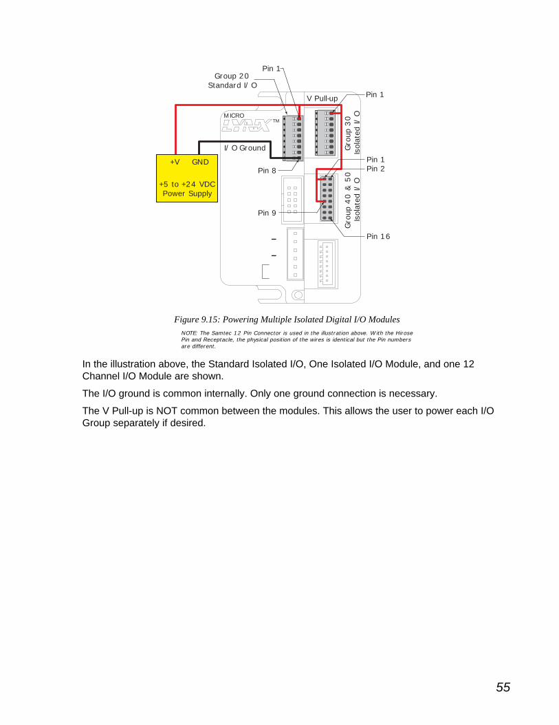
55
Figure 9.15: Powering Multiple Isolated Digital I/O Modules
In the illustration above, the Standard Isolated I/O, One Isolated I/O Module, and one 12Channel I/O Module are shown.
The I/O ground is common internally. Only one ground connection is necessary.
The V Pull-up is NOT common between the modules. This allows the user to power each I/OGroup separately if desired.
+V GND
I/O Ground
V Pull-up Pin 1
Pin 8
Group 20Standard I/O
Gro
up 3
0Is
olat
ed I/
OG
roup
40 &
50
Isol
ated
I/O+5 to +24 VDC
Power Supply
MICROTM
Pin 1
Pin 1
Pin 16
Pin 9
Pin 2
NOTE: The Samtec 12 Pin Connector is used in the illustration above. With the HirosePin and Receptacle, the physical position of the wires is identical but the Pin numbersare different.

56
MicroLYNX Software Components 10Mic r o LYNX So f twa r e C omponen t s
The MicroLYNX instruction set has 4 basic components. These are:1] Variables2] Instructions3] Flags4] Keywords
This section will cover the most commonly used Variables, Instructions, Flags and Keywords. Ifyour application requires more complex instructions, the full instruction set is detailed in Part 3of the MicroLYNX/LYNX Operating Instructions on the IMS CD or at www.imshome.com. Thereis also a summary of the full instruction set in Appendix A of this document.
Va r i a b l e s
Variables are registers which allow you to assign a nameto a numeric value. They may be used in conjunction withthe math functions to manipulate the data contained inthem. There are two types of variables:
1] Factory-defined2] User-defined
F a c t o r y
These variables are pre-defined at the factory and cannotbe deleted. When an IP (Initialize Parameters) instructionis given, these variables will be set to their factory defaultstate. There are two types of factory defined variables:Read/Writable and Read Only.
Use r
One of the powerful features of theMICROLYNXinstruction set is that it allows the user to definevariables both inside a program (local) or outside a program (global). User-defined variablesare deleted by means of the DVF (Delete Variables and Flags) instruction. Defining user vari-ables will be covered in more depth in Section 11: MICROLYNX Programming.
C o m m o n l y U s e d Va r i a b l e s
The following factory-defined variables constitute the most commonly used inMICROLYNXpro-grams. A full listing of the factory-defined variables are available in the instruction set summaryin Appendix A of this document. In the case where a variable has been covered in depth earlierin this document, such as the current control variables, the I/O variables, etc, only a cursorymention will be made of them. Otherwise they will be covered in some depth.

57
Moto r a n d D r i v e
M U N I T [ M o t o r U n i t s Va r i a b l e ]
The MUNIT, or Motor Units, variable is the conversion factorby which the user is able to scale motor steps into familiarunits of measurement. By using the MUNIT variable theuser can write motion instructions in inches, millimeters,degrees or whatever unit of measure applies to the user’sapplication. The example given below illustrates how theMUNIT variable might be scaled to inches for a leadscrewwith a 0.25” pitch.
Acc e l e r a t i o n , D e c e l e r a t i o n a n d Ve l o c i t y
The following variables effect the acceleration, decelerationand velocity of the driven axis. All of these are effected bythe MUNIT variable. The relationship between these vari-ables are illustrated below.
A C C L [ A c c e l e r a t i o n Va r i a b l e ]
This variable specifies the acceleration of the axis in MUNITs per second squared.
To Read: PRINT ACCL
To Write: ACCL=75
DECL [ D e c e l e r a t i o n Va r i a b l e ]
This variable specifies the deceleration of the axis in MUNITs per second squared.
To Read: PRINT DECL
To Write: DECL=ACCL
MUNIT = = 204800
LYNX MUNITSETTING
4 RevolutionsInch
Leadscrew
200 StepsRevolution
Motor
256 mStepsStep
Drive
360°/rev + 1.8° steps = 200 steps/rev200 steps/rev × 256 microsteps/step = 51200 microsteps/rev
1 revolution = 1/4 (0.25)" of motionTo move the screw 1" would require 4 revolutions
or 204800 microsteps
1.8° Stepper Motorbeing driven by a
Microstepping Driveat 256 resolution.
Leadscrew has 1/4” pitch.
3.316”
679116.8Microsteps
1" = 4 revs or 204800 microstepsSince 0.25 × 2 = 1.00
204800 ÷ 1.00 = 204800 You would enterMUNIT = 204800
In this example, the scaling factor would
be in inches
By enteringMOVR 3.316
the screw would move 3.316 inches
SETTING THE MUNIT VARIABLE
Figure 10.1: Setting the MUNIT Variable

58
V I [ I n i t i a l Ve l o c i t y ]
This variable will specify the initial velocity of the axis in MUNITs per second.
To Read: PRINT VI
To Write: VI = 25
VM [ M a x i m u m Ve l o c i t y ]
This variable specifies the maximum velocity that the axis will attain during a move in MUNITsper second.
To Read: PRINT VM
To Write: VM = 5
P o s i t i o n
P O S [ P o s i t i o n C o u n t e r ]
The POS variable is the register which contains the position of the axis in MUNITs (EUNITS inclosed loop).
To Read: PRINT POS
To Write: POS=0
Math F u n c t i o n s
The MicroLYNX instruction set features twenty-four(24) mathematical and logical functions which allowthe user to manipulate variables inside or outside aprogram to control events.
The math functions are evaluated sequentially. Useone operation per line ofMICROLYNXcode.
For Example:
INCORRECT: FEEDRATE=CTR2*10-OFFSET
CORRECT: FEEDRATE=CTR2*10
FEEDRATE=FEEDRATE-OFFSET
Figure 10.2: Motion Profile Showing the Basic Parameters
Max Velocity(VM)
Initial Velocity(VI)
0
Acceleration(ACCL)
Deceleration(DECL)
Time

59
I n s t r u c t i o n s
There are four basic groups of instructions. These are:
1] Utility Instructions.
2] Motion Instructions.
3] I/O Instructions.
4] Program Instructions.
Many of these instructions have multiple parameters defining how the MicroLYNX willinterpret the instruction. The most common method of using the instruction is given here.For a concise explanation of these parameters, see Appendix A: Instruction Set Summary.For detailed explanation see the Software Reference, Part 3 of the MicroLYNX/LYNX Oper-ating Instructions.
Ut i l i t y I n s t r u c t i o n s
These instructions allow the user to clear memory, delete user-defined variables and flags,initialize the MicroLYNX, execute or save programs and other functions that are not usually usedin a program.
C P [ C l e a r P r o g r a m M e m o r y ]
Program memory should be cleared each time a new or edited program is downloaded to theMicroLYNX. While there are two parameters to this instruction, it is typically used in the followingform:
CP 1,1
This instructs the MicroLYNX to clear memory from the first line of program memory to the end.Other options allow the user to selectively clear programs.
D V F [ D e l e t e U s e r - D e f i n e d Va r i a b l e s a n d F l a g s ]
Deletes all user-defined variables and flags. This instruction has three parameters to allowselective deletion of user-defined variables and flags. Most common usage:
DVF ,,1
This instructs the MicroLYNX to delete all user-defined variables and flags.
I P [ I n i t i a l i z e P a r a m e t e r s ]
This instruction uses the keywords ALL, VARS, FLAGS and IOS to selectively or completelyrestore factory-defined variables, flags and I/O lines to their default state. If the IP instruction isnot followed by a keyword, the MicroLYNX will initialize all factory-defined VARS/FLGS/IOS.
L I S T [ L i s t S t o r e d P r o g r a m S p a c e ]
This instruction lists the contents of program memory. By using optional parameters (i.e. LIST<lbl/addr>) it can selectively list the contents of memory. If no parameter is specified it will list allof program space.
S AV E [ S a v e ]
Save all user-defined variables with the current data, all programs, and all factory-defined VARS/FLGS/IOS to NVM.
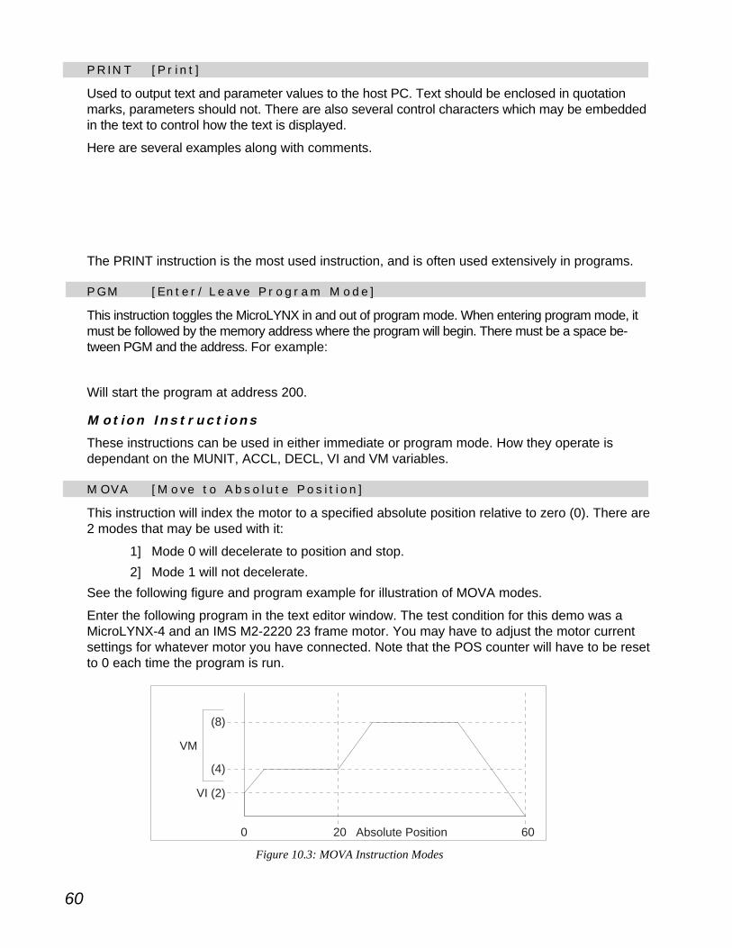
60
VM
(4)
(8)
VI (2)
0 20 60Absolute Position
Figure 10.3: MOVA Instruction Modes
P R I N T [ P r i n t ]
Used to output text and parameter values to the host PC. Text should be enclosed in quotationmarks, parameters should not. There are also several control characters which may be embeddedin the text to control how the text is displayed.
Here are several examples along with comments.PRINT IOS ‘Print the state of all I/O linesPRINT UVARS ‘Display the value of user-defined variablesPRINT ALL ‘Display the state of all VARS/FLGS/IOSPRINT ACCL ‘Display the value of the acceleration variablePRINT "\nAxis at position: " ,POS;
‘Display the text “Axis at position:” and the value of the POS counter‘embed a line feed with no carriage return
The PRINT instruction is the most used instruction, and is often used extensively in programs.
P G M [ E n t e r / L e a v e P r o g r a m M o d e ]
This instruction toggles the MicroLYNX in and out of program mode. When entering program mode, itmust be followed by the memory address where the program will begin. There must be a space be-tween PGM and the address. For example:
PGM 200
Will start the program at address 200.
Mot i o n I n s t r u c t i o n s
These instructions can be used in either immediate or program mode. How they operate isdependant on the MUNIT, ACCL, DECL, VI and VM variables.
M O VA [ M o v e t o A b s o l u t e P o s i t i o n ]
This instruction will index the motor to a specified absolute position relative to zero (0). There are2 modes that may be used with it:
1] Mode 0 will decelerate to position and stop.2] Mode 1 will not decelerate.
See the following figure and program example for illustration of MOVA modes.
Enter the following program in the text editor window. The test condition for this demo was aMicroLYNX-4 and an IMS M2-2220 23 frame motor. You may have to adjust the motor currentsettings for whatever motor you have connected. Note that the POS counter will have to be resetto 0 each time the program is run.

61
POS=0 'set position counter to 0
MUNIT=80000 'set motor units to 1 munit=80000msteps
MAC=50 'set acceleration current to 50%
MRC=50 'set run current to 50%
PGM 200 'start program at address 200
VM=4 'maximum velocity for index = 4 munits
MOVA 20,1 'index to abs. position 20, do not decel
HOLD 0 'supend program until pos. chg. completes
VM=8 'maximum velocity for index = 8 munits
MOVA 60 'index to abs. position 60, decel to stop.
HOLD 2
END
PGM
M O V R [ M o v e t o R e l a t i v e P o s i t i o n ]
This instruction will index the axis a specified number of munits relative to the current position.The two modes perform the same way as the MOVA instruction. The program above may beadapted by replacing the MOVA instructions with MOVR. The difference in operation will be thatthe POS counter will not need to be reset to 0 following program execution as MOVR will notindex the axis to an absolute position.
S L E W [ S l e w M o t o r a t C o n s t a n t Ve l o c i t y ]
This instruction will slew the motor at the velocity given in munits per second. It has two modes:
1] Mode 0: Use acceleration ramp.
2] Mode 1: Do not use acceleration ramp.
If the mode is not specified, then Mode 0 is assumed.
Example:SLEW 500000 ‘slew the motor at 500,000 munits/sec, use accel.
SLEW 200000,1 ‘slew the motor at 200,000 munits/sec, no accel.
Use of Mode 1 may cause the axis to stall depending on the motor, load and maximum velocity.
F I O S [ F i n d I / O S w i t c h ]
This instruction finds the designated home switch. By default it will find the home switch at thevelocity specified by VM, and back off of the home switch at the velocity specified by VI.
The speeds at which the instruction finds the switch may be set to something other than VM andVI if desired (i.e. FIOS <±speed>, <±creep>).
I /O I n s t r u c t i o n s
These instructions are used to read, write and configure the I/O and may be used in eitherimmediate mode or program mode. These instructions may also function as variables. They arecovered in detail in Section 8 of this document.
I O S [ I / O S e t u p ]
Sets the I/O parameters which identify the function of the I/O line or group.
I O [ R e a d Wr i t e I / O ]
62
P r og r am I n s t r u c t i o n s
Program instructions are instructions that control the sequence, timing and functionality of aMicroLYNX program.
L B L [ L a b e l P r o g r a m / S u b r o u t i n e ]
This instruction labels the proceeding program or subroutines within a program with a 1 - 8character alpha-numeric name. The name can also contain the underscore (_) character, noother characters are valid.
Program or subroutine labels can be used in program execution, or as the target for a programbranch or subroutine call.
Usage examples:LBL MY_SUB ‘declare subroutine named MY_SUB
PGM 100 ‘start program at address 100LBL MY_PROG ‘name prog MY_PROGMOVA 20 ‘move some distance
END ‘end programPGM ‘return to immediate mode
EXEC MY_PROG ‘run program MY_PROG
E N D [ E n d P r o g r a m ]
Designates the end of a program.
F L G [ D e f i n e U s e r F l a g ]
This instruction allows the user to declare a flag and set it to some state. The naming conven-tions for a user-defined flag are the same as for labels declared with the LBL instruction. Theseflags can be either global (declared in immediate mode) or local (declared within a program).Local flags are erased and re-declared again when a program is executed.
Usage Example:FLG MY_FLG=1 ‘declare flag MY_FLG, set to 1
This example shows a global flag being declared. To view the state of this flag and any otheruser-defined flags enter:
PRINT UFLGS
The response from the terminal would be:MY_FLG = G TRUE
The “G” would indicate that it is a global flag at a logic TRUE state. With a local flag, the “G”would be replaced with an “L”.

63
VA R [ D e f i n e U s e r Va r i a b l e ]
This instruction allows the user to declare a variable andset it to a value. The naming conventions for user-defined variables are the same as user-defined flagsdeclared with the FLG instruction. These variables canbe global (declared in immediate mode) or local (de-clared within a program). Local variables are erasedand re-declared when a program executed.
The following example is a short program that will declare a local variablenamed “LENGTH”, request an input from the user, then perform a relativeindex the distance specified. It will then loop back to the beginning andrequest input until the escape key is pressed.PGM 200 'start program at address 200
LBL VAR_TEST 'name the program VAR_TESTVAR LENGTH=0 'declare local variable LENGTH, set to 0PRINT "How far do I go?";INPUT LENGTH 'request input length in munitsMOVR LENGTH 'index relative distanc defined by LENGTHHOLD 2 'suspend program until motion completesPRINT "Went this far:", LENGTHBR 200 'loop to beginning of program
ENDPGM
I N P U T [ U s e r I n p u t R e q u e s t ]
This instruction allows for data to be entered into a variable from an external device such as aterminal or an HMI through the serial port(s).
See VAR example above for usage example.
D E L AY [ D e l a y P r o g r a m E x e c u t i o n ]
Delays program execution for a specified number of milliseconds.
For Example:DELAY 1000 ‘delay program execution for 1 second.
H O L D [ H o l d P r o g r a m E x e c u t i o n ]
The HOLD instruction differs from DELAY in that it suspends program execution until a specifiedmotion, velocity change, or position change completes. Typically, a “HOLD 2” will be issuedfollowing a MOVA or MOVR. This instructs the MicroLYNX to suspend the program until thepreviously instructed motion is complete.
B R [ B r a n c h ]
This instruction is capable of two different types of program branches:
1] Conditional.
2] Unconditional.
This instruction may be used in DO-WHILE loops and IF-THEN structures.
A conditional branch will branch to another program address or label when a flag or variablereaches a specified value or state. A conditional branch will be expressed thus:

64
‘this will conditional branch to labelLOOP_LBL,‘while variable LOOP_CNT is‘less than 50 [DO-WHILE.
BR LOOP_LBL, LOOP_CNT<50
‘this will conditional branch to address400‘when I/O line 21 = 1 [IF-THEN]
BR 400, IO 21
An unconditional branch will perform the program branch when reached,for example:
BR MY_PROG ‘loop to beginning of program
C A L L [ C a l l S u b r o u t i n e ]
This instruction allows the user to invoke a subroutine within a program. As with the branchinstruction, it may be conditional or unconditional. The condition can be set on a call in the samefashion as a condition on a branch.
The main difference in operation is that when a subroutine is called, at the end of a subroutine aRET (return from subroutine) statement must be in place. This will return to the line of codefollowing the CALL that originally invoked it.
The CALL instruction is expressed thus:‘this will call a subroutine‘labeled WAITIN21 when I/O‘line 21 becomes active
CALL WAITIN21, IO 21=1
LBL WAITIN21
MOVR 51200
HOLD 2
RET

65
F l a g s
Some flags may be used to enable/disable MicroLYNX functions. Other flags may be used toindicate system or program status. Flags may be either TRUE (1) or FALSE (0).
1] Factory-defined.
2] User-defined.
3] Special User-defined.
F a c t o r y
These flags are pre-defined at the factory and cannot be deleted. When an IP (Initialize Param-eters) instruction is given, these flags will be set to their factory default state. There are twotypes of factory-defined flags: Read/Writable and Read Only.
Use r
One of the powerful features of theMICROLYNXinstruction set is that it allows the user todefine flags both inside a program (local) or outside a program (global). User-defined flags aredeleted by means of the DVF (Delete Variables and Flags) instruction.
Usage o f F l a g s
Flags are typically used to set conditions for branches and subroutine calls. They are alsouseful for program debugging. For the definition of all the factory-defined flags, see the Micro-LYNX/LYNX Operating Instructuions on the CD.
Ke ywo r d s
Keywords are used in conjunction with the PRINT, GET and IP instructions to determine whatsub-set of the VAR/FLG/IOS will be acted upon by the instruction used. The keywords are:
ALL: Include all variables, flags and I/O states.
VARS: Include only variables.
FLAGS: Include only flags.
UVARS: Include only user-defined variables.
UFLGS: Include only user-defined flags.
IOS: Include only I/O line states.
STATS: Include only factory-defined status flags.

66
I n t r o d u c t i o n t o M i c r o LYNX P r o g r amm i n g
The MicroLYNX uses the LYNX Motion Control Programming Languange. This language is aneasy to use, BASIC-like language that follows standard programming conventions. It features apowerful instruction set that allows the user to control a wide spectrum of automated processes.
S yn t a x Ru l e s
1] The MicroLYNX Variables, Instructions and Flags are not case sensitive.2] A space is required after each command, except in the case where a variable or
flag is being set to some value or state. In this case no space is requiredbetween the command and the “equal” (=) sign or math function.
3] A comma is required as a delimiter between data fields or parameters wheremore than one data field or parameter is contained in the command. No space isrequired between delimiters and parameters.
4] The apostrophe ( ‘ ) is used as a comment character. Any text on the same lineafter the apostrophe will be ignored by the MicroLYNX.
5] Party mode device names defined by the DN instruction ARE case sensitive.
P r og r am Ru l e s
1] The first and last instruction of every program is the PGM instruction, whichtoggles the MicroLYNX in and out of program mode.
2] Subroutines invoked by a “CALL” must have a return “RET” instruction on the lastline of the subroutine.
Program Deve l opment Recommenda t i ons
There are several recommendations for program entry thatoptimize the user’s ability to edit and debug MicroLYNXprograms:
1] Always use the IMS Terminal text editorwindow or other ASCII text editor forprogram development. While programsmay be entered directly into theMicroLYNX via a terminal, the entireprogram has to be re-entered to edit or debug.
2] Use uppercase characters for instructions,variables and flags. While not casesensitive, this makes them stand out.
3] Comment heavily in lower case characters.4] Create subroutines in separate blocks instead of in the main program.5] Do not use word processor applications for program development as quotes and
apostrophes are handled differently and may not be recognized as such by theMicroLYNX!
MicroLYNX Programming 11

67
P r o g r a m D e v e l o p m e n t S t e p s
Like any project, successful development of a MicroLYNX program includes several plannedsteps. Following these steps in developing a program will reduce the time it takes to create acompleted, functioning program.
S t e p 1 : P l a n n i n g
Define what steps the program will take from start to end. A flowchart is the easiest way to dothis. Following is an example flowchart for a program that will move the motor a certain distanceat a certain velocity, reduce speed, activate an output, disable the output, cease motion andreturn to origin.
S t e p 2 : D e f i n e P a r ame t e r s
A program will typically perform functions such as monitor a switch, control a solenoid or relay,drive a motor, read an encoder, etc. In order for the program to react to external devicesthrough the I/O, the I/O parameters should be set before running the program.
Global variables or flags should also be defined at this point. Motion parameters should be setalso.
All these can be entered into the text editor. See program following next step for example.
Figure 11.1: Flowchart Used for Program Planning
START
Turn Output OFFat 10 Revs
Move to 4.25revs at 10 RPS
Stop Move At10.5 Revs
Reduce speedto 2 RPS
Return to Originat 10 RPS
Turn output onat 5 revs
ENDA
A

68
S t e p 3 : P r o g r am En t r y
The program is now entered into the text editor. The following program example is broken downinto its separate components for clarity. This example follows the plan illustrated in the flowchartFigure 11.1. This is a working program illustrating how an output can be switched on-the-flyusing the position trip functions. An LED can be connected to I/O line 21 and this program canbe entered as shown.
'******** Parameter Setup ********
MUNIT = 51200VI = 0.500ACCL = 20DECL = 50IOS 21 = 0,1,0 'set i/o 21 to:output - gen. purpose,
'active low
'******** Main Program ********
PGM 200LBL ONTHEFLY TP1 = 5, PSUB1 'configure 1st position trip at 5 revs TP2 = 10, PSUB2 'configure 2nd position trip at 10 revs TPE1 = 1 'enable both position trips TPE2 = 1 VM = 10 'initial max speed 10 rps MOVA 4.25, 1 'move out to 4.25 revs at 10 rps HOLD 0 VM = 2 'reduce max speed to 2 rps MOVA 10.5 'move to 10.5 revs HOLD 2 DELAY 250 VM = 10 'reset max speed to 10 rps MOVA 0 'return to origin HOLD 2 END
'******** Subroutines ********
LBL PSUB1 'turn on output at 5 revs. IO 21 = 1 RET
LBL PSUB2 'turn off output at 10 revs IO 21 = 0 RET
PGM
After the program is entered it can be downloaded to the MicroLYNX. If using the IMS Terminalprogram, this is as simple as clicking the menu item “Transfer > Download”. Otherwise, theprogram can be copied and pasted from the text editor to the terminal.
S t e p 4 : P r o g r am E x e c u t i o n
When a program is executed, it will run in the sequence in which it is written. There are basicallyfour methods of program execution:
1] Program executes on power-up: This is done by labeling the program“STARTUP”. Only one program in memory can have this label.

69
2] Program executes by label: The label of the program can be used as a keyword toexecute that program by typing the program label directly into the terminal inimmediate mode.
3] Program executes by input: An input can be defined to start a program, this isusually accomplished by using the GO dedicated input function.
4] Program executes by address: This method requires the use of the EXECinstruction. Typing “EXEC” followed by a space and the address where theprogram begins will execute the program.
S t e p 5 : P r o g r am Ed i t i n g/Debugg i n g
The final step in the MicroLYNX program development process is to debug and tweak the pro-gram to a state of perfection. Unless your program is no more advanced than “turn the motor xdistance and stop”, it will be a rare circumstance of a program working perfectly the first time.This is true in any programming language, be it BASIC, C++, Java or LYNX. There are severaltools built into the LYNX Motion Control Programming Language that assist the programmer indebugging. These are:
1] Error codes.
2] EXEC instruction modes:
EXEC <lbl/addr>,1: Trace mode, code printed to screen as it is run.
EXEC <lbl/addr>,2: Single step mode, single steps through program.
3] ONER: instruction accommodates the use of a subroutine to capture an errorlocation.
4] BREAK: Instruction allows the user to set break points within a program.
These and other program debugging tools are explained in greater detail in Appendix B:Troubleshooting.
P r og r am Samp l e s
The following program samples may be used either as templates or as a means of familiarizingyourself with the use of the LYNX Motion Control Programming Language. Each step is fullyexplained by comments.
Mot i o n S amp l e
This program will move the motor 100,000 steps each time it is executed.PGM 200 'enter program mode at address 200
LBL MO_SAMP 'label the program MO_SAMP
MOVR 100000 'move relative 100000 steps
HOLD 2 'suspend program until motion completes
END 'designate the end of the program
PGM 'exit program mode

70
I f - T h e n S amp l e
This program will loop until an input is pulled to ground. Use of this will require a switch con-nected between I/O line 22 and I/O GND.IOS 22=0,0,0 'set i/o 22 to gen. purpose input, active low
PGM 200 'start program at address 200
LBL IF_THEN 'name the program IF_THEN
MOVR 10000 'relative index 10000 steps
HOLD 2 'suspend program until motion completes
BR IF_THEN,IO 22=0 'IF i/o 22=inactive THEN branch to IF_THEN
MOVR -100000 'relative index -100,000 steps
HOLD 2 'suspend program until motion completes
END 'designate end of program
PGM 'exit program mode
Coun t i n g S amp l e
Each time this program senses an input, it will index the motor a short distance and count it. Asin the previous sample, this program requires the switch be connected between I/O line 22 andI/O GND.IOS 22=0,0,0 'set i/o 22 to gen. purpose input, active low
PGM 200 'start program at address 200
VAR COUNT=0 'declare local variable COUNT, set val to 0
LBL IN_CNT 'name the program IN_CNT
BR IN_CNT, IO 22=0 'if i/o 22=inactive, then branch to IN_CNT
LBL LOOP 'label process LOOP
BR LOOP, IO 22=1 'if i/o 22=1, then branch to LOOP
MOVR 10000 'relative index 10000
HOLD 2 'suspend prog. until motion completes
INC COUNT 'increment COUNT
PRINT "COUNT = " COUNT 'display value of COUNT
BR IN_CNT 'uncond. branch to IN_CNT
END
PGM
Use r I n t e r f a c e S amp l e
This sample program will ask the user for an absolute axis position, then index to that position.PGM 200
VAR POSITION=0 'declare local var POSITION
LBL LOOP 'name the program LOOP
PRINT "Enter an absolute position:";
INPUT POSITION 'wait for user to enter position
MOVA POSITION 'absolute index to POSITION
HOLD 2 'suspend program until motion completes
BR LOOP 'loop to beginning of program
END
PGM

71
Bac k a n d F o r t h
This program will move 1 revolution in a positive direction, then 1 revolution in a negative direc-tion, then repeat until the escape key on the terminal keyboard is pressed.MUNIT=51200/360 'set munits to degrees
PGM 200
LBL BNF 'label program BNF
MOVR 360 'index relative +360°
HOLD 2 'suspend program until move completes
MOVR -360 'index relative -360°
HOLD 2 'suspend program until move completes
BR BNF 'loop to beginning of program
END
PGM
Bac k a n d F o r t h P a r t 2
This program will move 1 revolution in a positive direction, print “Forth” to the terminal displayand wait two seconds. It will then turn 1 revolution in a negative direction, print “Back” to thedisplay, wait two seconds, then repeat until the escape key is pressed on the terminal keyboard.MUNIT=51200/360 'set munits to degrees
PGM 200
LBL BNF2 'label program BNF
MOVR 360 'index relative +360°
HOLD 2 'suspend program until move completes
PRINT "Forth"
DELAY 2000 'delay program 2 seconds
MOVR -360 'index relative -360°
HOLD 2 'suspend program until move completes
PRINT "Back"
DELAY 2000 'delay program 2 seconds
BR BNF2 'loop to beginning of program
END
PGM
F i n d I /O Sw i t c h S amp l e
This sample program will have a section that defines the parameters for the I/O and motionoutside of the program. To use this program, three switches must be placed between I/O lines21, 22, 23 and I/O GND. This program will set up three inputs: GO, STOP and a HOME switch.When executed by the GO switch the motor will seek the HOME input. When the HOME switchis pressed it will set the position counter to 0. The program will the run the motion profile.'********PARAMETERS*******
MUNIT=51200/1000 'set munits to 1000 steps/rev
IOS 21=9,0,0 'set i/o 21 as GO input, active low
IOS 22=10,0,0 'set i/o 22 as STOP input, active low
IOS 24=12,0,0 'set i/o 24 as HOME input, active low
VM=20 'set the maximum velocity to 20 munits/sec
VI=1 'set the initial velocity to 1 munit/sec

72
'*******PROGRAM *********
PGM 1 'start program at line 1
LBL PROG 'label the program PROG_1
FIOS 'find home switch
HOLD 2 'suspend program until motion completes
POS=0 'set position register to 0
MOVA 1000 'index absolute 1000 steps
HOLD 2 'suspend program until motion completes
DELAY 2000 'wait 2 seconds
MOVA 0 'index to absolute position 0
HOLD 2 'suspend program until motion completes
DELAY 2000 'wait 2 seconds
END
PGM

73
Sample Applications12These applications are the result of an informal survey conducted by the IMS ApplicationsEngineering Department to learn the most common MicroLYNX 1 and 1-1/2 axis applications.Each application example contains an application diagram, a flowchart and program code.
F e e d C u t 1
This program feeds a web to length and switches an output to operate a tool such as a cutter.The machine operator enters the feed length and batch count. The operation begins when theSTART button is pressed, and ends when the batch is complete or material runs out.
Feed Cut 1 applies to labeling, packaging, converting, etc.
Stepping Motor
MaterialSensor
Nip Rollers
Cutter
HumanMachineInterface
(HMI)
START
STOP
MicroLYNX Control
Module + StepMotor Driver
Figure 12.1: Feed Cut Application
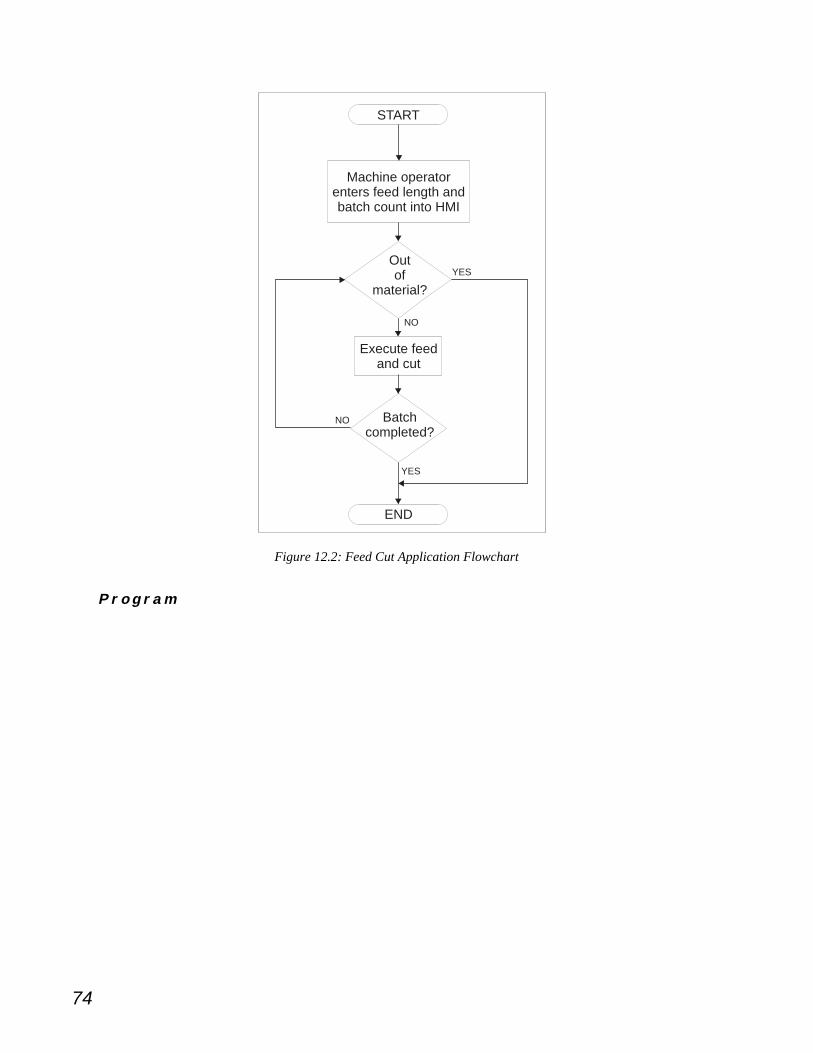
74
START
Machine operator enters feed length and batch count into HMI
Execute feedand cut
Outof
material?
Batchcompleted?
END
YES
YES
NO
NO
Figure 12.2: Feed Cut Application Flowchart
P r o g r a m
‘************* Parameter Setup ************
MUNIT = 51200 ‘One inch per rev @ 1/256 ustep
VI = 0.5 ‘Base speed 1/2 inch/sec
VM = 10 ‘Slew speed 2 inch/sec
ACCL = 20 ‘Accl = decl = 20 in/sec^2
DECL = 20
IOS 21 = 0,0,0 ‘Material Sensor: gen. purpose input active low
IOS 23 = 9,0,0 ‘IO 23 is a Start Input
IOS 24 = 10,0,0 ‘IO 24 is Stop Input
IOS 31 = 0,1,0 ‘Cutter output: GP, output, low true
VAR Feedlth
VAR TargetCt = 0
VAR Count = 0
VAR Matsens = 21
VAR Cutter = 31

75
‘************* Program ************
PGM 1
LBL FEEDCUT1
PRINT “Enter Feed Length “;
INPUT Feedlth
LBL Enterct
PRINT “Enter Total Parts Count “;
INPUT Targetct
BR Enterct, Targetct <= 0
LBL Mainloop
BR Webdone, ! IO Matsens ‘Production ends when the system
‘is out of material
MOVR Feedlth ‘Feed the material
HOLD 2
IO Cutter = 1 ‘Turn on the Cutter output
DELAY 100 ‘for 100 msec
IO Cutter = 0 ‘Turn off the Cutter output
INC Count
PRINT “Parts Made “, Count
BR Mainloop, Count < TargetCt
PRINT “Batch Complete”
PRINT Count, “ Parts Made”
BR Alldone
LBL Webdone
PRINT “BATCH INTERRUPTED”
PRINT Count, “ Parts Made”
PRINT “Out of Material”
LBL Alldone
END
PGM

76
R e a d a n d F e e d
This program reads the state of two inputs to determine a move distance, and makes themove.
Stepping Motor
MicroLYNX ControlModule + Step Motor Driver
BIT 0
BIT 1
STARTIO 22
IO 21
IO 23
IG
Figure 12.3: Read and Feed Application
START
Read Inputsto determine
move distance
Move selecteddistance
END
Figure 12.4: Read and Feed Application Flowchart

77
Read a n d F e e d P r o g r am Code
‘************* Parameter Setup ************
MUNIT = 51200
VI = 0.5
VM = 10
ACCL = 20
DECL = 20
IOS 21 = 0,0,0 ‘Distance Bit0, low true
IOS 22 = 0,0,0 ‘Distance Bit1, low true
IOS 23 = 9,0,0 ‘Start input, low true
VAR DISTANCE
VAR MASK = 3
VAR INPCODE
‘************* Program ************
PGM 1
LBL READFEED
INPCODE = IO 20 & 3 ‘This step masks the upper 4 bits of IO 20.
‘Feed distance is set in the routine depending on the
‘state of Inputs 21 & 22
BR Dist0, INPCODE = 0
BR Dist1, INPCODE = 1
BR Dist2, INPCODE = 2
BR Dist3, INPCODE = 3
LBL Feed
MOVR DISTANCE
HOLD 2
END
LBL Dist0
DISTANCE = 1
BR Feed
LBL Dist1
DISTANCE = 2
BR Feed
LBL Dist2
DISTANCE = 3
BR Feed
LBL Dist3
DISTANCE = 4
BR Feed
PGM

78
A N D - O R
This program shows how to read the state of two inputs and perform logical AND and OR onthem. For this example there is program code only.
AND - OR P r o g r am Cod e
‘******** Parameter Setup ********
IOS 21 = 0,0,0 ‘Distance Bit0, low true
IOS 22 = 0,0,0 ‘Distance Bit1, low true
IOS 23 = 9,0,0 ‘Start input, low true
FLG B0 ‘This flag stores Bit0
FLG NB0 ‘This flag stores NOT(Bit0)
FLG B1 ‘This flag stores Bit1
FLG NB1 ‘This flag stores NOT(Bit1)
FLG AND0 ‘This flag stores the result of NOT(Bit1) AND NOT(Bit0)
FLG AND1 ‘This flag stores the result of NOT(Bit1) AND Bit0
FLG AND2 ‘This flag stores the result of Bit1 AND NOT(Bit0)
FLG AND3 ‘This flag stores the result of Bit1 AND Bit0
FLG OR0 ‘This flag stores the result of NOT(Bit1) OR NOT(Bit0)
FLG OR1 ‘This flag stores the result of NOT(Bit1) OR Bit0
FLG OR2 ‘This flag stores the result of Bit1 AND NOT(Bit0)
FLG OR3 ‘This flag stores the result of Bit1 OR Bit0
VAR BIT0 = 21 ‘IO 21 is read into Bit0
VAR BIT1 = 22 ‘IO 22 is read into Bit1
‘******** Program ********
PGM 1
LBL ANDOR
‘The next four lines read the IO states, write
‘them into flags, and write the negatives into
‘flags.
B0 = IO BIT0
NB0 = !B0
B1 = IO BIT1
NB1 = !B1

79
‘The next four lines perform logical AND.
AND0 = NB1 & NB0
AND1 = NB1 & B0
AND2 = B1 & NB0
AND3 = B1 & B0
‘These next four lines print out the results of
‘the logical AND.
PRINT “/BIT1 & /BIT0 = “, AND0
PRINT “/BIT1 & BIT0 = “, AND1
PRINT “BIT1 & /BIT0 = “, AND2
PRINT “BIT1 & BIT0 = “, AND3
‘The next four lines perform logical OR.
OR0 = NB1 | NB0
OR1 = NB1 |B0
OR2 = B1 | NB0
OR3 = B1 | B0
‘These next four lines print out the results of
‘the logical OR.
PRINT “/BIT1 OR /BIT0 = “, OR0
PRINT “/BIT1 OR BIT0 = “, OR1
PRINT “BIT1 OR /BIT0 = “, OR2
PRINT “BIT1 OR BIT0 = “, OR3
END
PGM
On - T h e - F l y
This program illustrates how to change speeds and toggle outputs while moving. This applies toapplications where a tool needs to be moved quickly to the workpiece, then decelerated for fluiddispensing and work operations. On-The-Fly is an example of how MicroLYNX position tripswork.
IOS Motor+
Ball Screw
Position APOS=0
VM=10 RPSOutput OFF
Position BPOS=4.25VM=2 RPSOutput ON
@ 5 Revolutions
Position CPOS=10
Output OFF
Return to OriginVM=10 RPSSTART
FINISH
Figure 12.5: On-The-Fly Application

80
START
Turn Output OFFat 10 Revs
Move to 4.25revs at 10 RPS
Stop Move At10.5 Revs
Reduce speedto 2 RPS
Return to Originat 10 RPS
Turn output onat 5 revs
ENDA
A
Figure 12.6: On-The-Fly Application Flowchart
On - T h e - F l y P r o g r am Code
‘******** Parameter Setup ********
MUNIT = 51200
VI = 0.500
ACCL = 20
DECL = 50
IOS 31 = 0,1,0 ‘Output - general purpose, active low
‘******** Program ********
PGM 1
LBL ONTHEFLY
TP1 = 5, PSUB1 ‘Configure 1st position trip at 5 revs
TP2 = 10, PSUB2 ‘Configure 2nd position trip at 10 revs
TPE1 = 1 ‘Enable both position trips
TPE2 = 1
VM = 10 ‘Initial max speed 10 rps
MOVA 4.25, 1 ‘Move out to 4.25 revs at 10 rps
HOLD 0
VM = 2 ‘Reduce max speed to 2 rps
MOVA 10.5 ‘Move to 10.5 revs
HOLD 2
DELAY 250
VM = 10 ‘Reset max speed to 10 rps
MOVA 0 ‘return to origin
HOLD 2
END
LBL PSUB1 ‘Turn on output at 5 revs.
IO 31 = 1
RET
LBL PSUB2 ‘Turn off output at 10 revs
IO 31 = 0
RET
PGM

81
Reg i s t r a t i o n
This program feeds a web at a constant velocity and executes a registration move of a user-defined distance after a registration sensor becomes active. After the completion of the move,an output is switched ON/OFF. Operation starts when the START button is pressed and endswhen either the STOP button is pressed, the batch is complete, or material runs out.
Stepping Motor
MaterialSensorRegistration
Mark Sensor
Nip Rollers
Cutter
HumanMachineInterface(HMI)
START
STOP
MicroLYNXwith Differential IOExpansion Module
and Step Motor Driver
Figure 12.7: Registration Application

82
START
Execute feed, turncutter ON/OFF,
increment runningcount
Machine operator enters feed length and batch count into HMI
Feed material
Outof
material?
Batchcompleted?
RegistrationMark
Detected?
END
YESYES
YES
NO
NO
NO
A
A
Figure 12.8: Registration Application Flowchart
Reg i s t r a t i o n P r o g r am Code
‘******** Parameter Setup ********
MUNIT = 51200 ‘One inch per rev @ 1/256 microstepping
VI = 0.500 ‘Base speed 1/2" per rev
ACCL = 50
DECL = 50
IOS 21 = 9,0,0 ‘IO 21 is Start Input
IOS 22 = 10,0,0 ‘IO 22 is Stop Input
IOS 23 = 0,0,0 ‘IO 23 is Material Sensor
IOS 16 = 0,0,1 ‘Differential IO point configured as registration
‘sensor input.
IOF 10 = 0 ‘Give IO Group 10 highest speed response - 100ns
IOS 31 = 0,1,0 ‘Cutter output: GP, output, low true
VAR Speed
VAR Feedlth
VAR Matsens = 23
VAR Cutter = 31
VAR TargetCt ‘Number of parts to make
VAR Count = 0 ‘Running total

83
‘******** Program ********
PGM 1
LBL REGISTER
TI1 = 16 , MARK ‘Configure reg. sensor input trip routine
LBL Enterspd
PRINT “Enter feed speed (in/sec) “;
INPUT Speed
LBL Getdist
PRINT “Enter feed distance (in) “;
INPUT Feedlth
LBL Getcount
PRINT “Enter Batch Count “;
INPUT Targetct
LBL CRUISE
BR Webdone, !IO Matsens ‘Go to end if out of material
TIE1 = 1 ‘Enable input trip routine
SLEW Speed ‘Accelerate web up to speed.
LBL IDLER
BR IDLER, MVG ‘Wait for trip routine to complete execution
BR CRUISE, Count < Targetct ‘Execute as long as this condition
‘is true
PRINT “Batch Completed”
PRINT “Parts Made “, Count
LBL Webdone
END
LBL MARK
MOVR Feedlth
HOLD 2
IO Cutter = 1 ‘Turn on cutter output
DELAY 250 ‘for 1/4 sec
IO Cutter = 0 ‘Turn off cutter
INC Count ‘Increment Count by 1.
PRINT “Parts Made “, Count
RET
PGM

84
Tr a v e r s e
This program runs a traverse. The traverse axis follows quadrature encoder inputs from a takeup roll. The traverse, or follower axis, starts at the origin and travels in the positive direction tosome maximum positive position. It dwells for an adjustable number of master encoder counts.At this point, following starts in the negative direction until the maximum negative position isreached.
Traverse applies to winding applications using electronic gearing, or “lineshafting”.
Stepping Motor
MicroLYNXwith Differential IOExpansion Module
-OR-LYNX Control
Module with DifferentialIO Module and Step
Motor Driver
Linear Actuator
Origin PositiveLimit
Feed GuideFeed Guide
EncoderTake Up Roll
Figure 12.9: Traverse Application

85
START
Follow in thenegative direction
Follow in the positivedirection
Start at the origin
Disable Following
Disable Following
AtPositiveLimit?
AtOrigin?
DwellComplete?
DwellComplete?
YES
YES
YES
YES
NO
NO
NO
NO
A
A
Figure 12.10: Traverse Application Flowchart
Tr a v e r s e App l i c a t i o n P r o g r am Cod e
‘******** Parameter Setup ********
MUNIT = 400 ‘Drive set to half step
IOS 15 = 5,0,1,0,1,1
IOS 16 = 6,0,1,0,1,1
VAR ENCCT=480 ‘Encoder 120 quadrature
VAR FOLRATIO = MUNIT/ENCCT ‘Output Counts/Input Counts - 1:1
‘following with Lynx trainer
VAR DWELL = 480 ‘Dwell 480 counts at pos/neg limits
VAR DWELLPOS
VAR STARTPOS
‘******** Program ********
PGM 1
LBL TRAVERSE
POS = 0 ‘Start at 0
CTR3 = 0 ‘Clear Master Encoder counter
HAS = FOLRATIO

86
HAE = 1 ‘Enable following (half-axis operation)
LBL IDLE1
BR IDLE1, POS < 2 ‘Wait until the follower reaches 2 revs
HAE = 0 ‘Disable following
STARTPOS = CTR3
LBL IDLE2
DWELLPOS = CTR3 - STARTPOS
BR IDLE2, DWELLPOS < DWELL ‘Wait until master has turned
‘“Dwell” counts
HAS = -FOLRATIO ‘Reverse the following ratio
HAE = 1 ‘Enable following
LBL IDLE3
BR IDLE3, POS > 0 ‘Wait until follower returns to 0
HAE = 0 ‘Disable following
STARTPOS = CTR3
LBL IDLE4
DWELLPOS = CTR3 - STARTPOS ‘Wait until master has turned
BR IDLE4, DWELLPOS < DWELL ‘“Dwell” counts
HAS = FOLRATIO ‘Reverse the following ratio
HAE = 1 ‘Enable following
BR IDLE1 ‘Return to first loop
END
PGM

87
yrammuSteSnoitcurtsnIXNYLorciM
dnammoC noitpircseD egasU stinU/egnaR
LCCA elbairaVnoitareleccA >mun<=LCCA ces/STINURESU 2
LCA galFnoitareleccAylnOdaeRLCA,>rdda/lbl<RBLCA!,>rdda/lbl<RB
LCATNIRP
gnitareleccaton=*0gnitarelecca=1
TLCA elbairaVepyTnoitareleccA >marap<=TLCA 4-0
LBTLCA elbairaVelbaTnoitareleccA >lav<,>mun<=LBTLCA652-0=>mun<00.1-00.0=>lav<
SDA elbairaVputeStupnIgolanA >wal<,>cnuf<,>tinua<=>nahc<SDA launaMtcudorPeeS
NIA elbairaVlennahCtupnIgolanAdaeR >nahc<NIA=>rav<elbairaV=>rav<
2-1=>nahc<
LLA drowyeKsretemaraPllAeveirteR LLAPI,LLATEG,LLATNIRP -----
TUOA lennahCotegatloVgolanAtuptuO >lav<=>nahc<TUOAstnuoc5904-0=>lav<
4-1=>nahc<
DUAB elbairaVetaRDUAB >marap<=DUAB 83,91,*69,84
OIB galFedoMyraniB >1/0<=OIBIICSA=*0
yraniB=1
DGKBgninnuRmargorPdnuorgkcaB
galFylnOdaeR
DGKB,>rdda/lbl<RBDGKB!,>rdda/lbl<RB
DGKBTNIRP
gninnuRtoN*0=DGKBgninnuR1=DGKB
ADGKB elbairaVsserddAmargorPdnuorgkcaB ADGKBTNIRP 5718-1
ELBnoitasnepmoChsalkcaB
galFelbasiD/elbanE>1/0<=ELB
delbasiD=*0delbanE=1
MLB edoMnoitasnepmoChsalkcaB >edom<=MLBlacitamhtaM=*0
lacinahceM=1
HSLB tnuomAnoitasnepmoChsalkcaB >tinum<=HSLB STINUM
RB noitcurtsnIhcnarB >dnoc<,>rdda/lbl<RB launaMtcudorPeeS
KAERB elbairtaVtnioPkaerB >rdda/lbl<,>mun<=KAERBdelbasiD=*0
stnioPkaerB=01-1
YSB galFysuBylnOdaeR YSBTNIRPgninnur.gorpon=*0
gninnur.gorp=1
LLAC noitcurtsnIgnituorbuSllaC >dnoc<,>rdda/lbl<LLAC launaMtcudorPeeS
RVOMC evoMevitaleRdevaSllaC)raenil(>721-0<RVOMC)evruC-S(>1,0<RVOMC
-----
TDMOC emiTyaleDnoitacinummoC >lav<TDMOC sm00056-*0=>lav<
PC noitcurtsnImargorPraelC >edom<,>rdda/lbl<PC.gorp.cepsrlc=0
dneotrlc=1
LPC noitcurtsnItnemelpmoCsowT >glf,rav<LPCelbairaV=>rav<
galF=>glf<
ESCgalFelbanEmuSkcehC
)ylnOedoMyraniB(>1/0<=ESC
delbasiD=*0delbanE=1
Asterisk (*) indicates default.
Appendix A: Software Summary

88
yrammuSteSnoitcurtsnIXNYLorciM
dnammoC noitpircseD egasU stinU/egnaR
1RTC elbairaVretnuoC1kcolC launaMtcudorPeeS STINUM000,000,741,2±
2RTC elbairaVretnuoC2kcolC launaMtcudorPeeS STINUE000,000,741,2±
3RTC elbairaVretnuoC3kcolC launaMtcudorPeeSkcolC000,000,741,2±
61&51O/IsesluP
SAD elbairaVputeStuptuOgolanAotlatigiD >epyt<,>TINUA<=>nahc<SAD launaMeeS
LCD galFnoitareleceDylnOdaeR LCDTNIRPLCD,>rdda/lbl<RBgnitarelecedton=*0
gnitareleced=1
TLCD elbairaVepyTnoitareleceD >marap<=TLCD 4-0
CED noitcurtsnIelbairaVtnemerceD >rav<CED -----
LCED elbairaVnoitareleceDkaeP >mun<=LCED ces/STINURESU 2
YALED noitucexEmargorPyaleD >emit,YALED sm53556-0
PSID elbairaVyalpsiDtamroF launaMeeS -----
NDelbairaVemaNeciveD
)ylnOedoMytraP(>rahc<=ND
retcarahCIICSA9-0,z-a,Z-A
NEVRD galFelbasiD/elbanEevirD >1/0<=NEVRDdelbasiD=0delbanE=*1
SRVRD galFteseRevirD >1/0<=SRVRDteseRtoN=*0evirDteseR=1
PTVRD elbairaVepyTevirDylnOdaeR PTVRDTNIRPH384MI=2H508MI=4
FVDdnaselbairaVdenifeD-resUeteleD
noitcurtsnIsgalF,>2marap<,>1marap<FVD
>3marap<launaMtcudorPeeS
OHCE elbairaVedoMohcE >edom<OHCE
xelpuDlluF=*0xelpuDflaH=1
ohcEoN=2etaidemmmIohcE=3CEXEretfadnammoC
BDE elbiraVdnabdaeDredocnE >stinue<=BDE stinuE53556-0
EE galFelbasiD/elbanEredocnEretsaM >1/0<=EEdelbasiD=*0
delbanE=1
DNE noitcurtsnImargorPdnE DNE -----
RRE galFrorrEylnOdaeR RRETNIRProrrEoN=*0stsixErorrE=1
ARRE elbairaVsserddArorrEylnOdaeR ARRETNIRP -----
RORRE elbairaVepyTrorrE RORRETNIRPnielbaTrorrEeeS
launaMsihtfoCxidneppA
CSE galFtceleSretcarahCepacsE >glf<CSECSE*0=>glf<
E^LRTC1=>glf<
TINUE elbairaVstinUredocnE >mun<=TINUEresUrepstnuoCredocnE
tinU
CEXE noitcurtsnImargorPetucexE >edom<,>rdda/lbl<CEXElamroN=0
edoMecarT=1petSelgniS=2
TLUAF galFelbasiD/elbanErotacidnItluaF >1/0<=TLUAFdelbasiD=0delbanE=*1
Asterisk (*) indicates default.

89
yrammuSteSnoitcurtsnIXNYLorciM
dnammoC noitpircseD egasU stinU/egnaR
SOIF noitcurtsnIhctiwSO/IdniF launaMtcudorPeeS -----
SGALF drowyeKsgalFeveirteR,SGALFTEG,SGALFTNIRP
SGALFPI-----
GLF noitcurtsnIgalFresUenifeD >leman<GLF
8ot1=>eman<ciremunahplA+sretcarahC
)_(erocsrednu
EHCEG galFelbasiD/elbanEohcElabolG >1/0<=EHCEGdelbasiD=*0
delbanE=1
TEGsgalFdnaselbairaVeveirteR
noitcurtsnI,SGALFTEG,SRAVTEG
LLATEG-----
EAH galFelbasiD/elbanEedoMsixAflaH >1/0<=EAHdelbasiD=*0
delbanE=1
SAH elbairaVgnilacSedoMsixAflaH >mun<=SAH 1– ≤ 1<mun
TDCH elbairaVemiTyaleDtnerruCdloH >emit<=TDCH sm53556-0
DLEHdleHnoitucexEmargorPylnOdaeR
galFDLEHTNIRP
gninnuR.gorP=*0dleH.gorP=1
DLOHagniruDnoitcurtsnImargorPdloH
noitcurtsnIevoM>edom<DLOH
.gnhC.soP=0.gnhC.leV=1
noitoM=2
TSOH galFelbasiD/elbanEecafretnItsoH >1/0<=TSOHdelbasiD=*0
delbanE=1
CSJI noitcurtsnIkcitsyoJetarbilaC CSJI -----
CNI noitcurtsnIelbairaVtnemercnI >rav<CNI -----
PNI galFsutatSgnidnePtupnI >glf<=PNI*)0(ESLAF=>glf<
)1(EURT=>glf<
TUPNI noitcurtsnItseuqeRtupnIresU >marap<,>rav<TUPNI.gorP.psuS=0
gorP.tnoC=1
1TUPNInoitcurtsnItseuqeRtupnIresU
)1MMOCXNYL(>marap<,>rav<1TUPNI
.gorP.psuS=0
.gorP.tnoC=1
2TUPNInoitcurtsnItseuqeRtupnIresU
)2MMOCXNYL()marap(,>rav<2TUPNI
.gorP.psuS=0
.gorP.tnoC=1
OI elbairaVO/IetirWdaeR tnemucoDsihtfo8noitceSeeS
FOI elbairaVgniretliFtupnIlatigiD tnemucoDsihtfo8noitceSeeS
SOI elbairaVnoitarugifnoCO/I tnemucoDsihtfo8noitceSeeS
PI noitcurtsnIsretemaraPezilaitinI >drowyek<PI,SGALF,SRAV,LLA
SOI
SGOJ elbairaVdeepSgoJ >deeps<=SGOJRESU=>deeps<
ces/TINU
CSJ elbairaVnoitisoPretneCkcitsyoJ >mun<=CSJ TINUA5904-0=>mun<
BDSJ elbairaVdnabdaeDkcitsyoJ >mun<=BDSJ TINUA5904-0=>mun<
ESJ galFelbasiD.elbanEkcitsyoJ glf<=SJ)delbasiD(*0=>glf<
delbanE=1>glf<
SFSJ elbairaVelacSlluFkcitsyoJ >mun<=SFSJ TINUA5904-0=>mun<
Asterisk (*) indicates default.

90
yrammuSteSnoitcurtsnIXNYLorciM
dnammoC noitpircseD egasU stinU/egnaR
ECHSJdnakcitsyoJnehwtnerruCdloHelbanE
oreZtaeragoJ>glf<=ECHSJ
delbasiD0=>glf<delbanE*1=>glf<
LBL noitcurtsnIenituorbuS/margorPlebaL >eman<LBLciremunahplA8ot1)_(erocsrednudna
TLCDL elbairaVepyTnoitareleceDtimiL >marap<=TLCDL 4-0=>marap<
LCEDL elbairaVnoitareleceDtimiL >mun<=LCEDLRESU=>mun<
ces/TINU 2
PTSMIL galFpotStimiL >1/0<=PTSMILgorPpotSt'noD=*0
margorPpotS=1
TSIL noitcurtsnIecapSmargorPderotStsiL >edom<,>rdda/lbl<TSILDNEts1ottsiL=0
llatsiL=1
KCOL ecapSmargorPkcoL >glf<=KCOL)delbasiD(*0>glf<
delbanE1>glf<
OGOL galFelbasiD/elbanErennaBnO-ngiS >glf<=OGOLdelbasiD0>glf<delbanE*1>glf<
CAMnoitareleccArotoM
elbairaVgnitteStnerruC>tnecrep<=CAM %001-0
CHM elbairaVgnitteStnerruCdloHrotoM >tnecrep<=CHM %001-0
AVOM noitcurtsnInoitisoPetulosbAotevoM >edom<,>sop<AVOMetareleceD=*0
leceDtoNoD=1
RVOM noitcurtsnInoitisoPevitaleRotevoM >edom<,>sop<RVOMetareleceD=*0
leceDtoNoD=1
CRM elbairaVgnitteStnerruCnuRrotoM >tnecrep<=CRM %001-0
TDSM elbairaVemiTyaleDgniltteSrotoM >emit<=TDSM sm53556-0
LESM elbairaVtceleSnoituloseRrotoM tnemucoDsihtfo7noitceSeeS
TINUM elbairaVstinUrotoM >mun<=TINUMsesluPkcolC=>mun<
tinUresUrep
GVM galFgnivoMylnOdaeRGVMTNIRP
GVM,>rdda/lbl<RByranoitatS=*0
gnivoM=1
PON noitcurtsnInoitarepOoN PON -----
RENO noitcurtsnIrorrEnO >rdda/lbl<RENO -----
YTRAP galFelbasiD/elbanEedoMytraP >1/0<=ytraPdelbasiD=*0
delbanE=1
SUAP noitcurtsnInoitucexEmargorPesuaP SUAP -----
DSUAP galFdesuaPmargorPylnOdaeR DESUAPTNIRPdesuaPtoN=*0
desuaP=1
MSUAP elbairaVedoMesuaP >edom<=MSUAP5-*0=>edom<
launaMtcudorPeeS
GHCP galFegnahCnoitisoPylnOdaeRGHCPTNIRP
GHCP,>rdda/lbl<RByranoitatS=*0
gnignahC.soP=1
TMFP elbairaVtamroFtnirP launaMtcudorPeeS
MGP elbairaVedoMmargorPtixE/retnE>rdda<MGP
MGPmargorPretnE
margorPtixE
MGP drowyeKmargorPeveirteR MGPTEG -----
EMPelbasiD/elbanEecnanetniaMnoitisoP
galF>1/0<=EMP
delbasiD=*0delbanE=1
Asterisk (*) indicates default.

91
yrammuSteSnoitcurtsnIXNYLorciM
dnammoC noitpircseD egasU stinU/egnaR
CCHMPtnerruCdloHecnanetniaMnoitisoP
elbairaVegnahC>tnecrep<=CCHMP %001ot0
VMP elbairaVyticoleVecnanetniaMnoitisoP >deeps<=VMPRESU=>deeps<
.ces/TINU
SOP elbairaVnoitisoPsixA>noitisop±<=SOP
SOPTNIRPRESU=>noitisop<
STINU
PACSOP elbairaVpirTfoemiTtanoitisoPsixA PACSOPTNIRP stinUresU
TNIRP noitcurtsnITNIRP launaMeeS
1TNIRP noitcurtsnI1MMOCXNYLotTNIRP launaMeeS
2TNIRP noitcurtsnI2MMOCXNYLotTNIRP launaMeeS
TPMRP elbairaVretcarahCtpmorPyficepS >iicsa/rahc<=TPMRP 452-23
DEUQ galFrellortnoCXNYLeueuQ >glf<=DEUQdelbasiD*0=glf
delbanE1=glf
OITAR elbairaVedoMoitaR >mun<=OITAR 2– ≤ 2<mun
EOITAR galFelbanEedoMoitaR >1/0<=OITARdelbasiD=*0
delbanE=1
WOITAR elbairaVhtdiWesluPedoMoitaR >mun<=WOITARevaWerauqS=*0
sn05452-1=1stnemercnI
SER noitcurtsnInoitucexEmargorPemuseR SER -----
TER noitcurtsnIenituorbuSmorFnruteR TER -----
DFTR noitcurtsnIstluafeDyrotcaFotnruteR DFTR ----
NUR noitcurtsnIksaTdnuorgkcaBnuR >rdda/lbl<NUR -----
EVAS noitcurtsnIevaS EVAS -----
RES elbairaVrebmuNlaireS RESTNIRP -----
TES noitcurtsnIgalFroelbairaVteS >lav<=>galf/rav<TES -----
WELSyticoleVtnatsnoCtarotoMehtwelS
noitcurtsnI>edom<,>deeps±<WELS
leccAesU=0>edom<pmaR
esUt'noD=1>edom<pmaRleccA
RVOMS evoMevitaleRevaS >tsid<>col<RVOMS)raeniL(721-0=>col<)evruC-S(1-0=>col<
)seulaVRVOM(=>tsid<
PTSS noitcurtsnIpotStfoS >edom<PTSSylnOnoitoMpotS=*0
.gorP&noitoMpotS=1
LLATS galFdellatSsixAylnOdaeRLLATSTNIRP
LLATS,>rdda/lbl<rBdellatStoN=*0
dellatS=1
STATS drowyeKsutatSeveirteR STATSTNIRP -----
WPETS elbairaVhtdiWesluPkcolCpetS >mun<=WPETSevaWerauqS=*0
sn05452-1=1stnemercnI
KTS galFtluaFkcatSenituorbuSylnOdaeRKTSTNIRP
KTS,>rdda/lbl<RBtluaFoN=*0
tluaF=1
EDLTS galFelbasiD/elbanEtceteDllatS >1/0<=EDLTSdelbasiD=*0
delbanE=1
MDLTS elbairaVedoMnoitceteDllatS >edom<=MDLTSrotoMpotS=*0
rotoMpotSt'noD=1
Asterisk (*) indicates default.

92
yrammuSteSnoitcurtsnIXNYLorciM
dnammoC noitpircseD egasU stinU/egnaR
FLTS elbairaVrotcaFllatS >mun<=FLTS STINURESU=>mun<
4IT-1IT selbairaVtupnInopirT launaMtcudorPeeS
4EIT-1EIT sgalFelbasiD/elbanEtupnInopirT >glf<=>x<EIT4-1=>x<
delbasiD*0=glfdelbanE1=glf
4PT-1PT selbairaVnoitisoPnopirT launaMtcudorPeeS
4EPT-1EPT sgalFelbasiD/elbanEnoitisoPnopirT >glf<=>x<EPT4-1=>x<
delbasiD*0=glfdelbanE1=glf
4TT-1TT seulaVremiTnopirT launaMtcudorPeeS
4ETT-1ETT sgalFelbasiD/elbanEremiTnopirT >glf<=>x<ETT4-1=>x<
delbasiD*0=glfdelbanE1=glf
4RTT-1RTT galFdaoleRremiTnopirT >glf<=>x<RTT4-1=>x<
taepeRtnoD*0=glftaepeR1=glf
VT elbairaVyticoleVnopirT launaMtcudorPeeS
EVT galFelbasiD/elbanEyticoleVnopirT >glf<=EVTdelbasiD*0=glf
delbanE1=glf
SGLFU drowyeKsgalFdenifeD-resUtropeR SGLFUTNIRPlabolG=etatScigoL+G
lacoL=etatScigoL+L
SLBLUslebaLmargorPdenifeD-resUtropeR
drowyeKSLBLUTNIRP sserddA+LBL
SRAVUselbairaVdenifeD-resUtropeR
drowyeKSRAVUTNIRP
labolG=etatScigoL+GlacoL=etatScigoL+L
EAV galFelbanEgolanAotyticoleV >glf<=EAVdelbasiD*0=>glf<
delbanE1=>glf<
RAVelbairaVdenifeD-resUeralceD
noitcurtsnI>mun<=>eman<RAV
8ot1=>eman<sretcarahCciremunahplA
)_(erocsrednu+rebmuNemoS=>mun<
SRAV drowyeKselbairaVeveirteR,SRAVTEG,SRAVTNIRP
SRAVPI-----
GHCV galFgnignahCyticoleVylnOdaeRGHCVTNIRP
GHCV,>rdda/lbl<RBtnatsnoCyticoleV=*0
gnignahCyticoleV=1
LEV elbairaVyticoleVylnOdaeRLEVTNIRP
>mun<=LEV,>rdda/lbl<RB.ceS/stinUresU=>mun<
REV elbairaVnoisreVerawtfoSylnOdaeR REVTNIRP launaMtcudorPeeS
IV elbairaVyticoleVlaitinI >mun<=IV .ceS/stinUresU=>mun<
MV elbairaVyticoleVmumixaM >mun<=MV .ceS/stinUresU=>mun<
Asterisk (*) indicates default.

93
B e g i n n i n g t o Tr o u b l e s h o o t
In the event that your MicroLYNX System doesn’t oper-ate properly the first step is to identify whether theproblem is electrical or mechanical in nature. The nextstep is to isolate the system component that is causingthe problem. As part of this process you may have todisconnect the individual components that make up yoursystem and verify that they operate independently. It isimportant to document each step in the troubleshootingprocess. You may need this documentation to refer back
to at a later date, or these details will greatly assist one of our application engineersin determining the problem should you need assistance.
Many of the problems that effect motion control systems can be traced to electricalnoise, software errors or mistakes in wiring.
Tr o u b l e s h o o t i n g C ommun i c a t i o n s
In the event that you are unable to establish communications with your MicroLYNX,check the following:
1] Verify wiring and connections.
2] Verify that the “Upgrade” switch is in the “OFF” state.
3] Verify proper communications port selection by jumping pins RX and TX on the 9pin or 25 pin connector on the host PC and observing loop-back echo.
4] If using a laptop with an RS-232 to RS-422 converter, note that some laptops areunable to support the converter due to power constraints.
5] Verify that the terminal settings such as BAUD rate, data bits and flow controlare set to 8, N, 1.
Tr o u b l e s h o o t i n g S o f t w a r e
The MicroLYNX features a FAULT LED and error codes that may give the source of the error. Itis a good rule of thumb to clear all programs (CP 1,1 followed by SAVE), variables and flags(DVF), and restore the factory defaults (IP). You may then retransfer the program to theMicroLYNX and attempt to run it again. If the program still fails you can use the tracingfunctions of the EXEC command to further isolate the problem.
To assist you in troubleshooting errors, the FAULT LED on the MicroLYNX can be enabled ordisabled
Setting the FAULT flag to a TRUE (1) state will cause the LED to illuminate when a systemerror occurs.
Using the LED in conjunction with the Error Table, Appendix C of this document, as well as thefollowing instructions can be used to identify and isolate errors in your program.
Appendix B: Troubleshooting

94
P R I N T
ERROR - Gives the Code to reference against the error table (Appendix B).
ERR - Prints the Error Flag Status, if visibility of the FAULT LED is impaired.
ERRA - Prints the Error code and NVM location of the error occurrence.
POS - Prints the Motor Position in User Units.
CTR2 or CTR3 - Prints the count of clock in or out.
IO - Prints the states of the Inputs and Outputs.
IOS - Prints the I/O settings.
VARS - Prints all Variables.
EXEC
Trace Mode = 1 (Usage EXEC [Program Label], 1) - Program Code is printed to screen as it isexecuted.
Single Step Mode = 2 (Usage EXEC [Program Label], 2) - Program Code is printed to thescreen one command at a time.
BREAK
The break command specifies an address at which the program will run at normal speed until itreaches the break. The user can then use the spacebar to single step the execution of programcode.
ONER
Subroutine can be run that stores the position upon time of error so that the error can be betterisolated.
Subroutine can also be run to print the error code.
I P
ALL or left blank - All variables, flags and I/O settings are initialized to factory defaults.
VARS - Variables are initialized to factory defaults.
FLAGS - Flags are initialized to factory defaults.
IOS - I/O settings are initialized to factory defaults.
DVF
Blank - Delete all user-defined flags and variables.
1, 2 - Delete only local user-defined variables.
0, 2 - Delete all local user-defined flags and variables.
L I S T
Prints the programs that reside in program memory.

95
PA U S
Pauses execution of program.
E r r o r C od e s
The error codes are subdivided into the following groups to help you identify the type of errorthat is occurring:
1000 - Hardware Errors
2000 - I/O Errors
3000 - Clock Errors
4000 - Syntax Errors
5000 - Variable/Flag Errors
6000 - Motion Errors
7000 - Encoder Errors
8000 - NVM Errors
9000 - Out of Range Errors
C o n t a c t i n g A p p l i c a t i o n S u p p o r t
In the event that you are unable to isolate the problem with your MicroLYNX System, the firstaction you should take is to contact the distributor from whom you originally purchased yourMicroLYNX or IMS Application Support at 860-295-6102 or by fax at 860-295-6107.
If you call IMS, it is best that you first fax both a wiring diagram and either the program youwrote or the system flow chart. Be prepared to answer the following questions:
1] What is the application?
2] In detail, how is the system configured?
3] With what external equipment is the system interfaced?

96
Appendix C: Error Table0 NO ERROR
Ha r dwa r e E r r o r s1018 IO MODULE NOT INSTALLED.1019 LYNX/MicroLYNX CHECK SUM INCORRECT.1020 ONLY ALLOWED IN IMMEDIATE MODE.1100 FAULT/LIMIT DETECTED IN A CONNECTED DRIVE. (Power OV/OC; Phase OC; Drive OT)1101 FAULT IN DRIVE 1.1105 DRIVE 1 FAULT AND TYPE CHANGED.1109 DRIVE 1 MSEL COULD NOT BE SET.1113 DRIVE 1 TYPE CHANGED, MSEL COULD NOT BE SET.1117 DRIVE 1 FAULT, MSEL COULD NOT BE SET.1121 DRIVE 1 FAULT, TYPE CHANGED, MSEL COULD NOT BE SET.1125 HOLD IGNORED, MOTOR DISABLED.1126 DRIVE 1 NOT AVAILABLE.1130 DRIVE 1 TYPE CHANGED.1134 ILLEGAL DRIVE NUMBER.1135 DRIVE 1 IN LIMIT.1139 TRIED TO SET MAC OR MRC TO LESS THAN ONE.1201 SELECTED ANALOG BOARD NOT INSTALLED.1202 ANALOG CHANNEL NUMBER NOT AVAILABLE.1204 ANALOG OPTION NOT INSTALLED.1205 ANALOG VALUE OUT OF RANGE, POSSIBLY DEFECTIVE BOARD.
I / O E r r o r s2001 FIOS FOUND NO (HOME) SWITCH.2002 NOT IN FACTORY MODE.2020 OUTPUT FAULT AT DIGITAL IO GROUP 20.2021 OUTPUT FAULT AT DIGITAL IO LINE 21.2022 OUTPUT FAULT AT DIGITAL IO LINE 22.2023 OUTPUT FAULT AT DIGITAL IO LINE 23.2024 OUTPUT FAULT AT DIGITAL IO LINE 24.2025 OUTPUT FAULT AT DIGITAL IO LINE 25.2026 OUTPUT FAULT AT DIGITAL IO LINE 26.2030 OUTPUT FAULT AT DIGITAL IO GROUP 30.2031 OUTPUT FAULT AT DIGITAL IO LINE 31.2032 OUTPUT FAULT AT DIGITAL IO LINE 32.2033 OUTPUT FAULT AT DIGITAL IO LINE 33.2034 OUTPUT FAULT AT DIGITAL IO LINE 34.2035 OUTPUT FAULT AT DIGITAL IO LINE 35.2036 OUTPUT FAULT AT DIGITAL IO LINE 36.2040 OUTPUT FAULT AT DIGITAL IO GROUP 40.2041 OUTPUT FAULT AT DIGITAL IO LINE 41.2042 OUTPUT FAULT AT DIGITAL IO LINE 42.2043 OUTPUT FAULT AT DIGITAL IO LINE 43.2044 OUTPUT FAULT AT DIGITAL IO LINE 44.2045 OUTPUT FAULT AT DIGITAL IO LINE 45.2046 OUTPUT FAULT AT DIGITAL IO LINE 46.2050 OUTPUT FAULT AT DIGITAL IO GROUP 50.2051 OUTPUT FAULT AT DIGITAL IO LINE 51.2052 OUTPUT FAULT AT DIGITAL IO LINE 52.2053 OUTPUT FAULT AT DIGITAL IO LINE 53.2054 OUTPUT FAULT AT DIGITAL IO LINE 54.2055 OUTPUT FAULT AT DIGITAL IO LINE 55.2056 OUTPUT FAULT AT DIGITAL IO LINE 56.2101 ANALOG RANGE NOT ALLOWED.

97
2102 ANALOG DESTINATION/SOURCE NOT ALLOWED.2103 ANALOG DESTINATION/SOURCE ALREADY USED.2104 INVALID ANALOG CHANNEL NUMBER.2105 ANALOG LAW NOT ALLOWED.2106 CAN’T ENABLE JOYSTICK WHILE IN MOTION OR CAN’T EXEC MOTION CMD WITH JOYSTICK ENABLED.2200 CAN ERRORS: 1-6,11-16,21-26,31-36.
C l o c k E r r o r s3001 TRIED TO SET CLK TO NON CLOCK LINE OR WRONG LINE.3002 CAN’T HAVE CLOCK TYPE APPLIED TO IT.3003 CAN’T HAVE RATIO AND NO_CLK.3004 CLK IO CAN’T BE SET FOR RATIO MODE.3005 IN HALF-AXIS MODE.3006 TRIED TO SET TO INPUT WHEN DRIVE CONNECTED.3007 NO IO SET FOR INPUT + RATIO.
S yn t a x E r r o r s4001 INVALID IO NUMBER.4002 TRIED TO WRITE GROUP TO NONUSER.4003 TRIED TO WRITE TO A NON-USER LINE.4004 TRIED TO WRITE TO AN INPUT.4005 TRIED TO SET AN OUTPUT ONLY TO INPUT.4006 TRIED TO SET AN INPUT ONLY TO OUTPUT.4007 TRIED TO SET LINE TYPE TO LINE THAT CAN’T BE SET THAT WAY.4008 NOT A VALID IO TYPE.4009 IO TYPE SW. PREVIOUSLY DEFINED.4010 FIND SW MUST BE SET AS INPUT.4011 MORE THAN ONE IO SET FOR RATIO INPUT.4012 ILLEGAL RUN/EXEC MODE.4013 RECEIVED UNACCEPTIBLE COMMAND.4014 ILLEGAL PAR IN “INPUT PAR” COMMAND.4015 LABEL HAS TO BE TEXT.4016 ILLEGAL DATA ENTERED IN PRINT FORMAT.4017 NO DATA ENTERED, COMMAND IGNORED.4018 ILLEGAL DRIVE NAME.4019 ADDRESS DOESN’T POINT TO VALID INSTRUCTION.4020 TRIED TO EXECUTE A BAD USER PROGRAM INSTRUCTION.4021 ILLEGAL LINE NUMBER.4022 MULTI LINE PRINTS NOT ALLOWED IN BINARY MODE.4023 ILLEGAL HOLD TYPE.4024 NOT ALLOWED IN IMMEDIATE MODE.4025 AN INPUT IS ALREADY PENDING.4026 SELECTED COMM, PORT2, CANNOT BE SEPERATELY SELECTED.4027 LINE NUMBER NOT NEEDED.4028 INP CANNOT BE SET.4029 ARRAY POINTER TOO LARGE (ACTBL OR SMOVR).4030 COMM TIMED OUT.4031 SMOVR ELEMENT NOT PROGRAMMED.4032 BINARY COMM CHECKSUM FAILED.
Va r i a b l e / F l a g E r r o r s5001 ILLEGAL VARIABLE ENTERED.5002 ILLEGAL FLAG ENTERED.5003 ILLEGAL FLAG OR VARIABLE ENTERED.5004 NO EQUAL IN: SET VARIABLE TO VALUE.5005 ILLEGAL CHARACTER FOLLOWS DECLARATION OF VARIABLE OR FLAG.5006 UNDEFINED USER VAR OR FLG.5007 TRIED TO REDEFINE LBL/VAR/FLG.5008 TRIED TO REDEFINE GBL/LCL LBL/VAR/FLG.5009 INSTRUCTION/VARIABLE/FLAG NOT IMPLEMENTED IN THIS VERSION.

98
5010 VALUE OF LBL/VAR/FLG CHANGED - WARNING.5011 FLAG IS READ ONLY.5012 VARIABLE IS READ ONLY.5013 CAN ONLY INIT ALL, VARS, FLAGS.5016 CAN’T SET MULTI VARIABLES, READ ONLY.
Mot i o n E r r o r s6001 REACHED PLUS LIMIT SW.6002 REACHED MINUS LIMIT SW.6003 TIME NEEDED TO MAKE MOVE LESS THAN 200USEC.6004 NO DISTANCE FOR MOVE.
En c od e r E r r o r s7001 STALL DETECTED.7002 IMPROPER RATIO OF MUNIT TO EUNIT.7003 MOVED OUT OF DEADBAND.7004 CAN’T FIND POSITION AT END OF MOVE.7005 STALLED WHILE DOING POSITION MAINTENANCE.7006 STALLED WHILE DOING EE POSITION CORRECTION AT END OF MOVE.
N V M E r r o r s8001 LABEL AREA FULL.8002 SAVE FAILED.8003 TRIED TO TAKE FROM EMPTY STACK.8004 DATA NOT IN NVM.8005 TRIED TO OVER FILL FOREGROUND STACK.8006 TRIED TO SAVE WHILE MOTION IN PROGRESS.8007 TRIED TO OVER FILL BACKGROUND STACK.8008 BAD SECTOR IN PAGE 0 OF FLASH.8009 BAD SECTOR IN PAGE 1 OF FLASH.8010 BAD SECTOR IN PAGE 2 OF FLASH.8011 BAD SECTOR IN PAGE 3 OF FLASH.
O u t O f R a n g e E r r o r s9001 IO FILTER OUT OF RANGE.9002 IO GROUP OUT OF RANGE.9003 PROGRAM ADDRESS OUT OF RANGE.9004 RATIO OUT OF RANGE.9005 DATA OUT OF RANGE FOR VARIABLE.9006 PULSE WIDTH OUT OF RANGE.9007 TOO MANY DIGITS SPECIFIED IN PRINT FORMAT.9008 SUM OF ID AND FD EXCEEDS MAX NUMBER OF DIGITS.9009 VALUE MUST BE POSITIVE ONLY.9010 VM IS SET LESS THAN OR EQUAL TO VI.9011 VI IS SET BELOW MIN_VELOCITY.9012 MOVE DISTANCE TOO SHORT FOR PRESENT DECEL RATE.9013 JOG SPEED LESS THAN MIN_VELOCITY.9014 ANALOG INPUT NOT ALLOWED FOR DATA.9015 COMM PORT OUT OF RANGE.9016 PROGRAM LOCKED, CLEAR PROGRAM OR RETURN TO FACTORY DEFAULTS.

99
Appendix D: RecommendedCable Configurations
Shield to Earth Groundon Supply End Only
DC Voltage fromPower Supply
500 µfPer Amp
+-
Shielded/Twisted Pair(Wire Size from
MicroLYNX Supply CableAWG Table)
FerriteBeads
π Type RFI Filter≥ Required Current
+-To MicroLYNX
Cable Lengthless than 50 Feet
Shield to Earth Groundon Supply End Only
π Type RFI Filter≥ Required Current
Cable Lengthas required
Transformer - 10 to 28 VAC RMS for 48 VDC Systems20 to 48 VAC RMS for 75 VDC Systems
Full Wave Bridge
+-To Cable A
Shielded/Twisted Pair(Wire Size from
MicroLYNX Supply CableAWG Table)
NOTE:Connect the cable illustratedin Example A to the output ofthe Full Wave Bridge
Cable length, wire gauge and power conditioning devices play a major role in the performanceof your MicroLYNX and Motor.
NOTE: The length of the DC power supply cable to the MicroLYNX should not exceed 50 feet.
Example A demonstrates the recommended cable configuration for DC power supply cablingunder 50 feet long. If cabling of 50 feet or longer is required, the additional length may begained by adding an AC power supply cable (see Examples B & C).
Correct AWG wire size is determined by the current requirement plus cable length. Please seethe MicroLYNX Supply Cable AWG Table on the following page.
E x amp l e A – C ab l i n g Unde r 50 F e e t , DC Powe r
E x amp l e B – C ab l i n g 50 F e e t o r G r e a t e r, AC Powe r t o F u l lWa v e B r i d g e
R e c o m m e n d e d C a b l e C o n f i g u r a t i o n s :D C P o w e r t o t h e M i c r o L Y N X

100
elbaTGWAelbaCylppuSXNYLorciM)kaeP(erepmA1
)teeF(htgneL 01 52 *05 *57 *001
GWAmuminiM 02 02 81 81 61
)kaeP(serepmA2
)teeF(htgneL 01 52 *05 *57 *001
GWAmuminiM 02 81 61 41 41
)kaeP(serepmA3
)teeF(htgneL 01 52 *05 *57 *001
GWAmuminiM 81 61 41 21 21
)kaeP(serepmA4
)teeF(htgneL 01 52 *05 *57 *001
GWAmuminiM 81 61 41 21 21
* nidetartsullisdohtemevitanretlaehtesUsihtgnelelbacehtnehwCdnaBselpmaxE ≥ 05
ehtnehwgnitartnerrucemasehtesu,oslA.teef.desusirewopCAetanretla
NOTE: These recommendations will provide optimalprotection against EMI and RFI. The actual cable type,wire gauge, shield type and filtering devices used aredependent on the customer’s application and system.
Shield to Earth Groundon Supply End Only
π Type RFI Filter≥ Required Current
120 or 240 VACDependent onPower Supply
Power Supply
+- To Cable A
DC Volts Out
Cable Lengthas required
Shielded/Twisted Pair(Wire Size from
MicroLYNX Supply CableAWG Table)
NOTE:Connect the cable illustratedin Example A to the output ofthe Power Supply
E x amp l e C – C ab l i n g 50 F e e t o r G r e a t e r, AC Powe r t o P owe rS u p p l y
NOTE: Always use Shielded/Twisted Pairs for theMicroLYNX DC Supply Cable, the AC Supply Cable andthe MicroLYNX to Motor Cable.
MicroLYNX Supply Cable Wire Size

101
R e c o m m e n d e d C a b l e C o n f i g u r a t i o n s :M i c r o L Y N X t o t h e M o t o r
E x amp l e A - C a b l i n g Unde r 50 F e e t , M i c r o LYNX t o Mo t o r
Cable length, wire gauge and power conditioning devices play a major role in the performanceof your MicroLYNX and Stepper Motor.
NOTE: The length of the DC power supply cable between the MicroLYNX and the Motor shouldnot exceed 50 feet.
Example A demonstrates the recommended cable configuration for the MicrolYNX to Motorcabling under 50 Feet long. If cabling of 50 feet or longer is required, the additional length canbe gained with the cable configuration in Example B.
Correct AWG wire size is determined by the current requirement plus cable length. Please seethe MicroLYNX to Motor Cable AWG Table on the following page.
Shield to Earth Groundon Supply End Only
FerriteBeads
Cable Lengthless than 50 Feet
Phase APhase APhase BPhase B
Phase A
Phase APhase B
Phase B
From MicroLYNX
Shielded/Twisted Pair(Wire Size from
MicroLYNX Supply CableAWG Table)
E x amp l e B - C a b l i n g 50 F e e t o r G r e a t e r, M i c r o LYNX t o Mo t o r
Shield to Earth Groundon Supply End Only
FerriteBeads
Phase APhase A
Phase A
Phase APhase B
Phase B
*L ≈ 0.5 MH
* 0.5 MH is a typical starting point for theCommon Mode Line Filters. By increasing or decreasing the value of L you can set the drain current to a minimum to meet your requirements.
Phase BPhase B
Common ModeLine Filters (2x)
From MicroLYNX
Shielded/Twisted Pair(Wire Size from
MicroLYNX Supply CableAWG Table)
Cable Lengthas required

102
NOTE: These recommendations will provide optimal protectionagainst EMI and RFI. The actual cable type, wire gauge, shieldtype and filtering devices used are dependent on the customer’sapplication and system.
elbaTGWAelbaCrotoMotXNYLorciM)kaeP(erepmA1 )kaeP(serepmA5
)teeF(htgneL 01 52 *05 *57 *001 )teeF(htgneL 01 52 *05 *57 *001
GWAmuminiM 02 02 81 81 61 GWAmuminiM 61 61 41 21 21
)kaeP(serepmA2 )kaeP(serepmA6
)teeF(htgneL 01 52 *05 *57 *001 )teeF(htgneL 01 52 *05 *57 *001
GWAmuminiM 02 81 61 41 41 GWAmuminiM 41 41 41 21 21
)kaeP(serepmA3 )kaeP(serepmA7
)teeF(htgneL 01 52 *05 *57 *001 )teeF(htgneL 01 52 *05 *57 *001
GWAmuminiM 81 61 41 21 21 GWAmuminiM 21 21 21 21 21
)kaeP(serepmA4* BelpmaxEnidetartsullidohtemetanretlaehtesU
sihtgnelelbacnehw ≥ .teef05)teeF(htgneL 01 52 *05 *57 *001
GWAmuminiM 81 61 41 21 21
MicroLYNX to Motor Wire Size
NOTE: Always use Shielded/Twisted Pairs for the MicroLYNXDC Supply Cable, the AC Supply Cable and the MicroLYNX toMotor Cable.

WARRANTYTWENTY-FOUR (24) MONTH LIMITED WARRANTY
Intelligent Motion Systems, Inc. (“IMS”), warrants only to the purchaser of the Product from IMS (the “Customer”) that the product purchased from IMS (the “Product”) will be free from defects in materials and workmanship under the normal use and service for which the Product was designed for a period of 24 months from the date of purchase of the Product by the Customer. Customer’s exclusive remedy under this Limited Warranty shall be the repair or replacement, at Company’s sole option, of the Product, or any part of the Product, determined by IMS to be defective. In order to exercise its warranty rights, Customer must notify Company in accordance with the instructions described under the heading “Obtaining Warranty Service.”
This Limited Warranty does not extend to any Product damaged by reason of alteration, accident, abuse, neglect or misuse or improper or inadequate handling; improper or inadequate wiring utilized or installed in connection with the Product; installation, operation or use of the Product not made in strict accordance with the specifications and written instructions provided by IMS; use of the Product for any purpose other than those for which it was designed; ordinary wear and tear; disasters or Acts of God; unauthorized attachments, alterations or modifications to the Product; the misuse or failure of any item or equipment connected to the Product not supplied by IMS; improper maintenance or repair of the Product; or any other reason or event not caused by IMS.
IMS HEREBY DISCLAIMS ALL OTHER WARRANTIES, WHETHER WRITTEN OR ORAL, EXPRESS OR IMPLIED BY LAW OR OTHERWISE, INCLUDING WITHOUT LIMITATION, ANY WARRANTIES OF MERCHANTABILITY OR FITNESS FOR ANY PARTICULAR PURPOSE. CUSTOMER’S SOLE REMEDY FOR ANY DEFECTIVE PRODUCT WILL BE AS STATED ABOVE, AND IN NO EVENT WILL THE IMS BE LIABLE FOR INCIDENTAL, CONSEQUENTIAL, SPECIAL OR INDIRECT DAMAGES IN CONNECTION WITH THE PRODUCT.
This Limited Warranty shall be void if the Customer fails to comply with all of the terms set forth in this Limited Warranty. This Limited Warranty is the sole warranty offered by IMS with respect to the Product. IMS does not assume any other liability in connection with the sale of the Product. No representative of IMS is authorized to extend this Limited Warranty or to change it in any manner whatsoever. No warranty applies to any party other than the original Customer.
IMS and its directors, officers, employees, subsidiaries and affiliates shall not be liable for any damages arising from any loss of equipment, loss or distortion of data, loss of time, loss or destruction of software or other property, loss of production or profits, overhead costs, claims of third parties, labor or materials, penalties or liquidated damages or punitive damages, whatsoever, whether based upon breach of warranty, breach of contract, negligence, strict liability or any other legal theory, or other losses or expenses incurred by the Customer or any third party.
OBTAINING WARRANTY SERVICE
Warranty service may obtained by a distributor, if the Product was purchased from IMS by a distributor, or by the Customer directly from IMS, if the Product was purchased directly from IMS. Prior to returning the Product for service, a Returned Material Authorization (RMA) number must be obtained. Complete the form at http://www.imshome.com/rma.html after which an RMA Authorization Form with RMA number will then be faxed to you. Any questions, contact IMS Customer Service (860) 295-6102.
Include a copy of the RMA Authorization Form, contact name and address, and any additional notes regarding the Product failure with shipment. Return Product in its original packaging, or packaged so it is protected against electrostatic discharge or physical damage in transit. The RMA number MUST appear on the box or packing slip. Send Product to: Intelligent Motion Systems, Inc., 370 N. Main Street, Marlborough, CT 06447.
Customer shall prepay shipping changes for Products returned to IMS for warranty service and IMS shall pay for return of Products to Customer by ground transportation. However, Customer shall pay all shipping charges, duties and taxes for Products returned to IMS from outside the United States.

370 N. Main StreetP.O. Box 457Marlborough, CT 06447 U.S.A.Phone: 860/295-6102Fax: 860/295-6107E-mail: [email protected]
TECHNICAL SUPPORTEastern U.S.A. Phone: 860/295-6102 Fax: 860/295-6107 E-mail: [email protected] U.S.A. Phone: 760/966-3162 Fax: 760/966-3165 E-mail: [email protected]/UK Phone: +49/7720/94138-0 Fax: +49/7720/94138-2 E-mail: [email protected]
U.S.A. SALES OFFICESEastern Region Phone: 862/208-9742 Fax: 973/661-1275 E-mail: [email protected] Region Phone: 260/402-6016 Fax: 419/858-0375 E-mail: [email protected] Region Phone: 408/472-1971 Fax: 408/268-0716 E-mail: [email protected]
IMS MOTORS DIVISION 105 Copperwood Way, Suite H Oceanside, CA 92054 Phone: 760/966-3162 Fax: 760/966-3165 E-mail: [email protected]
IMS EUROPE GmbH Hahnstrasse 10, VS-Schwenningen Germany D-78054 Phone: +49/7720/94138-0 Fax: +49/7720/94138-2 E-mail: [email protected] Sales Management 4 Quai Des Etroits 69005 Lyon, France Phone: +33/4 7256 5113 Fax: +33/4 7838 1537 E-mail: [email protected] Sales Phone: +49/35205/4587-8 Fax: +49/35205/4587-9 E-mail: [email protected]/UK Technical Support Phone: +49/7720/94138-0 Fax: +49/7720/94138-2 E-mail: [email protected]
IMS UK Ltd. 25 Barnes Wallis Road Segensworth East Fareham, Hampshire, UK PO155TT Phone: +44/1489/889-825 Fax: +44/1489/889-857 E-mail: [email protected]
IMS ASIA PACIFIC OFFICE 30 Raffles Pl., 23-00 Caltex House Singapore 048622 Phone: +65/6233/6846 Fax: +65/6233/5044 E-mail: [email protected]
DISTRIBUTED BY:
© 2006 Intelligent Motion Systems, Inc. All Rights Reserved. REV051205IMS Product Disclaimer and most recent product information at www.imshome.com.
www.imshome.com