quick opening devices - tyco-fire.com · quick opening devices (dry pipe valve accelerators) a...
TRANSCRIPT

Quick Opening Devices (Dry Pipe Valve Accelerators)
A Technical Analysis:
Mechanical vs. ElectronicDry Pipe Valve Accelerators
James Golinveaux, Sr. Vice President,Research & Development
Tyco Fire Products

INTRODUCTION . . . . . . . . . . . . . . . . . . . . . . . . . . . . .[4]
DEFINITIONS . . . . . . . . . . . . . . . . . . . . . . . . . . . . . . .[5]
ACCELERATOR PERFORMANCE . . . . . . . . . . . . . . . . . .[6]
ACCELERATOR USER REQUIREMENTS . . . . . . . . . . . . .[8]
ACCELERATOR TYPES: MECHANICAL ACCELERATOR . . . . . . . . . . . . . . . . . . .[9]
MECHANICAL ACCELERATOR OPERATION . . . . . . . .[12]
MECHANICAL ACCELERATOR MAINTENANCE . . . . .[13]
ACCELERATOR TYPES: ELECTRONIC ACCELERATOR . . . . . . . . . . . . . . . . . . .[14]
ELECTRONIC ACCELERATOR OPERATION . . . . . . . . .[16]
SUMMARY . . . . . . . . . . . . . . . . . . . . . . . . . . . . . . . .[20]
REFERENCES . . . . . . . . . . . . . . . . . . . . . . . . . . . . . . .[21]
ABOUT THE AUTHOR . . . . . . . . . . . . . . . . . . . . . . . .[22]
[3]
Mechanical vs. ElectronicDry Pipe Valve Accelerators

[4]
Mechanical vs. ElectronicDry Pipe Valve Accelerators
Introduction
Quick Opening Devices (QOD) are predominately used in dry pipe sprinkler systems to speedthe operation of the dry pipe valve (trip time), resulting in quicker water delivery time (trip time +transit time). There are two principal types of quick opening devices - accelerators and exhausters.This paper will focus on the accelerator in its different forms, both mechanical and electrical, forthe purpose of providing a comparative analysis of function, performance, and maintenance.
How long does it take for a dry pipe sprinkler system to discharge water from an opensprinkler? A previous paper entitled “Variables That Affect The Performance Of Dry Pipe Systems”1
clearly identifies the many factors involved with establishing the answer to this question.However, the previous paper does not fully explore the variables of performance betweenmechanical and electronic accelerators, nor does it consider the different delivery times of each.
The use of mechanical accelerators has been the traditional method of meeting the waterdelivery time required by NFPA standards, and the use of accelerators has far outweighed the useof exhausters. The principle behind an accelerator is simply the implementation of a device that ismore sensitive to air pressure loss than a traditional dry pipe valve. Mechanical accelerators aremore sensitive to air pressure loss by means of restricted orifices and many moving parts intendedto detect a small pressure imbalance. Unfortunately, mechanical accelerators are fine tuned devicesthat require frequent maintenance to function properly and prevent false operation of the dry pipevalves that fill the sprinkler system unnecessarily.
Electronic accelerators have recently been introduced to the market. Their simplicity infunction, dependability, and lack of required maintenance is expected to revolutionize the conceptof accelerators to quicken the water delivery time of dry pipe sprinkler systems.

[5]
Mechanical vs. ElectronicDry Pipe Valve Accelerators
Definitions
Quick Opening Device — A Quick Opening Device is defined by Underwriters Laboratory as“a device that generally consists of one of the following two constructions that are intended toreduce the time delay between the operation of the first sprinkler and the entrance of waterinto the sprinkler piping of a dry pipe system:
a) Accelerator - A device intended to induce dry pipe system air into a chamber of a drypipe valve to reduce the trip time
b) Exhauster - A device intended to discharge dry pipe air directly to atmosphere.”2
Dry Pipe Valve - The water control valve that separates the water supply (in a heated area)from the system piping exposed to potential freezing temperatures.
Dry Pipe Sprinkler System - A fire sprinkler piping system charged with pressurized air ornitrogen on the system side of a dry pipe valve.
Inspector’s Test Valve - A remotely located test valve (from the water supply) to simulatethe operation of a single sprinkler to measure the water delivery time.
Trip Time - The time between the opening of the inspectors test valve and the activation ofthe dry pipe valve.
Transit Time - The time between the dry pipe valve trip and water delivery to the inspector’stest valve.
Water Delivery Time - The total time between the opening of the inspector’s test valve andthe water delivery to the test valve (Trip + Transit).

[6]
Mechanical vs. ElectronicDry Pipe Valve Accelerators
Accelerator Performance
Additional information is necessary to understand the criteria for an Accelerator to qualify as aQuick Opening Device per UL1486.2 Besides the normal mechanical and corrosion tests, aperformance test is required that mandates the device must operate before the pressure drops 5 psi(0.34 bar) in a simulated system 1.6 times greater than the volume for which the device is rated.For example: If a device is rated for a maximum volume of 1500 gallons (5678 l), the test foractivation within a 5 psi (0.34 bar) drop would be performed with a 2400 gallon (9085 l) system(1500 gallons x 1.6). The initial system air pressure for three different tests will be 50 (3.4 bar), 35(2.4 bar) and 25 psi (1.7 bar). At the 25 psi (1.7 bar) start pressure, the loss of 5 psi (0.34 bar) willtake as long as 62 seconds in a 2400 gallon (9085 l) test as shown in Figure 1. The test isconservative with respect to the device’s rating; the 2400 gallon (9085 l) test certifies theperformance of a 1500 gallon (5678 l) rating of the device that is also shown in Figure 1.
Figure 1- Air Loss Curves

[7]
Mechanical vs. ElectronicDry Pipe Valve Accelerators
Not all accelerators are alike, and their performance can vary significantly. The time requiredfor an accelerator to activate within a given system volume may vary as much as 47 secondsbetween brands and types. Table 1 demonstrates the activation time performance of the Tyco QRSelectronic accelerator, the Tyco ACC-1 mechanical accelerator, and a third (Brand X) mechanicalaccelerator. For reference, data for the third accelerator was compiled through the testing of apurchased unit, and is not from published values. From Figure 1, a maximum time of 40 seconds(5 psi (0.34 bar) drop) is allowed for a 1500 gallon (5678 l) system starting at 25 psi (1.7 bar) air.Performance of the third accelerator approaches the limit at 34 seconds, while the ACC-1 came inat 15 seconds, only to finish a distant second to the QRS performance of 3 seconds.
Table 1 - Accelerator Activation Times
In addition to the actual accelerator activation time, UL1486 allows a maximum 5 seconds forthe accelerator to trip the dry pipe valve.
The lesson here is that accelerators vary in their performance, but are all Listed as “quickopening devices” when qualified to laboratory test requirements such as UL1486. With respect toactivation times, perhaps it is more important that a quick opening device operate within a giventime frame and not a given pressure drop. Working within this constraint would assure a moretimely water delivery time (trip time + transit time).
It is also interesting to note that although a test starting at 25 psi (1.7 bar) in most cases willbe the most demanding, since it represents the slowest air decay rate as the test begins, the BrandX mechanical accelerator unexpectedly operates slower at higher initial pressures. This furthercompromises the potential water delivery time (trip time + transit time).

[8]
Mechanical vs. ElectronicDry Pipe Valve Accelerators
Accelerator Use Requirements
When are accelerators required by NFPA 133? Contrary to popular belief, accelerators are notrequired exclusively on the basis of system volume. Accelerators are an option if the systemexceeds a 500 gallon capacity and requires more than 60 seconds for water delivery. Theinspector’s test criteria simulates single sprinkler activation through a test valve - from the time theinspector’s test valve is fully opened (simulating a sprinkler operation) to the time water flowsfrom the inspector’s test valve. A quick glance at Table 2 summarizes the 2002 edition of NFPA 13criteria for dry pipe sprinkler system performance. Table 2 clearly states that if the system iscapable of water delivery in 60 seconds or less, accelerators are not required. (Consequently, onemight assume that a system of 500 gallons or less not requiring the water delivery would deliverwater within 60 seconds if subject to the same test at the inspector’s test valve.)
Table 2 - Summary of NFPA 13 Requirements
A good example that illustrates the installer’s decision process when determining the need foran accelerator is a system having a capacity of 700 gallons (2650 l). Most installers would not putan accelerator on the system during the initial installation of the system. After the system iscomplete, a water delivery test is performed to establish the actual water delivery time. As can beseen from Table 2, a water delivery of 60 seconds or less will not require an accelerator, and theinstallation will be adequate. If the water delivery is 85 seconds, an accelerator would be required,and the contractor would be forced (by code) to install one at that time. No further time testing isrequired after an accelerator is placed on a system with a capacity between 500 (1893 l) and 750gallons (2839 l). Also note that systems above a 750 gallon (2839 l) capacity do not requireaccelerators but do mandate the 60 second water delivery time.

[9]
Mechanical vs. ElectronicDry Pipe Valve Accelerators
Accelerator Types
As referenced in the introduction, this paper addresses two types of Accelerators — the first isthe Mechanical Accelerator and the second will be the Electronic Accelerator. No analysis would becomplete unless the cost difference is also evaluated. The comparative Tyco Fire Productspublished list price of a 4 inch (100 mm) dry pipe valve, complete with trim, low and high airpressure alarm switches and accelerator, is US$3,559.00 (Mechanical Accelerator), and US$5,289.00(Electric Accelerator).
The comparative analysis of function, performance, and maintenance is discussed below.
Mechanical Accelerator
Figure 2 shows a typical example of a mechanical accelerator and its connections to a dry pipesystem. The following description will detail the operational sequence of a Tyco ACC-1 mechanicalaccelerator. An understanding of the principles of this device applies to virtually all mechanicalaccelerators.
Figure 2 - Tyco ACC-1 Accelerator as Installed in the Set Position
From PipingSystem
To IntermediateChamber of Dry Valve
Inlet Chamber#3
Pilot Chamber#2
Differential Chamber#1

[10]
Mechanical vs. ElectronicDry Pipe Valve Accelerators
To better understand the details of operation, Figure 3 is an enlarged view of the accelerator.There are 3 separate pressure chambers involved with this mechanical accelerator. Chamber #1 iscalled the Differential Chamber, Chamber #2 is called the Pilot Chamber, and Chamber #3 is theInlet Chamber. All three chambers are connected by communicating ports. The restricted orificebetween Chamber #1 and #2 is smaller than the orifice between Chamber #2 and #3. Therefore,loss of air pressure from the system (#3) drops the air pressure in Chamber #2 faster than the aircan escape from Chamber #1. This imbalance will cause this accelerator to activate when thepressure differential is approximately 2 psi (0.14 bar) higher in Chamber #1 than in Chamber #2.
Figure 3 - Section View of a Mechanical Accelerator
[11]
Mechanical vs. ElectronicDry Pipe Valve Accelerators
The sequence of operation for a mechanical accelerator is shown in Figures 4 to 6. Reviewingthese figures reveals the orifices, passageways, and moving parts associated with mechanicalaccelerators, as well as the numerous potential points of required maintenance necessary forproper operation. Any obstruction of the communicating ports between the chambers will causeeither a false trip or will prevent the accelerator from operating. If the unit is not trip tested asrequired on regular intervals (quarterly per NFPA 25)4, moving parts may become frozen orobstructed and produce a false trip or will fail to trip at all. Frequent maintenance is required tokeep mechanical accelerators in proper operating condition.
‘False trips’ in Mechanical Accelerators generally occur at night. This is commonly due toobstructions in the restricted orifice between Chambers #1 and #2. The dry valve and acceleratorare located in a heated area, and higher air pressure from elevated daytime temperature (heatexpands air to cause higher pressures) is trapped in Chamber #1. As night falls and thetemperature cools in the unheated building, the system air pressure drops (air decompresses whenit is cooled). If the higher pressure in Chamber #1 is blocked by an obstruction, pressure cannot berelieved into chamber #2, and an imbalance results. The device will trip when the pressuredifferential is approximately 2 psi (0.14 bar) between the two chambers.
Example: First, assume an unheated warehouse where a dry pipe system has been installed dueto cold winter temperatures. Now assume a normal system air pressure automatically maintainedat a minimum pressure of 40 psi (2.8 bar) and an ambient temperature of 70F (21C) during thesummer. As the daytime temperature slowly increases to 100F (38C), the pressure slowly rises inthe system to 54 psi (3.7 l). Likewise, Chambers #1, #2, and #3 slowly increase to 54 psi (3.7 l).Chamber # 3, however, increases even more slowly due to the communicating port (between thechambers) being partially clogged. As night falls, so does the ambient temperature. The systemrapidly cools, but most of the excess pressure is trapped in Chamber #1 due to the inability of therestricted orifice to compensate (balance the chamber pressures) because of its being obstructed.With a differential between Chambers #1 and #2, where Chamber #1 is at a higher pressure thanChamber #2, the accelerator will false trip when the differential reaches an approximate 2 psi (0.14 bar) difference.
False trips of accelerators can also be attributed to the failure of anti-flooding devices withinthe accelerator, and excessive drain-back water after a dry pipe sprinkler system is reset. In allcases, the false trip is a result of the inability of the restricted orifice to compensate (equalize)normal pressure variations between two chambers. Ironically, in the mechanical accelerator, it isthe restricted orifice that is critical to maintaining the pressure variation within the accelerator dueto a sprinkler operation and for the proper operation of the device.

[12]
Mechanical vs. ElectronicDry Pipe Valve Accelerators
Mechanical Accelerator Operation
Figures 4, 5, and 6 show the sequence of events that cause a mechanical accelerator to operateunder normal conditions. Figure 4 shows the mechanical accelerator in the set position. In thisposition, the air pressure in the system (#3) is equal to the air pressure in Chambers #1, and #2.
Figure 4 - Section View of a Mechanical Accelerator in the Set Position
Figure 5 illustrates the initial air movement that occurs when a sprinkler activates on the drypipe system. The activation begins to drop the air pressure in the system piping and theconnecting trim piping that feeds system air pressure to the inlet chamber of the accelerator. Thedepletion of air in the inlet chamber is equalized to the pilot chamber (#2) faster than the pressurecan equalize between the differential chamber (#1) and the pilot chamber due to the restrictingorifice through which the two chambers communicate. This causes a pressure imbalance.
Figure 5 - Air Movement In a Mechanical Accelerator Upon Sprinkler Activation
#2
#1
#3
#2
#1
#3
Restriction

[13]
Mechanical vs. ElectronicDry Pipe Valve Accelerators
When the air pressure in the differential chamber (#1) is approximately 2 psi (0.14 bar) higherthan the pilot chamber (#2), the diaphragm between the two will be forced downward by thepressure imbalance, causing the accelerator to trip as shown in Figure 6, clearing the exhaust valve,and sending a burst of the residual system air pressure through the now unobstructed exhaustvalve opening to the underside of the dry pipe valve clapper (through the intermediate chamber ofthe valve), causing the dry pipe valve to activate.
Figure 6 - Upon 2 psi Differential Pressure (Chamber 1 & 2) - Accelerator Trips
Mechanical Accelerator Maintenance
From the diagrams, it is easy to see why frequent maintenance is required and necessary withmechanical style accelerators. By count, there are 3 sliding pistons, two diaphragms, two restrictedpassageways, and one restriction that all have to be in operating condition for the accelerator tofunction properly. Without this maintenance, it is likely that the mechanical accelerator will causefalse trips or worse, cause a failure in a fire condition. Too many mechanical accelerators that arenecessary to qualify installations are soon removed from service due to maintenance issues.Removing an accelerator from service is a violation of the code, and will most likely place thewater delivery of the dry pipe system into an unacceptable time period. An increase in deliverytime above those shown in Table 2 (above) is unacceptable and could cause a system failure.
Negative issues with mechanical type accelerators are compounded further when problems are
#2#1
#3
Exhaust Valve

[14]
Mechanical vs. ElectronicDry Pipe Valve Accelerators
encountered during the resetting procedure. NFPA 13 requires anti-flooding devices to protectthe restricted orifices after a system trip, and NFPA 13 also requires provisions to prevent drainback water from entering restricted orifices. Failure to follow the requirements of NFPA 13, or tomaintain the devices associated with the provisions required by NFPA 25, can result in anaccelerator that cannot be properly set. The result again is the unacceptable removal of theaccelerator from service.
Electronic Accelerator
To afford simplicity and dependability to Quick Opening Devices, Tyco Fire Products hasintroduced the Model QRS Electronic Accelerator. The accelerator utilizes the Model QRS QuickRelease Switch manufactured by Potter Electric Signal Company. The concept for this devicewas to make it sensitive enough for a fast reaction to loss of system air pressure due to sprinkleractivation, yet automatically adjust to differentiate between a sprinkler activation and small orslow changes to system air pressure.
The innovation of the QRS switch revolves around a unique concept of comparing airpressure loss to elapsed time. Many devices can sense pressure loss to preset pressure intervals,but this device compares and reacts to a rate of pressure decay of 0.1 psi (0.007 bar) per secondor greater. The following demonstrates how dramatic sprinkler activation is to air pressure/timemeasurements. Figure 7 shows the same air loss curve as in Figure 1, but it has been abbreviatedto show the first 5 seconds of operation of a 1500 gallon (5678 l) system.
Figure 7 - Air Loss Curve -Detail

[15]
Mechanical vs. ElectronicDry Pipe Valve Accelerators
As shown in Figure 7, the pressure loss in the first five seconds is 0.14 (0.010 bar), 0.13 (0.009bar), 0.14 (0.010 bar), 0.13 (0.009 bar) and 0.14 psi (0.010 bar) (rounded off to the 100ths)respectively. After 3 consecutive readings at the rate of 2 readings per second, and validating apressure drop of at least 0.1 psi (0.007 bar), the QRS switch will send a signal to the control panelthat will then activate the dry pipe valve. Keep in mind that a 1500 gallon (5678 l) dry pipesystem is a large system, and that a sprinkler orifice with a K-factor of 5.6 (80) is normally thesmallest sprinkler orifice size allowed. Smaller systems or larger orifice sizes will have fasterpressure losses than shown in Figure 7. The average trip time for the Model QRS is 3 seconds forsystem volumes from 50 gallons (189 l) to as high as[T1] 2400 gallons (9085 l). In 3 seconds, thesystem shown in Figure 7 will have only lost 0.41 psi (0.03 bar), but the decay will have been rapidenough to activate the QRS switch.
To show how dramatic the 0.1 psi (0.007 bar) air loss is to a system as compared to normalpressure fluctuations, Figure 8 demonstrates a 1500 gallon (5678 l) system with an air leakequivalent to a 1/4” (6.3 mm) drilled hole in the riser piping. The 1/4 inch (6.3 mm) holeproduces an air pressure loss of approximately 0.05 psi (0.003 bar) per second, which would nottrip the QRS switch. Temperature changes from day to night occur at a much slower rate than 0.05psi (0.003 bar) per second and would also not trip the QRS switch. Pressure losses due to systemleaks would also be much slower than 0.05 psi (0.003 bar) per second. In fact, per NFPA 13, theallowable loss is no more than 2 psi (0.14 bar) in 24 hours starting at 40 psi (2.8 bar). This air lossequals an air decay rate of 0.000023 psi (1.5 x 10⁻⁶ bar) per second.
Figure 8- Air Leak Curve -Detail

[16]
Mechanical vs. ElectronicDry Pipe Valve Accelerators
Electronic Accelerator Operation
In contrast to all manufacturers’ mechanical accelerators, electronic accelerators have nomoving mechanical parts to stick or become obstructed, and no small-restricted orifices to becomeclogged. In addition, resetting the accelerator is accomplished by simply pushing the reset buttonon the accelerator control panel. Figure 9 shows a section of the QRS switch and the pressuretransducer that senses the air pressure. Again, there are no moving parts or communicatingchambers are common in a mechanical accelerator.
Figure 9 - Section of QRS Switch
Pressure Transducer

[17]
Mechanical vs. ElectronicDry Pipe Valve Accelerators
The sequence of operation for the QRS switch is detailed in Figures 10 and 11. Figure 10 showsthe switch and the associated solenoid valve working together in the set position. In the setposition, the system air pressure is isolated from the dry pipe valve intermediate chamber by thesolenoid valve. Normal pressure fluctuations in the system air pressure, due to either temperaturechanges or air leaks, do not affect the QRS switch. This is especially true since the ElectronicAccelerator does not use a restricted orifice that may be subject to clogging.
Figure 10 - QRS Switch and Solenoid Valve in the Set Position
To Dry Pipe Valve
Air Pressure From System
Solenoid Valve

[18]
Mechanical vs. ElectronicDry Pipe Valve Accelerators
Figure 11 shows the switch and the associated electric solenoid valve in the activated position.The activated position is a result of a sprinkler activation in the system that caused a pressure loss of0.1 psi/sec (0.007 bar/sec) or greater. The switch sends an electric signal to activate the solenoid valvecausing the residual system air pressure to be released to the intermediate chamber and underside ofthe clapper in the dry pipe valve. The release of pressure will activate the dry pipe valve.
Figure 11 - QRS Switch and Solenoid Valve in Activated Position
The QRS Switch Detects a Pressure Loss Greater Than.1-psi/sec and Sends an Electric Signal to Open theSolenoid Valve
As Air Pressure Drops Due to Sprinkler Activation
The Solenoid Valve Opens
Air Pressure is Released toOpen the Dry Pipe Valve
Solenoid Valve
1
23
4
[19]
Mechanical vs. ElectronicDry Pipe Valve Accelerators
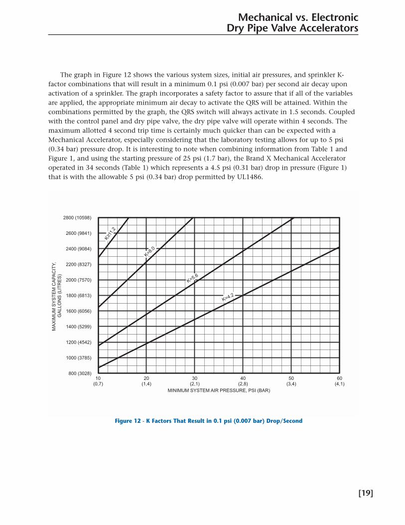
The graph in Figure 12 shows the various system sizes, initial air pressures, and sprinkler K-factor combinations that will result in a minimum 0.1 psi (0.007 bar) per second air decay uponactivation of a sprinkler. The graph incorporates a safety factor to assure that if all of the variablesare applied, the appropriate minimum air decay to activate the QRS will be attained. Within thecombinations permitted by the graph, the QRS switch will always activate in 1.5 seconds. Coupledwith the control panel and dry pipe valve, the dry pipe valve will operate within 4 seconds. Themaximum allotted 4 second trip time is certainly much quicker than can be expected with aMechanical Accelerator, especially considering that the laboratory testing allows for up to 5 psi(0.34 bar) pressure drop. It is interesting to note when combining information from Table 1 andFigure 1, and using the starting pressure of 25 psi (1.7 bar), the Brand X Mechanical Acceleratoroperated in 34 seconds (Table 1) which represents a 4.5 psi (0.31 bar) drop in pressure (Figure 1)that is with the allowable 5 psi (0.34 bar) drop permitted by UL1486.
Figure 12 - K Factors That Result in 0.1 psi (0.007 bar) Drop/Second

[20]
Mechanical vs. ElectronicDry Pipe Valve Accelerators
Summary
The simplicity and dependability of the QRS switch as a substitute for the mechanicalaccelerator are keys. The following list is a summary of some of the key benefits of the ElectricAccelerator:
* Facility Operator costs decrease due to less frequent maintenance issues.
* Fewer maintenance issues insure that the accelerators (critical to many systems) remain inservice.
* Faster operation improves the performance of larger dry systems.
* With no moving parts in the pressure sensing area (QRS switch), maintenance anddependability are improved dramatically.
* Without a restricted orifice, false trips due to temperature changes are eliminated.
* Without a restricted orifice, maintenance and resetting issues related to anti-flooding devicesand drain-back do not apply.
* Built-in low and high air pressure switches: small leakage will trigger supervisory alarm vs.the activation that might occur with a clogged restriction in a mechanical accelerator.
* Proven electronic technology used with electrically operated deluge and preaction systems.
* Consistent operating times improve water supply analysis and dry system performance.
* Accurate dry pipe valves trip times will assist in calculating dry pipe system performance.
* Insurance Risk assessment improvement due to dependability of service.

[21]
Mechanical vs. ElectronicDry Pipe Valve Accelerators
References:
1. Variables that Affect the Performance of Dry Pipe Systems - Tyco Fire and Building Products,Cranston RI - http://tyco-fireproducts.com/TFP_Gem/literature.php - Technical Reports andWhite Papers
2. Underwriters Laboratory - Northbrook, Illinois - UL 1486 Quick Opening Devices for DryPipe Valves for Fire Protection Service, April 29, 1997
3. National Fire Protection Association - Quincy, Massachusetts - NFPA 13 Installation ofSprinkler Systems, August 8, 2002.
4. National Fire Protection Association - Quincy, Massachusetts - NFPA 25 Standard for theInspection, Testing, and Maintenance of Water-Based Fire Protection Systems. January 31,2002

[22]
Mechanical vs. ElectronicDry Pipe Valve Accelerators
JAMES E GOLINVEAUXSenior Vice President, Research & Development
Mr. Golinveaux’s areas of interest include the research, design and applications of automatic fire
sprinklers as well as their history. His interest in the fire sprinkler industry was sparked by his father’s 27
years in the fire service.
Beginning as a designer in the early 1980’s and later as a design manager for a fire protection firm
in California, he applied local and national standards to develop working drawings for automatic fire
sprinkler systems. Mr. Golinveaux became active and continues his involvement today through his
membership on numerous committees such as the National Fire Protection Association (Member of
NFPA 13 Discharge & Installation), International Conference of Building Officials, Society of Fire
Protection Engineers and Southern Building Code Congress International. By 1991, Mr. Golinveaux’s
strong application knowledge of the automatic fire sprinkler industry afforded him the opportunity to
work on the East Coast as the Director of Technical Services for Central Sprinkler Company. Mr.
Golinveaux was responsible for the technical responses to worldwide production of automatic fire
sprinkler system components. He continued his involvement in the industry and represented Central
on many national committees including the National Fire Protection Research Foundation, Research
and Advisory Council on Fire Suppression Futures and Underwriters Laboratories Industry Advisory
Committee for automatic sprinklers. Mr. Golinveaux’s many talents and wealth of knowledge were
recognized by Central where he was Senior Vice President of Engineering and was directly responsible
for the Production Plant with over 600 employees, the Engineering/R & D, Quality Control and
Technical Services operations. Currently, Mr. Golinveaux is Senior Vice President of Research and
Development for Tyco Fire & Building Products, which represents Central, Gem and Star branded
products.
In addition to the support of the industry through his numerous committee memberships, Mr.
Golinveaux also contributes his time as a speaker for national education seminars sponsored by
organizations such as the Society of Fire Protection Engineers, Universities, Highly Protected Risk (HPR)
Insurance Companies, National Apprenticeship and Training, and Trade Associations as well as state and
local fire authorities. He has educated many on the latest sprinkler technology and its associated codes
and standards.
Mr. Golinveaux has authored “A Technical Analysis: The Use and Maintenance of Dry Type
Sprinklers”, “A Technical Analysis: Variables That Affect the Performance of Dry Pipe Systems”, and “A
Technical Analysis: Listings and Applications of Residential Sprinklers”. He has contributed to the NFPA
Fire Protection Handbook 19th Edition as well as the 2002 Automatic Sprinkler System Handbook. He is
also named on numerous U.S. Patents relating to automatic sprinklers.
About the Author

WORLDWIDE HEADQUARTERSTyco Fire & Building Products451 N. Cannon AvenueLansdale, PA 19446215-362-0700, 800-523-6512Fax 215-362-5385www.Tyco-Fire.com
UNITED STATESCentral Sprinkler Company451 N. Cannon AvenueLansdale, PA 19446215-362-0700, Fax 215-362-5385
Brea, CA: Tel: 714-993-6111, Fax 714-993-6043Decatur, GA: Tel: 404-243-7336, Fax 404-244-7375King of Prussia, PA: Tel: 610-239-9925, Fax 610-239-9936Jessup, MD: Tel: 301-604-7133, Fax 301-604-7138Carol Stream, IL: Tel: 630-871-7700, Fax 630-871-7464Coppell, TX: Tel: 972-745-0043, Fax 972-745-8594Kent, WA: Tel: 253-872-6030, Fax 253-872-6547Avon, MA: Tel: 508-583-8447, Fax 508-583-0034Pompano Beach, FL: Tel: 954-781-0866, Fax 954-781-1475Murray UT: Tel: 801-269-0688, Fax 801-269-0733Tigard, OR: Tel: 503-620-4203, Fax 503-620-3817Parma, OH: Tel: 216-265-0505, Fax 216-265-8354Kansas City, MO: Tel: 816-842-2424, Fax 816-842-4433
National Distribution FacilityPO Box 2806Lubbock, TX 79408-2806
Gem Sprinkler Company & Star Sprinkler Inc.7071 S. 13th Street, Ste. 103Oak Creek, WI 53154877-436-8926, Fax 877-866-9250
CANADARegional Headquarters12-16715 Yonge Street, Suite 316Newmarket, Ontario L3X 1X4705-422-0010, Fax: 705-422-1396
LATIN AMERICARegional HeadquartersSouth America, Central America & Caribbean1802 S.W. 2nd St.Pompano Beach, FL 33069954-781-0866, Fax 954-781-9330
Regional Headquarters - MexicoHamburgo 231A Piso 2Colonia JuarezMexico, D.F. 06600 Mexico525-55-2075766, Fax: 525-55-2077566
EUROPE & MIDDLE EASTRegional HeadquartersKopersteden 1, NL-7547 TJ EnschedeP.O. Box 198, 7500 ADEnschede, The Netherlands31-53-428-4444, Fax 31-53-428-3377
Stockport, UK: Tel: 44-161-477-1886, Fax 44-161-477-6729Paris Nord II, France: Tel: 33-1-48-178-727 , Fax 33-1-48-178-720Rodgau Germany: Tel: 49-6106-84455, Fax 49-6106-18177Coslada Madrid, Spain: Tel: 34-1-669-3906, Fax 34-1-669-2018Lørenskog, Norway: Tel: 47-67-91-77-00, Fax 47-67-91-77-15Lammhult, Sweden: Tel: 46-472-269-980, Fax 46-472-269-989Dublin, Ireland: Tel: 353-166-839-82, Fax 353-166-822-54Bolzano,Italy: Tel: 39-0471-252-091, Fax 39-0471-254-058Milano, Italy: Tel: 39-0293-548-736, Fax 39-0293-548-690Dubai, United Arab Emirates: Tel: 971-488-38689, Fax 971-488-38674Budapest, Hungary: Tel: 36-148-11-383, Fax 36-120-34-427Wels/Thalheim, Austria: Tel: 43-072-42-65-054, Fax 43-072-42-74-393
ASIARegional HeadquartersNo.45 Tuas Avenue 9,Singapore 639189
Central Sprinkler CompanySingapore: 65- 6743-3212, Fax 65-6743-9181Shanghai, China: 86-21-5868-3300, Fax 86-21-5868-1160Beijing, China: 86-10-6515-6191, Fax 86-10-6515-6157Chengdu, China: 86-28-689-9440, Fax 86-28-666-2538
Gem Sprinkler Company & Star Sprinkler Inc.Singapore: 65-6861-1655, Fax 65-6861-1312Kuala Lumpur, Malaysia: 60-3-8024-6773, Fax 60-3-8024-2180Hong Kong: 852-2595-0686, Fax 852-2505-5826
Printed in USA / RPI / 4.04 / 3M / ©2004 Tyco Fire Products. All rights reserved.
Tyco is either a registered trademark or trademark of Tyco and/or its affiliates in the United States and inother countries. All other brand names, product names, or trademarks belong to their respective holders.