question 3 – transfer functions - rensselaer...
TRANSCRIPT

ENGR-4300 Test 2 Fall 2007
ENGR-4300Fall 2007
Test 2
Name _______SOLUTION__________
Section 1(MR) 2(TF)(circle one)
Question I (20 points) ___________
Question II (20 points) ___________
Question III (15 points) ___________
Question IV (20 points) ___________
Question V (25 points) ___________
Total (100 points): ______________
On all questions: SHOW ALL WORK. BEGIN WITH FORMULAS, THEN SUBSTITUTE VALUES AND UNITS. No credit will be given for numbers that appear without justification.
1 of 14

ENGR-4300 Test 2 Fall 2007
Question I – Bridges and Damped Sinusoids (20 points)
One of the most powerful tools we have as engineers is MATLAB, which is especially useful when one does a Simulink model of a system. (The following is provided for completeness. You do not need to know how to work with Simulink to do this problem.) A Simulink model for a cantilever beam is shown below.
Velocity
Position
k/m
Normalized Spring Constant
b/m
Normalized Damping
1s
Integrator1
1s
IntegratorAdd
Acceleration
The blocks marked Acceleration, Velocity and Position are ‘scopes that provide data on the given parameter as a function of time. In no particular order, these three plots follow for a particular set of values for k, b, and m (the spring constant, the damping constant and the mass, respectively).
0 0.1 0.2 0.3 0.4 0.5 0.6 0.7 0.8 0.9 1-1500
-1000
-500
0
500
1000
Time 0 0.1 0.2 0.3 0.4 0.5 0.6 0.7 0.8 0.9 1
-1.5
-1
-0.5
0
0.5
1
1.5
2
Time
0 0.1 0.2 0.3 0.4 0.5 0.6 0.7 0.8 0.9 1-50
-40
-30
-20
-10
0
10
20
30
40
Time
2 of 14
C
BA
T=0.25s
X0=2
X1=0.164

ENGR-4300 Test 2 Fall 2007
1) (3pt) Identify which plot is position, which is velocity and which is acceleration. From the plots, what are the initial position, velocity and acceleration? Assume SI units (position in meters, velocity in meters per second, acceleration in meters per second squared).
A: __ACCELERATION______ B: __POSITION__________ C: __VELOCITY________
Initial position: __2m_______ Initial velocity: __0m/s______ Initial acceleration: __1250m/s 2 __
2) (6pt) Find the frequency f, the period T, and the damping constant and then evaluate the mathematical expression for each of the three functions – position, velocity and acceleration of the beam. Generically, these expressions are in the form where Fo, , and
are constants.
T = 0.25s f = 1/T = 4Hz = 2f = 25 rad/s
x(t) = 2e-2.5t cos(25t + 0) m
v(t) = 50e-2.5t cos(25t + /2) m/s
a(t) = 1250e-2.5t cos(25t + ) m/s2
3) (3pt) From these three expressions, determine the mass m, the damping coefficient b and the spring constant k for the cantilever beam being analyzed.
Grading on this should be based more on the approach than the actual answer; partial credit given for any relevant equations or explanations.
3 of 14

ENGR-4300 Test 2 Fall 2007
Question I – Bridges and Damped Sinusoids (continued)
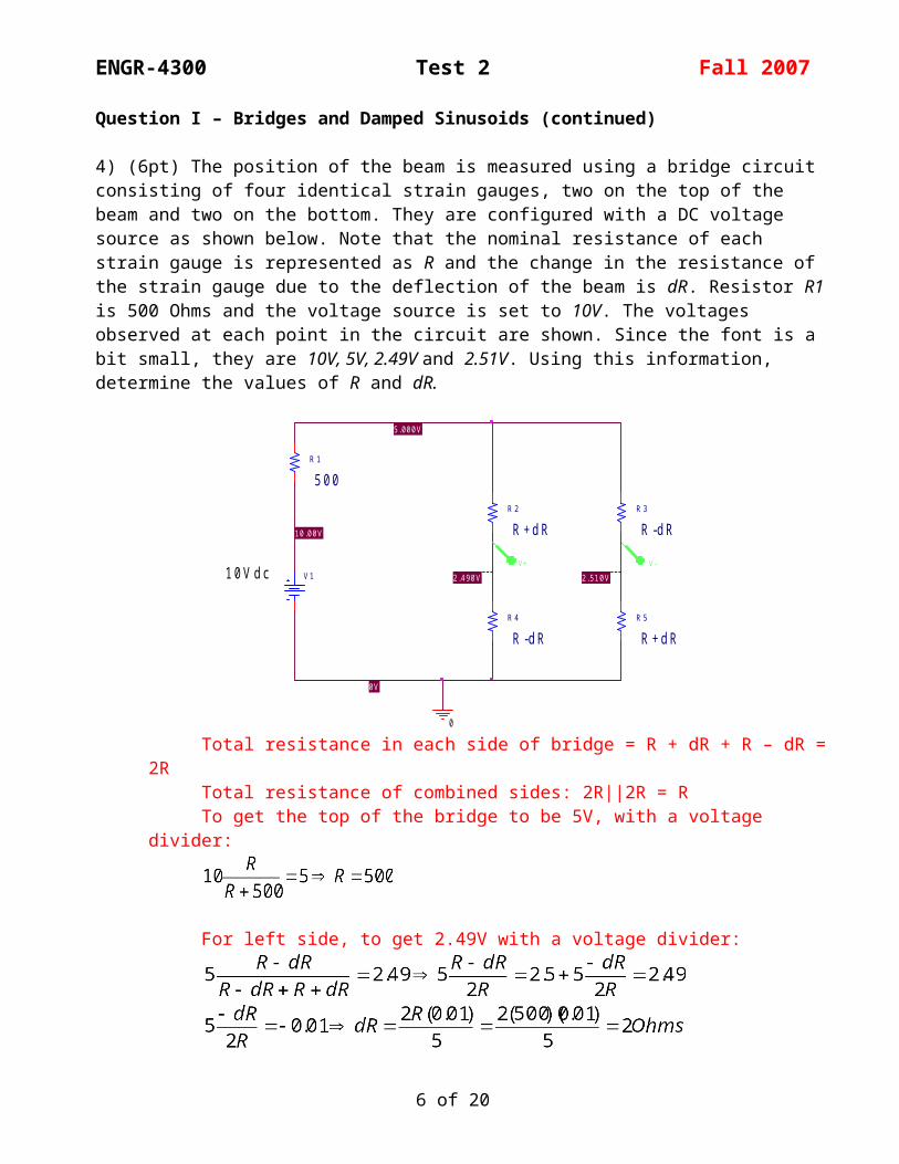
4) (6pt) The position of the beam is measured using a bridge circuit consisting of four identical strain gauges, two on the top of the beam and two on the bottom. They are configured with a DC voltage source as shown below. Note that the nominal resistance of each strain gauge is represented as R and the change in the resistance of the strain gauge due to the deflection of the beam is dR. Resistor R1 is 500 Ohms and the voltage source is set to 10V. The voltages observed at each point in the circuit are shown. Since the font is a bit small, they are 10V, 5V, 2.49V and 2.51V. Using this information, determine the values of R and dR.
2 . 51 0 V
0
V-
R 5
R+dRR 4
R-dR
2 . 49 0 VV 110Vdc
<D o c > <R e v C o d e >
<Tit le >
A
1 1Tu e s d a y , O c t o b e r 1 6 , 20 0 7
Tit le
S ize D o c u m e n t N u m b e r R ev
D a t e : S h e e t o f
V+
5 . 00 0 V
0V
1 0 . 0 0 V
R 1
500
R 2
R+dRR 3
R-dR
Total resistance in each side of bridge = R + dR + R – dR = 2RTotal resistance of combined sides: 2R||2R = RTo get the top of the bridge to be 5V, with a voltage divider:
For left side, to get 2.49V with a voltage divider:
4 of 14

ENGR-4300 Test 2 Fall 2007
Question I – Bridges and Damped Sinusoids (continued)
5) (2pt) Which of the following can be modeled as cantilever beams? Circle the pictures of the appropriate examples and also show where the cantilever is located. ALL ARE CANTILEVERS
5 of 14
ENGR-4300 Test 2 Fall 2007
6 of 14

ENGR-4300 Test 2 Fall 2007
Question II – Thevenin Equivalents (20 points)
2 0 V d c
0
B
3 k
A
5 0 0
7 k
1 k
6 k1 . 5k
V t h
0
A
B
R t h
1) (5pt) Find the Thevenin equivalent voltage with respect to A and B for the circuit shown above left.
2) (5pt) Find the Thevenin equivalent resistance with respect to A and B for the circuit shown above left.
3) (3pt) What value load resistance added between A and B will have the largest possible voltage across it and how much power will be dissipated in the resistor?
Max voltage when Rload = ohms (open circuit)
P = VxI = 4V x 0A = 0W
4) (3pt) What value load resistance added between A and B will have the largest possible current through it and how much power will be dissipated in the resistor?
Max current when Rload = 0 ohms (short circuit)
P = VxI = 0V x (4/1.6k)A = 0W
5) (4pt) If the DC voltage source is replaced with an AC source and a 1 F capacitor is placed across A and B, what is the corner frequency (in radians/s) of the resultant RC filter? Is it a HPF or a LPF?
= 1/(RC) = 1/(1.6k x 1uF) = 1/1.6ms = 625 rad/s LPF
7 of 14

ENGR-4300 Test 2 Fall 2007
Question III – Op-Amp Applications (15 points)
2 k
2 k
8 k
V 4
Vo u t
V 3
0
3 k
1 k
0
V 1
0
8 k
0 1 0 0 k
0
U 3
+
-
O U T
U 1
+
-
O U T
U 2
+
-
O U T
V 2
5 0 0
5 0 0
Assume that 9 Volt power supplies have been properly connected to all three op-amps in the circuit above.
1) (3pt) The circuit has 3 op-amps labeled as U1, U2, and U3. State what the op-amp circuit is for each. Choices are: 1. Follower/Buffer, 2. Inverting Amp, 3. Non-inverting Amp, 4. Differentiator, 5. Integrator, 6. Adding (Mixing) Amp, 7. Difference (Differential) Amp.
U1 Circuit: INVERTING AMP U2 Circuit: _FOLLOWER _ U3 Circuit: _DIFFERENCE AMP_
2) (4pt) Determine the voltage, relative to ground, at points V3 and V4 as functions of V1 and V2.
a) Voltage at point V3:
b) Voltage at point V4:
8 of 14

ENGR-4300 Test 2 Fall 2007
Question III – Op-Amp Applications (continued)
3) (2pt) Determine the output voltage, Vout, as a function of V3 and V4.
4) (2pt) Now find Vout as a function of V1 and V2.
5) (4pt) If V1 = +2 Volts, how large can V2 become before the output will no longer match the result given by your answer in 4)?.
9 of 14

V1
FREQ =VAMPL =VOFF =
V2
FREQ =VAMPL =VOFF = U1
+3
-2
V+7
V-4
OUT6
OS11
OS25
R1
R2
R3
Rload
0
0
0
0
0
0
Vneg
-9Vdc
Vpos
9Vdc
Vout
ENGR-4300 Test 2 Fall 2007
Question IV – Op-Amp Analysis (20 points)
Above is a Capture schematic of an op-amp circuit that you should recognize. Assume the op-amp is ideal.
1) (2pt) What type of circuit is it?
Adder
2) (2pt) When assuming that the op-amp is ideal, what are the two golden rules to analyze this circuit?
VA=VB or V+=V-, IA=IB=0 or I-=I+=0
3) (4pt) Use these rules to derive an expression for Vout in terms of R1, R2, R3, V1 and V2. (Hint: you may exclude Rload.) Redraw the circuit (Remove the op-amp and draw two circuits: one for the + and one for the – input terminals of the op-amp, draw currents I1, I2, and I3 through R1, R2, and R3 respectively, on the circuit).
0
10 of 14
V-
R 1 R 3
R 2
Vout
V2
V1
I1
I2
I3
V+

ENGR-4300 Test 2 Fall 2007
Question IV – Op-Amp Analysis (continued)
4) (4pt) Write equations for the two circuits (use the current relationship).
5) (4pt) Simplify using the golden rules and solve for Vout.
6) (4pt) If V1 = 0.2 V, V2 = 0.3V, R1 = 3kΩ, R2 = 3kΩ, and R3 = 12kΩ, what is the value of Vout in volts? (Show your work.)
Vout = -2V
11 of 14

ENGR-4300 Test 2 Fall 2007
Question V – Op-Amp Integrators and Differentiators (25 points)
V 1
F R E Q =V A M P L =V O F F =
R 1
1 0 k
U 1
u A 7 41
+3
-2
V+
7V
-4
O U T6
O S 11
O S 25 R lo a d
2 k
V n e g-9 V d c
V p o s9 V d c
0
0
0
0
0
Vout
C 1
0 . 1 u F
Assume the op-amp in the circuit above is ideal.
1) (1pt) Above is a Capture schematic of an op-amp circuit that you should recognize. What type of circuit is it?
Ideal integrator
2) (4pt) For this circuit the input is sinusoidal. What is H(jω), the transfer function, for this circuit? H(jω) = Vout/V1. You must use the component values; don’t leave the answer in terms of R1 or C1. Simplify your answer.
3) (4pt) If a 1k resistor is added in parallel with C1, what is the corner frequency in Hertz?
4) (1pt) If the input frequency is 10 kHz, will it operate as it should?
Works as an integrator above ωc so it will operate correctly
12 of 14

ENGR-4300 Test 2 Fall 2007
Question V – Op-Amp Integrators and Differentiators (continued)
V 1
F R E Q =V A M P L =V O F F =
C 1
5 n F
R 1
2 0 k
U 1
u A 7 4 1
+3
-2
V+
7V
-4
O U T6
O S 11
O S 25
R 2
1 k
R lo a d2 k
V n e g-9 V d c
V p o s9 V d c
0
0
0
0
0
Vout
Assume that the input is sinusoidal and we want to find H(jω), the transfer function, for this circuit. We know that when the non-inverting terminal of an op amp circuit is grounded, H(jω) = -Zf/Zin.
5) (1pt) Find Zf and substitute values for components.
Zf = R2 = 1k, Zf = 1k
6) (4pt) Find Zin. Substitute values for the components. Simplify your answer.
7) (4pt) Using 5) and 6) determine the transfer function, H(jω), for the circuit. Substitute component values. Simplify your answer.
13 of 14

ENGR-4300 Test 2 Fall 2007
Question V – Op-Amp Integrators and Differentiators (continued)
8) (3pt) At high frequency this circuit in 5) acts like a __________________.Fill in the blank using one of the following: a) Inverting Amplifier, b) Non-inverting Amplifier, c) Differential Amplifier, d) Adder, e) Integrator, f) Differentiator, g) none of a thru e.
Differentiator(Also may accept g) none of a through e because the transfer function approaches infinity and won’t be a useful differentiator)
9) (3pt) Now assume that Vin is a 0.2V DC source. What is Vout?
DC input is zero frequency. The transfer function at zero frequency (ω approaches zero) is H(jω) = -0.05. The phase is π, so the signal is inverted.
The signal is inverted so Vout=-0.01V
Also can realize that the capacitor behaves like an open circuit at low frequency. The circuit turns into an inverting amplifier.
Vout = -R2/R1(Vin) = -(1k/20k)(0.2) = -0.01V
14 of 14