quantum systems - arxiv · quantum systems ze-liang xiang department of physics and state key...
TRANSCRIPT

Hybrid quantum circuits: Superconducting circuits interacting with otherquantum systems
Ze-Liang Xiang∗
Department of Physics and State Key Laboratory of Surface Physics, Fudan University, Shanghai 200433,China andAdvanced Science Institute, RIKEN, Saitama 351-0198, Japan,
Sahel Ashhab†
Advanced Science Institute, RIKEN, Saitama 351-0198, Japan, andDepartment of Physics, The University of Michigan, Ann Arbor, Michigan 48109, USA
J. Q. You‡
Department of Physics and State Key Laboratory of Surface Physics, Fudan University, Shanghai 200433,China,Beijing Computational Science Research Center, Beijing 100084, China, andAdvanced Science Institute, RIKEN, Saitama 351-0198, Japan
Franco Nori§
Advanced Science Institute, RIKEN, Saitama 351-0198, Japan, andDepartment of Physics, The University of Michigan, Ann Arbor, Michigan 48109, USA
(Dated: April 11, 2013)
Hybrid quantum circuits combine two or more physical systems, with the goal of harnessing theadvantages and strengths of the different systems in order to better explore new phenomena andpotentially bring about novel quantum technologies. This article presents a brief overview ofthe progress achieved so far in the field of hybrid circuits involving atoms, spins and solid-statedevices (including superconducting and nanomechanical systems). How these circuits combineelements from atomic physics, quantum optics, condensed matter physics, and nanoscience isdiscussed, and different possible approaches for integrating various systems into a single circuitare presented. In particular, hybrid quantum circuits can be fabricated on a chip, facilitating theirfuture scalability, which is crucial for building future quantum technologies, including quantumdetectors, simulators, and computers.
PACS numbers: 85.25.-j, 42.50.Pq, 03.67.Lx, 76.30.Mi
Contents
I. Introduction 2
II. Elements in hybrid quantum circuits 3
A. Atoms 3
B. Spins 4
C. Superconducting qubits 6
D. Cavities and resonators 6
1. Optical cavities 8
2. Superconducting resonators 8
3. Nanomechanical resonators 8
III. Cavity quantum electrodynamics 9
A. Atoms coupled to cavities 9
B. Spins coupled to cavities 9
C. Superconducting qubits coupled to resonators 10
∗Electronic address: [email protected]†Electronic address: [email protected]‡Electronic address: [email protected]§Electronic address: [email protected]
IV. Theoretical principles and proposals for hybridsystems integrating atoms or spins insuperconducting circuits 12A. Atoms or spins coupled to superconducting
resonators (without superconducting qubits) 12B. Atoms or spins coupled to superconducting
resonators and qubits 131. Direct coupling 142. Indirect coupling 14
C. Direct-coupling hybrid circuits 15D. Indirect-coupling hybrid circuits 17
1. Atomic hybrid quantum circuits 172. Spin hybrid quantum circuits 20
V. Experimental realization of hybrid systems withspins and superconducting circuits 21A. Direct-coupling hybrid circuit with nitrogen-vacancy
centers and a flux qubit 22B. Spins coupled to superconducting resonators
(without qubits) 22C. Indirect-coupling hybrid circuits with
nitrogen-vacancy centers and a transmon qubit 23
VI. Hybrid quantum circuits with nanomechanicalresonators 25A. Coupling mechanisms 25
arX
iv:1
204.
2137
v5 [
quan
t-ph
] 1
0 A
pr 2
013
2
1. Capacitive coupling 252. Magnetic flux coupling 253. Electromotive coupling 254. Coupling dynamics 26
B. Applications 26
VII. Other hybrid quantum circuits 27A. Hybrid quantum circuits with microscopic defects 27B. Hybrid quantum circuits with topological qubits 27C. Hybrid quantum circuits for converting optical
photons to microwave photons 28
VIII. Discussion and conclusion 28
Acknowledgements 29
References 29
I. INTRODUCTION
The field of quantum information processing is at-tracting considerable interest, and scientists in a vari-ety of disciplines have devoted intense effort to the re-alization of quantum information principles, technolo-gies, and algorithms (Bennett and DiVincenzo, 2000; Di-Vincenzo, 2000; Georgescu and Nori, 2012; Nielsen andChuang, 2000; Schleich and Walther, 2008; Stolze andSuter, 2008). The most advanced experimental demon-strations of controllable quantum coherent systems in-clude trapped ions and atoms (Blatt and Wineland, 2008;Bloch, 2008; Buluta et al., 2011), spins (Buluta et al.,2011; Hanson and Awschalom, 2008a; Hanson et al.,2007), and superconducting circuits (Buluta et al., 2011;Clarke and Wilhelm, 2008; Makhlin et al., 2001; Wendinand Shumeiko, 2007; You and Nori, 2005, 2011; Zagoskin,2011).
The properties of atoms have been studied extensivelyover the past century. Atoms have stable energy lev-els that can be used to represent the different states ofqubits. In addition, the coherence times of isolated atomsare long because of their weak interaction with the sur-rounding environment (Blatt and Wineland, 2008; Lukin,2003).
Spins are another promising candidate for future quan-tum technologies (Hanson and Awschalom, 2008a). Im-purity spins can behave as qubits and can be used tostore or process quantum information. For example,phosphorous impurities in silicon (Kane, 1998; Morelloet al., 2010) and nitrogen-vacancy (NV) color centers indiamond (Doherty et al., 2012; Wrachtrup and Jelezko,2006) possess good coherence properties, which allowlong storage times. Furthermore, rapid progress has beenmade with quantum dots (Hanson et al., 2007; Loss andDiVincenzo, 1998; Zwanenburg et al., 2013), which canbe fabricated on a chip and controlled relatively easilyusing electric signals.
Remarkable progress has also been made on other sys-tems, such as superconducting (SC) circuits. These SCcircuits promise good scalability (Ashhab et al., 2008;Galiautdinov et al., 2012; Harris, 2012; Helmer et al.,
2009) and allow robust control, storage and readout dueto their strong interaction with external fields.
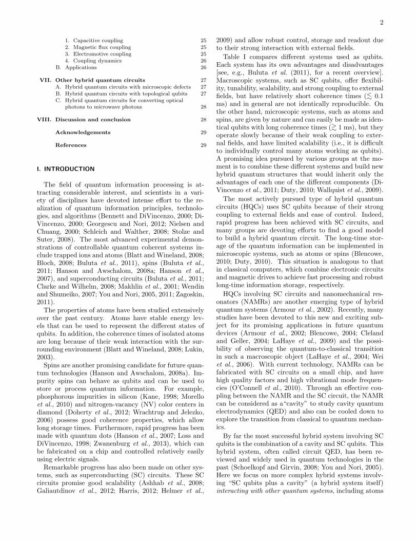
Table I compares different systems used as qubits.Each system has its own advantages and disadvantages[see, e.g., Buluta et al. (2011), for a recent overview].Macroscopic systems, such as SC qubits, offer flexibil-ity, tunability, scalability, and strong coupling to externalfields, but have relatively short coherence times (<∼ 0.1ms) and in general are not identically reproducible. Onthe other hand, microscopic systems, such as atoms andspins, are given by nature and can easily be made as iden-tical qubits with long coherence times (>∼ 1 ms), but theyoperate slowly because of their weak coupling to exter-nal fields, and have limited scalability (i.e., it is difficultto individually control many atoms working as qubits).A promising idea pursued by various groups at the mo-ment is to combine these different systems and build newhybrid quantum structures that would inherit only theadvantages of each one of the different components (Di-Vincenzo et al., 2011; Duty, 2010; Wallquist et al., 2009).
The most actively pursued type of hybrid quantumcircuits (HQCs) uses SC qubits because of their strongcoupling to external fields and ease of control. Indeed,rapid progress has been achieved with SC circuits, andmany groups are devoting efforts to find a good modelto build a hybrid quantum circuit. The long-time stor-age of the quantum information can be implemented inmicroscopic systems, such as atoms or spins (Blencowe,2010; Duty, 2010). This situation is analogous to thatin classical computers, which combine electronic circuitsand magnetic drives to achieve fast processing and robustlong-time information storage, respectively.
HQCs involving SC circuits and nanomechanical res-onators (NAMRs) are another emerging type of hybridquantum systems (Armour et al., 2002). Recently, manystudies have been devoted to this new and exciting sub-ject for its promising applications in future quantumdevices (Armour et al., 2002; Blencowe, 2004; Clelandand Geller, 2004; LaHaye et al., 2009) and the possi-bility of observing the quantum-to-classical transitionin such a macroscopic object (LaHaye et al., 2004; Weiet al., 2006). With current technology, NAMRs can befabricated with SC circuits on a small chip, and havehigh quality factors and high vibrational mode frequen-cies (O’Connell et al., 2010). Through an effective cou-pling between the NAMR and the SC circuit, the NAMRcan be considered as a“cavity” to study cavity quantumelectrodynamics (QED) and also can be cooled down toexplore the transition from classical to quantum mechan-ics.
By far the most successful hybrid system involving SCqubits is the combination of a cavity and SC qubits. Thishybrid system, often called circuit QED, has been re-viewed and widely used in quantum technologies in thepast (Schoelkopf and Girvin, 2008; You and Nori, 2005).Here we focus on more complex hybrid systems involv-ing “SC qubits plus a cavity” (a hybrid system itself)interacting with other quantum systems, including atoms
3
TABLE I. Comparison between different systems used as qubits.
Atom, molecule, ion Electron spin Nuclear spin Superconducting qubit
Size ∼ 10−10 m ∼ 10−10 m (impurities)∼ 10−8 m (quantum dot)a
< 10−10 ma ∼ 10−6 m
Energy gap 105–106 GHz,∼ GHz (Rydberg atoms)
1–10 GHz 1–10 MHz 1–20 GHz
Frequency range Optical, microwave Microwave Microwave Microwave
Operatingtemperature
nK to µK ∼ 100 mK (quantum dot)room temp. (NV center)
∼ mK ∼ 10 mK
Single-qubit gateoperation time τ1
∼ µs (atom)∼ 50 ps (ion)
∼ 10 ns > 10 µs ∼ 1 ns
Two-qubit gateoperation time τ2
∼ µs (atom)∼ 100 µs (ion)
∼ 0.2 ns ∼ 10 ms ∼ 10–50 ns
Coherence time T2 ms to s ms to s ∼ s ∼ 10–100 µs
T2/τ1 10–104 105–108 106 104–105
Coupling type Electric or magnetic Magnetic or electric Magnetic Electric or magnetic
Coupling strengthwith the cavity
< kHz (B-field),∼ 10 kHz (E-field),∼ 10 MHz (Rydberg atoms)
∼ 100 Hz (impurities)> MHz (quantum dot)
∼ 0.1 Hz ∼ 0.1–1 GHz
a Regarding the size of the electron and nuclear spins, as theseare carried by pointlike particles, the size might be <∼ 10−15 m.However, the more relevant quantity in this context is the sizecontributing to the interaction. In particular, the interaction istypically determined by the overlap integral of the coupled objects,and therefore the relevant size is the spatial extension of the wave-function.
(both natural and artificial) as well as ions and variousother quantum systems. Namely, the hybrid circuits wewill be focusing on here are composed of various typesof quantum systems interacting with a (hybrid) circuitQED system.
In this review, we first overview different basic ele-ments needed to build HQCs, and then we highlight theprogress achieved so far integrating these systems.
II. ELEMENTS IN HYBRID QUANTUM CIRCUITS
A. Atoms
Atomic systems (including neutral atoms, polarmolecules, and ions) have been studied for a long time,and are promising systems for future quantum technolo-gies.
Because of the weak interaction with the environ-ment, atomic systems can achieve long coherence times,which is useful for storing quantum information. In gen-eral, optical pumping and cooling, electromagnetic radia-tion, and laser-induced fluorescence are utilized to initial-ize, manipulate, and measure the qubit encoded in theatomic levels (Lukin, 2003). Recently, much progress was
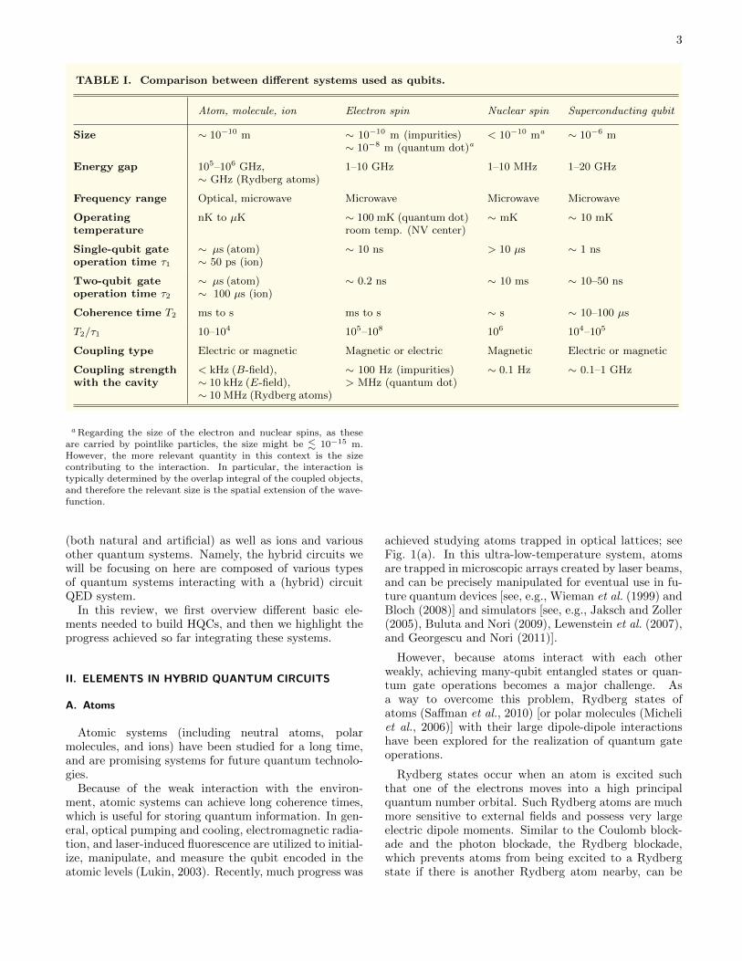
achieved studying atoms trapped in optical lattices; seeFig. 1(a). In this ultra-low-temperature system, atomsare trapped in microscopic arrays created by laser beams,and can be precisely manipulated for eventual use in fu-ture quantum devices [see, e.g., Wieman et al. (1999) andBloch (2008)] and simulators [see, e.g., Jaksch and Zoller(2005), Buluta and Nori (2009), Lewenstein et al. (2007),and Georgescu and Nori (2011)].
However, because atoms interact with each otherweakly, achieving many-qubit entangled states or quan-tum gate operations becomes a major challenge. Asa way to overcome this problem, Rydberg states ofatoms (Saffman et al., 2010) [or polar molecules (Micheliet al., 2006)] with their large dipole-dipole interactionshave been explored for the realization of quantum gateoperations.
Rydberg states occur when an atom is excited suchthat one of the electrons moves into a high principalquantum number orbital. Such Rydberg atoms are muchmore sensitive to external fields and possess very largeelectric dipole moments. Similar to the Coulomb block-ade and the photon blockade, the Rydberg blockade,which prevents atoms from being excited to a Rydbergstate if there is another Rydberg atom nearby, can be

4
(b)(a)
(d)
N
V
(c)Quantum dots
Gate
2DEG
GaAs
AlxGa
1-xAs
Charge sensor
Trapped atoms
Optical potential
Trapped ions
Substrate with
trap fields
Carbon
FIG. 1 (color online). Different types of qubits: (a) atoms trapped in an optical lattice; (b) a planar trap of ions; (c) anelectrostatically-defined quantum dot; and (d) a nitrogen-vacancy (NV) center in diamond. (a) and (b) are adapted fromBuluta et al. (2011).
used to entangle two atoms located in two separate op-tical dipole traps and implement effective two-qubit gateoperations (Saffman et al., 2010).
Ions are another prospective type of qubits with longcoherence times (Blatt and Wineland, 2008; Cirac andZoller, 2000). Because they are charged, interactionsamong ions via Coulomb repulsion are much strongerthan those among atoms. This property facilitates therealization of two- or multiqubit operations. Ions canalso be cooled by laser beams and trapped by electri-cal or magnetic fields, and they can be manipulated withhigh precision, see Fig. 1(b). Generally, hyperfine or Zee-man sublevels, the ground and excited states of an op-tical transition, and the collective motion of ions can beused to encode quantum information with long lifetimes> 20 s, > 1 s, and < 100 ms, respectively. The single-qubit gate time of trapped ions is around 50 ps, whilethe two-qubit gate time is around hundreds of microsec-onds (Buluta et al., 2011). The manipulation of ions canbe achieved using the same methods used for atoms.
In atomic systems, the coherence times are very long.However, compared to other systems, initialization, op-eration and measurement times are also very long. Thus,combining an atomic system (with long coherence times)with another system that allows fast operations hasemerged as a possible way to construct novel devices ben-
efiting from the advantages of two seemingly differentsystems.
B. Spins
Spins can also serve as qubits and store or processquantum information (Hanson and Awschalom, 2008a).In general, two kinds of spins are used in quantum com-putation: electron spin and nuclear spin. Both types caninteract with the electric or magnetic fields of a photon.
One can trap atomic gases and utilize electron spinsto store quantum information. However, the techniquesof trapping and cooling are rather complicated. Alter-natively, by integrating dopants into a solid-state hostmaterial, large arrays of spin qubits can more easily beassembled in experiment.
Spins in solids generally fall into two classes: quan-tum dots and atomic impurities. Quantum dots are smallnanostructures where electrons are trapped in a potentialwell and have discrete energy levels (Hanson et al., 2007;Loss and DiVincenzo, 1998; Zwanenburg et al., 2013); seeFig. 1(c). These come in several forms. One is electro-statically defined quantum dots, where the distributionof electrons is controlled by voltages on lithographicallyfabricated metallic gates. Another form is self-assembled
5
quantum dots, where electrons are confined by the artifi-cial potential produced by a semiconductor growth pro-cess. In both types of quantum dots, by employing elec-trical or optical control, the manipulation, storage andreadout of the qubit have been demonstrated in exper-iment, with typical gate times ∼ 200 ps (Hanson andAwschalom, 2008a; Petta et al., 2005). As reported byNowack et al. (2007), the coupling strength between theelectric field and a single electron spin in a quantum dotcan reach ∼ 5 MHz, which is much larger than the cou-pling strength (∼ 100 Hz) between the external magneticfield and the electron spin in an impurity (Schoelkopf andGirvin, 2008). However, the interaction between the spinand its surrounding spin bath (mainly nuclear spins) hasso far limited coherence times to hundreds of microsec-onds or less (Bluhm et al., 2011).
Atomic impurities, such as phosphorus in sili-con (Kane, 1998; Morello et al., 2010; Pla et al., 2012),Er3+ ions in Y2SiO5 crystal (Guillot-Noel et al., 2006),and NV color centers in diamond (Doherty et al., 2012;Wrachtrup and Jelezko, 2006), can be conveniently inte-grated in solid-state devices and can have nuclear spins,electron spins, or both. Phosphorus impurities in siliconinvolve both electron and nuclear spins, and they possessexcellent coherence properties [both have spin coherencetimes T2 > 1 s (Morton et al., 2008; Simmons et al., 2011;Steger et al., 2012; Tyryshkin et al., 2012)]. Gate timesare on the order of 1 ns. Using microwave and radio-frequency pulses, spins can implement quantum infor-mation processing, especially storage, in a conventionalsemiconductor material. Also, these spins can be con-trolled by strain (Weiler et al., 2011) or via the Starkshift (Bradbury et al., 2006). Electron spins of Er3+ ionsdoped in a crystal also have long coherence times (> 1ms). Either optical or microwave photon states can bemapped into spin states of Er3+ ions by different energy-level transitions (Bushev et al., 2011; Guillot-Noel et al.,2006). Thus, Er3+ ions are a good candidate for use as aquantum interface between microwave and optical pho-tons.
An NV center in diamond consists of a substitutionalnitrogen (N) atom replacing a carbon atom and neighbor-ing one vacancy (V). In such centers, both electron andnuclear spins can be used in quantum technologies andalso exhibit long coherence times (∼ 1 ms for the electronspin and > 1 s for the nuclear spin; the single-qubit gatetime is ∼ 10 ns for electron spins and > 10 µs for nuclearspins) in a wide temperature range, even at room tem-perature (Balasubramanian et al., 2009; Gaebel et al.,2006; Hanson et al., 2008b; Maurer et al., 2012; Neu-mann et al., 2010; van der Sar et al., 2012). Importantly,these NV centers can be used to detect weak magneticfields (Maze et al., 2008; Taylor et al., 2008) and electricfields (Dolde et al., 2011) at room temperature, insteadof using low-temperature sensors.
The electronic ground state of the NV center is a spin-1 triplet, |ms〉 with ms = 0,±1. In the absence of amagnetic field, the ms = ±1 sublevel is two-fold degen-
erate and the resonance transition frequency between thems = 0 and ms = ±1 sublevels is 2.87 GHz, which nicelymatches the microwave frequency regime of SC qubits.This zero-field splitting in the NV center is caused by thereduction of the spin’s rotation symmetry in the crystal.In the presence of a magnetic field, the ms = ±1 sub-level is split into two levels, which makes it possible toaddress these two levels individually. NV centers alsopossess transitions from the electronic ground state toan excited electronic state, and the corresponding transi-tion frequency is in the optical regime. These transitionscan be used for the initialization and readout of the quan-tum state. Therefore, by using both laser and microwavefields, one can implement the manipulation, storage, andreadout of the quantum information encoded in the dif-ferent sublevels (Buckley et al., 2010; Fuchs et al., 2009;Jelezko et al., 2004). Furthermore, coherence times canbe enhanced if one applies appropriate sequences of laserpulses and microwave fields (de Lange et al., 2010; Fuchset al., 2010; Naydenov et al., 2011), or transfers the quan-tum information from the electron spins to nearby nu-clear spins by using the hyperfine interaction (Childresset al., 2006; Fuchs et al., 2011; Jiang et al., 2008). Suchinteractions also allow the implementation of few-qubitquantum registers (Dutt et al., 2007; Neumann et al.,2008).
In addition, because NV centers couple to both opticaland microwave fields, they can also be used as a quantuminterface between optical and solid-state systems. Thisprovides a promising platform to study novel quantumphenomena based on NV centers separated by long dis-tances. For instance, quantum interference of two polar-ized optical photons produced by NV centers in two sepa-rate diamond samples (Sipahigil et al., 2012) [or two sep-arate NV centers in the same diamond sample (Bernienet al., 2012)] and quantum entanglement between a polar-ized optical photon and a NV center qubit (Togan et al.,2010) have recently been realized in experiment.
Group-V endohedral fullerenes, consisting of a group-V atom (e.g., nitrogen) trapped inside a fullerene cage,are another spin system (Harneit, 2002) that might beintegrated in solid-state systems. Group-V endohedralfullerenes exhibit extraordinarily long spin relaxationtimes (Morton et al., 2007) (∼ 1 s at 4 K) due to the ex-istence of the fullerene cage, which protects the enclosedspin from fluctuating perturbations in various host envi-ronments. The molecule N@C60, which has electron spinS = 3/2 coupled to the 14N nuclear spin I = 1 via anisotropic hyperfine interaction, is a major member of thegroup-V endohedral fullerenes. By utilizing the technol-ogy of electron-spin resonance (or nuclear magnetic res-onance), quantum operations and readout of the qubitsencoded in the electron (or nuclear) spins of the nitrogenatoms of the molecule N@C60 could be achieved.
Spin systems have similar or even longer coherencetimes than atomic systems. However, weak coupling toexternal fields leads to difficulties in the implementationof quantum gate operations. Solid-state systems, such as
6
SC circuits, are an attractive platform for that purpose,as discussed in the next section.
C. Superconducting qubits
SC qubit circuits based on Josephson junctions aremacroscopic circuits, and they operate at temperaturesof tens of mK. Although not microscopic in size, theycan still behave quantum mechanically, allowing the ob-servation of quantum coherence on a macroscopic scale.Compared to normal harmonic oscillators formed by LCcircuits, in SC qubits the energy-level separation becomesnonuniform by introducing a nonlinearity via Josephsonjunctions. This property allows one to encode a qubitin the lowest two levels of a SC circuit for implementingquantum computing and simulation (Buluta and Nori,2009; Burkard et al., 2004; Clarke and Wilhelm, 2008;Georgescu and Nori, 2011; Makhlin et al., 2001; Nationet al., 2012; Wendin and Shumeiko, 2007; You and Nori,2005, 2011; Zagoskin, 2011). These circuits have two im-portant parameters: the Josephson coupling energy EJ
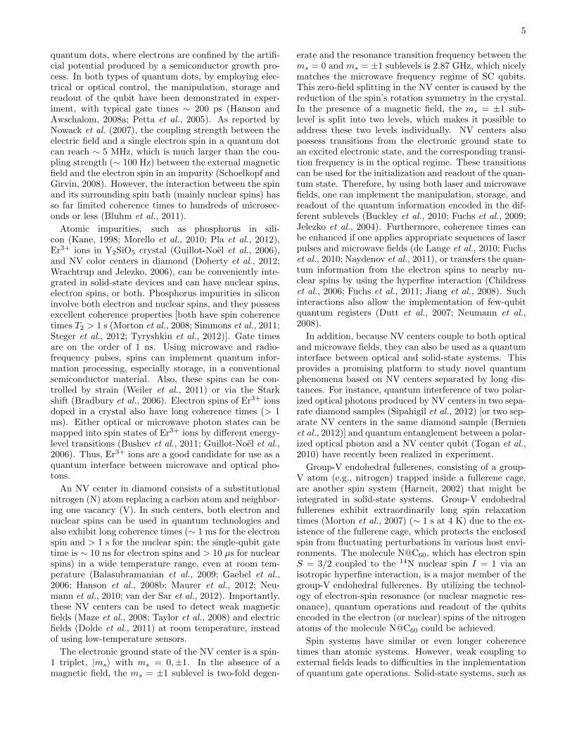
and the electrostatic Coulomb energy EC . Accordingto their topology and physical parameters, SC qubitscan be divided into three kinds: charge qubits (usingCooper-pairs on a small island and EJ/EC < 1), fluxqubits (using the circulating supercurrent states in a loopand EJ/EC > 1), and phase qubits (using the oscilla-tory states of the circuit and EJ/EC > 1), as shown inFig. 2. These solid-state qubits can be controlled by theapplied bias current, gate voltage, and microwave fields.All of these have been demonstrated in various experi-ments (Martinis et al., 2002; Nakamura et al., 1999; vander Wal et al., 2000; Yu et al., 2002). Single-qubit andtwo-qubit gate times are ∼ 1 and ∼ 10–50 ns, respec-tively, while coherence times are currently ∼ 100 µs andare growing steadily. Demonstrating the potential scal-ability of SC qubits, one experiment has integrated 512qubits fabricated on a single chip (Harris, 2012). Thus,SC qubits are promising candidates for future quantumapplications on a chip.
Superconducting qubits are sensitive to environmen-tal noise from extrinsic and intrinsic decohering ele-ments, which leads to short coherence times. Decoher-ence caused by extrinsic elements, such as the local elec-tromagnetic environment, could be reduced using betterdesign of the qubits and the surrounding circuitry, butthe main intrinsic element that limits the coherence re-sults from the hard-to-avoid low-frequency noise. Forcharge qubits, the dominant source of noise is chargefluctuators, such as trapped charges in the substrate andoxide layers of Josephson junctions. For flux and phasequbits, the noise from flux fluctuations dominates the de-coherence. The development of more advanced SC qubitdesigns (Koch et al., 2007; Manucharyan et al., 2009; Youet al., 2007) recently ameliorated this problem.
For example, in three-junction flux qubits (Mooij et al.,1999), the effect of flux noise on the qubit can be reduced
by decreasing EJ , but the charge noise can become in-creasingly important when decreasing EJ . The proposalby You et al. (2006) and You et al. (2007) improved thethree-junction flux-qubit design by reducing the effectiveEJ and adding a large shunt capacitor to the small junc-tion, so as to reduce the effects of both charge and fluxnoise; see Fig. 2. Indeed, a recent experiment (Steffenet al., 2010) demonstrated that this proposal is very ef-fective in ameliorating the effect of low-frequency noise.A complementary proposal for a modified type of chargequbit, named transmon, was put forward by Koch et al.(2007); see Fig. 2. The transmon qubit greatly reducesthe charge dispersion, while the anharmonicity (whichis necessary in order to prevent the qubit from turninginto a harmonic oscillator) decreases by a much smalleramount. Because the qubit becomes less sensitive tocharge variations, the need for electrostatic gates andtuning to a charge sweet spot becomes less necessary.In addition, the qubit in Manucharyan et al. (2009) isanother improved SC qubit which was named fluxonium.In the fluxonium, a small junction is shunted by a seriesarray of large-area tunnel junctions; see Fig. 2. By care-fully choosing the parameters of the tunnel junctions, itis possible to protect the fluxonium from both charge andflux noise.
SC qubits can couple strongly to each other or to cav-ities via electromagnetic fields, which makes fast gateoperations possible with current technology. However,strong coupling also leads to high sensitivity to noiseand therefore short coherence times (several microsec-onds) compared to isolated atoms or spins. Thus, im-proving the coherence properties is a paramount priorityfor SC qubits. Recently, through dynamical decouplingwith a flux qubit (Bylander et al., 2011) or embeddingthe transmon qubit in a 3D circuit QED with a high Qfactor (Paik et al., 2011; Rigetti et al., 2012), coherencetimes of SC qubits have been enhanced to around 10 µs.
D. Cavities and resonators
A cavity is one of the two basic elements of cavityQED (Dutra, 2005; Scully and Zubairy, 1997). The quan-tized electromagnetic field in the cavity can interact withan atom (or spin or SC qubit), and exchange energy withit. Thus, a cavity can serve as a data bus in quantum in-formation processing and transfer quantum data betweendifferent qubits. However, any real cavity system suffersfrom energy losses, which can be described by the qual-ity factor Q. A higher Q factor indicates a lower rate ofenergy loss in the cavity. In general, atoms and spins cou-ple to conventional cavity systems, while SC qubits easilycouple to SC resonators, such as SC coplanar waveguide(CPW) resonators and LC resonators, playing the role ofcavities.

7
Charge qubit
Flux qubit
Phase qubit
Low-
decoherence
qubit
Transmon
Fluxonium
Circuit Properties Dominant
Controlled by .
Behaves like a phase
qubit
Flux fluctuations;
mainly 1/f noise.
Flux fluctuations;
mainly 1/f noise.
V
50Ω
Both charge noise
and flux noise can
be suppressed.
Charge noise can
be suppressed.
Charge noise can
be suppressed with
appropriate
parameters.
noise
Controlled by Vg.
Controlled by
both Vg and .
Controlled by .
Controlled by .
Shunt capacitance .
Shunt capacitance .
Needs an array of
larger-area tunnel
junctions.
EJ
EJ
EJ
EJ
EJ
EJ
αEJ
EJ
EJ
EJ
EJ
EJ
Φe
Φe
Φe
Φe
Controlled byΦe
Φe
Φe
Φe
Ie
Cs
Cs
CinLr
Lr
Cin
CrCs
Cs
Cr LrCJ
EJA
LJA
flux qubit:
phase qubit:
αEJ
Ie
EJ/EC < 1
EJ/EC > 1
0.5 < α < 1α < 0.5
0.5 < α < 1
EJ/EC < 1
EJ/EC > 1
EJ/EC > 1
EJ/EC > 1
EJ/EC > 1
Cg
Cg
Cg
Cg
Vg
Vg
Charge fluctuations;
mainly 1/f noise.
Behaves like a phase
qubit
EJ/EC ≫ 1
FIG. 2 (color online). Different types of superconducting qubits. The basic types are the first three ones from above. Thebottom three can be thought of as improved versions, where additional components have been added.

8
(a) (b)
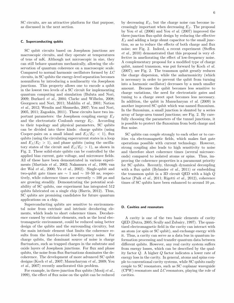
FIG. 3 (color online). Schematic diagram of (a) a cavity and(b) a coplanar waveguide (CPW) resonator.
1. Optical cavities
Many types of cavity systems can be used to couplequbits to electromagnetic fields. The optical cavity con-sisting of two separated parallel mirrors is the most con-ventional cavity system, called the Fabry-Perot cavity,see Fig. 3(a). In such a cavity, a standing-wave electro-magnetic field can exist for a long time and interact withan atom (or spin) trapped in the cavity. With an ap-propriate design, a Fabry-Perot cavity can achieve highquality factors Q ∼ 3 × 10⁸ (Hood et al., 2001), whichprovides a good platform for the realization of cavityQED. In other optical cavity systems, such as the mi-crosphere cavity (dielectric spherically symmetric struc-ture) (Buck and Kimble, 2003; Vernooy et al., 1998),the microtoroidal cavity (dielectric rotationally symmet-ric structure) (Aoki et al., 2006; Armani et al., 2003;
Ozdemir et al., 2011), and the photonic band-gap cav-ity (periodic optical nanostructure that governs the mo-tion of photons) (Greentree et al., 2006; Lev et al., 2004;Song et al., 2005), very high quality factors have also beenachieved. The dynamics of a cavity can be described bythe Hamiltonian:
Hcavity =∑k
h ωk
(a†kak +
1
2
), (1)
where ωk is the frequency of the kth cavity mode, and a†k(ak) is the associated creation (annihilation) operator.
2. Superconducting resonators
Besides the above mentioned cavities, some other res-onators, such as CPW and LC resonators, can also serveas cavities in SC circuits with low losses. These res-onators can be described by the same Hamiltonian asthat given in Eq. (1).
CPW resonators [see Fig. 3(b)] have been realized inseveral experiments (Hofheinz et al., 2009, 2008; Sil-lanpaa et al., 2007; Wallraff et al., 2004). In these SCresonators, two ground planes are placed on the two sidesof a central SC wire; this defines the CPW resonator (ortransmission line resonator). Two gap capacitors play therole of the mirrors in a conventional optical cavity, andthe distance between these capacitors defines the charac-teristic frequencies of the normal modes. Furthermore,
the frequencies of the resonator can be adjusted by in-cluding a superconducting interference device (SQUID)array in the SC wire (Palacios-Laloy et al., 2008). In gen-eral, the entire setup should be on the millimeter scalein order to fit the microwave frequency of the SC qubit,and it can be built by etching techniques. Recent exper-iments showed that gigahertz photons can make up to amillion bounces before being lost in a high quality CPWresonator at low temperatures.
An LC resonator consists of an inductor and a capac-itor with resonance frequency ωr = 1/
√LC. With ap-
propriate design, the LC resonator can be integrated intoa SC circuit and effectively serve as a cavity. Differentfrom a CPW resonator, the LC resonator has only a sin-gle cavity mode.
One recent proposal for creating tunable cavities inSC circuits involves using a one-dimensional array of SCresonators as a medium and two SC qubits as tunablemirrors (Liao et al., 2010; Zhou et al., 2008a,b). The res-onator array supports allowed energy bands for photonpropagation, just as in a photonic crystal. When the fre-quency of a qubit that is coupled to one of the resonatorsis tuned to match the photon frequency, it can act likea perfectly reflecting mirror. Thus, by appropriately bi-asing two qubits coupled to two resonators in the array,one obtains an analog of a Fabry-Perot cavity.
3. Nanomechanical resonators
NAMRs have recently attracted considerable attentionfor their possible applications in future quantum tech-nologies. With current experimental techniques, NAMRscan be built with quality factors Q in the range of 103
to 105, and fundamental vibrational mode frequencies inthe range from 10 MHz to 1 GHz, at low temperaturesT (Cleland and Roukes, 1996; Gaidarzhy et al., 2005;Knobel and Cleland, 2003; LaHaye et al., 2004). If thevibrational energy of the NAMR becomes larger than thethermal energy kBT , then the mechanical oscillation canbehave quantum mechanically. However, the observa-tion of quantum behavior is challenging since it requirescooling the mechanical motion to extremely low tempera-tures and the ability to generate nonclassical states. Cur-rently, many groups are devoting tremendous efforts todevising hybrid systems to create a coherent interfacebetween NAMRs and other well-controlled quantum sys-tems. Some focus on optomechanical systems involvingan oscillating cantilever or an oscillating micromirror as aharmonic oscillator (Marquardt and Girvin, 2009). Oth-ers focus on how to integrate NAMRs into SC circuits andcouple them to each other (Armour et al., 2002; Buks andBlencowe, 2006; Cleland and Geller, 2004; Etaki et al.,2008; LaHaye et al., 2009; Liu et al., 2010; O’Connellet al., 2010; Pugnetti et al., 2009; Shevchenko et al., 2012;Sun et al., 2006; Teufel et al., 2011; Wang et al., 2008; Weiet al., 2006; Xia and Evers, 2009; Xue et al., 2007a,b,c;Zhang et al., 2009b, 2005).
9
III. CAVITY QUANTUM ELECTRODYNAMICS
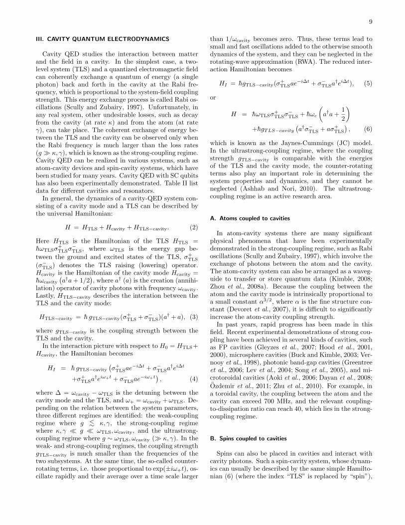
Cavity QED studies the interaction between matterand the field in a cavity. In the simplest case, a two-level system (TLS) and a quantized electromagnetic fieldcan coherently exchange a quantum of energy (a singlephoton) back and forth in the cavity at the Rabi fre-quency, which is proportional to the system-field couplingstrength. This energy exchange process is called Rabi os-cillations (Scully and Zubairy, 1997). Unfortunately, inany real system, other undesirable losses, such as decayfrom the cavity (at rate κ) and from the atom (at rateγ), can take place. The coherent exchange of energy be-tween the TLS and the cavity can be observed only whenthe Rabi frequency is much larger than the loss rates(g κ, γ), which is known as the strong-coupling regime.Cavity QED can be realized in various systems, such asatom-cavity devices and spin-cavity systems, which havebeen studied for many years. Cavity QED with SC qubitshas also been experimentally demonstrated. Table II listdata for different cavities and resonators.
In general, the dynamics of a cavity-QED system con-sisting of a cavity mode and a TLS can be described bythe universal Hamiltonian:
H = HTLS +Hcavity +HTLS−cavity. (2)
Here HTLS is the Hamiltonian of the TLS HTLS =hωTLSσ
+TLSσ
−TLS, where ωTLS is the energy gap be-
tween the ground and excited states of the TLS, σ+TLS
(σ−TLS) denotes the TLS raising (lowering) operator.Hcavity is the Hamiltonian of the cavity mode Hcavity =hωcavity
(a†a+ 1/2
), where a† (a) is the creation (annihi-
lation) operator of cavity photons with frequency ωcavity.Lastly, HTLS−cavity describes the interation between theTLS and the cavity mode:
HTLS−cavity = h gTLS−cavity(σ+TLS + σ−TLS)(a† + a), (3)
where gTLS−cavity is the coupling strength between theTLS and the cavity.
In the interaction picture with respect to H0 = HTLS+Hcavity, the Hamiltonian becomes
HI = h gTLS−cavity
(σ+
TLSae−i∆t + σ−TLSa
†ei∆t
+σ+TLSa
†eiω+t + σ−TLSae−iω+t
), (4)
where ∆ = ωcavity − ωTLS is the detuning between thecavity mode and the TLS, and ω+ = ωcavity +ωTLS. De-pending on the relation between the system parameters,three different regimes are identified: the weak-couplingregime where g <∼ κ, γ, the strong-coupling regimewhere κ, γ g ωTLS, ωcavity, and the ultrastrong-coupling regime where g ∼ ωTLS, ωcavity ( κ, γ). In theweak- and strong-coupling regimes, the coupling strengthgTLS−cavity is much smaller than the frequencies of thetwo subsystems. At the same time, the so-called counter-rotating terms, i.e. those proportional to exp(±iω+t), os-cillate rapidly and their average over a time scale larger
than 1/ωcavity becomes zero. Thus, these terms lead tosmall and fast oscillations added to the otherwise smoothdynamics of the system, and they can be neglected in therotating-wave approximation (RWA). The reduced inter-action Hamiltonian becomes
HI = hgTLS−cavity(σ+TLSae
−i∆t + σ−TLSa†ei∆t), (5)
or
H = hωTLSσ+TLSσ
−TLS + hωc
(a†a+
1
2
)+hgTLS−cavity
(a†σ−TLS + aσ+
TLS
), (6)
which is known as the Jaynes-Cummings (JC) model.In the ultrastrong-coupling regime, where the couplingstrength gTLS−cavity is comparable with the energiesof the TLS and the cavity mode, the counter-rotatingterms also play an important role in determining thesystem properties and dynamics, and they cannot beneglected (Ashhab and Nori, 2010). The ultrastrong-coupling regime is an active research area.
A. Atoms coupled to cavities
In atom-cavity systems there are many significantphysical phenomena that have been experimentallydemonstrated in the strong-coupling regime, such as Rabioscillations (Scully and Zubairy, 1997), which involve theexchange of photons between the atom and the cavity.The atom-cavity system can also be arranged as a waveg-uide to transfer or store quantum data (Kimble, 2008;Zhou et al., 2008a). Because the coupling between theatom and the cavity mode is intrinsically proportional toa small constant α3/2, where α is the fine structure con-stant (Devoret et al., 2007), it is difficult to significantlyincrease the atom-cavity coupling strength.
In past years, rapid progress has been made in thisfield. Recent experimental demonstrations of strong cou-pling have been achieved in several kinds of cavities, suchas FP cavities (Gleyzes et al., 2007; Hood et al., 2001,2000), microsphere cavities (Buck and Kimble, 2003; Ver-nooy et al., 1998), photonic band-gap cavities (Greentreeet al., 2006; Lev et al., 2004; Song et al., 2005), and mi-crotoroidal cavities (Aoki et al., 2006; Dayan et al., 2008;
Ozdemir et al., 2011; Zhu et al., 2010). For example, ina toroidal cavity, the coupling between the atom and thecavity can exceed 700 MHz, and the relevant coupling-to-dissipation ratio can reach 40, which lies in the strong-coupling regime.
B. Spins coupled to cavities
Spins can also be placed in cavities and interact withcavity photons. Such a spin-cavity system, whose dynam-ics can usually be described by the same simple Hamilto-nian (6) (where the index “TLS” is replaced by “spin”),

10
TABLE II. Relevant parameters for different types of cavities in recent experiments.
TypeFrequency
(Hz)
Temperature
(K)
Coupling
strength
g/(2π) (MHz)
Coupling to
decay ratio
g/max(κ, γ)
Cooperativity
g2/κγ
Quality factor
Q
Fabry-Perot cavity
(Hood et al., 2000)1.9× 10¹⁴ 3× 10² 110 7.7 ∼ 30 > 106
Microsphere cavity
(Vernooy et al., 1998)3.5× 10¹⁴ ∼ 10 20 2.9 22 1.5× 10⁶
Microtoroidal cavity
(Aoki et al., 2006)
(Dayan et al., 2008)
1.9× 10¹⁴ 10−5 70 3.9 ∼ 11 ∼ 108
Photonic band-gap
cavity
(Lev et al., 2004)
3.5× 10¹⁴ 3× 10² 1.7× 10⁴ 3.9 2.5× 10⁴ 4× 10⁴
Coplanar waveguide
resonator
(Niemczyk et al., 2010)
5.4× 10⁹ 10−5 > 3× 10² > 102 > 104 > 108
LC resonator
(Forn-Dıaz et al., 2010)8.1× 10⁹ 10−5 820 > 10 4× 10⁴ ∼ 103
can therefore be employed to realize cavity QED. Fur-thermore, most spin systems, such as electron spins inquantum dots that are embedded in a solid-state chipand controlled by voltages, exhibit good scalability andtunability, which are vital elements for experimentallyobserving cavity-QED phenomena and designing quan-tum devices.
In the past few years, spin-cavity systems have beentheoretically analyzed and experimentally demonstrated.Quantum dots can be integrated into micropillar cav-ities (Press et al., 2007; Reithmaier et al., 2004), mi-crodisk cavities (Imamoglu et al., 1999; Peter et al., 2005;Witzany et al., 2011), or photonic crystal cavities (Carteret al., 2012; Faraon et al., 2008; Hennessy et al., 2007;Nomura et al., 2010; Yoshie et al., 2004), and strong cou-pling with the photon field in the cavity can be achieved.Atomic impurity spins, especially NV centers, can alsocouple to microsphere cavities (Park et al., 2006), micro-toroidal cavities (Chen et al., 2011), or photonic crystalcavities (Su et al., 2009; Tomljenovic-Hanic et al., 2006;Zagoskin et al., 2007).
C. Superconducting qubits coupled to resonators
Recently, a growing new subfield in SC qubit researchis finding physical phenomena in SC circuits analogousto the ones in atomic physics and quantum optics. A
high quality microwave resonator can be coupled to SCqubits, which can be used to realize cavity-QED wherethe SC qubit is regarded as an artificial atom (Bulutaet al., 2011; You and Nori, 2005, 2011). The resonatorcan be either a CPW resonator or an LC resonator. Thedynamics of such SC circuits can be described by theHamiltonian in Eq. (4), where the index TLS is replacedby SC denoting the SC qubit. In this Hamiltonian, thedecay from the resonator and spontaneous emission areneglected.
The coupling strength between matter and the cav-ity mode is determined by both the transition dipolemoment and the vacuum field strength. A SC qubitcan have a large effective transition dipole moment, e.g.,the effective electric dipole moment of a charge qubit is∼ 104 times larger than that of an alkali atom (Blaiset al., 2004). Moreover, in a quasi-1D cavity, such asa CPW resonator, the microwave field is confined to amuch smaller volume than in a conventional 3D opticalor microwave cavity. This can make the field strengthin the quasi-1D cavity much larger (about 100 times ormore) than in a 3D cavity. Owing to the large dipolemoment of a SC qubit and the strong electromagneticfield in a quasi-1D cavity, the SC qubit can couple to thequasi-1D cavity mode much more strongly than an atomor a spin couples to a 3D cavity. Therefore, it becomeseasier to reach the strong, or even ultrastrong, couplingregime using a SC circuit consisting of a SC qubit and a

11
Charge
qubit
Flux
qubit
Phase
qubit
LC oscillator Coplanar waveguide resonator
(a)
(b)
(c)
Electric field
Magnetic field
FIG. 4 (color online). Schematic diagrams of LC resonators (second column) and coplanar waveguide resonators (third column)coupled to three types of superconducting qubits.
quasi-1D cavity. Indeed, the strong (Wallraff et al., 2004)and ultrastrong (Niemczyk et al., 2010) coupling regimeshave been experimentally realized in this SC-cavity sys-tem. In the usual strong-coupling regime, the counter-rotating terms (i.e., σ+
SCa† and σ−SCa) can be neglected
and the RWA is valid. However, in the ultrastrong-coupling regime (Ashhab and Nori, 2010), the counter-rotating terms also play an important role and cannot beneglected. Note that either an atom or a spin can also beplaced in a quasi-1D cavity (see Sec. IV.A), but its cou-pling to the quasi-1D cavity mode is still much smallerthan that of a SC qubit because the SC qubit has a much
larger transition dipole moment.
For charge qubits, electric fields are well suited for cou-pling to the qubits (You et al., 2003). Note that chargequbits can also be designed with a loop, such that theycan also interact with magnetic fields (You and Nori,2003). A SC circuit involving a CPW resonator and acharge qubit was theoretically proposed by Blais et al.(2004, 2007) and experimentally demonstrated by Wall-raff et al. (2004), where a strong electric coupling betweena single photon and a charge qubit was achieved. In thissetup, a charge qubit with two identical Josephson junc-tions is integrated into the ground planes of the trans-

12
mission line at or near the antinode of the standing waveof the voltage on the SC wire for maximum coupling, asshown in Fig. 4. The dynamics of this system can be de-scribed by the Hamiltonian in Eq. (4), and the strengthof the coupling between the charge qubit and the SCresonator can in principle reach the ultrastrong-couplingregime (Devoret et al., 2007). A similar structure (Fig. 4)and mechanism are also used for the electric coupling ofphase qubits with SC resonators (Hofheinz et al., 2009,2008; Sillanpaa et al., 2007), where the phase qubits areplaced on the two sides of the transmission line and cou-pled to it via capacitors, sitting on two antinodes of theelectric field. The photon in the CPW resonator acts as aquantum bus that transfers quantum states between thetwo phase qubits.
Flux qubits can also couple to CPW resonators viathe induced magnetic field (Niemczyk et al., 2010; Per-opadre et al., 2010; Yang et al., 2003, 2004), as shownin Fig. 4. A flux qubit placed at or near an antinodeof the standing wave of the current on the SC wire, canstrongly couple to the SC resonator via the mutual in-ductance. In such a SC circuit, the vacuum Rabi split-ting in the transmission spectrum was observed, whichmeans that strong coupling was achieved. Furthermore,by placing an additional Josephson junction at the cen-tral SC wire, where the flux qubit is fabricated, the in-ductive coupling between the qubit and the resonator canbe enhanced and can bring the system to the ultrastrong-coupling regime (Niemczyk et al., 2010).
The other type of resonators, LC resonators, can alsobe integrated into SC circuits and can couple to chargeand phase qubits via capacitors (electric field) or fluxqubits via the mutual inductance (magnetic field), seeFig. 4. For example, in flux qubits, the lowest two quan-tum states, which have clockwise and anticlockwise su-percurrents in the qubit loop, are used to denote the twobasis states of the qubit. By employing the magnetic fieldproduced by the current, the flux qubit can strongly cou-ple to the LC circuit via a large mutual inductance be-tween them. Such flux qubit-resonator systems have beenexperimentally demonstrated and vacuum Rabi oscilla-tions have also been observed in experiment (Chiorescuet al., 2004; Johansson et al., 2006), where a three-junction flux qubit is enclosed by a SQUID that is in-ductively coupled to the qubit. Recently, Forn-Dıaz et al.(2010) observed the Bloch-Siegert shift in this flux qubit-resonator system and demonstrated that the couplingstrength between them can lie in the ultrastrong-couplingregime.
(b)
(a)(a)
(b)
Trapped atoms
Impurity spins
FIG. 5 (color online). Schematic diagrams of coplanar waveg-uide resonators with (a) atoms or (b) spins. The sinusoidalcurves describe the electric field in the coplanar waveguideresonator and the yellow concentric circles in (b) denote themagnetic field.
IV. THEORETICAL PRINCIPLES AND PROPOSALSFOR HYBRID SYSTEMS INTEGRATING ATOMS ORSPINS IN SUPERCONDUCTING CIRCUITS
A. Atoms or spins coupled to superconducting resonators(without superconducting qubits)
Besides SC qubits, atoms and spins can also coupleto CPW resonators, producing a hybrid cavity-QED sys-tem. Atoms can be trapped either by electrostatic ormagnetic fields generated by the chip or by trapping po-tentials from externally applied laser beams (Andre et al.,2006; Rabl and Zoller, 2007), and couple to a CPW res-onator on the chip (Andre et al., 2006; Deng et al., 2010;Petrosyan et al., 2009; Rabl et al., 2006; Rabl and Zoller,2007; Tordrup and Mølmer, 2008; Tordrup et al., 2008;Verdu et al., 2009; Zhang et al., 2009a), see Fig. 5(a).
Without extra trapping techniques, impurity spins,such as NV centers in diamond, can couple to a CPWresonator by placing the diamond sample on the res-onator, or impurities can be directly created in the Sisubstrate (Amsuss et al., 2011; Bushev et al., 2011;Imamoglu, 2009; Kubo et al., 2012, 2010; Ping et al.,2012; Ranjan et al., 2013; Sandner et al., 2012; Schuster

13
(a)(a)
Quantum dot
in a nanowire
Electrostatically-
defined quantum dot
(b)
FIG. 6 (color online). Schematic diagram of coplanar waveg-uide resonators with spins in quantum dots. The sinusoidalcurves describe the electric field in the coplanar waveguideresonator. (a) A nanowire quantum dot, and (b) an electro-statically defined quantum dot.
et al., 2010; Wesenberg et al., 2009; Yang et al., 2011a,b),as shown in Fig. 5(b).
In addition, quantum dots can also be integrated intoa CPW resonator and coupled to the electromagneticfield in the resonator (Childress et al., 2004), as shownin Fig. 6. There have been a few recent proposals forcoupling the spin state of the quantum dot to the elec-tric field in the CPW resonator, generally mediated bythe orbital state. In all of these proposals, the cou-pling between the field of the resonator and the or-bital state is the electric-dipole coupling. The couplingbetween the spin state and the orbital state could beachieved via the application of an inhomogeneous mag-netic field (Burkard and Imamoglu, 2006; Cottet andKontos, 2010; Hu et al., 2012), spin-orbit coupling (Huet al., 2012; Trif et al., 2008) or the exchange interac-tion (Jin et al., 2012). A number of recent experimentshave demonstrated the coupling between quantum dotsand CPW resonators.Delbecq et al. (2011) and Frey et al.(2012) demonstrated the coupling by using the dispersivefrequency shift of the resonator as a probe for the chargestate of the quantum dots. The results obtained using theresonator agreed with those obtained through transportmeasurements. In another experiment (Petersson et al.,
2012), a spin qubit in a double quantum dot was manipu-lated via a classical microwave signal applied through theCPW resonator, with the spin-charge interface providedby the spin-orbit interaction. More recently, strong cou-pling between a CPW resonator and the charge degreeof freedom of a double quantum dot was demonstratedthrough the observation of the vacuum Rabi splittingin spectroscopic measurements of the resonator (Toidaet al., 2013). All of these experiments can be seen asfirst steps towards the coherent coupling between thespin state of quantum dots and a SC resonator in thefew-photon regime.
B. Atoms or spins coupled to superconducting resonatorsand qubits
In an ideal HQC, the SC circuit provides the advantageof scalability on a small chip owing to the rapid progresson micro-lithography and micro-etching techniques, aswell as ease of control due to the strong coupling of SCqubits with external fields. At the same time, atoms andspins can be integrated into the circuit by using trappingor doping techniques. Such a HQC involving SC qubitsand atoms (or spins) thereby combines “the best of twoworlds”: the rapid operations of the SC circuits and thelong coherence times of the atoms (or spins), as well asscalability, see Fig. 7.
However, effectively integrating such systems and con-trolling the resultant hybrid circuits are still a challenge.In the remainder of this section, we first introduce thebasic mechanisms of HQCs, and then highlight recenttheoretical proposals and experimental demonstrationsfor implementing various types of HQCs.
Atoms and spins can be initialized, manipulated andmeasured through their interaction with electromagneticfields. SC qubits also interact with electromagnetic fields,which are used to initialize, manipulate and measurethem. Therefore, electromagnetic fields can be utilizedto couple atomic (or spin) systems to SC qubits in orderto facilitate the transfer of information between the twosystems.
There are two different types of coupling to electro-magnetic fields: electric coupling and magnetic cou-pling. Generally, most atomic systems (including ionsand molecules) couple to photons via the electric field,while spins involve magnetic coupling. Moreover, elec-tric fields are well suited for coupling to SC charge andphase qubits, while flux qubits couple more easily to mag-netic fields threading the qubit loop. Note that chargequbits can also be designed with a loop, such that theyalso interact with magnetic fields.
Atoms (or spins) and SC qubits can interact with eachother directly through electric or magnetic fields. Al-ternatively, they can be linked indirectly via a quantum“bridge” or data bus, which mediates the exchange ofquantum information between the atomic (or spin) mem-ory and the SC processor.
14
Processor
Atoms or spins
Memory
Direct coupling
N
Data bus
Coplanar
waveguide resonator
Indirect coupling
V
Superconducting circuit
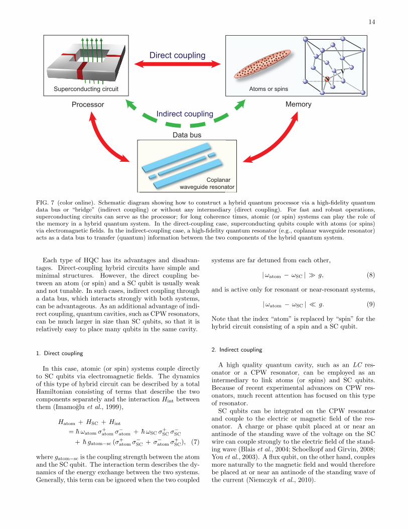
FIG. 7 (color online). Schematic diagram showing how to construct a hybrid quantum processor via a high-fidelity quantumdata bus or “bridge” (indirect coupling) or without any intermediary (direct coupling). For fast and robust operations,superconducting circuits can serve as the processor; for long coherence times, atomic (or spin) systems can play the role ofthe memory in a hybrid quantum system. In the direct-coupling case, superconducting qubits couple with atoms (or spins)via electromagnetic fields. In the indirect-coupling case, a high-fidelity quantum resonator (e.g., coplanar waveguide resonator)acts as a data bus to transfer (quantum) information between the two components of the hybrid quantum system.
Each type of HQC has its advantages and disadvan-tages. Direct-coupling hybrid circuits have simple andminimal structures. However, the direct coupling be-tween an atom (or spin) and a SC qubit is usually weakand not tunable. In such cases, indirect coupling througha data bus, which interacts strongly with both systems,can be advantageous. As an additional advantage of indi-rect coupling, quantum cavities, such as CPW resonators,can be much larger in size than SC qubits, so that it isrelatively easy to place many qubits in the same cavity.
1. Direct coupling
In this case, atomic (or spin) systems couple directlyto SC qubits via electromagnetic fields. The dynamicsof this type of hybrid circuit can be described by a totalHamiltonian consisting of terms that describe the twocomponents separately and the interaction Hint betweenthem (Imamoglu et al., 1999),
Hatom + HSC + Hint
= h ωatom σ+atom σ−atom + h ωSC σ
+SC σ
−SC
+ h gatom−sc (σ+atom σ−SC + σ−atom σ+
SC), (7)
where gatom−sc is the coupling strength between the atomand the SC qubit. The interaction term describes the dy-namics of the energy exchange between the two systems.Generally, this term can be ignored when the two coupled
systems are far detuned from each other,
|ωatom − ωSC | g, (8)
and is active only for resonant or near-resonant systems,
|ωatom − ωSC | g. (9)
Note that the index “atom” is replaced by “spin” for thehybrid circuit consisting of a spin and a SC qubit.
2. Indirect coupling
A high quality quantum cavity, such as an LC res-onator or a CPW resonator, can be employed as anintermediary to link atoms (or spins) and SC qubits.Because of recent experimental advances on CPW res-onators, much recent attention has focused on this typeof resonator.
SC qubits can be integrated on the CPW resonatorand couple to the electric or magnetic field of the res-onator. A charge or phase qubit placed at or near anantinode of the standing wave of the voltage on the SCwire can couple strongly to the electric field of the stand-ing wave (Blais et al., 2004; Schoelkopf and Girvin, 2008;You et al., 2003). A flux qubit, on the other hand, couplesmore naturally to the magnetic field and would thereforebe placed at or near an antinode of the standing wave ofthe current (Niemczyk et al., 2010).

15
In a frame rotating at the cavity frequency, the dynam-ics of this system can be described by the Hamiltonian:
HSC + Hsc−cavity
=h δSC
2σz
SC + h gsc−cavity(σ+SC a + σ−SC a
†),(10)
where δSC is the detuning of the SC qubit from the reso-nance frequency of the cavity, and gsc−cavity denotes thecoupling strength between the SC qubit and the cavityfield.
Atoms (or spins) can also be integrated on the CPWresonator and couple to the electromagnetic field (Andreet al., 2006; Petrosyan et al., 2009; Rabl et al., 2006;Rabl and Zoller, 2007; Tordrup and Mølmer, 2008; Tor-drup et al., 2008; Verdu et al., 2009), as described inSec. IV.A. The dynamics of this system, consisting of asingle atom (or spin) and a cavity, can be described bythe Hamiltonian:
Hatom + Hatom−cavity
= h δatom σ+atom σ−atom
+ h gatom−cavity
(σ+
atom a + σ−atom a†), (11)
where δatom denotes the atom-cavity detuning, andgatom−cavity is the coupling strength between the singleatom and the field. For a spin-cavity system, the index“atom” in Eq. (11) is replaced by “spin”. If an ensem-ble with N atoms (or spins) is utilized, the Hamiltoniantakes the Tavis-Cummings form,
Hatom + Hatom−cavity
= h δatom π†atom πatom
+ h g′atom−cavity
(π†atom a + πatom a†
), (12)
where πatom = (1/√N)∑
i σ−atom,i [π†atom =
(1/√N)∑
i σ+atom,i] is the collective atomic an-
nihilation (excitation) operator, and the index idenotes the different atoms (or spins) in the ensem-ble. Here the effective coupling strength becomesg′atom(spin)−cavity =
√Ngatom(spin)−cavity (Dicke, 1954),
which helps achieve strong coupling between the atoms(or spins) and the cavity. It should be noted, however,that the effective coupling strength cannot be increasedindefinitely by increasing the size of the cavity and alongwith it the number of atoms (or spins) that can fit insidethe cavity. If the size of the cavity is increased, thecoupling strength per atom (or spin) decreases as theinverse of the square-root of the mode volume, such thatthe gain in increasing number is counterbalanced by thereduction in coupling strength per atom (or spin).
There are two main protocols for transferring quantuminformation through the intermediary bridge: via the ex-change of either real or virtual photons. In the case ofreal-photon-based protocols, when two subsystems arecoupled to a fixed cavity, one subsystem can be tunedinto resonance with the cavity for a period of time to
transfer the quantum information from the subsystem tothe cavity and then the other subsystem is tuned intoresonance with the cavity for a period of time, so as tofinally transfer the quantum information into this lattersubsystem. Alternatively, if the cavity is tunable, it canbe tuned into resonance with one of the two subsystemsfor a period of time such that quantum information istransferred from the subsystem to the cavity, and thenthe cavity is tuned into resonance with the other sub-system for another period of time to complete the infor-mation transfer. In the case of virtual-photon-mediatedinteractions, the atoms (or spins) and the SC qubit aretuned into resonance with each other, while the cavity isoff-resonance with them and typically has a higher fre-quency. The cavity can then be adiabatically eliminatedfrom the physical picture, leading to the effective interac-tion Hamiltonian (Frohlich, 1950; Imamoglu et al., 1999;Nakajima, 1955)
Heff = h geff (σ+atom σ−SC + σ−atom σ+
SC). (13)
The effective coupling strength is
geff =gatom−cavity gsc−cavity
∆, (14)
where ∆ is the detuning of the two systems from thecavity frequency.
In order to achieve much longer coherence times in spinensembles, the information could further be transferredfrom electron spins to nuclear spins by using hyperfineinteractions between them (Amsuss et al., 2011; Childresset al., 2006; Dutt et al., 2007; Jiang et al., 2008; van derSar et al., 2012; Wu et al., 2010). This would improve thecoherence times from several hundred microseconds inthe electron spins to seconds in the nuclear spins, whichwould be a great improvement.
C. Direct-coupling hybrid circuits
Recently, Marcos et al. (2010) proposed a hybrid SCcircuit with a three-junction flux qubit magnetically cou-pled to a single NV center or an ensemble of NV cen-ters in diamond located at the center of the SC loop,as shown in Fig. 8(a). These two systems have similarenergy splittings: the energy gap between the two eigen-states of the flux qubit is typically a few GHz, whilethe NV centers’ electronic ground state has a zero-fieldsplitting ∆ ∼ 2π × 2.87 GHz between the ms = 0 andms = ±1 sublevels. By introducing an external mag-netic field W ext, the NV center can be tuned into res-onance with the flux qubit, and the flux qubit can bebrought near the degeneracy point of the clockwise andanticlockwise supercurrent states, which produce an ad-ditional magnetic field WFQ. The interaction betweenthe NV centers and the magnetic field produced by theflux qubit leads to a coupling between the two systems.
The details can be described as follows. The axis of theNV centers is defined as the z-axis and it can be taken

16
(a)
(b)(b)
Flux qubit
NV centers
FIG. 8 (color online). (a) Schematic diagram of a hybrid sys-tem consisting of a spin ensemble and a superconducting fluxqubit. (b) Schematic diagram of a hybrid system integratingthe unit in (a) with a superconducting resonator.
to lie in the plane of the flux qubit. The component ofthe external field that is parallel to the z-axis isolates theNV center as a two-level subsystem involving the statesms = 0 and ms = +1, while the component of the fieldthat is perpendicular to the qubit loop is set to half a fluxquantum and brings the flux qubit near the degeneracypoint. The dynamics of this process can be described bythe Hamiltonian:
H =ε
2σz + λσx +DS2
z +W extz Sz + σz ~W
FQ · ~S, (15)
where ~σ denotes the Pauli operators of the flux qubit, ~Sdescribes the spin of the NV center, λ is the tunnelingstrength between the two supercurrents states, and ε isthe bias in the two-well limit of the flux qubit, whichis controlled by the external field perpendicular to thequbit loop. D = 2.87 GHz is the zero-field splitting ofthe NV center. W ext
z = geµBBz is the parallel componentof the external magnetic field, which adjusts the energy
splitting of the NV center and ~WFQ corresponds to theinduced magnetic field of the two currents of the fluxqubit.
By rotating the flux-qubit terms by an angle cos θ ≡ε/2ω (where ω ≡
√ε2/4 + λ2) via a unitary transforma-
tion and making the RWA, the effective Hamiltonian (ina frame rotating with frequency ω) of near-resonance in-
teraction between the NV center and the flux qubit canbe obtained from Eq. (15):
Heff =δ
2σsz+
cos θ
2WFQ
z σzσsz+
(sin θ√
2WFQ⊥ σ−σ
s+ +H.c.
),
(16)where ~σs denotes the Pauli operators of the electron-spinstates of the NV center, ~σ refers to the Pauli operatorsof the the flux qubit in the rotated basis describing thetwo eigenstates of the flux qubit, and δ = D +W ext
z − ωis the detuning of the NV center from the eigenenergyof the flux qubit. The last two terms of this effectiveHamiltonian describe the exchange of energy between theNV center and the flux qubit.
In order to obtain the maximum gmax (= WFQ⊥ /√
2)
of the coupling strength g = sin θWFQ⊥ /√
2, one can biasthe flux qubit at the degeneracy point ε = 0, where θ =π/2. Simultaneously, at this point the energy levels anddynamics are insensitive to small fluctuations of ε.
With a flux qubit of size L ∼ 1 µm and critical cur-rent IC ∼ 0.5 µA, the coupling strength between theNV center and the flux qubit is g/2π ∼ 10 kHz (Marcoset al., 2010). However, the effective coupling betweenthe flux qubit and a single NV center is too weak for anyrealistic demonstration, using current technology. Thiscoupling strength can be enhanced by reducing the sizeof the flux qubit or replacing the single NV center withan ensemble (Marcos et al., 2010). Recently, this pro-posal was demonstrated in experiment (Zhu et al., 2011)[introduced in Sec. V.A]. However, because the size ofthe flux qubit limits the number of NV centers in theensemble, the coupling strength cannot be substantiallyenhanced in this way.
This circuit can also achieve the coherent coupling oftwo or more NV centers by employing the flux qubit asa virtual intermediary, which is a possible protocol toeventually implement many-qubit quantum gate opera-tions for spins. In addition, if one could integrate thiscircuit encompassing a single NV center in a CPW res-onator, as shown in Fig. 8(b), the single NV center couldbe effectively coupled to the photon via the magnetic fieldin the resonator (Twamley and Barrett, 2010). Further-more, this proposal can also be used to couple an atomensemble and a flux qubit. For example, Hoffman et al.(2011) has discussed a scheme to couple trapped 87Rbatoms to a flux qubit via magnetic-dipole coupling, wherethe atoms are trapped by an ultrathin fiber to less than10 µm above the surface of the flux qubit. Also, basedon the strong coupling between the spin ensemble andthe flux qubit and the tunable coupling between nearest-neighbor flux qubits, one can construct a hybrid arraywith flux qubits and NV centers to simulate a Jaynes-Cummings lattice (Hummer et al., 2011), which can beused to demonstrate the transition between localized anddelocalized phases.
17
R
h
Atom or solid-state qubit
L
Atom(a)
Ion
trap
Coaxial
cavity
Charge
qubit
(b)
Rr Lr Cm
EJ
Vtrap
Rb
Rb
Cib
Cib
Cr
2
Cr
2
Vb2
Vb1
Vg
Cg
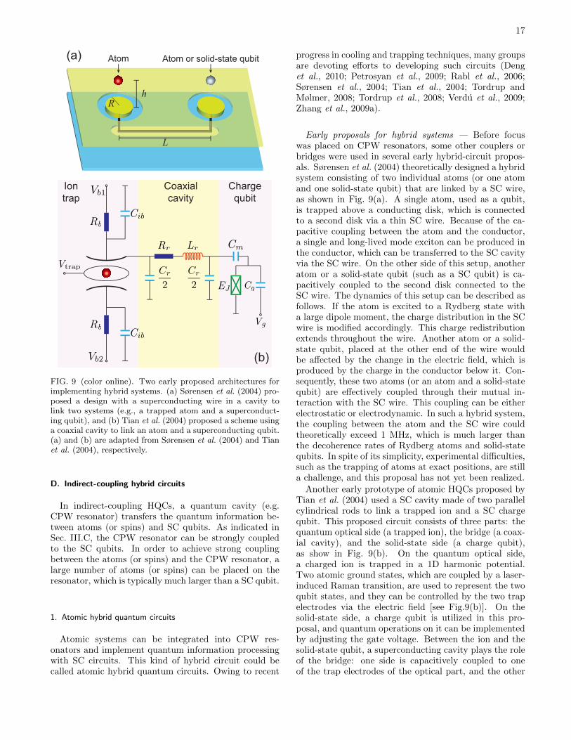
FIG. 9 (color online). Two early proposed architectures forimplementing hybrid systems. (a) Sørensen et al. (2004) pro-posed a design with a superconducting wire in a cavity tolink two systems (e.g., a trapped atom and a superconduct-ing qubit), and (b) Tian et al. (2004) proposed a scheme usinga coaxial cavity to link an atom and a superconducting qubit.(a) and (b) are adapted from Sørensen et al. (2004) and Tianet al. (2004), respectively.
D. Indirect-coupling hybrid circuits
In indirect-coupling HQCs, a quantum cavity (e.g.CPW resonator) transfers the quantum information be-tween atoms (or spins) and SC qubits. As indicated inSec. III.C, the CPW resonator can be strongly coupledto the SC qubits. In order to achieve strong couplingbetween the atoms (or spins) and the CPW resonator, alarge number of atoms (or spins) can be placed on theresonator, which is typically much larger than a SC qubit.
1. Atomic hybrid quantum circuits
Atomic systems can be integrated into CPW res-onators and implement quantum information processingwith SC circuits. This kind of hybrid circuit could becalled atomic hybrid quantum circuits. Owing to recent
progress in cooling and trapping techniques, many groupsare devoting efforts to developing such circuits (Denget al., 2010; Petrosyan et al., 2009; Rabl et al., 2006;Sørensen et al., 2004; Tian et al., 2004; Tordrup andMølmer, 2008; Tordrup et al., 2008; Verdu et al., 2009;Zhang et al., 2009a).
Early proposals for hybrid systems — Before focuswas placed on CPW resonators, some other couplers orbridges were used in several early hybrid-circuit propos-als. Sørensen et al. (2004) theoretically designed a hybridsystem consisting of two individual atoms (or one atomand one solid-state qubit) that are linked by a SC wire,as shown in Fig. 9(a). A single atom, used as a qubit,is trapped above a conducting disk, which is connectedto a second disk via a thin SC wire. Because of the ca-pacitive coupling between the atom and the conductor,a single and long-lived mode exciton can be produced inthe conductor, which can be transferred to the SC cavityvia the SC wire. On the other side of this setup, anotheratom or a solid-state qubit (such as a SC qubit) is ca-pacitively coupled to the second disk connected to theSC wire. The dynamics of this setup can be described asfollows. If the atom is excited to a Rydberg state witha large dipole moment, the charge distribution in the SCwire is modified accordingly. This charge redistributionextends throughout the wire. Another atom or a solid-state qubit, placed at the other end of the wire wouldbe affected by the change in the electric field, which isproduced by the charge in the conductor below it. Con-sequently, these two atoms (or an atom and a solid-statequbit) are effectively coupled through their mutual in-teraction with the SC wire. This coupling can be eitherelectrostatic or electrodynamic. In such a hybrid system,the coupling between the atom and the SC wire couldtheoretically exceed 1 MHz, which is much larger thanthe decoherence rates of Rydberg atoms and solid-statequbits. In spite of its simplicity, experimental difficulties,such as the trapping of atoms at exact positions, are stilla challenge, and this proposal has not yet been realized.
Another early prototype of atomic HQCs proposed byTian et al. (2004) used a SC cavity made of two parallelcylindrical rods to link a trapped ion and a SC chargequbit. This proposed circuit consists of three parts: thequantum optical side (a trapped ion), the bridge (a coax-ial cavity), and the solid-state side (a charge qubit),as show in Fig. 9(b). On the quantum optical side,a charged ion is trapped in a 1D harmonic potential.Two atomic ground states, which are coupled by a laser-induced Raman transition, are used to represent the twoqubit states, and they can be controlled by the two trapelectrodes via the electric field [see Fig.9(b)]. On thesolid-state side, a charge qubit is utilized in this pro-posal, and quantum operations on it can be implementedby adjusting the gate voltage. Between the ion and thesolid-state qubit, a superconducting cavity plays the roleof the bridge: one side is capacitively coupled to oneof the trap electrodes of the optical part, and the other
18
(a)
(b)
(a)
(b)
Trapped atoms
Trapped atoms
Charge qubits
Charge qubits
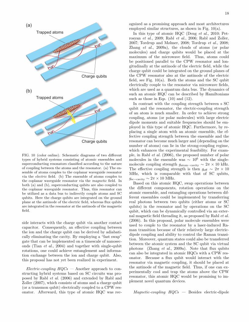
FIG. 10 (color online). Schematic diagrams of two differenttypes of hybrid systems consisting of atomic ensembles andsuperconducting resonators classified according to the natureof coupling between the atoms and the resonator. (a) The en-semble of atoms couples to the coplanar waveguide resonatorvia the electric field. (b) The ensemble of atoms couples tothe coplanar waveguide resonator via the magnetic field. Inboth (a) and (b), superconducting qubits are also coupled tothe coplanar waveguide resonator. Thus, this resonator canbe utilized as a data bus to indirectly couple atoms and SCqubits. Here the charge qubits are integrated on the groundplane at the antinode of the electric field, whereas flux qubitsare integrated in the resonator at the antinode of the magneticfield.
side interacts with the charge qubit via another contactcapacitor. Consequently, an effective coupling betweenthe ion and the charge qubit can be derived by adiabati-cally eliminating the cavity. By employing a “fast swap”gate that can be implemented on a timescale of nanosec-onds (Tian et al., 2004) and together with single-qubitrotations, one could achieve entanglement and informa-tion exchange between the ion and charge qubit. Also,this proposal has not yet been realized in experiment.
Electric-coupling HQCs — Another approach to con-structing hybrid systems based on SC circuits was pro-posed by Rabl et al. (2006) and extended by Rabl andZoller (2007), which consists of atoms and a charge qubit(or a transmon qubit) electrically coupled to a CPW res-onator. Afterward, this type of atomic HQC was rec-
ognized as a promising approach and most architecturesemployed similar structures, as shown in Fig. 10(a).
In this type of atomic HQC (Deng et al., 2010; Pet-rosyan et al., 2009; Rabl et al., 2006; Rabl and Zoller,2007; Tordrup and Mølmer, 2008; Tordrup et al., 2008;Zhang et al., 2009a), the clouds of atoms (or polarmolecules) and charge qubits would be placed at themaximum of the microwave field. Thus, atoms couldbe positioned parallel to the CPW resonator and lon-gitudinally at the antinode of the electric field, while thecharge qubit could be integrated on the ground planes ofthe CPW resonator also at the antinode of the electricfield, see Fig. 10(a). Both the atoms and the SC qubitelectrically couple to the resonator via microwave fields,which are used as a quantum data bus. The dynamics ofsuch an atomic HQC can be described by Hamiltonianssuch as those in Eqs. (10) and (12).
In contrast with the coupling strength between s SCqubit and the resonator, the electric-coupling strengthof an atom is much smaller. In order to achieve strongcoupling, atoms (or polar molecules) with large electricdipole moments and suitable frequencies should be em-ployed in this type of atomic HQC. Furthermore, by re-placing a single atom with an atomic ensemble, the ef-fective coupling strength between the ensemble and theresonator can become much larger and (depending on thenumber of atoms) can lie in the strong-coupling regime,which enhances the experimental feasibility. For exam-ple, in Rabl et al. (2006), the proposed number of polarmolecules in the ensemble was ∼ 106 with the single-molecule coupling strength gatom−cavity ∼ 2π × 10 kHz.The effective coupling strength is then geff ∼ 2π × 10MHz, which is comparable with that of SC qubits,gsc−cavity ∼ 2π × 10 MHz.
Based on this atomic HQC, swap operations betweenthe different components, rotation operations on theatomic ensemble, and entangling operations between dif-ferent ensembles could be implemented by transferringreal photons between two qubits (either atoms or SCqubits) in the resonator and by operations on the SCqubit, which can be dynamically controlled via an exter-nal magnetic field threading it, as proposed by Rabl et al.(2006). In this proposal, polar molecule ensembles wereused to couple to the resonator by a laser-induced Ra-man transition because of their relatively large electric-dipole coupling and ability to control the Raman transi-tion. Moreover, quantum states could also be transferredbetween the atomic system and the SC qubit via virtualphotons (Zhang et al., 2009a). Note that flux qubitscan also be integrated in atomic HQCs with a CPW res-onator. Because a flux qubit would interact with theresonator via magnetic coupling, it should be placed atthe antinode of the magnetic field. Thus, if one can ex-perimentally cool and trap the atoms above the CPWresonator, this atomic HQC would be promising to im-plement novel quantum devices.
Magnetic-coupling HQCs — Besides electric-dipole

19
coupling, the magnetic dipole moment can also be usedto couple atoms to a CPW resonator, while chargequbits electrically couple to the resonator, as shown inFig. 10(b). In this type of atomic HQC, the atoms wouldbe trapped above and parallel to the CPW resonator atan antinode of the magnetic field between the SC wireand ground planes, and the charge qubit would be inte-grated on the ground planes at an antinode of the electricfield.
For example, Verdu et al. (2009) theoretically consid-ered employing a hyperfine transition (at a frequency 6.83GHz) of 87Rb atoms, which constitute the atomic ensem-ble in the HQC. In this proposal, the 87Rb atoms wouldbe positioned slightly above the gap between the SC wireand the ground planes of the CPW resonator, where themagnetic field is strongest. The dynamics of the inter-action between the atoms and the resonator can be de-scribed by a Hamiltonian of the form given in Eq. (12).Consequently, the quantum state could be transferred be-tween the atomic ensemble and the resonator. Further-more, by integrating a SC qubit into the system, thisarchitecture could also implement various quantum gateoperations as in the electric-coupling atomic HQCs.
The magnetic coupling between atoms and the res-onator can effectively reduce the effect of charge noise inthe system. However, the magnetic-coupling strength isstill not sufficiently larger [about 40 kHz in Verdu et al.(2009)] than the decay rate κ/2π ∼ 7 kHz of the res-onator. Thus, it is necessary to increase the resonator’squality factor Q and thereby decrease the photon lossrate.
Rydberg atoms in HQCs — Rydberg atoms possess-ing large electric dipole moments and suitable frequen-cies can also be used in atomic HQCs with SC qubits.For instance, the proposal of Petrosyan et al. (2009) in-volving a similar structure of the SC circuit as in Rablet al. (2006) [see Fig. 10(a)] employed Rydberg states of87Rb atoms as the memory of the atomic HQC.
In this proposal, the charge qubit, possessing a largecoupling strength and good tunability, was used in thecircuit. On the atomic system side, the Rydberg states of87Rb atoms (|m〉 and |r〉) [see Fig. 11(a)] were used to in-teract with the electric field in the resonator. By makinga rotating-frame transformation, the coupling betweenRydberg atoms and the CPW resonator can be describedby the Hamiltonian:
Hac = h∆mgm†m+ h(∆mg + ∆rm)r†r
−h(Ωgmm†g + gacr
†ma+H.c.), (17)
where ∆mg (∆rm) is the detuning between the frequencyof an applied field (the photon in the resonator) andthe energy difference of the atomic transition |g〉 ↔ |m〉(|m〉 ↔ |r〉) (∆rm ' −∆mg = ∆ in this proposal), seeFig. 11(a). The operators m (m†), r (r†), and g (g†)annihilate (create) an atom in state |m〉, |r〉, and |g〉,respectively, and a (a†) is the photon annihilation (cre-ation) operator. The Rabi frequency of this applied laser
(a)
−∆mg ∆rm
Ωrs
Ωgm
(b)
∆
δ
ΩMWg
gac Ω1, k1
Ω2, k2,i
|g〉
|s〉
|m〉
|r〉 |eel〉
|e〉
|m〉
|g〉
|f〉
Ωrs
FIG. 11 (color online). Level structure, driving lasers (withRabi frequencies Ωgm, Ωrs, ΩMW , Ω1, and Ω2), and relevantcouplings (with coupling stregths gac and g) to microwavephotons in (a) (Petrosyan et al., 2009) model; (b) (Tordrupet al., 2008) model. (a) and (b) are adapted from (Petrosyanet al., 2009) and (Tordrup et al., 2008).
field and the coupling strength of the resonator’s photonwith the atom are Ωgm and gac, respectively. When aphoton is generated in the resonator, the laser field andthe photon would excite the atoms from the ground state|g〉 to the Rydberg state |r〉 via a nonresonant intermedi-ate Rydberg state |m〉, which is a two-photon transition.In the regime when ∆mg gac,Ωgm, the population ofstate |m〉 can be neglected, and the transition betweenstates |g〉 and |r〉 is described by
Vgr = hgeff(r†ga+ a†g†r) (18)
with geff = Ωgmgac/∆. Then, by introducing anotherlaser field with Rabi frequency Ωrs, the atoms can betransferred from the Rydberg state |r〉 to the storagestate |s〉 via a two-photon transition.
Thus, the process of transferring a quantum state fromthe SC qubit to this type of Rydberg atoms could be im-plemented as follows: First, the charge qubit is broughtto resonance with the CPW resonator for a duration oftime τSC = π/(2gSC) (SC qubit → resonator); next, thelaser field with Ωgi is turned on for a time duration
τgr = π/(2√Ngeff) (resonator → Rydberg state |r〉 of
atoms); finally, the laser field with Ωrs is switched onfor a time duration τrs = π/(2Ωrs) (Rydberg state |r〉 ofatoms → storage state |s〉). A similar sequence can beused for the opposite process.
The operation times [τgr, τrs ' 1 µs in Petrosyanet al. (2009)] are much smaller than the relative decaytimes in this atomic HQC, and the quantum informa-tion could therefore be transferred between the SC andatomic qubits. However, auxiliary optical fields can alsobe absorbed by the SC electrodes of the CPW resonatorbefore driving the atomic transition. A thin metallic mir-ror can be added to cover the SC electrodes as designed inPetrosyan et al. (2009), but reductions in the resonator’squality factor Q and the fidelity of the system may occur.This is a problem that should also be solved.

20
Many-qubit storage and computation — In addition tosingle-channel information processing, atomic HQCs can,in principle, be used for many-qubit storage and compu-tation. Tordrup and Mølmer (2008) and Tordrup et al.(2008) proposed two theoretical methods to achieve thispurpose by using an atomic HQC containing an ensembleof polar molecules and a charge qubit.
Tordrup and Mølmer (2008) proposed to store qubitstates in different rotational excited states of the molec-ular ensemble by using Raman transitions. Tordrupet al. (2008) proposed to store qubit states in differentcollective-excitation modes of plane-wave form. In bothof these proposals, quantum gate operations are imple-mented using an integrated charge qubit.
The proposed storage and retrieval method used inTordrup et al. (2008) is similar to some of the ideasthat are being pursued in more recent proposals and ex-periments, and we explain it in more detail. In addi-tion to two hyperfine rotational ground states |g〉 and|f〉 for qubit storage, an auxiliary rotational groundstate |m〉 and two rotationally and electronically ex-cited states |e〉 and |eel〉 are utilized, as shown inFig. 11(b). The storage process can be described as fol-lows: First, the information is stored in the auxiliarycollective state |m, 0〉 = (1/
√N)∑
i |g1 · · ·mi · · · gN 〉 viaa Raman transition; then through a stimulated Ramanadiabatic passage process with classical optical fields,the information is transferred to the collective state|f, ~qi〉 = (1/
√N)∑
i ei~qi·~xi |g1 · · · fi · · · gN 〉, with momen-
tum ~qi = ~k1 − ~k2,i. The dynamics of this process isdescribed by the Hamiltonian:
H =∑i
(Ω1e
i~k1·~xi |eel,i〉〈mi|
+ Ω2ei~k2,i·~xi |eel,i〉〈fi|+H.c.
), (19)
where Ω1 expi~k1 ·~xi and Ω2 expi~k2,i ·~xi describe twoclassical optical fields. The interaction in the above equa-tion could be used to encode a pattern expi~qi ·~xi in thecollective state |f, ~qi〉 from the auxiliary collective state|m, 0〉. The retrieval process could be implemented byreversing the storage procedure. By employing appropri-ate encoding methods of storing and retrieving quantuminformation as introduced in Tordrup et al. (2008), inprinciple, many-qubit storage could be implemented insuch a circuit.
To perform a single-qubit operation in the SC circuit,the relevant state should be transferred to the SC qubitthrough the CPW resonator. Two-qubit gates could alsobe realized by transferring one state to the SC qubit andanother to the resonator first, and then operating on thestate via the interaction between the SC qubit and theCPW resonator.
(a)(a)
(c)
(b)
Charge qubits
Trapped spins
Spins doped in
the substrate
Charge qubits
Charge qubits
Impurity spins
FIG. 12 (color online). Schematic diagrams of three types ofhybrid systems combining ensembles of spins and supercon-ducting resonators. (a) The ensemble of spin-carrying atomsis trapped using electromagnetic fields. (b) The ensemble ofspins is doped on the surface of the substrate of the super-conducting resonator. (c) The ensemble of spins is fixed ina sample of diamond or ruby that is placed on top of thesuperconducting wire of the resonator. As in Fig. 10, super-conducting qubits are also coupled to the coplanar waveguideresonator, so the resonator can be used as a data bus to indi-rectly couple the spins and SC qubits.
2. Spin hybrid quantum circuits
Facing the challenge of improving cooling and trappingtechniques required for atomic HQC, the focus recentlyshifted to ensembles of spins, as shown in Fig. 12, whichcan also serve as quantum memories with long coher-
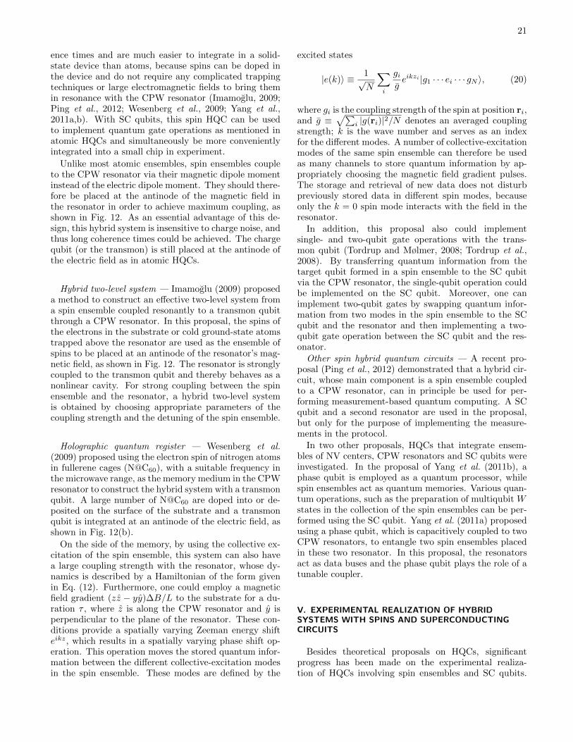
21
ence times and are much easier to integrate in a solid-state device than atoms, because spins can be doped inthe device and do not require any complicated trappingtechniques or large electromagnetic fields to bring themin resonance with the CPW resonator (Imamoglu, 2009;Ping et al., 2012; Wesenberg et al., 2009; Yang et al.,2011a,b). With SC qubits, this spin HQC can be usedto implement quantum gate operations as mentioned inatomic HQCs and simultaneously be more convenientlyintegrated into a small chip in experiment.
Unlike most atomic ensembles, spin ensembles coupleto the CPW resonator via their magnetic dipole momentinstead of the electric dipole moment. They should there-fore be placed at the antinode of the magnetic field inthe resonator in order to achieve maximum coupling, asshown in Fig. 12. As an essential advantage of this de-sign, this hybrid system is insensitive to charge noise, andthus long coherence times could be achieved. The chargequbit (or the transmon) is still placed at the antinode ofthe electric field as in atomic HQCs.
Hybrid two-level system — Imamoglu (2009) proposeda method to construct an effective two-level system froma spin ensemble coupled resonantly to a transmon qubitthrough a CPW resonator. In this proposal, the spins ofthe electrons in the substrate or cold ground-state atomstrapped above the resonator are used as the ensemble ofspins to be placed at an antinode of the resonator’s mag-netic field, as shown in Fig. 12. The resonator is stronglycoupled to the transmon qubit and thereby behaves as anonlinear cavity. For strong coupling between the spinensemble and the resonator, a hybrid two-level systemis obtained by choosing appropriate parameters of thecoupling strength and the detuning of the spin ensemble.
Holographic quantum register — Wesenberg et al.(2009) proposed using the electron spin of nitrogen atomsin fullerene cages (N@C60), with a suitable frequency inthe microwave range, as the memory medium in the CPWresonator to construct the hybrid system with a transmonqubit. A large number of N@C60 are doped into or de-posited on the surface of the substrate and a transmonqubit is integrated at an antinode of the electric field, asshown in Fig. 12(b).
On the side of the memory, by using the collective ex-citation of the spin ensemble, this system can also havea large coupling strength with the resonator, whose dy-namics is described by a Hamiltonian of the form givenin Eq. (12). Furthermore, one could employ a magneticfield gradient (zz − yy)∆B/L to the substrate for a du-ration τ , where z is along the CPW resonator and y isperpendicular to the plane of the resonator. These con-ditions provide a spatially varying Zeeman energy shifteikz, which results in a spatially varying phase shift op-eration. This operation moves the stored quantum infor-mation between the different collective-excitation modesin the spin ensemble. These modes are defined by the
excited states
|e(k)〉 ≡ 1√N
∑i
gigeikzi |g1 · · · ei · · · gN 〉, (20)
where gi is the coupling strength of the spin at position ri,and g ≡
√∑i |g(ri)|2/N denotes an averaged coupling
strength; k is the wave number and serves as an indexfor the different modes. A number of collective-excitationmodes of the same spin ensemble can therefore be usedas many channels to store quantum information by ap-propriately choosing the magnetic field gradient pulses.The storage and retrieval of new data does not disturbpreviously stored data in different spin modes, becauseonly the k = 0 spin mode interacts with the field in theresonator.
In addition, this proposal also could implementsingle- and two-qubit gate operations with the trans-mon qubit (Tordrup and Mølmer, 2008; Tordrup et al.,2008). By transferring quantum information from thetarget qubit formed in a spin ensemble to the SC qubitvia the CPW resonator, the single-qubit operation couldbe implemented on the SC qubit. Moreover, one canimplement two-qubit gates by swapping quantum infor-mation from two modes in the spin ensemble to the SCqubit and the resonator and then implementing a two-qubit gate operation between the SC qubit and the res-onator.Other spin hybrid quantum circuits — A recent pro-
posal (Ping et al., 2012) demonstrated that a hybrid cir-cuit, whose main component is a spin ensemble coupledto a CPW resonator, can in principle be used for per-forming measurement-based quantum computing. A SCqubit and a second resonator are used in the proposal,but only for the purpose of implementing the measure-ments in the protocol.
In two other proposals, HQCs that integrate ensem-bles of NV centers, CPW resonators and SC qubits wereinvestigated. In the proposal of Yang et al. (2011b), aphase qubit is employed as a quantum processor, whilespin ensembles act as quantum memories. Various quan-tum operations, such as the preparation of multiqubit Wstates in the collection of the spin ensembles can be per-formed using the SC qubit. Yang et al. (2011a) proposedusing a phase qubit, which is capacitively coupled to twoCPW resonators, to entangle two spin ensembles placedin these two resonator. In this proposal, the resonatorsact as data buses and the phase qubit plays the role of atunable coupler.
V. EXPERIMENTAL REALIZATION OF HYBRIDSYSTEMS WITH SPINS AND SUPERCONDUCTINGCIRCUITS
Besides theoretical proposals on HQCs, significantprogress has been made on the experimental realiza-tion of HQCs involving spin ensembles and SC qubits.

22
(b)
(a)
Gap-tunable
flux qubit
NV centers
Readout
d.c. SQUID
FIG. 13 (color online). (a) Sketch of the experimental setupin Zhu et al. (2011). A diamond crystal (an ensemble of NVcenters) was glued on top of a superconducting circuit, wherea gap-tunable flux qubit [shown in (b)] (two small loops in thecenter) and a readout dc SQUID (the largest loop) shared acommon edge. (b) Circuit diagram of the gap-tunable fluxqubit used in the central part of the superconducting circuitshown in (a).
A strong coupling between spin ensembles and SC res-onators was achieved first. Afterwards, a direct-couplinghybrid circuit (NV centers and a flux qubit) as well as anindirect-coupling hybrid circuit (NV centers and a trans-mon qubit in a SC resonator) were also experimentallyrealized.
A. Direct-coupling hybrid circuit with nitrogen-vacancycenters and a flux qubit
The theoretical proposal studied by Marcos et al.(2010) (see Sec. IV.C) was recently realized experimen-tally (Zhu et al., 2011). In this experiment, a sample ofdiamond containing ∼ 3 × 10⁷ NV centers was glued ontop of the SC circuit [Fig. 13(a)], which consisted of a fluxqubit [Fig. 13(b)] and a readout dc SQUID [the largestloop in Fig. 13(a)] inductively coupled to the qubit. Forbetter tunability, they used a low-inductance dc SQUIDloop to replace the smallest of the three Josephson junc-tions in the flux qubit. Thus, by controlling the magneticfluxes threading the main loop of the flux qubit [the left,big loop in Fig. 13(b)] and the small loop of the d.c.SQUID [the right, small loop in Fig. 13(b)], the energysplitting of the flux qubit can be adjusted. Note that thisexperiment differed from the proposal of Marcos et al.(2010) in that the states |ms = ±1〉 of NV centers werenot split by the weak external field, but rather hybridizedby the strain-induced field. As a result, a superpositionof these two states is involved in the coupling to the fluxqubit.
From the spectroscopic measurements of the flux qubitcoupled to the spin ensemble, a vacuum Rabi splittingwas observed and the coupling strength between the twosystems reached 70 MHz. Thus, this direct-couplingHQC could be used to transfer quantum information be-tween the two components. By tuning the flux qubit intoresonance with the spin ensemble, single-energy-quantumexchange between the two systems was observed with thedecay time ∼ 20 ns.
The most likely sources of decoherence are the largeelectron-spin bath of P1 centers (a nitrogen atom sub-stituting a carbon atom), which are generated whenthe sample is prepared. Because the two types of elec-tron spins naturally couple to each other in the experi-ment (Zhu et al., 2011), applying an external magneticfield to change the energy gap of NV centers or using abetter sample could effectively improve the decay time ofthe NV center ensemble. Another source of decoherenceis the strong hyperfine interaction between the NV cen-ter spins and 13C nuclear spins, which is approximately100 MHz. This source of decay might be reduced by po-larizing the nuclear spins. Therefore, in principle, thedecoherence can be reduced and better direct-couplingHQCs can be experimentally realized.
B. Spins coupled to superconducting resonators (withoutqubits)
In order to achieve an indirectly-coupled HQC, onehas to have a strong coupling between the SC resonatorand both the SC qubit and the spin ensemble. Sev-eral experiments demonstrated the possibility to strongly,even ultrastrongly, couple SC qubits with resonators (De-voret et al., 2007; Hofheinz et al., 2009, 2008; Niem-czyk et al., 2010; Sillanpaa et al., 2007; Wallraff et al.,2004). However, similar experiments on spin ensem-bles have not been implemented until recently and thesehave become the first challenge to experimentally realiz-ing HQCs. Note that semiconductor quantum dots havealso been experimentally integrated into superconductingresonators (Frey et al., 2012); however, their coherencetimes are much shorter than impurity spins.
Recently, four independent groups experimentallyachieved strong coupling between an ensemble of impu-rity spins and a CPW resonator (Amsuss et al., 2011;Bushev et al., 2011; Kubo et al., 2012, 2010; Sandneret al., 2012; Schuster et al., 2010). They placed a solid-state ensemble of spins on the SC wire at an antinode ofthe standing wave of the current on the SC wire, wherethe resonator’s magnetic field has a maximum, as shownin Fig. 12(c). NV centers in diamond were used by Kuboet al. (2012, 2010), Amsuss et al. (2011), and Sandneret al. (2012), Cr3+ spins in ruby and P1 centers in dia-mond were utilized by Schuster et al. (2010), and Er3+
ions in a Y2SiO5 crystal were employed by Bushev et al.(2011). The frequencies of these impurity spins are allcompatible with those of SC resonators. In order to
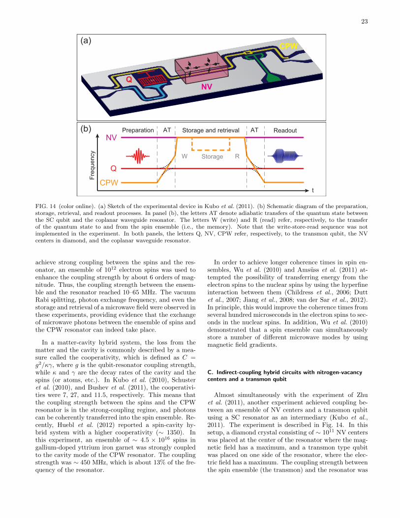
23
CPW
NVQ
(a)
NV
Q
CPW
(b)
Storage
ReadoutPreparation
t
Fre
que
ncy
W R
AT ATStorage and retrieval
FIG. 14 (color online). (a) Sketch of the experimental device in Kubo et al. (2011). (b) Schematic diagram of the preparation,storage, retrieval, and readout processes. In panel (b), the letters AT denote adiabatic transfers of the quantum state betweenthe SC qubit and the coplanar waveguide resonator. The letters W (write) and R (read) refer, respectively, to the transferof the quantum state to and from the spin ensemble (i.e., the memory). Note that the write-store-read sequence was notimplemented in the experiment. In both panels, the letters Q, NV, CPW refer, respectively, to the transmon qubit, the NVcenters in diamond, and the coplanar waveguide resonator.
achieve strong coupling between the spins and the res-onator, an ensemble of 1012 electron spins was used toenhance the coupling strength by about 6 orders of mag-nitude. Thus, the coupling strength between the ensem-ble and the resonator reached 10–65 MHz. The vacuumRabi splitting, photon exchange frequency, and even thestorage and retrieval of a microwave field were observed inthese experiments, providing evidence that the exchangeof microwave photons between the ensemble of spins andthe CPW resonator can indeed take place.
In a matter-cavity hybrid system, the loss from thematter and the cavity is commonly described by a mea-sure called the cooperativity, which is defined as C =g2/κγ, where g is the qubit-resonator coupling strength,while κ and γ are the decay rates of the cavity and thespins (or atoms, etc.). In Kubo et al. (2010), Schusteret al. (2010), and Bushev et al. (2011), the cooperativi-ties were 7, 27, and 11.5, respectively. This means thatthe coupling strength between the spins and the CPWresonator is in the strong-coupling regime, and photonscan be coherently transferred into the spin ensemble. Re-cently, Huebl et al. (2012) reported a spin-cavity hy-brid system with a higher cooperativity (∼ 1350). Inthis experiment, an ensemble of ∼ 4.5 × 10¹⁶ spins ingallium-doped yttrium iron garnet was strongly coupledto the cavity mode of the CPW resonator. The couplingstrength was ∼ 450 MHz, which is about 13% of the fre-quency of the resonator.
In order to achieve longer coherence times in spin en-sembles, Wu et al. (2010) and Amsuss et al. (2011) at-tempted the possibility of transferring energy from theelectron spins to the nuclear spins by using the hyperfineinteraction between them (Childress et al., 2006; Duttet al., 2007; Jiang et al., 2008; van der Sar et al., 2012).In principle, this would improve the coherence times fromseveral hundred microseconds in the electron spins to sec-onds in the nuclear spins. In addition, Wu et al. (2010)demonstrated that a spin ensemble can simultaneouslystore a number of different microwave modes by usingmagnetic field gradients.
C. Indirect-coupling hybrid circuits with nitrogen-vacancycenters and a transmon qubit
Almost simultaneously with the experiment of Zhuet al. (2011), another experiment achieved coupling be-tween an ensemble of NV centers and a transmon qubitusing a SC resonator as an intermediary (Kubo et al.,2011). The experiment is described in Fig. 14. In thissetup, a diamond crystal consisting of ∼ 1011 NV centerswas placed at the center of the resonator where the mag-netic field has a maximum, and a transmon type qubitwas placed on one side of the resonator, where the elec-tric field has a maximum. The coupling strength betweenthe spin ensemble (the transmon) and the resonator was

24
TABLE III Coupling strengths between resonators and other systems in different proposals and experiments.
Reference Atoms or spins Couplingmechanism
Number ofatoms or spins
Coupling toatoms or spins
Coupling toSC qubit
Cooper-ativitya
Theoretical Proposals
(Rabl et al., 2006) Molecules Electric 104–106 1–10 MHz <∼ 50 MHz > 103
(Tordrup et al., 2008) Atoms or Molecules Electric 105–106 1–10 MHz 200 MHz > 103
(Verdu et al., 2009) Atoms (87Rb) Magnetic ∼ 106 40 kHz 50 MHz 1.7
(Petrosyan et al., 2009) Rydberg atoms (87Rb) Electric ∼ 106 3.85 MHz 50 MHz 1.5× 10⁴
(Imamoglu, 2009) Spins Magnetic ∼ 108 10 MHz > 100 MHz 3.9× 10³
(Wesenberg et al., 2009) Spins (N@C60) Magnetic ∼ 1011 6 MHz ∼ 100 MHz > 4× 10²
Experiments
(Kubo et al., 2010) Spins (NV centers) Magnetic ∼ 1012 11.6 MHz — 27
(Schuster et al., 2010) Spins (Cr3+ or N) Magnetic ∼ 1012 65 MHz — 11.5
(Bushev et al., 2011) Spins (Er3+) Magnetic ∼ 1012 20 MHz — 7
(Amsuss et al., 2011) Spins (NV centers) Magnetic ∼ 1012 10 MHz — 10–20
(Kubo et al., 2011) Spins (NV centers) Magnetic ∼ 1011 3–4 MHz 7 MHz 15–20
aThe cooperativities listed here are for the coupling between aCPW resonator and either atoms or spins; for the coupling betweena CPW resonator and a SC qubit, the cooperativity is usually largerthan 103.
∼ 3 MHz (7.2 MHz).
In order to couple these two systems with different fre-quencies, a tunable CPW resonator was used. In thisresonator, a SQUID was embedded in order to make thefrequency of the resonator tunable (through its depen-dence on the applied magnetic flux threading the SQUIDloop). Thus, storage, readout and transfer of quantuminformation can be achieved by tuning the frequency ofthe resonator into resonance with the SC qubit and thespin ensemble. In the experiment, these processes wereexperimentally realized as follows [Fig. 14(b)]: First, af-ter preparing a quantum state in the SC qubit, the fre-quency of the resonator was adiabatically swept acrossthe frequency of the qubit, transferring the qubit stateto the corresponding photonic state. This process is moreimmune to flux noise in the SQUID than putting the twosystems in resonance for a carefully set duration (Weiet al., 2008). The frequency of the resonator was thenbrought into resonance with the spin ensemble for someduration. The quantum state then oscillates between theresonator and the spin ensemble. The frequency of theresonator was then tuned away from that of the spinensemble, and adiabatically swept across the frequencyof the qubit, transferring the photonics state of the res-onator to the SC qubit. Finally, the state of the SCqubit was measured. In principle, a storage and retrievalprocess could be implemented by adjusting the interac-
tion time between the resonator and the spin ensemble insuch a way to exactly swap the quantum state betweenthe two systems, as shown by the dashed line in Fig. 14.For technical reasons, however, this experiment was notperformed (Kubo, 2012).
However, in the presence of interference effects causedby the hyperfine structure of NV centers and the inho-mogeneous broadening at resonance, the fidelity, whichdescribes the correspondence of the readout signal withthe original signal, was very low (about 10%) and the co-herence times were not very long (about several hundrednanoseconds). Higher-purity diamond could greatly im-prove the performance of NV centers (long coherence).However, one has to keep in mind that a high concen-tration of spins is desirable for the purpose of achievingstrong coupling. Thus, one of the challenges at the mo-ment is to find the best compromise between high con-centration (strong coupling) and diluted impurities (longcoherence). There are also efforts aimed at finding meth-ods for enhancing the coherence of these systems, suchas dynamical decoupling (de Lange et al., 2010; Huanget al., 2011; Naydenov et al., 2011).
Table III lists some parameters, including couplingstrengths between different systems and CPW resonatorsand related cooperativities. These parameters are essen-tial for achieving an effective exchange of quantum in-

25
(a)
Φe
(b))
Φe(t)
(c)
Φe icia
Vg V
B||
FIG. 15 (color online). Schematic diagrams of hybrid quantum circuits consisting of nanomechanical resonators (representedby the solid and dashed lines) and (a) a superconducting charge qubit, (b) an rf-SQUID, and (c) a three-junction flux qubit.
formation between the quantum bus (the resonator) andboth the memory (the atoms or spins) and the processor(the SC qubits). All these results of combining atomicensembles (including spins) and CPW resonators to buildhybrid circuits point toward more progress in the future.
VI. HYBRID QUANTUM CIRCUITS WITHNANOMECHANICAL RESONATORS
There are three main approaches that have been con-sidered for coupling a SC qubit and a NAMR: via a neigh-boring capacitance [see Fig. 15(a)], by changing an ap-plied magnetic flux [see Fig. 15(b)], or via a Lorentz forceinduced by a loop current [see Fig. 15(c)].
Recently, many groups have devoted considerable ef-fort to this type of HQC. In such a HQC, the NAMRcan couple to a SC circuit and serve as a cavity. Theentire configuration thereby provides a solid-state ana-log of cavity-QED systems, and it can reach the strong-coupling regime (Schwab and Roukes, 2005). Meanwhile,the NAMRs are generally much smaller in size than CPWresonators, and thus they can be more easily integrated inhigh-density quantum devices. Various designs and ap-plications of quantum (or nonclassical) behavior in thistype of HQC have been studied, such as the generationof quantum entanglement (Armour et al., 2002; Clelandand Geller, 2004), quantum measurement (LaHaye et al.,2009), high precision displacement detection (Etaki et al.,2008), and cooling (Grajcar et al., 2008a; Taylor et al.,2011; Teufel et al., 2011; Wei et al., 2006; Xue et al.,2007b).
A. Coupling mechanisms
1. Capacitive coupling
In this case, the NAMR is capacitively coupled toa charge qubit via a capacitance that depends on thedisplacement x of the harmonic oscillator, as shown inFig. 15(a). The amplitude of the oscillation of the NAMRis much smaller than the equilibrium distance d between
the SC qubit and the NAMR. Thus, the capacitance be-tween them approximately becomes C(x) ' C0(1−x/d),where C0 is the capacitance of the NAMR in equilibrium.This x-dependent capacitance leads to a situation wherethe harmonic-oscillation mode of the NAMR effectivelycouples to the quantum state of the charge qubit.
2. Magnetic flux coupling
In this case, the NAMR is embedded in the loop ofan rf SQUID or a flux qubit and oscillates in the planeof the loop, as shown in Fig. 15(b). The displacementof the NAMR leads to a small change in the loop areaand therefore the magnetic flux ∆Φ = αBlx, where αis a geometric factor and l is the length of the can-tilever. The total magnetic flux threading the rf-SQUIDor the flux qubit becomes an x-dependent magnetic fluxΦe[x] = BA + αBlx = Φeq + ∆Φ[x], where Φeq is themagnetic flux when the cantilever is at its equilibriumposition and ∆Φ[x] = αBlx is the flux variation dueto the vibration of the cantilever. Because the SQUIDand the flux qubit are sensitive to the applied magneticflux, such an x-dependent magnetic flux can induce an ef-fective strong coupling between the quantized harmonic-oscillation mode of the NAMR and the quantum statesof the SQUID or the flux qubit.
3. Electromotive coupling
In this case, the NAMR is also embedded in the loopof a flux qubit, but oscillates along the direction perpen-dicular to the plane of the loop, as shown in Fig. 15(c).When an external magnetic field B‖ is applied parallel tothe plane of the loop, the persistent current can induce aLorentz force with opposite directions for the clockwiseand anticlockwise current states. Meanwhile, the oscil-lations of the NAMR are modulated by these Lorentzforces. Thus, the quantized harmonic-oscillation modeof the cantilever is coupled to the quantum state of theflux qubit.
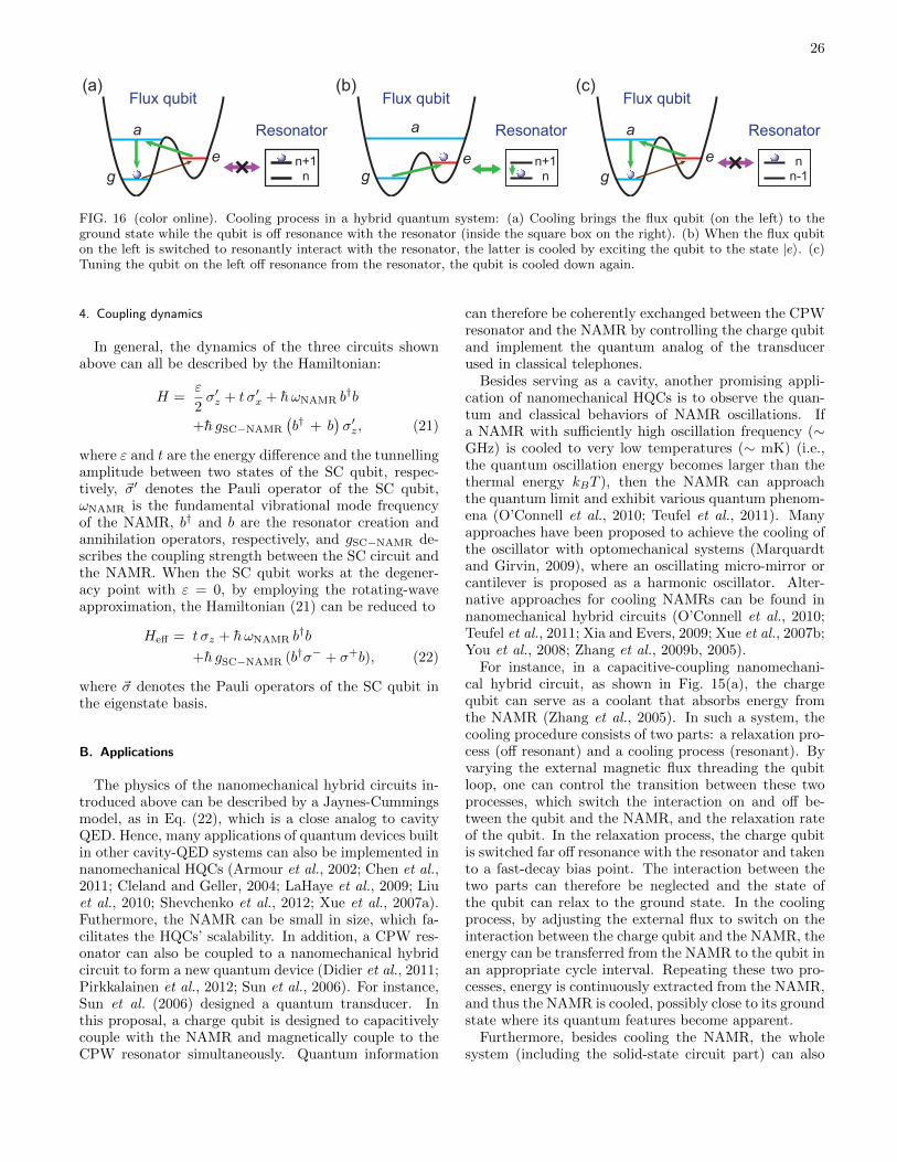
26
(a)
a
g
e
(b)
a
g
e
(c)
a
g
en+1n-1n
nn+1
n
Flux qubit
Resonator
Flux qubit
Resonator
Flux qubit
Resonator
FIG. 16 (color online). Cooling process in a hybrid quantum system: (a) Cooling brings the flux qubit (on the left) to theground state while the qubit is off resonance with the resonator (inside the square box on the right). (b) When the flux qubiton the left is switched to resonantly interact with the resonator, the latter is cooled by exciting the qubit to the state |e〉. (c)Tuning the qubit on the left off resonance from the resonator, the qubit is cooled down again.
4. Coupling dynamics
In general, the dynamics of the three circuits shownabove can all be described by the Hamiltonian:
H =ε
2σ′z + t σ′x + h ωNAMR b
†b
+h gSC−NAMR
(b† + b
)σ′z, (21)
where ε and t are the energy difference and the tunnellingamplitude between two states of the SC qubit, respec-tively, ~σ′ denotes the Pauli operator of the SC qubit,ωNAMR is the fundamental vibrational mode frequencyof the NAMR, b† and b are the resonator creation andannihilation operators, respectively, and gSC−NAMR de-scribes the coupling strength between the SC circuit andthe NAMR. When the SC qubit works at the degener-acy point with ε = 0, by employing the rotating-waveapproximation, the Hamiltonian (21) can be reduced to
Heff = t σz + h ωNAMR b†b
+h gSC−NAMR (b†σ− + σ+b), (22)
where ~σ denotes the Pauli operators of the SC qubit inthe eigenstate basis.
B. Applications
The physics of the nanomechanical hybrid circuits in-troduced above can be described by a Jaynes-Cummingsmodel, as in Eq. (22), which is a close analog to cavityQED. Hence, many applications of quantum devices builtin other cavity-QED systems can also be implemented innanomechanical HQCs (Armour et al., 2002; Chen et al.,2011; Cleland and Geller, 2004; LaHaye et al., 2009; Liuet al., 2010; Shevchenko et al., 2012; Xue et al., 2007a).Futhermore, the NAMR can be small in size, which fa-cilitates the HQCs’ scalability. In addition, a CPW res-onator can also be coupled to a nanomechanical hybridcircuit to form a new quantum device (Didier et al., 2011;Pirkkalainen et al., 2012; Sun et al., 2006). For instance,Sun et al. (2006) designed a quantum transducer. Inthis proposal, a charge qubit is designed to capacitivelycouple with the NAMR and magnetically couple to theCPW resonator simultaneously. Quantum information
can therefore be coherently exchanged between the CPWresonator and the NAMR by controlling the charge qubitand implement the quantum analog of the transducerused in classical telephones.
Besides serving as a cavity, another promising appli-cation of nanomechanical HQCs is to observe the quan-tum and classical behaviors of NAMR oscillations. Ifa NAMR with sufficiently high oscillation frequency (∼GHz) is cooled to very low temperatures (∼ mK) (i.e.,the quantum oscillation energy becomes larger than thethermal energy kBT ), then the NAMR can approachthe quantum limit and exhibit various quantum phenom-ena (O’Connell et al., 2010; Teufel et al., 2011). Manyapproaches have been proposed to achieve the cooling ofthe oscillator with optomechanical systems (Marquardtand Girvin, 2009), where an oscillating micro-mirror orcantilever is proposed as a harmonic oscillator. Alter-native approaches for cooling NAMRs can be found innanomechanical hybrid circuits (O’Connell et al., 2010;Teufel et al., 2011; Xia and Evers, 2009; Xue et al., 2007b;You et al., 2008; Zhang et al., 2009b, 2005).
For instance, in a capacitive-coupling nanomechani-cal hybrid circuit, as shown in Fig. 15(a), the chargequbit can serve as a coolant that absorbs energy fromthe NAMR (Zhang et al., 2005). In such a system, thecooling procedure consists of two parts: a relaxation pro-cess (off resonant) and a cooling process (resonant). Byvarying the external magnetic flux threading the qubitloop, one can control the transition between these twoprocesses, which switch the interaction on and off be-tween the qubit and the NAMR, and the relaxation rateof the qubit. In the relaxation process, the charge qubitis switched far off resonance with the resonator and takento a fast-decay bias point. The interaction between thetwo parts can therefore be neglected and the state ofthe qubit can relax to the ground state. In the coolingprocess, by adjusting the external flux to switch on theinteraction between the charge qubit and the NAMR, theenergy can be transferred from the NAMR to the qubit inan appropriate cycle interval. Repeating these two pro-cesses, energy is continuously extracted from the NAMR,and thus the NAMR is cooled, possibly close to its groundstate where its quantum features become apparent.
Furthermore, besides cooling the NAMR, the wholesystem (including the solid-state circuit part) can also
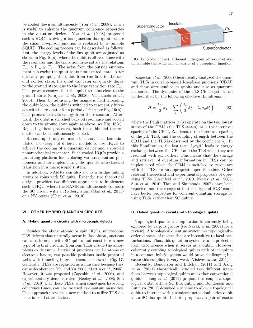
27
be cooled down simultaneously (You et al., 2008), whichis useful to enhance the quantum coherence propertiesin the quantum device. You et al. (2008) proposedsuch a HQC involving a four-junction flux qubit, wherethe small Josephson junction is replaced by a tunableSQUID. The cooling process can be described as follows:first, the energy levels of the flux qubit are adjusted asshown in Fig. 16(a), where the qubit is off resonance withthe resonator and the transition rates satisfy the relationsΓag > Γea Γge. The noise from the outside environ-ment can excite the qubit to its first excited state. Afteroptically pumping the qubit from the first to the sec-ond excited state, the qubit can later on quickly decayto the ground state, due to the large transition rate Γag.This process ensures that the qubit remains close to theground state (Grajcar et al., 2008b; Valenzuela et al.,2006). Then, by adjusting the magnetic field threadingthe qubit loop, the qubit is switched to resonantly inter-act with the resonator for a period of time [see Fig. 16(b)].This process extracts energy from the resonator. After-ward, the qubit is switched back off resonance and cooleddown to the ground state again as above [see Fig. 16(c)].Repeating these processes, both the qubit and the res-onator can be simultaneously cooled.
Recent rapid progress made in nanoscience has stim-ulated the design of different models to use HQCs toachieve the cooling of a quantum device and a couplednanomechanical resonator. Such cooled HQCs provide apromising platform for exploring various quantum phe-nomena and for implementing the quantum-to-classicaltransition in a macroscopic system.
In addition, NAMRs can also act as a bridge linkingatoms or spins with SC quits. Recently, two theoreticaldesigns provided two different approaches to implementsuch a HQC, where the NAMR simultaneously connectsthe SC circuit with a Rydberg atom (Gao et al., 2011)or a NV center (Chen et al., 2010).
VII. OTHER HYBRID QUANTUM CIRCUITS
A. Hybrid quantum circuits with microscopic defects
Besides the above atomic or spin HQCs, microscopicTLS defects that naturally occur in Josephson junctionscan also interact with SC qubits and constitute a newtype of hybrid circuits. Spurious TLSs inside the amor-phous oxide tunnel barrier of junctions can be atoms orelectrons having two possible positions inside potentialwells with tunneling between them, as shown in Fig. 17.Generally, TLSs are regarded as a nuisance because theycause decoherence (Ku and Yu, 2005; Martin et al., 2005).However, it was proposed (Zagoskin et al., 2006), andexperimentally demonstrated (Neeley et al., 2008; Sunet al., 2010) that these TLSs, which sometimes have longcoherence times, can also be used as quantum memories.This approach provides a new method to utilize TLS de-fects in solid-state devices.
I(t)Superconductor
Insulator
Superconductor
ISuperconductor
Insulator
Superconduct
FIG. 17 (color online). Schematic diagram of two-level sys-tems inside the oxide tunnel barrier of a Josephson junction.
Zagoskin et al. (2006) theoretically analyzed the quan-tum TLSs in current-biased Josephson junctions (CBJJ)and these were studied as qubits and also as quantummemories. The dynamics of the TLS-CBJJ system canbe described by the following effective Hamiltonian:
H =hω
2σz +
∑j
(∆j
2σjz + λjσxσ
jx
), (23)
where the Pauli matrices ~σ (~σ) operate on the two loweststates of the CBJJ (the TLS states), ω is the interlevelspacing of the CBJJ, ∆j denotes the interlevel spacingof the jth TLS, and the coupling strength between theCBJJ and the TLS is described by the coefficient λj . Inthis Hamiltonian, the last term λjσxσ
jx leads to energy
exchange between the CBJJ and the TLS when they areresonant with each other. This means that the storageand retrieval of quantum information in TLSs can beimplemented when the CBJJ is switched to resonancewith the TLSs for an appropriate operation time. Otherrelevant theoretical and experimental proposals of oper-ating TLSs (Lisenfeld et al., 2010; Neeley et al., 2008;Sun et al., 2010; Tian and Simmonds, 2007) have beenreported, and these suggest that this type of HQC couldhave better properties for coherent quantum storage byusing TLSs rather than SC qubits.
B. Hybrid quantum circuits with topological qubits
Topological quantum computation is currently beingexplored by various groups [see Nayak et al. (2008) for areview]. A topological quantum system has topologically-ordered states of matter that are insensitive to local per-turbations. Thus, this quantum system can be protectedfrom decoherence when it serves as a qubit. However,coherently coupling topological qubits with other qubitsin a common hybrid system would prove challenging be-cause this coupling is very weak (Vishveshwara, 2011).
Recently, Bonderson and Lutchyn (2011) and Jianget al. (2011) theoretically studied two different inter-faces between topological qubits and other conventionalqubits. Jiang et al. (2011) proposed to couple a topo-logical qubit with a SC flux qubit, and Bonderson andLutchyn (2011) designed a scheme to allow a topologicalqubit to interact with a semiconductor double-dot qubitvia a SC flux qubit. In both proposals, a pair of exotic
28
quasiparticles (Majorana fermions) was used as the topo-logical qubit, and was localized on the segments formedby a topological insulator (Jiang et al., 2011), or on awire whose conduction electrons have strong spin-orbitcoupling (Bonderson and Lutchyn, 2011). The Majoranafermion is an exotic particle which is its own antiparticle.This pair of Majorana fermions is in a nonlocal quan-tum state and possesses non-Abelian quantum statistics,which are crucial for topological quantum computation.
Jiang et al. (2011) theoretically considered the prox-imity effect (Tinkham, 1996) to link the macroscopicwave function of the superconductor with the Majoranafermions at the interface between the superconductor andtopological insulator via the tunneling of Cooper pairsbetween these two materials (Fu and Kane, 2008). Con-sequently, the superconducting phase, which depends onthe state of the flux qubit, can coherently control theMajorana fermions in the topological qubit and be de-signed as a key ingredient of controlled-phase gate toachieve the exchange of quantum information betweenthe SC qubit and the topological qubit. Bonderson andLutchyn (2011) theoretically considered the Aharonov-Casher effect to effectively couple the topological qubitto a double quantum dot qubit (Hanson and Awschalom,2008a). The Aharonov-Casher effect is dual to the famil-iar Aharonov-Bohm effect, and it states that a neutralparticle possessing a magnetic moment, such as a vortexin a superconductor, can obtain a quantum phase shiftwhile moving around a line charge. When the Majoranafermion pair and quantum dots are placed on the fluxqubit, the Aharonov-Casher effect makes the state of theflux qubit sensitive to the electron parity of the Majo-rana fermion pair and quantum dots. Thus, the paritymeasurements with the help of the flux qubit could beused to entangle qubits and coherently transfer quantuminformation.
Moreover, a method to coherently transfer quantuminformation and perform other quantum operations ontopological qubits and spins in quantum dots was alsotheoretically proposed recently (Leijnse and Flensberg,2011, 2012).
C. Hybrid quantum circuits for converting optical photonsto microwave photons
Most proposals and experiments introduced above in-volve microwave photons in the GHz frequency range.However, there are many quantum systems working inthe visible or infrared frequency range. Recently, DiVin-cenzo et al. (2011) proposed a hybrid superconductor-optical quantum repeater which integrates an optical sys-tem of a visible or infrared frequency with a SC circuitin the GHz range. In this quantum repeater, the SC andoptical subsystems couple to each other via a microwavetransmission medium, such as a CPW. The process ofexchanging a quantum state between them could be im-plemented as follows: First in the optical subsystem, a
photon is received and transferred via an optical chan-nel. Then it is downconverted to a microwave photon inthe microwave transmission medium. Finally the quan-tum signal is transferred from the microwave photon andstored or operated on the SC qubit. This process canalso be applied in the opposite direction.
In such a HQC, the key issue in transferring the quan-tum signal between optical and SC subsystems is thedown-conversion process of the optical photon to themicrowave photon, and the inverse process (i.e., up-conversion) (Strekalov et al., 2009). DiVincenzo et al.(2011) proposed using a nanoscale tunnel junction, whichhas a nonlinear current-to-voltage characteristic, to linkthe optical and microwave signals. This nonlinear tun-nel junction can convert the optical power to a currentsource as
I(ω = 0) = ηE(ωopt)E∗(ωopt), (24)
where I(ω = 0) is the output dc current, η is the efficiencycoefficient, and E(ωopt) the electric field at the tunneljunction, which has a frequency ωopt. In the downcon-version process, there are two optical fields introduced atthe junction. One is the signal photon from the opticalsubsystem with frequency ωopt + ∆ω, and the other isthe strong laser beam with frequency ωopt. The outputcurrent produced by the nonlinear junction is I(∆ω) =ηE(ωopt)E
∗(ωopt + ∆ω), where ∆ω can be in the GHzrange, matching the working frequency of a SC subsys-tem. As a result, quantum information carried in theoptical photon can be converted to a current signal withGHz frequency and then transferred as a microwave pho-ton in the microwave transmission medium. In the oppo-site process, the output current produced by the nonlin-ear junction becomes I(ωopt + ∆ω) = ηE(ωopt)E
∗(∆ω),and the microwave photon can then be up-converted tothe optical photon. For other related work, see Ilchenkoet al. (2003), Matsko et al. (2007), Tsang (2010), Tsang(2011), Wang and Clerk (2012), and Tian (2012).
VIII. DISCUSSION AND CONCLUSION
Hybrid quantum circuits promise to open up new pos-sibilities for quantum technologies where the hybrid cir-cuit combines the best features of its constituents, suchas long coherence times, fast operations and scalability.
We presented an overview of the current status ofHQCs, especially devices integrating atomic or spin sys-tems with SC qubits or resonators, where considerableprogress has been made recently in both theory and ex-periment.
Even though the basic ideas for coupling the differentsystems together (e.g., relying on the natural coupling toelectric or magnetic fields) are quite simple, there are avariety of different approaches for putting a hybrid cir-cuit together. For example, one can decide to use directcoupling between atomic and solid-state qubits or use aSC resonator to mediate the coupling by balancing the

29
requirements of setup simplicity and sufficient couplingstrength. Moreover, there are many elements that canbe used as the atomic or spin part of the hybrid device,and careful consideration of the properties of the differ-ent candidates must be considered before deciding whichone is best-suited for achieving the desired purpose of thedevice.
Experiments on HQCs are just starting to demonstratethe coherent coupling between different physical systems.However, with rapid progress in fabrication techniques,one can expect better results in the coming few years. Inparticular, the coupling of NV centers in diamond to SCqubits and resonators promises to be an active area ofresearch for years to come, and one can envision such aHQCs to be a central component of quantum technologiesranging from precision-measurement devices to quantumcomputers.
Hybrid devices involving NAMRs are also starting toenter the quantum regime. With a constantly increasinglevel of control, a number of experiments have demon-strated quantum effects in such HQCs in the past fewyears, and these circuits are now becoming increasinglyfeasible as components in technologies that involve me-chanical sensing devices.
The field of hybrid circuits is still evolving, with newideas emerging steadily. It is quite likely that in a fewyears the designs will be significantly more sophisticatedthan the prototypes that have been studied in recentyears.
Acknowledgements
We thank Sahin Ozdemir for a careful reading ofthe manuscript and useful suggestions. We also thankIulia Georgescu, Xuedong Hu, Yuimaru Kubo, SergeyShevchenko, and Anders Sørensen for useful discussionsand comments. SA and FN were supported in partby the ARO, JSPS-RFBR Grant 12-02-92100, Grant-in-Aid for Scientific Research (S), MEXT Kakenhi onQuantum Cybernetics, and the JSPS through the FIRSTprogram. ZLX and JQY were supported in part bythe National Basic Research Program of China GrantNo.2009CB929302, NSFC Grant No.91121015, and MOEGrant No.B06011. ZLX was also partly supported by theRIKEN IPA program.
References
Amsuss, R., et al., 2011, “Cavity QED with magnetically cou-pled collective spin states,” Phys. Rev. Lett. 107, 060502.
Andre, S., D. DeMille, J.M. Doyle, M.D. Lukin, S.E. Maxwell,P. Rabl, R.J. Schoelkopf, and P. Zoller, 2006, “A coherentall-electrical interface between polar molecules and meso-scopic superconducting resonators,” Nature Phys. 2, 636.
Aoki, T., B. Dayan, E. Wilcut, W.P. Bowen, A.S. Parkins,T.J. Kippenberg, K.J. Vahala, and H.J. Kimble, 2006, “Ob-
servation of strong coupling between one atom and a mono-lithic micro resonator,” Nature (London) 443, 671.
Armani, D.K., T.J. Kippenberg, S.M. Spillane, and K.J. Va-hala, 2003, “Ultra-high-Q toroid microcavity on a chip,”Nature 421, 925.
Armour, A.D., M.P. Blencowe, and K.C. Schwab, 2002, “En-tanglement and decoherence of a micromechanical res-onator via coupling to a Cooper-pair box,” Phys. Rev. Lett.88, 148301.
Ashhab, S., A.O. Niskanen, K. Harrabi, Y. Nakamura, T. Pi-cot, P.C. de Groot, C.J.P.M. Harmans, J.E. Mooij, andF. Nori, 2008, “Interqubit coupling mediated by a high-excitation-energy quantum object,” Phys. Rev. B 77,014510.
Ashhab, S. and F. Nori, 2010, “Qubit-oscillator systems in theultrastrong-coupling regime and their potential for prepar-ing nonclassical states,” Phys. Rev. A 81, 042311.
Balasubramanian, G., et al., 2009, “Ultralong spin coherencetime in isotopically engineered diamond,” Nature Mater. 8,383.
Bennett, C.H. and D.P. DiVincenzo, 2000, “Quantum infor-mation and computation,” Nature (London) 404, 247.
Bernien, H., L. Childress, L. Robledo, M. Markham,D. Twitchen, and R. Hanson, 2012, “Two-photon quan-tum interference from separate Nitrogen Vacancy centersin diamond,” Phys. Rev. Lett. 108, 043604.
Blais, A., R.S. Huang, A. Wallraff, S.M. Girvin, andR.J. Schoelkopf, 2004, “Cavity quantum electrodynamicsfor superconducting electrical circuits: an architecture forquantum computation,” Phys. Rev. A 69, 062320.
Blais, A., J. Gambetta, A. Wallraff, D.I. Schuster,S.M. Girvin, M.H. Devoret, and R.J. Schoelkopf, 2007,“Quantum-information processing with circuit quantumelectrodynamics,” Phys. Rev. A 75, 032329.
Blatt, R. and D. Wineland, 2008, “Entangled states oftrapped atomic ions,” Nature (London) 453, 1008.
Blencowe, M., 2004, “Quantum electromechanical systems,”Phys. Rep. 395, 159.
Blencowe, M., 2010, “Quantum RAM,” Nature (London)468, 44.
Bluhm, H., S. Foletti, I. Neder, M. Rudner, D. Mahalu,V. Umansky, and A. Yacoby, 2011, “Dephasing time ofGaAs electron-spin qubits coupled to a nuclear bath ex-ceeding 200 µs,” Nature Phys. 7, 109.
Bloch, I., 2008, “Quantum coherence and entanglement withultracold atoms in optical lattices,” Nature (London) 453,1016.
Bonderson, P. and R.M. Lutchyn, 2011, “Topological quan-tum buses: coherent quantum information transfer betweentopological and conventional qubits,” Phys. Rev. Lett. 106,130505.
Bradbury, F.R., A.M. Tyryshkin, G. Sabouret, J. Bokor,T. Schenkel, and S.A. Lyon, 2006, “Stark tuning of donorelectron spins in silicon,” Phys. Rev. Lett. 97, 176404.
Buck, J.R. and H.J. Kimble, 2003, “Optimal sizes of dielectricmicrospheres for cavity QED with strong coupling,” Phys.Rev. A 67, 033806.
Buckley, B.B., G.D. Fuchs, L.C. Bassett, andD.D. Awschalom, 2010, “Spin-light coherence for single-spin measurement and control in diamond,” Science 330,1212.
Buks, E. and M.P. Blencowe, 2006, “Decoherence and reco-herence in a vibrating rf SQUID,” Phys. Rev. B 74, 174504.
Buluta, I. and F. Nori, 2009, “Quantum simulators,” Science

30
326, 108.Buluta, I., S. Ashhab, and F. Nori, 2011, “Natural and arti-
ficial atoms for quantum computation,” Rep. Prog. Phys.,74, 104401.
Burkard, G., R.H. Koch, and D.P. DiVincenzo, 2004, “Multi-level quantum description of decoherence in superconduct-ing circuits,” Phys. Rev. B 69, 064503.
Burkard, G. and A. Imamoglu, 2006, “Ultra-long-distanceinteraction between spin qubits,” Phys. Rev. B 74,041307(R).
Bushev, P., A.K. Feofanov, H. Rotzinger, I. Protopopov,J.H. Cole, C.M. Wilson, G. Fischer, A. Lukashenko, andA.V. Ustinov, 2011, “Ultralow-power spectroscopy of arare-earth spin ensemble using a superconducting res-onator,” Phys. Rev. B. 84, 060501.
Bylander, J., S. Gustavsson, F. Yan, F. Yoshihara,K. Harrabi, G. Fitch, D.G. Cory, Y. Nakamura, J.S. Tsai,and W.D. Oliver, 2011, “Noise spectroscopy through dy-namical decoupling with a superconducting flux qubit,”Nature Phys. 7, 565.
Carter, S.G., T.M. Sweeney, M. Kim, C.S. Kim, D. Solenov,S.E. Economou, T.L. Reinecke, L. Yang, A.S. Bracker, andD. Gammon, 2012, “Quantum control of a spin qubit cou-pled to a photonic crystal cavity,” arXiv:1211.4540 (unpub-lished).
Chen, Q., Z. Xu, and M. Feng, 2010, “Entanglement genera-tion of nitrogen-vacancy centers via coupling to nanometer-sized resonators and a superconducting interference de-vice,” Phys. Rev. A 82, 014302.
Chen, Q., W. Yang, M. Feng, and J. Du, 2011, “Entanglingseparate nitrogen-vacancy centers in a scalable fashion viacoupling to microtoroidal resonators,” Phys. Rev. A 83,054305.
Childress, L., M.V.G. Dutt, J.M. Taylor, A.S. Zibrov,F. Jelezko, J. Wrachtrup, P.R. Hemmer, and M.D. Lukin,2006, “Coherent Dynamics of Coupled Electron and Nu-clear Spin Qubits in Diamond,” Science 314, 281.
Childress, L., A.S. Sørensen, and M.D. Lukin, 2004, “Meso-scopic cavity quantum electrodynamics with quantumdots,” Phys. Rev. A 69, 042302.
Chiorescu, I., P. Bertet, K. Semba, Y. Nakamura,C.J.P.M. Harmans, and J.E. Mooij, 2004, “Coherent dy-namics of a flux qubit coupled to a harmonic oscillator,”Nature (London) 431, 159.
Cirac, J.I. and P. Zoller, 2000, “A scalable quantum computerwith ions in an array of microtraps,” Nature (London) 404,579.
Clarke, J. and F.K. Wilhelm, 2008, “Superconducting quan-tum bits,” Nature (London) 453, 1042.
Cleland, A.N. and M.R. Geller, 2004, “Superconductingqubit storage and entanglement with nanomechanical res-onators,” Phys. Rev. Lett. 93, 070501.
Cleland, A.N. and M.L. Roukes, 1996, “Fabrication of highfrequency nanometer scale mechanical resonators frombuck Si crystals,” Appl. Phys. Lett. 69, 2653.
Cottet, A. and T. Kontos, 2010, “Spin quantum bit with ferro-magnetic contacts for circuit QED,” Phys. Rev. Lett. 105,160502.
Dayan, B., A.S. Parkins, T. Aoki, E.P. Ostby, K.J. Vahala,and H.J. Kimble, 2008, “A photon turnstile dynamicallyregulated by one atom,” Science 319, 1062.
de Lange, G., Z.H. Wang, D. Riste, V.V. Dobroviski, andR. Hanson, 2010, “Universal dynamical decoupling of a sin-gle solid-state spin from a spin bath,” Science 330, 60.
Deng, Z.J., Q. Xie, C.W. Wu, and W.L. Yang, 2010, “Storageof arbitrary two-charge-qubit states in a single 87Rb cold-atom ensemble,” Phys. Rev. A 82, 034306.
Delbecq, M.R., V. Schmitt, F.D. Parmentier, N. Roch,J.J. Viennot, G. Feve, B. Huard, C. Mora, A. Cottet, andT. Kontos, 2011, “Coupling a quantum dot, fermonic leads,and a microwave cavity on a chip,” Phys. Rev. Lett. 107,256804.
Devoret, M.H., S.M. Girvin, and R.J. Schoelkopf, 2007,“Circuit-QED: how strong can the coupling between aJosephson junction atom and a transmission line resonatorbe?,” Ann. Phys. (Leipzig) 16, 767.
Dicke, R.H., 1954, “Coherence in spontaneous radiation pro-cess,” Phys. Rev. 93, 99.
Didier, N., S. Pugnetti, Y.M. Blanter, and R. Fazio, 2011,“Detecting phonon blockade with photons,” Phys. Rev. B84, 054503.
DiVincenzo, D.P., 2000, “The physical implementation ofquantum computation,” Fortschr. Phys. 48, 771.
DiVincenzo, D.P., P.C.D. Hobbs, and S. Kumar, 2011, “Hy-brid superconductor-optical quantum repeater,” US PatentNo. 7,889,992.
Doherty, M.W., F. Dolde, H. Fedder, F. Jelezko,J. Wrachtrup, N.B. Manson, and L.C.L. Hollenberg, 2012,“Theory of the ground state spin of the NV− center in di-amond,” Phys. Rev. B 85, 205203.
Dolde, F., H. Fedder, M.W. Doherty, T. Nobauer,F. Rempp, G. Balasubramanian, T. Wolf, L.C.L. Hollen-berg, F. Jelezko, and J. Wrachtrup, 2011, “Electric-fieldsensing using single diamond spins,” Nature Phys. 7, 459.
Dutt, M.V.G., L. Childress, L. Jiang, E. Togan, J. Maze,F. Jelezko, A.S. Zibrov, P.R. Hemmer, and M.D. Lukin,2007, “Quantum register based on individual electronic andnuclear spin qubits in diamond,” Science 316, 1312.
Dutra, S.M., 2005, Cavity quantum electrodynamics: thestrange theory of light in a box, Wiley, Hoboken.
Duty, T., 2010, “Towards superconductor-spin ensemble hy-brid quantum systems,” Physics 3, 80.
Etaki, S., M. Poot, I. Mahboob, K. Onomitsu, H. Yamaguchi,and H.S.J. Van der Zant, 2008, “Motion detection of a mi-cromechanical resonator embedded in a d.c. SQUID,” Na-ture Phys. 4, 785.
Faraon, A., I. Fushman, D. Englund, N. Stoltz, P. Petroff, andJ. Vuckovic, 2008, “Coherent generation of non-classicallight on a chip via photon-induced tunnelling and block-ade,” Nature Phys. 4, 859.
Forn-Dıaz, P., J. Lisenfeld, D. Marcos, J.J. Garcıa-Ripoll,E. Solano, C.J.P.M. Harmans, and J.E. Mooij, 2010, “Ob-servation of the Bloch-Siegert shift in a qubit-oscillator sys-tem in the ultrastrong coupling regime,” Phys. Rev. Lett.105, 237001.
Frey, T., P.J. Leek, M. Beck, A. Blais, T. Ihn, K. Ensslin,and A. Wallraff, 2012, “Dipole coupling of a double quan-tum dot to a microwave resonator,” Phys. Rev. Lett. 108,046807.
Frohlich, H., 1950, “Theory of the superconducting state. I.The ground state at the absolute zero of temperature,”Phys. Rev. 79, 845.
Fu, L., and C.L. Kane, 2008, “Superconducting proximityeffect and Majorana fermions at the surface of a topologicalinsulator,” Phys. Rev. Lett. 100, 096407.
Fuchs, G.D., G. Burkard, P.V. Klimov, and D.D. Awschalom,2011, “A quantum memory intrinsic to single nitrogen-vacancy centres in diamond,” Nature Phys.. 7, 789.

31
Fuchs, G.D., V.V. Dobrovitski, D.M. Toyli, F.J. Heremans,and D.D. Awschalom, 2009, “Gigahertz dynamics of astrongly driven single quantum spin,” Science. 326, 1520.
Fuchs, G.D., V.V. Dobrovitski, D.M. Toyli, F.J. Heremans,C.D. Weis, T. Schenkel, and D.D. Awschalom, 2010,“Excited-state spin coherence of a single nitrogen-vacancycentre in diamond,” Nature Phys.. 6, 668.
Gaebel, T., et al., 2006, “Room-temperature coherent cou-pling of single spins in diamond,” Nature Phys. 2, 408.
Gaidarzhy, A., G. Zolfagharkhani, R.L. Badzey, and P. Mo-hanty, 2005, “Evidence for quantized displacement inmacroscopic nanomechanical oscillators,” Phys. Rev. Lett.94, 030402.
Galiautdinov, A., A.N. Korotkov, and J.M. Martinis, 2012,“Resonator-zero-qubit architecture for superconductingqubits,” Phys. Rev. A 85, 042321.
Gao, M., Y.X. Liu, and X.B. Wang, 2011, “Coupling Ryd-berg atoms to superconducting qubits via nanomechanicalresonator,” Phys. Rev. A 83, 022309.
Georgescu, I.M. and F. Nori, 2011, “Quantum simulation,”(unpublished).
Georgescu, I.M. and F. Nori, 2012, “Quantum technologies:an old new story,” Phys. World, 25, 16.
Gleyzes, S., S. Kuhr, C. Guerlin, J. Bernu, S. Deleglise,U.B. Hoff, M. Brune, J.M. Raimond, and S. Haroche, 2007,“Quantum jumps of light recording the birth and death ofa photon in a cavity,” Nature (London) 446, 297.
Grajcar, M., S. Ashhab, J.R. Johansson, and F. Nori, 2008a,“Lower limit on the achievable temperature in resonator-based sideband cooling,” Phys. Rev. B 78, 035406.
Grajcar, M., S.H.W. Van der Ploeg, A. Izmalkov, E. Il’ichev,H.G. Meyer, A. Fedorov, A. Shnirman, and G. Schon,2008b, “Sisiphus cooling and amplification by a supercon-ducting qubit,” Nature Phys. 4, 612.
Greentree, A.D., J. Salzman, S. Prawer, and L.C.L. Hollen-berg, 2006, “Quantum gate for Q switching in monolithicphoton-band-gap cavities containing two-level atoms,”Phys. Rev. A 73, 013818.
Guillot-Noel, O., Ph. Goldner, Y. Le Du, E. Baldit, P. Mon-nier, and K. Bencheikh, 2006, “Hyperfine interaction ofEr3+ ions in Y2SiO5: an electron paramagnetic resonancespectroscopy study,” Phys. Rev. B 74, 214409.
Hanson, R. and D.D. Awschalom, 2008a, “Coherence manip-ulation of single spins in semicondutors,” Nature (London)453, 1043.
Hanson, R., V.V. Dobrovitski, A.E. Feiguin, O. Gywat, andD.D. Awschalom, 2008b, “Coherent dynamics of a singlespin interacting with an adjustable spin bath,” Science 320,352.
Hanson, R., L.P. Kouwenhoven, J.R. Petta, S. Tarucha, andL.M.K. Vandersypen, 2007, “Spins in few-electron quan-tum dots,” Rev. Mod. Phys. 79, 1217.
Harneit, W., 2002, “Fullerene-based electron-spin quantumcomputer,” Phys. Rev. A 65, 032322.
Harris, R., private communication.Helmer, F., M. Mariantoni, A.G. Flowler, J. von Delft,
E. Solano, and F. Marquardt, 2009, “Cavity grid for scal-able quantum computation with superconducting circuits,”Europhys. Lett. 85, 50007.
Hennessy, K., A. Badolato, M. Winger, D. Gerace,M. Atature, S. Gulde, S. Falt, E.L. Hu, and A. Imamoglu,2007, “Quantum nature of a strongly coupled single quan-tum dot-cavity system,” Nature (London) 445, 896.
Hoffman, J.E., et al., 2011, “Atoms Talking to SQUIDs,” Rev.
Mex. Fıs. 57, 1.Hofheinz, M., et al., 2009, “Synthesizing arbitrary quantum
states in a superconducting resonator,” Nature (London)459, 546.
Hofheinz, M., E.M. Weig, M. Ansmann, R.C. Bialczak,E. Lucero, M. Neeley, A.D. O’Connell, H. Wang, J.M. Mar-tinis, and A.N. Cleland, 2008, “Generation of Fock statesin a superconducting quantum circuit,” Nature (London)454, 310.
Hood, C.J., H.J. Kimble, and J. Ye, 2001, “Characterizationof high-finesse mirrors: loss, phase shifts, and mode struc-ture in an optical cavity,” Phys. Rev. A 64, 033804.
Hood, C.J., T.W. Lynn, A.C. Doherty, A.S. Parkins, andH.J. Kimble, 2000, “The atom-cavity microscope: singleatoms bound in orbit by single photons,” Science 287,1447.
Hu, X., Y.X. Liu, and F. Nori, 2012, “Strong coupling ofa spin qubit to a superconducting stripline cavity,” Phys.Rev. B 86, 035314.
Huang, P., X. Kong, N. Zhao, F. Shi, P. Wang, X. Rong,R.B. Liu, and J. Du, 2011, “Observation of an anomalousdecoherence effect in a quantum bath at room tempera-ture,” Nature Com. 2, 570.
Huebl, H., C. Zollitsch, J. Lotze, F. Hocke, M. Greifenstein,A. Marx, R. Gross, and S.T.B. Goennenwein, 2012, “Highcooperatively in coupled microwave resonator ferrimagneticinsulator hybrids,” arXiv:1207.6039 (unpublished).
Hummer, T., G.M. Reuther, P. Hanggi, and D. Zueco, 2012,“Nonequilibrium phases in hybrid arrays with flux qubitsand nitrogen-vacancy centers,” Phys. Rev. A 85, 052320.
Imamoglu, A., 2009, “Cavity QED based on collective mag-netic dipole coupling: spin ensembles as hybrid two-levelsystems,” Phys. Rev. Lett. 102, 083602.
Imamoglu, A., D.D. Awschalom, G. Burkard, D.P. DiVin-cenzo, D. Loss, M. Sherwin, and A. Small, 1999, “Quantuminformation processing using quantum dot spins and cavityQED,” Phys. Rev. Lett. 83, 4204.
Ilchenko, V.S., A. Savchenkov, A.B. Matsko, and L. Maleki,2003, “Whispering-gallery-mode electro-optic modulatorand photonics microwave receiver,” J. Opt. Soc. Am. B20, 333.
Jaksch, D. and P. Zoller, 2005, “The cold atom Hubbard tool-box,” Ann. Phys. 315, 52.
Jelezko, F., T. Gaebel, I. Popa, A. Gruber, and J. Wrachtrup,2004, “Observation of coherent oscillations in a single elec-tron spin,” Phys. Rev. Lett. 92, 076401.
Jiang, L., M.V.G. Dutt, E. Togan, L. Childress, P. Cappel-laro, J.M. Taylor, and M.D. Lukin, 2008, “Coherence of anoptically illuminated single nuclear spin qubit,” Phys. Rev.Lett. 100, 073001.
Jiang, L., C.L. Kane, and J. Preskill, 2011, “Interface betweentopological and superconducting qubits,” Phys. Rev. Lett.106, 130504.
Jin, P.Q., M. Marthaler, A. Shnirman, and G. Schon, 2012,“Strong coupling of spin qubits to a transmission line res-onator,” Phys. Rev. Lett. 108, 190506.
Johansson, J., S. Saito, T. Meno, H. Nakano, M. Ueda,K. Semba, and H. Takayanagi, 2006, “Vacuum Rabi oscilla-tions in a macroscopic superconducting qubit LC oscillatorsystem,” Phys. Rev. Lett. 96, 127006.
Kane, B.E., 1998, “A silicon-based nuclear spin quantum com-puter,” Nature (London) 393, 133.
Kimble, H.J., 2008, “The quantum internet,” Nature (Lon-don) 453, 1023.

32
Knobel, R.G. and A.N. Cleland, 2003, “Nanometre-scale dis-placement sensing using a single electron transistor,” Na-ture (London) 424, 291.
Koch, J., T.M. Yu, J. Gambetta, A.A. Houck, D.I. Schus-ter, J. Majer, A. Blais, M.H. Devoret, S.M. Girvin, andR.J. Schoelkopf, 2007, “Charge-insensitive qubit design de-rived from the Cooper pair box,” Phys. Rev. A 76, 042319.
Ku, L.C. and C.C. Yu, 2005, “Decoherence of a Josephsonqubit due to coupling to two-level systems,” Phys. Rev. B72, 024526.
Kubo, Y., private communication.Kubo, Y., I. Diniz, A. Dewes, V. Jacques, A. Dreau,
J.F. Roch, A. Auffeves, D. Vion, D. Esteve, and P. Bertet,2012, “Storage and retrieval of a microwave field in a spinensemble,” Phys. Rev. A. 85, 012333.
Kubo, Y., et al., 2011, “Hybrid quantum circuit with a super-conducting qubit coupled to a spin ensemble,” Phys. Rev.Lett. 107, 220501.
Kubo, Y., et al., 2010, “Strong coupling of a spin ensem-ble to a superconducting resonator,” Phys. Rev. Lett. 105,140502.
LaHaye, M.D., O. Buu, B. Camarota, and K.C. Schwab, 2004,“Approaching the quantum limit of a nanomechanical res-onator,” Science 304, 74.
LaHaye, M.D., J. Suh, P.M. Echternach, K.C. Schwab, andM.L. Roukes 2009, “Nanomechanical measurements of asuperconducting qubit,” Nature (London) 459, 960.
Leijnse, M., and K. Flensberg, 2011, “Quantum informationtransfer between topological and spin qubit systems,” Phys.Rev. Lett. 107, 210502.
Leijnse, M., and K. Flensberg, 2012, “Hybrid topological-spinqubit systems for two-qubit-spin gates” Phys. Rev. B 86,104511.
Lev, B., K. Srinivasan, P. Barclay, O. Painter, andH. Mabuchi 2004, “Feasibility of detecting single atomsusing photonics band gap cavities,” Nanotechnology 15,S556.
Lewenstein, M., A. Sanpera, V. Ahufinger, B. Damski, A. Sen,and U. Sen, 2007, “Ultracold atomic gases in optical lat-tices: mimicking condensed matter physics and beyond,”Adv. Phys. 56, 243.
Liao, J.Q., Z.R. Gong, L. Zhou, Y.X. Liu, C.P. Sun, andF. Nori, 2010, “Controlling the transport of single photonsby tuning the frequency of either one or two cavities in anarray of couple cavities,” Phys. Rev. A 81, 042304.
Liu, Y.X., A. Miranowicz, Y.B. Gao, J. Bajer, C.P. Sun, andF. Nori, 2010, “Qubit-induced phonon blockade as a signa-ture of quantum behavior in nano mechanical resonators,”Phys. Rev. A 82, 032101.
Lisenfeld, J., C. Muller, J.H. Cole, P. Bushev, A. Lukashenko,A. Shnirman, and A.V. Ustinov, 2010, “Measuring the tem-perature dependence of individual two-level systems by di-rect coherent control,” Phys. Rev. Lett. 105, 230504.
Loss, D. and D.P. DiVincenzo, 1998, “Quantum computationwith quantum dots,” Phys. Rev. A 57, 120.
Lukin, M.D., 2003, “Trapping and manipulating photonstates in atomic ensembles,” Rev. Mod. Phys. 75, 457.
Makhlin, Y., G. Schon, and A. Shnirman, 2001, “Quantum-state engineering with Josephson-junction devices,” Rev.Mod. Phys. 73, 357.
Manucharyan,V.E., J. Koch, L.I. Glazman, and M.H. De-voret, 2009, “Fluxonium: single Cooper-pair circuit freeof charge offsets,” Science 326, 113.
Marcos, D., M. Wubs, J.M. Taylor, R. Aguado, M.D. Lukin,
and A.S. Sørensen, 2010, “Coupling Nitrogen-Vacancy cen-ters in Diamond to superconducting flux qubits,” Phys.Rev. Lett. 105, 210501.
Marquardt, F. and S.M. Girvin, 2009, “Optomechanics,”Physics 2, 40.
Martin, I., L. Bulaevskii, and A. Shnirman, 2005, “Tunnel-ing spectroscopy of two-level systems inside a Josephsonjunction,” Phys. Rev. Lett. 95, 127002.
Martinis, J.M., S. Nam, J. Aumentado, and C. Urbina, 2002,“Rabi oscillations in a large Josephson-junction qubit,”Phys. Rev. Lett. 89, 117901.
Matsko, A.B., A. Savchenkov, V.S. Ilchenko, D. Seidel, andL. Maleki2007, “On fundamental quantum noises of whis-pering gallery mode electro-optic modulators,” Opt. Ex-press 15, 17401.
Maurer, P.C., et al., 2012, “Room-temperature quantum bitmemory exceeding one second,” Science 336, 1283.
Maze, J.R., et al., 2008, “Nanoscale magnetic sensing with anindividual electronic spin in diamond,” Nature (London)455, 644.
Micheli, A., G.K. Brennen, and P. Zoller, 2006, “A toolboxfor lattice-spin models with polar molecules,” Nature Phys.2, 341.
Mooij, J.E., T.P. Orlando, L. Levitov, L. Tian, C.H. vander Wal, and S. Lloyd, 1999, “Josephson persistent-currentqubit,” Science 285, 1036.
Morello, A, et al., 2010, “Single-shot readout of an electronspin in silicon,” Nature (London) 467, 687.
Morton, J.J.L., A.M. Tyryshkin, A. Ardavan, K. Porfyrakis,S.A. Lyon, and G.A.D. Briggs, 2007, “Environmental ef-fects on electron spin relaxation in N@C60,” Phys. Rev. B76, 085418.
Morton, J.J.L., A.M. Tyryshkin, R.M. Brown, S. Shankar,B.W. Lovett, A. Ardavan, T. Schenkel, E.E. Haller,J.W. Ager, and S.A. Lyon, 2008, “Solid-state quantummemory using the 31P nuclear spin,” Nature (London) 455,1085.
Nakajima, S., 1955, “Perturbation theory in statistical me-chanics,” Adv. Phys. 4, 363.
Nakamura, Y., Yu.A. Pashkin, and J.S. Tsai, 1999, “Coher-ence control of macroscopic quantum states,” Nature (Lon-don) 398, 786.
Nation, P.D., J.R. Johansson, M.P. Blencowe, and F. Nori,2012, “Simulation uncertainty: amplifying the quantumvacuum with superconducting circuits,” Rev. Mod. Phys.84, 1.
Nayak, C., S.H. Simon, A. Stern, M. Freedman, and S. DasSarma, 2008, “Non-Abelian anyons and topological quan-tum computation,” Rev. Mod. Phys. 80, 1083.
Naydenov, B., F. Dolde, L.T. Hall, C. Shin, H. Fedder,L.C.L. Holleberg, F. Jelezko, and J. Wrachtrup, 2011, “Dy-namical decoupling of a single-electron spin at room tem-perature,” Phys. Rev. B 83, 081201.
Neeley, M., M. Ansmann, R.C. Bialczak, M. Hofheinz,N. Katz, E. Lucero, A.D. O’Connell, H. Wang, A.N. Cle-land, and J.M. Martinis, 2008, “Process tomography ofquantum memory in a Josephson-phase qubit coupled toa two-level state,” Nature Phys. 4, 523.
Neumann, P., et al., 2010, “Quantum register based on cou-pled electron spins in a room-temperature solid,” NaturePhys. 6, 249.
Neumann, P.,N. Mizuochi, F. Rempp, P. Hemmer, H. Watan-abe, S. Yamasaki, V. Jacques, T. Gaebel, F. Jelezko, andJ. Wrachtrup, 2008, “Multipartite entanglement among
33
single spins in diamond,” Science 320, 1326.Nielsen, M.A. and I.L. Chuang, 2000, Quantum Computation
and Quantum Information (Cambridge University Press,Cambridge).
Niemczyk, T., et al., 2010, “Circuit quantum electrodynamicsin the ultrastrong-coupling regime,” Nature Phys. 6, 772.
Nomura, M., N. Kumagai, S. Iwamoto, Y. Ota, andY. Arakawa, 2010, “Laser oscillation in a strongly coupledsingle-quantum-dot-nanocavity system,” Nature Phys. 6,279.
Nowack, K.C., F.H.L. Koppens, Yu.V. Nazarov, andL.M.K. Vandersypen, 2007, “Coherence control of a singleelectron spin with electric fields,” Science 318, 1430.
O’Connell, A.D., et al., 2010, “Quantum ground state andsingle-phonon control of a mechanical resonator,” Nature(London) 464, 697.
Ozdemir, S.K., J. Zhu, L. He, and L. Yang, 2011, “Estimationof Purcell factor from mode-splitting spectra in an opticalmicrocavity,” Phys. Rev. A 83, 033817.
Paik, H., et al., 2011, “Observation of high coherence inJosephson junction qubits measured in a three-dimensionalcircuit QED architecture,” Phys. Rev. Lett. 107, 240501.
Palacios-Laloy, A., F. Nguyen, F. Mallet, P. Bertet, D. Vion,and D. Esteve, 2008, “Tunnable resonators for quantumcircuits,” J. Low Temp. Phys. 151, 1034.
Park, Y.S., A.K. Cook, and H. Wang, 2006, “Cavity QEDwith diamond nanocrystals and Sillic Microspheres,” NanoLett. 6, 2075.
Peropadre, B., P. Forn-Dıaz, E. Solano, and J.J. Garcıa-Ripoll, 2010, “Switchable ultrastrong coupling in circuitQED,” Phys. Rev. Lett. 105, 023601.
Peter, E., P. Senellart, D. Martrou, A. Lemaıtre, J. Hours,J.M. Gerard, and J. Bloch, 2005, “Exciton-photon strong-coupling regime for a single quantum dot embedded in amicro cavity,” Phys. Rev. Lett. 95, 067401.
Petersson, K.D., L.W. McFaul, M.D. Schroer, M. Jung,J.M. Taylor, A.A. Houck, and J.R. Petta, 2012, “Circuitquantum electrodynamics with a spin qubit,” Nature (Lon-don) 490, 380.
Petrosyan, D., G. Bensky, G. Kurizki, I. Mazets, J. Majer, andJ. Schmiedmayer, 2009, “Reversible state transfer betweensuperconducting qubits and atomic ensembles,” Phys. Rev.A 79, 040304.
Petta, J.R., A.C. Johnson, J.M. Taylor, E.A. Laird,A. Yacoby, M.D. Lukin, C.M. Marcus,M.P. Hanson, andA.C. Gossard, 2005, “Coherent manipulation of coupledelectron spins in semiconductor quantum dots,” Science309, 2180.
Ping, Y., E.M. Gauger, and S.C. Benjamin, 2012,“Measurement-based quantum computing with a spin en-semble coupled to a stripline cavity,” New J. Phys. 14,013030.
Pirkkalainen, J.M., S.U. Cho, J. Li, G.S. Paraoanu, P.J. Hako-nen, and M.A. Sillanpaa, 2012, “Hybrid circuit cavity quan-tum electrodynamics with a micromechanical resonator,”arXiv:1207.1637 (unpublished).
Pla, J.J., K.Y. Tan, J.P. Dehollain, W.H. Lim, J.J.L. Mor-ton, D.N. Jamieson, A.S. Dzurak, and A. Morello, 2012,“A single-atom electron spin qubit in silicon,” Nature (Lon-don) 489, 547.
Press, D., S. Gotzinger, S. Reitzenstein, C. Hofmann,A. Loffler, M. Kamp, A. Forchel, and Y. Yamamoto,2007, “Photon Antibunching from a single quantum-dot-
microcavity system in the strong coupling regime,” Phys.Rev. Lett. 98, 117402.
Pugnetti, S., Y.M. Blanter, F. Dolcini, and R. Fazio, 2009,“Dynamics of a SQUID ratchet coupled to a nanomechan-ical resonator,” Phys. Rev. B 79, 174516.
Rabl, P., D. DeMille, J.M. Doyle, M.D. Lukin,R.J. Schoelkopf, and P. Zoller, 2006, “Hybrid quan-tum processors: molecular ensembles as quantum memoryfor solid state circuits,” Phys. Rev. Lett. 97, 033003.
Rabl, P. and P. Zoller, 2007, “Molecular dipolar crystals ashigh-fidelity quantum memory for hybrid quantum com-puting,” Phys. Rev. A 76, 042308.
Ranjan, V., G. de Lange, R. Schutjens, T. Debelhoir,J.P. Groen, D. Szombati, D.J. Thoen, T.M. Klapwijk,R. Hanson, and L. DiCarlo, 2013, “Probing dynamics of anelectron-spin ensemble via a superconducting resonator,”Phys. Rev. Lett.. 110, 067004.
Reithmaier, J.R., G. Sek, A. Loffler, C. Hofmann, S. Kuhn,S. Reitzenstein, L.V. Keldysh, V.D. Kulakovskii, T.L. Rei-neck, and A. Forchel, 2004, “Strong coupling in a singlequantum dot-semiconductor microcavity system,” Nature(London) 432, 197.
Rigetti, C., et al., 2012, “Superconducting qubit in waveguidecavity with coherence time approaching 0.1ms,” Phys. Rev.B 86, 100506.
Saffman, M., T.G. Walker, and K. Mølmer, 2010, “Quantuminformation with Rydberg atoms,” Rev. Mod. Phys. 82,2313.
Sandner, K., H. Ritsch, A. Amsuse, Ch. Koller, T. Nobauer,S. Putz, J. Schmiedmayer, and J. Majer, 2012, “Strongmagnetic coupling of an inhomogeneous nitrogen-vacancyensemble to a cavity,” Phys. Rev. A 85, 053806.
Schleich, W.P. and H. Walther (Eds), 2008, Elements ofQuantum Information (Wiley-VCH, Weinheim).
Schoelkopf, R.J. and S.M. Girvin, 2008, “Wiring up quantumsystems,” Nature (London) 451, 664.
Schuster, D.I., et al., 2010, “High-cooperativity coupling ofelectron-spin ensembles to superconducting cavities,” Phys.Rev. Lett. 105, 140501.
Schwab, K.C. and M.L. Roukes, 2005, “Putting mechanicsinto quantum mechanics,” Phys. Today 58, 36.
Scully, M.O. and M.S. Zubairy, 1997, Quantum Optics, Cam-bridge University Press, Cambridge.
Shevchenko, S.N., S. Ashhab, and F. Nori, 2012, “InverseLandau-Zener-Stuckelberg problem for qubit-resonator sys-tems,” Phys. Rev. B 85, 094502.
Simmons, S., R.M. Brown, H. Riemann, N.V. Abrosimov,P. Becker, H.J. Pohl, M.L.W. Thewalt, K.M. Itoh, andJ.J.L. Morton, 2011, “Entanglement in a solid-state spinensemble,” Nature (London) 470, 69.
Sillanpaa, M.A., J.I. Park, and R.W. Simmonds, 2007, “Co-herent quantum state storage and transfer between twophase qubits via a resonant cavity,” Nature (London) 449,438.
Sipahigil, A., M.L. Goldman, E. Togan, Y. Chu, M. Markham,D.J. Twitchen, A.S. Zibrov, A. Kubanek, and M.D. Lukin,2012, “Quantum interference of single photons from remotenitrogen-vacancy centers in diamond,” Phys. Rev. Lett.108, 143601.
Song, B.S., S. Noda, T. Asano, and Y. Akahane, 2005, “Ultra-high-Q photonic double-heterostructure nanocavity,” Na-ture Mater. 4, 207.
Sørensen, A.S., C.H. van der Wal, L.I. Childress, andM.D. Lukin, 2004, “Capacitive coupling of atomic systems

34
to mesoscopic conductors,” Phys. Rev. Lett. 92, 063601.Steger, M., K. Saeedi, M.L.W. Thewalt, J.J.L. Morton,
H. Riemann, N.V. Abrosimov, P. Becker, and H.J. Pohl,2012, “Quantum information storage for over 180 s usingdonor spins in a 28Si ”semiconductor vacuum”,” Science336, 1280.
Stolze, J. and D. Suter, 2008, Quantum Computing (Wiley-VCH, Weinheim).
Strekalov, D.V., H.G.L. Schwefel, A.A. Savchenkov,A.B. Matsko, L.J. Wang, and N. Yu, 2009, “Mi-crowave whispering-gallery resonator for efficient opticalup-conversion,” Phys. Rev. A 80, 033810.
Su, C.H., A.D. Greentree, and L.C.L. Hollenberg, 2009,“High-performance diamond-based single-photon sourcefor quantum communication,” Phys. Rev. A 80, 052308.
Sun, C.P., L.F. Wei, Y.X. Liu, and F. Nori, 2006, “Quantumtransducers: integrating transmission lines and nanome-chanical resonators via charge qubits,” Phys. Rev. A 73,022318.
Sun, G., X. Wen, B. Mao, J. Chen, Y. Yu, P. Wu, and S. Han,2010, “Tunable quantum beam splitters for coherent ma-nipulation of a solid-state tripartite qubit system,” NatureCom. 1, 51.
Steffen, M., S. Kumar, D.P. DiVincenzo, J.R. Rozen,G.A. Keefe, M.B. Rothwell, and M.B. Ketchen, 2010,“High-coherence hybrid superconducting qubit,” Phys.Rev. Lett. 105, 100502.
Taylor, J.M., P. Cappellaro, L. Childress, L. Jiang, D. Bud-ker, P.R. Hemmer, A. Yacoby, R. Walsworth, andM.D. Lukin, 2008, “High-sensitivity diamond magnetome-ter with nanoscale resolution,” Nature Phys. 4, 810.
Taylor, J.M., A.S. Sørensen, C.M. Marcus, and E.S. Polzik,2011, “Laser cooling and optical detection of excitations ina LC electrical circuit,” Phys. Rev. Lett. 107, 273601.
Teufel, J.D., T. Donner, D. Li, J.W. Harlow, M.S. Allman,K. Cicak, A.J. Sirois, J.D. Whittaker, K.W. Lehner, andR.W. Simmonds, 2011, “Sideband cooling of micro mechan-ical motion to the quantum ground state,” Nature (Lon-don) 475, 359.
Teufel, J.D., D. Li, M.S. Allman, K. Cicak, A.J. Sirois,J.D. Whittaker, and R.W. Simmonds, 2011, “Circuit cav-ity electromechanics in the strong-coupling regime,” Nature(London) 471, 204.
Tian, L., 2012, “Adiabatic state conversion and pulse trans-mission in optomechanical systems,” Phys. Rev. Lett. 108,153604.
Tian, L., P. Rabl, R. Blatt, and P. Zoller, 2004, “Interfacingquantum-optical and solid-state qubits,” Phys. Rev. Lett.92, 247902.
Tian, L. and R.W. Simmonds, 2007, “Josephson junction mi-croscope for low-frequency fluctuators,” Phys. Rev. Lett.99, 137002.
Tinkham, M., 1996, Introduction to Superconductivity (Mc-Graw Hill, New York), 2nd ed..
Togan, E., et al., 2010, “Quantum entanglement between anoptical photon and a solid-state spin qubit,” Nature (Lon-don) 466, 730.
Toida, H., T. Nakajima, and S. Komiyama, 2013, “VacuumRabi splitting in a semiconductor circuit QED system,”Phys. Rev. Lett.. 110, 066802.
Tomljenovic-Hanic, S., M.J. Steel, and G. Martijn de Sterke,2006, “Diamond based photonic crystal microcavities,”Opt. Express 14, 3556.
Tordrup, K. and K. Mølmer, 2008, “Quantum computing with
a single molecular ensemble and a Cooper-pair box,” Phys.Rev. A 77, 020301.
Tordrup, K., A. Negretti, and K. Mølmer, 2008, “Holographicquantum computing,” Phys. Rev. Lett. 101, 040501.
Trif, M., V.N. Golovach, and D. Loss, 2008, “Spin dynamicsin InAs nanowire quantum dots coupled to a transmissionline,” Phys. Rev. B 77, 045434.
Tsang, M., 2010, “Cavity quantum electro-optics,” Phys. Rev.A 81, 063837.
Tsang, M., 2011, “Cavity quantum electro-optics. II. Input-output relations between traveling optical and microwavefields,” Phys. Rev. A 84, 043845.
Twamley, J., and S.D. Barrett, 2010, “Superconducting cavitybus for single nitrogen-vacancy defect centers in diamond,”Phys. Rev. B 81, 241202(R).
Tyryshkin, A.M., et al., 2012, “Electron spin coherence ex-ceeding seconds in high purity silicon,” Nature Mater. 11,143.
Valenzuela, S.O., W.D. Oliver, D.M. Berns, K.K. Berggren,L.S. Levitov, and T.P. Orlando, 2006, “Microwave-inducedcooling of a superconducting qubit,” Science 314, 1589.
van der Sar, T., Z.H. Wang, M.S. Blok, H. Bernien,T.H. Taminiau, D.M. Toyli, D.A. Lidar, D.D. Awschalom,R. Hanson, and V.V. Dobroviski, 2012, “Decoherence-protected quantum gates for a hybrid solid-state spin reg-ister,” Nature (London) 484, 82.
van der Wal, C.H., A.C.J. ter Haar, F.K. Wilhelm,R.N. Schouten, C.J.P.M. Harmans, T.P. Orlando, S. Lloyd,and J.E. Mooij, 2000, “Quantum superposition of macro-scopic persistent-current states,” Science 290, 773.
Verdu, J., H. Zoubi, Ch. Koller, J. Majer, H. Ritsch, andJ. Schmiedmayer, 2009, “Strong magnetic coupling of an ul-tracold gas to a superconducting waveguide cavity,” Phys.Rev. Lett. 103, 043603.
Vernooy, D.W., A. Furusawa, N.Ph. Georgiades,V.S. Ilchenko, and H.J. Kimble, 1998, “Cavity QEDwith high-Q whispering gallery modes,” Phys. Rev. A. 57,R2293.
Vishveshwara, S., 2011, “A bit of both,” Nature Phys. 7, 450.Wallquist, M., K. Hammerer, P. Rabl, M. Lukin, and
P. Zoller, 2009, “Hybrid quantum devices and quantumengineering,” Phys. Scr. T137, 014001.
Wallraff, A., D.I. Schuster, A. Blais, L. Frunzio, R.S. Huang,J. Majer, S. Kumar, S.M. Girvin, and R.J. Schoelkopf,2004, “Strong coupling of a single photon to a supercon-ducting qubit using circuit quantum electrodynamics,” Na-ture (London) 431, 162.
Wang, Y.D. and A.A. Clerk, 2012, “Using interference forhigh fidelity quantum state transfer in optomechanics,”Phys. Rev. Lett. 108, 153603.
Wang, Y.D., K. Semba, and H. Yamaguchi, 2008, “Cooling ofa micro-mechanical resonator by the back-action of Lorentzforce,” New J. Phys. 10, 043015.
Wei, L.F., J.R. Johansson, L.X. Cen, S. Ashhab, and F. Nori,2008, “Controllable coherent population transfers in su-perconducting qubits for quantum computing,” Phys. Rev.Lett. 100, 113601.
Wei, L.F., Y.X. Liu, C.P. Sun, and F. Nori, 2006, “Prob-ing tiny motions of nanomechanical resonators: classical orquantum mechanical?,” Phys. Rev. Lett. 97, 237201.
Weiler, M., L. Dreher, C. Heeg, H. Huebl, R. Gross,M.S. Brandt, and S.T.B. Goennenwein, 2011, “Elasticallydriven ferromagnetic resonance in nickel thin films,” Phys.Rev. Lett. 106, 117601.
35
Wendin,G. and V.S., Shumeiko, 2007, “Quantum bits withJosephson junctions,” Low Temp. Phys. 33, 724.
Wesenberg, J.H., A. Ardavan, G.A.D. Briggs, J.J.L. Mor-ton, R.J. Schoelkopf, D.I. Schuster, and K. Mølmer, 2009,“Quantum Computing with an Electron Spin Ensemble,”Phys. Rev. Lett. 103, 070502.
Wieman, C.E., D.E. Pritchard, and D.J. Wineland, 1999,“Atom cooling, trapping, and quantum manipulation,”Rev. Mod. Phys. 71, S253.
Witzany, M., R. Roßbach, W.M. Schulz, T.L. Liu, E. Hu,J. Wiersig, and F. Jahnke, 2011, “Lasing properties ofInP/(Ga0.51In0.49)P quantum dots in microdisk cavities,”Phys. Rev. B 83, 205305.
Wrachtrup, J. and F. Jelezko, 2006, “Processing quantuminformation in diamond,” J. Phys.: Condens. Matter 18,S807.
Wu, H., R.E. George, J.H. Wesenberg, K. Mølmer, D.I. Schus-ter, R.J. Schoelkopf, K.M. Itoh, A. Ardavan, J.J.L. Morton,and G.A.D. Briggs, 2010, “Storage of multiple coherent mi-crowave excitations in an electron spin ensemble,” Phys.Rev. Lett. 105, 140503.
Xia, K. and J. Evers, 2009, “Ground state cooling of ananomechanical resonator in the nonresolved regime viaquantum interference,” Phys. Rev. Lett. 103, 227203.
Xue, F., Y.X. Liu, C.P. Sun, and F. Nori, 2007a, “Two-modesqueezed states and entangled states of two mechanical res-onators,” Phys. Rev. B 76, 064305.
Xue, F., Y.D. Wang, Y.X. Liu, and F. Nori, 2007b, “Coolinga micro mechanical beam by coupling it to a transmissionline,” Phys. Rev. B 76, 205302.
Xue, F., Y.D. Wang, C.P. Sun, H. Okamoto, H. Yamaguchi,and K. Semba, 2007c, “Controllable coupling between fluxquit and nano mechanical resonator by magnetic field,”New J. Phys. 9, 35.
Yang, C.P, S.I. Chu, and S. Han, 2003, “Possible realizationof entanglement, logical gates, and quantum-informationtransfer with superconducting-quantum-interference-device qubits in cavity QED,” Phys. Rev. A 67, 042311.
Yang, C.P, S.I. Chu, and S. Han, 2004, “Quantum informationtransfer and entanglement with SQUID qubits in cavityQED: A dark-state scheme with tolerance for nonuniformdevice parameter,” Phys. Rev. Lett. 92, 117902.
Yang, W.L., Y. Hu, Z.Q. Yin, Z.J. Deng, and M. Feng, 2011a,“Entanglement of nitrogen-vacancy-center ensembles usingtransmission line resonators and a superconducting phasequbit,” Phys. Rev. A 83, 022302.
Yang, W.L., Z.Q. Yin, Y. Hu, M. Feng, and J.F. Du, 2011b,“High-fidelity quantum memory using nitrogen-vacancycenter ensemble for hybrid quantum computation,” Phys.Rev. A 84, 010301.
Yoshie, T., A. Scherer, J. Hendrickson, G. Khitrova,H.M. Gibbs, G. Rupper, C. Ell, O.B. Shchekim, andD.G. Deppe, 2004, “Vacuum Rabi splitting with a singlequantum dot in a photonic crystal nanocavity,” Nature(London) 432, 200.
You, J.Q., X. Hu, S. Ashhab, and F. Nori, 2007, “Low-decoherence flux qubit,” Phys. Rev. B 75, 140515.
You, J.Q., Y.X. Liu, and F. Nori, 2008, “Simultaneous cooling
of an artificial atom and its neighboring quantum system,”Phys. Rev. Lett. 100, 047001.
You, J.Q. and F. Nori, 2003, “Quantum information pro-cessing with superconducting qubits in a microwave field,”Phys. Rev. B 68, 064509.
You, J.Q. and F. Nori, 2005, “Superconducting circuits and
quantum information,” Phys. Today 58, 42.You, J.Q. and F. Nori, 2011, “Atomic physics and quantum
optics using superconducting circuits,” Nature (London)474, 589.
You, J.Q., J.S. Tsai, and F. Nori, 2003, “Controllable manip-ulation and entanglement of macroscopic quantum statesin coupled charge qubits,” Phys. Rev. B 68, 024510.
You, J.Q., J.S. Tsai, and F. Nori, 2006, “Hybridized solid-state qubit in the charge-flux regime,” Phys. Rev. B 73,014510.
Yu, Y., S. Han, X. Chu, S.I. Chu, and W. Zhen, 2002, “Co-herent temporal oscillations of macroscopic quantum statesin a Josephson junction,” Science 296, 889.
Zagoskin, A.M., S. Ashhab, J.R. Johansson, and F. Nori,2006, “Quantum two-level systems in Josephson junctionsas naturally formed qubits,” Phys. Rev. Lett. 97, 077001.
Zagoskin, A.M., J.R. Johansson, S. Ashhab, and F. Nori,2007, “Quantum information processing using frequencycontrol of impurity spins in diamond,” Phys. Rev. B 76,014122.
Zagoskin, A.M., 2011, Quantum Engineering (CambridgeUniversity Press, Cambridge).
Zhang, H.R., Y.B. Gao, Z.R. Gong, and C.P. Sun, 2009a,“Molecular ensemble-based remote quantum storage forcharge qubit via a quasidark state,” Phys. Rev. A 80,062308.
Zhang, J., Y.X. Liu, and F. Nori, 2009b, “Cooling and squeez-ing the fluctuations of a nanomechanical beam by indirectquantum feedback control,” Phys. Rev. A 79, 052102.
Zhang, P., Y.D. Wang, and C.P. Sun, 2005, “Cooling mecha-nism for a nanomechanical resonator by periodic couplingto a Cooper-pair box,” Phys. Rev. Lett. 95, 097204.
Zhou, L., H. Dong, Y.X. Liu, C.P. Sun, and F. Nori, 2008a,“Quantum super cavity with atomic mirrors,” Phys. Rev.A 78, 063827.
Zhou, L., Z.R. Gong, Y.X. Liu, C.P. Sun, and F. Nori, 2008b,“Controllable scattering of a single photon inside a one-dimensional resonator waveguide,” Phys. Rev. Lett. 101,100501.
Zhu, J., S.K. Ozdemir, Y.F. Xiao, L. Li, L. He, D.R. Chen,and L. Yang, 2010, “On-chip single nano particle detectionand sizing by mode splitting in an ultrahigh-Q microres-onator,” Nature Photon. 4, 46.
Zhu, X., S. Saito, A. Kemp, K. Kakuyanagi, S. Kari-moto, H. Nakano, W.J. Munro, Y. Tokura, M.S. Everitt,K. Nemoto, M. Kasu, N. Mizuochi, and K. Semba, 2011,“Coherent coupling of a superconducting flux qubit to anelectron spin ensemble in diamond,” Nature (London) 478,221.
Zwanenburg, F.A., et al., 2013, “Silicon quantum electronics,”Rev. Mod. Phys. (in press).