quantum entanglement distribution for secret key ... · quantum entanglement distribution for...
TRANSCRIPT

Quantum Entanglement Distribution for Secret KeyEstablishment in Metropolitan Optical Networks
Muneer Alshowkan and Khaled ElleithyDepartment of Computer Science and Engineering
University of BridgeportBridgeport, CT 06604, USA
[email protected], [email protected]
Abstract— Einstein-Podolsky-Rosen (EPR) is the buildingblock of entanglement-based and entanglement-assisted quantumcommunication protocols. Prior shared EPR pair and an authen-ticated classical channel allow two distant users to share a secretkey. To build a network architecture where a centralized EPRsource creates entangled states by the process of spontaneousparametric down-conversion (SPDC) then routes the states tousers in different access networks. We present a metropolitan op-tical network (MON) architecture for entanglement distributionin a typical telecommunication infrastructure. The architectureallows simultaneous transmission of classical and quantum sig-nals in the network and provides a dynamic routing mechanismto serve the entire MON. However, the strong launch powerof the classical signals impairs the weak quantum signals whenthey coexist in the same optical fiber. Raman scattering Stokes-shift is the major physical impairment on the higher wavelengthquantum signals which, caused by the lower wavelength classicalsignals. Therefore, we also study the physical impairments in thenetwork to reduce the nonlinear effects and improve the qualityof the signals. In our architecture, quantum and classical signalstravel in the same optical fiber, but in different spectral bands. Weshow Raman Stokes-shift wavelength range and the peak powergain when simultaneous transmission of both signals occur in thesame optical fiber. Reducing the physical impairments increasesthe traveling distance of the signals and the number of the accessnetworks in the MON.
Index Terms— architecture, security, cryptography, quantum,entanglement, qkd, epr.
I. INTRODUCTION
Quantum information processing offers higher capacity thanShannon limit [1] and offers unconditional security [2], [3].Quantum communication provides high capacity in opticalcommunication by making the signals dense in the phasespace so the indistinguishability of the quantum states signalsbecomes a matter [4]. In addition, quantum engineering intro-duced more advancement in the capacity [5], [6], [7], [8]. Thehigh capacity plays an important role in the optical space longdistance communication due to the lack of proper amplifiersin optical networks [9]. However, it is expected that quantumcommunication will mature and reach the full capacity limits[11], [12], [13]. Because tapping on classical information infiber optic is possible, physical layer security is vulnerable todifferent attacks. Let alone, information leaks within the samefiber links by crosstalk and in particular when the fiber cableis bent [14]. Therefore, quantum cryptography and quantum
key distribution became promising solutions for cryptographyand secure data communication [15]. Following, experimentsand deployments on quantum key distribution increased [18],[19], [20], [21]. As a result, the well-known BB84 protocolwas the first commercialized quantum key distribution. Recentexperimental deployment of a differential phase shift quantumkey distribution was successful with a key rate of 1.1 kbps ina 90 km metropolitan area [19].
The motivation of our work is that two remote partiescan create and exchange a secret key using the unconditionalsecurity quantum physics provides. A prior shared small secretkey helps in creating an arbitrary larger one as the security ofquantum cryptography is based on the laws of quantum me-chanics. However, current quantum key distribution protocolsare limited to symmetric-key algorithms and the point-to-pointconnection setups [15]. In addition, the communicating partiesare required to have access to two types of communicationchannels. An authenticated classical channel and, an opticalchannel made of dedicated optical fiber links or point-to-point free-space line-of-sight [22], [23]. Migrating quantumkey distribution protocols from point-to-point to many-to-many network setup requires different structure and becomescostlier [24], [18], [25], [20]. Telecommunication companieshave adopted and implemented optical networking in theirtelecommunication networks [26]. In addition, there is anincreasing interest in the passive optical networks (PON)because active components like optical amplifiers and someconverters are not required. Also, its reliability and the ro-bustness is expected to increase [27]. Thus, it is possibleto have a reliable uninterrupted optical channel linking twoparties for sending and receiving quantum states. Therefore,it is possible to integrate quantum channels in the telecom-munication networks for commercialization [28], [29], [30],[31], [32], [33], [34], [35], [36], [37], [38], [39], [40], [41],[42]. Furthermore, having wavelength division multiplexingtechniques as a standard in the telecommunication networksmade optical networking infrastructure possible to serve mul-tiple parties [43]. Specifically, quantum key distribution canuse the wavelength division multiplexing (WDM) techniquesto create a unique and a dedicated quantum channels [44].However, quantum channels need to be isolated from theclassical channels because quantum signals are much weaker
978-1-5090-3315-7/16/$31.00 ©2016 IEEE
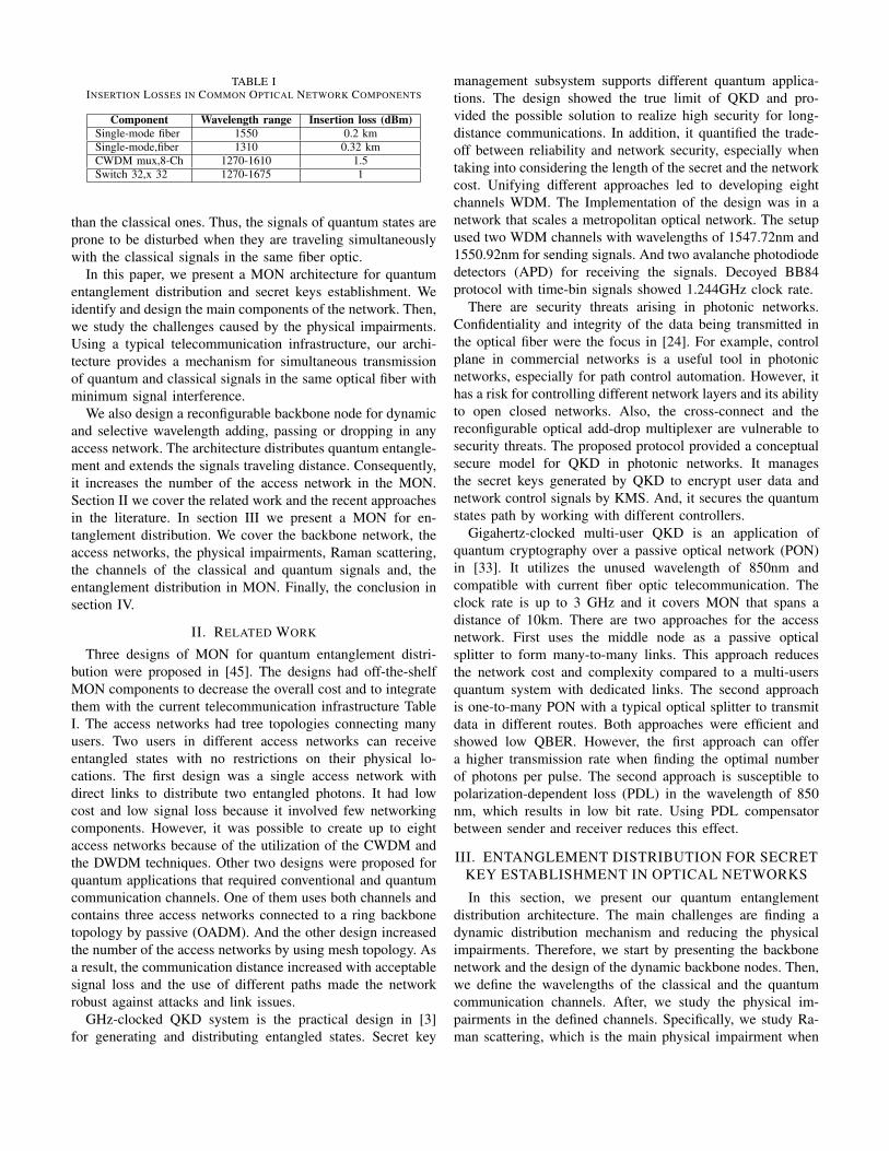
TABLE IINSERTION LOSSES IN COMMON OPTICAL NETWORK COMPONENTS
Component Wavelength range Insertion loss (dBm)Single-mode fiber 1550 0.2 kmSingle-mode,fiber 1310 0.32 kmCWDM mux,8-Ch 1270-1610 1.5Switch 32,x 32 1270-1675 1
than the classical ones. Thus, the signals of quantum states areprone to be disturbed when they are traveling simultaneouslywith the classical signals in the same fiber optic.
In this paper, we present a MON architecture for quantumentanglement distribution and secret keys establishment. Weidentify and design the main components of the network. Then,we study the challenges caused by the physical impairments.Using a typical telecommunication infrastructure, our archi-tecture provides a mechanism for simultaneous transmissionof quantum and classical signals in the same optical fiber withminimum signal interference.
We also design a reconfigurable backbone node for dynamicand selective wavelength adding, passing or dropping in anyaccess network. The architecture distributes quantum entangle-ment and extends the signals traveling distance. Consequently,it increases the number of the access network in the MON.Section II we cover the related work and the recent approachesin the literature. In section III we present a MON for en-tanglement distribution. We cover the backbone network, theaccess networks, the physical impairments, Raman scattering,the channels of the classical and quantum signals and, theentanglement distribution in MON. Finally, the conclusion insection IV.
II. RELATED WORK
Three designs of MON for quantum entanglement distri-bution were proposed in [45]. The designs had off-the-shelfMON components to decrease the overall cost and to integratethem with the current telecommunication infrastructure TableI. The access networks had tree topologies connecting manyusers. Two users in different access networks can receiveentangled states with no restrictions on their physical lo-cations. The first design was a single access network withdirect links to distribute two entangled photons. It had lowcost and low signal loss because it involved few networkingcomponents. However, it was possible to create up to eightaccess networks because of the utilization of the CWDM andthe DWDM techniques. Other two designs were proposed forquantum applications that required conventional and quantumcommunication channels. One of them uses both channels andcontains three access networks connected to a ring backbonetopology by passive (OADM). And the other design increasedthe number of the access networks by using mesh topology. Asa result, the communication distance increased with acceptablesignal loss and the use of different paths made the networkrobust against attacks and link issues.
GHz-clocked QKD system is the practical design in [3]for generating and distributing entangled states. Secret key
management subsystem supports different quantum applica-tions. The design showed the true limit of QKD and pro-vided the possible solution to realize high security for long-distance communications. In addition, it quantified the trade-off between reliability and network security, especially whentaking into considering the length of the secret and the networkcost. Unifying different approaches led to developing eightchannels WDM. The Implementation of the design was in anetwork that scales a metropolitan optical network. The setupused two WDM channels with wavelengths of 1547.72nm and1550.92nm for sending signals. And two avalanche photodiodedetectors (APD) for receiving the signals. Decoyed BB84protocol with time-bin signals showed 1.244GHz clock rate.
There are security threats arising in photonic networks.Confidentiality and integrity of the data being transmitted inthe optical fiber were the focus in [24]. For example, controlplane in commercial networks is a useful tool in photonicnetworks, especially for path control automation. However, ithas a risk for controlling different network layers and its abilityto open closed networks. Also, the cross-connect and thereconfigurable optical add-drop multiplexer are vulnerable tosecurity threats. The proposed protocol provided a conceptualsecure model for QKD in photonic networks. It managesthe secret keys generated by QKD to encrypt user data andnetwork control signals by KMS. And, it secures the quantumstates path by working with different controllers.
Gigahertz-clocked multi-user QKD is an application ofquantum cryptography over a passive optical network (PON)in [33]. It utilizes the unused wavelength of 850nm andcompatible with current fiber optic telecommunication. Theclock rate is up to 3 GHz and it covers MON that spans adistance of 10km. There are two approaches for the accessnetwork. First uses the middle node as a passive opticalsplitter to form many-to-many links. This approach reducesthe network cost and complexity compared to a multi-usersquantum system with dedicated links. The second approachis one-to-many PON with a typical optical splitter to transmitdata in different routes. Both approaches were efficient andshowed low QBER. However, the first approach can offera higher transmission rate when finding the optimal numberof photons per pulse. The second approach is susceptible topolarization-dependent loss (PDL) in the wavelength of 850nm, which results in low bit rate. Using PDL compensatorbetween sender and receiver reduces this effect.
III. ENTANGLEMENT DISTRIBUTION FOR SECRETKEY ESTABLISHMENT IN OPTICAL NETWORKS
In this section, we present our quantum entanglementdistribution architecture. The main challenges are finding adynamic distribution mechanism and reducing the physicalimpairments. Therefore, we start by presenting the backbonenetwork and the design of the dynamic backbone nodes. Then,we define the wavelengths of the classical and the quantumcommunication channels. After, we study the physical im-pairments in the defined channels. Specifically, we study Ra-man scattering, which is the main physical impairment when

the launch power of the shorter wavelength classical signalis greater than the launch power of the longer wavelengthquantum signal. We show the impact of Raman Stokes-shifton the signals of the quantum channel. After that, we showa simple design of entanglement distribution in an accessnetwork. Finally, we present the complete architecture and thenumerical results for the entire network.
A. Backbone Network
In our design, the backbone network connects many accessnetworks and has a ring topology. Reconfigurable opticaladd/drop multiplexers (ROADM) are nodes in the backbonefor selective wavelength adding, dropping, or passing. Opticalline terminals (OLT) are nodes at the end of point-to-pointlinks to multiplex a set of wavelengths into a single fiber anddemultiplex a set of wavelengths into multiple fibers. We areconsidering CWDM as the multiplexing technique in the corenetwork, which is a typical technique in the telecommunicationinfrastructures. Based on the ITU standards, CWDM grid has18 channels between 1270 nm and 1610 nm for spacingof 20 nm. We place a ROADM on the backbone for eachaccess network and OLT between the ROADM and the accessnetwork component. The OLT does not require a transponderbecause all the signals will have a wavelength that matchesCWDM or DWDM. ROADM handles traffic between thebackbone and the access network by adding, dropping, orpassing specific signals Fig. 1. We designed the ROADM usingeight channels CWDM multiplexer and 32x32 Micro-electro-mechanical systems (MEMS) optical switch Fig. 2. The inser-tion losses of the multiplexer and the optical switch are 1.5and 1 dBm respectively as in Table I. When the backbonetraffic arrives at the ROADM, it gets demultiplexed in thebackbone/ROADM to eight channels and passes to the opticalswitch inputs 1 to 8. If a signal does not belong to the currentaccess network, the switch passes it to the corresponding 1 to 8output to be multiplexed in the backbone/ROADM then passesto the backbone. Signal belonging to the access network passesto outputs 9 to 16 for multiplexing in the AN/ROADM andthen passes to the access network. Access network outboundtraffic gets demultiplexed in the AN/ROADM. Then, passesto the switch in the inputs 9 to 16. It gets multiplexed inthe backbone/ROADM then sent to the backbone. This nodeintroduces an insertion loss of 4 dBm for passing, dropping,or adding traffic.
B. Assignment of Quantum and Classical Channels
Applications of quantum cryptography requires two com-munication channels. A quantum channel to send physicalquantum states and a classical channel for information rec-onciliation and privacy amplification. So, transmitting quan-tum and classical signals in the same network is important.However, in fiber-optic communication, the launch power ofthe classical signals is much stronger than the launch powerof the quantum signals. So, nonlinear interaction occurs fromRaman scattering and four-wave mixing (FWM). For thisreason, the overlap between classical and quantum signals
OLT
Backbone
demux mux
mux/demux
mux/demux
Switch
User 1 User 2 User N
�1�2�3�4 �1�2�5�6
ROADM OLT
ROADM
OLT
User 3
AccessNetwork 2
Access Network 3
ROADM
Long-Haul
AccessNetwork 1
ROADM
OLTAccess Network 4
Fig. 1. This MON has four access networks. Incoming traffic from thebackbone arrive to the ROADM for dropping in the access network, addingdata from the access network to the backbone, or directly passing to thebackbone.
Backbonemux
mux
Backbonedemux
demux
To ANFrom AN
Dropped
signals
Added
signals
Passed signalsMEMS Optical Switch
To
Backbone
Access
Network
Fig. 2. ROADM is made of multiplexer/demultiplexer and MEMS opticalswitch. The optical switch is reconfigurable remotely to route the inputs fromthe demultiplexer to either the backbone for passing or the access networkmux for dropping. The access network demultiplexer passes signals to theswitch, which are then routed to the backbone.
become difficult to reject. Therefore, we separate the quantumand the classical signals to travel in different spectral bands.The classical signals travel in the original O-band (1260-1360). Also, the quantum signals travel within the S-band(1460-1530), C-band (1530-1565), and L-band (1565-1625).In addition, the quantum signals travel in the low loss region asthe typical attenuation loss in 1300 nm is 0.4 dBm/km while in1550 nm is 0.25 dBm/km. Based on the ITU grid standards forthe CWDM, the space between channels is 20 nm. Moreover,a pair of entangled states can travel in the S-band at 1531-1571nm and at 1511-1591 nm [46]. Consequently, entangled statescan be created in DWDM or CWDM ITU channels by fineadjustments of the light source power in the SPDC process.
C. Physical Impairments
The infrastructures of optical networks can transmit a clas-sical signal even with the existence of crosstalk. Giving that,the added noise is 40 dBm less than the launch power of theoriginal signal. The launch power of classical channels can be

Fig. 3. Shows the FWM with respect to different separation between twocontinuous wave (cw) pumps with launch power of 0 dBm. Increasing thechannel separation and the distance decreases the FWM effect.
100 dBm greater than the launch power of the quantum signals.Therefore, classical and quantum channels react differentlyto the physical impairments that occur within the channels.The source of noise in the optical networks mainly arisesfrom FWM and Raman scattering. Additionally, amplifiedspontaneous emission generated from optical amplifiers andweak isolation from the classical channels affect the quantumsignals [47]. The Interaction in fiber optic that occurs betweentwo or more pumps and the fiber optic X3 nonlinearity causesthe FWM. FWM produces most of the noise in short distancelinks when the at frequencies close to each other. However, inpractice, separated frequencies and long distance links makethe effect of the FWM much weaker than the effect of Ramanscattering. To show the impact of FWM is not within ourdefined channels, we set a two continues wave pump to 0dBm, then vary the separation between the wavelengths Fig.3. As a result, the impact of FWM decreases and becomesvery weak when the channel spacing is equal or larger than20nm. Additionally, polarization multiplexing and improvingchannel configuration reduces the impact of the FWM [48].Thus, we will examine the effects that Raman scattering hason the quantum channels.
D. Raman Scattering
In stimulated Raman scattering (SRS), the power of thelower-wavelength channels transfers to the higher-wavelengthchannels. The interactions between the photons change theirwavelength. Subsequently, this affects other channels in themedium. Increasing or decreasing a photon energy results ingenerating photons with higher and lower wavelengths thanthe original photons are referred to as Stokes and anti-Stokes,respectively. Stimulated Brillouin scattering (SBS), which isbased on the vibrational energy, has a lower effect on thequantum channel because it has a frequency shift of 10 GHz.The SBS shift is small especially for CWDM networks witha spacing grid of 20 nm. However, Raman scattering has a
Fig. 4. Shows the range of Raman gain (in arbitrary unit) caused by thepump of the classical channels. The maximum Raman gain of the 1351 nmchannel occurs at wavelength of 1435 nm. All the major noise of the classicalchannels occurred before the wavelengths of the quantum channels.
larger frequency shift up to 15 THz with intensity peak at 13THz. The direction of the frequency shift caused by the flatdispersion is free from the scattering direction. Therefore, afrequency shift occurs in the directions of the propagation aswell as the direction of counter propagation [49]. The Ramanfrequency shift is giving by:
hv′ = hv ± hfv (1)
Where hv′, hv, and hfv are the new photon energy, theincident photon energy, and the vibrational energy respectively.In our design, the classical channel at 1351 nm is closest to thequantum channel at 1531 nm. The maximum gain of Ramanscattering is known to be within 13 THz from the pump signal.So, the frequency of the classical channel is:
3 ∗ 108m/s
1.351 ∗ 10−6m= 2.22 ∗ 1014 Hz (2)
and the stokes-shift frequency is:
v′ = (22.2− 1.3) ∗ 1013 = 2.09 ∗ 1014 (3)
Therefore, the Stokes-shift will correspond to wavelength:
λ =3 ∗ 108
2.09 ∗ 1014= 1435 nm (4)
To verify the effect of Raman Stokes-shift in our architecturewe set the pumps of the classical channels to launch 0dBm at 1351,1331,1311 and 1291 nm, then we observed theRaman scattering Stoke-shift. The maximum power gain ofthe classical channels 1331 and 1351 nm occurred at 1415 and1435 nm respectively also, the peak gain power of the 1311and 1291 nm channels occurred before at 1389 and 1367 nmrespectively Fig. 4. Thus, in our design, the classical signalshave a minimum effect on the quantum channels. Also, wevaried the separation between the channels to observe thenoise reaching the quantum signals. We varied the spacing

Fig. 5. Shows the noise (in arbitrary unit) caused by the classical channelsas they get closer to the quantum channels. The lowest power gain occurs athighest channel separation.
775 nm
Light
Source
FPC
FPC
BS
ppLN1
ppLN2
PBS
demux Switch
User 1
User 2
User 3
User N
1531 1571
�1
�2
Quantum Signals Classical Signals
1291-1351
C
C
C
Fig. 6. This diagram illustrates the direct entanglement distribution in theaccess network. The output states of the process of SPDC are demultiplexedand sent to the optical network switch, then to the end users. Classicalcommunication signals between users are routed through the optical switch.
between the highest classical channel wavelength (1351 nm)and the lowest quantum channel wavelength (1511 nm). Wenotice that the noise in the quantum channels increases asthe classical channel get closer to the quantum signals Fig.5. Therefore, in our architecture, Raman Stokes-shift from theclassical channels has less impact on the quantum channels.
E. Entanglement Distribution in an Optical Access Network
Let us consider entanglement distribution and classicalcommunication in an access network. The EPR source, whichis located in the access network, have direct communicationwith all users through the optical network switch. Using laserwith pump power of -99 dBm, we setup the wavelength ofthe laser in the SPDC to create two entangled states set at1531 nm and 1571 nm Fig. 6. A WDM multiplexer carriesthe signals from the EPR source to the network switch. Then,the switch forwards the entangled states to the end users. Theinsertion losses in the CWDM multiplexer and the optical
switch are 1.5 dBm/km and 1 dBm, respectively. This resultsin a slight decrease in the coincidence rates [46]. We usedthe O-band between 1271 nm and 1351 nm for the classicalcommunication. The extra connections in the optical switchroutes the classical communication between the users [45]within the access network. Since this access network has ashort distance with few components, it has a low insertionloss close to 3 dBm.
F. Entanglement in Metropolitan Optical Network
We based the core network on ITU-T G.694.2 CWDMthat contains a grid wavelength range between 1270 nmand 1610 nm. This spectral grid has 18 channels basedon a space of 20 nm between the channels. We designatethe wavelengths between 1271 nm and 1351 nm for theclassical communication which launches signals at power of0 dBm. Also, the wavelengths 1511 nm and 1571 for thequantum communications. We setup the EPR source as acentralized node for entanglement distribution in the entireMON. Users in the same or different access networks requeststo share entanglement pairs for establishing secret keys usingentanglement-based and entanglement-assisted quantum keydistribution. When the EPR source receives a request, it createsentangled states by the process of SPDC in 1531-1571 nmor 1511-1551 nm, which correspond to CWDM channels.The output states travel from the EPR access network tothe CWDM based backbone via the local ROADM. Then,the EPR source remotely reconfigures the MEMS opticalswitches in the ROADMs to drop the wavelengths of theentangled states in the target access networks. Then, theypass through the AN/ROADM multiplexer. Then, the signalsare demultiplexed to the network switch. Finally, the opticalswitch transmits the states to the end users Fig. 7. Using thededicated and authenticated classical channel of each accessnetwork, users establishes secret keys using quantum keydistribution protocols.
In the MON, we assume that the distance between neigh-boring backbone nodes is 4 km and the distance betweenthe backbone node and the access network switch is 3.5 km.Also, we assume that the distance between the access networkswitch and the end users is 1 km. We estimate the insertionloss in the network based on loss budget of 30 dBm [36].Each access network has different insertion loss because ofthe centralized EPR source. The major insertion loss in thefirst access network results from two backbone nodes, fiberoptic attenuation, and the access network switch. Therefore,the total insertion loss in the first access network is 13.22 and10.6 dBm for the classical and quantum channels respectively.In the second access network, the signals travel through threebackbone nodes and double the distance of the first accessnetwork. The total insertion loss of the second access networkis 18.5 and 15.4 dBm for classical and quantum channelsrespectively. The insertion loss for the entire access networkin the MON is provided in Table II.
The maximum insertion loss occurs in the fourth accessnetwork as the signals travel the longest distance and pass

OLT
BackboneROADMROADM
ROADM
ROADMROADM
EPR Source
Switch
UserN
User2
User1 Access
Network 4
1291nm
1311nm1331nm
1351nm 1271nm
OLT
Switch
UserN
User2
User1
Access
Network 1
OLT
Switch
User NUser 2User 1
Access
Network 3
OLT
Switch
User NUser 2User 1
Access
Network 2
OLT
Fig. 7. This diagram shows the centralized EPR source for entanglementdistribution in MON. Quantum signals sent from the EPR travel in thebackbone network then dropped in the designated access network by theROADM. By remotely reconfiguring the optical switches in the ROADMcauses the wavelength of the entangled state to pass or drop. The wavelengthof the classical channel is fixed for each access network and used for theclassical communication between the users in different access networks.
TABLE IIINSERTION LOSS FOR EVERY ACCESS NETWORK IN MON
Network No. ROADM Loss C ch (dBm) Loss Q ch (dBm)AN-1 2 13.22 10.6AN-2 3 18.5 15.4AN-3 4 23.78 20.2AN-4 5 29.06 25
through several backbone nodes. The largest insertion lossin this network is tolerable as it falls below the acceptable30 dBm loss budget. Adding new access networks results ininsertion loss greater than 30 dBm in the new access networks.However, increasing the number of the users in each accessnetwork has no effect on the insertion loss of the accessnetworks. Consequently, the overall performance of the net-work remains unchanged. In Fig. 8 we show the optical noise
Fig. 8. Shows the optical signal-to-noise ratio in the quantum channels withrespect to different spacing to the wavelength of the classical signals.
to signal ration (ONSR) with respect to a different channelspacing between the classical and the quantum channels. Thespacing in our architecture proves better ONSR because theclassical signals have less impact on the quantum channels.Fig. 9 shows the power of the signals measured at the lastaccess network for fiber lengths of 20,40 and, 80 km.
1300 1350 1400 1450 1500 1550
Wavelength [nm]
-140
-120
-100
-80
-60
-40
-20
Signalpower[dBm]
20 km
40 km
80 km
Fig. 9. Shows the power of the signals of the classical and the quantumchannels at the last access network and under different 20, 40 and, 80 kmfiber length. Note that, the drop between 1351 nm to 1511 nm indicates thespacing between the classical and the quantum channels.
Also, we show the bit error rate in Fig. 10 with respect to thelength of the fiber optic. The fiber attenuation loss decreasesthe signal power which increases the bit error rate. It ispossible to amplify the classical signal to reduce the BER andincrease the signals traveling distance. However, there is noequivalent quantum amplifier quantum due to the no-cloningtheorem [50].
20 30 40 50 60 70 80 90 100
Fiber length [km]
0
4
8
12
16
20
BER[%]
Fig. 10. Shows the bit error rate of the classical channels for fiber lengthbetween 20 and 100 km.
We compare our network with the reference work in [45]using the same parameters in Table I. We reduced the overall

0 1 2 3 4
Access network
0
5
10
15
20
25
30
35Totalloss[dBm]
Ours Classical
Ref. Classical
Ours Quantum
Ref. Quantum
Fig. 11. Shows comparison between our network and the reference work. Wereduced the network loss and increased the number of access networks fromthree to four within the acceptable network signal loss.
network loss and increased the number of the access networksfrom three to four Fig. 11. Also, we considered a centralizedEPR source to serve the entire MON instead of local EPRsources. The design of our ROADM provides a dynamicadding, dropping, or passing of the quantum wavelengthsat each backbone node. In addition, the assigned classicalchannel provides a private communication between the accessnetworks.
IV. CONCLUSIONIn this paper, we presented a quantum entanglement dis-
tributing entangled in metropolitan optical networks. Thecentralized entanglement source serves all the users in thenetwork. It creates entangled pairs with wavelengths thatcorrespond to channels in the CWDM. By specifying thewavelengths to drop, or pass at each backbone node, weprovided a dynamic entanglement distribution for the entirenetwork. Quantum and classical signals travel in the same fiberoptic within different spectral bands. Classical signals travelwithin the range of 1271 nm and 1351 nm while quantumsignals travel within the range of 1531 nm and 1571 nm.We reduced the effect of Raman gain caused by the classicalchannels at the wavelengths of the quantum channels. Themaximum insertion loss in the network is 25 and 29 dBmfor the quantum and the classical channels respectively, whichfalls below the acceptable 30 dB budget loss.
REFERENCES
[1] C. E. Shannon, “A mathematical theory of communication,” Bell SystemTechnical Journal, vol. 5, no. 1, pp. 379–423, 1947.
[2] A. Abeyesinghe et al., “Generalized remote state preparation: Tradingcbits, qubits and ebits in quantum communication,” Physical Review A,vol. 68, no. December, p. 15, 2003.
[3] M. Sasaki et al., “Quantum photonic network: Concept, basic tools, andfuture issues,” IEEE Journal on Selected Topics in Quantum Electronics,vol. 21, no. 3, pp. 49–61, 2015.
[4] A. Waseda et al., “Quantum detection of wavelength division multiplexingoptical coherent signals,” JOSA B, vol. 27, no. 2, pp. 259–265, 2010.
[5] M. Fujiwara et al., “Exceeding the classical capacity limit in a quantumoptical channel.” Physical review letters, vol. 90, no. 16, p. 167906, 2003.
[6] M. Sasaki et al., “A demonstration of superadditivity in the classicalcapacity of a quantum channel,” Physics Letters A, vol. 236, no. 1-2, pp.1–4, 1997.
[7] M. Sasaki et al., “Quantum channels showing superadditivity in capacity,”Phys. Rev. A, vol. 58, no. 1, p. 16, 1998.
[8] M. Takeoka et al., “Implementation of generalized quantum measure-ments: Superadditive quantum coding, accessible information extraction,and classical capacity limit,” Physical Review A - Atomic, Molecular, andOptical Physics, vol. 69, no. 5 A, pp. 052 329–1, 2004.
[9] a. Waseda et al., “Numerical Evaluation of PPM for Deep-Space Links,”IEEE/OSA Journal of Optical Communications and Networking, vol. 3,no. 6, pp. 514–521, 2011.
[10] V. Giovannetti et al., “Classical capacity of the lossy bosonic channel:the exact solution.” Physical review letters, vol. 92, no. 2, p. 027902,2004.
[11] P. Hausladen et al., “Classical information capacity of a quantumchannel,” Physical Review A, vol. 54, no. 3, pp. 1869–1876, 1996.
[12] A. S. Holevo, “The capacity of the quantum channel with general signalstates,” IEEE Transactions on Information Theory, vol. 44, no. 1, pp.269–273, 1998.
[13] B. Schumacher et al., “Sending classical information via noisy quantumchannels,” Physical Review A, vol. 56, no. 1, pp. 131–138, 1997.
[14] M. Fujiwara et al., “Photon level crosstalk between parallel fibersinstalled in urban area.” Optics express, vol. 18, no. 21, pp. 22 199–22 207, 2010.
[15] C. H. Bennett et al., “Quantum cryptography,” Sci. Am., vol. 267, no.(4), pp. 50–57, 1992.
[16] J. F. Dynes et al., “Stability of high bit rate quantum key distributionon installed fiber,” Optics Express, vol. 20, no. 15, p. 16339, 2012.
[17] C. Elliott et al., “Current status of the DARPA Quantum Network,” inProc. SPIE 5815, Quantum Information and Computation III,, vol. 5815.International Society for Optics and Photonics, 2005, pp. 138–149.
[18] M. Peev et al., “The SECOQC quantum key distribution network inVienna,” New J. Phys., vol. 11, no. 7, p. 75001, 2009.
[19] K. Shimizu et al., “Performance of Long-Distance Quantum Key Dis-tribution Over 90-km Optical Links Installed in a Field Environment ofTokyo Metropolitan Area,” Lightwave Technology, Journal of, vol. 32,no. 1, pp. 141–151, 2013.
[20] D. Stucki et al., “Long-term Performance of the Swiss QuantumQuantum Key Distribution Network in a Field Environment,” New Journalof Physics, vol. 13, no. 12, pp. 1–18, 2011.
[21] K.-i. Yoshino et al., “Maintenance-free operation of WDM quantum keydistribution system through a field fiber over 30 days,” Optics Express,vol. 21, no. 25, p. 6, 2013.
[22] P. Jouguet et al., “Field Test of Classical Symmetric Encryption withContinuous Variable Quantum Key Distribution,” Optics Express, vol.10387, no. 13, p. 14030, 2012.
[23] A. Mirza et al., “Realizing long-term quantum cryptography,” Journalof the Optical Society of America B, vol. 27, no. 6, p. A185, 2010.
[24] K. I. Kitayama et al., “Security in photonic networks: Threats andsecurity enhancement,” Journal of Lightwave Technology, vol. 29, no. 21,pp. 3210–3222, 2011.
[25] M. Sasaki et al., “Field test of quantum key distribution in the TokyoQKD Network,” Optics Express, vol. 19, no. 11, p. 10387, 2011.
[26] Y. Chen et al., “Metro optical networking,” Bell Labs Technical Journal,vol. 4, no. 1, pp. 163–186, 1999.
[27] C. H. Lee et al., “Fiber to the home using a PON infrastructure,” Journalof Lightwave Technology, vol. 24, no. 12, pp. 4568–4583, 2006.
[28] S. Aleksic et al., “Quantum Key Distribution Over Optical AccessNetworks,” in Proceedings of the 2013 18th European Conference onNetwork and Optical Communications & 2013 8th Conference on OpticalCabling and Infrastructure (NOC-OC&I), 2013, pp. 11–18.
[29] J. Capmany et al., “Analysis of Passive Optical Networks for SubcarrierMultiplexed Quantum Key Distribution,” Microwave Theory and Tech-niques, IEEE Transactions on, vol. 58, no. 11, pp. 3220–3228, 2010.
[30] I. Choi et al., “Quantum key distribution on a 10Gb/s WDM-PON.”Optics express, vol. 18, no. 9, pp. 9600–9612, 2010.
[31] I. Choi et al., “Quantum information to the home,” New Journal ofPhysics, vol. 13, no. 6, p. 063039, 2011.
[32] D. Elkouss et al., “Secure optical networks based on quantum keydistribution and weakly trusted repeaters,” Optical Communications andNetworking, IEEE/OSA Journal of, vol. 5, no. 4, pp. 316–328, 2013.

[33] T. Buller, “Passive Optical Network Approach to Gigahertz-ClockedMultiuser Quantum Key Distribution,” Quantum Electronics, IEEE Jour-nal of, vol. 43, no. 2, p. 9, 2007.
[34] R. J. Hughes et al., “Quantum key distribution over a 48 km opticalfibre network,” Journal of Modern Optics, vol. 47, no. 2-3, pp. 533–547,2000.
[35] P. D. Kumavor et al., “Comparison of Four Multi-User QuantumKey Distribution Schemes Over Passive Optical Networks,” LightwaveTechnology, Journal of, vol. 23, no. 1, pp. 268–276, 2005.
[36] D. Lancho et al., Q K D in Standard Optical TelecommunicationsNetworks. Springer, 2010, pp. 1–5.
[37] W. Maeda et al., “Technologies for Quantum Key Distribution NetworksIntegrated With Optical Communication Networks,” IEEE Journal ofSelected Topics in Quantum Electronics, vol. 15, no. 6, pp. 1591–1601,2009.
[38] J. Martinez-Mateo et al., “Quantum Key Distribution Based on SelectivePost-Processing in Passive Optical Networks,” IEEE Photonics Technol-ogy Letters, vol. 26, no. 9, pp. 881–884, 2014.
[39] M. Razavi, “Multiple-Access Quantum Key Distribution Networks,”IEEE Trans. Commun., vol. 60, no. 10, pp. 3071–3079, 2012.
[40] P. D. Townsend, “Quantum cryptography on multiuser optical fibrenetworks,” Nature, vol. 385, no. 6611, pp. 47–49, 1997.
[41] P. Townsend, “Experimental investigation of the performance limits forfirst telecommunications-window quantum cryptography systems,” IEEEPhotonics Technology Letters, vol. 10, no. 7, pp. 1048–1050, 1998.
[42] P. Townsend et al., “Design of quantum cryptography systems forpassive optical networks,” Electronics Letters, vol. 30, no. 22, p. 1875,1994.
[43] G. P. Ryan, “Dense wavelength division multiplexing networks,” IEEEJournal on Selected Areas in Communications, vol. 8, no. 6, p. 23, 1997.
[44] A. Ciurana et al., “Quantum Metropolitan Optical Network based onWavelength Division Multiplexing,” Optics express, vol. 22, no. 2, p. 23,2013.
[45] A. Ciurana et al., “Entanglement distribution in optical networks,”Selected Topics in Quantum Electronics, IEEE Journal of, vol. 21, no. 3,pp. 37–48, may 2015.
[46] I. Herbauts et al., “Demonstration of active routing of entanglement in amulti-user network,” Optics Express, vol. 21, no. 23, pp. 29 013–29 024,2013.
[47] N. A. Peters et al., “Dense wavelength multiplexing of 1550 nm QKDwith strong classical channels in reconfigurable networking environ-ments,” New Journal of Physics, vol. 11, no. 4, p. 45012, 2009.
[48] B. Qi et al., “Feasibility of quantum key distribution through a densewavelength division multiplexing network,” New Journal of Physics,vol. 12, no. 10, p. 103042, 2010.
[49] P. Eraerds et al., “Quantum key distribution and 1 Gbit/s data encryptionover a single fibre,” New Journal of Physics, vol. 12, no. 6, p. 9, 2009.
[50] W. K. Wootters et al., “A single quantum cannot be cloned,” Nature,vol. 299, no. 5886, pp. 802–803, oct 1982.