quantum cryptography networks supporting path verification
TRANSCRIPT

1
Quantum Cryptography Networks SupportingPath Verification in Service Function Chains
A. Aguado, D. R. Lopez, A. Pastor, V. Lopez, J. P. Brito, M. Peev, A. Poppe, and V. Martın,
Abstract—Quantum Key Distribution is a physical tech-nology that enables the secure generation of bit streams(secret keys) in two separated locations. This technology isdesigned to provide a solution for very secure (quantum-safe) key agreement, which is nowadays at a risk due toadvances in quantum computing. The recent demonstrationof a QKD network in the metropolitan area of Madridshows how these networks can be deploy in currentproduction infrastructure by following existing networkingparadigms, such as Software-Defined Networking (SDN). Inparticular, a three-node QKD network is implemented onthe metropolitan area network using existing infrastructureand coexisting with other data and control services.
On the other hand, telecommunication networks aredrastically changing the way the services are architectured.Users of the operator’s infrastructure are moving from tra-ditional connectivity services (e.g. virtual private networks-VPNs-) to a set of interconnected network functions, eitherphysical (PNF) or virtual (VNF), in the shape of servicefunctions chaining (SFC). However, SFC users do not havea method to validate that the traffic flow is appropriatelyforwarded across the nodes in the network, situation thatmay lead to very critical security breaches (for example, asecurity node or a firewall that is bypassed on the chain).This work presents a method for validating ordered proof-of-transit (OPoT) on top of the Madrid Quantum Network.We first provide an general description of the QKD networkdeployed in Madrid. Then, we describe an existing securityprotocol for proof-of-transit in packet networks, analysingits issues and vulnerabilities. Finally, this work presents aprotocol for alleviating the security breach found in thiswork and for providing ordered proof-of-transit (OPoT) inSFCs. Finally, an example of the real implementation isshown, where nodes being part of the OPoT scheme areprovisioned with QKD-derived keys.
Index Terms—Proof of Transit, Quantum key distribu-tion, Network virtualization, Software Defined Networks.
I. INTRODUCTION
A. Aguado, J. P. Brito and V. Martin are with Center for Com-putational Simulation, Universidad Politecnica de Madrid, CampusMontegancedo, 28660 Boadilla del Monte, Madrid, Spain (e-mail:{a.aguadom, jp.brito, vicente}@fi.upm.es).
D. R. Lopez, A. Pastor and V. Lopez are withTelefonica GCTO, Ronda de la Comunicacion s/n 28050Madrid, Spain (e-mail: {diego.r.lopez, antonio.pastorperales,victor.lopezalvarez}@telefonica.com).
M. Peev and A. Poppe are with Huawei Technologies Dues-seldorf GmbH, Riesstrasse 25, 80992 Munchen, Germany (e-mail:{momtchil.peev, andreas.poppe}@huawei.com).
Manuscript received August 14, 2018.
THE conventional data and control communicationchannels within the telecommunication networks
are under risk due to the advances on computation.Traditional cryptosystems, that tipically use public en-cryption algorithms (in particular for secret key agree-ment), are at risk due to developments in computing.More specifically, the evolution of quantum computingcan compromise the existing cryptosystems, which basetheir security in mathematical problems that, while areassumed complex to solve in classical computing, areeasy in quantum computers. QKD is immune to thisthreat [1], [2]. It allows to generate synchronized randombits in two sources that are separated in space, with theadditional property that the maximum information leakedout during the QKD process can be upper bounded.This means that the random bits can be used as asecret key. The security of the QKD keys is due to thelaws of quantum mechanics and, therefore, independentof any computational assumption and immune to anyalgorithmic cryptanalysis.
QKD is a new opportunity for operators as it bringsan additional physical layer for securing the communi-cations infrastructure. The Madrid Quantum Network,presented in [3], [4], is a new QKD network that dis-tinguishes itself in using operational infrastructure andcarrier-grade optical devices to transport the quantumchannels together with multiple classical channels in ashared quantum-classical infrastructure that is managedand exploited through the SDN and NFV paradigms.The network has been recently deployed in downtownMadrid, across a metro area network. This networkacted as the main source for symmetric keys that wereused to secure control [5] and data [6], [7] channels,demonstrating how QKD is a suitable technology forsecuring the infrastructure and services by combiningexisting key exchange algorithms together with quantum-generated keys in a hybrid quantum and classical securityscheme.
Aside from the traditional control and data channelsdescribe above, the network architecture and the ser-vices deployed on top are drastically changing, forc-ing operators to evolve from traditional/legacy, non-scalable networks towards new architectural solutions.This evolution is powered mainly by three differentsources, first the development of new hardware devices

2
and the increased capacity of existing ones. Second,the creation and re-definition of existing control planeand routing protocols (e.g. segment-routing [8], key-flow) and third, the evolution towards software-definedand virtualized networking architectures. This progress(specially SDN [9] and NFV [10]) allows to dynami-cally allocate network resources per-user/service and on-demand. However, the flexibility brought by the newsoftware networking trends also carry certain associatedvulnerabilities and implications. For instance, in a virtu-alized environment, several functions might be deployedin distributed locations for composing a service functionchain (SFC) [11]. Both control and data communicationsmust be appropriately secured, as any attempt to compro-mise a virtual function or its behaviour can compromisethe entire infrastructure.
A wide-spread concern about virtualized network ele-ments is related to traffic attestation. Any network devicedeployed in a production network must be capable ofassessing if a specific traffic flow passes through it andis correctly forwarded. If a node cannot guarantee thiscapability, it will not be accepted for production de-ployment. By progressively changing physical networkfunctions (PNFs) by virtual network functions (VNFs),this task becomes harder. As the traffic traverses multipleintermediate nodes (possibly, out of the control of theVNF operator), it could eventually bypass a critical nodewithin the SFC (e.g. a firewall). In order to mitigate thisissue, a first-of-a-kind proof-of-transit technique [12] hasbeen developed within the IETF to verify if a packethas traversed all the nodes within a path. By unique orfirst-of-a-kind we mean that there is no similar approachdefined or available in previous studies. The closestsolution is also described in the very same document,which implies a nested encryption scheme. This is com-putationally costly for network elements and requiresmore data to be transmitted per packet (higher overhead).Other solutions have studied similar approaches usingmathematical theorems for networking purposes. Anexample is described in [13], where authors implementeda routing protocol based on residual number systems(Chinese remainder theorem). Although very innovative,this method does not focus on traffic attestation, as itdefines a low-consumption routing method based onmodular operations. The PoT approach originally definedin [12], as we further describe in the next section, doesnot verify order of the followed path, whilst also havesome vulnerabilities associated. These weaknesses couldpotentially be exploited by a given attacker to bypassnodes in the chain, opening security breaches (e.g. thebypass of a firewall or security gateway). Symmetric keyencryption can be used as a way to enhance the existingsolution by securing and adding further capabilites, as itis discussed below.
In this work, we propose a way to enhance the currentPoT scheme proposed in [12], by using symmetric keyencryption (potentially, one time pad -OTP- [14], butcould be any other algorithm) for ciphering or maskingthe associated traffic’s metadata. Firstly, we provide anoverview of the Madrid Quantum Network (MQN), a realQKD network deployed in Telefonica Spain’s productionfacilities where the experiments were done. Then wedescribe the existing technique for implementing PoT,while we analyse the vulnerabilities of the scheme. Ourproposal not just solves these vulnerabilies within thecurrent model, but goes beyond by providing order tothe proof-of-transit scheme (OPoT) in an clean andeasy to implement way. These enhancements have beenpresented by the authors of this paper in the IETF and arecurrently being proposed as the way to implement orderin the solution presented at the IETF draft, replacing theprevious nested encryption proposal. Also, in order toprovide a practical demonstration of the highest possiblesecurity (secure symmetric keys) and going beyond atypical setting, we have implemented the solution overthe MQN. This allows to show how the solution can alsointegrate well with less standard techniques. Using QKDalso allows to demonstrate a quantum-safe technique thatwill survive in case of major algorithmic threats (e.g. theone posed by quantum computers).
II. THE Madrid Quantum Network -MQN- FIELDTRIAL
The Madrid Quantum Network (MQN) [3], [4] hasbeen recently deployed in a metropolitan area networkaround Madrid city center. The network has three mainlocations: Almagro (Telefonicas I+D laboratory sharedwith Telefonica Spain PoP), Norte and Concepcion (bothare Telefonica Spain PoPs). The three nodes and thethree connections (three pairs of fibers) are part ofTelefonica Spain production network. The QKD systemswere developed by Huawei Research Center Germanyusing continuous variables technology [15], [16], [17]that is more resilient to noise from the classical channelssharing the same fibre with the quantum channel. TheQKD network manage the key generation according toSDN principles by switching the quantum states gener-ated by the single transmitter to one of the both receivers.This control by an SDN network was one of the designtargets of the Madrid Quantum Network testbed and arequirement for quantum/classical network convergence.Almagro hosts the QKD transmitter, while two QKDreceivers are distributed to Norte and Concepcion. Theconnection go across other PoPs, where splices andconnectors in patch panels causes additional fiber losses.Some general parameters of the links:
• Almagro-Norte: around 3.9km long with a loss of6dB and a key generation capability -estimated from

3
the raw key- above 70kbps, with coexistence of 17classical channels together with the quantum one inthe same (C) band. This limit was due to the numberof free slots available in the optical equipment, sothe number could be higher.
• Almagro-Concepcion: around 6.4km long with aloss of ∼ 7dB. We artificially increased the dis-tance/losses by adding a 20km fiber spool with 4dBof loss. This was done also to increase the Ramannoise from the classical co-propagating channels(i.e. a worst case situation for the transmission ofquantum signals). In this combined configurationthe key generation capability was above 20kbps,with coexistence of quantum and classical channels.
• Norte-Concepcion: ∼ 7dB losses, carrying onlytelecom channels (using the QKD network with amulti-hop/virtual link).
Fig. 1. The QKD testbed in Madrid: Map view.
In Fig. 1, we show a map of the network, alsoindicating the links with an approximation of the fiberspath. The actual deployment might not follow this short-est path but a more complex and longer path due toexternal restrictions. Although there is no direct quantumlink between Norte and Concepcion, the QKD keysprovided by a SDN-based QKD network management(key management layer) over the trusted node Almagroin a multihop scheme are used here i.e. we have herea virtual QKD connection, as opposed to the direct,physical, connections through a direct and uninterruptedquantum channel.
The quantum channel is multiplexed together withother classical (data and management). The maximumnumber of co-propagated channels was 17, but thisrestriction came not from the QKD devices, but from thelimited availability of the number of client ports in theoptical networking equipment (standard Huawei’s OptixOSN 1800 systems) used to multiplex/demultiplex thechannels in the fibre.
III. EXISTING PROOF-OF-TRANSIT TECHNIQUE
The latest version of the PoT technique can be foundin [12], which is an IETF working group document(WGD). In the next subsection we explain the generalconcept, before going into the details of the existingweaknesses of the scheme. The idea is to create a mastersecret which can be disclosed only if all participants inthe scheme provide its share of the secret. In this sense,the verification node will prove if all nodes involved ina path (as show in Fig. 2) have provided its share toreconstruct the secret. The mathematical concept behindis the Shamir Secret Sharing (SSS) technique [18], whichis based in the fact that a polynomial of degree n − 1(the secret) is uniquely determined when n interpolantpoints of the polynomial (the shares) are known.
A. Description
The steps described in the IETF’s PoT WGD are asfollows:
• The first step is to create the scheme. An entity(which could be a SDN controller) must createit. This includes choosing a big prime number,generating the two polynomials -P1(x) and P2(x)-(for the given number of nodes in the path), se-lecting the points for each node and generatingthe (as defined in the WGD) Lagrange PolynomialConstants (LPCs) per point. Lagrange polynomialformalism is used throughout since once calculatedthe basis, that is fixed for a set of abscissae,the evaluation of the corresponding interpolationpolynomial is fast. The first polynomial is the secretin the SSS scheme, while the second polynomial isused for randomising the scheme, so that it can bereutilised and not just for a single packet (for moreinformation refer to [12]).
• After this calculation, the entity (controller) sendsthe computed PoT metadata (see Fig. 5 and relatedexplanations for details) to each node in the path.This metadata will be stored by the node and usedwhen required over the PoT flow.
• For any incoming packet, the source node in thepath generates a random number between 0 andthe prime p. This random value (RND) is used asthe constant coefficient of the second polynomial.This procedure is done to randomise the scheme perpacket, avoiding to regenerate the scheme for eachnew packet of the flow.
• Any node i (including the source and destinationof the path) for a given packet j will perform thesame operation in order to update the cumulativeverification value (CML). At the first node, CML0
is consider zero, as it is the first node generating the

4
cumulative value.
CMLji = (P1(xi) + (P2(xi) +RNDj)) ∗ LPCi
+ CMLi−1 (mod p)
• The packets are sent between the nodes in the chain,using the encapsulation defined by the in-situ OAMdatagrams [19]
• After updating the cumulative value with its ownshare, the destination/verificator node compares thecumulative value generated with the sum of themaster secret plus the random number RND:
CMLn == Secret+RND (mod p)
• If the verification succeeds, the verification noderemoves the PoT header (metadata) from the packetand forwards it to the next node (outside the path).
• If the verification fails, an action will be taken withthe packet based on predefined policies (e.g. dropthe packet).
Fig. 2. Example of network and PoT path.
This technique allows to verify that a traffic has gonethrough a set of nodes within a path, but not the orderwithin the path. For this reason, the PoT WGD alsoproposes using cumulative encryption technique, whichwill require the verification node to synchronize sym-metric keys with every node in the path. Furthermore,the associated overhead per packet will be at least of thenumber of bits of the symmetric secret key (e.g. 256 bitsif AES-256 is used), with the associated computationalcomplexity (and hardware requirements) needed for thenested encryption and secret key creation (e.g. Diffie-Hellmann, which is computationally costly).
Section 8 of the draft claims that the security fromthe original SSS scheme (information theoretic secure- ITS) can be inherited and that, in consequence, it isimpossible to break as long as some conditions are met:the polynomial must of degree k for chains of k+1 nodesand that the values used for the reconstruction are keptsecret by the nodes. Also, the draft mentions the numberof packets that can be validated by the scheme is similiarto the prime number chosen. In the next subsection weshow that some of the assumptions are not valid, as agiven attacker could potentially break the scheme andbypass a set of nodes by reading the OPoT packets
metadata [19] (in a mixture of what the draft calls inter-node and inter-packets cryptanalisis). We evaluate thecurrent weaknesses of the SSS-based scheme (not thenested encryption), to provide a better context for oursolution.
B. Vulnerabilities
Initially we will assume that two packets(packet1, packet2) can be captured just after thefirst node in the path. Let P1(xi) be the result of thefirst polynomial for xi (point assigned to nodei), andP2(xi) be the result of the second polynomial withoutthe constant part. Then let RNDj be the constantpart of the second polynomial for a given packetj andCMLj
i be the cumulative value for a packetj after thenodei. LPCi stands for Lagrange Polynomial Constant,meaning the Lagrange basis polynomial constant for thepoint xi. Both xi and LPCi must be kept secret. Then,by capturing two packets we get:
CML11 = (P1(x1) + P2(x1) +RND1)
∗ LPC1 (mod p)
CML21 = (P1(x1) + P2(x1) +RND2)
∗ LPC1 (mod p)
from where
CML11 − CML2
1 (mod p)
= (RND1 −RND2) ∗ LPC1 (mod p)
and
LPC1 =CML1
1 − CML21
RND1 −RND2(mod p)
For a given node i the result will be:
CML1i = (P1(xi) + P2(xi) +RND1)
∗ LPCi + CML1i−1 (mod p)
CML2i = (P1(xi) + P2(xi) +RND2)
∗ LPCi + CML2i−1 (mod p)
from where((CML1
i − CML1i−1)−
(CML2i − CML2
i−1))(mod p)
= (RND1 −RND2) ∗ LPCi (mod p)
LPC1,2i =
(CML1i − CML1
i−1)− (CML2i − CML2
i−1)
RND1 −RND2(mod p)

5
Where we use LPC1,2i to mean the LPCi generated
by the captured packets 1 and 2. The LPCi value mustbe unique, but we still don’t know the prime p used forthe module operation, making its calculation hard. If l,2 < l < 10! is the number of LPCy,z
i ∈ Z, then wecould calculate (l − 1)! combinations of:
LPCy,zi = LPCi +my,z ∗ p,my,z ∈ Z
LPCv,wi = LPCi +mv,w ∗ p,mv,w ∈ Z
LPCy,zi − LPCv,w
i = (my,z −mv,w) ∗ p
And then we can calculate (using the division resultsthat belong to the set of integers) the set:{(m1,2−m1,3) ∗ p, ..., (m1,4−m3,7) ∗ p, ...}, (mk,l −
mr,s) ∈ ZFrom where we could try to derive the prime (e.g.
m.c.d, decomposing several p and operating them toverify if they fit). If the prime p is obtained, the PoTschema is compromised and the rest of the demonstrationis as follows.CMLj
i and RNDi are public (openly encapsulatedin the packet metadata). Therefore, assuming the trafficcould be tampered at any point (and p has been ob-tained), we could calculate for a given setup of the PoT,the set {LPC1, ..., LPCn−1} by tracing two differentpackets (and their PoT metadata).
Let’s now assume that a third packet (packet3) tra-verses the network. We will check if, by knowingRND3, we could calculate CML3
j values. Although thiscannot be done in principle, since the calculation of therandom constant is done internally in the first node, wecan start calculating CML3
1:
CML11 = (P1(x1) + P2(x1) +RND1) ∗ LPC1
⇒ (P1(x1) + P2(x1)) ∗ LPC1
= CML11 − (RND1 ∗ LPC1)
CML31 = (P1(x1) + P2(x1) +RND3) ∗ LPC1
= (P1(x1) + P2(x1)) ∗ LPC1 +RND3 ∗ LPC1
= CML11 − (RND1 ∗ LPC1) +RND3 ∗ LPC1
= CML11 + (RND3 −RND1) ∗ LPC1
For a given node i the result will be:
(P1(xi) + P2(xi)) ∗ LPCi =
CML1i − CML1
i−1 − (RND1 ∗ LPCi)
CML3i =
= (P1(xi) + P2(xi) +RND3) ∗ LPCi + CML3i−1
= (P1(xi) + P2(xi)) ∗ LPCi +RND3 ∗ LPCi+
+CML3i−1
= CML1i − CML1
i−1 − (RND1 ∗ LPCi)+
+RND3 ∗ LPCi + CML3i−1
leading to:
CML3i = CML1
i − CML1i−1+ (1)
+(RND3 −RND1) ∗ LPCi + CML3i−1
Then, by tracing the traffic before and after a singlenetwork node i, we could bypass that node of thePoT path by getting the packet, and calculating thecorresponding CMLnew−packet
i . If the information isgathered at each hop of the path, we could also growthe secret up to the n − 1 hop by getting the packet atthe first node, bypassing the whole path. For example,using directly formula 1 on the second node produces:
CML32 = CML1
2 − CML11+
+(RND3 −RND1) ∗ LPC2 + CML31
since all the values are know, CML32 can be generated
and then node 3 can be bypassed. This could be thengrown for any node i. Note that these operations mustbe also done (mod p). This assumes that the prime pcan be disclosed as initially shown.
To verify that such an attack is feasible under normalconditions, where a low overhead is required, we gener-ated different 32 bits prime numbers and their randomilygenerated PoT schemas, including the two polynomials,the points and the LPCi for each node in the path.The simulation was implemented to capture the first100.000 packets (out of a maximum of 232 packets),failing if it did not find a valid solution (i.e. the primenumber and the attack for a given packet). In most ofthem (above 85%) we could succesfully obtain the primenumber and replicating the schema (gathering packetsat any intermediate hop in the path). Further tests withsmaller prime numbers were executed, as it is shown inthe results section.
Incrementing the size of the prime number wouldincrease the complexity of disclosing enough data tobreak the solution, but it will also increase the cost ofgrowing the secret and, more importantly, will requireto expand the PoT header for each packet, increasingsubstantially the overhead.
Also, [12] proposes an alternative solution to includeorder as a capability of the solution. This technique isbased on nested encryption to generate a secret using a

6
symmetric ciphering method (e.g. AES). As it is defined,it is not just a complement to the existing proposal butmore a new solution itself, as it does not need a SSSscheme to work in parallel. However, this also has someassociated drawbacks: it is computationally more costly,it requires an additional overhead (at least the size ofthe key 256 of control information per packet) and itrequires the node in charge of verification to securelygenerate symmetric keys with all the nodes in the path.For this last point, if keys are to be refreshed in a perpacket basis, it will require the validation node to keepa continuous flow of secret keys with every node.
For this reason, we explored the possibility of inte-grating symmetric encryption algorithms not replacing,but working together with SSS scheme. This not justmitigates the security issues that the current solutioncontains, but can also be used to provide order to thePoT verification scheme.
IV. PROPOSED ENHANCEMENT
The purpose of this section is to provide a detaileddescription of the proposed solution extended to in-clude order. Our technique enhances the solution in[12] while being compatible with it. It utilises stan-dard techniques from traditional symmetric encryptionalgorithms and provides the flexibility to define mul-tiple options/embodiments for providing different levelof assurance (LoA). The next subsection provides adescription and an example of our solution.
Fig. 3. High level view of the internal node steps for providing OPoT.
A. Description
To enhance the security of the existing solution, theproposed technique combines the SSS scheme withsymmetric key encryption in a per-hop basis, securingthe SSS metadata on each hop. This addition also allowsto reduce the polynomials to only one, by keeping therandom number generation at the source node of thepath. Let us remark that our proposal is compatible withthe existing one, as both polynomials can be kept (andalso be exposed as a LoA capability). Note that the maindifference of maintaining the two polynomials against
using just one is to keep a constant coefficient (the secret)different from zero, so either possibility (two or onepolynomials) is compatible with our proposal.
Fig. 3 shows a high level view of the internal logicalcomponents of a network device performing the OPoT.These components are divided in four steps (packet iden-tification, decryption, SSS core, encryption). A detailedview of the steps for any intermediate node (i) in thepath is as follows:
A The first step consists on the identificationof the packet and verifies if it matches arouting/forwarding entry (in Fig. 3, from theflow table) that is associated with the OPoTmechanism. If so, it gathers the appropriatesymmetric keys (previously exchanged/agreedwith the previous nodes i− 1 and i+1 withinthe path) from the key store and provides it tostep B and step D for the decryption/encryptionof the SSS metadata (CML and RND).
B The second step involves the disclosure ofthe ciphered SSS metadata within the packetsheader. When this process is finished and themetadata is updated (with the valid open val-ues) it is handled to step C.
C During this step the node updates the SSSmetadata by performing the very same recon-struction as described in the previous sectionusing its own shares of the secret. This, aspreviously mentioned, can be done either forone:
CMLi = (f(xi) +RNDj) ∗ LPCi+
+CMLi−1 (mod p)
or two polynomials:
CMLi = (P1(xi) + (P2(xi) +RNDj))∗∗LPCi + CMLi−1 (mod p)
D The final step will require to cipher the dataupdated by the process in step C, using theappropriate symmetric keys (previously ex-changed/agreed with the previous node i + 1within the path). After ciphering the SSS meta-data, the node forwards the traffic to the net-work, using the information from the forward-ing/routing table (as done in any traditionalnetwork).
It is important to note that the source and destinationnode slightly differ on some of the steps described above;
• Source node: In Step A there is no need for iden-tifying a symmetric key, as traffic comes with noSSS header. In consequence, step B is not required.Step C will also require the source node to generate

7
a random number (between zero and the primenumber) per packet. Step D works as defined before.
• Destination node: Step A and B works similarlyas in the general description, but there is no needfor gathering a next-node symmetric key (as it isthe destination node). In consequence, step D isnot required. Step C, apart from behaving as in thegeneral description, it verifies the generated data (ifthe OPoT works) and removes the SSS metadatafrom the packet’s header.
Fig. 4. High level view of the internal node components for providingOPoT.
Fig. 4 shows in a higher level view how the meta-data from the SSS is treated before and after passingthrough the OPoT-enabled node. The proposed techniqueis compatible with novel network paradigms: a SDNcontroller could be the master entity in charge of creatingthe SSS data (prime, polynomials, points, LPCs) anddeploying the OPoT path, while the solution is easilyintegrable and suits particularly well in virtualized en-vironments (NFV). In addition, different key exchangetechniques can be applied for providing keys at eachpoints, depending on the available resources and the LoAassociated with the traffic flow. For example, traditionalkey exchange algorithms (e.g. Diffie-Hellman), post-quantum algorithms or QKD could be used as the sourceof symmetric keys. Which one to use would depend onthe available infrastructure (e.g. QKD modules, HSMencryptors), the LoA agreed for the service or theoverhead acceptable for the traffic flow.
Fig. 5. Example of the scheme using a single polynomial combinedwith the per-hop encryption.
In Fig. 5 we show in detail a simple execution us-ing four nodes (n1, n2, n3, n4) performing the proposedscheme. If a packet leaving the ingress node (n1) goesto the third node (n3), bypassing one intermediate node
(n2), the values used for the calculation will be acombination of cml and rnd, both XORed with the twointermediate (and different) keys used between the firstand second nodes (n1, n2) and the second and third nodes(n2, n3). The data used in the example are:
Prime number: p = 71Polynomial: 61x3 + 55x2 + 10x with no constant
coefficient.The nodes are given the values {xi, yi, lcci, p}• n1 : {39, 67, 45, 71}• n2 : {96, 69, 10, 71}• n3 : {36, 53, 30, 71}• n4 : {68, 25, 58, 71}with no verification value, as the transmitted rndj will
be used for verification, for a given packet j. In thefigure, ecml and ernd stand respectively for encryptedcml and rnd values. The nodes show the internal stepsinvolved in the OPoT for this specific path. The ingressnode (n1) generates the random value rnd to be used asthe constant coefficient of the polynomial (also namedrps, random polynomial secret), which is the secret. Thisrandom value, (rnd = 12 in the example), is transmittedwith the packet and ciphered per hop. Each node in thepath decrypts the OPoT metadata, reconstructs its partof the secret using its part of the share and the OPoTpackets metadata, ciphers the new values and transmitsthem to the subsequent node in the path. The top partof Fig. 5 shows the encryption of the OPoT metadata,while the bottom part shows each nodes share and thegenerated cml. The verification node (n4) finally checksif cml == rnd (in this case, succeeding 12 == 12),allowing the packet to be forwarded if the verificationsucceeds.
B. Key Improvements/Capabilities
Our proposed solution, while being compatible withthe exiting proposal, brings some additional enhance-ments. Both the enhancements and the maintained capa-bilities are:
• The fundamental enhancement comes from the up-grade on the security of the existing scheme. TheSSS metadata is ciphered per hop, avoiding thatany evesdropper gathers and analyses the data toperform an attack similar to the one describedabove.
• A second (but no less important) enhancementis that our solution brings order to the solution.If the packet is not correctly forwarded betweenthe nodes (e.g. it goes from the first to the thirdnode), the node receiving the packet won’t havethe corresponding key, so it will wrongly decryptthe metadata, leading to a wrong construction ofthe secret.

8
• It is compatible with the existing solution, so thescheme can be randomised per packet.
• The first solution for reducing an attack is in-creasing the size of the prime number, thereforeincreasing the overhead. Our solution allows not toincrease the size of the prime number and, in thissense, reduce the overhead of the solution.
• As mentioned above, our solution allows to simplyuse a single polynomial, while being compatiblewith the two polynomial approach of the existingsolution.
• In the IETF WGD [12], the proposal for orderedPoT requires nested encryption. This solution needssome computational capabilities. It also needs thatthe final node has active key exchange systemswith all the other nodes in the path and brings anoverhead of at least the size of the key bits perpacket. Our solution does not have such compu-tational complexity (a simple XOR operation canbe used) and the packet overhead is also reduced,as there is no need to increase the key size forincreasing the security of the scheme.
• This solution can be complemented with differentLoA profiles, based on multiple variables:
– Size of the scheme (the size of the primenumber): Increasing this value may affect thethroughput, while keeping it small could besuitable for low rate services. Smaller schemescan be usable for more traffic, due to theimprovements of our proposal.
– Source of the symmetric keys: keys can begenerated from different sources,
C. Future Possibilities
We note, without going into details, that there areapproaches based on frequent key exchange, whichare completely unrelated to the method presented in[12]. These are based on Message Authentication Code(MAC) algorithms [20] that ensure the integrity andthe source of information of received messages. Thesaid algorithms are known to be secure if an adequatefrequency of exchange of secure key material is guaran-teed. An extreme example of this class are MACs thatensure Information Theoretically Secure (ITS) messageauthentication [21] - ones that cannot be broken by anycryptoanalytic method, provided that the key is changedat every MAC application, they are absolutely secure,i.e. they preserve the secrecy of the message and areunforgeable by the adversary. The quality of the keymaterial generated by QKD is a very good approximationto this requirement. It should be taken into account thatpresent and foreseeable QKD key generation rates areinsufficient for ITS MACs, if these would be applied to
every single packet. However, packets can be aggregatedin larger frames and ITS MACs can be applied to these,provided the nodes possess a source of ITS key genera-tion. Naturally such a strategy comes at the expense ofa loss of all packets in a frame (and the need of theirresending) when a MAC fails. Alternatively, however,the application of non-ITS MACs can be used takinginto account a careful calibration of the key exchangerate in order to meet a given security policy.
V. EXPERIMENTAL RESULTS
A. Brute force attack on the existing solution
The brute force attack results are summarized inFigs. 6 and 7. In both graphs the x-axis shows the primenumber used for the demonstration.
The first graph (Fig. 6) shows the average numberof packets captured at each hop and used to break thescheme, calculating the LPCs and the prime number.The second graph (Fig. 7) shows similar informationbut as the percentage of packets that are required tobe listened to break the scheme for different primenumbers. The percentage is calculated by dividing theaverage number of packets by the total amount of packetsassumed to be secured by the scheme (which is the primenumber used to generate the scheme).
These tests were executed 10 times for each scheme,having 10 schemes for prime number amounting to atotal of 100 tests for each prime number. For example,for the prime 1003161329, we run 100 tests with anavarage of 34890 packets captured to break the scheme(a minimum of 10058 and maximum of 71964 wereobserved). The graphs also indicate that, even when therequired number of packets increases as we use biggerprimes, the growth in the average value for each primedoes not increase drastically (as fast as the prime numberis increased) and, in this sense, the calculated percentage(average number of packet to break the system vs theprime number).
Fig. 6. Average of number of packets required to break a 5 nodesschema for a given prime number (x-axis).

9
Fig. 7. Percentage of packets required to break a 5 nodes schema for agiven prime number (average divided by the prime, which is assumedto be the maximum number of packets to be secured by the PoT).
B. Demonstration over the Madrid QKD network
The experimental setup is composed by three PoPdistributed in Madrid’s production network, as describedin the previous section. At each location, our physicaltestbed comprises:
• a QKD system (either a transmitter or receiver),• a server that contains the SDN software for man-
aging the QKD systems and the key stores, thesoftware for the QKD system operation and the pro-cesses implementing the OPoT solution (the nodesthat form the path and the controller), allocated inseparate virtual machines.
• a Huawei’s Optix OSN 1800 optical transmissionsystem aggregating data, control and quantum chan-nels. These are completely off-the-shelf devices.
Our two network layers (the data and QKD) are shownin Fig. 8. The lower layer shows the QKD domain. Itis composed by the three physical QKD systems, itsmanagement software (internal, key stores and a SDN-agent) and a SDN controller, physically located withinAlmagro’s PoP. The SDN agents at each location cancommunicate with the centralized controller via well-defined information models and interfaces (RESTconf).Through them, the controller is capable of deployingand switching the physical QKD channels (Almagro-Norte and Almagro-Concepcion), creating a virtual QKDlink using Almagro’s PoP as a secure key relay node,and detecting, tracking and handling the incoming key-consuming applications (in our case, the four nodesperforming the OPoT).
The upper layer (data) is composed by four nodes.The path connecting the nodes starts in a process locatedin Norte’s PoP. It transmits the data to the secondnode/process, located in Almagro. From Almagro thepath goes to the process at Concepcion, which finallycloses the loop by sending back the data to a secondprocess located in Norte. In this way, we make sure
Fig. 8. Setup of the two logical layers within Madrid’s Quantumnetwork: the QKD layer (lower part) and the data, OPoT layer (upperpart).
that the applications consume keys from every (eitherphysical or virtual) QKD link. The implemented ap-plication, selected only as a simple showcase, was thetransmission of raw messages simulating a chat within asecure locations (the PoPs). Other, more significant usecases, for example, the verification of a QKD key relay(or virtual link) over a QKD network have been alsoimplemented.
The workflow for this demonstration is as follows:
• Initially, our source node needs to communicatewith the controller for requesting the deploymentof an OPoT flow/path. This request (as other mes-sages in the workflow) has been implemented overUDP datagrams. A more network-oriented approachwould be to implement the channel following SDNstandards (e.g. OpenFlow/NETCONF), while fora quantum-safe communication between node andcontroller a solution like [5] would be better suited.
• Upon request reception, the controller computes thepath (in our case, with no constrains from the sourcenode), selects a prime number, generates the twopolynomials/points/LPCs for the SSS reconstructionand sends these values to every node in the path.Note that we use the two polynomials scheme tofollow closely the IETF WGD proposal although,as it was explained before, this is not mandatory.For a given test, the data generated (randomly) bythe node was:First polynomial:3293992791x3 +3749031361x2 +2496180873x+1507514772Second polynomial:3950162548x3 + 1479635150x2 + 3577848592xData to node1:
10
{App : 10, P1(x1) : 636367073,P2(x1) : 2174438441, LPC1 : 3959207178,prime : 4111484371, next : 172.16.0.100 5445,encnext : true}Data to node2:{App : 10, P1(x2) : 560148219,P2(x2) : 2288072367, LPC2 : 316268028,prime : 4111484371, prev : 172.16.20.100 : 5445,encprev : true, next : 172.16.40.100 : 5445,encnext : True}Data to node3:{App : 10, P1(x3) : 360017364,P2(x3) : 3757300196, LPC3 : 1065940351,prime : 4111484371, prev : 172.16.0.100 : 5445,encprev : true, next : 172.16.20.100 : 5446,encnext : true}Data to node4:{App : 10, P1(x4) : 2088721923,P2(x4) : 750885585, LPC4 : 2881553186,prime : 4111484371, prev : 172.16.40.100 : 5445,encprev : true, secret : 1507514772}where App identifies the specific application/flow,Pi(xj) is the calculated point for node j using thepolynomial i, LPCj is the Lagrange polynomialconstant for node j, prime is the prime numberchosen by the controller for the solution, prevand next are the previous and next nodes in thepath, encx defines if the previous or next nodesrequire encryption for the SSS metadata and secretis the constant coefficient of the first polynomial,following the standard IETF scheme and the SSSalgorithm.
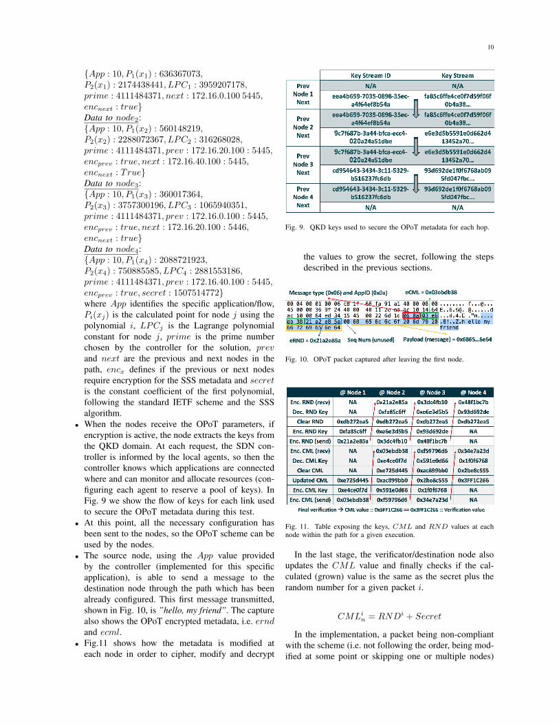
• When the nodes receive the OPoT parameters, ifencryption is active, the node extracts the keys fromthe QKD domain. At each request, the SDN con-troller is informed by the local agents, so then thecontroller knows which applications are connectedwhere and can monitor and allocate resources (con-figuring each agent to reserve a pool of keys). InFig. 9 we show the flow of keys for each link usedto secure the OPoT metadata during this test.
• At this point, all the necessary configuration hasbeen sent to the nodes, so the OPoT scheme can beused by the nodes.
• The source node, using the App value providedby the controller (implemented for this specificapplication), is able to send a message to thedestination node through the path which has beenalready configured. This first message transmitted,shown in Fig. 10, is ”hello, my friend”. The capturealso shows the OPoT encrypted metadata, i.e. erndand ecml.
• Fig.11 shows how the metadata is modified ateach node in order to cipher, modify and decrypt
Fig. 9. QKD keys used to secure the OPoT metadata for each hop.
the values to grow the secret, following the stepsdescribed in the previous sections.
Fig. 10. OPoT packet captured after leaving the first node.
Fig. 11. Table exposing the keys, CML and RND values at eachnode within the path for a given execution.
In the last stage, the verificator/destination node alsoupdates the CML value and finally checks if the cal-culated (grown) value is the same as the secret plus therandom number for a given packet i.
CMLin = RNDi + Secret
In the implementation, a packet being non-compliantwith the scheme (i.e. not following the order, being mod-ified at some point or skipping one or multiple nodes)

11
was directly dropped by the verificator. Nonetheless,this solution is also suitable with traditional networkingschemes and policies, so other actions could be alsotaken if the scheme fails on verifying the path.
The enhanced version shall not be very demanding interms of secret key updates. If the RND values are notrepeated for the same scheme and the random numbergeneration does not imply any additional security breach,the secret masks can be reutilized by the network ele-ments. In this sense, considering also the data providedby section 4 in the draft, in a 32 bit scheme with 100Gbps traffic chain, a scheme (set of polynomials) willlast for 22 seconds. Updating the masks every secondwill mean 22 updates per a given PoT scheme, meaninga secret key consumption of 64 bits per second (whichis negligible, based on the rates that can be provided bymodern QKD systems). The most demanding resourcewould be the random number generation which, as anexample, for a given 10Gbps traffic service, assuminga MTU of 1500, we will approximately have a total of840.000 packets per second. This implies a maximumgeneration of 27Mbps, which is multiplied by 10 for100 Gbps services. Other quantum services, as quantumrandom number generators [22], can be the source tocope with this demand, being installed in commoditydata centers.
VI. FUTURE WORK
The next steps for this research can be divided in two.The first would be from the standardization side, wherethe OPoT enhancement is being proposed in the newestversion of the IETF draft. This may require furtherwork in terms of datagram (e.g. dynamic rekeying syn-chronization for a given scheme using iOAM headers)and control plane definitions (extensions on the currentversion of the YANG models). The second will implyfurther research on the security implications of the PoTdefinition. This work is mainly focused on studying theoriginal assumptions of the PoT proposal, to demonstratethat the scheme could be bypassed using far less packetsthat initially stated. The attack is an illustrative exampleto show that the scheme is not applicable for the amountof data stated in the document. Additional performanceenhancements can be applied to the attack, as someparts are currently based on a ”brute force” approach(validating one to all), whilst some searchs and validationcould be parallelized.
In addition, the principles on which the MQN havebeen developed, fundamentally related to Software-Defined Networking, are being defined and standard-ized within the European Telecommunications Stan-dards Institute (ETSI), under the Industry SpecificationGroup on QKD. The model defined for abstractionand management of QKD resources will require several
incremental iteractions to include further use cases andbroader parametrization, as the QKD technology itself isdeveloped and standardized.
VII. CONCLUSIONS
Quantum key distribution networks are the key mea-sure for implementing quantum-safe communications.This work presents a security use case that is imple-mented on top of the recently deployed Madrid QuantumNetwork. In the context of virtualized services and nextgeneration protocols, new techniques for verifying thetraffic path/flow are necessary for security and otherreasons (e.g. legal interception). This work analyzes theIETF’s proposal for a proof-of-transit technique basedon Shamir’s Secret Sharing and its associates vulner-abilities. We find that the security is lower than ex-pected when using the standard method, and propose anenhancement that avoids the associated security threatswhile being compatible. The new scheme also providesorder, an important property to secure the network. Thisimprovement, based on symmetric encryption, is alsodemonstrated using a state-of-the-art technique, QKD,for providing secret keys and integrate them in thesystem. The use over a non-standard infrastructure high-lights the flexibility of the scheme and the fact that it canbe future-proofed even in the case of a major computingbreaktrough, like the availability of a quantum computer.The findings presented in this work have been presentedat the IETF and have been promoted as the preferredsolution for ordered proof-of-transit [23]. The presentedtechnique is implemented over the first QKD networkdeployed in a production environment and followingSDN principles.
ACKNOWLEDGMENT
The authors would like to thank the Spanish Min-istry of Economy and Competitiveness, for the grantCVQuCo, TEC2015-70406-R, FEDER-MINECO, theMadrid’s regional government, Comunidad Autonoma deMadrid, for the project Quantum Information Technolo-gies Madrid, QUITEMAD+ S2013/ICE-2801, the FETFlagship on Quantum Technologies, European UnionsHorizon 2020 research and innovation programme undergrant agreement No 820466: Continuous Variable Quan-tum Communications (CiViQ) and the team of Transportand IP Connectivity in Telefonica Spain for their supportto this activity.
REFERENCES
[1] E. Diamanti, H.-K. Lo, B. Qi, and Z. Yuan, “Practicalchallenges in quantum key distribution,” Npj QuantumInformation, vol. 2, p. 16025, 11 2016. [Online]. Available:http://dx.doi.org/10.1038/npjqi.2016.25

12
[2] V. Martin, J. Martinez-Mateo, and M. Peev, “Introduction toquantum key distribution,” in Wiley Encyclopedia of Electricaland Electronics Engineering, 2017, pp. 1–17. [Online]. Available:https://doi.org/10.1002/047134608X.W8354
[3] V. Martin, A. Aguado, P. Salas, A. Sanz, J. Brito, D. R.Lopez, V. Lopez, A. Pastor, J. Folgueira, H. H. Brunner,S. Bettelli, F. Fung, L. C. Comandar, D. Wang, A. Poppe, andM. Peev, “The madrid quantum network: A quantum-classicalintegrated infrastructure,” in OSA Advanced Photonics Congress(AP) 2019 (IPR, Networks, NOMA, SPPCom, PVLED). OpticalSociety of America, 2019, p. QtW3E.5. [Online]. Avail-able: http://www.osapublishing.org/abstract.cfm?URI=Networks-2019-QtW3E.5
[4] A. Aguado, V. Lopez, D. Lopez, M. Peev, A. Poppe, A. Pastor,J. Folgueira, and V. Martin, “The engineering of software-definedquantum key distribution networks,” IEEE Communications Mag-azine, vol. 57, no. 7, pp. 20–26, July 2019.
[5] A. Aguado, V. Lopez, J. Martinez-Mateo, T. Szyrkowiec, A. Aut-enrieth, M. Peev, D. Lopez, and V. Martin, “Hybrid conventionaland quantum security for software defined and virtualized net-works,” J. Opt. Commun. Netw., vol. 9, no. 10, pp. 819–825, Oct2017.
[6] A. Aguado, V. Lopez, J. Martinez-Mateo, M. Peev, D. Lopez,and V. Martin, “Vpn service provisioning via virtual routerdeployment and quantum key distribution,” in Proc. Optical FiberConference (OFC), 2018.
[7] ——, “Virtual network function deployment and serviceautomation to provide end-to-end quantum encryption,” J. Opt.Commun. Netw., vol. 10, no. 4, pp. 421–430, Apr 2018. [Online].Available: http://jocn.osa.org/abstract.cfm?URI=jocn-10-4-421
[8] C. Filsfils, S. Previdi, L. Ginsberg, B. Decraene, S. Litkowski,and R. Shakir, “Segment routing architecture,” RFC 8402, 2018.
[9] N. McKeown, T. Anderson, H. Balakrishnan, G. Parulkar, L. Pe-terson, J. Rexford, S. Shenker, and J. Turner, “OpenFlow: En-abling innovation in campus networks,” SIGCOMM Comput.Commun. Rev., vol. 38, no. 2, pp. 69–74, March 2008.
[10] “Network functions virtualisation (nfv); architectural frame-work,” in ETSI GS NFV 002 V1.2.1, 2014-12.
[11] J. Halpern and C. Pignataro, “Service function chaining (sfc)architecture,” RFC 7665, 2015.
[12] F. Brockners, S. Bhandari, S. Dara, C. Pignataro, J. Leddy,S. Youell, D. Mozes, and T. Mizrahi, “Proof of transit,” draft-ietf-sfc-proof-of-transit-00, 2018.
[13] M. Martinello, M. Ribeiro, R. de Oliveira, and R. de Angelis Vi-toi, “Keyflow: a prototype for evolving SDN toward core networkfabrics,” Network, IEEE, vol. 28, no. 2, pp. 12–19, March 2014.
[14] F. Rubina, “One-time pad cryptography,” Cryptologia, 1996.[15] F. Laudenbach, C. Pacher, C. F. Fung, A. Poppe, M. Peev,
B. Schrenk, M. Hentschel, P. Walther, and H. Hbel, “Continuous-variable quantum key distribution with gaussian modulation –the theory of practical implementations,” Advanced QuantumTechnologies, 2018.
[16] H. H. Brunner, L. C. Comandar, F. Karinou, S. Bettelli,D. Hillerkuss, F. Fung, D. Wang, S. Mikroulis, Q. Yi,M. Kuschnerov, A. Poppe, C. Xie, and M. Peev, “A low-complexity heterodyne cv-qkd architecture,” in 2017 19th Inter-national Conference on Transparent Optical Networks (ICTON),July 2017, pp. 1–4.
[17] F. Karinou, H. H. Brunner, C. F. Fung, L. C. Comandar, S. Bet-telli, D. Hillerkuss, M. Kuschnerov, S. Mikroulis, D. Wang,C. Xie, M. Peev, and A. Poppe, “Toward the integration of cvquantum key distribution in deployed optical networks,” IEEEPhotonics Technology Letters, vol. 30, no. 7, pp. 650–653, April2018.
[18] A. Shamir, “How to share a secret,” Communications of the ACM,vol. 22, no. 11, pp. 612–613, November 1979.
[19] F. Brockners, S. Bhandari, C. Pignataro, H. Gredler, J. Leddy,S. Youell, T. Mizrahi, D. M. anf P. Lapukhov, R. Chang,D. Bernier, and J. Lemon, “Data fields for in-situ oam,” draft-ietf-ippm-ioam-data-05, 2019.
[20] A. Menezes, P. C. van Oorschot, and S. A. Vanstone, Handbookof Applied Cryptography. CRC Press, 1996.
[21] M. N. Wegman and J. L. Carter, J. Comput. Syst. Sci., vol. 22,p. 265, 1981.
[22] M. Herrero-Collantes and J. C. Garcia-Escartin, “Quan-tum random number generators,” Rev. Mod. Phys.,vol. 89, p. 015004, Feb 2017. [Online]. Available:https://link.aps.org/doi/10.1103/RevModPhys.89.015004
[23] F. Brockners, S. Bhandari, S. Dara, C. Pignataro, J. Leddy,S. Youell, D. Mozes, T. Mizrahi, A. Aguado, and D. Lopez,“Proof of transit,” draft-ietf-sfc-proof-of-transit-02, 2019.