quality regulations for mechanical equipment edition
TRANSCRIPT

KBM 1(94)
2015-04-20, Edition 7.0
KBM QUALITY REGULATIONS
FOR
MECHANICAL EQUIPMENT
Edition 7.0, 2015-04-20
The Swedish Nuclear Power Companies have jointly produced this document. Any revision of this document must be approved by mutual consultation between the
companies.
Approved:
Anders Magnusson FKA, Erik Lindén OKG och Rasmus Waginder RAB
Licensee administrators of the PAKT-documents
ÖVS/G14/0001E edition 7 Enclosure 01 Sidan 1 av 170

KBM 2(94)
2015-04-20, Edition 7.0
TABLE OF CONTENTS 0 INTRODUCTION .......................................................................................... 7 0.1 Background ................................................................................................. 7 0.2 Objective ...................................................................................................... 7 0.3 Application .................................................................................................. 7 0.3.1 Surface treatment ......................................................................................... 7
1 GENERAL REQUIREMENTS FOR QUALITY AND AUTHORISATION ..... 8 1.1 General ........................................................................................................ 8 1.1.1 Area of application ........................................................................................ 8 1.2 Definitions and Abbreviations ................................................................. 10 1.3 General Quality and Inspection Regulations ......................................... 12 1.3.1 General Regulations – the purchaser’s and supplier’s Commitment .......... 12 1.3.2 Regulations, Codes and Standards ............................................................ 13 1.3.3 Design specifications and design criteria .................................................... 13 1.3.4 Division into Quality Classes ...................................................................... 14 1.3.5 Documentation for Manufacturing, Installation or Repair ............................ 14 1.3.6 General Inspection Requirements, Procedures and Descriptions .............. 14 1.3.7 Materials ..................................................................................................... 15 1.3.8 Manufacturing Inspection ............................................................................ 15 1.3.9 Inspection of Installation and Repair of Deficiency in the Nuclear Plant ..... 16 1.3.10 Deviations ................................................................................................... 16 1.3.11 Documentation ............................................................................................ 16 1.4 Requirements on manufacturers Quality Assurance and Accreditation18 1.4.1 General ....................................................................................................... 18 1.4.2 Quality System and Quality Plans .............................................................. 18 1.4.3 Accreditation ............................................................................................... 19 1.4.3.1 Requirements for Accredited Body in the position of third party ................. 19 1.4.3.2 Requirements for Accredited Laboratories in the position of third party within
Sweden ....................................................................................................... 19 1.4.3.3 Requirements for Accredited Laboratories in the position of third party in a
foreign country ............................................................................................ 19 1.4.3.4 Requirements for Accredited Inspection Body and Certification Body in the
position of third party within Sweden .......................................................... 20 1.4.3.5 Requirements for Accredited Inspection Body and Certification Body in the
position of third party in a foreign country ................................................... 20 1.4.3.6 Requirements concerning Notified Body .................................................... 20 1.4.4 Assessment of Supplier .............................................................................. 21 1.4.4.1 Assessment ................................................................................................ 21 1.4.4.2 Register of suppliers ................................................................................... 21 1.5 Rules for Type Inspection Certificate ..................................................... 21 1.5.1 General ....................................................................................................... 21 1.5.2 Scope .......................................................................................................... 22 1.5.3 Obtaining of Type Inspection Certificate ..................................................... 22 1.5.4 Purchasing according to Type Inspection Certificate .................................. 22 1.5.5 Documentation ............................................................................................ 22 1.6 Authorisation for Welding and other Joining Methods ......................... 22 1.6.1 General ....................................................................................................... 22 1.6.2 Authorisation requirements for manufacturers and welding companies ..... 22 1.6.3 Requirements for qualification of welding procedure .................................. 23 1.6.4 Requirements for certification of welders .................................................... 24 1.6.5 Personnel qualification for welding at installation and repair ...................... 25 1.7 Licensee’s approval of companies performing heat treatment at
manufacture and installation ................................................................... 26 1.7.1 General ....................................................................................................... 26 1.7.2 Authorisation requirements ......................................................................... 26 1.7.3 Scope .......................................................................................................... 26
ÖVS/G14/0001E edition 7 Enclosure 01 Sidan 2 av 170

KBM 3(94)
2015-04-20, Edition 7.0
1.8 Authorisation for testing and inspection ................................................ 26 1.8.1 Authorisation to act as an Accredited Laboratory, Accredited Certification or
Inspection Body .......................................................................................... 26 1.8.2 General for authorisation for testing and inspection ................................... 26 1.8.2.1 Description of well proven NDT system according to general recommendations
to SSMFS 2008:13 ..................................................................................... 27 1.8.3 Authorisation for testing at manufacturing of material and shapes ............. 27 1.8.4 Authorisation for testing at manufacture of mechanical equipment ............ 27 1.8.5 Authorisation for NDT at installation and repairs of installed equipment .... 28 1.9 Other competencey requirements........................................................... 28 1.9.1 Installation of pipe couplings ....................................................................... 28 1.9.2 Installation of fasteners in concrete ............................................................ 28 1.10 Re-qualification of stored equipment ..................................................... 28
2 GENERAL INSPECTION REQUIREMENTS AND INSPECTION PROCEDURES .......................................................................................... 29
2.1 Description of general inspection requirements and inspection procedures ................................................................................................ 29
2.1.1 General ....................................................................................................... 29 2.1.2 General inspection requirements, division and content .............................. 30 2.1.2.1 Division and content ................................................................................... 30 2.1.2.2 Inspection prior manufacturing, installation or repair of installed equipment30 2.1.2.3 Inspection of base material and shapes ..................................................... 30 2.1.2.4 Inspection at manufacturing, welding and other joining .............................. 31 2.1.2.5 Inspection of completed equipment or sub-assemblies .............................. 32 2.1.2.6 Inspection of completed installation or repair of installed equipment .......... 33 2.1.3 Descriptions of the inspection procedures .................................................. 33 2.1.4 Designations for extent of inspection and supervision ................................ 34 2.1.5 Scope of the inspection .............................................................................. 35 2.1.5.1 Scope of prescribed inspection ................................................................... 35 2.1.5.2 Distribution of random inspection ............................................................... 35 2.1.5.3 Extension of inspection ............................................................................... 36 2.1.5.4 Extension of inspection when pressure and tightness test is not performed36 2.1.6 Abbreviations for NDT Methods .................................................................. 37 2.1.7 Certificate of Compliance ............................................................................ 37 2.1.7.1 Basic regulations – Conditions for use ....................................................... 37 2.1.7.2 The scope of activities to be performed by an Accredited Inspection Body
according to SSMFS 2008:13, 5 chapt. 2§ in order to issue Certificate of Compliance ................................................................................................. 37
2.1.7.3 Scope of inspection in quality class 4 according to SSMFS (SSM supervising authority) ..................................................................................................... 38
2.1.7.4 Scope of inspection outside SSMFS (Arbetsmiljöverket, AV, as supervising authority) ..................................................................................................... 38
2.1.7.5 Co-operation between licensee and Accredited Inspection Body ............... 38 2.1.8 Register of applicable regulations, codes and standards ........................... 39 2.2 Listing of general inspection requirements ........................................... 43 2.2.1 General inspection requirements prior to manufacture, installation and repair
.................................................................................................................... 43 2.2.2 Pressure-retaining equipment or components ............................................ 43 2.2.3 General inspection requirements at manufacture, welding and other joining44 2.2.4 General inspection requirements for completed mechanical equipment or part
of device ..................................................................................................... 44 2.2.5 General inspection requirements – installation or repair ............................. 44 2.2.6 General inspection requirements – Installed system or part of system or repair
.................................................................................................................... 44 2.3 Listing of applicable inspection procedures .......................................... 45 2.3.1 Descriptions of inspection procedures – Prescribed or inspection and testing
according to code ....................................................................................... 45
ÖVS/G14/0001E edition 7 Enclosure 01 Sidan 3 av 170

KBM 4(94)
2015-04-20, Edition 7.0
2.3.2 Descriptions of inspection procedure – Other inspection and testing ......... 46
3 INSPECTION PRIOR TO MANUFACTURING, INSTALLATION AND REPAIR OF INSTALLED EQUIPMENT ................................................................... 47
3.1 General inspection requirements prior to manufacturing and installation IP-100 – IP-102 ........................................................................................... 47
3.1.1 General inspection requirements prior to manufacturing and installation IP-100 .................................................................................................................... 47
3.1.2 General inspection requirements prior to manufacturing and installation IP-101 .................................................................................................................... 49
3.1.3 General inspection requirements prior to manufacturing and installation IP-102 .................................................................................................................... 51
3.2 General inspection requirements prior to repairs of mechanical equipment - IP-103 .................................................................................... 52
3.2.1 General inspection requirements prior to repair of deficiencies induced by plant operation - IP-103 ....................................................................................... 52
3.3 Inspection specification – Inspection prior to manufacturing, installation or repair of installed equipment. ............................................................. 54
3.3.1 Introduction ................................................................................................. 54 3.3.2 Documentation to be prepared by the purchaser or licensee ..................... 54 3.3.2.1 Description and/or report, with conditions for action to be taken ................ 54 3.3.2.2 Design specifications .................................................................................. 54 3.3.2.3 Supplier assessment .................................................................................. 55 3.3.2.4 Updating of flow charts ............................................................................... 55 3.3.2.5 Updating of classification lists ..................................................................... 55 3.3.2.6 Basic repair documentation ........................................................................ 55 3.3.3 Documentation to be prepared by the supplier or manufacturer ................. 56 3.3.3.1 Supplier assessment of sub-contractors ..................................................... 56 3.3.3.2 Quality plan for installation and repairs of installed equipment ................... 56 3.3.3.3 Design review ............................................................................................. 56 3.3.3.4 Review of detailed inspection documentation ............................................. 58 3.3.3.5 Review of the company’s welding authorisation ......................................... 59 3.3.3.6 Review of the company’s heat treatment authorisation .............................. 59 3.3.3.7 Review of the company’s NDT authorisation .............................................. 59 3.3.3.8 Review of documentation for removal of service induced deficiencies ....... 60 3.3.3.9 Review of documentation for repair of service induced deficiencies, normally
welding ........................................................................................................ 60
4 MANUFACTURE INSPECTION ................................................................. 61 4.1 General material inspection requirements IP-200 ................................. 62 4.1.1 Pressure retaining equipment or parts thereof – IP 201 to 209 .................. 62 4.1.2 Load bearing equipment and equipment parts – IP 221 to 222 .................. 77 4.1.3 Internal parts in mechanical equipment – IP 230 ........................................ 79 4.1.4 Internals in reactor pressure vessels and Steam Generators – IP 240 ...... 80 4.2 General inspection requirements – Manufacture/Joining – IP 300 ...... 81 4.2.1 Mechanical equipment and parts thereof – IP 300 ..................................... 81 4.3 General inspection requirements – Finished mechanical equipment or
subassembly IP 400 ................................................................................. 85 4.3.1 Finished mechanical equipment or subasembly – IP 400 ........................... 85
5 INSTALLATION AND REPAIR INSPECTION ........................................... 92 5.1 General requirements – Installation or repair IP-500 ............................. 92 5.1.1 Testing and inspection at welding ............................................................... 92 5.1.2 Other inspection at installation .................................................................... 92 5.2 General inspection requirements – Installed system or part of system or
repair IP-600 ............................................................................................. 94 5.2.1 Pipes and piping ......................................................................................... 94 5.2.2 Load bearing equipment in pipe systems ................................................... 94 5.2.3 Quality Control Documentation ................................................................... 94
ÖVS/G14/0001E edition 7 Enclosure 01 Sidan 4 av 170

KBM 5(94)
2015-04-20, Edition 7.0
APPENDIX:
Appendix 1 Description of inspection procedures (compulsory inspection)
Appendix 2 Description of inspection procedures (other inspection)
ÖVS/G14/0001E edition 7 Enclosure 01 Sidan 5 av 170

KBM 6(94)
2015-04-20, Edition 7.0
LIST OF REVISIONS – KBM
Edition Reason for revision Applicable pages Date
2 Thorough revision due to the regulations issued by the Swedish nuclear power inspectorate regarding revision of ”the regulations (SKIFS 1994:1) Mechanical Equipment in Nuclear Plants”, SKIFS 1996:1 and revisions due to aspects from review of issue 1 performed by licensees and SAQ Nuclear Engineering Inspection Limited
Revision of the entire document
1997-05-01
3 Thorough revision The entire document 1999-10-01
4 Thorough revision due to SKIFS 2000:2 and aspects from the licensees and DNV Nuclear Technology
The entire document 2001-04-01
5 Thorough revision due to SKIFS 2005:2 and gained experiences.
The entire document 2008-01-08
6.0 General update The entire document 2011-02-15
7.0 General update The entire document See markings
2015-04-20
ÖVS/G14/0001E edition 7 Enclosure 01 Sidan 6 av 170

KBM 7(94)
2015-04-20, Edition 7.0
0 INTRODUCTION
0.1 Background
The PAKT documents (PBM1, PBM2, ABM, KBM, TBM, TBV and PAKT list of definitions) shall be updated on periodically basis. At the revisions new standards and experiences gained to be implemented into the documents.
Quality Regulations for Mechanical Equipment “KBM” is an implementing document jointly created by the Swedish nuclear power licensees and this document constitutes a common interpretation in order to fulfil:
The requirements of the regulation SSMFS 2008:13 issued by the Swedish Radiation Safety Authority
The requirements of the regulations AFS 1999:4, AFS 1993:41 (rewritten in AFS 1994:53) and AFS 2005:2 upon design and manufacturing of pressurised equipment. These regulations are issued by the Occupational Safety and Health Board.
The licensee’s own requirements, and
The level of testing, inspection and reporting considered necessary by the licensees for an Accredited Inspection Body to certify the conformance with the requirements in SSMFS 2008:13.
This regulation can also be used as guideline for other applications than those included above.
0.2 Objective
The objective with KBM is that the licensees shall use the regulations for:
Purchasing of mechanical equipment
In-house manufacturing of mechanical equipment,
Purchasing of installations and repairs,
Installations or repairs under own management.
0.3 Application
KBM shall be used together with the licensee’s common technical regulations, TBM and TBV. In addition, when the equipment also contains electrical parts, technical regulations, TBE, and inspection regulations, KBE, for electrical equipment shall be used. Unless specific issue of standard is specified as applicable, the latest issue, alternatively, new standard replacing the obsolete standard to be applied. The licensee shall however always approve new standards.
0.3.1 Surface treatment
For surface treatment, there are common technical regulations in TBM.
ÖVS/G14/0001E edition 7 Enclosure 01 Sidan 7 av 170

KBM 8(94)
2015-04-20, Edition 7.0
1 GENERAL REQUIREMENTS FOR QUALITY AND AUTHORISATION
1.1 General
These quality regulations constitute a joint implementation document for the Swedish licensees. The purpose of the document is to interpret The Swedish Radiation Safety Authority (SSM) regulations regarding mechanical parts in certain nuclear plants, SSMFS 2008:13.
Mechanical equipment in any of the quality classes 1-4 or 4A shall be designed, manufactured, installed and inspected according to SSMFS 2008:13, 4th chapter, 4-12 §§.
For design and manufacturing of pressure retaining devises in quality class 4, where deficiencies or malfunction not can cause discharge of radioactive substances the regulations AFS 1999:4 (PED), AFS 1993:41 (rewritten in AFS 1994:53) and AFS 2005:2 issued by the Swedish Work Environment Inspection are valid. In addition SSMFS 2008:13, 4th chapter, 4§ along with the licensee’s possible additional requirements to be considered.
For design and manufacturing of pressure retaining devises in quality classes 4 where deficiencies or malfunction can cause discharge of radioactive substances the regulation SSMFS 2008:13 is valid. The extent of inspection and testing shall correspond to quality class 3. The extent of structural verification in quality class 4A and systemes in quality class 4 with risk of radioactive discharge shall correspond to the extent of quality class 4 inspection class A-B.
The Accredited Inspection Body’s (AIB) participation at inspection and testing of installation, repairs, exchanges, modifications and extension of equipment is governed by the inspection class divisioning as per AFS 2005:3. In inspection class A-C, AIB participates to necessary extent to issue certificate of conformity (IOÖ). For installations in quality class 4A, the same extent of inspection and testing as for quality class 4 inspection class A-B applies.
Changes of a nuclear plant's operational conditions, including increase of the power, are in terms of requirements regarded as physical plant changes.
1.1.1 Area of application
The Nuclear Plants affected by these regulations are:
Forsmark 1, 2 and 3
Oskarshamn 1, 2 and 3
Ringhals 1, 2, 3 and 4
The quality regulations apply to design and manufacturing of such mechanical equipment being part of the primary system or in the containment barrier or in the safety, operational and auxiliary systems in nuclear plant reactors. The quality regulations also apply to mechanical equipment for reactivity control and maintaining of criticality safety.
The quality regulations do not apply to:
moving machine internals in pumps, turbines, motors and generators
lifting equipment and lifting tools
ÖVS/G14/0001E edition 7 Enclosure 01 Sidan 8 av 170

KBM 9(94)
2015-04-20, Edition 7.0
mechanical parts in nuclear fuel clusters
containers used for transport of nuclear substances and nuclear waste
mechanical equipment used for handling, processing, storing or final disposal of nuclear waste along with such containers intended for nuclear waste
The Quality Regulations are neither valid for:
Atmospheric tanks intended for inflammable liquid, for which regulations have been issued with support of the regulation (SFS 2010:1075) regarding inflammable and explosive goods
Piping for inflammable liquid for which regulations have been issued, supported by the regulation regarding inflammable goods, and which are used between components that are neither pressure vessels nor vacuum vessels
Such mechanical equipment being integrated parts of a reactor containment
The regulations can in applicable parts be used as guidance for the preparation of documents for mechanical equipment not formally included in the regulations.
For requirements on atmosperic storage tanks and piping for flammable liquids, see MSBFS 2014:5 and BFS 2013:10. For requirements on other atmospheric storage tanks, see AFS 2005:2 and BFS 2013:10. For safety related atmospheric storage tanks in quality class 2-3 also inspection requirements as per ASME to be regarded. For core reactivity control equipment extent of inspection and testing corresponding to quality class 2 should be applied for boiling water reactors and for pressurised water reactors should requirements corresponding to quality class 3 be applied.
ÖVS/G14/0001E edition 7 Enclosure 01 Sidan 9 av 170
KBM 10(94)
2015-04-20, Edition 7.0
1.2 Definitions and Abbreviations
For the “PAKT documents” (PBM1, PBM2, ABM, TBM and KBM) the licensees have jointly produced a list of definitions that is presented in a separate document “PAKT definitions”.
Abbreviations
In these regulations the following abbreviations are used:
ABM General Regulations for Mechanical Equipment
AFS The Swedish Work Environment Authority’s Statue Book
AV The Swedish Work Environment Authority
AIB Accredited Inspection Body according to SSMFS (see AK)
AIS Guidelines for non-mechanical safety equipment, Issued by the Pressure Vessel Standardisation
AK Accredited Inspection Body according to SSMFS, also “AIB”
AL Accredited Testing Laboratory
AO Notified Body according to AFS accredited according SS-EN ISO/IEC 17020
ANS American Nuclear Society
ANSI American National Standards Institute
ASME The American Society of Mechanical Engineers
BFS Statutes of National Board of Housing, Building and Planning
BWR Boiling Water Reactor
bk Inspection class, also “ic”
CFR Codes of Federal Regulations
DN Nominal size according to SS-EN ISO 6708
DUP Detailed Ultrasonic Testing Procedure
HAZ Heat Affected Zone
HVAC Heating Ventilation Air Condition
IGSCC Intergranular Stress Corrosion Cracking
ic Inspection class (see “bk”)
ISI In-Service Inspection
KBM Quality Regulations for Mechanical Equipment
KFM Mechanical Design Criteria
KO Qualification Body
ÖVS/G14/0001E edition 7 Enclosure 01 Sidan 10 av 170

KBM 11(94)
2015-04-20, Edition 7.0
KTA Der Kerntechnishe Aussuchuss
LOCA Loss of Coolant Accident
MSBFS Statutes of Swedish Civil Contingencies Agency
NDT Non-destructive test
NPS Nominal Pipe Size
PAKT Common abbreviation for the documents PBM1, PBM2, ABM, KBM, TBM, TBV and the PAKT list of definitions
PBM Regulations for In-service inspection
PED Pressure Equipment Directive, 97/23/EG
PWR Pressurised Water Reactor
RCPB Reactor Coolant Pressure Boundary
SAR Safety Analysis Report
SG Steam Generator
SIS Swedish Standards Institute
SSMFS The Swedish Radiation Safety Authority Regulations
STAFS Statute-book of The Board of Technical Inspection
SWEDAC The Board for accreditation and technical inspection
TBM Technical Regulations for Mechanical Equipment
TBV Technical Regulations for Ventilation Equipment
TH Licensee (of Nuclear Facility)
TM Technical Justification
ÖVS/G14/0001E edition 7 Enclosure 01 Sidan 11 av 170

KBM 12(94)
2015-04-20, Edition 7.0
1.3 General Quality and Inspection Regulations
1.3.1 General Regulations – the purchaser’s and supplier’s Commitment
The purchaser shall furnish documentation for the supplier’s undertaking by specifying the requirements through the following documents:
Technical Regulations – TBM and TBV
Quality Regulations - KBM
Information regarding relevant quality class, and when applicable, function class
General inspection requirements including related inspection procedures
Other requirements related to components
The purchaser shall ensure that the relevant quality control documents satisfies and complies with the relevant authority requirements.
Unless otherwise specified, the purchaser shall defray all costs related to third party review made by an Accredited Inspection Body and he shall also ensure that it is ordered.
The supplier shall, unless otherwise specified, defray all costs related to all other third party inspection from used Accredited Laboratory and Accredited Bodies during manufacturing and installation.
The supplier shall, unless otherwise specified, defray the costs related to third party inspection, caused by repairs, repeated inspections, processing of deviations or and/or down-time caused by the supplier during manufacturing and installation.
The supplier shall ensure that detailed manufacturing- and inspection documentation is prepared and sent to the purchaser for review and approval.
Unless otherwise agreed, the purchaser is responsible for the review by the Accredited Inspection Body.
The supplier shall ensure that all approved documentation for manufacturing and inspection is listed in a separate document, stating the title and valid version of the approved documents. The list of approved documents shall be kept up to date by the supplier and be included in the final quality control documentation.
The supplier shall be responsible and administer the inspection and records that are required in accordance with the approved manufacturing and inspection documentation. The supplier shall notify the Accredited Inspection Body whenever stated in the inspection documentation.
The supplier shall carry out and defray all inspection necessary for assuming full responsibility for the quality of the product.
Suppliers shall possess and follow a well-recognised quality assurance system, see.1.4.2.
For manufacturing, installation and repair in quality class 1-3 and function class 1E, the supplier shall be assessed and approved according to 1.4.
ÖVS/G14/0001E edition 7 Enclosure 01 Sidan 12 av 170
KBM 13(94)
2015-04-20, Edition 7.0
The purchaser shall be entitled to attend the supplier’s inspection work without cost and also to carry out his own inspections.
The purchaser shall be entitled to participate, on special request, in discussions of inspection matters that are held between the supplier and inspection companies and subcontractors engaged by him.
Approval obtained from the purchaser and engaged inspection companies does not exempt the supplier from contractual obligations and liability for the quality of the product.
The supplier must be prepared, on special order, to carry out additional inspection above and beyond the original agreement. The supplier shall give the purchaser the name of the person he has put in charge of the inspection work.
The supplier shall, on the purchaser’s request, report the result of his assessments of the subcontractors.
1.3.2 Regulations, Codes and Standards
The supplier and the purchaser shall commonly agree to the standards, codes and regulations that shall apply for the order. Both parts shall approve possible deviations from the agreement at the time of ordering and if applicable, be approved/reviewed by prescribing authority or AIB.
1.3.3 Design specifications and design criteria
The design specification and design criteria (KFM) thereto shall in connection with ordering of replacement equipment, installation work or repairs, be established by the licensee. The supplier of certain designs shall whenever agreed in the purchase order provide basis and in-data necessary for the licensee’s preparation of design specifications and design criteria.
For installation of equipment in quality classes 1-4, 4A where SSMFS 2008:13, 4th chapter, 4§ is applicable, the design criteria included in the design specifications shall be safety reviewed and notified to the Swedish Radiation Authority (SSM). The notification shall be responded by SSM prior to the Accredited Body’s issuance of certificate of compliance as per the requirements of SSMFS 2008:13.
For the design of replacement parts, that are mainly identical to the parts intended to be replaced, design verification could be performed by demonstrating that the replacement parts, as a minimum, fulfils the original strength requirements.
At work where the design criteria remain unaltered, the design criteria in force including the reply from SSM shall be reported to the assigned Accredited Inspection Body.
Further details regarding design specifications and design criteria are to be found in Technical Regulations – TBM.
ÖVS/G14/0001E edition 7 Enclosure 01 Sidan 13 av 170

KBM 14(94)
2015-04-20, Edition 7.0
1.3.4 Division into Quality Classes
The division in quality classes governs the design requirements and quality assurance measures for mechanical equipment.
For each respective nuclear plant the division into quality classes is evident from the flow charts and classification lists that are based on requirements and principles in the nuclear plant specific Safety Analysis Report (SAR) for each plant. These requirements and principles for the divisioning into quality classes shall be notified to and accepted by SSM for each nuclear plant.
Division into electrical function classes is evident from each nuclear plant’s classification lists in force.
At nuclear plant modifications where new systems or parts of systems are added, these will be classified according to the requirements and principles in the Safety Analysis Report (SAR) for each plant.
For further details regarding safety- and quality classification, see TBM.
1.3.5 Documentation for Manufacturing, Installation or Repair
Before starting manufacturing, installation or repair of deficiencies in the nuclear plant, the supplier shall furnish the purchaser with applicable documents such as drawings, calculations, procedures, procedure qualifications, inspection documentation etc. for review and approval (for a more detailed description of the required documentation see section 3).
The documentation shall be based on and include the data requested according to the technical regulations (TBM) and quality regulations (KBM), specified by the purchaser.
Unless otherwise agreed, the purchaser / licensee shall after his approval be responsible that the documentation, to the required extent, is third party-reviewed by an Accredited Inspection Body.
1.3.6 General Inspection Requirements, Procedures and Descriptions
The supplier shall transfer relevant and applicable inspection requirements into detailed inspection documents (inspection plan) for the manufacturing, installation and repair of deficiencies in the nuclear plant. The inspections and tests that are considered necessary by the supplier to achieve full responsibility shall also be included.
The supplier shall further prepare written procedures in the cases this is prescribed in these regulations or in the purchase order. The written procedures shall fulfil and include the data, which is requested in the description of the inspection procedures included in these regulations (KBM).
In the cases where procedure qualification is reguired, the qualification reports shall be enclosed.
For more detailed description of the necessary documentation, see chapter 3.
Before the work is initiated, above mentioned documentation shall be reviewed and approved by the purchaser.
ÖVS/G14/0001E edition 7 Enclosure 01 Sidan 14 av 170
KBM 15(94)
2015-04-20, Edition 7.0
After the purchaser has approved the documentation, he shall, unless otherwise agreed, arrange that the documentation will be third party-reviewed by an Accredited Inspection Body.
Deviation from the requirement of preparing detailed quality control documentation and written procedures is not allowed without a written permission from the purchaser. The supplier is responsible to apply for such permission from the purchaser.
1.3.7 Materials
Material shall be selected in accordance with applicable regulations, agreement, and/or directions in the purchaser’s Technical Regulations -TBM.
The supplier shall ensure that testing, inspection, marking and documentation of material is carried out to the extent and in accordance with the procedures stipulated in the approved inspection documentation.
The supplier is responsible for the marking to be transferred in such a manner that all identification of material against relevant inspection reports will be ensured.
The supplier shall ensure that the material’s dimensions and surface finish meets the requirements that are specified in codes and technical regulations and otherwise conform to the requirements of the purchaser.
Repair of parent metal, by welding is only permitted after written consent from the purchaser. If repair by welding is accepted by the purchaser, a procedure for repair shall be prepared, in which requirements for testing, inspection, welding procedure, welding procedure qualification, possible heat treatment and other requirements shall be specified.
The procedure shall be reviewed and approved by the purchaser and if applicable also by AIB before commencement of the repair is permitted.
1.3.8 Manufacturing Inspection
Prior to the start of manufacture, the supplier shall check that drawings, inspection plans and other relevant documents are reviwed and approved by the purchaser and in applicable cases by AIB. The supplier’s inspection plans shall be prepared in such a way that produced items and sub assemblies may be approved prior to installation and that associated certificate from AIB and licensee is issued prior to the installation.
The supplier and the purchaser shall upon order agree who to order, pay for and suborder a possible third-part examination. This is also valid for who shall pay for a possible re-inspection.
The supplier is responsible for submitting notification for manufacturing inspection in due time as agreed in the order.
Unless otherwise stated, the supplier shall be responsible for and pay for all testing and inspection according to the approved inspection plan and also be responsible for the documentation thereto.
During ongoing manufacturing, the supplier shall furnish the purchaser with the documents requested by the purchaser needed to follow the manufacturing.
ÖVS/G14/0001E edition 7 Enclosure 01 Sidan 15 av 170
KBM 16(94)
2015-04-20, Edition 7.0
The purchaser shall inspect the final product and the documentation therto to be reviwed and approved by the purchaser. If, for reasons of access, the equipment cannot be inspected at a later time, the supplier shall contact the purchaser and agree on a suitable time for inspection.
If so required, inspection and review of inspection records shall also be performed by an Accredited Inspection Body prior to the installation of the equipment in the nuclear plant. This can after agreement with AIB either be performed as a delivery inspection at the supplier’s facilities or as a site receiving inspection at the nuclear plant.
1.3.9 Inspection of Installation and Repair of Deficiency in the Nuclear Plant
Prior to start of installation or repair of deficiency, the governing inspection documents to be approved by the purchaser and in applicable cases by AIB.
The supplier and the purchaser shall upon order, agree who shall order, pay for and suborder possible third party inspection. This is also valid for whom to pay for possible re-inspection.
1.3.10 Deviations
The supplier shall obtain the purchasers written approval of any deviations from the KBM and TBM requirements, or by the purchaser previously approved documentation or other requirements stated in the order.
After the review and possible approval of the deviation, the purchaser applies for any disposition that may be required by authorities and the Accredited Inspection Body.
In the deviation report, the supplier shall clearly describe the nature of the deviation and suggest corrective action.
The supplier shall also report the corrective actions he considers to take for preventing recurrence.
The deviation report shall be issued and signed in accordance with the supplier’s quality assurance system.
All deviations shall be processed, corrected and approved before the relevant work operations are finalised.
The supplier shall ensure that all the deviations are currently registered.
Deviation reports shall be included in the final quality control documentation.
Unless otherwise agreed, the supplier is responsible for all the inspection costs related to deviations caused by the supplier.
1.3.11 Documentation
The supplier shall in a clear manner compile records for the review, testing and inspection included in the order and stipulated in the inspection plans.
A document list shall be included and contain:
Governing documentation for manufacturing
ÖVS/G14/0001E edition 7 Enclosure 01 Sidan 16 av 170
KBM 17(94)
2015-04-20, Edition 7.0
Documentation for manufacturing
Applicable certificates and reports prepared during the work
Any deviation reports
The supplier shall ensure that the final documentation package such as drawings, inspection plans, procedures, qualification programmes, qualification reports, test reports, certificates etc, are signed and approved by the manufacturer.
The documentation shall be signed by the purchaser or his representative and/or the Accredited Inspection Body to the extent prescribed in the inspection plan.
The supplier shall ensure that certificates are traceable against the inspection plan and the item to which the certificate pertains. The certificates can be made traceable against the inspection plan by specification of a consecutive number on the certificate. This consecutive number is noted in the inspection plan for the inspection activity and item to which the certificate pertains.
It must be evident that the manufacturer has reviewed and approved the quality control documentation.
The supplier shall also certify that the product and the executed work is approved and fulfils the requirements of the supplier and the purchaser.
At manufacturing of material and components the purchaser shall in cooperation with the supplier ensure that the Accredited Inspection Body issues certificates of compliance with the requirements according to the inspection plans.
The supplier shall file radiographs and other testing and manufacturing records for material and components in an expedient manner and keep them available to the purchaser for at least 10 years after delivery. If the supplier must discontinue the filing, the purchaser shall be notified, even after the 10-year period. Alternatively, radiographs and documents may be turned over to the purchaser for filing.
Unless otherwise agreed, the supplier shall provide the purchaser with the quality control documentation when materials and components are delivered.
After the installation or repair work, the supplier shall turn over the quality control documentation to the purchaser for approval and filing.
The supplier shall state that he has inspected the installation according to the drawings and reviewed and approved the quality control documentation.
The purchaser shall at the receipt inspection of material and components review and approve the quality control documentation, submitted by the supplier.
As an alternative to receipt inspection, material and components can be approved by the purchaser as delivery inspection at the manufacturer.
Prior to installation in the nuclear plant or if possible prior to turn over to storage, inspection and review of inspection records shall whenever required also be performed by an Accredited Inspection Body.
ÖVS/G14/0001E edition 7 Enclosure 01 Sidan 17 av 170

KBM 18(94)
2015-04-20, Edition 7.0
The purchaser shall whenever required, after his own review and approval of the installation or repairs arrange that an appointed, Accredited Inspection Body can issue a certificate of compliance with the stipulated requirements.
1.4 Requirements on manufacturers Quality Assurance and Accreditation
1.4.1 General
The Swedish licensees have established a common system for assessment of suppliers. The requirements for quality assurance have hereby been formalised to enable every single licensee to apply the same or equal requirements on the supplier’s quality system.
For quality class 1-3 methods and procedures for performing and reporting of assessment of the suppliers shall be common between the licensees in order to wherever applicable fulfil the IAEA codes and guidelines for quality assurance of the safety in the nuclear plants and other nuclear plants, IAEA Safety series No 50-C/SG-Q. (See SSMFS 2008:13 General advices to 5 chap 3§).
Reports from performed quality audits are submitted to the other licensees. Reports received from other licensees are evaluated and approved for own use providing that the audit contains the requirements stipulated for their own nuclear plants.
The data from this register is only available to the licensee’s authorized staff.
1.4.2 Quality System and Quality Plans
The suppliers and their subcontractors shall have and follow a quality assurance system that meets the requirements in applicable parts of SS-EN ISO 9000 series, or another equal, acknowledged standard. When additional quality plans are required for specific projects, these are to follow the guidelines of SS-ISO 10006 ”Quality management systems – Guidelines for quality management in projects” or similar.
For supplier performing welding shall the quality system in addition contain the requirements of ISO-3834-2.
The above requirement is applicable at purchasing of material, shapes, mechanical equipment, components and services, as well for single parts thereof as for total commitments in quality class 1-4.
The following documents shall to applicable extent be submitted to the purchaser:
A copy of the supplier’s certification of the quality system.
A copy of possible subcontractor’s certificates of certifying their quality systems.
A copy of the certificate or type approval certificate, issued by Accredited Certification Body or Accredited Inspection Bodies.
Essential changes within the organisation and routines of the company which can affect the quality shall be reported to the purchaser, this applies to the entire time for duration of the purchaser’s approval of the supplier.
ÖVS/G14/0001E edition 7 Enclosure 01 Sidan 18 av 170

KBM 19(94)
2015-04-20, Edition 7.0
1.4.3 Accreditation
General:
"Certificate of compliance with the stipulated requirements” is issued by an Accredited Inspection Body that is accredited according to the SSM regulations.
Testing in the course of repairs of deficiencies in the nuclear plant, installation and in service inspection shall be carried out by an Accredited Testing Laboratory in the position of third party.
Testing in the course of manufacturing shall be performed by an Accredited Testing Laboratory or as in-house inspection randomly supervised by an Accredited Body, A, L or K depending on the type of testing. (Symbols for inspection and testing are defined under 2.1.4). Executing staff shall fulfil the requirements according to 1.8.4. For testing in the course of manufacturing according to PED in quality class 4 can NDT performed by staff with competence according to SS-EN ISO 9712 be accepted.
Providing that the manufacturer applies a quality system, certified by an Accredited Body in the position of third party, for the testing activities, testing in conjunction with manufacturing of material and shapes can be performed as in-house inspection.
In Sweden pressure testing with gas requires accreditation according to AFS 2006:8.
Testing as above is defined as non destructive testing (NDT) and mechanical testing of material.
1.4.3.1 Requirements for Accredited Body in the position of third party
Accredited bodies in the position of third party are defined as bodies performing certification or inspection services and laboratories performing testing assignments.
A copy of the certificate of accreditation issued by SWEDAC or similar foreign authority shall be sent to the purchaser.
1.4.3.2 Requirements for Accredited Laboratories in the position of third party within Sweden
Testing Laboratories performing prescribed NDT and services at material laboratories shall be accredited by SWEDAC for the activities in question. In addition, for testing in the course of installation, repair of deficiencies and in service inspections, these Testing Laboratories shall be accredited in the position as a third party.
Laboratories accredited by SWEDAC for testing in the course of repair of installed equipment and installations, shall at least fulfil the requirements in SS-EN ISO/IEC 17025 and be accredited to SWEDAC’s regulations in force, STAFS for testing laboratories and also fulfil requirements from SSM (SSM requirements see reference 2.1.8).
1.4.3.3 Requirements for Accredited Laboratories in the position of third party in a foreign country
At manufacturing in a foreign country foreign Testing Laboratories are permitted to perform the testing, providing they are accredited according to requirements similar to the Swedish under 1.4.3.2. This means that the laboratories shall be accredited for the task in question by an organisation that fulfils and apply regulations corresponding to the requirements of the standard SS-EN-ISO/IEC 17025.
ÖVS/G14/0001E edition 7 Enclosure 01 Sidan 19 av 170
KBM 20(94)
2015-04-20, Edition 7.0
1.4.3.4 Requirements for Accredited Inspection Body and Certification Body in the position of third party within Sweden
Accredited Inspection Body that will perform inspection and issue certificate of conformance to the requirements of regulations shall be accredited by SWEDAC for the complete category 1 according to STAFS 1999:4 and other relevant STAFS regulations and also the requirements stated by SSM. (SSM requirements under 2.1.7) In KBM, this body is denoted “K”.
Accredited Certification Bodies performing services such as; certification of quality systems and certification of personnel for joining of material and testing, shall be accredited by SWEDAC and at least fulfil the requirements in SS-EN-ISO/IEC 17021/17024.
At certification according to ISO 3834-2 shall the Certification Body be accredited as per SS-EN-ISO/IEC 17065, alternatively as per Guideline EA-6/02 for the use of SS-EN 45011 and ISO/IEC17021.
1.4.3.5 Requirements for Accredited Inspection Body and Certification Body in the position of third party in a foreign country
At manufacturing in foreign country, foreign inspection and certification bodies are permitted to perform the inspection and certification services, if they are according to requirements similar to the Swedish under 1.4.3.4. This means that they shall be accredited for the tasks in question by an organisation that fulfils and apply regulations corresponding to the requirements in SS-EN ISO/IEC 17011.
Inspection Bodies shall be accredited for the tasks in question according to regulations corresponding to SS-EN ISO/IEC 17020.
Certification Bodies shall be accredited for the tasks in question according to regulations corresponding to SS-EN ISO/IEC 17021/17024.
For further information about European co-operation for Accreditation (EA), see their homepage www.european-accreditation.org.
1.4.3.6 Requirements concerning Notified Body
Body for review inspection or surveillance fulfiling the requirements for notified body according to AFS 1999:4.
In the general inspection requirements of KBM this body is denoted “A”.
The Notified Body shall be accredited according to SS-EN ISO/IEC 17020.
The Notified Body for “Certification of Products, Processes ans Services” shall be accredited as per SS-EN-ISO/IEC 17065, alternatively as per Guideline EA-6/02 for the use of SS-EN 45011 and ISO/IEC17021.
ÖVS/G14/0001E edition 7 Enclosure 01 Sidan 20 av 170

KBM 21(94)
2015-04-20, Edition 7.0
1.4.4 Assessment of Supplier
1.4.4.1 Assessment
Assessment of suppliers shall be performed by the licensee and reported to the register of suppliers. The assessment of the supplier may among other things govern the licensee's judgement of extent of inspection.
The evaluation shall be based on:
Own or others quality audits
Existing certificates of quality systems
Existing certificates of accreditation
Existing “Type Inspection Certificate” or certification of series production
The licensee’s experiences of manufacturers and suppliers
1.4.4.2 Register of suppliers
The register of suppliers shall specify the goods and services each company is approved for.
The following information shall be possible to extract:
Possible limitations, which must be considered in the course of purchasing
Services/products that the company can perform/deliver
Manufacturer’s certifications of quality systems. Extent of certification. The Certification Body that performed the certification and the name of the National Accreditation Body that accredited the Certification Body
The mechanical equipment the type inspection certificates or certifications of series production are valid for
The companies that have an inspection organisation with the necessary technical resources and staff authorized for NDT level II SS-EN ISO 9712 or equivalent
Experiences of the suppliers
The validity of assessments, certifications and accreditations
1.5 Rules for Type Inspection Certificate
1.5.1 General
Type inspection certificate can replace individually issued certificates of compliance for series manufactured equipment, components and stock shapes.
The certificate is an agreement between the manufacturer in question and an Accredited Inspection Body. The agreement regulates conditions regarding design, manufacturing, inspection, testing, marking and documentation and the regularity in the follow-up of quality assessments.
In order to make the purchaser/licensee accepting the type approval certificate process for purchasing, the manufacturer, design, manufacturing, inspection, marking and documentation shall satisfy the basic requirements in these quality regulations. The purchaser shall verify the credibility.
ÖVS/G14/0001E edition 7 Enclosure 01 Sidan 21 av 170

KBM 22(94)
2015-04-20, Edition 7.0
1.5.2 Scope
Equipment, which can be covered by type inspection certificates, is specified below.
Type inspection certificates can be issued for series production of (SSMFS 2008:13, 5 chap. 3§):
small pipe fittings (DN<50/ 2” NPS), with ancillaries in quality class 1-4
other mechanical equipment for the system in quality class 3-4
seamless and longitudinally welded pipes for systems in quality class 1-4 manufactured by continuous automatic welding providing the pipes are fully tested
pipe hangers/supports in quality classes 1-4
1.5.3 Obtaining of Type Inspection Certificate
Type inspection certificate can be issued for series manufactured equipment, which after review of documentation for design, manufacturing and inspection, demonstrates that the requirements in SSMFS 2008:13 are fulfilled.
An Accredited Inspection Body shall issue the type inspection certificate.
1.5.4 Purchasing according to Type Inspection Certificate
For purchasing of equipment according to type inspection certificate the purchaser is responsible to ensure that the equipment according to the type inspection certificate fulfils all the requirements from the design criteria up to final marking and documentation that are required according to these regulations and according to TBM.
The purchaser shall define the relevant design criteria, such as load basis, design pressure, design temperature, quality class, materials etc. If the purchaser has requirements in addition to these stated in the type certificate, this shall be specified.
1.5.5 Documentation
The necessary quality control documentation according to the type inspection certificate shall be delivered together with possible other documentation requested in the order.
1.6 Authorisation for Welding and other Joining Methods
1.6.1 General
Authorisation for welding and other joining is required at manufacturing, installation and repair of pressure retaining and load bearing equipment or other mechanical equipment in all quality classes.
1.6.2 Authorisation requirements for manufacturers and welding companies
Welding and other joining shall be carried out by companies with the necessary technical resources and with staff competent in the tasks.
Companies shall be certified for quality assurance for welding according to the requirements of SS-EN ISO 3834-2. An Accredited Certification Body shall perform the certification.
ÖVS/G14/0001E edition 7 Enclosure 01 Sidan 22 av 170

KBM 23(94)
2015-04-20, Edition 7.0
A company that is authorised as per the requirements of ASME for the intended welding, i.e. N-stamp holders, can after approved judgement by the respective nuclear plant’s welding department be regarded to fulfil the authorisation requirements. This evaluation shall where applicable be reviewed by AIB. At the evaluation it shall be verified that the qualification of procedures and personnel has been supervised and evaluated by an Accredited Body.
Companies that manufacture continuously automatic welded pipes or other welded pipes in pipe mills should have a type inspection certificate issued by an Accredited Inspection Body (AIB).
Pipe mills fulfilling manufacturing delivery conditions according to SS-EN 10217 and SS-EN 10253-2/4 are not required to present a type inspection certificate in quality class 4 where deficiencies and malfunctions cannot cause discharge of nuclear substances.
Pipe mills, that manufacture welded pipes and do not have a type inspection certificate, or have been certified according to the above, shall have valid documentation and authorisation according to paragraph 1.6.2 to 1.6.4.
Manufacturer of material, which by the purchaser is permitted to carry out weld repairs at manufacturing of steel castings, shall have such competence in welding technique, that areas repaired by welding have strength properties at least equal to the relevant parent metal.
For welding repair after final heat treatment by the manufacturer, paragraph 1.6.2 to 1.6.4 applies.
1.6.3 Requirements for qualification of welding procedure
Welding procedures (WPS) shall pass procedure inspection according to applicable parts of SS-EN ISO 15614.
All welding procedure qualifications, including welding procedure qualifications as per ASME shall be supervised and assessed by an Accredited Body fulfilling the requirements in 1.4.3.4 or 1.4.3.5.
Also qualification according to the requirements in SS-EN 288-3 or 4 and ASME III and IX can in certain cases be accepted after assessment of performed testing, this providing that the qualification is supervised and evaluated by an Accredited Body. If the differences compared with the basic requirement in SS-EN ISO 15614 are evaluated to be too large, additional tests will be required. The additional testing shall be based upon the difference between the EN-standard in force and the performed qualification.
The following additional requirements apply for qualification according to the above:
Welding or other joining procedure shall in the following cases be qualified by corresponding procedure qualifications which are adapted to welding methods, materials, welding conditions and other circumstances:
For welding or other joining where the standards above are not applicable.
For welding of material combinations or with methods not covered by the mentioned standards and rules.
For repair welding of parent metal, or when earlier qualified welding procedure for manufacturing is not representative for intended weld repair (see also TBM chapter 3.1 and 3.3).
ÖVS/G14/0001E edition 7 Enclosure 01 Sidan 23 av 170

KBM 24(94)
2015-04-20, Edition 7.0
For welds in pressure retaining equipment of quality class 1 with design temperature above 250°C and reactor vessel internals in quality class 2 and 3 shall in addition to SS-EN ISO 15614 a tensile test be performed at 300°C, acceptance criteria according to EP 2-03.
The responsible for the welding shall have proper training and have a certificate issued by EWF/IIW according to level EWE/IWE, or other equal training and certification.
EWF = European Welding Federation EWE = European Welding Engineer IIW = International Institute of Welding IWE = International Welding Engineer
1.6.4 Requirements for certification of welders
Welders and welding operators shall have passed the welding examination with approved results according to SS-EN ISO 9606 or SS-EN 287-1 respectively SS-EN ISO 14732. The certification shall be performed by an Accredited Certification Body. Welders shall in the following cases be examined by corresponding examinations adapted to relevant welding methods, materials, welding conditions and other conditions:
Welding where the above standards are not valid.
Welding of material combinations or with methods not covered by the standards mentioned.
Repair welding of parent metal or when earlier certification for welding is not relevant for intended repair welding (see also TBM chapter 3.1 and 3.3).
Welder is regarded approved when passed the welder qualification with approved result and the welder qualification was supervised, evaluated and approved by an Accredited Body.
Welders in foreign companies, who have passed welder qualification according to requirements in ASME IX with approved result, can, in certain cases, be accepted after assessment and approval.
The following conditions are applicable:
The welder qualification is valid for manufacturing.
The welder qualification is performed and documented according to the requirements in ASME with Welder/Welding Operator Performance Qualification record. The follow-up shall demonstrate that the welding test has been performed for the relevant welding method. If this is not the case, additional performance tests shall be performed. The procedure for the additional performance test shall be approved by the licensee’s welding responsible and be reveiwed by an Accredited Inspection Body.
The welder qualification is supervised and assessed by an Accredited Body.
The welder qualification has been approved by the licensee.
Personnel joining plastic pipes and fittings are regarded as authorised for their task if they have passed the examination according to the Pressure Vessels Standardisation’s Code for plastic piping (PRN 1988). Alternatively may SS-EN 13067 or EWF 581 be used for certification of welders.
ÖVS/G14/0001E edition 7 Enclosure 01 Sidan 24 av 170

KBM 25(94)
2015-04-20, Edition 7.0
1.6.5 Personnel qualification for welding at installation and repair
The following also applies for installation welding:
Welder who has not earlier demonstrated the capability to achieve the necessary quality in welding, in a nuclear plant, under realistic conditions for the intended welding, shall pass the qualification test judged necesary by the welding responsible at the respective nuclear plant.
No further qualification is required for welder that shall perform welding during installation if conditions are judged to be similar to the welder qualifications prevailing during the welder examination as per 1.6.4 above.
A welder that shall carry out welding during installation under conditions that are judged to be different from the conditions prevailing during the examination as per 1.6.4 above must in addition be qualified under realistic conditions. Adapted qualification test/training program for welding shall in this case be prepared.
The Qualification test shall be inspected and tested in a corresponding way and according to the inspection documentation (Inspection plan and WPS), which is applicable for intended installation work.
The licensee’s responsible welding engineer is to determine when a welder is approved for intended work. This approval shall for quality class 1-4 be reviewed by an Accredited Inspection Body.
For welding repair of installed equipment according to SSMFS 2008:13 4th chapter, 3 §, following also applies:
The welder shall as a basis have passed welding examination with approved result according to paragraph 1.6.4 above and also through qualification tests, under realistic conditions, demonstrate ability to achieve necessary quality in welding for intended repairs.
Performance, scope, welding position geometry, the safety equipment, amount of exercise required etc, shall be evident from the program for repairs relevant to the work.
Qualification tests shall be inspected and tested according to the requirements and acceptance criteria evident from the program for repairs.
Qualification of program for repair of equipment in quality class 1 and 2 shall be supervised and evaluated by an Accredited Inspection Body.
In detail requirements and when a repair program is required, is evident from the technical regulations - TBM.
Validity:
The qualification test is valid as long as the test is relevant for intended welding and the installation inspection has shown that the welder, under realistic conditions, has achieved the necessary quality of the welding.
ÖVS/G14/0001E edition 7 Enclosure 01 Sidan 25 av 170

KBM 26(94)
2015-04-20, Edition 7.0
1.7 Licensee’s approval of companies performing heat treatment at manufacture and installation
1.7.1 General
The licensee’s approval of companies performing heat treatment is required at manufacturing, installation or repairs of damages in the nuclear plant’s pressure retaining and load bearing equipment or other mechanical equipment made of metallic material.
The requirement is applicable for all quality classes.
1.7.2 Authorisation requirements
Heat treatment shall be carried out by companies with the necessary technical resources and by staff that have training, practice, experience and technical knowledge of the tasks.
Companies performing heat treatment of welding and material shall work under a quality system equivalent to SS-EN ISO 3834-2. For material manufacturers, heat treatment shall be part of the certified quality system according to 1.4.2.
1.7.3 Scope
The licensee’s approval for heat treatment is required for stress-relief annealing, normalising, solution heat treatment or other heat treatment which, if carried out in an unsatisfactory manner, can impact the mechanical strength properties and heat-treated condition guaranteed by the material manufacturer.
Pipe mills performing heat treatment as part of the pipe welding process should possess a type inspection certificate issued by an Accredited Inspection Body.
In quality class 4 where deficiencies and malfunctions cannot casuse discharge of radioactive substances, pipe mills fulfilling the current delivery standard SS-EN 10217 and SS-EN 10253-2/4 are not required to present a type inspection certificate.
Pipe mills not in possession of a type inspection certificate according to the above, must possess a valid qualification according to 1.7.2 above.
1.8 Authorisation for testing and inspection
1.8.1 Authorisation to act as an Accredited Laboratory, Accredited Certification or Inspection Body
See requirements under 1.4.3 ”Accreditation”.
1.8.2 General for authorisation for testing and inspection
Testing in the below text refers to non-destructive testing (NDT) and mechanical testing of material, so called “destructive testing”.
Non-destructive testing (NDT) shall be carried out according to well proven and documented NDT-standards and procedures.
Companies that are performing testing shall possess and adhere to a quality system that controls the testing activity.
ÖVS/G14/0001E edition 7 Enclosure 01 Sidan 26 av 170

KBM 27(94)
2015-04-20, Edition 7.0
The personnel performing NDT services shall be trained, examined and certified according to SS-EN ISO 9712 or equivalent system.
Also personnel trained and examined according to the ASNT system may be accepted after approval from the purchaser and the Accredited Inspection Body.
Mechanical testing “destructive testing” shall be carried out according to reliable and documented standards.
Companies which perform other types of inspections, like visual and dimensional inspection, pressure testing etc. at manufacturing, installation and repairs of deficiencies in installed equipment shall have the necessary technical resources and personnel with the necessary training, practice, experience and technical knowledge for the tasks in question.
1.8.2.1 Description of well proven NDT system according to general recommendations to SSMFS 2008:13
Well proven non destructive examination systems is in this context such systems that are based on standard practices referred in acknowledged product standards, or in similar rules for inspection of the type of equipment in question and for which similar quality requirement are stipulated and:
have been well proven and with documented ability to detect and discriminate , and
their practical application is defined in technical instructions or examination procedures that include necessary calibration and- user procedures and appertaining method and technique based acceptance standards.
When such well proven examination systems are unavailable the suitability of examination procedures intended to be used shall be demonstrated through qualification in relevant extent according to the principles in chapter 3, 11§ first paragraph and evaluated by a Qualification Body according to chapter 3, 11§ second paragraph in SSMFS 2008:13
1.8.3 Authorisation for testing at manufacturing of material and shapes
Non-destructive testing carried out in conjunction with manufacturing of material and shapes such as plate, bars, beams, extruded and rolled piping along with rough forgings and castings may be carried out as in-house inspection provided that the manufacturer possess and adheres to a quality system certified by an Accredited Body.
1.8.4 Authorisation for testing at manufacture of mechanical equipment
Testing in conjunction with manufacture shall be performed by an Accredited Laboratory in the position of third party or in the form in-house inspection under random supervision by an Accredited Body A, L or K.
Personnel performing NDT services shall be trained, examined and certified according to SS-EN ISO 9712 or equivalent standard. Personnel trained and examined according to the ASNT system may be accepted after approval from the purchaser and the Accredited Inspection Body
If the manufacturer engages an independant testing company, this company to be an Accredited Laboratory in third party position fulfilling the requirements according to 1.4.3.2 in Sweden and 1.4.3.3 in a foreign country.
ÖVS/G14/0001E edition 7 Enclosure 01 Sidan 27 av 170

KBM 28(94)
2015-04-20, Edition 7.0
If the testing is performed by the manufacturing organisation with random supervision by an Accredited Body the test service must be audited according to 1.4.4.
The Accredited Body engaged by the manufacturer shall before the testing be accepted by the purchaser and an Accredited Inspection Body according to SSMFS 2008:13.
For manufacturing of pressurized equipment in quality class 4, testing equivalent to requirements according to PED may be accepted.
1.8.5 Authorisation for NDT at installation and repairs of installed equipment
Testing laboratories performing prescribed NDT shall be accredited in the position of third party by SWEDAC for the services they perform. The accreditation requirements are described in paragraph. 1.4.3.2.
1.9 Other competencey requirements
1.9.1 Installation of pipe couplings
Installation of pipe couplings shall be performed by personnel that is qualified and certified for the task as per the manufacturer’s guidelines.
1.9.2 Installation of fasteners in concrete
Installation of fasteners in concrete (expansion bolts) shall be performed by personnel that is qualified and certified for the task as per the manufacturer’s guidelines.
1.10 Re-qualification of stored equipment
All equipment to be installed in the plants shall satisfy the requirements of SSMFS 2008:13. Transitional regulations for equipment delivered as per the requirements of earlier valid regulations ceased to be valid 2006-01-01 at the implementation of SKIFS 2005:2. Stored equipment delivered and inspected as per earlier valid regulations shall thereby be subjected to renewed documentation review and possibly to additional tests as per the routines of the respective licensee for the issue of a new comprehensive inspection certificate. Evaluation of this equipment in quality class 1-4 and 4A shall prior to release for installation be reviewed and evaluated by an Accredited Inspection Body.
ÖVS/G14/0001E edition 7 Enclosure 01 Sidan 28 av 170

KBM 29(94)
2015-04-20, Edition 7.0
2 GENERAL INSPECTION REQUIREMENTS AND INSPECTION PROCEDURES
2.1 Description of general inspection requirements and inspection procedures
2.1.1 General
The below is a general description of the inspection, testing and documentation requirements that are necessary for the purchaser to ensure that delivered goods and services with regard to quality and design fulfils the specified design criteria and other requirements.
The requirements also states the level, for both prescribed and other inspections and testing, required to fulfil affected authority requirements and thereby make it possible for Accredited Inspection Bodies to issue “certificate of compliance” with applicable regulations. General inspection requirements, “IP” indicate the general scope of the inspection, which the manufacturer shall consider for selection of inspection for the applicable mechanical equipment or service.
The inspection procedures, “EP”, gives in a corresponding way references and instructions regarding scope, performance, acceptance criteria and reporting of testing and inspection activities, that shall be observed by the manufacturer for application and selection of procedures.
The general quality control requirements and descriptions of inspection procedures form the base for preparation of the detailed quality control documents for the applicable manufacturing, installation or repair of installed equipment. The acceptance criteria in the detailed procedures for testing and inspection shall be adapted to experiences and design margins for the individual design case. The detailed quality control documents shall besides relevant and applicable requirements always contain the inspections and tests the manufacturer considers necessary for granting his full responsibility.
With reference to the mechanical equipment, part of equipment, system or repairs which is applicable for request for quotation or order, the purchaser shall inform the supplier/manufacturer of the relevant general inspection requirements (IP) including the inspection procedures (EP).
The manufacturer may, after permission from the purchaser, use other equal inspection and testing technique as replacement for the techniques specified in the general inspection requirements. If required, it is the purchaser's responsibility that the acceptance is approved by SSM and/or Accredited Inspection Body.
NOTE! The general inspection requirements “IP” and inspection procedures “EP” must be read together. The detailed quality control documentation shall be adopted for each individual design case. The required testing, inspection and extent thereof and acceptance criteria is to be judged for each individual case.
ÖVS/G14/0001E edition 7 Enclosure 01 Sidan 29 av 170

KBM 30(94)
2015-04-20, Edition 7.0
2.1.2 General inspection requirements, division and content
2.1.2.1 Division and content
The general inspection requirements (IP) have been prepared for the above types of mechanical equipment and systems in the quality classes 1-4 and 4A with the following division and content:
Inspection prior to manufacturing, installation or repair IP-100
Inspection of base material and finished detail IP-200
Inspection at manufacturing, welding and other joining IP-300
Inspection of completed equipment and sub-assemblies IP-400
Inspection at installation, welding and other joining IP-500
Inspection of completed installation or repairs. IP-600
2.1.2.2 Inspection prior manufacturing, installation or repair of installed equipment
General inspection requirements IP-100 lists the documentation for manufacturing and inspection, which, to an applicable extent, shall be reviewed and approved by the purchaser before manufacturing, installation or repairs is started.
The purchaser is responsible, that the documents approved by him also are reviewed by the Accredited Inspection Body. The extent of review is described in 2.1.7.
The documentation shall be approved by the manufacturer according to his quality assurance routines and be implemented in the detailed inspection plan applicable for the respective work.
By preparation of detailed quality control documents special consideration is to be taken to inspections of parts that are not accessible at the final inspection.
More detailed data about the required documentation and the extent of inspection that applies for the review is evident from chapter 3 “Inspection prior to manufacturing, installation or repair in installed equipment”.
2.1.2.3 Inspection of base material and shapes
The inspection requirements for pressure retaining and load bearing material and shapes are normally evident from respective material standard or material specification including technical delivery and inspection regulations thereto. These usually comprise information about the visual and dimensional inspection and non-destructive testing that has to be carried out and the discrepancies and other deviations that can be accepted. The material to be used shall have well documented characteristics, necessary strength at highest design temperature, necessary impact value at lowest design temperature, high durability with regard to ageing, good resistance to ambient environment and good weldability if to be welded.
Material standard or material specification shall be selected according to the directions from the licensee’s “Technical Regulations” - TBM.
ÖVS/G14/0001E edition 7 Enclosure 01 Sidan 30 av 170
KBM 31(94)
2015-04-20, Edition 7.0
In the case of standards and specifications for selected materials or delivery conditions do not contain unambiguous requirements for testing, inspection and reporting with regard to their use, the general inspection requirements “IP“ and the general descriptions of the inspection procedures “EP“ can serve as guidance.
General inspection requirements IP-200 generally state the inspection and testing required for base material i.e. material and finished product within specified group of shapes.
The inspection requirements for pressure retaining and load bearing equipment state the prescribed inspection and also include inspection of finished surfaces.
The descriptions of the inspection procedures “EP“ also state the level of inspection and testing the licensees regard suitable.
Material for details for internal parts shall be inspected and tested according to the manufacturer’s material and manufacturing standard, the general requirements of KBM, TBM and also to other in the order stated requirements.
The manufacturer’s requirements for inspection and testing shall, together with reference to the procedures, in detail be evident from the detailed documentation for manufacturing and inspection.
Testing in conjunction with manufacturing of material and shapes can, provided that the manufacturer is applying a certified quality system for control of testing activities, be performed as in-house inspection, see section 1.8.
General data regarding the required testing and inspection and extent of inspection is evident from section 4.1 “General Material Inspection Requirements “IP-200“.
2.1.2.4 Inspection at manufacturing, welding and other joining
General inspection requirements IP-300 state the general inspection and testing requirements at welding and other joining at manufacturing.
General inspection requirements IP-500 state the general inspection and testing requirements at welding and other joining in conjunction with installation and repairs of deficiencies in installed equipment.
Inspection of joining and other manufacturing processes shall be carried out in such a manner, that one makes sure, that the work is carried out by authorised personnel, that approved work documents are used for the work and that other conditions enables an optimum result to be achieved.
Non destructive examination (NDT) shall be carried out with well proven testing systems which by experience have proven ability to detect the flaws and discrepancies which can be caused from the used process for manufacturing, installation and repairs.
NDT of weld joints shall normally be carried out with testing systems and according to standards, whose ability of detection and discrimination by experience have proven capable to reliable identify, areas with discontinuities which cannot be allowed.
Acceptance criteria in standards shall be judged towards each individual design case. The necessary weld quality for steel in pressure retaining and load bearing parts is normally
ÖVS/G14/0001E edition 7 Enclosure 01 Sidan 31 av 170

KBM 32(94)
2015-04-20, Edition 7.0
regarded to meet quality level B according to SS-EN ISO 5817 or equivalent, by experience known acceptable level.
Other weld joints shall meet requirements of quality level C in SS-EN ISO 5817 or equivalent standard.
Guidelines that may apply for NDT acceptance criteria are evident from respective inspection procedure in appendix 1.
In case standardised testing procedures or well proven testing systems are missing, see 1.8.2.1, it is required to prepare qualification documents and perform the NDT qualification in applicable parts similar to the principles as for in service inspection in PBM 2.
The detailed documentation for manufacturing and inspection to be approved by the purchaser shall contain the manufacturer’s selected requirements for inspection and testing with reference to the procedures.
Testing in conjunction with manufacturing shall be performed by an Accredited Laboratory in a third party position or through random inspection by Accredited Body of the manufacturer’s in-house inspection, see 1.8.4.
Detailed data regarding the inspection and test requirements and the extent of inspection is evident from section 4.2 “Manufacturing/joining -IP-300“ and section 5.1 “Installation or repair -IP-500“.
2.1.2.5 Inspection of completed equipment or sub-assemblies
General inspection requirements IP-400 generally state the final inspection and testing requirements for completed equipment or sub-assemblies.
The inspection requirements also state requirements for cleanliness, packing, compilation and review of the final quality control documentation.
The detailed manufacture and inspection documentation, to be approved by the licensee and the Accredited Inspection Body prior to start of manufacturing, shall contain, for the equipment in question, well selected requirements for inspection and testing and also references to procedures.
After his own follow-up of the manufacture against approved documentation and review of the quality control documentation, the licensee shall approve the equipment or sub-assembly.
In the review of the quality control documentation shall also verification be performed, that the Accredited Inspection Body, if required, has performed the random supervision as per the detailed inspection plan.
The licensee shall thereafter request the Accredited Inspection Body to perform review of final quality control documentation, carry out object adopted inspection and issue a shop inspection certificate or accept certificate issued by the manufacturer or the licensee.
The final inspection and review by the licensee and Accredited Inspection Body can be performed as a receiving inspection at the nuclear plant or as a final inspection at the manufacturer’s facility. Final inspection consisting of internal and external inspection carried out by an Accredited Inspection Body could be needed at manufacturing of complex
ÖVS/G14/0001E edition 7 Enclosure 01 Sidan 32 av 170

KBM 33(94)
2015-04-20, Edition 7.0
equipment, where a large part of the pressure related part will be inaccessible for inspection in conjunction with installation. The stage of the final inspection then is to be stated in the detailed inspection plan.
More detailed data regarding inspection and test requirements and the extent of inspection that applies, is evident from section 4.3 “Completed Mechanical Equipment or sub-assembly IP-400.
2.1.2.6 Inspection of completed installation or repair of installed equipment
General requirements for inspection IP-600 is generally specifying the test requirements, testing, review of inspection records, and reporting that is required for completed installation of system, system part or performed repair.
The detailed documentation for installation and/or repair, which has to be approved by the purchaser, shall contain relevant requirements for inspection and testing and also references to detailed procedures.
Operational test shall be performed at installation of a new system part or if an action has been performed that effects or may effect a system function.
The licensee shall after installation report that the operational test has been carried out, to check that safety valves and other safety equipment functions as intended and to ensure that the system or equipment in general demonstrates proper function.
The licensee shall enable the appointed Accredited Inspection Body to follow the installation work and possible operational tests, and thereby make sure that the work has been carried out according to approved installation documents.
The licensee shall thereafter request the Accredited Inspection Body to carry review the final quality control documentation and issue “Certificate of Compliance”.
More detailed data regarding inspection requirements and the extent of inspection that apply is evident from chapter 5, “Inspection of Installation and Repairs“.
After the installation or repair the licensee shall certify:
That the work has been carried out according to approved inspection plan, drawings and other approved documentation for installation or repair.
That the mechanical components and other equipment being part of the installation are approved.
That systems, components or other mechanical equipment are provided with permanent and unique identity marking, to enable identification against the documentation for design, manufacture and inspection.
That the quality control documentation is reviewed by an Accredited Inspection Body and that Certificate of Compliance has been issued
2.1.3 Descriptions of the inspection procedures
The general inspection procedures, EP, contain references and instructions for inspection and testing, procedures, scope, acceptance criteria and requirements for reporting of the carried out inspection or testing.
ÖVS/G14/0001E edition 7 Enclosure 01 Sidan 33 av 170
KBM 34(94)
2015-04-20, Edition 7.0
The manufacturer’s selection of inspection procedures, extent of inspection and acceptance criteria shall be made with regard to how the mechanical equipment or system in question is designed, selection of material, geometrical shape, welding methods, strength margins, accessibility for testing, etc.
The inspection procedures constitute part of the purchaser’s purchasing documentation for inspection and testing. The inspection procedures may be transformed or replaced by the manufacturer’s own adapted instructions for inspection or procedures, when so is considered desirable. The requirements in the purchaser’s inspection procedures shall then be considered.
All two-digit and certain three digit inspection procedures constitute prescribed inspection.
In front of the two-digit number there is one digit with the following meaning:
2- XX = Inspection of base material and finished part.
3- XX = Inspection of manufacturing, welding and other joining.
4- XX = Inspection of completed mechanical equipment or sub-assemblies
5- XX = Inspection of installation, welding and other joining.
6- XX = Inspection of completed installation of a system, parts of a system or repair of installed equipment.
When referring to the inspection procedures in the detailed documentation for inspection or certificate of inspection, the applicable number is given in front of the relevant inspection procedure, for instance 2-16, 3-16.
2.1.4 Designations for extent of inspection and supervision
The following designations are used to symbolise the extent of the inspection tasks.
Applicable extent of inspection is specified in the general inspection requirements “IP“ and the inspection procedures “EP“.
Compulsory and other inspection
The following symbols for allocation are used for extent of testing and inspection in the general inspection requirements:
E Compulsory in-house inspection or testing, to be carried out by the manufacturer and documented by the independent inspection organisation of the manufacturer. In regulation, Code or standard imperative testing or inspection.
L Testing to be carried out and documented by Accredited Laboratory. Testing in conjunction with manufacturing of material and shape material may be performed as in-house inspection if the requirements according to 1.8.3 are fulfilled. Testing at other manufacturing may be performed according to 1.8.4.
K Review, inspection or supervision and certification carried out by Accredited Inspection Body with accreditation for a whole so called category 1 according to STAFS 1999:4. Inspecta Nuclear AB and TÜV Nord Sweden AB fulfils these requirements.
ÖVS/G14/0001E edition 7 Enclosure 01 Sidan 34 av 170

KBM 35(94)
2015-04-20, Edition 7.0
A Review, inspection or supervision and certification carried out by Accredited Notified Body according to AFS 1999:4. Where applicable, also an Accredited Inspection Body (K) may be used for these assignments.
T Other inspection or testing to be carried out and documented by the manufacturer, as per the requirements of the manufacturer or the purchaser. (Not prescribed by authority).
B Activity to be supervised, verified, reviewed and/or approved by the licensee/purchaser.
Q Independent review, inspection or testing to be carried out and, or approved by the inspection organisation of the licensee.
2.1.5 Scope of the inspection
2.1.5.1 Scope of prescribed inspection
The scope of the inspection stated in the purchaser’s general inspection requirements and inspection procedures shall in general be taken into consideration. The scope shall serve as guidance for the supplier at the preparation of detailed inspection plans.
Depending on the quality class of the equipment, design characteristics, selected material, manufacturing methods, strength margins, function and size, alternative NDT methods may be used and in specific cases a reduction of the scope of the inspection may be used. The conditions for a reduction of NDT extent can be:
The design is oversized in a way that the stress falls substantially below permitted limit for the material.
The design and the method of manufacture are well proven.
In specific cases the manufacturer can already at preparation of the inspection plan, foresee that certain inspection activities cannot be carried out or be assessed meaningful from a quality and inspection technologic point of view.
In these cases alternative NDT methods or other alternative procedures shall be stated in a detailed inspection plan with the object to achieve corresponding safety.
2.1.5.2 Distribution of random inspection
Supervision of welding quality through random inspection shall unless otherwise agreed follow the guidelines of SS-EN 13445-5 respectively SS-EN 13480-5. When the prescribed extent of non destructive testing is less than 100% the prescribed NDE of the manufacturing process to be performed as early as practically possible, this to ensure that the welds are free from defects. The time for the inspection shall be agreed. The random inspection of welds shall be:
a) randomly selected;
b) representative for a group of welds
The entire length of at least one randomly selected weld shall be tested. If the number of prescribed randomly inspected welds is small the combination of thicker sections and
ÖVS/G14/0001E edition 7 Enclosure 01 Sidan 35 av 170

KBM 36(94)
2015-04-20, Edition 7.0
smaller diameters or thinner sections and larger diameters to prevail. All welders or welding operators shall be represented.
A group of welds is defined as a number of welds, welded with the same WPS, of the same welder or welding operator.
2.1.5.3 Extension of inspection
Extension of inspection at random inspection shall unless otherwise agreed follow the guidelines of SS-EN 13445-5 or SS-EN 13480-5.
2.1.5.4 Extension of inspection when pressure and tightness test is not performed
When impossible, when big difficulties are present or when assessed unsuitable to carry out the prescribed pressure and tightness testing of the equipment in question, the testing may be replaced by extended inspection and/or NDT after the purchaser’s approval and acceptance from Accredited Inspection Body.
Welded joints with requirements for pressure and tightness testing which are not carried out shall at least pass the following inspection:
All welds:
100 % visual and dimensional inspection according to EP-13.
Butt welds and fully penetrating corner welds:
100 % volumetric testing with radiographic testing according to EP-28. Alternatively ultrasonic testing according to EP-24 may be carried out if considered more suitable.
100 % surface testing with PT or MT of completed weld according to EP-16 or EP-17.
Fillet welds:
100 % surface testing with PT or MT of completed weld according to EP-16 or EP-17.
The testing and the inspection above may be necessary to carry out in steps during welding in order to obtain adequate safety. When this is required may be considered from case to case depending on the reliability in the NDT method selected, the geometry of the welded joint, quality class, weld-efficiency factor, material etc.
Acceptance Criteria:
Revision of the NDT acceptance criteria is normally not required and therefore the same acceptance criteria as stated in each inspection procedure are applicable.
The extent of the inspection and supervision is normally of the same extent as stated in the general inspection requirements.
Coupling joints:
Coupling joints, which are not pressure and tightness tested, shall be subjected to 100 % inspection (EP 5-48) of the installation. The inspection shall in these cases be supervised by “Q”.
ÖVS/G14/0001E edition 7 Enclosure 01 Sidan 36 av 170

KBM 37(94)
2015-04-20, Edition 7.0
2.1.6 Abbreviations for NDT Methods
The following abbreviations are used for testing methods in the purchaser’s general inspection requirements and inspection procedures:
RT Radiographic Testing
UT Ultrasonic Testing
ET Eddy Current Testing
MT Magnetic Particle Testing
PT Penetrant Testing
LT Leak Test
VT Visual Testing
2.1.7 Certificate of Compliance
2.1.7.1 Basic regulations – Conditions for use
Before a nuclear plant, or parts of a nuclear plant, is taken into operation after major repairs, modifications or expansion works etc, a Certificate of Compliance to requirements in SSMFS 2008:13 shall be present. An Accredited Inspection Body engaged by the licensee issues the certificate.
The requirement for a Certificate of Compliance comprise work in the system or parts of the system of the quality classes 1, 2, 3, 4A and 4 inspection class A and B.
In quality class 4 inspection class C 2.1.7.3 applies
2.1.7.2 The scope of activities to be performed by an Accredited Inspection Body according to SSMFS 2008:13, 5 chapt. 2§ in order to issue Certificate of Compliance
By modification work in a nuclear plant according to SSMFS 2008:13 chapter 4, 4§ or change of operating conditions the licensee is obliged to ensure that an Accredited Inspection Body is engaged to review design specifications and other design documents to assess that:
the division into quality classes is based on principles that are notified to the Swedish Radiation Safety Authority and that consideration has been taken to resolutions taken by the Inspectorate concerning the notifications made,
the design criteria used are notified to the Swedish Radiation Safety Authority and that consideration has been taken to resolutions taken by the Inspectorate concerning the notifications made.
At changes, exchanges and other actions involved in the mechanical equipment, the licensee shall also make sure that an Accredited Inspection Body:
reviews design loadings, strength analysis and other documents for inspection that chapter 4, 1a§, first part, has been fulfilled.
ÖVS/G14/0001E edition 7 Enclosure 01 Sidan 37 av 170

KBM 38(94)
2015-04-20, Edition 7.0
performs inspection during and after the installation as well as supervise operational tests according to chapter 4, 11 § and check marking according to chapter 4, 12 §.
If these reviews, supervisions and inspections prove that defined requirements are fulfilled, the Accredited Inspection Body shall issue Certificate of Compliance.
2.1.7.3 Scope of inspection in quality class 4 according to SSMFS (SSM supervising authority)
For governing of the Accredited Inspection Body participation in quality class 4 according to SSMFS 2008:13, that mainly are of importance for the safety of pressure vessels and their integrity also is of importance for the health and safety of the personnel, the division into object categories made in AFS 2005:3 is applied. The design, manufacture, installation and repairs in inspection class C, is thereby carried out as in-house inspection or other inspection. At occurrence of deficiency the Accredited Inspection Body participates also in inspection class C. Certificate of Compliance is issued by an Accredited Inspection Body according to SSMFS 2008:13 for quality class 4A and for quality class 4 inspection class A-C. For quality class 4 inspection class C a Certificate of Compliance is issued, nomally based on routines agreed between the respective licensee and the Accredited Inspection Body.
2.1.7.4 Scope of inspection outside SSMFS (Arbetsmiljöverket, AV, as supervising authority)
For inspection and testing of equipment where SSMFS 2008:13 is not applicable and SSM is not supervising authority, the requirement AFS 1999:4, AFS 1993:41 (rewritten in AFS 1994:53) and AFS 2005:2 apply for manufacturing and installation of pressure retaining equipment. Also see PBM1.
2.1.7.5 Co-operation between licensee and Accredited Inspection Body
The licensee is responsible that the engaged Accredited Inspection Body gets the correct conditions for supervision and review of documentation to be able to perform the activities it is engaged for according to the regulations above. This applies also when the licensee has requested the supplier to engage an Accredited Inspection Body.
Specific inspections that Accredited Inspection Body (AIB) must perform during installation (see SSMFS 2008:13 chapter 5 2§) shall be described in detailed installation inspection plans. The general requirement level is that AIB shall be given opportunity to take part of the installation time plan and get access to the installation sites in order to perform the inspections and monitoring based for “Certificate of Conformity”. The inspection that cannot be performed at the final inspection shall be performed in an earlier stage.
ÖVS/G14/0001E edition 7 Enclosure 01 Sidan 38 av 170

KBM 39(94)
2015-04-20, Edition 7.0
2.1.8 Register of applicable regulations, codes and standards
Unless a special edition of a standard is stated shall the latest edition of the standard be applied or a new standard that replaces a whitdrawn standard. The licensee shall however approve new standards.
The below specified regulations, codes and standards are those who are valid at the approval of KBM edition 7.0.
Swedish regulations, codes and standards:
AFS 1994:53 Swedish Work Environment Authority’s regulations and general (AFS 1993:41) recommendations on simple pressure vessels
AFS 1999:4 Swedish Work Environment Authority’s regulations and general recommendations on pressure retaining equipment
AFS 2005:2 Swedish Work Environment Authority’s regulations and general recommendations on manufacturing of certain containers, piping and plants
AFS 2005:3 Swedish Work Environment Authority’s regulations and general recommendations on inspection of pressurised equipment
AFS 2006:8 Swedish Work Environment Authority’s regulations and general recommendations on testing with over- or under pressure
BFS 2011:10 Boverket mandatory provisions and general recommendations on the application of European design standards (Eurocodes)
BFS 2013:10 Boverket mandatory provisions amending the board’s mandatory provisions and general recommendations (2011:10) on the application of European design standards (Eurocodes)
MSBFS 2014:5 Swedish Civil Contingencies Agency’s regulations and general recommendations on storage tanks and piping for flammable liquids
PRN 1988 Plastic piping codes
SS-EN 13067 Plastics welding personnel - Qualification testing of welders - Thermoplastics welded assemblies
SSMFS 2008:1 Swedish Radiation Safety Authority’s regulations and general recommendations concerning safety in nuclear facilities
SSMFS 2008:13 Swedish Radiation Safety Authority’s regulations about mechanical equipment in certain nuclear facilities
STAFS 1999:4 The Swedish Board for Accreditation and Conformity Assessment’s regulations for accredited inspection bodies Type A (inspection bodies) for inspection of pressure retaining equipment etc.
STAFS 2010:8 Regulations of amending in The Swedish Board for Accreditation and Conformity Assessment’s regulations and general guidelines (STAFS 1999:4) for accredited inspection bodies Type A (inspection bodies) for inspection of pressure retaining equipment etc.
STAFS 2011:33 The Swedish Board for Accreditation and Conformity Assessment’s (Swedac) regulations and general guidelines for the accreditation of laboratories
STAFS 2013:19 Regulations of amending in The Swedish Board for Accreditation and Conformity Assessment’s (Swedac) regulations and general guidelines (STAFS 2011:33) for the accreditation of laboratories
ÖVS/G14/0001E edition 7 Enclosure 01 Sidan 39 av 170

KBM 40(94)
2015-04-20, Edition 7.0
SS-EN 287-1 Qualification test of welders - Fusion welding - Part 1: Steels
SS-EN ISO 9606 Qualification test of welders - Fusion welding
SS-EN ISO 14732 Welding personnel - Qualification testing of welding operators and weld setters for mechanized and automatic welding of metallic materials
SS-EN 1983 Industrial valves - Steel ball valves
SS-EN 10204 Metallic products - Types of inspection documents
SS-EN 10217 Welded steel tubes for pressure purposes - Technical delivery conditions
SS-EN 10253 Butt-welding pipe fittings
SS-EN 12266-1 Industrial valves - Testing of metallic valves - Part 1: Pressure tests, test procedures and acceptance criteria - Mandatory requirements
SS-EN 13445 Unfired pressure vessels
SS-EN 13480 Metallic industrial piping
SS-EN 14532-1 Welding consumables - Test methods and quality requirements - Part 1: Primary methods and conformity assessment of consumables for steel, nickel and nickel alloys
SS-EN 14700 Welding consumables - Welding consumables for hard-facing
SS-EN ISO 643 Steels - Micrographic determination of the apparent grain size
SS-EN ISO 3834-2 Quality requirements for fusion welding of metallic materials - Part 2: Comprehensive quality requirements
SS-EN ISO 5817 Welding - Fusion-welded joints in steel, nickel, titanium and their alloys (beam welding excluded) - Quality levels for imperfections
SS-EN ISO 15614 Specification and qualification of welding procedures for metallic materials - Welding procedure test
SS-EN ISO/IEC 17011 Conformity assessment - General requirements for accreditation bodies accrediting conformity assessment bodies
SS-EN ISO/IEC 17020 Conformity assessment - Requirements for the operation of various types of bodies performing inspection
SS-EN ISO/IEC 17021 Conformity assessment - Requirements for bodies providing audit and certification of management systems
SS-EN ISO/IEC 17024 Conformity assessment - General requirements for bodies operating certification of persons
SS-EN ISO/IEC 17025 General requirements for the competence of testing and calibration laboratories
SS-EN ISO/IEC 17065 Conformity assessment - Requirements for bodies certifying products, processes and services
SS-EN ISO 9001 Quality Management Systems - Requirements
SS-ISO 10006 Quality management systems - Guidelines for quality management in projects
SS-EN ISO 9906 Rotodynamic pumps - Hydraulic performance acceptance tests - Grades 1, 2 and 3
SS-EN 14343 Rotary positive displacement pumps - Performance tests for acceptance
SS-ISO 1940-1 Mechanical vibration - Balance quality requirements for rotors in a constant (rigid) state - Part 1: Specification and verification of balance tolerances
ÖVS/G14/0001E edition 7 Enclosure 01 Sidan 40 av 170

KBM 41(94)
2015-04-20, Edition 7.0
NDT-Standards:
SS-EN ISO 9712 Non-destructive testing - Qualification and certification of NDT personnel
SS-EN ISO 17635 Non-destructive testing of welds - General rules for metallic materials
Visual inspection (VT):
SS-EN ISO 17637 Non-destructive testing of welds - Visual testing of fusion-welded joints
Radiographic testing (RT):
SS-EN ISO 5579 Non-destructive testing - Radiographic testing of metallic materials using film and X- or gamma rays - Basic rules
SS-EN ISO 17636 Non-destructive testing of welds - Radiographic testing
SS-EN ISO 10675-1 Non-destructive testing of welds - Acceptance levels for radiographic testing - Part 1: Steel, nickel, titanium and their alloys
SS-EN 12681 Founding - Radiographic examination
SS-EN ISO 19232-3 Non-destructive testing - Image quality of radiographs - Part 3: Image quality classes for iron and steel
SS-EN ISO 11699 Non-destructive testing - Industrial radiographic film
SS-EN 25580 Non-destructive testing - Industrial radiographicilluminators - Minimum requirements
Ultrasonic testing (UT):
SS-EN ISO 16810 Non-destructive testing - Ultrasonic testing - General principles
SS-EN ISO 16811 Non-destructive testing - Ultrasonic testing - Sensitivity and range setting
SS-EN ISO 16823 Non-destructive testing - Ultrasonic testing - Transmission technique
SS-EN ISO 16826 Non-destructive testing - Ultrasonic testing - Examination for discontinuities perpendicular to the surface
SS-EN ISO 16827 Non-destructive testing - Ultrasonic testing - Characterization and sizing of discontinuities
SS-EN 10160 Ultrasonic testing of steel flat product of thickness equal to or greater than 6 mm (reflection method)
SS-EN 10228 (-3 -4) Non-destructive testing of steel forgings - Ultrasonic testing of steel forgings
SS-EN 10307 Non-destructive testing - Ultrasonic testing of austenitic and austenitic-ferritic stainless steels flat products of thickness equal to or greater than 6 mm (reflection method)
SS-EN 10308 Non destructive testing - Ultrasonic testing of steel bars
SS-EN 12680 Founding - Ultrasonic examination
SS-EN ISO 17640 Non-destructive testing of welds - Ultrasonic testing - Techniques, testing levels, and assessment
SS-EN ISO 11666 Non-destructive testing of welds - Ultrasonic testing - Acceptance levels
SS-EN ISO 22825 Non-destructive testing of welds - Ultrasonic testing - Testing of welds in austenitic steels and nickel-based alloys
ÖVS/G14/0001E edition 7 Enclosure 01 Sidan 41 av 170

KBM 42(94)
2015-04-20, Edition 7.0
Eddy current testing (ET):
SS-EN 1971 Copper and copper alloys - Eddy current test for measuring defects on seamless round copper and copper alloy tubes
SS-EN ISO 15549 Non-destructive testing - Eddy current testing - General principles
SS-EN ISO 10893 (-1 -2) Non-destructive testing of steel tubes - Part 1: Automated electromagnetic testing of seamless and welded (except submerged arc-welded) steel tubes for the verification of hydraulic leaktightness Part 2: Automated eddy current testing of seamless and welded (except submerged arc-welded) steel tubes for the detection of imperfections
SS-EN 1711 Non-destructive examination of welds - Eddy current examination of welds by complex plane analysis
SS-EN ISO 15548 Non-destructive testing - Equipment for eddy current examination
Penetrant testing (PT):
SS-EN ISO 3452 Non-destructive testing - Penetrant testing
SS-EN ISO 23277 Non-destructive testing of welds - Penetrant testing - Acceptance levels
SS-EN 1371 Founding - Liquid penetrant testing
SS-EN 10228-2 Non-destructive testing of steel forgings - Part 2: Penetrant testing
Magnetic particle testing (MT):
SS-EN ISO 9934 Non-destructive testing - Magnetic particle testing
SS-EN ISO 17638 Non-destructive testing of welds - Magnetic particle testing
SS-EN ISO 23278 Non-destructive testing of welds - Magnetic particle testing - Acceptance levels
SS-EN 1369 Founding - Magnetic particle testing
SS-EN 10228-1 Non-destructive testing of steel forgings - Part 1: Magnetic particle inspection
Foreign standards:
ASNT American Society for Nondestructive Testing
SNT-TC-1A Personnel Qualification and Certification in Nondestructive Testing
ASME BPVC II Materials
ASME BPVC V Nondestructive Examination
ÖVS/G14/0001E edition 7 Enclosure 01 Sidan 42 av 170

KBM 43(94)
2015-04-20, Edition 7.0
2.2 Listing of general inspection requirements
2.2.1 General inspection requirements prior to manufacture, installation and repair
Mechanical equipment, sub-assemblies systems
Designation Equipment Quality class IP-100 Pressure retaining and load-bearing equipment and
internal parts intended to protect them1 Internal parts in reactor pressure vessel in quality class
1-4 and 4A 2-4
IP-101 ”Others” 2 IP-102 Internal parts in mechanical equipment
Others than intended in IP-100 1-4, 4A
IP-103 Repair. Pressure retaining and load bearing equip-ment and internal parts in reactor pressure vessel
1-4 and 4A
SSM is supervision authority for all safety-classified parts. Quality class is used for mechanical parts where SSMFS 2008:13 is the primary regulation.
In quality class 1-4 and 4A, the Swedish Radiation Safety Authority, SSM is supervision authority.
1) The meaning here is sleeves, agitators and similar internal parts mounted in a mechanical equipment in order to protect it towards thermal and other loads. (SSMFS 2008:13, chapter 1, 2§).
2) Examples of “Others” may be:
Installation of cable racks
Flooding protection
”Others” may be used for safety-classified parts outside of SSMFS 2008:13. ”Others” may also be used for parts where SSM not is the supervising authority.
2.2.2 Pressure-retaining equipment or components
Designation Material/shape Quality Class IP-201/1 IP-201/3
Forgings and bars 1 and 2 3, 4 and 4A
IP-202/1 IP-202/3
Castings 1 and 2 3, 4 and 4A
IP-203/1 IP-203/3
Plates 1 and 2 3, 4 and 4A
IP-204/1 IP-204/3
Pipes and pipe fittings 1 and 2 3, 4 and 4A
IP-205 Heat exchanger tubes 2, 3, 4 and 4A IP-206/1 IP-206/3
Bolts and nuts 1 and 2 3, 4 and 4A
IP-207 Bellows for valves 1-3, 4 and 4A IP-208 Bellows for pressure vessels and pipes 2, 3, 4 and 4A IP-209 Valve closing devices 1-3, 4 and 4A
ÖVS/G14/0001E edition 7 Enclosure 01 Sidan 43 av 170

KBM 44(94)
2015-04-20, Edition 7.0
Load-bearing equipment or sub-asssemblies
Designation Material/shape Quality Class IP-221 Plates and forgings for load-bearing equipment 1-3, 4 and 4A IP-222
including pipe restraints Material for fasteners in concrete
1-3, 4 and 4A
Internal parts according to IP 102
(In this case quality class refers to the main component and not the internal part)
Designation Material/shape Quality Class IP-230 Plate, bar, pipe and forging in internal parts 1-4 and 4A
Internal parts according to IP 100 and internals in steam generators
Designation Material/shape Quality Class IP-240 Plate, bar, pipe and forgings for internals 1-4 and 4A
2.2.3 General inspection requirements at manufacture, welding and other joining
Mechanical equipment or parts of devices
Designation Quality Class IP-301/1 1-3, 4 ic A-B and 4AIP-301/4 4 ic C
2.2.4 General inspection requirements for completed mechanical equipment or part of device
Designation Equipment Quality Class IP-401 Pipes and pipe fittings 1-4 and 4A IP-402 Valves and other ancillaries 1-4 and 4A IP-403 Pumps 2-4 and 4A IP-404 Heat exchangers and pressure vessels 2-4 and 4A IP-405 Tanks 2-4 and 4A IP-406 Process instrumentation 1-4 and 4A IP-407 Load bearing equipment such as: hangers, supports
and pipe restraints. 1-4 and 4A
2.2.5 General inspection requirements – installation or repair
Designation Equipment Quality Class IP-501 Mechanical equipment or parts thereof 1-4 and 4A
2.2.6 General inspection requirements – Installed system or part of system or repair
Designation Equipment Quality Class IP-601 Mechanical equipment or parts thereof 1-4 and 4A
ÖVS/G14/0001E edition 7 Enclosure 01 Sidan 44 av 170

KBM 45(94)
2015-04-20, Edition 7.0
2.3 Listing of applicable inspection procedures
Explanations of the designation system for the inspection procedures are described in section 2.1.3.
2.3.1 Descriptions of inspection procedures – Prescribed or inspection and testing according to code
Designation Type of inspection or testingEP 2-00 Identity or material quality certificatesEP 2-01 Charge analysisEP 2-02 Tensile testingEP 2-03 Hot tensile testingEP 2-04 Impact testingEP 2-05 Hardness testingEP 2-06 Other technological testingEP 2-07 Intergranular corrosion testingEP 2-08 Grain size testEP X-09 Marking and identificationEP X-10 Inspection of heat treatmentEP X-11 Testing of filler materialEP X-12 Welding inspectionEP X-13 Visual and dimension inspectionEP X-14 Pressure and tightness testingEP X-15 Inspection of fasteners in concreteEP X-16 PT EP X-17 MT EP X-18 ET EP 2-19 ET Inductive testing of heat exchanger tubesEP 2-20 UT after manufacturing of plateEP 2-21 UT of forging, bar and bolt materialEP 2-22 UT of pipesEP X-23 UT of cladding or hard facingEP X-24 UT of weld jointsEP 2-27 RT of castingsEP X-28 RT of weld jointsEP X-29 VT of weld jointsEP X-43 Bending of pipesEP X-48 Installation of pipe couplingsEP 6-50 Operational testEP 6-60 Inspection of installationEP-190 Review of final quality control documentationEP-286 Cold bending of heat exchanger tubesEP-376 Inspection of repairs in weld joints and castings "X" above = Symbol for inspection procedure which has a varying figure
before the identification number.
ÖVS/G14/0001E edition 7 Enclosure 01 Sidan 45 av 170

KBM 46(94)
2015-04-20, Edition 7.0
2.3.2 Descriptions of inspection procedure – Other inspection and testing
Designation Type of inspection or testing EP-425 Inspection of cleanliness EP-430 Inspection of corrosion protection EP-435 Inspection of packing and preservation EP-441 Tightness testing – Check valves and isolation valves EP-442 Tightness testing – Control valves without isolating function EP-443 Tightness testing – Safety valves for liquids EP-444 Tightness testing – Safety valves for steam and air EP-451 Function test – Check valves, control valves and isolation valves EP-453 Function test – Safety valves EP-454 Function test – Centrifugal pumps EP-457 Function test – Displacement pumps EP-458 Function test – Snubbers EP-486 "Strip test" – pumps etc. EP-490 Balancing EP-560 Cleanliness inspection of systems
ÖVS/G14/0001E edition 7 Enclosure 01 Sidan 46 av 170

KBM 47(94)
2015-04-20, Edition 7.0
3 INSPECTION PRIOR TO MANUFACTURING, INSTALLATION AND REPAIR OF INSTALLED EQUIPMENT
3.1 General inspection requirements prior to manufacturing and installation IP-100 – IP-102
Pressure retaining and load bearing equipment along with internal parts intended to protect them1 in quality class 1-3, 4A and 43
Internal parts in reactor pressure vessels in quality class 1-4
IP-100
”Others” 2 IP-101
Internal parts for mechanical equipment in quality class 1-4, others than the ones intended in IP 100
IP-102
1) The meaning here is sleeves, agitators and similar internal parts mounted in a mechanical equipment in order to protect it towards thermal and other loads. (SSMFS 2008:13, chapter 1, 2§).
2) Examples of “Others” may be:
Installation of cable racks
Flooding protection
”Others” may be used for safety-classified parts outside SSMFS 2008:13. “Others” may also be used for parts where SSM is not regulatory authority.
3) K (AIB) is not required in quality class 4 inspection class C and not for internal parts in quality class 4.
3.1.1 General inspection requirements prior to manufacturing and installation IP-100
Pressure retaining and load bearing equipment3 along with internal parts intended to protect these in quality class 1-4 and 4A Internal parts in reactor pressure vessel in quality class 2-4
Extent of inspection Allocation (Ch. 2.1.4)
Specification (Ch. 3.3)
1. Review of the documentation that shall be prepared and reported by the purchaser/licensee
1.1 Description and report with criteria B,Q 3.3.2.1 1.2 Design specification B,Q,K2 3.3.2.2 1.3 Design criteria B,Q,SSM 3.3.2.2 1.4 Design loadings B,Q,K2 3.3.3.3 1.5 Valid assessment of suppliers E,B,Q 3.3.2.3 1.6 Updating of flow charts B,Q,K2 3.3.2.4 1.7 Updating of classification lists/charts B,Q,K2 3.3.2.5
ÖVS/G14/0001E edition 7 Enclosure 01 Sidan 47 av 170
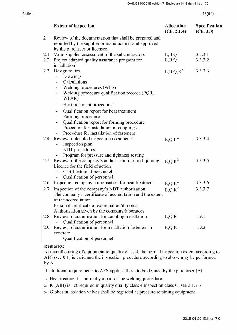
KBM 48(94)
2015-04-20, Edition 7.0
Extent of inspection Allocation (Ch. 2.1.4)
Specification (Ch. 3.3)
2 Review of the documentation that shall be prepared and reported by the supplier or manufacturer and approved by the purchaser or licensee.
2.1 Valid supplier assessment of the subcontractors E,B,Q 3.3.3.1 2.2 Project adapted quality assurance program for
installation E,B,Q 3.3.3.2
2.3 Design review - Drawings - Calculations - Welding procedures (WPS) - Welding procedure qualification records (PQR,
WPAR) - Heat treatment procedure 1 - Qualification report for heat treatment 1 - Forming procedure - Qualification report for forming procedure - Procedure for installation of couplings - Procedure for installation of fasteners
E,B,Q,K2 3.3.3.3
2.4 Review of detailed inspection documents - Inspection plan - NDT procedures - Program for pressure and tightness testing
E,Q,K2 3.3.3.4
2.5 Review of the company’s authorisation for mtl. joining Licence for the field of action - Certification of personnel - Qualification of personnel
E,Q,K2 3.3.3.5
2.6 Inspection company authorisation for heat treatment E,Q,K2 3.3.3.6 2.7 Inspection of the company’s NDT authorisation
The company’s certificate of accreditation and the extent of the accreditation Personal certificate of examination/diploma Authorisation given by the company/laboratory
E,Q,K2 3.3.3.7
2.8 Review of authorisation for coupling installation - Qualification of personnel
E,Q,K 1.9.1
2.9 Review of authorisation for installation fasteners in concrete - Qualification of personnel
E,Q,K 1.9.2
Remarks: At manufacturing of equipment to quality class 4, the normal inspection extent according to AFS (see 0.1) is valid and the inspection procedure according to above may be performed by A.
If additional requirements to AFS applies, these to be defined by the purchaser (B).
1) Heat treatment is normally a part of the welding procedure.
2) K (AIB) is not required in quality quality class 4 inspection class C, see 2.1.7.3
3) Globes in isolation valves shall be regarded as pressure retaining equipment.
ÖVS/G14/0001E edition 7 Enclosure 01 Sidan 48 av 170

KBM 49(94)
2015-04-20, Edition 7.0
3.1.2 General inspection requirements prior to manufacturing and installation IP-101
”Others”
Extent of inspection Allocation (Ch. 2.1.4)
Specification (Ch. 3.3)
1. Review of the documentation that shall be prepared and reported by the purchaser/licensee
1.1 Description and report with criteria B,Q 3.3.2.1 1.2 Design specification B,Q 3.3.2.2 1.3 Design criteria B,Q 3.3.2.2 1.4 Design loadings B,Q 3.3.3.3 1.5 Valid assessment of suppliers B,Q 3.3.2.3 1.6 Updating of flow charts B,Q 3.3.2.4 1.7 Updating classification lists / charts B,Q 3.3.2.5 2. Review of the documentation that shall be prepared
and reported by the supplier or manufacturer and approved by the purchaser or licensee
2.1 Valid supplier assessment of subcontractors T,B,Q 3.3.3.1 2.2 Project adapted quality assurance program for
installation T,B,Q 3.3.3.2
2.3 Design review - Drawings - Calculations - Welding procedures (WPS) - Heat treatment procedure2 - Qualification report for heat treatment2 - Forming procedure - Qualification report for forming procedures - Procedure for installation of couplings - Procedure for installation of fasteners
E,B,Q,A1 3.3.3.3
2.4 Review of detailed inspection documents - Inspection plan - NDT Procedures - Program for pressure and tightness testing
E,Q,A1 3.3.3.4
2.5 Review of the company’s authorisation for mtl joining Certification of line of activities Certification of personnel
E,Q,A1 3.3.3.5
2.6 Review of the company’s authorisation for heat treatment
E,Q,A1 3.3.3.6
2.7 Review of the company’s NDT authorisation - The company’s certificate of accreditation and the extent of the accreditation. - Personal certificate of examination/diploma - Authorisation given by the company/laboratory
E,Q,A1 3.3.3.7
2.8 Review of authorisation for coupling installation - Qualification of personnel
E,Q,K 1.9.1
2.9 Review of authorisation for installation fasteners in concrete - Qualification of personnel
E,Q,K 1.9.2
ÖVS/G14/0001E edition 7 Enclosure 01 Sidan 49 av 170

KBM 50(94)
2015-04-20, Edition 7.0
Remarks:
For inspection class C “E” may be rplaced with “T”
1) Extent and performance of design review and other inspection for pressure retaining equipment shall satisfy the requirements of AFS.
2) Heat treatment is normally included in the welding procedures.
ÖVS/G14/0001E edition 7 Enclosure 01 Sidan 50 av 170

KBM 51(94)
2015-04-20, Edition 7.0
3.1.3 General inspection requirements prior to manufacturing and installation IP-102
Internal parts for mechanical equipment, other than those referred in IP-100 Quality class 1-4 and 4A
Extent of inspection Allocation (Ch. 2.1.4)
Specification (Ch. 3.3)
1. Review of the documentation that shall be prepared and reported by the purchaser or licensee
1.1 Description and report with criteria B,Q 3.3.2.1 1.2 Design specification B,Q 3.3.2.2 1.3 Design criteria B,Q 3.3.2.2 1.4 Design loadings B,Q 3.3.3.3 2. Review of the documentation that shall be prepared
and reported by the supplier or manufacturer and approved by the purchaser or licensee.
2.1 Valid supplier assessment of the subcontractors T,B,Q 3.3.3.1 2.2 Project adapted quality assurance program for
installation T,B,Q 3.3.3.2
2.3 Design Review - Drawings - Calculations - Welding procedures (WPS) - Welding procedure qualification records (PQR,
WPAR) - Heat treatment procedure1 - Qualification report for heat treatment - Forming procedure - Qualification report for forming procedure
T,B,Q 3.3.3.3
2.4 Review of detailed inspection documentation - Inspection plan - NDT Procedures - Program for pressure and tightness testing
T,Q 3.3.3.4
2.5 Review of the company’s authorisation for mtl joining - Certification of line of activities or similar - Certification of personnel - Qualification of personnel
T,Q 3.3.3.5
2.6 Review of the company’s authorisation for heat treatment
T,Q 3.3.3.6
2.7 Review of the company’s NDT authorisation - The company’s certificate of accreditation and the
extent of the accreditation - Personal certificate of examination/diploma - Authorisation given by the company/laboratory
T,Q 3.3.3.7
Remarks: In general, the above requirements are valid in applicable parts, depending on type of equipment or part.
As an example when deemed appropriate well proven mechanical equipment may then be accepted with the standard testing and inspection applied by the manufacturer for respective quality class and type of equipment.
1) Heat treatment is normally a part in the welding procedure.
ÖVS/G14/0001E edition 7 Enclosure 01 Sidan 51 av 170
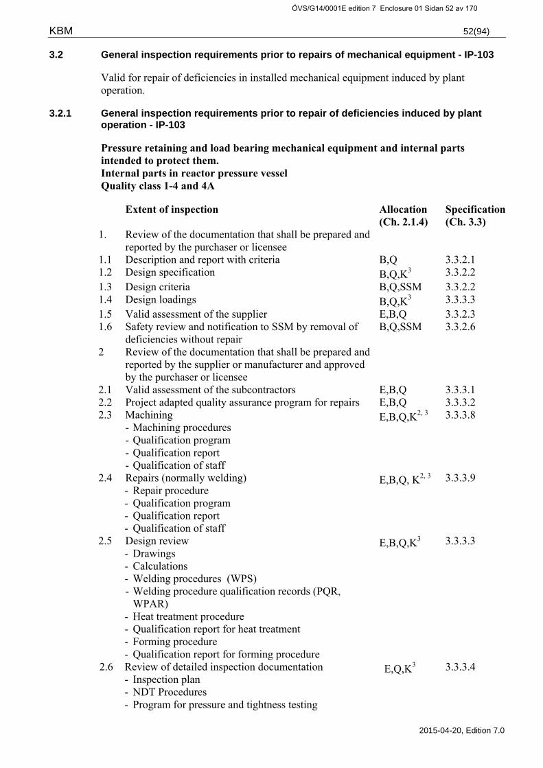
KBM 52(94)
2015-04-20, Edition 7.0
3.2 General inspection requirements prior to repairs of mechanical equipment - IP-103
Valid for repair of deficiencies in installed mechanical equipment induced by plant operation.
3.2.1 General inspection requirements prior to repair of deficiencies induced by plant operation - IP-103
Pressure retaining and load bearing mechanical equipment and internal parts intended to protect them. Internal parts in reactor pressure vessel Quality class 1-4 and 4A
Extent of inspection Allocation (Ch. 2.1.4)
Specification (Ch. 3.3)
1. Review of the documentation that shall be prepared and reported by the purchaser or licensee
1.1 Description and report with criteria B,Q 3.3.2.1 1.2 Design specification B,Q,K3 3.3.2.2 1.3 Design criteria B,Q,SSM 3.3.2.2 1.4 Design loadings B,Q,K3 3.3.3.3 1.5 Valid assessment of the supplier E,B,Q 3.3.2.3 1.6 Safety review and notification to SSM by removal of
deficiencies without repair B,Q,SSM 3.3.2.6
2 Review of the documentation that shall be prepared and reported by the supplier or manufacturer and approved by the purchaser or licensee
2.1 Valid assessment of the subcontractors E,B,Q 3.3.3.1 2.2 Project adapted quality assurance program for repairs E,B,Q 3.3.3.2 2.3 Machining
- Machining procedures - Qualification program - Qualification report - Qualification of staff
E,B,Q,K2, 3 3.3.3.8
2.4 Repairs (normally welding) - Repair procedure - Qualification program - Qualification report - Qualification of staff
E,B,Q, K2, 3 3.3.3.9
2.5 Design review - Drawings - Calculations - Welding procedures (WPS) - Welding procedure qualification records (PQR,
WPAR) - Heat treatment procedure - Qualification report for heat treatment - Forming procedure - Qualification report for forming procedure
E,B,Q,K3 3.3.3.3
2.6 Review of detailed inspection documentation - Inspection plan - NDT Procedures - Program for pressure and tightness testing
E,Q,K3 3.3.3.4
ÖVS/G14/0001E edition 7 Enclosure 01 Sidan 52 av 170

KBM 53(94)
2015-04-20, Edition 7.0
2.7 Review of the company’s welding authorisation - Certification of the line of activities - Certification of welders - Qualification of welders
E,Q,K3 3.3.3.5
2.8 Review of the company’s authorisation for heat treatment
E,Q,K3 3.3.3.6
2.9 Review of the company’s NDT authorisation - The company’s certificate of accreditation and the
extent of the accreditation - Personal certificate of examination/diploma - Authorisation given by the company/laboratory
E,Q,K3 3.3.3.7
Remarks: 1) Repair of equipment must not be initiated until probable cause of the failure is determined. 2) Qualification of repair program in quality class 1 and 2 shall be supervised and evaluated
by an Accredited Inspection Body. 3) Accredited Inspection Body participates to required extent in the cases where the failure
is of generic nature, or where it may have significance for corresponding equipment in systems of higher class.
ÖVS/G14/0001E edition 7 Enclosure 01 Sidan 53 av 170

KBM 54(94)
2015-04-20, Edition 7.0
3.3 Inspection specification – Inspection prior to manufacturing, installation or repair of installed equipment.
3.3.1 Introduction
Below describes the requirements for manufacturing, installation and repair documentation that shall be prepared and approved before the work may be started. The documentation shall be reviewed and approved by the manufacturer and the purchaser in accordance with the quality assurance program of the companies in question, and shall whenever applicable also be reviewed by an Accredited Inspection Body.
Verification of performed inspection shall be part of the final inspection documentation.
Copies of reports, authorisations, certificates and other documents mentioned below, shall be part of the final inspection documentation.
3.3.2 Documentation to be prepared by the purchaser or licensee
3.3.2.1 Description and/or report, with conditions for action to be taken
Project report, modification memorandum, general maintenance instruction or equivalent shall be prepared including a description of the work to be carried out, how this shall be done and the conditions for the work planned.
Example of contents:
Documentation needed for the evaluation of effects on the existing nuclear plant.
Clarification of effects on safety, availability and protection.
Clarification that the modification, maintenance work or repair satisfies prescribed requirements.
Clarification of prescribed requirements according to code, function and other requirements.
Clarification of classification and design specification.
Documentation serving as a basis for detailed design.
3.3.2.2 Design specifications
The design criteria, based on valid safety analysis report (SAR), shall be specified according to the principles in TBM for the respective nuclear plant. For modification work according to SSMFS 2008:13, chapter 4, 4§, a design criteria according to the principles in TBM shall be prepared.
The design specifications and included design criteria and design loadings, shall be specified by the purchaser in conjunction with purchase of replacement equipment, installation work or repair.
The design specifications included in the design criteria shall be safety reviewed and notified to SSM. The notification shall be responded by SSM prior to the Accredited Body’s issuance of certificate of compliance as per the requirements of SSMFS 2008:13.
For modifications or changes in operation conditions where the design criteria will be changed, the new valid design criteria shall be safety reviewed and notified to SSM.
ÖVS/G14/0001E edition 7 Enclosure 01 Sidan 54 av 170
KBM 55(94)
2015-04-20, Edition 7.0
For modifications where the design criteria have not been changed the valid design criteria shall be presented.
The design criteria and possible decision from SSM shall be enclosed to the documentation to be reviewed by the appointed Accredited Inspection Body. For the extent of the review of the Accredited Inspection Body, see section2.1.7.
For further details concerning design specifications and design criteria, see Technical Regulations -TBM.
3.3.2.3 Supplier assessment
Suppliers and their subcontractors shall possess and adhere to a quality assurance system that meets applicable parts of the requirements of SS-ISO 9000, or other equivalent acknowledged standard.
The licensee shall perform supplier assessment.
Further details concerning assessment of suppliers, see section 1.4.
3.3.2.4 Updating of flow charts
Flow charts, inter-locking lists and records of the set pressure for the safety valves shall be kept up-to-date.
3.3.2.5 Updating of classification lists
Classification lists shall be kept up-to-date.
3.3.2.6 Basic repair documentation
Prior to removal of cracks and other defects, which can endanger the future safety in a device, the following shall be clarified:
The necessary strength margins must be maintained and all necessary geometric conditions and surface structures can be achieved.
A probable reason for the incident shall be determined and necessary actions shall be taken to prevent the forming of new deficiencies.
The licensee shall report the results of the above calculations and analyses.
Repairs of equipment must not be started until a probable cause to the incident has been found and clarified. Qualification of method for machining and/or repairs intended for equipment belonging to any of the quality classes 1 or 2 shall be supervised and evaluated by an Accredited Inspection Body.
Work or repairs in parts of barriers and/ or mechanical equipment that is of importance for the defence-in-depth shall be safety reviewed. More in detail concerning structural integrity and repair, see Technical Regulations - TBM.
ÖVS/G14/0001E edition 7 Enclosure 01 Sidan 55 av 170

KBM 56(94)
2015-04-20, Edition 7.0
3.3.3 Documentation to be prepared by the supplier or manufacturer
3.3.3.1 Supplier assessment of sub-contractors
On the purchaser's demand, the supplier shall report the results of his assessment of sub-contractors.
3.3.3.2 Quality plan for installation and repairs of installed equipment
Works concerning equipment important for safety and operational availability must be carried out under well controlled conditions. A quality assurance program shall cover the activities. In case the manufacturer lacks an approved quality assurance program a project adapted quality plan to be prepared. The plan shall follow the guidelines of SS-ISO 10006 ”Quality management – Guidelines for quality plans” and be adapted to the particular work and the need for control so that performance and documentation is carried out in accordance with the applicable requirements.
The quality plan shall give a description of:
The manufacturer’s organisation and a plan for the performance of the work
Assessment of sub-contractors
Document control
Material control
Control and performance of inspection and testing
Co-operation and reporting to the purchaser
Documentation turn over, deviations and documentation
3.3.3.3 Design review
The design review shall assure that the documentation stated below is coherent with the design criteria stated by the purchaser, the requirements in TBM, KBM and other specifications valid for the equipment issued by the purchaser.
Drawings
The review shall comprise drawings for design, welding and adherent material specifications. The review shall verify that the documentation contains the data of importance for the pressure vessel safety, function, manufacture, inspection, installation and in-service inspection and also verify that they are correctly specified. For external purchasing of equipment, the manufacturer may due to proprietary reasons be unwilling to disclose data about e. g. fit and tolerances to other companies, this will normally be accepted.
Drawing shall to an applicable extent, comprise or refer to at least the following information:
Nuclear plant, unit, system and component number
Design pressure and design temperature and data of test pressure
Quality classification
Inspection plan
ÖVS/G14/0001E edition 7 Enclosure 01 Sidan 56 av 170

KBM 57(94)
2015-04-20, Edition 7.0
Material specification and material grade
Dimensional standard and pressure rating of parts and components
Dimensions and measurements shall be detailed to the extent required for the design calculations
Welding specification
Design loadings
In the design criteria events and combinations of events to be considered for mechanical equipment, are defined. Events including the event class unlikely event shall be considered in the design loadings.
Calculations
The review of strength calculations shall be carried out to the extent required to verify that the criteria of the design specifications and the belonging design criteria (KFM) are satisfied.
The calculation report shall contain references to design loadings, drawings, methods used for calculations and other information important for the verification of the result. The review shall verify that strength calculations have been carried out and that the results meet the specific requirements.
Manufacturing and installation procedures
Review of manufacturing and installation procedures and qualification reports shall verify the fulfilment of the requirements in TBM and KBM and other requirements stated by the purchaser.
Procedure for installation of fasteners in concrete and for installation of pipe couplings shall comprise instructions to ensure a safe and satisfactory installation.
Examples of procedures and procedure qualification reports, which to applicable extent shall be presented:
Welding procedures WPS
Welding procedure qualification report (WPAR/WPQR)
Heat treatment procedure
Heat treatment procedure qualification report
Forming procedure
Forming procedure qualification report
Procedure for installation of couplings
Procedure for installation of fasteners
Procedure for cleanliness inspection
Procedure for function inspection
ÖVS/G14/0001E edition 7 Enclosure 01 Sidan 57 av 170
KBM 58(94)
2015-04-20, Edition 7.0
3.3.3.4 Review of detailed inspection documentation
Detailed inspection plan
The review shall verify that the detailed inspection plans include the adopted inspection and testing required according to KBM.
Detailed inspection plans shall also include:
Reference to detailed drawing
Quality class
Type and extent of tests and inspections at different stages, before, during and after manufacturing, installation or repair.
Allocation of inspection assignments - "Extent/ Supervision".
Reference to the detailed inspection documentation, which the manufacturer intends to use for the inspection and testing activity.
Reference to the manufacturer’s detailed procedures for NDT.
Reference to the purchaser's inspection procedure KBM-EP in case these are used as a detailed inspection basis.
The tests and inspections the manufacturer considers needed for his full responsibility for the devise.
The added inspection, which is required when no pressure and tightness test is intended to be made.
NDT Procedures
The review shall verify that the detailed NDT procedures fulfils the requirements of applicable inspection procedure KBM-EP, and applies to all the procedures that according to the inspection procedure require preparation of procedure.
NDT procedures shall contain all necessary data for performance of the testing, evaluation and reporting of the result. The procedures shall comply with the requirements of the purchaser's inspection procedures. Requirements on the content of the NDT procedures are specified in the applicable KBM-EP inspection procedures.
For the testing with well proven and well suited methods there is normally not a requirement to prepare a detailed procedure providing that this is not stipulated by the standard in question. As an example UT of plate according to SS-EN 10160, the result reported in a test certificate as per SS-EN 10204-3.1 is in this case regarded as sufficient.
NDT procedure for testing of machined surfaces in conjunction with repairs of operational induced deficiency shall in applicable extent be qualified and evaluated according to chapter 3, 11§ in SSMFS 2008:13.
Pressure and tightness test program
The manufacturer shall in conjunction with the manufacturing prepare a program for pressure and tightness testing.
ÖVS/G14/0001E edition 7 Enclosure 01 Sidan 58 av 170

KBM 59(94)
2015-04-20, Edition 7.0
The manufacturer or, in certain cases the licensee, prepares a program for pressure and tightness test for installation or repair. Requirements of the content in the program are defined in the inspection procedure.
The program shall be reviewed and approved by the licensee according to his routines. The review shall verify compliance with the applicable inspection procedure. The review shall also verify compliance with other requirements from the licensee such as among other things the line-up for operation and isolation of the affected system or parts thereof.
3.3.3.5 Review of the company’s welding authorisation
A valid certificate of welding license or certificate, issued by an Accredited Certification Body against SS-EN 3834-2 or ASME certificate shall be presented. Authorisation for the above mentioned welding shall comprise all the welding methods, combinations of materials and geometry’s required for the welding to be performed.
The requirements are stated in 1.6.2.
Certification of welders
Copies of valid certificates for welder qualification shall be presented.
The requirements are stated in 1.6.4.
Qualification of staff
Certificates of qualification tests according to requirements in qualification program shall be presented.
The requirements are stated in 1.6.5.
3.3.3.6 Review of the company’s heat treatment authorisation
Heat treatment of welding shall be part of the welding procedure qualification according to 1.6.3.
Other requirements for heat treatment are stated in 1.7.
3.3.3.7 Review of the company’s NDT authorisation
The following records shall be available for review during the testing and also be included in the final inspection records:
The company’s certificate of accreditation and the extent of the accreditation.
Personal certificate of examination or diploma
Authorisation given by the company/laboratory
The requirements are stated in 1.8.
ÖVS/G14/0001E edition 7 Enclosure 01 Sidan 59 av 170

KBM 60(94)
2015-04-20, Edition 7.0
3.3.3.8 Review of documentation for removal of service induced deficiencies
Service induced deficiencies in installed equipment may be removed without repair of the material or weld material if, at least, below defined documents are safety reviewed and approved by the licensee and reviewed by an Accredited Inspection Body:
Machining procedure
Qualification program for machining procedure
Qualification report
Qualification of method for machining intended for use in equipment belonging to quality class 1 or 2 shall be supervised and assessed by an Accredited Inspection Body.
In addition to the above mentioned machining documents cause of defect analysis, design specifications, design criteria, design loadings and strength analysis shall be prepared to the extent required for the intended measure. This type of measure is by SSM considered to be a nuclear plant modification and shall be reviewed by an Accredited Inspection Body to the extent specified in 2.1.7.2.
3.3.3.9 Review of documentation for repair of service induced deficiencies, normally welding
Repairs of installed equipment shall be carried out according to repair program qualified for the specific purpose, which can restore the required properties by safe margin for the equipment to meet the basic requirements for proper use.
Work or repairs in parts of barriers or mechanical equipment that is of importance for the defence-in-depth shall be safety reviewed. More in detail concerning durabilty and repairs, see Technical Regulations - TBM.
Qualification of a method for machining and repair intended for equipment belonging to either of the quality classes 1 or 2, shall be supervised and evaluated by an Accredited Inspection Body.
The manufacturer shall supply the licensee/purchaser with detailed repair documentation for review and approval as stated below:
Repair procedure
Qualification program for the repair
Qualification report
Qualification of staff and equipment
In detail, when documentation according to the above is required see Technical Regulations - TBM.
ÖVS/G14/0001E edition 7 Enclosure 01 Sidan 60 av 170

KBM 61(94)
2015-04-20, Edition 7.0
4 MANUFACTURE INSPECTION
4.1 General requirements for material inspection IP-200
1. Pressure retaining equipment or parts of equipment IP-201 to 209
2. Load bearing equipment or parts of equipment IP-221 to 222
3. Internal parts in mechanical equipment IP-230
4. Internal parts in reactor pressure vessels and Steam Generators IP-240
4.2 General inspection requirements – Manufacturing/assembling IP-300
1. Mechanical equipment or parts thereof IP-300
4.3 General inspection requirements – Finished mechanical equipment or parts thereof IP-400
1. Finished mechanical equipment or parts thereof IP-400
NOTE ! The general inspection requirements “IP” and inspection procedures “EP” must be read together. The detailed quality control documentation shall be adopted for each individual design case. The required testing, inspection and extent thereof and acceptance criteria is to be judged for each individual case.
ÖVS/G14/0001E edition 7 Enclosure 01 Sidan 61 av 170
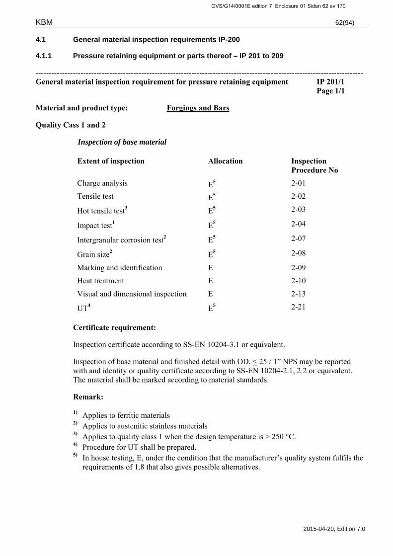
KBM 62(94)
2015-04-20, Edition 7.0
4.1 General material inspection requirements IP-200
4.1.1 Pressure retaining equipment or parts thereof – IP 201 to 209
---------------------------------------------------------------------------------------------------------------------------- General material inspection requirement for pressure retaining equipment IP 201/1
Page 1/1
Material and product type: Forgings and Bars
Quality Cass 1 and 2
Inspection of base material
Extent of inspection Allocation Inspection Procedure No
Charge analysis E5 2-01
Tensile test E5 2-02
Hot tensile test3 E5 2-03
Impact test1 E5 2-04
Intergranular corrosion test2 E5 2-07
Grain size2 E5 2-08
Marking and identification E 2-09
Heat treatment E 2-10
Visual and dimensional inspection E 2-13
UT4 E5 2-21
Certificate requirement:
Inspection certificate according to SS-EN 10204-3.1 or equivalent.
Inspection of base material and finished detail with OD. < 25 / 1” NPS may be reported with and identity or quality certificate according to SS-EN 10204-2.1, 2.2 or equivalent. The material shall be marked according to material standards.
Remark:
1) Applies to ferritic materials 2) Applies to austenitic stainless materials 3) Applies to quality class 1 when the design temperature is > 250 °C. 4) Procedure for UT shall be prepared. 5) In house testing, E, under the condition that the manufacturer’s quality system fulfils the
requirements of 1.8 that also gives possible alternatives.
ÖVS/G14/0001E edition 7 Enclosure 01 Sidan 62 av 170

KBM 63(94)
2015-04-20, Edition 7.0
General material inspection requirements for pressure retaining equipment IP 201/3 Page 1/1
Material and product type: Forgings and Bars
Quality Class 3, 4 and 4A
Inspection of base material
Extent of inspection Allocation Inspection Procedure No
Charge analysis E4 2-01 Tensile test E4 2-02
Impact test1 E4 2-04
Intergranular corrosion test2 E4 2-07
Grain size2 E4 2-08
Marking and identification E 2-09 Heat treatment E 2-10 Visual and dimensional inspection E 2-13 UT3 E4 2-21
Certificate requirement:
Inspection certificate according to SS-EN 10204-3.1 or equivalent.
Inspection of base material and finished detail with OD < 25 / 1”NPS may be reported with an identity or quality certificate according to SS-EN 10204-2.1, 2.2 or equivalent. The material shall be marked according to material standard.
Materials for equipment in quality class 4 that cannot cause discharge of radioactive substance and “other” systems shall at least be documented and marked in the extent and according to the requirements stated by AFS.
Remark:
1) Applies to ferritic materials. 2) Applies to austenitic stainless materials. 3) If required according to the EP-inspection procedure, a procedure description for UT
shall be prepared. 4) In house testing, E, under the condition that the manufacturer’s quality system fulfils the
requirements of 1.8 that also gives possible alternatives.
ÖVS/G14/0001E edition 7 Enclosure 01 Sidan 63 av 170

KBM 64(94)
2015-04-20, Edition 7.0
General material inspection requirements for pressure retaining equipment IP 202/1 Page 1/1
Material and product type: Castings
Quality Class 1 and 2
Inspection of base material
Extent of inspection Allocation Inspection Procedure No
Charge analysis E4 2-01 Tensile test E4 2-02
Hot tensile test1 E4 2-03
Impact test2 E4 2-04 Marking and identification E 2-09 Heat treatment E 2-10 Visual and dimensional inspection E 2-13 RT3 E4 2-27
Certificate requirement:
Inspection certificate according toSS-EN 10204-3.1 or equivalent.
Remarks:
1) Applies to quality class 1 when the design temperature is > 250° C. 2) Applies to ferritic materials. 3) Extent as in ASME III, see Inspection Procedure. 4) In house testing, E, under the condition that the manufacturer’s quality system fulfils the
requirements of 1.8 that also gives possible alternatives.
ÖVS/G14/0001E edition 7 Enclosure 01 Sidan 64 av 170

KBM 65(94)
2015-04-20, Edition 7.0
General material inspection requirements for pressure retaining equipment IP 202/3 Page 1/1
Material and product type: Castings
Quality Class 3, 4 and 4A
Inspection of base material
Extent of inspection Allocation Inspection Procedure No
Charge analysis E3 2-01 Tensile test E3 2-02
Impact test1 E3 2-04 Marking and identification E 2-09 Heat treatment E 2-10 Visual and dimensional inspection E 2-13 RT2 E3 2-27
Certificate requirement:
Inspection certificate according to SS-EN 10204-3.1 or equivalent.
Materials for equipment in quality class 4 that cannot cause discharge of radioactive substance and “other” systems shall at least be documented and marked in the extent and according to the requirements stated by AFS.
Remarks:
1) Applies to ferritic materials. 2) Extent depending on the material usage factor, see Inspection Procedure. 3) In house testing, E, under the condition that the manufacturer’s quality system fulfils the
requirements of 1.8 that also gives possible alternatives.
ÖVS/G14/0001E edition 7 Enclosure 01 Sidan 65 av 170

KBM 66(94)
2015-04-20, Edition 7.0
General material inspection requirements for pressure retaining equipment IP 203/1 Page 1/1
Material and product type: Plate
Quality Class 1 and 2
Inspection of base material
Extent of inspection Allocation Inspection Procedure No
Charge analysis E5 2-01 Tensile test E5 2-02
Hot tensile test1 E5 2-03
Impact test2 E5 2-04
Intergranular corrosion test3 E5 2-07
Grain size3 E5 2-08
Marking and identification E 2-09 Heat treatment E 2-10 Visual and dimensional inspection E 2-13 UT4 E5 2-20
Certificate requirement:
Inspection certificate according to SS-EN 10204-3.1 or equivalent.
Remarks:
1) Applies to quality class 1 when the design temperature is > 250° C. 2) Applies to ferritic materials. 3) Applies to austenitic stainless materials. 4) Applies to plate with a thickness > 6 mm. See Inspection Procedure for further
information. 5) In house testing, E, under the condition that the manufacturer’s quality system fulfils the
requirements of 1.8 that also gives possible alternatives.
ÖVS/G14/0001E edition 7 Enclosure 01 Sidan 66 av 170

KBM 67(94)
2015-04-20, Edition 7.0
General material inspection requirements for pressure retaining equipment IP 203/3 Page 1/1
Material and product type: Plate
Quality Class 3, 4 and 4A
Inspection of base material
Extent of inspection Allocation Inspection Procedure No
Charge analysis E4 2-01 Tensile test E4 2-02
Impact test1 E4 2-04
Intergranular corrosion test2 E4 2-07
Grain size3 E4 2-08
Marking and identification E 2-09 Heat treatment E 2-10 Visual and dimensional inspection E 2-13 UT3 E4 2-20
Certificate requirement:
Inspection certificate according to SS-EN 10204-3.1 or equivalent.
Materials for equipment in quality class 4 that cannot cause discharge of radioactive substance and “other” systems shall at least be documented and marked in the extent and according to the requirements stated by AFS.
Remarks:
1) Applies to ferritic materials. 2) Applies to austenitic stainless materials. 3) Applies to plate with a thickness > 6 mm. See Inspection Procedure for further data. 4) In house testing, E, under the condition that the manufacturer’s quality system fulfils the
requirements of 1.8 that also gives possible alternatives.
ÖVS/G14/0001E edition 7 Enclosure 01 Sidan 67 av 170

KBM 68(94)
2015-04-20, Edition 7.0
General material inspection requirements for Pressure retaining equipment IP 204/1 Page 1/1
Material and product type: Pipes and fittings
Quality Class 1 and 2
Inspection of base material
Extent of inspection Allocation Inspection Procedure No
Charge analysis E6 2-01
Tensile test E6 2-02
Hot tensile test1 E6 2-03
Impact test2 E6 2-04
Other technological testing E6 2-06
Intergranular corrosion test4 E 2-07
Grain size4 E6 2-08
Marking and identification E 2/4-09
Heat treatment E 2-10
Visual and dimensional inspection E 2/4-13
Pressure testing3 E6 2-14
PT or MT of final surface E6 4-16/17
ET/UT5 E6 2-19/22
Welded pipes and welded pipe fittings shall also be inspected as per IP-301 and IP-401.
Certificate requirement:
Inspection certificate according to SS-EN 10204-3.1 or equivalent.
Remarks:
1) Applies to quality class 1 when the design temperature is > 250 °C. 2) Applies to ferritic materials. 3) Pressure testing may be replaced with ET or UT according to applicable material
standards or technical delivery conditions. 4) Applies to austenitic stainless materials. 5) Procedure shall be drawn up when required in the actual EP instruction. 6) In house testing, E, under the condition that the manufacturer’s quality system fulfils the
requirements of 1.8 that also gives possible alternatives.
ÖVS/G14/0001E edition 7 Enclosure 01 Sidan 68 av 170

KBM 69(94)
2015-04-20, Edition 7.0
General material inspection requirements for pressure retaining equipment IP 204/3 Page 1/1
Material and product type: Pipes and fittings
Quality Class 3, 4 and 4A
Inspection of base material
Extent of inspection Allocation Inspection Procedure No
Charge analysis E5 2-01 Tensile test E5 2-02
Impact test1 E5 2-04 Other technological testing E5 2-06
Intergranular corrosion test3 E 2-07
Grain size3 E5 2-08 Marking and identification E 2/4-09 Heat treatment E 2-10 Visual and dimensional inspection E 2/4-13 Pressure testing2 E5 2-14 PT or MT of final surface E5 4-16/17
ET/UT4 E5 2-19/22
Welded pipes and welded pipe fittings shall also be inspected as per IP-301 and IP-401. In quality class 4 pipes and fittings manufactured as per SS-EN 10217-7 respectively SS-EN 10253-2, -4 are accepted.
Certificate requirement:
Inspection certificate according to SS-EN 10204-3.1 or equivalent.
Materials for equipment in quality class 4 that cannot cause discharge of radioactive substance and “other” systems shall at least be documented and marked in the extent and according to the requirements stated by AFS.
Remarks:
1) Applies to ferritic materials. 2) Pressure testing may be replaced with ET or UT according to applicable material
standards or technical delivery conditions. 3) Applies to austenitic stainless materials. 4) Procedure shall be drawn up when required in the actual EP instruction. 5) In house testing, E, under the condition that the manufacturer’s quality system fulfils the
requirements of 1.8 that also gives possible alternatives.
ÖVS/G14/0001E edition 7 Enclosure 01 Sidan 69 av 170

KBM 70(94)
2015-04-20, Edition 7.0
General material inspection requirements for pressure retaining equipment IP 205 Page 1/1
Material and product type: Heat exchanger tubes
Quality Class 2, 3, 4 and 4A
Inspection of base material
Extent of inspection Allocation Inspection Procedure No
Charge analysis E5 2-01
Tensile test E5 2-02
Impact test1 E5 2-04
Other technological testing E5 2-06
Intergranular corrosion test3 E 2-07
Marking and identification E 2/4-09
Heat treatment E 2-10
Visual and dimensional inspection E 2/4-13
Pressure testing2 E5 2-14
PT or MT of final surface E5 2-16/17
ET/UT4 E5 2/4-19/22
Cold bending of HEX tubes Qualification report
E, B 286
Certificate requirement:
Inspection certificate according toSS-EN 10204-3.1 or equivalent.
Material for equipment in quality class 4 and “Others” shall be documented and marked at least to the extent and the requirements stated in AFS.
Remarks:
1) Applies to ferritic materials. 2) Pressure testing may be replaced with ET or UT according to applicable material
standards or technical delivery conditions. 3) Applies to austenitic stainless materials. 4) Procedure shall be prepared, for extent and technique, see the Inspection Procedure. 5) In house testing, E, under the condition that the manufacturer’s quality system fulfils the
requirements of 1.8 that also gives possible alternatives.
ÖVS/G14/0001E edition 7 Enclosure 01 Sidan 70 av 170

KBM 71(94)
2015-04-20, Edition 7.0
General material inspection requirements for pressure retaining equipment IP 206/1 Page 1/1
Material and product type: Bolts and Nuts
Quality Class 1 and 2
Inspection of base material for bolts and nuts, "Special"
Extent of inspection Allocation Inspection Procedure No
Charge analysis E4 2-01
Tensile test E4 2-02
Hot tensile test1 E4 2-03
Impact test2 E4 2-04
Hardness testing E4 2-05
Marking and identification E 2/4-09
Heat treatment E 2-10
Visual and dimensional inspection E 2/4-13
PT or MT of final surface E4 2-16/17
UT of material to > M 24 / 1” 3 E4 2-21
Certificate requirement:
Inspection certificate according to SS-EN 10204-3.1 or equivalent.
ÖVS/G14/0001E edition 7 Enclosure 01 Sidan 71 av 170

KBM 72(94)
2015-04-20, Edition 7.0
2. Inspection of base material and finished bolts and nuts, “Standard”
Testing, inspection and marking shall be carried out and documented in accordance with the material standard chosen or the specification of material including the technical delivery and inspection requirements.
Requirements in addition to standard:
Surface crack indication PT/MT > M24 / 1” E4 2/4-16/17
Marking and identification E 2/4-09
Certificate requirement:
Identity certificate according to SS-EN 10204-2.1 or equivalent.
For carbon steel bolts and nuts marked with the manufacturer’s name and strength class no certificate will be required.
For stainless material marked with the manufacturer’s name, strength class and the material designation e.g. A2, A4 and 660, no certificate will be required.
Remarks:
1) Applies to quality class 1 when the design temperature is > 250 °C. 2) Applies to ferritic materials. 3) Procedure shall be prepared for UT. 4) In house testing, E, under the condition that the manufacturer’s quality system fulfils the
requirements of 1.8 that also gives possible alternatives.
ÖVS/G14/0001E edition 7 Enclosure 01 Sidan 72 av 170

KBM 73(94)
2015-04-20, Edition 7.0
General material inspection requirements for pressure retaining equipment IP 206/3 Page 1/1
Material and product type: Bolts and nuts
Quality Class 3, 4 and 4A
Inspection of base material and finished bolts and nuts, "Special"
Extent of inspection Allocation Inspection Procedure No
Charge analysis E2 2-01
Tensile test E2 2-02
Impact test E2 2-04
Hardness testing E2 2-05
Marking /identification E 2-09
Heat treatment E 2-10
Visual and dimensional inspection E 2-13
PT or MT of final surface E2 2-16/17
UT of material till > M 24 / 1” 1 E2 2-21
Certificate requirement:
Inspection certificate according to SS-EN 10204-3.1 or equivalent
2. Inspection of base material and finished bolts and nuts, "Standard"
Testing, inspection and marking shall be carried out and documented in accordance with the material standard chosen or the specification of material including the technical delivery and inspection requirements.
Marking and identification E 2-00
Certificate requirement:
Identity certificate according to SS-EN 10204-2.1 or equivalent.
For carbon steel bolts and nuts marked with the manufacturer’s name and strength class no certificate will be required.
For stainless material marked with the manufacturer’s name, strength class and the material designation e.g. A2, A4 and 660, no certificate will be required.
Remarks:
1) Procedure shall be prepared for UT. 2) In house testing, E, under the condition that the manufacturer’s quality system fulfils the
requirements of section 1.8 that also gives possible alternatives.
ÖVS/G14/0001E edition 7 Enclosure 01 Sidan 73 av 170

KBM 74(94)
2015-04-20, Edition 7.0
General material inspection requirements for pressure retaining equipment IP 207 Page 1/1
Material and product type: Bellows for valves
Quality Class 1-4 and 4A
Inspection of base material for bellow element to valve
Extent of inspection Allocation Inspection Procedure No
Charge analysis E2 2-01
Intergranular corrosion test1 E2 2-07 Marking/ identification E 2-09 Visual and dimensional inspection E 2-13
Certificate requirement:
Inspection certificate according to SS-EN 10204-3.1.
Welds for valve bellows can be accepted without detailed welding documentation as per IP-100.
Material for equipment in quality class 4 and “Others” shall be documented and marked at least to the extent and the requirements stated in AFS.
Remarks:
1) Applies to austenitic stainless materials. 2) In house testing, E, under the condition that the manufacturer’s quality system fulfils the
requirements of section 1.8 that also gives possible alternatives.
ÖVS/G14/0001E edition 7 Enclosure 01 Sidan 74 av 170

KBM 75(94)
2015-04-20, Edition 7.0
General material inspection requirements for pressure retaining equipment IP 208 Page 1/1
Material and product type: Bellows for pressure vessels and pipes
Quality Class 2-4 and 4A
Inspection of base material and finished bellow element – pressure vessel and pipes
Extent of inspection Allocation Inspection Procedure No
Charge analysis E2 2-01 Tensile test E2 2-02
Intergranular corrosion test1 E2 2-07
Grain size1 E2 2-08 Marking and identification E 2/4-09 Heat treatment E 2-10 Visual and dimensional inspection E 2/4-13
Certificate requirement:
Inspection certificate according to SS-EN 10204-3.1 or equivalent.
Material identity certificate according to SS-EN 10204-2.1 or equivalent may normally be accepted for rubber bellow element.
Material for equipment in quality class 4 and “Others” shall be documented and marked at least to the extent and the requirements stated in AFS.
Remarks:
1) Applies to austenitic stainless materials. 2) In house testing, E, under the condition that the manufacturer’s quality system fulfils the
requirements of 1.8 that also gives possible alternatives.
ÖVS/G14/0001E edition 7 Enclosure 01 Sidan 75 av 170

KBM 76(94)
2015-04-20, Edition 7.0
General material inspection requirements for pressure retaining equipment IP 209 Page 1/1
Material and product type: Valves closing devices
Quality Class 1-4 and 4A
Guidelines for inspection of base material for valve closing devices
Extent of inspection Allocation Inspection Procedure No
Charge analysis E1 2-01 Marking and identification E 2/4-09 Visual and dimensional inspection E 2/4-13 Inspection of material and shapes shall generally be performed and reported according to the extent specified in the applicable material standard and the belonging technical delivery and inspection conditions.
Certificate requirement:
Inspection certificate according to SS-EN 10204-3.1 or equivalent. Material identity certificate according to SS-EN 10204-2.1 or equivalent, can normally be accepted for small bore valves DN< 50 (< 2” NPS) in quality class 1 and 2 and for valves in quality class 3 and 4.
Material for equipment in quality class 4 and “Others” shall be documented and marked at least to the extent and the requirements stated in AFS.
Remarks:
1) In house testing, E, under the condition that the manufacturer’s quality system fulfils the requirements of 1.8 that also gives possible alternatives.
ÖVS/G14/0001E edition 7 Enclosure 01 Sidan 76 av 170

KBM 77(94)
2015-04-20, Edition 7.0
4.1.2 Load bearing equipment and equipment parts – IP 221 to 222
----------------------------------------------------------------------------------------------------------------------------
General material control requirements for load bearing parts IP 221 Page 1/1
Material and product type: Material for load bearing equipment incl. pipe rupture restrains
Quality Class 1-4 and 4A (pipe rupture restrains are always quality class 3)
Inspection of base material for load bearing equipment
Extent of inspection Allocation Inspection Procedure No
Marking and identification as in approved material standard1
E 2-00/09
UT2 E4 2-20/2-21
Certificate requirement:
Identity certificate according toS S-EN 10204-2.1 or equivalent.
Material for equipment in quality class 4 and “Others” shall be documented and marked at least to the extent and the requirements stated in AFS.
Inspection of other load bearing equipment or equipment details
Test requirements Extent/ Supervision Inspection Procedure No
Marking and identification as in approved material standard3
E 2-00/09
Remarks:
1) Material identity and quality certificate can in certain cases be replaced by marking of the material with manufacturer and material quality. The manufacturer shall make this marking.
2) The requirement applies for details transmitting lateral loads where the thickness of the material is > 6 mm. Procedure for UT shall be drawn up, extent and technique see the inspection procedure.
3) The material for anchoring elements such as spring assemblies, constant load hangers and snubbers for dynamic loads, shall be inspected and tested to the extent stated in the manufacturer's approved product specifications for the element in question. The documentation shall be reviewed by the purchaser and whenever required, also by Accredited Inspection Body (see IP-100).
4) In house testing, E, under the condition that the manufacturer’s quality system fulfils the requirements of 1.8 that also gives possible alternatives.
ÖVS/G14/0001E edition 7 Enclosure 01 Sidan 77 av 170

KBM 78(94)
2015-04-20, Edition 7.0
General material control requirements for load bearing parts IP 222 Page 1/1
Material and product type: Material for fasteners in concrete
Quality Class 1-4 and 4A
Inspection of base material for fasteners in concrete
Extent of inspection Allocation Inspection Procedure No
Charge analysis1 E3 2-01 Inspection of marking and identification1
E 2/4-09
UT of forgings and bars2 E3 2-21
Certificate requirement:
Inspection certificate according to SS-EN 10204-3.1
Material for equipment in quality class 4 and “Others” shall be documented and marked at least to the extent and the requirements stated in AFS. .
Remarks:
1) For expanding fasteners, which are type approved by the National Swedish Board of Buildings / SITAC (Swedish Institute for Technical approval in construction, Svenskt Byggodkännande AB) or corresponding body e.g. within European Organisation for Technical Approvals (EOTA), the material testing prescribed in the type approval certificate will be accepted.
2) UT shall be carried out when the material in grouting bolts, expander bolts etc is a design factor for the grouting element. The UT requirement applies when OD. > 25 mm / 1”.
3) In house testing, E, under the condition that the manufacturer’s quality system fulfils the requirements of 1.8 that also gives possible alternatives.
ÖVS/G14/0001E edition 7 Enclosure 01 Sidan 78 av 170

KBM 79(94)
2015-04-20, Edition 7.0
4.1.3 Internal parts in mechanical equipment – IP 230
----------------------------------------------------------------------------------------------------------------------------
General material inspection requirement for internal parts IP 230 Page 1/1
Material and product type: Internal parts in mechanical equipment according to IP 102
Quality Class 1-4 and 4A
Inspection of base material
Extent of inspection Allocation Inspection Procedure No
Material testing and inspection as per method and extent suggested by the manufacturer 1
T Manufacturer’s requirement
Certificate requirement:
Inspection certificate according to SS-EN 10204-3.1 for “piece production” and identity certification according to SS-EN 10204-2.1 or equivalent for series produced equipment.
Remarks:
1) The material standard and tests and inspections included in this standard, as suggested by the manufacturer, shall be documented for “piece production”. The documentation shall also comprise all the tests and inspections the manufacturer considers necessary for taking full responsibility. The documentation shall be reviewed and approved by the purchaser, together with all other basic documentation for manufacturing.
ÖVS/G14/0001E edition 7 Enclosure 01 Sidan 79 av 170

KBM 80(94)
2015-04-20, Edition 7.0
4.1.4 Internals in reactor pressure vessels and Steam Generators – IP 240
----------------------------------------------------------------------------------------------------------------------------
General material inspection requirements for above internals IP 240 Page 1/1
Material and product type: Material for internals according to IP 100
Quality Class 1-4
Guidelines for inspection of base material
Extent of inspection Allocation Inspection Procedure No
Charge analysis E4 2-01 Tensile test E4 2-02 Hot tensile test E4 2-03
Impact test1 E4 2-04
Intergranular corrosion test2 E4 2-07
Grain size2 E4 2-08
Marking and identification E 2-09 Heat treatment E 2-10 Visual and dimensional inspection E 2-13 UT E4 2-20
UT3 E4 2-21
Certificate requirement:
Inspection certificate according to SS-EN 10204-3.1 or equivalent.
Inspection of base material and finished detail with OD < 25 / 1” may be reported with an identity or quality certificate as in SS-EN 10204-2.1 or equivalent. The material shall be marked according to material standard.
Remarks:
1) Applies to ferritic materials. 2) Applies to austenitic stainless materials. 3) Procedure shall be prepared for UT. 4) In house testing, E, under the condition that the manufacturer’s quality system fulfils
the requirements of 1.8 that also gives possible alternatives
ÖVS/G14/0001E edition 7 Enclosure 01 Sidan 80 av 170

KBM 81(94)
2015-04-20, Edition 7.0
4.2 General inspection requirements – Manufacture/Joining – IP 300
4.2.1 Mechanical equipment and parts thereof – IP 300
----------------------------------------------------------------------------------------------------------------------------
General inspection requirements for manufacturing IP 301/1 Page 1/2
Mechanical equipment and parts thereof
Quality Class 1-3, and 4 inspection class A-B as well as 4A
Prescribed testing and inspection at welding
Extent of Inspection Insp. proc.
Butt weld
Fillet weld
Corner weld
T- joint weld
Sur- facingweld
Weld Butter ing
Seal weld
Welds valves bellow elem.
Welds valve closing device
Inspection of heat treatment 3-10 E E E E E E E E T
Test of weld filler metal 3-11 E E E E E E E E E
Inspection of welding9 3-12 E E E E E E E E T
Visual & Dimensional Insp. 9 3-13 E E E E E E E E E
PT or MT of weld 7 3-16
3-17
L L L L L L L L L
UT of surfacing weld 2, 4, 7 3-23 L T
UT of welded joint 1, 4, 7 3-24 L L L L
RT of welded joint 1, 4, 7 3-28 L L L
Review of radiographs 7 3-28 L L L
Inspection of weld repair 3 376
Other testing and inspection T T T T T T T T T T
Other inspections in conjunction with manufacturing
Extent of inspection Allocation Inspection Procedure No
Inspection of pipe bending8 E 3-,5-43
Inspection of installation of couplings8 E 3-,5-48
ÖVS/G14/0001E edition 7 Enclosure 01 Sidan 81 av 170

KBM 82(94)
2015-04-20, Edition 7.0
General inspection requirements for manufacture IP 301/1 Page 2/2
Mechanical equipment and parts thereof
Quality Class 1-3, and 4 inspection class A-B along with 4A
Remarks:
1) For weld in ferrite steel with a thickness of the material > 8 mm, UT is applicable according to inspection procedure 3-24 or RT according to inspection procedure 3-28. For other welds RT according to inspection procedure 3-28. For UT of longitudinally welded tubes testing and requirements according to inspection procedure 2-22 are applicable regardless of the thickness of the material.
2) Low alloy steel, which is not documented resistant to re-heating cracks, shall be further tested for cracks in cladding material and heat affected zone (see inspection procedure 2-23).
3) The original extent of inspection and supervision of inspection is valid. 4) Does not apply to welded joints in valves and armatures with DN 25 /1” NPS.
Note! The excemption does not apply to radiographic examination EP 3-28 of pressure retaining butt welds in equipment.
7) The authorisation for testing is described in 1.8. 8) The inspection shall be performed according to approved procedure. 9) The supervision by the Inspection Body at welding is performed by the routines of the
accredited Inspection Body.
ÖVS/G14/0001E edition 7 Enclosure 01 Sidan 82 av 170

KBM 83(94)
2015-04-20, Edition 7.0
General inspection requirements for manufacture IP 301/4 Page 1/2
Mechanical equipment or parts thereof
Quality Class 4 inspection class C
Prescribed testing and inspection at welding
Extent of Inspection Insp. proc.
Butt weld
Fillet weld
Corner weld
T- joint weld
Sur- facingweld
Weld Butter ing
Seal weld
Welds valves bellow elem.
Welds valve closing device
Inspection of heat treatment 3-10 T T T T T T Test of weld filler metal 3-11 T T T T T T Inspection of welding 3-12 T T T T T T
Visual and Dimensional Inspection
3-13 T T T T T T T
PT or MT of weld 2 3-16 3-17
L L L L L L L
UT of surfacing weld 3-23 T
UT of welded joint 1, 2 3-24 L L L L
RT of welded joint 1, 2 3-28 L L L
Review of radiographs 3-28 L L L
Inspection of weld repair 3 376
Other testing and inspection T T T T T T T T T
Other inspections in conjunction with manufacturing
Extent of inspection Allocation Inspection Procedure No
Inspection of pipe bending4 T 3-,5-43
Inspection of installation of couplings4 T 3-,5-48
ÖVS/G14/0001E edition 7 Enclosure 01 Sidan 83 av 170

KBM 84(94)
2015-04-20, Edition 7.0
General inspection requirements for manufacture IP 301/4 Page 2/2
Mechanical equipment or parts thereof
Quality Class 4 inspection class C
Remarks:
1) For weld in ferritic steel with a thickness of the material > 8 mm, UT is applicable according to inspection procedure 3-24 or RT according to inspection procedure 3-28. For other welds, RT according to inspection procedure 3-28.
2) NDTof weld joints in inspection class C is normally not required. 3) The original extent of supervision for inspection is valid. 4) The inspection shall be performed in accordance with approved procedure.
ÖVS/G14/0001E edition 7 Enclosure 01 Sidan 84 av 170

KBM 85(94)
2015-04-20, Edition 7.0
4.3 General inspection requirements – Finished mechanical equipment or subassembly IP 400
4.3.1 Finished mechanical equipment or subasembly – IP 400
----------------------------------------------------------------------------------------------------------------------------
General inspection requirements for finished equipment IP 401 Page 1/1
Pipes, pipe parts and tubes
Quality Class 1-4 and 4A
Extent of inspection Allocation Inspection Procedure No
Marking and identification E,Q 4-09 Visual and dimensional inspection E,Q 4-13 Pressure and tightness testing1 E,Q 4-14 PT or MT, of final surface L5 4-16/17
Final inspection3 K 4 Inspection of cleanliness T 425 Inspection of packing T 435
Quality Control Documentation
Review of final quality control documentation2
E,Q,K 190
Remarks:
1) May be performed at the manufacturer or licensee's workshop with the approval of the purchaser.
2) A review of the quality control documentation may normally be performed as a receipt inspection at the purchaser/licensee. The inspection can also, be carried out as final inspection at the supplier’s shop, if the purchaser deems this necessary or practical. K is not required in quality class 4 inspection class C.
3) Is not required in quality class 4 inspection class C. 4) According to the Accredited Inspection Body routines. 5) See section 1.8.
ÖVS/G14/0001E edition 7 Enclosure 01 Sidan 85 av 170

KBM 86(94)
2015-04-20, Edition 7.0
General inspection requirements for finished equipment IP 402 Page 1/1
Valves and other ancillaries
Quality Class 1-4 and 4A
Extent of inspection Allocation Inspection Procedure No
Marking and identification E,Q 4-09 Visual and dimensional inspection E,Q 4-13 Pressure and tightness testing E,Q 4-14 PT or MT of final surface L4 4-16/17
Final inspection2 K 3 Inspection of tightness over closing device T 441-444 Function test T 451-453 Inspection of cleanliness T 425 Inspection of corrosion protection T 430 Inspection of packaging T 435
Quality Control Documentation
Review of final quality control documentation1
E,Q,K 190
Remarks:
1) Inspection of the equipment and review of quality control documentation can normally be carried out as final inspection at the purchaser or licensee. The inspection can also, be carried out as final inspection at the supplier's shop, if the purchaser deems this necessary or practical. K is not required in quality class 4 inspection class C.
2) Is not required in quality class 4 inspection class C. 3) According to the Accredited Inspection Body routines. 4) See section 1.8.
ÖVS/G14/0001E edition 7 Enclosure 01 Sidan 86 av 170
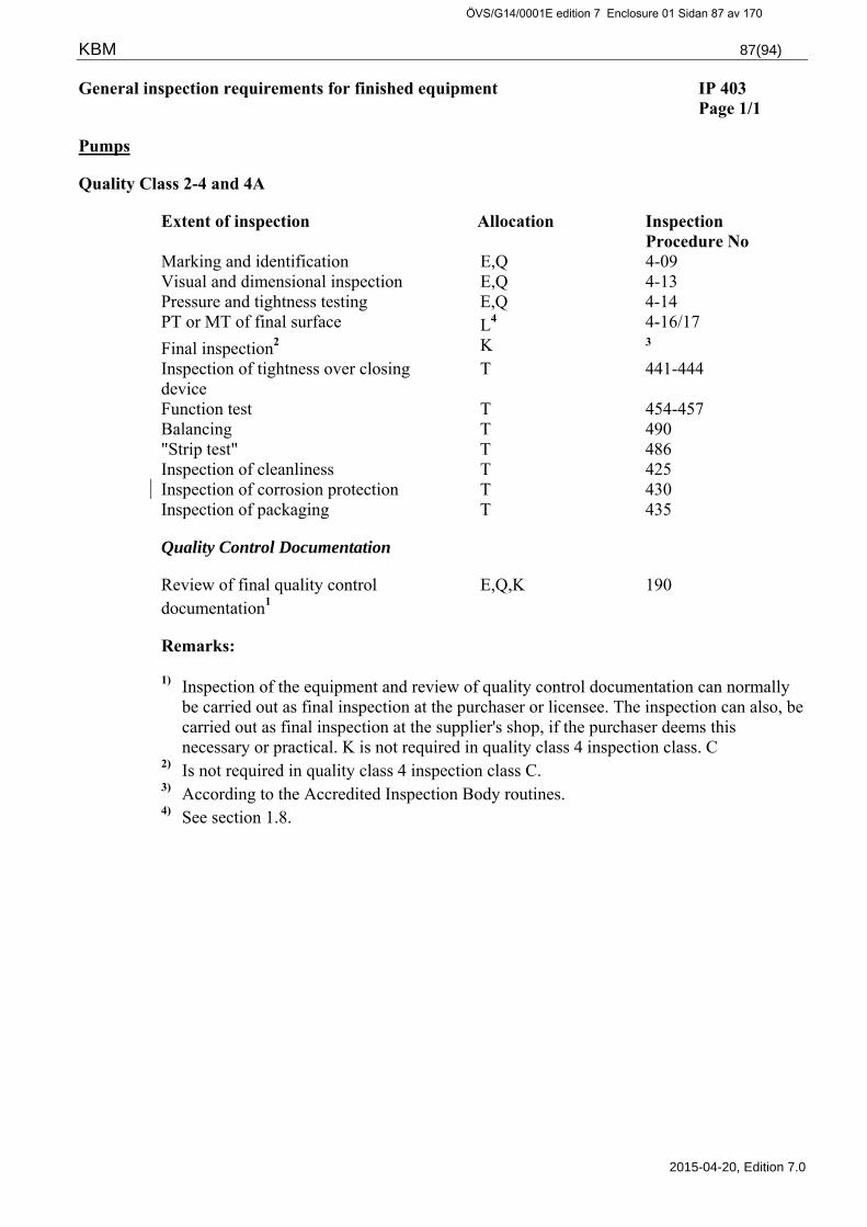
KBM 87(94)
2015-04-20, Edition 7.0
General inspection requirements for finished equipment IP 403 Page 1/1
Pumps
Quality Class 2-4 and 4A
Extent of inspection Allocation Inspection Procedure No
Marking and identification E,Q 4-09 Visual and dimensional inspection E,Q 4-13 Pressure and tightness testing E,Q 4-14 PT or MT of final surface L4 4-16/17
Final inspection2 K 3 Inspection of tightness over closing device
T 441-444
Function test T 454-457 Balancing T 490 "Strip test" T 486 Inspection of cleanliness T 425 Inspection of corrosion protection T 430 Inspection of packaging T 435
Quality Control Documentation
Review of final quality control documentation1
E,Q,K 190
Remarks:
1) Inspection of the equipment and review of quality control documentation can normally be carried out as final inspection at the purchaser or licensee. The inspection can also, be carried out as final inspection at the supplier's shop, if the purchaser deems this necessary or practical. K is not required in quality class 4 inspection class. C
2) Is not required in quality class 4 inspection class C. 3) According to the Accredited Inspection Body routines. 4) See section 1.8.
ÖVS/G14/0001E edition 7 Enclosure 01 Sidan 87 av 170

KBM 88(94)
2015-04-20, Edition 7.0
General inspection requirements for finished equipment IP 404 Page 1/1
Heat Exchangers, Pressure vessels
Quality Class 1-4 and 4A
Extent of inspection Allocation Inspection Procedure No
Marking and identification E,Q 4-09 Visual and dimensional inspection E,Q 4-13 Pressure and tightness testing E,Q 4-14 PT or MT of final surface L4 4-16/17
Final inspection2 K 3 Inspection of cleanliness T 425 Inspection of corrosion protection T 430 Inspection of packaging T 435
Quality Control Documentation
Review of final quality control documentation1
E,Q,K 190
Remarks:
1) Inspection of the equipment and review of quality control documentation can normally be carried out as final inspection at the purchaser or licensee. The inspection can also, be carried out as final inspection at the supplier's shop, if the purchaser deems this necessary or practical. K is not required in quality class 4 inspection class C.
2) Is not required in quality class 4 inspection class C. 3) According to the Accredited Inspection Body routines. 4) See section 1.8.
ÖVS/G14/0001E edition 7 Enclosure 01 Sidan 88 av 170

KBM 89(94)
2015-04-20, Edition 7.0
General inspection requirements for finished equipment IP 405 Page 1/1
Tanks
Quality Class 2-4 and 4A
Extent of inspection Allocation Inspection Procedure No
Marking and identification E,Q 4-09 Visual and dimensional inspection E,Q 4-13 Tightness testing E,Q 4-14 PT or MT of final surface L4 4-16/17
Final inspection2 K 3 Inspection of cleanliness T 425 Inspection of corrosion protection T 430 Inspection of packaging T 435
Quality Control Documentation
Review of final quality control documentation1
E,Q,K
190
Remarks:
1) Inspection of the equipment and review of quality control documentation can normally be carried out as final inspection at the purchaser or licensee. The inspection can also, be carried out as final inspection at the supplier's shop, if the purchaser deems this necessary or practical. K is not required in quality class 4 inspection class C.
2) Is not required in quality class 4 inspection class C. 3) According to the Accredited Inspection Body routines. 4) See section 1.8.
ÖVS/G14/0001E edition 7 Enclosure 01 Sidan 89 av 170

KBM 90(94)
2015-04-20, Edition 7.0
General inspection requirements for finished equipment IP 406 Page 1/1
Process Instrumentation
Quality Class 1-4 and 4A
In-line instrument
Extent of inspection Allocation Inspection Procedure No
Marking and identification E,Q 4-09 Visual and dimensional inspection E,Q 4-13 Pressure and tightness testing E,Q 4-14 PT or MT of final surface L4 4-16/17
Final inspection2 K 3 Inspection of cleanliness T 425 Inspection of corrosion protection T 430 Inspection of packaging T 435
Quality Control Documentation
Review of final quality control documentation1
E,Q,K 190
Off-line instrument
Test requirements Extent/ Supervision Inspection Procedure No
According to the manufacturer’s product standard approved by the purchaser
T Manufacturer
Remarks:
1) Inspection of the equipment and review of quality control documentation can normally be carried out as final inspection at the purchaser or licensee. The inspection can also, be carried out as final inspection at the supplier's shop, if the purchaser deems this necessary or practical. K is not required in quality class 4 inspection class C.
2) Is not required in quality class 4 inspection class C. 3) According to the Accredited Inspection Body routines. 4) See section 1.8.
ÖVS/G14/0001E edition 7 Enclosure 01 Sidan 90 av 170

KBM 91(94)
2015-04-20, Edition 7.0
General inspection requirements for finished equipment IP 407 Page 1/1
Load bearing equipment such as hangers, supports and pipe rupture restrains
Quality Class 1-4 and 4A
Piping
Extent of inspection Allocation Inspection Procedure No
Marking and identification E,Q 4-09 Visual and dimensional inspection E,Q 4-13 PT or MT of final surface L4 4-16/17
Final inspection2 K 3 Inspection of cleanliness T 425 Inspection of corrosion protection T 430
Quality Control Documentation
Review of final quality control documentation1
E,Q,K 190
Remarks:
1) Inspection of the equipment and review of quality control documentation can normally be carried out as final inspection at the purchaser or licensee. The inspection can also, be carried out as final inspection at the supplier's shop, if the purchaser deems this necessary or practical. K is not required in quality class 4 inspection class C.
2) Is not required in quality class 4 inspection class C. 3) According to the Accredited Inspection Body routines. 4) See section1.8.
ÖVS/G14/0001E edition 7 Enclosure 01 Sidan 91 av 170

KBM 92(94)
2015-04-20, Edition 7.0
5 INSTALLATION AND REPAIR INSPECTION
5.1 General requirements – Installation or repair IP-500
Pressure retaining, load bearing and internal equipment or parts thereof IP-500
---------------------------------------------------------------------------------------------------------------------------- General inspection requirements at installation or repair IP 501 Page 1/2
Mechanical equipment or parts thereof
Quality Class 1-4 and 4A
5.1.1 Testing and inspection at welding
Extent of inspection 6 Inspection procedure
Butt weld
Fillet weld
Corner weld
T-joint weld
Surfacing weld
Buttering weld
Seal weld
Inspection of heat treatment
5-10 E E E E E E E
Test of weld filler metal
5-11 E E E E E E E
Inspection of welding 5-12 E E E E E E E
Visual and dimensional inspection
5-13 E E E E E E E
PT or MT of weld 5-16 5-17
L L L L L L L
UT of surfacing weld2, 4
5-23 L
UT of weld joint1, 4 5-24 L L L L
RT of weld joint1, 4 5-28 L L L
Review of radiograph 5-28 L L L
Inspection of weld repair3
376
5.1.2 Other inspection at installation
Extent of inspection 6 Allocation Inspection Procedure No
Inspection of fasteners E 5-15 Inspection of coupling installation4 E,Q7 5-48
Bending of pipes5 E 5-43
ÖVS/G14/0001E edition 7 Enclosure 01 Sidan 92 av 170

KBM 93(94)
2015-04-20, Edition 7.0
General inspection requirements for installation or repair IP 501 Page 2/2
Mechanical equipment or parts thereof
Quality class 1-4 and 4A
Remarks:
1) For welds in ferritic steel with thickness ≥ 8 mm, UT is applicable according to inspection procedure 5-24 or RT according to inspection procedure 5-28. Other welds, RT according to inspection procedure 5-28. For UT of longitudinally welded pipes, testing and requirements according to inspection procedure 2-22 are applicable, regardless of the thickness of the material.
2) Low alloy steel, which is not documented as being resistant to re-heating cracks, shall in addition be tested for cracks in cladding and heat affected zones. See inspection procedure 2-23.
3) The original allocation of inspection is valid. 4) The testing shall be carried out according to a procedure approved by the purchaser. 5) Bending of pipes shall be carried out according to a procedure approved by the
purchaser. 6) In general, the licensee's inspection organisation follows and supervises tests and
inspections. 7) Coupling installations that are not subject to pressure- or tightness testing shall be
inspected to 100% (EP 5-48). The inspection shall be supervised by “Q”. In quality class 4 with inspection class C, the extent of inspection “E” can be replaced by "T".
ÖVS/G14/0001E edition 7 Enclosure 01 Sidan 93 av 170

KBM 94(94)
2015-04-20, Edition 7.0
5.2 General inspection requirements – Installed system or part of system or repair IP-600
Installed system, part of system or repair IP-600.
---------------------------------------------------------------------------------------------------------------------------- General inspection requirements for installation or repair IP 601 Page 1/1
Mechanical equipment or parts thereof
Quality Class 1-4 and 4A
5.2.1 Pipes and piping
Extent of inspection Allocation Inspection Procedure No
Marking and identification E,Q 6-09
Visual and dimensional inspection E,Q 6-13
Pressure and tightness testing E,Q,K 6-14
Final inspection
Installation inspection
Operation test
K
B,Q,K
B,Q,K
1
6-60
6-50
Inspection of cleanliness T 425/560
5.2.2 Load bearing equipment in pipe systems
Hangers for piping systems E,Q 6-09/13
Inspection of cleanliness T 425
Final inspection K 1
5.2.3 Quality Control Documentation
Review of final quality control documentation
E,Q,K 190
Certificate of Compliance K 1
Remarks:
1) According to the Accredited Inspection Body’s routines.
ÖVS/G14/0001E edition 7 Enclosure 01 Sidan 94 av 170

KBM – Appendix 1 1(60)
2015-04-20, Edition 7.0
APPENDIX 1
DESCRIPTION OF INSPECTION PROCEDURES (COMPULSORY INSPECTION)
MATERIAL
If nothing else is stated, proven material according to ASME- or EN-standard is assumed.
ÖVS/G14/0001E edition 7 Enclosure 01 Sidan 95 av 170

KBM – Appendix 1 2(60)
2015-04-20, Edition 7.0
MATERIAL WITH REQUIREMENTS ON IDENTITY EP 2-00 OR QUALITY CERTIFICATES PAGE 1/1
APPLICATION
Inspection and marking for verification of the material quality or compliance with an order.
SCOPE
All material according to the specified material standard, specification or detailed inspection plan.
TEST REQUIREMENTS
--
ACCEPTANCE CRITERIA
The material must comply with given material standards and specifications and shall conform to relevant technical requirements regarding delivery and inspection.
The supplied goods shall also comply with other requirements specified in the purchase order.
The above shall be evident from the certificate.
CERTIFICATION
Identity or quality certificate according to SS-EN 10204-2.1, alternatively 2.2 or corresponding e.g. Certificate of Conformity.
On certain occasions the manufacturer’s marking of the material or the product can replace the certificate requirement.
ÖVS/G14/0001E edition 7 Enclosure 01 Sidan 96 av 170

KBM – Appendix 1 3(60)
2015-04-20, Edition 7.0
CHARGE ANALYSIS EP 2-01 PAGE 1/1
APPLICATION
Chemical analysis regarding alloying elements, residual elements and impurities in materials.
SCOPE
All materials according to the material standard or specification shall be tested.
TEST REQUIREMENTS
According to SS-EN 10204 or equivalent.
ACCEPTANCE CRITERIA
The chemical composition of the material must comply with requirements according to the detailed material specification or standard. The limitations of analysis and restrictions in TBM - chapter "Material" must be followed.
CERTIFICATION
The results shall be reported in inspection certificates, no lower than 3.1 according to SS-EN 10204 or equivalent. There must be a connection to the material charge number. The certificate may be part of the certificate issued for the mechanical testing.
ÖVS/G14/0001E edition 7 Enclosure 01 Sidan 97 av 170

KBM – Appendix 1 4(60)
2015-04-20, Edition 7.0
TENSILE TEST AT ROOM TEMPERATURE EP 2-02 PAGE 1/2
APPLICATION
Tensile testing of metallic material concerning:
ultimate tensile strength Rm
yield point, ReL or ReH (or Rp0,2 if the material is not characterised by a distant yield zone)
elongation, A5 or A10 (for malleable cast iron A3 is applicable)
contraction, Z (applies only to test pieces with round cross section)
The material shall be tested in its final heat treated condition.
a) Well proven pressure vessel steel standardized according to ASME or EN. e.g.”P235GH” and ”316L”
b) Not standardized material with clearly defined requirements from the manufacturer. e.g. ”254 SMO”, ”Inconel”
c) Material with special requirements. E.g. shaft material with requirement on specific minimum and maximum values for yield point, standard material with requirements for higher mechanical properties values than the minimum values of the standard, material where purchaser/supplier have requirements above the requirements of the material standard.
SCOPE
All material according to the material standard or specification shall be tested. Samples shall be selected:
a) according to the requirements in the respective material standard.
b) according to the manufacturers recommendations defined in the material specification or in the inspection plan.
c) according to the purchasers/suppliers requirements defined in the material specification or in the inspection plan. Normally these materials require a higher level of verification e.g. one sample per plate, verified tests performed by Accredited Laboratory in third party position, extended supervision of the manufacturer’s testing.
ÖVS/G14/0001E edition 7 Enclosure 01 Sidan 98 av 170

KBM – Appendix 1 5(60)
2015-04-20, Edition 7.0
TENSILE TEST AT ROOM TEMPERATURE EP 2-02 PAGE 2/2
TEST REQUIREMENTS
a) according to requirements in the respective material standard.
b) according to the manufacturer’s recommendations defined in the material specification or in the inspection plan.
c) according to purchasers/suppliers requirements defined in the material specification or in the inspection plan.
ACCEPTANCE CRITERIA
a) according to requirements in the respective material standard.
b) according to the manufacturer’s recommendations defined in the material specification or in the inspection plan.
c) according to purchasers/suppliers requirements defined in the material specification or in the inspection plan.
CERTIFICATION
The results shall be reported in inspection certificates, no lower than 3.1 according to SS-EN 10204 or equivalent. The certificate shall contain data of the test method, charge- or identity marking, the heat treated condition of the material, location of test samples for forgings and castings and test temperature.
The certificate may be part of a certificate issued for other mechanical testing or chemical analysis of material.
For material according to c) the certification is defined in the material specification or in the inspection plan.
ÖVS/G14/0001E edition 7 Enclosure 01 Sidan 99 av 170

KBM – Appendix 1 6(60)
2015-04-20, Edition 7.0
HOT TENSILE TEST EP 2-03 PAGE 1/2
APPLICATION
Hot tensile testing of metallic material to determine:
ultimate tensile strength Rm
yield point, ReL or ReH (or Rp0,2 if the material is not characterised by a distant yield zone)
elongation, A5 or A10 (for malleable cast iron A3 is applicable)
contraction, Z (applies only to test pieces with round cross section)
The material shall be tested in the final heat treated condition.
SCOPE
For pressure retaining equipment of quality class 1 and with a design temperature of > 250 °C and for internal parts in reactor tanks with quality class 2 or 3, a tensile test per charge and heat treated unit shall be tested.
Other extent according to EP 2-02.
ÖVS/G14/0001E edition 7 Enclosure 01 Sidan 100 av 170

KBM – Appendix 1 7(60)
2015-04-20, Edition 7.0
HOT TENSILE TEST EP 2-03 PAGE 2/2
TEST REQUIREMENTS
If nothing else has been required, the hot tensile test shall be performed at 300°C. Other requirements according to EP 2-02.
ACCEPTANCE CRITERIA
a) According to requirements in the respective material standard, however, for ”316L-material according to ASME” Rp0,2 min 105 N/mm² at 300°C.
b) according to the manufacturer’s recommendations defined in the material specification or in the inspection plan.
c) according to purchasers/suppliers requirements defined in the material specification or in the inspection plan.
CERTIFICATION
The results shall be reported in inspection certificates, no lower than 3.1 according to SS-EN 10204 or equivalent. The certificate shall contain data of the test method, charge- or identity marking, the heat treated condition of the material, location of test samples for forgings and castings and test temperature.
The certificate may be part of a certificate issued for other mechanical testing or chemical analysis of material.
For material according to c) the certification is defined in the material specification or in the inspection plan.
ÖVS/G14/0001E edition 7 Enclosure 01 Sidan 101 av 170

KBM – Appendix 1 8(60)
2015-04-20, Edition 7.0
IMPACT TEST EP 2-04 PAGE 1/1
APPLICATION
Impact testing with ISO-V-test sample concerning the ductility of ferritic materials.
The material shall be tested in its final heat treated condition.
SCOPE
The following ferritic materials shall be tested:
a) Material for pressure retaining equipment of a thickness > 6 mm in quality class 1 and material for the reactor containment buildings.
b) Material for pressure retaining and load bearing equipment that shall be welded and with a thickness of >25 mm in the welded part.
c) Material for pressure retaining equipment of a thickness > 6 mm which can be exposed for operating temperatures lower than +10 °C.
Material according to EN or ASME standard is tested according to each material standard. For other material and material lacking defined impact test requirements for constructions according to A-C above, the testing shall be performed according to reviewed material specification or inspection plan.
TEST REQUIREMENTS
According to each material standard if nothing else has been prescribed.
ACCEPTANCE CRITERIA
According to each material standard if nothing else has been prescribed.
CERTIFICATION
According to each material standard if nothing else has been prescribed.
ÖVS/G14/0001E edition 7 Enclosure 01 Sidan 102 av 170

KBM – Appendix 1 9(60)
2015-04-20, Edition 7.0
HARDNESS TESTING EP 2-05 PAGE 1/1
APPLICATION
Testing of the hardness of metallic materials.
SCOPE
Material for special bolts and nuts shall be hardness tested.
All material where the requirement for hardness testing is stated in the material standard, material specification or the detailed inspection plan shall be tested.
Testing and selection of specimens for other materials shall follow applicable material standard. Possible restrictions issued by the purchaser to be considered.
TEST REQUIREMENTS
Testing shall be performed according to the method of the standard corresponding to the type of hardness value given in the material standard.
ACCEPTANCE CRITERIA
Measured hardness values must comply with the requirements of the material standard or the purchaser's requirements.
CERTIFICATION
The results shall be reported in inspection certificates, no lower than 3.1 according to SS-EN 10204 or equivalent. The certificate shall contain data of the test method, the location of the test locations, the charge- or identity marking and the heat treated condition of the material.
The certificate may be part of a certificate issued for other mechanical testing or chemical analysis of material.
ÖVS/G14/0001E edition 7 Enclosure 01 Sidan 103 av 170

KBM – Appendix 1 10(60)
2015-04-20, Edition 7.0
OTHER TECHNOLOGICAL TESTING OF PIPES EP 2-06 AND TUBES PAGE 1/1
APPLICATION
Other technological testing means:
Flanging test
Flattening test
Ring expansion test
Ring tensile test
Stress corrosion test (for pipes/tubes made of copper alloys for heat exchangers and condensers)
SCOPE
Quality Class 1:
At least one test per pipe/tube.
Others:
Testing and selection of test specimens for other material shall be carried out according to applicable material standard. Possible restrictions issued by the purchaser to be considered.
TEST REQUIREMENTS
Selection of test specimens, testing and requirements for pipes and tubes of other materials shall be carried out and evaluated according to applicable material standard, alternatively, according to the requirements of the purchaser.
ACCEPTANCE CRITERIA
According to respective standard, alternatively according to the purchaser’s requirements.
CERTIFICATION
The results shall be reported in inspection certificates, no lower than 3.1 according to SS-EN 10204. The certificate shall contain data of the charge- or identity marking, technical delivery conditions, standard of testing and the heat treated condition of the material.
The certificate may be part of a certificate issued for other mechanical testing or chemical analysis of material.
ÖVS/G14/0001E edition 7 Enclosure 01 Sidan 104 av 170

KBM – Appendix 1 11(60)
2015-04-20, Edition 7.0
INTERGRANULAR CORROSION TESTING EP 2-07 PAGE 1/1
APPLICATION
Testing concerning the susceptibility of intergranular corrosion in austenitic stainless steels.
SCOPE
All plastic formed austenitic stainless steels for wetted systems with design temperature >100 °C and other stainless steels if required by the purchaser. The selection shall be performed according to applicable standards alternatively according to the purchaser's requirements.
TEST REQUIREMENTS
The material shall be tested in its final heat treated condition. Test specimens shall be sensitised at times and temperatures specified in standards below. If no other time and temperature is specified then 700 C 10 C for 30 minutes to be used.
The testing shall be performed according to SS-EN ISO 3651-2 or ASTM A 262 Practice E. For material where mainly resistance to marine environment is desired (e.g. sea water systems of materials like ”Avesta 254 SMO”) the intergranular corrosion test will be replaced by a corrosion test according to ASTM G 48 A. Specific temperature requirements shall be stated in the purchase order or corresponding.
ACCEPTANCE CRITERIA
For austenitic stainless steel according to SS-EN ISO 3651-2 or ASTM A 262 Practice E.
For stainless material in sea water systems e.g. ”254 SMO” (1.4547/UNS S31254) and ”SAF 2507” (1.4410/UNS S32750) shall requirements acoording to ASTM G 48 A be applied, test temperature 50 °C, no pitting is allowed. For weight loss and edge attack are no requirements given.
CERTIFICATION
The results shall be reported in inspection certificates, no lower than 3.1 according to SS-EN 10204 or equivalent. The certificate shall contain data of the charge- or identity marking and the standard of the testing.
The certificate may be part of a certificate issued for other mechanical testing or chemical analysis of material.
ÖVS/G14/0001E edition 7 Enclosure 01 Sidan 105 av 170

KBM – Appendix 1 12(60)
2015-04-20, Edition 7.0
GRAIN SIZE EP 2-08 PAGE 1/1
APPLICATION
a) Austenitic stainless steel e.g. ”316L”.
b) Other material with specific requirements defined in the material specification, contract or agreement.
SCOPE
a) Quality Class 1: All material for pressure retaining equipment including pipes and pipe fittings
Quality Class 2: As per requirements from the respective material standard. All bars for manufacturing of pressure retaining devices >DN/50/2” NPS and all plates > 12 mm for manufacturing of pressure retaining devices.
Quality Class 3-4: According to requirements of material standard.
b) Quality Class 1-4: As per specific requirements defined in material specification, contract or agreement.
TEST REQUIREMENTS
a) According to SS-EN ISO 643, ASTM E112 or other specific test standard accepted by the purchaser.
b) According to specific test standard accepted by the purchaser.
ACCEPTANCE CRITERIA
a) Quality class 1-2: ASTM 4 or finer grain according to ASTM E112. Quality class 3-4: According to requirements in selected material standard.
b) According to specific test procedure accepted by the purchaser.
CERTIFICATION
The results shall be reported in inspection certificates, no lower than 3.1 according to SS-EN 10204 or equivalent. The certificate shall contain data of the charge- or identity marking and the standard of the testing.
The certificate may be part of a certificate issued for other mechanical testing or chemical analysis of material.
ÖVS/G14/0001E edition 7 Enclosure 01 Sidan 106 av 170
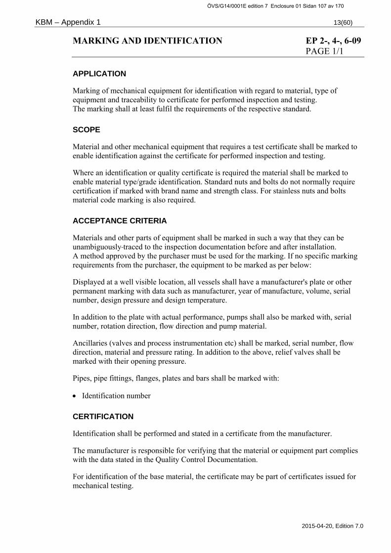
KBM – Appendix 1 13(60)
2015-04-20, Edition 7.0
MARKING AND IDENTIFICATION EP 2-, 4-, 6-09 PAGE 1/1
APPLICATION
Marking of mechanical equipment for identification with regard to material, type of equipment and traceability to certificate for performed inspection and testing. The marking shall at least fulfil the requirements of the respective standard.
SCOPE
Material and other mechanical equipment that requires a test certificate shall be marked to enable identification against the certificate for performed inspection and testing.
Where an identification or quality certificate is required the material shall be marked to enable material type/grade identification. Standard nuts and bolts do not normally require certification if marked with brand name and strength class. For stainless nuts and bolts material code marking is also required.
ACCEPTANCE CRITERIA
Materials and other parts of equipment shall be marked in such a way that they can be unambiguously traced to the inspection documentation before and after installation. A method approved by the purchaser must be used for the marking. If no specific marking requirements from the purchaser, the equipment to be marked as per below:
Displayed at a well visible location, all vessels shall have a manufacturer's plate or other permanent marking with data such as manufacturer, year of manufacture, volume, serial number, design pressure and design temperature.
In addition to the plate with actual performance, pumps shall also be marked with, serial number, rotation direction, flow direction and pump material.
Ancillaries (valves and process instrumentation etc) shall be marked, serial number, flow direction, material and pressure rating. In addition to the above, relief valves shall be marked with their opening pressure.
Pipes, pipe fittings, flanges, plates and bars shall be marked with:
Identification number
CERTIFICATION
Identification shall be performed and stated in a certificate from the manufacturer.
The manufacturer is responsible for verifying that the material or equipment part complies with the data stated in the Quality Control Documentation.
For identification of the base material, the certificate may be part of certificates issued for mechanical testing.
ÖVS/G14/0001E edition 7 Enclosure 01 Sidan 107 av 170

KBM – Appendix 1 14(60)
2015-04-20, Edition 7.0
INSPECTION OF HEAT TREATMENT EP 2-, 3-, 5-10 PAGE 1/1
APPLICATION
Inspection of heat treatment to ensure the application of requirements according to procedure, welding specification or material standard.
SCOPE
According to the procedure for heat treatment or material standard.
TEST REQUIREMENTS
According to the procedure, welding specification or material standard.
ACCEPTANCE CRITERIA
According to the procedure, welding specification or material standard.
CERTIFICATION
The inspection shall be reported in a certificate stating:
Heat treated material or weld joint
Applied procedure
Duration of the heat treatment
Date for the heat treatment
If the recording equipment is used, the temperature diagram to be attached to the record.
The heat treatment certificate of stock/shapes in steel mill may be documented as a heat treatment condition and be part of a certificate issued for the chemical analysis and mechanical testing.
ÖVS/G14/0001E edition 7 Enclosure 01 Sidan 108 av 170

KBM – Appendix 1 15(60)
2015-04-20, Edition 7.0
TEST OF WELD FILLER MATERIAL EP 3-, 5-11 PAGE 1/1
APPLICATION
Testing concerning mechanical properties and analysis of the chemical composition.
SCOPE
All filler material used for welding or weld repairs shall be tested.
TEST REQUIREMENTS
Filler material for the welding of pressure vessels of quality class 1, as well as pumps, valves and piping with DN > 100 / 4” NPS of quality class 1 shall be “check-in tested” according to the following:
A specimen weld in compliance with approved welding procedures for actual application shall be tested according to ASME III, sub article NB-2420 and sub article NB-2430. In austenitic material the content of delta ferrite in the weld deposit must also be determined by direct magnetic measurement or by means of Schaeffler-Delong diagram.
Filler metals for welding of other equipment shall be tested according to the following:
Coated electrodes shall be tested according to, SS-EN 14532-1:2005 or equivalent standard for corresponding material group.
Weld wire shall be tested according to ASME II, SFA-5.9 and SFA-5.18 or other equivalent codes for the corresponding material group.
Filler material for deposition welding (hard facing) shall be tested according to SS-EN 14700:2005
ACCEPTANCE CRITERIA
Filler material shall meet the requirements of the standard specified.
CERTIFICATION
Weld filler material that requires check-in test:
The result shall be reported in inspection certificates, no lower than 3.1 according to SS-EN 10204 or equivalent. The certificate shall contain data of the charge number and test method.
The delta ferrite content of the weld deposit shall also be reported for austenitic material.
Other filler material:
The weld filler material shall be reported according to SS-EN 10204 2.1 alternatively 2.2, the certificate shall contain principle analysis and reference to code.
The supplier shall state that the filler material meets the requirements of applicable standard.
The filler material shall be traceable against the certificate.
A certificate is not required for annually tested approved filler material listed by The Swedish Welding Commission Elektrodportalen © (www.svets.se) or equivalent foreign standard.
ÖVS/G14/0001E edition 7 Enclosure 01 Sidan 109 av 170

KBM – Appendix 1 16(60)
2015-04-20, Edition 7.0
INSPECTION OF WELDING EP 3-, 5-12 PAGE 1/1
APPLICATION
All welding subjected to inspection according to a detailed inspection plan shall be supervised by regularly inspection.
SCOPE
Welding according to the detailed inspection plan.
TEST REQUIREMENTS
Regular inspection of welding in order to ensure:
That the welding is performed in an environment where good result can be achieved.
Examples of factors to be inspected are: cleanliness, dry work area without draught.
That the filler material is stored and handled in an appropriate way.
Examples of factors to be inspected are:
That electrodes are stored in unopened containers or in heated cabinets, that dryers are used at the working site, that TIG wires are marked for prevention of mix up.
That welding methods, filler material, welding equipment, welding parameters and working temperature are correct and are according to the approved welding procedure and drawing.
That applicable welding procedures always are available while welding.
That joint configuration and material surfaces after preparation of weld edge and alignment after tack welding is acceptable in terms of edge misalignment requirements.
That a person with valid authorisation performs the welding.
That all welding is unambiguously traceable to the specific welder.
ACCEPTANCE CRITERIA
Welding shall be performed in accordance with approved drawings and welding procedures by authorised welders and in accordance with the above requirements.
CERTIFICATION
The inspection shall be reported in a certificate verifying that the weld preparation is inspected and that the welding is supervised and performed in a correct manner.
ÖVS/G14/0001E edition 7 Enclosure 01 Sidan 110 av 170

KBM – Appendix 1 17(60)
2015-04-20, Edition 7.0
VISUAL AND DIMENSIONAL INSPECTION EP 2-, 3-, 4-, 5-, 6-13 PAGE 1/1
APPLICATION
Visual and dimensional inspection of material, stock shapes, manufacturing of equipment including parts thereof and installation or repairs.
SCOPE
All materials, stock shapes, equipment parts and weld joints specified in the detailed inspection plans, material standards or specifications shall be inspected.
TEST REQUIREMENTS
Materials, stock shapes and equipment parts shall comply with the dimensions, tolerances, configuration and surface finish specified on the valid drawing or standard.
Welds are to be examined according to SS-EN ISO 17637.
ACCEPTANCE CRITERIA
Welded joints must not have external discontinuities or deviations of shape larger than permitted by quality class "B", i.e. high, according to ISO 5817.
Requirements of freedom from oxides on stainless welded surfaces shall be maintained in accordance with KBM-EP 425.
Equipment, equipment parts and assemblies shall correspond to the measurements, tolerances, performance and surface quality according to valid order and manufacturing document.
CERTIFICATION
For material and shapes, the results shall be reported in an inspection certificate, no lower than 3.1 according to SS-EN 10204 or equivalent.
The certificate may be part of a certificate issued for mechanical testing or chemical analysis.
For welded joints and finished units the result shall be reported in a separate certificate.
At the purchaser's request the inspected dimensions, shapes and position tolerances shall be stated in the certificate.
ÖVS/G14/0001E edition 7 Enclosure 01 Sidan 111 av 170

KBM – Appendix 1 18(60)
2015-04-20, Edition 7.0
PRESSURE AND TIGHTNESS TESTING EP 2-, 4-, 6-14 PAGE 1/3
APPLICATION
Testing concerning the tightness and pressure retaining capability of pressure retaining equipment and parts thereof.
Testing in Sweden shall fulfil the requirements in AFS 2006:8.
The testing shall be carried out after manufacturing and/or after finished installation. Equipment that cannot be pressure tested after installation shall be tested separately prior to installation.
For the manufacture of new parts or a new installation, the area to be inspected shall be tested for tightness and possible deformations prior to possible surface treatment.
SCOPE
All pressure retaining equipment or parts thereof shall be tested. The extent of pressure testing in inspection class 4bkC follows each nuclear plant’s internal routines.
In case of great difficulties or when pressure testing of a particular equipment or part thereof, is considered unsuitable, pressure testing may be replaced by extended non-destructive testing according to chapter 2.1.5.4. (Normally PT/MT according to EP 3/5-16/17 and RT/UT according to EP 3/5-28/24).
The test method and the extent of the replacing method shall be approved by the purchaser and in applicable cases also be reviewed by an Accredited Inspection Body.
TEST REQUIREMENTS
Testing after manufacturing and installation shall normally be carried out with liquid.
If liquid is unsuitable, the testing may be carried out with gas, provided proper precautions against bursting or damages to the equipment are taken.
For testing in Sweden, permission must be obtained according to regulations stated by the Swedish Board for Occupational Safety and Health.
Pipes and pipe fittings, either seamless or continuously automatically welded:
Pressure tested according to technical delivery and inspection requirements for material standard approved for the actual application. The pressure shall be maintained during a sufficiently long time to detect leakage.
At ”piece production” of pipe fittings and flanges in quality class 1-4 and 4A are pressure testing not required.
Pipes, pipe fittings and flanges are normally pressure- and tightness tested in conjunction with pre-fabrication or as an installed system.
ÖVS/G14/0001E edition 7 Enclosure 01 Sidan 112 av 170

KBM – Appendix 1 19(60)
2015-04-20, Edition 7.0
PRESSURE AND TIGHTNESS TESTING EP 2-, 4-, 6-14 PAGE 2/3 Open tanks:
By water filling and with a holding time of at least 30 minutes.
Other pressure retaining equipment or parts thereof:
Pressure testing as per approved design drawing. In case this information is lacking on the drawing, the test pressure shall normally be 1,5 times the design pressure for equipment made of steel castings and 1,3 times the design pressure for equipment made of other metallic materials.
The pressure shall be maintained for a sufficiently long period of time to detect leakage.
At design and manufacturing of new pressure retaining equipment according to the requirements in AFS 1999:4 (PED) shall the pressure testing be performed with 1,43 x the design pressure or other higher prescribed value.
Pressure testing of installation:
The testing of a finished installation shall follow an approved pressure- and tightness testing program.
Normally the test pressure is 1,3 times the design pressure with the necessary holding time to disclose leaks and other deficiencies. The minimum holding time is 15 minutes.
Test pressure for new installations in quality class 4 shall normally follow the requirements in AFS 1999:4 (PED) i.e. pressure testing is performed with 1,43 x the design pressure or other higher prescribed value.
For parts that connects to existing parts in nuclear facilitys shall pressure according to 1,3 times the design pressure be applied and with the necessary holding time to disclose leaks and other deficiencies.
The program for pressure- and tightness test shall contain data regarding:
Drawings and inspection plan
Boundaries for the extent of the pressure test (to be specified on drawings or system flowcharts)
Test pressure, test medium and holding time at full test pressure
Connection points, valve positions (closed/open) and blindings
Parts to be protected during the pressure test
Venting procedure
Location for pressure gauges and location for verification gauge
Method and extent of inspection
Restoration of the system after the pressure test (requires sign off after restoration)
Risk analyses
ÖVS/G14/0001E edition 7 Enclosure 01 Sidan 113 av 170

KBM – Appendix 1 20(60)
2015-04-20, Edition 7.0
PRESSURE AND TIGHTNESS TESTING EP 2-, 4-, 6-14 PAGE 3/3 At manufacturing and installation in quality class 4, the pressure and holding times
according to AFS 1999:4 are valid for new equipment and assemblies. For parts that connects to existing parts in nuclear facilitys, the pressure according to the second section above applies.
Exemptions:
Pressure test is normally not required for the following cases:
replacement of bolts and nuts
buttering at nominal wall thickness
replacement of blind flanges
welding of details such as lugs, lifting ears etc, against pressure retaining parts
Weld repairs replacing less than 20% of the nominal wall thickness of the base material for t 25 mm and less than 10% of the nominal wall thickness for t > 25 mm
plugging of heat exchanger tubes
replacement of a small number ( 10%) of heat exchanger tubes
seal welds
compression or swage ring couplings, providing that inspection of ring installation was carried out
ACCEPTANCE CRITERIA
Leakage or permanent deformities are not allowed.
CERTIFICATION
The result of the testing shall be reported in a record stating the test of:
Device, part of device or extent of the test
Reference to drawing and inspection plan
Identity marking
Test medium
Test pressure, temperature and holding time
Result of the testing
The test certificate for pressure and tightness testing of pipes in pipe mills may be part of a certificate issued for other tests.
ÖVS/G14/0001E edition 7 Enclosure 01 Sidan 114 av 170
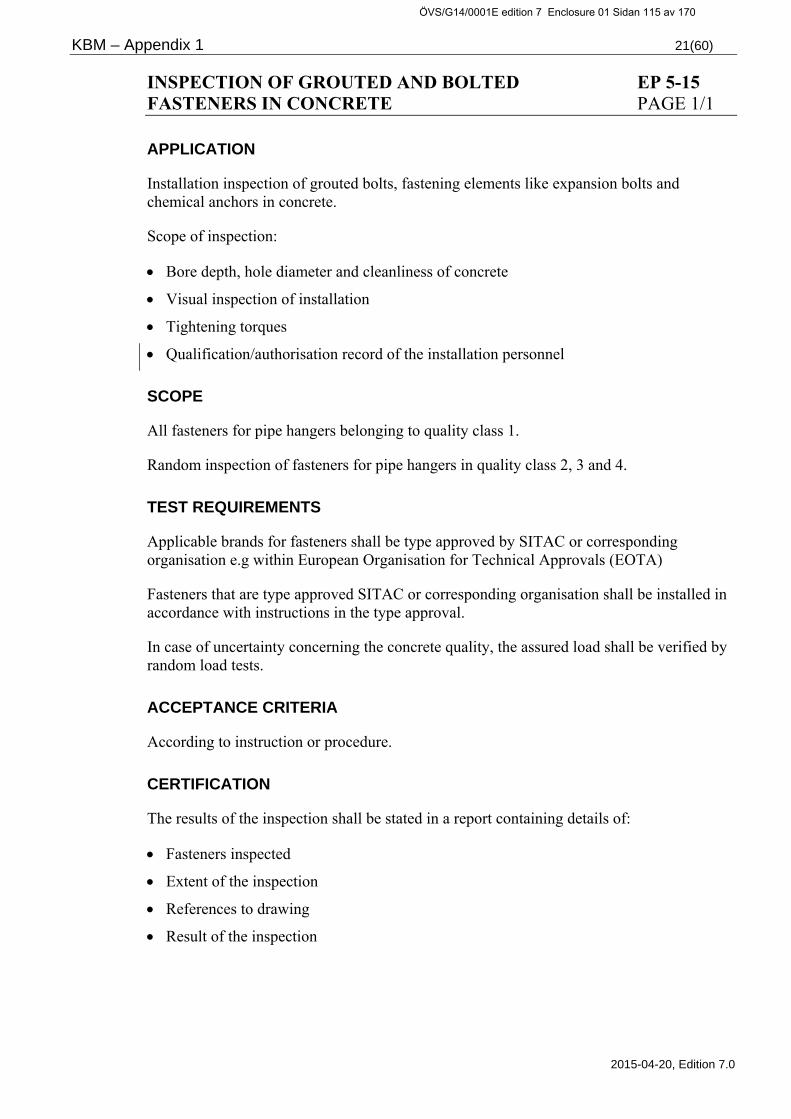
KBM – Appendix 1 21(60)
2015-04-20, Edition 7.0
INSPECTION OF GROUTED AND BOLTED EP 5-15 FASTENERS IN CONCRETE PAGE 1/1
APPLICATION
Installation inspection of grouted bolts, fastening elements like expansion bolts and chemical anchors in concrete.
Scope of inspection:
Bore depth, hole diameter and cleanliness of concrete
Visual inspection of installation
Tightening torques
Qualification/authorisation record of the installation personnel
SCOPE
All fasteners for pipe hangers belonging to quality class 1.
Random inspection of fasteners for pipe hangers in quality class 2, 3 and 4.
TEST REQUIREMENTS
Applicable brands for fasteners shall be type approved by SITAC or corresponding organisation e.g within European Organisation for Technical Approvals (EOTA)
Fasteners that are type approved SITAC or corresponding organisation shall be installed in accordance with instructions in the type approval.
In case of uncertainty concerning the concrete quality, the assured load shall be verified by random load tests.
ACCEPTANCE CRITERIA
According to instruction or procedure.
CERTIFICATION
The results of the inspection shall be stated in a report containing details of:
Fasteners inspected
Extent of the inspection
References to drawing
Result of the inspection
ÖVS/G14/0001E edition 7 Enclosure 01 Sidan 115 av 170

KBM – Appendix 1 22(60)
2015-04-20, Edition 7.0
LIQUID PENETRANT TESTING EP 2-, 3-, 4-, 5-16 PAGE 1/5
APPLICATION
The testing applies to surface breaking discontinuities in weld joints, surface welds, sealing surfaces and other surfaces of mechanical equipment or parts thereof.
The inspection shall be carried out on the final surface, after forming, heat treatment and machining.
SCOPE
At manufacturing, installation and repair the following shall be tested:
Weld bevels, surfaces to be welded, welded joints including heat affected zones, buttering welds, surface welds and surfaces machined to final surface.
The applicable inspection plan shall give the detailed extent of the testing.
The below is the principle for application and extent of testing:
1. Pressure retaining equipment or parts thereof
1.1 Details of forgings and bars
Quality class 1 and 2:
Accessible surfaces and weld bevels as well as special surfaces according to section 2.
Quality class 3-4:
Special surfaces according to section 2.
1.2 Castings
Quality class 1-2:
Assessible surfaces and weld bevels as well as special surfaces according to section 2.
Quality class 3-4:
Weld ends
Special surfaces according to section 2.
1.3 Plate details
Quality class 1-2:
Weld bevels and special surfaces according to section 2.
Quality class 3-4:
Special surfaces according to section 2.
ÖVS/G14/0001E edition 7 Enclosure 01 Sidan 116 av 170

KBM – Appendix 1 23(60)
2015-04-20, Edition 7.0
LIQUID PENETRANT TESTING EP 2-, 3-, 4-, 5-16 PAGE 2/5
1.4 Pipes and pipe fittings
Quality class 1, 100% and random examination in quality class 2:
Cold worked sections after bending of pipes and pipe fittings as follows:
Stainless pipes and pipe fittings where R < 2,5x OD
Ferritic pipes and pipe fittings where R < 6x OD
R = mean bending radius
OD = nominal outside diameter
Weld edges and special surfaces according to section 2.
Quality class 3 and 4:
Special surfaces according to section 2.
1.5 Bolts and nuts, special
Quality class 1-4
Accessible surfaces
1.6 Bolts and nuts, standard
Quality class 1, 100% and quality class 2, random test:
Accessible surfaces with a thread diameter > M 24 / 1".
1.7 Bellows, pressure vessels and pipes
Quality class1 and 2:
Accessible surfaces, weld bevels and special surfaces according to section 2.
1.8 Bellows for valves and valve closing devices
Quality class 1 and 2:
Accessible surfaces
Quality class 3 and 4:
Accessible surfaces for valves DN>150 / 6” NPS.
Quality class 1-4:
Surfaces to be surfaces welded.
ÖVS/G14/0001E edition 7 Enclosure 01 Sidan 117 av 170

KBM – Appendix 1 24(60)
2015-04-20, Edition 7.0
LIQUID PENETRANT TESTING EP 2-, 3-, 4-, 5-16 PAGE 3/5
2. Weld bevels and special surfaces
2.1 Weld bevels
Quality class 1-4:
All weld bevels in castings, other weld bevels in quality class 1 and 2 where the nominal thickness of the material is > 10 mm
2.2 Special surfaces
Quality class 1-4:
All surfaces where temporary welds have been removed.
Quality class 1 and 2:
Surfaces to be surface welded.
Cold deformed areas.
Surfaces where a visual inspection indicates the necessity.
3. Weld joints in pressure retaining and load bearing parts
3.1 Vessels, pipelines, welded pipes and fittings
Butt weld:
Quality class 1: Full extent
Other weld joints and dissimilar welds:
Quality class 1-4: Full extent
(For class 4 ic C a normal visual inspection according to EP 3/5-13 is sufficient)
Surfaces where a visual inspection indicates the necessity.
3.2 Welds in supports for piping DN>50 / 2” NPS
Quality class 1-3: 10%
Quality class 4: Surfaces where a visual inspection indicates the necessity.
3.3 Pipe rupture restraints
Weld joints: 10%
ÖVS/G14/0001E edition 7 Enclosure 01 Sidan 118 av 170

KBM – Appendix 1 25(60)
2015-04-20, Edition 7.0
LIQUID PENETRANT TESTING EP 2-, 3-, 4-, 5-16 PAGE 4/5
3.4 Pumps, valves and in-line instruments
Butt weld:
Quality class 1-2: Full extent
Quality class 3-4: Surfaces where a visual inspection has indicated the necessity.
Other weld joints:
Quality class 1-4: Full extent
(For class 4 ic C a normal visual inspection according to EP 3/5-13 is sufficient.)
3.5 Surfacing of valve closing devices and of pressure retaining valve seats
Quality class 1-4: Full extent for valves DN > 25 / 1” NPS
TEST REQUIREMENTS
The testing shall be performed according to one of the following alternatives:
SS-EN ISO 3452-1 Non-destructive testing - Penetrant testing - Part1: General principles
SS-EN 1371-1 Founding - Liquid penetrant testing - Part 1: Sand, gravity die and low pressure die castings
SS-EN 10228-2 Non-destructive testing of steel forgings - Part 2: Penetrant testing
ASME V article 6 Liquid Penetrant Examination
Other equivalent foreign standard for testing can be used only after approval of the purchaser.
Penetrant fluids used for testing austenitic stainless steel, titanium alloys or nickel alloys shall be analysed and meet the requirements in ASME V, paragraph T-641.
The analysis shall be carried out on every lot of penetrant fluids. Every package must be marked with the lot number and be traceable to its certificate of analysis.
ACCEPTANCE CRITERIA
Tested surfaces must not have cracks or any other surfacing discontinuities, which can cause indications to a larger extent than stated below.
ÖVS/G14/0001E edition 7 Enclosure 01 Sidan 119 av 170

KBM – Appendix 1 26(60)
2015-04-20, Edition 7.0
LIQUID PENETRANT TESTING EP 2-, 3-, 4-, 5-16 PAGE 5/5
1. General requirements
1.1 Sealing surfaces and seal welds
No indications accepted.
1.2 Weld joints and adjoining heat-affected zone, single-run, pressure retaining part
No indications accepted.
1.3 Other weld joints and adjoining heat-affected zone
Acceptance level 1 according to SS-EN ISO 23277.
1.4 Surface deposit material (not sealing surfaces)
Acceptance level 2 according to SS- EN ISO 23277.
1.5 Other surfaces including weld bevels
Acceptance level 1 according to SS-EN ISO 23277.
1.6 Castings excluding weld bevels
Acceptance level SP 1, CP 1, LP 1, AP 1 according to SS-EN 1371-1 unless otherwise agreed.
1.7 Steel forgings
Acceptance level quality class 4 according to SS-EN 10228-2.
1.8 Bolts and nuts
Linear indications are not accepted. Acceptance level 1 for non-linear indications.
Type of indication Acceptance level 1 2 3 Linear indication l = length of indication
l < 2 l < 4 l < 8
Non-linear indication d = major axis dimension
d < 4 d < 6 d < 8
Acceptance levels 2 and 3 may be specified with a suffix “X” which denotes that all linear indications detected shall be evaluated to level 1.
Table 1 Acceptance levels according to SS-EN-ISO-23277
CERTIFICATION
Test report to be prepared containing at least information as per SS-EN ISO 3452-1.
ÖVS/G14/0001E edition 7 Enclosure 01 Sidan 120 av 170

KBM – Appendix 1 27(60)
2015-04-20, Edition 7.0
MAGNETIC PARTICLE TESTING EP 2-, 3-, 4-, 5-17 PAGE 1/5
APPLICATION
The inspection concerns surface breaking discontinuities in weld joints, surface welds, sealing surfaces and other surfaces of mechanical equipment or parts thereof made of ferro-magnetic material.
The inspection shall be carried out on the final surface, after forming, heat treatment and machining.
SCOPE
At manufacturing, installation and repair, the following shall be tested:
Weld bevels, surfaces to be welded, welded joints including heat-affected zones, buttering welds, surface welds and surfaces machined to final surface.
The applicable inspection plan shall give the detailed extent of the testing.
The principle for the application and extent of testing the following applies:
1. Pressure retaining equipment or parts thereof
1.1 Details of forgings and bars
Quality class 1 and 2:
Accessible surfaces and weld bevels as well as special surfaces according to section 2.
Quality class 3-4:
Special surfaces according to section 2.
1.2 Castings
Quality class 1 and 2:
Accessible surfaces and weld bevels as well as special surfaces according to section 2.
Quality class 3-4:
Weld ends
Special surfaces according to section 2
ÖVS/G14/0001E edition 7 Enclosure 01 Sidan 121 av 170

KBM – Appendix 1 28(60)
2015-04-20, Edition 7.0
MAGNETIC PARTICLE TESTING EP 2-, 3-, 4-, 5-17 PAGE 2/5
1.3 Plate and sheet
Quality class 1 and 2:
Weld bevels and special surfaces according to section 2.
Quality class 3-4:
Special surfaces according to section 2.
1.4 Pipes and pipe fittings
Quality class 1, 100% and quality class 2, random test.
Cold worked sections following bending of pipes and pipe fittings as follows:
Ferritic pipes and pipe fittings where R < 6xOD.
R = mean bending radius
OD = nominal outside diameter
Weld edges and special surfaces according to section 2.
Quality class 3-4:
Special surfaces according to section 2.
1.5 Bolts and nutss, special
Quality class 1-4
Accessible surfaces
1.6 Bolts and nuts, standard
Quality class 1, 100% and quality class 2, random test:
Accessible surfaces with a thread diameter > M 24 / 1".
1.7 Bellows, pressure vessels and pipes
Quality class 1-2:
Accessible surfaces and weld bevels as well as special surfaces according to section 2.
ÖVS/G14/0001E edition 7 Enclosure 01 Sidan 122 av 170

KBM – Appendix 1 29(60)
2015-04-20, Edition 7.0
MAGNETIC PARTICLE TESTING EP 2-, 3-, 4-, 5-17 PAGE 3/5
1.8 Bellows for valves and valve closing devices
Quality class 1-2:
Accessible surfaces
Quality class 3-4:
Accessible surfaces for valves DN > 150 / 6” NPS.
Quality class 1-4:
Surfaces to be surface welded.
2. Weld bevels and special surfaces
2.1 Weld bevels
Quality class 1-4:
All weld bevels in castings, other weld bevels in quality class 1 and 2 where the nominal thickness of material is > 10 mm.
2.2 Special surfaces
Quality class 1-4:
All surfaces where temporary welds have been removed.
Quality class 1-2:
Surfaces to be surfaces welded.
Cold deformed areas.
Surfaces where a visual inspection has indicated the necessity.
3. Weld joints in pressure retaining and load bearing parts
3.1 Vessels, pipelines, welded pipes and fittings
Butt weld:
Quality class 1: Full extent
Other weld joints:
Quality class 1-4: Full extent
(For class 4 ic C normally a visual inspection according to EP 3/5-13 is sufficient).
Surfaces where a visual inspection has indicated the necessity.
ÖVS/G14/0001E edition 7 Enclosure 01 Sidan 123 av 170

KBM – Appendix 1 30(60)
2015-04-20, Edition 7.0
MAGNETIC PARTICLE TESTING EP 2-, 3-, 4-, 5-17 PAGE 4/5
3.2 Welds in supports for piping DN>50 / 2” NPS
Quality class 1-3: 10%
Quality class 4: Surfaces where a visual inspection has indicated the necessity.
3.3 Pipe rupture restraints
Weld joints: 10%
3.4 Pumps, valves and in-line instruments
Butt weld:
Quality class 1-2: Full extent
Quality class 3-4: Surfaces where a visual inspection has indicated the necessity.
Other weld joints:
Quality class 1-4: Full extent
(For class 4 ic C normally a visual inspection according to EP 3/5-13 is sufficient).
TEST REQUIREMENTS
The testing shall be performed according to one of the following alternatives:
SS-EN ISO 9934-1 Non-destructive testing - Magnetic particle testing - Part 1: General principles
SS-EN ISO 17638 Non-destructive testing of welds - Magnetic particle testing
SS-EN 1369 Founding - Magnetic particle testing
SS-EN 10228-1 Non-destructive testing of steel forgings - Part 1: Magnetic particle inspection
ASME V article 7 Magnetic Particle Examination
Other equivalent foreign standard for testing can be used only after approval of the purchaser.
Magnetic particle examination shall be done in two opposite perpendicular directions. Contrast aid shall be used if needed.
Sealing surfaces and surface welds shall be tested by penetrant testing according to inspection procedure KBM EP-16.
ÖVS/G14/0001E edition 7 Enclosure 01 Sidan 124 av 170

KBM – Appendix 1 31(60)
2015-04-20, Edition 7.0
MAGNETIC PARTICLE TESTING EP 2-, 3-, 4-, 5-17 PAGE 5/5
ACCEPTANCE CRITERIA
Tested surfaces must not have cracks or other surface breaking discontinuities, which will cause indications to a larger extent than specified below.
1. General requirements
1.2 Weld joints and adjoining heat-affected zone, single-run, pressure retaining parts:
No indications accepted.
1.3 Other weld joints and adjoining heat-affected zone.
Acceptance level 1 according to SS-EN ISO 23278.
1.5 Other surfaces including weld bevels
Acceptance level 1 according to SS-EN ISO 23278.
1.6 Castings excluding weld bevels
Acceptance level SM 1, LM 1, AM 1 according to SS-EN 1369 unless otherwise agreed.
1.7 Steel forgings
Acceptance level quality class 4 according to SS-EN 10228-1.
1.8 Bolts and nuts
Linear indications are not accepted. Acceptance level 1 for non-linear indications.
Type of indication Acceptance level 1 2 3 Linear indication l = length of indication
l < 1,5 l < 3 l < 6
Non-linear indication d = major axis dimension
d < 2 d < 3 d < 4
Acceptance level 2 and 3 may be specified with a suffix ”X” which denotes that all linear indications detected shall be evaluated to level 1.
Table 2 Acceptance levels according to SS-EN ISO 23278
CERTIFICATION
Test report to be prepared containing at least information as per SS-EN-ISO 17638. For castings SS-EN 9934-1 applies.
ÖVS/G14/0001E edition 7 Enclosure 01 Sidan 125 av 170

KBM – Appendix 1 32(60)
2015-04-20, Edition 7.0
INDUCTIVE TESTING OF MATERIAL EP 2-, 3-, 4-, 5-18 AND WELDS PAGE 1/1
APPLICATION
As an alternative for PT and MT according to KBM-EP 2-, 3-, 5-16 or -17 inductive testing (ET) can be used.
SCOPE
According to KBM-EP 2-, 3-, 5-16 or -17.
TEST REQUIREMENTS
The testing shall be performed according to:
SS-EN 1711 Non-destructive examination of welds - Eddy current examination of welds by complex plane analysis
and one for the application prepared detailed examination procedure.
ACCEPTANCE CRITERIA
The evaluation shall be performed based upon the requirement for the object in question as per the detailed testing procedure.
CERTIFICATION
The results of the inspection shall be reported in a test report containing at least information as per SS-EN 1711 chapter 7.
ÖVS/G14/0001E edition 7 Enclosure 01 Sidan 126 av 170

KBM – Appendix 1 33(60)
2015-04-20, Edition 7.0
IN-PROCESS INDUCTIVE TESTING OF TUBES EP 2-19 FOR HEAT EXCHANGERS PAGE 1/1
APPLICATION
Testing for detection of discontinuities oriented longitudinally and laterally to the circumference of the tubes.
A procedure for testing the tubes in question shall be drawn up and approved by the purchaser.
The testing shall be carried out on the finished surface after forming, heat treatment and machining.
SCOPE
Quality class 1-3: Material for heat exchanger tubes with an outside diameter OD < 25 mm, and wall thickness t < 1,5 mm, shall be fully tested.
TEST REQUIREMENTS
Depending on the tube material, the testing shall be carried out according to an approved procedure, meeting the requirements of the standards in table 3.
ACCEPTANCE CRITERIA
See table “Test standards”.
CERTIFICATION
The results of the test shall be recorded in a report with details of the test object, procedure, extent, equipment, results and date as well as name and qualification level of the operator conducting the test.
Material Standard
Ferromagnetic steel ASME V SE-309
Austenitic stainless steel ASME V SE-426
Cupper alloys ASME V SE-243
Nickel based alloys ASME V SE-571
”Steel pipes” SS/CS SS-EN ISO 15549
Table 3 Test standards
EN-standards such as SS-EN 10893 and SS-EN 1971 and similar may also be used.
ÖVS/G14/0001E edition 7 Enclosure 01 Sidan 127 av 170

KBM – Appendix 1 34(60)
2015-04-20, Edition 7.0
POST PRODUCTION ULTRASONIC TESTING OF EP 2-20 PLATE PAGE 1/2
APPLICATION
Testing concerning lamination in plate and lamination or incomplete bonding in compound materials. Compound material means plating applied by rolling or explosive cladding.
The testing shall be performed after forming and heat treatment.
SCOPE
Plate of thickness > 6 mm shall be tested according to extent of table 4.
TEST REQUIREMENTS
Ultrasonic testing shall be carried out according to SS-EN 10160 or SS-EN 10307.
If other equivalent method is preferred, it must prior to the test be approved by the purchaser.
For testing of plate for welding plates and plate exposed to local lateral loads, the test equipment shall be calibrated towards reference blocks with flat-bottom holes, alternatively AVG-scales, AVG-diagrams or equivalent aids.
ACCEPTANCE CRITERIA
Lamination is not accepted in the following areas:
1. Plate and compound materials
Each area with lamination which causes a complete loss of the bottom echo and which cannot be inscribed in a circle with a diameter of 36 mm or half of the plate thickness, whichever is larger.
Each area where two or more laminations larger than or equal to 50 % of the original bottom echo and simultaneously a decrease of the bottom echo to 50% or more which cannot be inscribed in a circle with a diameter of 36 mm or half of the plate thickness, whichever is larger.
Two or more adjacent areas with lamination smaller than the above mentioned, shall be regarded as one area if the distance between them is less than the inscribed diameter of the larger area.
Complete loss of the bottom echo means that the bottom echo is less than 5% of calibrated amplitude on the screen.
Alternative acceptance level according to SS-EN 10160 class S2 or SS-EN 10307 class S2. For edge zones SS-EN 10160 table 5 class E3 applies to both feritic and austenitic plates.
ÖVS/G14/0001E edition 7 Enclosure 01 Sidan 128 av 170

KBM – Appendix 1 35(60)
2015-04-20, Edition 7.0
POST PRODUCTION ULTRASONIC TESTING OF EP 2-20 PLATE PAGE 2/2
2. Areas exposed to lateral loads and plate for welding plates
Lamination with indications larger than a flat bottom hole with a diameter of 8 mm are not acceptable.
The number of indications producing echoes corresponding to flat bottom holes with diameters between 5 and 8 mm must not exceed 3 per dm².
Alternative acceptance level according to SS-EN 10160 class S3 or SS-EN 10307 class S3. For edge zones SS-EN 10160 table 5 class E4 applies to both feritic and austenitic plates.
CERTIFICATION
Test reports shall be prepared and contain at least the following:
Complete identification of the tested item. The condition of the test surface. Test method, equipment, type, model, and device number. Probe, type, model, frequency and size of crystal. Reference amplification. Scanning method and coupling agent. Calibration method, possible reference blocks. Corrections, if any. Reference to applied test standards and KBM inspection procedures or detailed procedures. Test results and extent of inspection. Name and date and the operator’s level of qualification. Alternatively test report according to SS-EN 10160.
t i mm Plate for pressure retaining equipment
Quality Classes 1 2
Plate for pressure retaining and/or load bearing equipment exposed to lateral loads
Plate for welding plates
6 – (15) 100 mm1 100 mm1,4 100 %2 100 %3, 5
15 - 100 % 100 mm1 100 %2 100 %3,5 Table 4 Extent of inspection, UT, - Plate and Compound material
1) Testing of the plate across a 100 mm square grid.
2) For local lateral load the width of the test area must be the highest value of 50 mm or the load engagement plus twice the thickness of the connecting plate. The area around holes will be tested only if DN > 50 / 2” NPS (diameter of hole larger than 50 mm).
3) “S-plate” tested as per SS-EN 10160 class S3/E4 or SS-EN 10307 S3/E4 is accepted.
4) For base material to welded pipes and piping DN>100 / 4” NPS and PN>40 bar g.
5) “Z-plate” tested as per SS-EN 10164 is accepted for welding plates. Acceptance criteria as per table 1, quality class min. Z25.
ÖVS/G14/0001E edition 7 Enclosure 01 Sidan 129 av 170
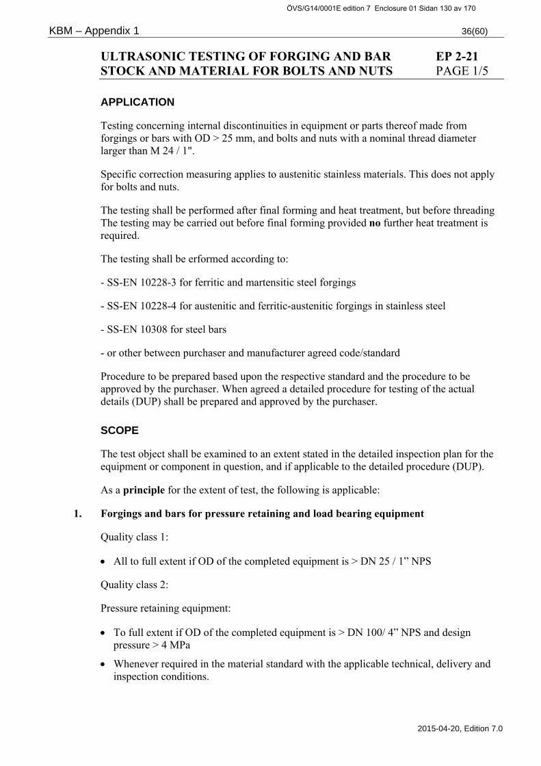
KBM – Appendix 1 36(60)
2015-04-20, Edition 7.0
ULTRASONIC TESTING OF FORGING AND BAR EP 2-21 STOCK AND MATERIAL FOR BOLTS AND NUTS PAGE 1/5
APPLICATION
Testing concerning internal discontinuities in equipment or parts thereof made from forgings or bars with OD > 25 mm, and bolts and nuts with a nominal thread diameter larger than M 24 / 1".
Specific correction measuring applies to austenitic stainless materials. This does not apply for bolts and nuts.
The testing shall be performed after final forming and heat treatment, but before threading The testing may be carried out before final forming provided no further heat treatment is required.
The testing shall be erformed according to:
- SS-EN 10228-3 for ferritic and martensitic steel forgings
- SS-EN 10228-4 for austenitic and ferritic-austenitic forgings in stainless steel
- SS-EN 10308 for steel bars
- or other between purchaser and manufacturer agreed code/standard
Procedure to be prepared based upon the respective standard and the procedure to be approved by the purchaser. When agreed a detailed procedure for testing of the actual details (DUP) shall be prepared and approved by the purchaser.
SCOPE
The test object shall be examined to an extent stated in the detailed inspection plan for the equipment or component in question, and if applicable to the detailed procedure (DUP).
As a principle for the extent of test, the following is applicable:
1. Forgings and bars for pressure retaining and load bearing equipment
Quality class 1:
All to full extent if OD of the completed equipment is > DN 25 / 1” NPS
Quality class 2:
Pressure retaining equipment:
To full extent if OD of the completed equipment is > DN 100/ 4” NPS and design pressure > 4 MPa
Whenever required in the material standard with the applicable technical, delivery and inspection conditions.
ÖVS/G14/0001E edition 7 Enclosure 01 Sidan 130 av 170

KBM – Appendix 1 37(60)
2015-04-20, Edition 7.0
ULTRASONIC TESTING OF FORGING AND BAR EP 2-21 STOCK AND MATERIAL FOR BOLTS AND NUTS PAGE 2/5
Load bearing equipment:
Whenever required in the material standard with the applicable technical, delivery and inspection conditions.
If required due to the design with regard to loads and strength margins.
If required by the purchaser.
Quality class 3-4:
Pressure retaining equipment:
Whenever required in the material standard with the applicable technical, delivery and inspection conditions.
Load bearing equipment:
Whenever required in the material standard with the applicable technical, delivery and inspection conditions.
If required with regard to loads and strength margins.
If required by the purchaser.
2. Material for bolts and nuts, "special"
Quality class 1-2:
All to full extent if OD > M 24 / 1".
Whenever required in the material standard with the applicable technical, delivery and inspection conditions.
3. Material for blots and nuts, "standard"
All quality classes:
Whenever required in the material standard with the applicable technical, delivery and inspection conditions.
ÖVS/G14/0001E edition 7 Enclosure 01 Sidan 131 av 170
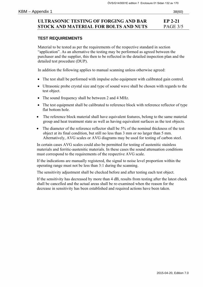
KBM – Appendix 1 38(60)
2015-04-20, Edition 7.0
ULTRASONIC TESTING OF FORGING AND BAR EP 2-21 STOCK AND MATERIAL FOR BOLTS AND NUTS PAGE 3/5
TEST REQUIREMENTS
Material to be tested as per the requirements of the respective standard in section “application”. As an alternative the testing may be performed as agreed between the purchaser and the supplier, this then to be reflected in the detailed inspection plan and the detailed test procedure (DUP).
In addition the following applies to manual scanning unless otherwise agreed:
The test shall be performed with impulse echo equipment with calibrated gain control.
Ultrasonic probe crystal size and type of sound wave shall be chosen with regards to the test object.
The sound frequency shall be between 2 and 4 MHz.
The test equipment shall be calibrated to reference block with reference reflector of type flat bottom hole.
The reference block material shall have equivalent features, belong to the same material group and heat treatment state as well as having equivalent surfaces as the test objects.
The diameter of the reference reflector shall be 5% of the nominal thickness of the test object at its final condition, but still no less than 3 mm or no larger than 5 mm. Alternatively, AVG scales or AVG diagrams may be used for testing of carbon steel.
In certain cases AVG scales could also be permitted for testing of austenitic stainless materials and ferritic-austenitic materials. In these cases the sound attenuation conditions must correspond to the requirements of the respective AVG scale.
If the indications are manually registered, the signal to noise level proportion within the operating range must not be less than 3:1 during the scanning.
The sensitivity adjustment shall be checked before and after testing each test object.
If the sensitivity has decreased by more than 4 dB, results from testing after the latest check shall be cancelled and the actual areas shall be re-examined when the reason for the decrease in sensitivity has been established and required actions have been taken.
ÖVS/G14/0001E edition 7 Enclosure 01 Sidan 132 av 170

KBM – Appendix 1 39(60)
2015-04-20, Edition 7.0
ULTRASONIC TESTING OF FORGING AND BAR EP 2-21 STOCK AND MATERIAL FOR BOLTS AND NUTS PAGE 4/5
Specific correction measurements of sound attenuation:
In order to determine the testability for further in service inspection of austenitic stainless materials, specific correction measurements of sound attenuation shall be taken on forgings with weld ends in quality class 1 and 2 and also in other quality classes if agreed between the purchaser and the manufacturer.
These examinations to be performed according to SS-EN ISO 16811 section 6.5.3 and also in compliance with the stipulations of the section Test requirements above.
Scanning
The scanning direction must be adapted to the geometry of the test object and the possible defects the manufacturing process in question might cause. The whole volume of the test object shall be scanned with a normal scanner in two directions approximately perpendicular to each other.
As an alternative, or, if required by the purchaser, forged material shall be scanned with an angle probe if the total volume cannot be tested with standard probe.
When testing is performed prior to the final machining e.g. solid forgings for valves, T-pieces etc. the material volume to be removed can be disregarded at testing and calibration.
Detailed procedure description (DUP)
The detailed procedure, if agreed, shall contain at least the following data:
Description of the test object
Reference to the inspection plan
Standard for test / procedure
Reference reflector
Probe
Ultrasonic test apparatus
Description of method for measuring of sound attenuation
Description of certain measurements of sound attenuation
Scanning area and scanning directions
Couplant
Acceptance criteria
ÖVS/G14/0001E edition 7 Enclosure 01 Sidan 133 av 170

KBM – Appendix 1 40(60)
2015-04-20, Edition 7.0
ULTRASONIC TESTING OF FORGING AND BAR EP 2-21 STOCK AND MATERIAL FOR BOLTS AND NUTS PAGE 5/5
ACCEPTANCE CRITERIA
Unless other agreed between purchaser and supplier, below acceptance criteria apply.
The following applies to discontinuities:
Stainless forgings according to SS-EN 10228 quality class 3
Ferritic forgings according to SS-EN 10228 quality class 4
Stainless bar material SS-EN 10308 quality class 3
Ferritic bar material SS-EN 10308 quality class 4
For specific correction measurements of stainless steel forgings the below acceptance criteria applies:
When ΔVt ≥ 10dB the purchaser to be contacted for decision and further action.
Note that high attenuation and/or significant variations in attenuation in forgings may be caused due to course grain size. Examination of grain size then to be considered as per KBM EP 2-08.
CERTIFICATION
A test report shall be prepared and contain at least the following:
Complete identification of the test object.
The condition of the test surface.
Test method.
Test apparatus, type, model, and apparatus number.
Probe, type, model, frequency and size of crystal.
Reference amplification.
Scanning method and coupling agent.
Calibration method, possible reference blocks.
Corrections, if any.
References to applied testing standard, KBM inspection procedure or detailed procedure.
Result and reporting of specific correction measurements and signal/noise conditions
Name and date and the operator's qualification level.
ÖVS/G14/0001E edition 7 Enclosure 01 Sidan 134 av 170

KBM – Appendix 1 41(60)
2015-04-20, Edition 7.0
IN-PROCESS ULTRASONIC TESTING OF PIPES EP 2-22 PAGE 1/3
APPLICATION
Testing to detect discontinuities oriented longitudinally and laterally to the circumference direction of the pipes. The plate raw material for welded pipes with a thickness of > 6 mm in quality classes 1 and 2 shall be tested and meet the requirements in KBM EP 2-20.
SCOPE
The material in pipes shall be tested to the full extent with regard to longitudinal and transversal defects.
As a principle for the testing the following is applicable:
1. Pipes
Quality class 1:
All pipes to full extent
Quality class 2:
Pipes with DN > 100 / > 4” NPS (OD 114,3 mm) with a design pressure > 4 MPa shall be tested to full extent.
Weld seams in longitudinally welded pipes shall be tested in full extent regardless of dimension and design pressure. Alternative testing according to EP 3-28.
Whenever required in material standard with applicable technical-, delivery- and inspection requirements.
Quality class 3-4
Weld seams in longitudinally welded pipes with a weld joint efficiency factor (z) = 1,0 shall be tested to full extent. Alternative testing according to EP 3-28.
Whenever required in material standard with applicable technical-, delivery- and inspection requirements.
TEST REQUIREMENTS
Tests shall be performed according to an approved detailed procedure. The procedure shall be based on a well proven standard that, through experience, has shown the ability to detect manufacturing defects that may occur during the manufacturing process.
ÖVS/G14/0001E edition 7 Enclosure 01 Sidan 135 av 170
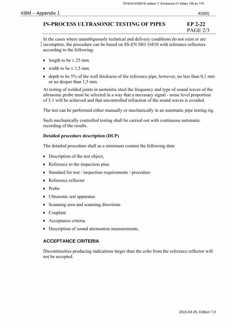
KBM – Appendix 1 42(60)
2015-04-20, Edition 7.0
IN-PROCESS ULTRASONIC TESTING OF PIPES EP 2-22 PAGE 2/3
In the cases where unambiguously technical and delivery conditions do not exist or are incomplete, the procedure can be based on SS-EN ISO 16810 with reference reflectors according to the following:
length to be 25 mm.
width to be 1,5 mm.
depth to be 5% of the wall thickness of the reference pipe, however, no less than 0,1 mm or no deeper than 1,5 mm.
At testing of welded joints in austenitic steel the frequency and type of sound waves of the ultrasonic probe must be selected in a way that a necessary signal - noise level proportion of 3:1 will be achieved and that uncontrolled refraction of the sound waves is avoided.
The test can be performed either manually or mechanically in an automatic pipe testing rig.
Such mechanically controlled testing shall be carried out with continuous automatic recording of the results.
Detailed procedure description (DUP)
The detailed procedure shall as a minimum contain the following data:
Description of the test object,
Reference to the inspection plan
Standard for test / inspection requirements / procedure
Reference reflector
Probe
Ultrasonic test apparatus
Scanning area and scanning directions
Couplant
Acceptance criteria
Description of sound attenuation measurements.
ACCEPTANCE CRITERIA
Discontinuities producing indications larger than the echo from the reference reflector will not be accepted.
ÖVS/G14/0001E edition 7 Enclosure 01 Sidan 136 av 170

KBM – Appendix 1 43(60)
2015-04-20, Edition 7.0
IN-PROCESS ULTRASONIC TESTING OF PIPES EP 2-22 PAGE 3/3
CERTIFICATION
A test report shall be prepared and contain at least the following:
Complete identification of the test object.
The condition of the test surface.
Test method.
Test apparatus, type, model, and apparatus number.
Probe, type, model, frequency and size of crystal.
Reference amplification.
Scanning method and coupling agent.
Calibration method, possible reference blocks.
Corrections, if any.
Reference to applied inspection standard, KBM inspection procedure or detailed procedure.
Test results and extent of inspection.
Name and date and the operator’s qualification level.
ÖVS/G14/0001E edition 7 Enclosure 01 Sidan 137 av 170

KBM – Appendix 1 44(60)
2015-04-20, Edition 7.0
ULTRASONIC TESTING AFTER SURFACE WELDING EP 3-, 5-23 PAGE 1/3
APPLICATION
Testing concerning slag inclusions lack of fusion and cracks in surface weld deposit and heat affected zones.
Surface weld deposit denotes weld metal for protection against corrosion and abrasion.
The test shall be performed on final heat-treated condition.
When testing for cracks, the surface finish of the weld material must not exceed Ra 10 (µm).
A detailed procedure for testing of the surface weld in question shall be prepared by the supplier and approved by the purchaser.
SCOPE
The following parts of equipment shall be tested for lack of fusion, slag inclusions and cracks.
The principle for the test extent is:
Quality class 1 and 2:
Pressure retaining and load bearing equipment parts which have been surface welded.
Quality class 3 and 4:
Equipment parts where the surface weld metal is pressure retaining or load bearing.
In addition, low alloy steel without a documented resistance to re-heating cracks shall be tested for cracks in the surfacing and heat affected zone.
The following empirical relationship may serve as a guideline for evaluating the susceptibility of the material to cracking.
Δ G = Cr + 3,3xMo + 8,1xV – 2
Where, Cr is the content of chromium, Mo content of molybdenum and V content of vanadium. If Δ G ≥ 0, the steel is considered as sensitive to cracking.
ÖVS/G14/0001E edition 7 Enclosure 01 Sidan 138 av 170

KBM – Appendix 1 45(60)
2015-04-20, Edition 7.0
ULTRASONIC TESTING AFTER SURFACE WELDING EP 3-, 5-23 PAGE 2/3
TEST REQUIREMENTS
The test shall be performed with an impulse echo apparatus with calibrated amplification control.
The standard probe shall be of either single or dual crystal type.
Angle probes shall be of the dual crystal type with the crystals matched to ensure that the sensitivity is at maximum in the transition zone between surface weld and base material.
The refraction angle and the beam exit point of the angle probe shall be checked by means of a calibrating block that has equivalent acoustic properties of the test object. The sensitivity of the test apparatus and the reference level shall be calibrated against a reference body with cylindrical hole 2,0 mm drilled in the transition area between the surface weld and the base material.
The material of the reference body shall have equal properties, belong to the same category of material and heat treatment condition and also have equal surfaces as the test object.
The sensitivity adjustment shall be checked before and after testing every test object.
If the sensitivity has decreased by more than 4 dB, the results from the testing after the last check shall be cancelled and applicable areas shall be re-examined when the reason for the decrease in sensitivity has been determined and the required action has been taken.
Scanning
Testing of lack of fusion and slag inclusions is made with a standard probe.
Testing concerning cracks is made with a 70° angle probe.
Scanning with a standard probe is made from either the surface deposit side or the base material side.
Scanning with a 70° angle probe shall be made from the surface deposit side. Scanning is made in the direction of the surfacing and also at the angle of 45° to it.
Recording and evaluation
All discontinuities giving indications above 50% of the reference level shall be evaluated to determine the causes.
For evaluating crack like indications, at least two opposite directions must be scanned.
The longitudinal propagation of discontinuities shall be stated in terms of the probe displacement where the amplitude exceeds 50% of the reference level.
ÖVS/G14/0001E edition 7 Enclosure 01 Sidan 139 av 170
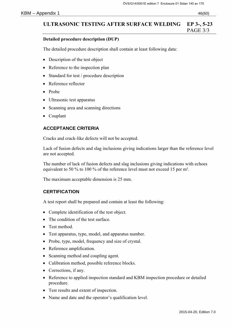
KBM – Appendix 1 46(60)
2015-04-20, Edition 7.0
ULTRASONIC TESTING AFTER SURFACE WELDING EP 3-, 5-23 PAGE 3/3
Detailed procedure description (DUP)
The detailed procedure description shall contain at least following data:
Description of the test object
Reference to the inspection plan
Standard for test / procedure description
Reference reflector
Probe
Ultrasonic test apparatus
Scanning area and scanning directions
Couplant
ACCEPTANCE CRITERIA
Cracks and crack-like defects will not be accepted.
Lack of fusion defects and slag inclusions giving indications larger than the reference level are not accepted.
The number of lack of fusion defects and slag inclusions giving indications with echoes equivalent to 50 % to 100 % of the reference level must not exceed 15 per m².
The maximum acceptable dimension is 25 mm.
CERTIFICATION
A test report shall be prepared and contain at least the following:
Complete identification of the test object.
The condition of the test surface.
Test method.
Test apparatus, type, model, and apparatus number.
Probe, type, model, frequency and size of crystal.
Reference amplification.
Scanning method and coupling agent.
Calibration method, possible reference blocks.
Corrections, if any.
Reference to applied inspection standard and KBM inspection procedure or detailed procedure.
Test results and extent of inspection.
Name and date and the operator’s qualification level.
ÖVS/G14/0001E edition 7 Enclosure 01 Sidan 140 av 170

KBM – Appendix 1 47(60)
2015-04-20, Edition 7.0
ULTRASONIC TESTING OF WELDED JOINTS DURING EP 3-, 5-24 MANUFACTURE AND INSTALLATION PAGE 1/2
APPLICATION
Ultrasonic testing to identify welding defects in full penetration butt welds, T-joints and corner joints in ferritic steels as an alternative for RT according to EP 3- 5-28.
The testing shall also include weld metal in buttering welds.
The testing shall be carried out after heat treatment and possible machining.
The testing of the fusion zone between the buttering weld and the base material may be carried out prior to other welding.
A detailed procedure for testing the weld joint in question shall be prepared by the supplier and approved by the purchaser.
SCOPE
Quality class 1 and 2:
All weld joints with a nominal wall thickness > 8 mm to be tested to full extent with regard to longitudinal or transversal defects.
Quality class 3-4:
Weld joints with a weld joint efficiency factor z > 0,85 shall be tested to full extent. The extent of testing in quality class 3 shall correspond to ASME III-ND and for class 4 valid AFS. The extent for austenitic stainless material and carbon steel is normally 10%. The distribution of random inspection is defined in chapter 2.1.5.2 (For class 4 ic C normally a visual inspection according to EP 3/5-13 is sufficient). If such defects are found that causes rejection of the welding, the extent of the testing to be extended as per chapter 2.1.5.3.
ÖVS/G14/0001E edition 7 Enclosure 01 Sidan 141 av 170

KBM – Appendix 1 48(60)
2015-04-20, Edition 7.0
ULTRASONIC TESTING OF WELDED JOINTS DURING EP 3-, 5-24 MANUFACTURE AND INSTALLATION PAGE 2/2
TEST REQUIREMENTS
The testing shall be carried out according to approved procedure meeting the requirements in section SS-EN ISO17640 level B, SS-EN ISO 22825 or corresponding requirements in equivalent foreign standard.
Detailed procedure description (DUP)
The detailed procedure shall contain at least the following data.
Description of the test object
Reference to the inspection plan
Standard for test / procedure description
Reference reflector
Probe
Ultrasonic test apparatus
Scanning area and scanning directions
Couplant
Acceptance criteria
ACCEPTANCE CRITERIA
Acceptance level 2 according to SS-EN ISO 11666.
CERTIFICATION
The test report shall be prepared and contain at least the information according to SS-EN ISO17640 chapter 13.
ÖVS/G14/0001E edition 7 Enclosure 01 Sidan 142 av 170

KBM – Appendix 1 49(60)
2015-04-20, Edition 7.0
RADIOGRAPHIC TESTING FOR PRODUCTION EP 2-27 OF CASTINGS PAGE 1/2
APPLICATION
Testing concerning internal discontinuities in parts of equipment made of steel and aluminium casting and nodular iron.
Testing shall be performed after finished forming and heat treatment. If appropriate, for production or test reasons, the testing can be performed at an earlier stage on the following conditions:
that the thickness of the material at the test occasion may exceed the final thickness with a maximum of 20% if it is less than 150 mm.
if the final thickness is larger than 150 mm, the thickness at the test occasion must not exceed the final with more than 10%.
evaluation of the result shall regardless of the thickness at the test occasion be made against the standard valid for final thickness according to table 5.
required supplementary testing will be made after final forming and heat treatment.
SCOPE
Quality class 1-2:
All castings shall be tested to the extent specified in ASME III, sub-paragraphs NB-2575.2 and NC-2575.2, respectively.
The film coverage shall be shown as a film map.
Quality class 3-4:
Highly stressed parts shall be tested. ASME III, paragraph ND-2571 is valid for design according to ASME.
Weld ends for pipe connections for equipment in quality class 3 shall be tested. The film coverage shall be shown as a film map.
For quality class 4 the extent according to applicable AFS is valid.
TEST REQUIREMENTS
Testing shall be carried out according to SS-EN 12681 class A.
Image quality according to SS-EN ISO 19232-3 class A.
Radiograms shall be interpreted according to SS-EN 25580.
If corresponding equivalent foreign standards for testing and interpretation are desired to be used, these to be approved by the purchaser.
ÖVS/G14/0001E edition 7 Enclosure 01 Sidan 143 av 170

KBM – Appendix 1 50(60)
2015-04-20, Edition 7.0
RADIOGRAPHIC TESTING FOR PRODUCTION EP 2-27 OF CASTINGS PAGE 2/2
ACCEPTANCE CRITERIA
Depending on the final material thickness and the test object, the test shall be evaluated according to standards in table 5 subject to the following:
Defects in category D, E, F, and G will not be accepted.
Casting for equipment in quality class 1 with a thickness of less than 25 mm must meet the requirements according to "Severity Level 1".
Weld ends of casting for equipment of in quality class 1-3 must meet the requirements according to "Severity Level 1" provided the material is of even thickness, from the final joint surface up to a distance of 20 mm.
Other castings shall fulfil the requirements of "Severity Level 2". However "Severity Level 3" can be applied for gas bubbles and non-metallic inclusions.
CERTIFICATION
A test report shall be prepared and contain at least the following data:
Complete identification of the test object and test area.
Dimensions and material of the test object.
Marking.
Test method and class.
Radiation source and exposure time.
Position of radiation source relative the test object, film, intensifying screens and filter, if any.
The films location on the test object – Film plan.
Image quality indicator and image quality.
Phase of production.
Reference to applied inspection standard and KBM inspection procedure or detailed procedure.
Test results.
Name, date and qualification level of the operator and the radiograph interpreter
Standard Thickness, t in mm
ASTM E 446 t < 50
ASTM E 186 50 < t < 115
ASTM E 280 t > 115
ASTM E 155 Aluminium
ASTM E 689 Nodular-iron
Table 5 Standards for evaluation of radiograms
ÖVS/G14/0001E edition 7 Enclosure 01 Sidan 144 av 170

KBM – Appendix 1 51(60)
2015-04-20, Edition 7.0
RADIOGRAPHIC TESTING OF WELDED JOINTS EP 3-, 5-28 DURING MANUFACTURE AND INSTALLATION PAGE 1/2
APPLICATION
Testing to detect defects in penetrating butt welds and corner joints as well as in weld deposit in buttering welds
The testing shall be carried out after finished forming, heat treatment and possible machining.
SCOPE
Quality class 1 and 2:
All welded joints shall be completely tested.
Quality class 3-4:
Weld joints with a weld joint efficiency factor z > 0,85 shall be tested to full extent. The extent of testing for quality class 3 shall follow ASME III-ND and for class 4 valid AFS. The extent for austenitic stainless materials and carbon steel is normally 10%. The distribution of random inspection is described in chapter 2.1.5.2. (For class 4 ic C normally a visual inspection according to EP 3/5-13 is sufficient)
Corner welds:
Interpretation of the extent of 100% radiographic test of corner welds between nozzles and branches on pipes and components.
OD = Nominal outside diameter in mm for nozzle or branch at connection to pipe or component.
OD 125 In agreement with the purchaser and the Accredited Laboratory, placement of films can be performed with partial coverage (e.g. 4 exposures equally distributed at 90 around the circumference). In addition, internal and external surface crack testing shall be performed. The agreed testing shall be specified in the detailed inspection plan.
70 OD 125 As a minimum one film, the purchaser and the Accredited Laboratory shall decide extent and location. In addition, internal and external surface crack tests shall be performed. The agreed testing shall be specified in the detailed inspection plan.
ÖVS/G14/0001E edition 7 Enclosure 01 Sidan 145 av 170
KBM – Appendix 1 52(60)
2015-04-20, Edition 7.0
RADIOGRAPHIC TESTING HAVE WELDED JOINTS EP 3-, 5-28 DURING MANUFACTURE AND INSTALLATION PAGE 2/2 If any such defect is found which render the welding unacceptable, the testing shall be extended as per chapter 2.1.5.3.
TEST REQUIREMENTS
Testing shall be carried out according to an approved procedure meeting the requirements of SS-EN ISO 17636-1 class B.
If corresponding equivalent foreign standards for testing and interpretation are desired to be used, these to be approved by the purchaser.
ACCEPTANCE CRITERIA
Acceptance level 1 according to SS-EN ISO 10675-1.
CERTIFICATION
The test report shall be prepared and contain at least the information according to SS-EN ISO 17636-1.
ÖVS/G14/0001E edition 7 Enclosure 01 Sidan 146 av 170

KBM – Appendix 1 53(60)
2015-04-20, Edition 7.0
VISUAL TESTING OF MATERIAL AND WELDS EP 2-, 3-, 5-29 PAGE 1/1
APPLICATION
As an alternative to PT and MT according to EP 2-, 3-, 5-16 respective -17 testing with visual technique, VT, may be used.
Personnel performing VT according to this examination procedure shall be qualified as per SS-EN ISO 9712 level 2.
SCOPE
See EP 2-, 3-, 5-16 respective -17.
TEST REQUIREMENTS
The test shall be performed according to:
SS-EN ISO 17637 Within this standard the special developed procedure for in-service inspections may be used:
P2VT190306-RAM-VT1l, Edition 1, Revision 11 ”General Procedure for Moulding VT of Surface Breaking Defects in Metallic Materials, Detection, Characterisation and Length Sizing of Defects”
A detailed test procedure alternatively a Technique sheet shall be prepared and reviewed.
ACCEPTANCE CRITERIA
According to the detailed test procedure. The acceptance level shall correspond to the one for MT according to EP 2-, 3-, 5-17.
CERTIFICATION
A test certificate shall be prepared according to the requirements in the detailed test procedure and at least contain the information corresponding to the requirements in EP 2-, 3-, 5-17.
ÖVS/G14/0001E edition 7 Enclosure 01 Sidan 147 av 170

KBM – Appendix 1 54(60)
2015-04-20, Edition 7.0
BENDING OF PIPES EP 3-, 5-43 PAGE 1/1
APPLICATION
Inspection of cold bending of pipes including inspection of the equipment used, performed through test bending. Cold bending shall be performed in compliance with a procedure that is prepared by the manufacturer and approved by the purchaser. The procedure shall fulfil the requirements in TBM section “Forming and straightening”.
SCOPE
At a minimum one test prior to installation, thereafter tests under the installation phase on random basis.
ACCEPTANCE CRITERIA
According to the purchaser approved procedure.
Cold formed sections shall in quality class 1-2 be examined by liquid penetrant- or magnetic particle test, as per extent specified in KBM EP X-16/17.
CERTIFICATION
The certificate that shall be prepared by the manufacturer, shall at least state/contain the following data:
Inspected parts/extent
Procedure applied
Results and conclusions
Date and name of the inspector
If a surface crack test (PT or MT) is performed, the result is to be reported in a separate report attached to the certificate for the inspected bend.
ÖVS/G14/0001E edition 7 Enclosure 01 Sidan 148 av 170

KBM – Appendix 1 55(60)
2015-04-20, Edition 7.0
INSTALLATION OF PIPE COUPLINGS EP 3-, 5-48 PAGE 1/1
APPLICATION
Visual inspection of installation of couplings furnished with cutting / compression ring.
SCOPE
Inspection shall be carried out to verify.
That the prescribed approved installation procedure or instruction has been followed.
The qualifications of the installation staff.
ACCEPTANCE CRITERIA
Couplings shall be installed according to installation procedures or instructions approved by the purchaser.
CERTIFICATION
Performed inspections shall be documented in the form of an inspection report.
ÖVS/G14/0001E edition 7 Enclosure 01 Sidan 149 av 170

KBM – Appendix 1 56(60)
2015-04-20, Edition 7.0
OPERATION TEST EP 6-50 PAGE 1/1
APPLICATION
Operation tests with regard to pressure vessel safety shall be executed at installations of new system part or after operations affecting or possibly affecting a system function.
SCOPE
After installation the licensee shall perform operation tests to check that safety equipment functions as intended and to make sure the system or equipment works satisfactory.
At the operation test the following shall be inspected:
The function of pipe supports and fix points and their interaction due to thermal expansion,
Vibrations in the system,
Tightness of the system or equipment,
Pressure relief,
Functions of other equipment of important for the pressure vessel safety,
that interlockings of importance for the pressure vessel safety are properly adjusted.
Safety valves or other safety equipment and snubbers can be tested in bench if the conditions to perform a full scale operation test are missing.
ACCEPTANCE CRITERIA
The function must correspond with drawings and specifications. Safety equipment shall meet the requirements in instructions and test procedures.
CERTIFICATION
Operating tests shall be documented by the licensee and be supervised by an Accredited Inspection Body in quality class 1-3, 4A and 4 inspection class A-B.
ÖVS/G14/0001E edition 7 Enclosure 01 Sidan 150 av 170

KBM – Appendix 1 57(60)
2015-04-20, Edition 7.0
INPECTION OF INSTALLATION EP 6-60 PAGE 1/1
APPLICATION
Inspection of the installation (final inspection) with regard to pressure vessel safety shall be performed at the installation of a new system part or if action is performed that can have an influence on the function of the system.
SCOPE
After installation or repair the licensee shall perform an inspection to ensure that the equipment is installed or repaired in accordance with approved documents.
The following shall be verified at the inspection:
that the installation of the equipment is in compliance with approved drawings and valid system flow sheets or concept to a new system flow sheet,
that the equipment has a permanent identification marking that can be tied to the documentation,
that safety equipment has been function tested and proved to function satisfactory,
that interlocks essential for the safety are correctly set,
that the installation or repair is finally judged to satisfy safety related requirements.
ACCEPTANCE CRITERIA
The installation shall comply with drawings and specifications, the installation shall also be confirmed to satisfy safety related requirements. Safety related equipment shall fulfil requirements and test procedures.
CERTIFICATION
The licensee shall document the inspection.
At inspection of equipment in quality class 1-3, 4A and 4 with inspection class A-B, the inspection shall be performed under supervision of Accredited Inspection Body.
ÖVS/G14/0001E edition 7 Enclosure 01 Sidan 151 av 170

KBM – Appendix 1 58(60)
2015-04-20, Edition 7.0
REVIEW OF FINAL QUALITY CONTROL EP 190 DOCUMENTATION PAGE 1/1
APPLICATION
The review of the final quality control documentation shall verify that the prescribed inspection and testing is carried out according to the detailed inspection plan, with approved results.
SCOPE
All certificates and records required according to the detailed inspection plan.
ACCEPTANCE CRITERIA
In case the supplier prepares the inspection record, his own review of the quality control documentation shall always have been performed with approved result, prior to the purchaser’s review.
CERTIFICATION
Up dated document index to be included in the final quality control documentation.
The final quality control documentation shall be organised with the applicable inspection plan as an index.
The quality control documentation shall include all certificates and records according to the requirements of the detailed inspection plan. The certificates shall be identified towards the inspection plan and the relevant detail.
Certificates and records shall verify that all requirements are fulfilled according to the detailed inspection plan.
Certificates and records shall be signed according to the requirements of the respective KBM Inspection Procedure.
Deviations shall be reviewed and the decision of required corrective action shall be issued by an authorised organisation. The corrective action shall be completed, inspected, documented and approved by the authorised organisation.
The delivery must not be released if there are open deviations or if the quality control documentation is rejected. Exemptions are only allowed with the purchaser’s written permission.
Certificate to be issued that verifies that the final quality control documention is reviwed and approved by the authorised organisation.
The certificate shall be included in the final quality control documentation.
ÖVS/G14/0001E edition 7 Enclosure 01 Sidan 152 av 170

KBM – Appendix 1 59(60)
2015-04-20, Edition 7.0
COLD BENDING OF HEAT EXCHANGER TUBES EP 286 PAGE 1/1
APPLICATION
Before starting the manufacturing the procedures for bending and cleaning of heat exchanger tubes must be qualified. Procedure qualification shall be carried out on tubes from the lot that is to be used for the manufacturing. The bending procedure must be identical with the procedure used at manufacturing.
After bending, the tubes must be cleaned according to the cleaning procedure, which applies to the manufacturing.
The cleaned tubes shall be cut up in small test samples, the bent portions shall be included in the test sample. The test samples shall be inspected concerning cleanliness, surface finish and dimensions.
SCOPE
The testing shall comprise at least 5 test samples of the smallest radius to be used.
ACCEPTANCE CRITERIA
According to the purchaser’s approved procedure.
CERTIFICATION
A certificate prepared by the manufacturer shall state:
Date of inspection
Used procedure
Result
Material certificate and identity of test samples
ÖVS/G14/0001E edition 7 Enclosure 01 Sidan 153 av 170

KBM – Appendix 1 60(60)
2015-04-20, Edition 7.0
INSPECTION OF REPAIRS IN WELDS AND CASTINGS EP 376 PAGE 1/1
APPLICATION
Visual and dimensional inspection and non-destructive testing of weld repairs in conjunction with manufacturing and installation. For castings shall only repairs performed after heat treatment be inspected as per this examination procedure.
REMOVAL OF DEFECTS BY FOR INSTANCE GRINDING
Inspection of the dimension of remaining material thickness of the weld/casting and visual inspection of ground surface according to KBM EP X-13.
Penetrant or magnetic particle inspection of the surface according to KBM EP X-16/17.
REPAIR BY WELDING
Before the weld repair can be started, the manufacturer to prepare a repair procedure. The procedure shall be reviewed and approved by the purchaser.
Prior to the welding, a visual inspection and possible non-destructive testing shall have been carried out.
Prior to the weld repair, the prescribed conditions for the repair shall be verified.
Visual and dimensional inspection as well as the non-destructive testing, prescribed for the original weld/casting shall be repeated for the repaired weld area.
SCOPE
All repairs of unacceptable defects in welds/castings.
TEST REQUIREMENTS
According to the original requirements for the weld/casting.
ACCEPTANCE CRITERIA
All requirements in TBM concerning repairs shall be fulfilled. After the repair, the original acceptance criteria for the weld/casting shall be fulfilled.
CERTIFICATION
The manufacturer shall document all weld repairs and the inspector must verify the data. The documentation must comprise:
Reason for rejection with reference to existing test records Size, depth and location of defect Repair procedure Inspection reports Other reports required by the inspection plan for the original weld/casting
ÖVS/G14/0001E edition 7 Enclosure 01 Sidan 154 av 170

KBM – Appendix 2 1(16)
2015-04-20, Edition 7.0
APPENDIX 2
DESCRIPTION OF INSPECTION PROCEDURES (OTHER INSPECTION)
ÖVS/G14/0001E edition 7 Enclosure 01 Sidan 155 av 170

KBM – Appendix 2 2(16)
2015-04-20, Edition 7.0
INSPECTION OF CLEANLINESS EP 425 PAGE 1/1
APPLICATION
Inspection of the surfaces of the units ready for delivery or receipt inspection is performed through visual inspection of the surfaces.
At final inspection shall the inspection be performed as per procedures prepared by the manufacturer and approved by the purchaser, or as per the respective licensee’s instructions/guidelines for clean system. (Foreign material exclusion – FME).
SCOPE
All surfaces.
ACCEPTANCE CRITERIA
The cleanliness of the finalised components shall meet the following requirements and/or equivalent requirements stated in the manufacturer's specifications and approved by the purchaser. Alternatively, as per the respective licensee’s instructions/guidelines for clean system
Weld Surfaces: Stainless weld surfaces in components for systems for process water shall fulfil the purchaser’s oxide reference No. 17. Oxide reference No. 18 can as exception be approved by the purchaser in cases where there is no risk of corrosion damages. See TBM attachment 4.
CERTIFICATION
Certificates shall be issued by the manufacturer and be verified by the inspector. The certificate shall state:
Date of the inspection
Detail inspected
Methods used for the inspection
Inspection results
ÖVS/G14/0001E edition 7 Enclosure 01 Sidan 156 av 170

KBM – Appendix 2 3(16)
2015-04-20, Edition 7.0
INSPECTION OF CORROSION PROTECTION EP 430 PAGE 1/1
APPLICATION
All surfaces shall be visually inspected with suitable equipment, this shall be performed prior to as well as after application of prescribed corrosion protection/surface treatment.
SCOPE
All surfaces where corrosion protection/surface treatment is requested in purchase order, manufacturing specification and deliveryspecification, drawing etc.
ACCEPTANCE CRITERIA
As per the purchaser’s specification or according to specification prepared by the manufacturer and approved by the purchaser.
CERTIFICATION
The performed inspection shall bedocumented and reported by the manufacturer in a report containing as a minimum the following:
Date of inspection
Inspected component
Specification for surface treatment
Result of inspection
Signature by inspector
ÖVS/G14/0001E edition 7 Enclosure 01 Sidan 157 av 170

KBM – Appendix 2 4(16)
2015-04-20, Edition 7.0
INSPECTION OF PACKING AND PRESERVATION EP 435 PAGE 1/1
APPLICATION
Visual inspection of component packing and preservation when required by the purchaser.
SCOPE
Random inspection in connection with packing and preservation.
ACCEPTANCE CRITERIA
Compliance with the regulation under the heading "Transport" in current TBM or with specification prepared by the supplier approved by the purchaser.
CERTIFICATION
A certificate shall be issued by the manufacturer and be verified by the inspector with data of the inspected component, the results and the date of the inspection.
ÖVS/G14/0001E edition 7 Enclosure 01 Sidan 158 av 170

KBM – Appendix 2 5(16)
2015-04-20, Edition 7.0
TIGHTNESS TESTING – CHECK VALVES EP 441 AND ISOLATION VALVES PAGE 1/1
APPLICATION
Tightness testing of closing devices.
The valves must not be exposed to abnormal bending or compressive stresses during the test.
When testing isolation valves, the pressure must be applied on the correct side of the closing device according to instructions in the valve specification. Valves equipped with actuators shall be tested as complete units on the purchaser's explicit demand. Testing shall be performed and meet the requirements as per SS-EN 12266-1 or according to the procedure prepared by the manufacturer and approved by the purchaser.
Valve to be used as isolation valve shall in addition be tightness tested at the test pressure required in 10CFR50 Appendix J Type C-test.
SCOPE
All check and isolation valves where prescribed according to the detailed inspection plan.
TEST REQUIREMENTS
According to SS-EN 12266-1.
The air used as pressure medium shall be clean and dry.
The cleanliness before testing, water quality for testing (if water is used) and treatment after testing shall meet the requirements of the purchaser.
ACCEPTANCE CRITERIA
Leakage rate A according to SS-EN 12266-1, unless else specified by the purchaser.
CERTIFICATION
Certificates shall be issued by the manufacturer and be verified by the inspector. The certificate shall state:
Procedure/standard
Test method
Test pressure and holding time
Test result
Date of testing
ÖVS/G14/0001E edition 7 Enclosure 01 Sidan 159 av 170

KBM – Appendix 2 6(16)
2015-04-20, Edition 7.0
TIGHTNESS TESTING – CONTROL VALVES EP 442 WITH NO CLOSING FUNCTION PAGE 1/1
APPLICATION
Inspection of seat leakage
The test shall be made with water at room temperature. Normal operating data for the actuator must not be exceeded during the test.
Test pressure: Specified pressure upstream and atmospheric pressure downstream the unit.
SCOPE
All control valves where prescribed in the detailed inspection plan.
TEST CRITERIA
As per SS-EN 60534-4.
ACCEPTANCE CRITERIA
As per SS-EN 60534-4 Leakage class I (or according to agreement between the purchaser and the manufacturer)
Cleanliness before testing, water quality during testing and treatment after testing shall meet the requirements of the purchaser.
CERTIFICATION
Certificates shall be issued by the manufacturer and be verified by the inspector. The certificate shall state:
Procedure/standard
Test method
Test pressure and holding time
Test result
Date of testing
ÖVS/G14/0001E edition 7 Enclosure 01 Sidan 160 av 170

KBM – Appendix 2 7(16)
2015-04-20, Edition 7.0
TIGHTNESS TESTING – SAFETY VALVES FOR EP 443 LIQUIDS PAGE 1/1
APPLICATION
Inspection of tightness of the sealing device
Safety valves in liquid born systems shall be tested for tightness according to below, or according to the procedure prepared by the manufacturer and approved by the purchaser.
Testing with water
Testing shall be carried out with water to which a wetting agent has been added.
1. Increase the pressure to 0,1 MPa below the opening pressure.
2. Lower the pressure to operating pressure.
3. When conditions have become stable, the leakage shall be measured for one hour.
4. Inspection and and if needed adjustment of the opening pressure.
5. Lower the pressure to operating pressure.
6. Measure the leakage for 15 minutes when stable conditions are reached.
SCOPE
All safety valves when prescribed in the detailed inspection plan.
ACCEPTANCE CRITERIA
Tightness requirements to be specified by the purchaser.
Cleanliness before testing, water quality for testing and treatment after testing shall meet the requirements of the purchaser.
CERTIFICATION
Certificates shall be issued by the manufacturer and be verified by the inspector. The certificate shall state:
Procedure/standard
Test method
Test pressure and holding time
Test result
Date of testing
ÖVS/G14/0001E edition 7 Enclosure 01 Sidan 161 av 170

KBM – Appendix 2 8(16)
2015-04-20, Edition 7.0
TIGHTNESS TESTING – SAFETY VALVES EP 444 FOR STEAM OR AIR PAGE 1/1
APPLICATION
Inspection of the sealing device tightness
Safety valves for steam, air or other gaseous media shall be tested for tightness according to requirements below or according to a procedure prepared by the manufacturer and approved by the purchaser.
Testing with air
As per applicable purchaser valve specification, or as per specification prepared by the manufacturer and approved by the purchaser. E.g. as per SS-EN ISO 4126-1.
SCOPE
All safety valves for steam air or other gas.
ACCEPTANCE CRITERIA
According to SS-EN ISO 4126-1.
CERTIFICATION
Certificates shall be issued by the manufacturer and be verified by the inspector. The certificate shall state:
Procedure/standard
Test method
Test pressure and holding time
Test result
Date of testing
ÖVS/G14/0001E edition 7 Enclosure 01 Sidan 162 av 170

KBM – Appendix 2 9(16)
2015-04-20, Edition 7.0
FUNCTIONAL TESTING – CHECK VALVES EP 451 AND ISOLATING VALVES PAGE 1/1
APPLICATION
In compliance with the purchaser's specification or the specification prepared by the manufacturer and approved by the purchaser.
SCOPE
As prescribed in the detailed inspection plan.
TEST REQUIREMENTS
Cleanliness before testing, test water quality (if water is used) and treatment after testing shall meet the requirements of the purchaser.
ACCEPTANCE CRITERIA
In compliance with actual specification from the purchaser or the specification prepared by the manufacturer and approved by the purchaser.
CERTIFICATION
A certificate with the results from the functional test and reference to applied specifications/standards shall be issued by the manufacturer and be verified by the inspector.
ÖVS/G14/0001E edition 7 Enclosure 01 Sidan 163 av 170

KBM – Appendix 2 10(16)
2015-04-20, Edition 7.0
FUNCTIONAL TESTING – SAFETY VALVES EP 453 PAGE 1/1
APPLICATION
In compliance with the purchaser’s specification or the specification prepared by the manufacturer and approved by the purchaser.
SCOPE
All safety valves where prescribed according to detailed inspection plan.
TEST REQUIREMENTS
The test equipment for each respective pressure range to be equiped with calibrated pressure gauges satisfying class 0,6 as per standard SMS 1554, or similar requirements of foreign standard. The test equipment is to be furnished with a control valve.
Cleanliness before testing, test water quality (if water is used) and treatment after testing shall meet the requirements of the purchaser.
ACCEPTANCE CRITERIA
In compliance with actual specification from the purchaser or the specification prepared by the manufacturer and approved by the purchaser. Requirements of ISO 4126 shall be fulfilled.
CERTIFICATION
Certificates shall be issued by the manufacturer and be verified by the inspector. The certificate shall state:
Measured opening pressure
Measured pressure increase in %
Measured blow down in %
Reference to prevailing specification or standard
Date of testing
ÖVS/G14/0001E edition 7 Enclosure 01 Sidan 164 av 170

KBM – Appendix 2 11(16)
2015-04-20, Edition 7.0
FUNCTIONAL TESTING – CENTRIFUGAL PUMPS EP 454 PAGE 1/1
APPLICATION
The testing shall be performed as per SS-EN ISO 9906 or according to other manufacturer specification approved by the purchaser.
SCOPE
All centrifugal pumps where test is required by the purchase order or the detailed inspection plan.
TEST REQUIREMENTS
Hyraulic test requirements are specified in SS-EN ISO 9906. Scope and grade of measuring accuracy according to agreement between purchaser and manufacturer. Cleanliness before testing, water quality for testing and the treatment after testing shall meet the requirements of the purchaser.
ACCEPTANCE CRITERIA
As per SS-EN ISO 9906, grade of measuring accuracy according to grade 2 unless otherwise agreed between purchaser and manufacturer. All pump data given in the purchaser's pump specification must fall within the limits of tolerance limits stated in the specification or in the agreed test procedure.
CERTIFICATION
Certificate with the results of the function tests according to the pump specification/test procedure.
ÖVS/G14/0001E edition 7 Enclosure 01 Sidan 165 av 170

KBM – Appendix 2 12(16)
2015-04-20, Edition 7.0
FUNCTIONAL TESTING – DISPLACEMENT PUMPS EP 457 PAGE 1/1
APPLICATION
Testing shall be carried out according to SS-EN 14343 or other standard specified by the manufacturer and approved by the purchaser.
SCOPE
All displacement pumps where test is prescribed in the purchase order or the detailed inspection plan.
TEST REQUIREMENTS
As per SS-EN 14343. Scope and grade of measuring accuracy according to agreement between purchaser and manufacturer. Cleanliness before testing, water quality for testing and the treatment after testing shall meet the requirements of the purchaser.
ACCEPTANCE CRITERIA
As per SS-EN 14343, acceptance level according to class 2 unless otherwise agreed between purchaser and manufacturer. The pump data given in the purchaser's pump specification shall be within the tolerance limits of the specification or agreed test procedure.
CERTIFICATION
A certificate with the results of the function tests according to the pump specification / test procedure.
ÖVS/G14/0001E edition 7 Enclosure 01 Sidan 166 av 170

KBM – Appendix 2 13(16)
2015-04-20, Edition 7.0
FUNCTIONAL TESTING – SNUBBERS EP 458 PAGE 1/1
APPLICATION
Testing shall be carried out in accordance with manufacturer specification that has been approved by the purchaser.
The testing shall be performed in test bench.
SCOPE
All snubbers in all quality classes.
Inspection of:
Friction
Length of stroke
Blocking speed
Dynamic test
TEST REQUIREMENTS
In accordance with manufacturer specification that has been approved by the purchaser.
ACCEPTANCE CRITERIA
The function shall comply with with manufacturer specification that has been approved by the purchaser.
CERTIFICATION
The Manufacturer shall issue a certificate with the results of the function test and reference to used specification/standard.
ÖVS/G14/0001E edition 7 Enclosure 01 Sidan 167 av 170

KBM – Appendix 2 14(16)
2015-04-20, Edition 7.0
“STRIP TEST” – PUMPS EP 486 PAGE 1/1
APPLICATION
The test shall be performed in compliance with the specification prepared by the manufacturer and approved by the purchaser.
SCOPE
Inspection of:
All bearings
Shafts
Impellers
Wear surfaces
Stator (wet pump-motor units)
Rotor (wet pump-motor units)
Coupling
Mechanical seal, stuffing boxe and glands
Static seal
Diffuser
Sealing surfaces, gaskets and O-rings
ACCEPTANCE CRITERIA
All pump data stated in the purchaser’s pump specification, shall be within the tolerance limits stated in the specification or in agreed test procedure.
CERTIFICATION
Certificate with the results from the tests according to the pump specification / test procedure.
ÖVS/G14/0001E edition 7 Enclosure 01 Sidan 168 av 170

KBM – Appendix 2 15(16)
2015-04-20, Edition 7.0
BALANCING EP 490 PAGE 1/1
APPLICATION
Balancing shall be carried out according to SS-ISO 1940-1, or to other standard specified by the manufacturer and approved by the purchaser.
SCOPE
All rotating parts as prescribed in the detailed inspection plan.
ACCEPTANCE CRITERIA
According to the purchaser’s requirements, or according to the standard/procedure used by the manufacturer, approved by the purchaser.
CERTIFICATION
Certificate with the results of the inspection, according to the pump specification / test procedure.
ÖVS/G14/0001E edition 7 Enclosure 01 Sidan 169 av 170

KBM – Appendix 2 16(16)
2015-04-20, Edition 7.0
INSPECTION OF SYSTEM CLEANLINESS EP 560 PAGE 1/1
APPLICATION
Prior to taking installed systems into operation, they shall be vacuum cleaned, blown/flushed with air and/or water according to the applicable instruction for each system. The result shall be checked in the discharge by:
inspection of the quantity of mechanical impurities by filtering
measuring the electric conductivity
Inspection during installation shall be performed as per the respective licensee’s instructions/guidelines for clean system. (Foreign Material Exclusion – FME).
SCOPE
All systems stated in a detailed instruction, or otherwise as prescribed in the detailed inspection plan.
ACCEPTANCE CRITERIA
According to the respective licensee’s instructions/guidelines for clean system.
CERTIFICATION
Certificate shall be issued by the manufacturer and be signed by the responsible individual, stating at least:
Date of of flushing
System flushed
Valid procedure
Whether totally demineralised water has been used or not
Possible additives to the water used for flushing
Where, when and how the analysed samples were selected
Conductivity and temperature of the sample
Solid particles at filtering
ÖVS/G14/0001E edition 7 Enclosure 01 Sidan 170 av 170