quality of service enhancement for drive-thru internet
TRANSCRIPT

Quality of Service Enhancement
for Drive-thru Internet
by
Qing Shen
Bachelor of Communications Engineering,Xidian University, China, 2010
A Thesis Submitted in Partial Fulfilment of the Requirements forthe Degree of
Master of Computer Science
in the Graduate Academic Unit of Computer Science
Supervisor(s): Wei Song, Ph.D., Faculty of Computer ScienceWeichang Du, Ph.D., Faculty of Computer Science
Examining Board: Virendra Bhavsar, Ph.D., Faculty of Computer Science, ChairJohn M. DeDourek, Master of Science, Faculty of Computer ScienceDonglei Du, Ph.D., Faculty of Business Administration
This thesis is accepted by the
Dean of Graduate Studies
THE UNIVERSITY OF NEW BRUNSWICK
October, 2014
c⃝Qing Shen, 2015

Abstract
Drive-thru Internet is a promising technique that exploits the inter-connected
roadside access points (APs) to offer Internet access. Although there have
been many studies aiming to improve the performance of the drive-thru In-
ternet system, most existing solutions cannot support multiple services (e.g.,
data, video, and voice) and guarantee their quality of service (QoS) require-
ments simultaneously. This thesis presents QoS enhancement solutions for
drive-thru Internet to enhance the access performance of different applica-
tions. We firstly propose an opportunistic vehicle-to-vehicle relay protocol
with adaptive modulation to address the relay selection problem of drive-
thru Internet. Then, an adaptive collision avoidance with service differenti-
ation scheme is presented to improve the overall network performance with
dynamically adjusted medium access control (MAC) layer parameters and
support multiple services by assigning an appropriate priority level for each
specific packet. We also designed and developed a simulator for comparing
and evaluating different QoS schemes in a drive-thru network environment.
ii

Acknowledgements
I wish to gratefully acknowledge the following people for their help and
support during my study at UNB.
Foremost, I would like to give the sincere gratitude to my two supervisors
Dr. Wei Song and Dr. Weichang Du. They devoted a large amount of
time, guiding me through the research field with great patience and detailed
suggestions.
I want to thank my fellows Dizhi Zhou, Peijian Ju, Xiaojing Li, A-long Jin,
and Kai Dong for discussing my questions and offering constructive advice.
I am grateful to all staffs of the Faculty of Computer Science for building
such a nice environment and offering relevant resources for my study and
research. I would like to thank my friends for their company and assistance
in my daily life.
A special appreciation is given to committee members Professor John De-
dourek, Professor Virendra Bhavsar, and Professor Donglei Du. Their com-
ments are important for my thesis.
Last but not least, I would like to express my deep appreciation to my
iii

parents and my little sister for their love and support. Without them, I
would never have the chance to study in Canada and complete the Master’s
thesis.
iv

Table of Contents
Abstract ii
Acknowledgments iii
Table of Contents viii
List of Tables ix
List of Figures xi
Abbreviations xii
Symbols xv
1 Introduction 1
1.1 Motivation . . . . . . . . . . . . . . . . . . . . . . . . . . . . 1
1.2 Research Objectives . . . . . . . . . . . . . . . . . . . . . . . 3
1.2.1 QoS Enhancement Solutions . . . . . . . . . . . . . . 3
1.2.2 Simulator for Evaluation and Comparison . . . . . . 4
1.3 Thesis Organization . . . . . . . . . . . . . . . . . . . . . . . 5
v

2 Background and Related Works 6
2.1 Vehicular Networks . . . . . . . . . . . . . . . . . . . . . . . 6
2.1.1 Vehicle Mobility . . . . . . . . . . . . . . . . . . . . . 6
2.1.2 Protocol Stack of Vehicular Ad-hoc Networks (VANETs) 12
2.1.3 Connectivity of VANETs . . . . . . . . . . . . . . . . 15
2.2 Related Works . . . . . . . . . . . . . . . . . . . . . . . . . . 17
3 Opportunistic Vehicle Relay with Adaptive Modulation 21
3.1 Relay Selection Problem . . . . . . . . . . . . . . . . . . . . 21
3.2 System Model . . . . . . . . . . . . . . . . . . . . . . . . . . 23
3.3 Analysis of Proposed Scheme . . . . . . . . . . . . . . . . . 26
3.3.1 Statistics of Potential Relay Vehicles . . . . . . . . . 27
3.3.2 Packet Delay and Success Probability . . . . . . . . . 29
3.4 Discussion . . . . . . . . . . . . . . . . . . . . . . . . . . . . 32
4 Adaptive Collision Avoidance with Service Differentiation 34
4.1 MAC Layer Enhancement . . . . . . . . . . . . . . . . . . . 35
4.1.1 Adaptive MAC Layer Parameters . . . . . . . . . . . 35
4.1.2 Adaptive Contention Window Algorithm . . . . . . . 37
4.2 Multi-service Differentiation . . . . . . . . . . . . . . . . . . 38
4.2.1 Priority Assignment . . . . . . . . . . . . . . . . . . 38
4.2.2 RSU Internal Buffer Scheduling . . . . . . . . . . . . 44
4.3 Summary . . . . . . . . . . . . . . . . . . . . . . . . . . . . 44
5 Simulator Design and Implementation 46
vi

5.1 Simulation Scenario . . . . . . . . . . . . . . . . . . . . . . . 47
5.1.1 Network Topology . . . . . . . . . . . . . . . . . . . 47
5.1.2 IEEE 802.11p . . . . . . . . . . . . . . . . . . . . . . 48
5.1.3 Multiple Services . . . . . . . . . . . . . . . . . . . . 48
5.1.4 Vehicular Traffic Models . . . . . . . . . . . . . . . . 49
5.2 Simulator Framework . . . . . . . . . . . . . . . . . . . . . . 49
5.3 Traffic Model Simulator . . . . . . . . . . . . . . . . . . . . 52
5.4 Multi-service Simulator . . . . . . . . . . . . . . . . . . . . . 52
5.5 Event-driven MAC Layer Simulator . . . . . . . . . . . . . . 53
6 Experiment Results and Discussions 60
6.1 Validation of Theoretical Analysis . . . . . . . . . . . . . . . 61
6.1.1 Analysis Accuracy . . . . . . . . . . . . . . . . . . . 61
6.1.2 Effectiveness . . . . . . . . . . . . . . . . . . . . . . . 62
6.2 Simulation Settings . . . . . . . . . . . . . . . . . . . . . . . 65
6.3 Results of Opportunistic Relay with Adaptive Modulation . 67
6.4 Results of Adaptive Collision Avoidance with Service Differ-
entiation . . . . . . . . . . . . . . . . . . . . . . . . . . . . . 77
6.5 Results of Two Combined Schemes . . . . . . . . . . . . . . 83
7 Conclusion and Future Works 88
7.1 Conclusion . . . . . . . . . . . . . . . . . . . . . . . . . . . . 88
7.2 Future Works . . . . . . . . . . . . . . . . . . . . . . . . . . 90
Bibliography 95
vii

Vita
viii

List of Tables
4.1 Default parameters in IEEE 802.11p. . . . . . . . . . . . . . 40
4.2 Modified parameters for this study. . . . . . . . . . . . . . . 40
6.1 System parameters. . . . . . . . . . . . . . . . . . . . . . . . 61
6.2 The overall simulation parameters. . . . . . . . . . . . . . . 66
6.3 FTM traffic model parameters. . . . . . . . . . . . . . . . . 66
6.4 Description of traffic flows. . . . . . . . . . . . . . . . . . . . 66
ix

List of Figures
2.1 Relationships between the speed-flow, speed-density, and flow-
density [1]. . . . . . . . . . . . . . . . . . . . . . . . . . . . 8
2.2 DSRC channel designations in the U.S. [2]. . . . . . . . . . 12
2.3 Layered architecture for DSRC in the U.S. [2]. . . . . . . . 13
3.1 System model of drive-thru Internet access with V2V relay. . 24
5.1 Highway VANET topology (adapted from [3]). . . . . . . . 47
5.2 Simulator framework. . . . . . . . . . . . . . . . . . . . . . 50
5.3 Event-driven state transition for MAC layer simulator. . . 54
6.1 Analysis and simulation results of overall success probability
and average packet delay. . . . . . . . . . . . . . . . . . . . . 62
6.2 Variation of overall success probability and average packet
delay with modulation modes. . . . . . . . . . . . . . . . . . 63
6.3 Overall success probability and average packet delay with
modulations adapted with vehicle density. . . . . . . . . . . 64
6.4 The overall throughput in the uplink scenario. . . . . . . . . 69
6.5 The average throughput per vehicle in the uplink scenario. . 71
x

6.6 The average delay in the uplink scenario. . . . . . . . . . . . 72
6.7 The overall throughput in the multi-service scenario. . . . . 73
6.8 The average delay in the multi-service scenario. . . . . . . . 74
6.9 The average throughput per vehicle of different services in the
multi-service scenario. . . . . . . . . . . . . . . . . . . . . . 75
6.10 The average delay of different services in the multi-service
scenario. . . . . . . . . . . . . . . . . . . . . . . . . . . . . . 76
6.11 The overall throughput in the multi-service scenario. . . . . 79
6.12 The average delay in the multi-service scenario. . . . . . . . 80
6.13 The average throughput per vehicle of different services in the
multi-service scenario. . . . . . . . . . . . . . . . . . . . . . 81
6.14 The average delay of different services in the multi-service
scenario. . . . . . . . . . . . . . . . . . . . . . . . . . . . . . 82
6.15 The overall throughput in the multi-service scenario. . . . . 84
6.16 The average delay in the multi-service scenario. . . . . . . . 85
6.17 The average throughput of different services in the multi-
service scenario. . . . . . . . . . . . . . . . . . . . . . . . . . 86
6.18 The average delay of different services in the multi-service
scenario. . . . . . . . . . . . . . . . . . . . . . . . . . . . . . 87
xi

List of Abbreviations
3G The third generation cellular network
ACASD Adaptive collision avoidance with service differentiation
ACW Adaptive contention window
AIFS Arbitration inter-frame space
AP Access point
AC Application category
AWGN Additive white Gaussian noise
BBS Basic service set
BE Best effort traffic
BER Bit error rate
BK Background traffic
BPSK Binary phase-shift keying
CCH Control channel
CDF Cumulative distribution function
CSM Constant speed model
xii

CSMA/CA Carrier sense multiple access/collision avoidance
CW Contention window
DA Normal data traffic
DCF Distributed coordination function
DEA Distributed enhancement algorithm
DSRC Dedicated shor-range communication
EDCA Enhanced distributed channel access
FCC Federal communications commission
FTM Fluid traffic motion
IDM Intelligent driver model
IDM-LC Intelligent driver model with lane-changing
LEO Low earth orbit
MAC Medium access control
MEO Medium earth orbit
MI Monitor interval
M-QAM M-ary quadrature amplitude modulation
OCB Outside of the context of a basic service set
ORAM Opportunistic relay with adaptive modulation
OFDM Orthogonal frequency division multiplexing
OI Observation interval
PHY Physical layer
PPP Poissson point process
PW Priority weight
QoS Quality of service
RSU Roadside Unit
xiii

SCH Service channel
SNR Signal to noise ratio
V2I Vehicle to vehicle
V2V Vehicle to infrastructure
V2X Including both V2I and V2V
VANET Vehicular ad-hoc network
VI Video traffic
VO Voice traffic
VoIP Voice over Internet Protocol
VT Virtual transmission time
WAVE Wireless access in vehicular networks
WiMAX Worldwide interoperability for microwave access
xiv

List of Symbols
Bw Channel bandwidth (Hz)
D Tagged vehicle
Eb/N0 Ratio of bit energy to noise power intensity
F Maximum backoff time
Fγ CDF of γRD
gxy Path-loss effect
GP CDF of PRD
G̃P CDF of highest transmission success probability among relays
hxy Small-scale channel fading
hW PDF of the backoff time of the potential relay vehicles
HW CDF of the backoff time of the potential relay vehicles
Ic Probability of no collision among the relay vehicles
k k = log2 M , where M is the constellation size of modulation
K Number of the modulation modes
K/s Delay time units of the direct transmission from the RSU to vehicle
xv

K/v Delay time units of the relay transmission to vehicle
l Number of potential relays
L Distance between the RSU and vehicle
M Constellation size
Ms Constellation size of the modulation of the RSU
Mv Constellation size of the modulation of the vehilce
Nr Number of potential relays
Nt Power of additive white Gaussian noise (AWGN)
Pt Transmit power
Pt/Nt Transmit SNR at the RSU
PBPSK Bit error rates of BPSK
PQAM Bit error rates of M-QAM
PRD Transmission success probability from relay vehicle to destination
P̃RD Average transmission success probability of the best relay
Psuc Overall transmission success probability
PSD Success probability of the direct transmission
PSR Probability that a relay vehicle correctly overhears the packet
Pxy Probability of correctly decoding a packet from location x to y
R Relay vehicle
Rt Transmission rate (bps)
s Modulation mode of the RSU
T Average packet delay
W Backoff time
W Mean backoff time
α Path-loss exponent
xvi

β Threshold of the received SNR
βs Threshold of the received SNR from source to destination
γxy Signal-to-noise ratio (SNR) of the received signal
γRD Average received SNR from a potential relay to the destination
λ Vehicle density
Λ Intensity measure of these potential relays
xvii

Chapter 1
Introduction
1.1 Motivation
In recent years, there have been increasing research attention to utilize ex-
isting wireless technologies such as WiFi to provide Internet access to users
in moving vehicles, which is termed as drive-thru Internet [4]. Such systems
take advantage of inter-connected road-side access points (APs) to enable
network access to vehicular users by temporarily connecting to an AP as the
vehicle passes through the AP’s coverage area [5]. However, due to the chal-
lenges of the vehicular environment, the network connectivity is short-lived
and the Quality of Service (QoS) to vehicular users is not satisfactory.
There are several wireless access technologies available for vehicular commu-
nications, such as IEEE 802.11, the third generation (3G) cellular network,
and the Worldwide Interoperability for Microwave Access (WiMAX). IEEE
1

802.11 as a mature wireless technology has been widely investigated given
its advantages of high bandwidth and low cost. IEEE 802.11p [6], which
is an amendment of IEEE 802.11 standard, aims to provide more efficient
wireless access in a vehicular environment. However, vehicular environments
are more complex than common wireless environments due to their unique
features, such as constrained mobility pattern, high mobility of vehicles and
fast topology changes. Because of the mobility of vehicles, the radio link
between two neighbor vehicles is unreliable and the opportunity of access to
a road-side AP is fleeting.
Although one primary motivation for developing vehicular communication
technologies is to support safety applications, which are able to prevent
accidents, this thesis focuses on developing an efficient QoS enhancement
solution for drive-thru Internet. There are different QoS requirements for
diverse vehicular applications from best effort to guaranteed QoS require-
ments.
Due to the limited time and investment, it is often not feasible for researchers
to deploy a real testing environment and investigate the effects of different
schemes on QoS in the drive-thru Internet. To evaluate and demonstrate the
QoS performance of various schemes in the specific scenario, we also develop
a simulator for the drive-thru Internet.
2

1.2 Research Objectives
This thesis aims to develop efficient solutions to deliver packets of different
categories (e.g., data, video, and voice) with specific QoS guarantee in a
vehicular environment. However, there are many challenges to deal with
to achieve our goal. The vehicular environment imposes its unique charac-
teristics on the vehicular network. Besides the unstable wireless radio, the
unpredictable behavior of vehicles often makes the Vehicle-to-Vehicle (V2V)
and Vehicle-to-Infrastructure (V2I) link unavailable and unreliable. Due to
the limited budget, it is not possible to deploy enough APs to cover all
road segments, which results that the access to the Internet in the vehicu-
lar network is usually intermittent. If many users run different applications
simultaneously, the network congestion may occur and the delay would be
long. Thus, efficient QoS enhancement solutions need to be developed to
guarantee the user QoS requirements in the vehicular network.
1.2.1 QoS Enhancement Solutions
As the resources in a vehicular network are often limited (e.g., a limited num-
ber of APs and a small number hops), it is challenging to support IP-based
applications with QoS assurance. Some applications (e.g., voice, video) have
more stringent QoS requirements compared with other applications (e.g.,
data). Hence, it is important to incorporate service-aware QoS enhancement
strategies to satisfy the different QoS requirements of various applications.
3

Moreover, in a real network environment, different applications are often
run simultaneously by vehicle users. Hence, the QoS schemes should also
provide service differentiation (e.g., among data, video, voice) so that the
traffic subject to a strict QoS requirement can be prioritized.
1.2.2 Simulator for Evaluation and Comparison
In order to evaluate the performance of the QoS enhancement schemes, we
also design an appropriate simulator. Because the vehicle trace which reflects
the real movement of vehicles is necessary to validate the effectiveness of the
proposed schemes, a vehicle trace simulator is developed firstly. The vehicle
trace simulator should be able to produce a trace file according to different
vehicle mobility models given a set of parameters (e.g., road topology, vehicle
density, and vehicle speed range).
Due to the specific QoS requirements of different applications, a set of QoS
metrics related to the applications will also be selected when we compare
the performance of the QoS enhancement solutions with others. Our simula-
tor will simulate different QoS solutions and collect their performance with
respect to the specific QoS metrics. Thus, we can observe the strength and
weakness of different solutions in a variety of network scenarios.
4

1.3 Thesis Organization
The thesis contains seven chapters, and the remaining of the thesis is orga-
nized as follows. Chapter 2 introduces the background knowledge on vehicu-
lar networks and the related works we have reviewed. Chapter 3 introduces
the proposed opportunistic vehicle relay with adaptive modulation scheme.
Chapter 4 presents an algorithm which is able to change medium access con-
trol (MAC) layer parameters adaptively to improve the access performance
and support multiple services simultaneously. Chapter 5 describes the de-
sign and implementation of the simulator in detail, including the specific
network scenario, the overall simulator framework, and the structure of the
event-driven MAC layer simulator. Chapter 6 shows the simulation results,
which demonstrate the effects of the schemes proposed in Chapter 3 and
Chapter 4, and the two schemes combined together. Chapter 7 gives the
conclusion of this thesis and highlights the future work.
5

Chapter 2
Background and Related
Works
This chapter describes the background knowledge associated with vehicular
networks. It involves a broad range of fields including vehicular mobility
models, the protocol stack of vehicular networks, and connectivity issues of
vehicular networks. Besides, the related works proposed in the literature are
also introduced.
2.1 Vehicular Networks
2.1.1 Vehicle Mobility
To better understand the unique features of vehicular networks and eval-
uate the performance of our future QoS enhancement schemes, the traffic
6

flow model should be investigated firstly. There are two points of view for
vehicular mobility modeling: macro-mobility and micro-mobility.
Macro-mobility models mainly take into account the road topology, the road
structure (unidirectional or bidirectional, single- or multiple-lane), the road
characteristics (speed limits) and the traffic signs. Micro-mobility models
consider the movements of each individual vehicle separately. Such models
mainly take into account the mobility parameters of vehicles (acceleration
or decelerations rate, desired speed) and the features of drivers’ behavior
(car following rules, lane changing rules, politeness factor).
Let q be the vehicle flow which measures the number of vehicles that pass a
fixed roadside observation point per unit time. Moreover, let λ be the vehicle
density, which is the average number of vehicles per unit distance along the
road segment. Let v represent the vehicle speed. These three variables are
related by the following fundamental traffic flow law [1]:
q = λv . (2.1)
The typical speed-flow-density diagrams can be constructed. Fig. 2.1 shows
the relationships between the speed-flow, the speed-density, and the flow-
density diagram. As density λ increases from zero, flow q also increases,
since more vehicles are on the road and the decline of speed is negligible at
low density. As density continues to increase, speed decreases significantly
because of the interaction between vehicles. The flow capacity is reached
when density and speed result in the maximum flow. When density is high,
7

Figure 2.1: Relationships between the speed-flow, speed-density, and flow-density [1].
flow decreases because of the significant drop of speed until it reaches the
jam situation.
In practice, the vehicle density cannot be unlimited due to the length of the
vehicle, the road conditions and the safety rules (safety distance between
adjacent vehicles). Thus, let δjam be the road capacity per unit distance,
which is the minimum allowable inter-vehicle distance. So the maximum
allowable traffic density λjam, or jam density, is given by
λjam = 1/δjam . (2.2)
To complete the description of the vehicular mobility model, the relation-
ship between the vehicle speed and the other system parameters must be
8

specified. Three major mobility models are introduced in the following.
The constant speed motion (CSM) [7] model is the simplest one and v(t)
determines the speed of all vehicles as follows:
v(t) = vmin + (vmax − vmin) · η (2.3)
where v(t) is the speed of the vehicle in time t, vmin is the minimum al-
lowed speed, vmax is the maximum allowed speed and η is a random variable
uniformly distributed in [0,1].
The fluid traffic motion (FTM) [8] model captures the dependency between
the speed of the vehicle and the average vehicle density as follows:
v(t) = max
{vmin, vmax
(1− λ
λjam
)}. (2.4)
According to the FTM model, when the number of vehicles increases, all
vehicles slow down up to a lower bound on the speed when the vehicle
density reaches the jam state.
The intelligent driver model (IDM) [9] captures the car following behavior
based on live observation. The instantaneous acceleration of a vehicle is
defined by
dv
dt= am
[1−
(v
v0
)4
−(s∗
s
)2]
. (2.5)
Here, in (2.5), am is the maximum acceleration of the vehicle, v is the current
speed of the vehicle, v0 is the desired velocity, s is the distance from the
9
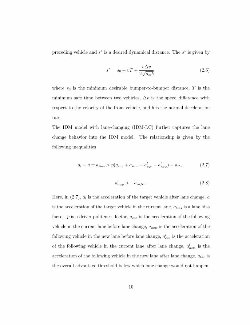
preceding vehicle and s∗ is a desired dynamical distance. The s∗ is given by
s∗ = s0 + vT +v∆v
2√amb
(2.6)
where s0 is the minimum desirable bumper-to-bumper distance, T is the
minimum safe time between two vehicles, ∆v is the speed difference with
respect to the velocity of the front vehicle, and b is the normal deceleration
rate.
The IDM model with lane-changing (IDM-LC) further captures the lane
change behavior into the IDM model. The relationship is given by the
following inequalities
al − a± abias > p(acur + anew − alcur − alnew) + athr (2.7)
alnew > −asafe . (2.8)
Here, in (2.7), al is the acceleration of the target vehicle after lane change, a
is the acceleration of the target vehicle in the current lane, abias is a lane bias
factor, p is a driver politeness factor, acur is the acceleration of the following
vehicle in the current lane before lane change, anew is the acceleration of the
following vehicle in the new lane before lane change, alcur is the acceleration
of the following vehicle in the current lane after lane change, alnew is the
acceleration of the following vehicle in the new lane after lane change, athr is
the overall advantage threshold below which lane change would not happen.
10

Thus, (al−a) is the acceleration gain of the target vehicle after lane change,
while the similar expressions (acur − alcur) and (anew − alnew) represent the
loss in acceleration for the following vehicle in the current lane and the new
lane after lane change. Besides, abias encourages lane change to a particular
side. For example, because the right lane is the default lane in Canada,
vehicles usually drive on the right lane except for overtaking other vehicles.
The left part in (2.7) would be (al − a + abias) if the lane change from left
to right is considered; otherwise, the left part would be (al − a − abias).
In addition, p determines the degree that the behavior of drivers influences
the lane change decisions, and a big value of p will decrease the number
of lane changes. Thus, (2.7) means that a lane change will occur if the
advantage of the target vehicle changing lane to a new lane is greater than
the disadvantage of following vehicles in the current lane and the new lane.
In (2.8), asafe is the maximum possible deceleration which is a positive value.
The deceleration of the following vehicle in the new lane should be above
the safe limit value −asafe. Hence, (2.8) specifies that too quick deceleration
which could cause an accident is not allowable due to the consideration of
safety. Only if both inequalities (2.7) and (2.8) are satisfied would the lane
change happen.
The IDM-LC is more realistic compared with the CSM and FTM models.
A vehicle modeled by IDM-LC is able to change acceleration or deceleration
according to the behavior of neighbor vehicles. Moreover, a vehicle can
change lane if it can get more advantage in the new lane. To evaluate the
11

performance of vehicular networks, a proper realistic vehicle traffic model
should be employed.
2.1.2 Protocol Stack of Vehicular Ad-hoc Networks
(VANETs)
Figure 2.2: DSRC channel designations in the U.S. [2].
Dedicated short-range communications (DSRC) standard suite [2] is consid-
ered as one of the most promising Wireless Access in Vehicular Networks
(WAVE) technologies in VANETs. DSRC is “Dedicated” because the U.S.
Federal Communications Commission (FCC) has allocated 75 MHz of li-
censed spectrum in the 5.9 GHz band for DSRC communications, which
is shown in Fig. 2.2. “Short Range” in DSRC means that the coverage of
DSRC is hundreds of meters.
The spectrum allocated by FCC for DSRC operation in the U.S. is divided
into seven 10 MHz channels with 5 MHz guard band at the low end, as
12

illustrated in Fig. 2.2. The FCC has also designated each channel as either
a Service Channel (SCH) or as a Control Channel (CCH). As we can see,
there are 6 SCHs available for infotainment communications in VANETs.
Figure 2.3: Layered architecture for DSRC in the U.S. [2].
The effectiveness of DSRC is highly dependent on the interoperability of
multiple standards. Fig. 2.3 shows the layered architecture of DSRC. As
seen, the protocols used in DSRC include
• IEEE 802.11p [6]: at the bottom of the stack, which defines the phys-
ical and MAC layers to support communications in vehicular environ-
ments.
13

• IEEE 1609.4: as a MAC sublayer extension that provides multi-channel
operation.
• IEEE 1609.3: the WAVE Short Message Protocol (WSMP) provides
non-routed data exchange and supports safety applications in vehicular
networks.
• IEEE 1690.2: which provides security services such as message authen-
tication and encryption.
• SAE J2735: which specifies the format of messages.
• SAE J2945.1: which describes the minimum performance require-
ments.
As the foundation of DSRC, IEEE 802.11p is an amendment of IEEE 802.11
standards and aims to provide wireless communications in vehicular envi-
ronments.
At the physical layer (PHY), the philosophy of IEEE 802.11p design is to
make the minimum necessary changes to the typical IEEE 802.11 physical
layer. IEEE 802.11p utilizes the well-known orthogonal frequency division
multiplexing (OFDM) technique, originally introduced in the IEEE 802.11a
amendment. At the transmitter, spectral mask is defined to limit the out-
of-band energy. At the receiver, channel rejection is used to filter out energy
that is outside the channel.
At the MAC sublayer, like other standards of IEEE 802.11, IEEE 802.11p
also uses carrier sense multiple access/collision avoidance (CSMA/CA) as
14

the basic medium access. A key purpose of the IEEE 802.11p amendment is
to enable efficient channel access in the vehicular environment without more
overhead than that typically needed in the standard IEEE 802.11 MAC.
The IEEE 802.11 standard defines a concept called the Basic Service Set
(BSS). A BSS is a set of stations that share a common channel to exchange
data information. Before a station can transmit, it must hear the BSS
announcement and go through a series of “setup” steps: including joining,
authenticating, and associating. In a highly mobile vehicular environment,
the opportunity to communicate may be fleeting, and thus “lightweight”
rules for medium access are desired. To achieve this objective, OCB (Outside
the context of a BSS) communications are designed. In the traditional IEEE
802.11, stations belonging to the same BSS exchange data frames. However,
in OCB communications, stations that do not belong to a BSS can also
exchange data frames and do not need the MAC sublayer setup. The OCB
capability is preferred for V2V safety exchanges.
2.1.3 Connectivity of VANETs
To model the connectivity in VANETs, there are some existing analytical
models that differ with respect to the assumptions about the road topology,
the traffic density, the vehicle speed, the vehicles distribution and mobility,
the communication type and the transmission range, and the number of
communication hops. The common objective of these analytical models is
to find out how the network and road parameters affect the connectivity
15

behavior in VANETs.
For V2V connectivity, the vehicle density and the radio communication range
are two major factors which should be considered. There is a common as-
sumption that the inter-vehicle distance should follow an exponential dis-
tribution, which has been shown to be in good agreement with real vehicle
traces under uncongested traffic conditions [10]. Assuming that these inter-
vehicle distances are exponentially distributed and that all vehicles travel
in the same direction, we have the probability that two consecutive vehicles
are disconnected, given by
P{X > R} = e−λR (2.9)
where X is the inter-vehicle distance, λ is the parameter for the exponential
distribution of X and R is the radio communication range. It is obvious
that, as the vehicle density or radio communication range increases, the
probability of disconnected vehicles decreases.
For V2I connectivity, there have been some preliminary field-trials to prove
the feasibility of using V2I communications to support Internet-based ap-
plications, e.g., in [11], [4]. Under the budget constraint, it is not feasible to
cover all roads with road-side APs. In fact, with gaps between the coverage
of two adjacent APs, the V2I connectivity is usually fleeting and intermit-
tent. The experimental study in [11] shows that the median of the V2I
connection duration is around 13 seconds, while the mean duration between
connections is around 75 seconds. Because roadside unit (RSU) is a fixed
16

infrastructure AP node, which is not able to change its deployment with
the dynamic vehicle density, the RSUs are usually assumed to be uniformly
deployed along a road. To increase the probability of access to RSUs, multi-
hop communications of VANETs [12] have been proposed so that a vehicle
in the gap between two APs is able to connect with an RSU via one or more
relay vehicles. By using an efficient relay method, most IP-based applica-
tions can be enabled even in a sparse RSU deployment scenario. However,
the number of hops is often limited (usually less than 3) for simplicity. As a
result, when the vehicle density is low, the vehicle in the coverage gap may
not be able to reach an RSU even using the relay of neighbor vehicles.
2.2 Related Works
Although one primary motivation of developing VANETs is to support safety
applications, which are able to prevent accidents, this thesis focuses on the
drive-thru Internet to support traditional IP-based applications. To satisfy
the specific QoS requirements of different applications in a vehicular environ-
ment, there have been some interesting solutions proposed in the literature.
To leverage the mobility of vehicles, a store-carry-and-forward approach was
proposed in [13] for delay-tolerant applications. Messages that are cached in
a carrying vehicle are buffered to be forwarded to the next vehicle. However,
this method is only suitable for the applications that can accept a long delay
and frequent link breaks.
17

In [14], an enhanced navigation system was implemented based on V2X
(including both V2V and V2I) communications. The messages on road con-
ditions are forwarded to vehicles periodically to help drivers circumnavigate
congested roads and avoid traffic roadblocks. This is an efficient way to
improve transport efficiency and the application does not require real-time
but reliable message delivery.
In [15], a dedicated Low Earth Orbit (LEO) / Medium Earth Orbit (MEO)
link is considered to support vehicular safety applications. Messages which
are exchanged through a satellite link can be delivered to the destination
without relying on RSUs or a multi-hop V2V link. Although the QoS re-
quirement can be satisfied, such a solution is too expensive and probably
will be considered in the future.
In [3], the authors leverage the multi-hop V2V link to enable video streaming
in a highway VANET scenario. The proposed relay scheme can extend
the coverage of an RSU and achieve a higher data rate. Also a video rate
adaptation strategy is developed to adapt the video coding rate according to
the current network condition so as to ensure the smooth and high-quality
playback. However, this adaptive video streaming scheme cannot guarantee
satisfactory performance when the vehicle density is low. Meanwhile, this
scheme only considers one target vehicle which is downloading video packets,
while the other vehicles only act as relay nodes.
In [16], the performance of an IEEE 802.11-based V2I uplink is investigated.
It shows that, when the vehicle density increases, the per-vehicle through-
18

put decreases. However, the performance of both the downlink and uplink is
important since bidirectional applications such as VoIP are becoming pop-
ular. It is known that the voice packet delay must be less than a threshold
to achieve an appropriate QoS guarantee. Apparently, this existing scheme
cannot satisfy the QoS requirement of voice services and the performance
would be even worse especially in a low density scenario.
In [17], an opportunistic relay protocol with a distributed feature is proposed.
In this distributed relay protocol, instead of selecting a relay candidate before
transmission, the RSU first broadcasts the data frame, and the vehicles that
successfully receive the frame become the relay candidates. Each candidate
independently determines its contention window according to its expected
throughput to the destination. The priority is given to the candidate that is
closer to the destination. The broadcast data rate is chosen to achieve the
highest throughput according to the analysis in [17]. However, the best data
rate selection scheme is not able to work perfectly due to the contentions
of relay candidates. A large number of relay candidates can cause collisions
especially in a high density scenario.
In [18], a distributed enhancement algorithm (DEA) for adaptive contention
window size is proposed. In order to increase the throughput, the contention
window has to be adaptive to the channel condition to decrease the collisions.
In DEA, each vehicle counts the portion of busy time during the observation
interval. The contention window is increased if the portion of busy time
becomes larger. This algorithm only works when the density of vehicles is
19

dynamic, but not for a stable vehicular network where the density stays the
same.
It can be seen that these existing schemes need to be improved to simultane-
ously satisfy the QoS requirements of multiple services in different scenarios.
20

Chapter 3
Opportunistic Vehicle Relay
with Adaptive Modulation
In this chapter, we present an opportunistic vehicle relay protocol with adap-
tive modulation to address the relay selection problem of drive-thru Internet.
An analytical approach is developed to evaluate the access performance of
the proposed vehicle relay protocol.
3.1 Relay Selection Problem
Drive-thru Internet [4] is a promising technique that exploits inter-connected
RSUs to enable Internet access for vehicular users on the move. Different
from the cellular networks that have ubiquitous coverage, the RSUs usually
only provide intermittent connectivity due to the high costs of deploying and
maintaining a large number of RSUs. In the literature, there have been many
21

studies on engaging vehicle-to-vehicle (V2V) relay to further complement
the limited coverage of roadside RSUs. Relay selection becomes an essential
problem when deploying an access protocol in the drive-thru Internet.
In general, a centralized relay selection solution aims to identify the best re-
lay(s) by exploiting a global view of the network so as to maximize the trans-
mission success probability and minimize the collision probability. However,
because such protocols require additional time to exchange channel state
information, the incurred overhead and delay are often large.
An opportunistic relay protocol with a distributed feature is proposed in [17]
for the drive-thru Internet. In the opportunistic relay protocol, the RSU
first broadcasts the data and all vehicles that successfully receive the data
contend to relay it to the destination. Each relay vehicle sets its contention
window according to its distance to the destination. A priority (smaller
contention window) is given to the vehicle with a higher expected data rate,
i.e., generally closer to the destination. The study in [17] considers the trade-
off between the broadcast data rate and the achievable throughput. A lower
broadcast rate with a large transmission range increases the number of relay
candidates and the chance of having good relays. Nonetheless, the priority
scheme is assumed to work perfectly. Actually, more candidates also lead to
more intense contention in the forwarding. Hence, the analysis in [17] may
not be able to determine the best broadcast rate, especially for a scenario
of a high vehicle density.
In this thesis, we propose a new opportunistic V2V relay protocol. Due to
22

the distributed contention nature, there is a probability that two or more
relays time out within the collision interval. Hence, the proposed relay
protocol needs to properly address the collisions that occur among the relay
vehicles. Moreover, adaptive modulation at the RSU and the relay vehicles
are taken into account to address the trade-off between involving a sufficient
number of relay candidates and mitigating contention among them.
3.2 System Model
In this chapter, we consider the drive-thru Internet access system illustrated
in Fig. 3.1, where vehicular users can access the Internet via the RSUs. In
particular, we focus on one direction of a highway segment and the downlink
communications from the RSU to a tagged vehicle D. According to the real
vehicular traffic trace in [19], the inter-vehicle distance closely follows the
exponential distribution. Hence, we assume that the vehicles are spatially
distributed along the highway segment as a one-dimensional Poisson point
process (PPP) with an intensity function λ (vehicles/m).
To characterize the wireless fading channel in the vehicular environment, we
assume that the data transmission between a transmitter located at x and
a receiver located at y is subject to Rayleigh fading. That is, the signal-to-
noise ratio (SNR) of the received signal can be written as
γxy =Pt
Nt
hxygxy (3.1)
23

D
RSU
R1 R2
Figure 3.1: System model of drive-thru Internet access with V2V relay.
where Pt is the transmit power, Nt is the power of additive white Gaussian
noise (AWGN), and hxy denotes the small-scale channel fading which is
exponentially distributed with unit mean. The path-loss effect is captured
by gxy = ∥x − y∥−α, where ∥x − y∥ is the Euclidean distance, and α is the
path-loss exponent.
Assume that the RSU and vehicles adaptively select their modulation modes
among binary phase-shift keying (BPSK) and square M -ary quadrature am-
plitude modulation (M-QAM). The bit error rates (BER) of BPSK and M-
QAM are, respectively, given by
PBPSK =1
2erfc
(√Eb
N0
)(3.2)
PQAM =4
k
(1− 1√
M
)Q
(√3k
M − 1
Eb
N0
)(3.3)
where M is the constellation size, k = log2 M , and Eb/N0 is the ratio of bit
energy to noise power intensity. Here, Eb/N0 = γxy ·Bw/Rt, where Bw is
the channel bandwidth (Hz) and Rt is the transmission rate (bps) of the
24

corresponding modulation mode. To successfully decode the received signal,
we assume that the BER needs to satisfy a certain requirement. Accordingly,
the received SNR should be no less than a threshold β [20]. Hence, the
probability of correctly decoding a packet is given by
Pxy = Pr[γxy ≥ β
]= exp
(−β
Pt/Nt
∥x− y∥α). (3.4)
We assume that each vehicle knows its own location, which can be obtained
from its GPS receiver. Further, the location of the tagged vehicle D can also
be piggybacked in the transmitted packet. It should be noted that the RSU
is unnecessary to know the locations of the surrounding vehicles, and each
relay vehicle does not have the location information of others either. As
such, each relay vehicle R can estimate its transmission success probability
PRD to the destination D according to its location information and (3.4)
and choose its backoff time as
W = (1− PRD) · F (3.5)
where the transmission time of a packet at the highest modulation rate is
taken to be one time unit and the maximum backoff time is F time units.
It is expected that a good relay vehicle ends up with a short backoff time
while there is a small probability that two or more relays time out within
an indistinguishable interval c when a collision occurs [21].
Let Ms and Mv denote the constellation sizes of the modulations of the
25

source RSU and a relay vehicle, respectively. In the next section, we will
present our analytical approach to determine the modulation modes.
3.3 Analysis of Proposed Scheme
Consider K modulation modes for the RSU and relay vehicles. Let βi denote
the decoding SNR threshold of the modulation mode i, i = 1, . . . , K. Given
that a modulation mode s is adopted by the RSU to broadcast a packet to
the destination vehicle D, the success probability of the direct transmission
is given by
PSD = exp
(−βs
Pt/Nt
Lα
)(3.6)
where Pt/Nt is the transmit SNR at the RSU and L is the distance between
the RSU and D. Similarly, a neighbor vehicle of a distance r to the RSU
can correctly overhear the packet with a probability
PSR(r) = exp
(−βs
Pt/Nt
rα). (3.7)
These vehicles that correctly overhear the packet are referred to as potential
relays. Thus, the spatial distribution of the potential relays can be viewed
as the result of a p(x)-thinning process [22], where the p(x)-thinning is a
generalized operation that defines a retention probability p(x) for each point
of a PPP and yields a thinned point process by deleting the point with a
probability 1 − p(x). According to Prekopa’s Theorem [22], the resulting
26

point process of these potential relays is also a PPP. The intensity measure
is given by
Λ =
∫ L
0
λPSR(r) dr. (3.8)
When α = 2, we obtain the closed-form expression of Λ as
Λ =λ
2
√π
Ks
erf(√
KsL)
(3.9)
where Ks =βs
Pt/Nt. Thus, the probability of having l potential relays is given
by
Pr[Nr = l
]=
Λl
l!e−Λ, l = 0, 1, 2, . . . (3.10)
3.3.1 Statistics of Potential Relay Vehicles
Due to the probabilistic nature of the opportunistic V2V relay protocol, we
first analyze the statistics of the potential relay vehicles in terms of their
channel conditions, including the average received SNR from a potential
relay to the destination D (denoted by γRD) and the corresponding trans-
mission success probability (denoted by PRD).
According to the channel model in (3.1), we can write the cumulative dis-
tribution function (CDF) of γRD as
Fγ(x) = Pr [γRD ≤ x] = Pr
[Pt
Nt
∥R−D∥−α ≤ x
]= Pr
[∥R−D∥α ≥ Pt/Nt
x
]. (3.11)
27

The CDF in (3.11) depends on the spatial distribution of the potential relay
vehicles and it can be further expressed as
Fγ(x) =1
Λ
∫ L
0
λPSR(r) · 1((L− r)α ≥ Pt/Nt
x
)dr (3.12)
where 1(·) is the indicator function, given by
1(y) =
1, if y > 0
0, if y ≤ 0.
The ratio in (3.12) defines the fraction of the potential relays that satisfy
the condition ∥R−D∥α ≥ Pt/Nt
x, for a given average received SNR x. When
α = 2, a closed-form expression is obtained as
Fγ(x) =λ
2Λ
√π
Ks
erf
(L√Ks −
√KsPt/Nt
x
). (3.13)
Let GP (y) denote the CDF of the transmission success probabilities of the
potential relay vehicles to the destination D. According to (3.4), we have
GP (y) = Pr [PRD ≤ y] = Pr
[exp
(−βv
Pt/Nt
∥R−D∥α)
≤ y
](3.14)
where βv is the decoding SNR threshold if the relay vehicle forwards the
overheard packet to D using a modulation mode v. Here, GP (y) in (3.14) is
28

related to Fγ(x) in (3.11) as follows:
GP (y) = Pr
[Pt
Nt
∥R−D∥−α ≤ −βv
ln (y)
]= Pr
[γRD ≤ −βv
ln (y)
]= Fγ
(−βv
ln (y)
). (3.15)
Based on the estimated transmission success probability, each relay vehicle
can determine its backoff time individually according to (3.5). Then, we can
write the CDF of the backoff time of the potential relay vehicles as
HW (t) = Pr[(1− PRD) · F ≤ t
]= Pr
[PRD ≥ 1− t
F
]= 1−GP
(1− t
F
). (3.16)
3.3.2 Packet Delay and Success Probability
Based on the analysis in the statistics of potential relay vehicles, we can
further evaluate the average packet delay, denoted by T , and the overall
transmission success probability with the opportunistic V2V relay protocol,
denoted by Psuc.
Since we use the time of transmitting a packet at the highest modulation
rate as one time unit, the delay of the direct transmission from the RSU to
D is then K/s time units if the RSU adopts a modulation mode s, where
s = 1, . . . , K. Similarly, the transmission time of a relay vehicle to D is K/v
time units if the relay applies a modulation mode v, where v = 1, . . . , K. In
addition, the relay waits for a random backoff time according to its estimated
29

transmission success probability to D. According to (3.16), we obtain the
mean backoff time as
W =
∫ F
0
[1−HW (t)
]dt. (3.17)
The total average packet delay is then
T = PSDK
s+ (1− PSD)
(K
s+W +
K
v
)=
K
s+ (1− PSD)
(W +
K
v
). (3.18)
The overall transmission success probability depends on the direction trans-
mission and the retransmission via the relay vehicles. Particularly, the re-
transmission is subject to both fading errors and collision loss. Hence, we
have
Psuc = PSD + (1− PSD)P̃RDIc (3.19)
where Ic is the probability of no collision among the relay vehicles and P̃RD
is the average transmission success probability of the best relay that wins
the contention.
Supposing that there are l vehicles (l ≥ 1) that correctly overhear a packet
from the RSU to D, we have PRD,(1) < PRD,(2) < . . . < PRD,(l) denote the l
order statistics of the transmission success probabilities of these potential
relays. According to the opportunistic relay protocol, the best relay has the
highest transmission success probability, PRD,(l), and the shortest backoff
30

time. The CDF of PRD,(l) of the best relay among l candidates is given by{Pr[PRD ≤ y]
}l. Hence, we can obtain the CDF of the highest transmission
success probability among a random number of potential relays as
G̃P (y) =∞∑l=1
Λl
l!e−Λ ·
[GP (y)
]l. (3.20)
Thus, the average transmission success probability is given by
P̃RD =
∫ 1
0
[1− G̃P (y)
]dy. (3.21)
Because the priority scheme that determines a random contention window
does not work perfectly, we need to balance the trade-off of engaging more
high-quality relays and mitigating their collisions. Given l potential relays
that correctly overhear the packet, we denote the l order statistics of their
backoff time by W(1) < W(2) < . . . < W(l). In [21], the authors derive the
joint probability density function (PDF) of the minimum and second mini-
mum of l order statistics as well as the probability that the difference of the
minimum and second minimum is greater than a constant. Based on their
conclusion, if the difference of the minimum and second minimum backoff
time is greater than a constant c, the probability of no collision is given by
Ic|l = Pr[W(2) ≥ W(1) + c
](3.22)
= l(l − 1)
∫ F
c
hW (t)[1−HW (t)
]l−2HW (t− c) dt
31

where hW (t) is the PDF corresponding to the CDF in (3.16). Considering a
random number of potential relays, we can obtain the overall probability of
no collision as
Ic =∞∑l=1
Λl
l!e−Λ · Ic|l. (3.23)
Then, (3.21) to (3.23) can be applied to (3.19) to evaluate the overall success
probability.
As seen from the above analysis, the access performance (T and Psuc) de-
pends on the modulation mode of the RSU for the direct transmission and
that of the relay vehicles for retransmission. The performance is also related
to the environment such as the vehicle density. The proposed analysis well
characterizes the impact of various aspects of the drive-thru Internet system
and can be used to appropriately determine the modulation modes.
3.4 Discussion
In the analysis of proposed scheme, the communication type is restricted to
the downlink from the RSU to a tagged vehicle D. Because the RSU and the
vehicle node are treated fairly during the communication, the analysis results
will be the same if we assume that the scenario is the uplink communication
from the vehicle D to the RSU. The proposed scheme applies to both the
downlink and uplink communications.
In the above analysis, the best modulation modes are selected given that
the distance between RSU and the tagged vehicle D is fixed. As the tagged
32
vehicle moves, which means that the distance between the transmitter and
receiver changes dynamically, the best modulation modes need to be selected
adaptively according to our analytical approach.
Although the proposed opportunistic relay scheme can enhance connectivity
by taking advantage of vehicle relay and adaptive modulation, it may not be
sufficient to support multiple services and guarantee their QoS requirements
simultaneously. In the next chapter, another complementary solution will
be presented to focus on the QoS guarantee for multiple services.
33
Chapter 4
Adaptive Collision Avoidance
with Service Differentiation
In this chapter, we focus on the improvement of access performance and the
support of multiple services in the vehicular network. Firstly, we propose a
new algorithm which is able to change MAC layer parameters adaptively to
improve the overall network performance according to the current vehicu-
lar environment. Then, a multi-service differentiation scheme is presented,
which assigns an appropriate priority level for each specific packet and sched-
ules the transmission order of the packets buffered in the RSU.
34

4.1 MAC Layer Enhancement
4.1.1 Adaptive MAC Layer Parameters
In observing the channel activities, the time interval between two successful
transmissions is defined as a V irtual Transmission T ime (VT) [23]. The
VT consists of the idle time, collision time and successful transmission time.
The idle time is the time when no node is transmitting. The collision time
means the duration that more than two stations are transmitting at the
same time. During the successful transmission time, the packet is delivered
to the destination successfully. It is noted that the idle time and collision
time need to be minimized to achieve a high throughput, which also means
that the collisions among the stations should be reduced.
In wireless MAC protocols such as CSMA/CA, a contention window (CW)
based backoff mechanism is often deployed to decrease the collisions that oc-
cur when more than two nodes start to transmit during the collision interval.
At the beginning of the transmission, a node that is ready to transmit will
sense the channel. If the channel is idle during an arbitration inter-frame
space (AIFS), the node will send the frame immediately; otherwise it will
choose a backoff time uniformly within the interval [0, CW − 1], where the
initial CW size equals CWmin + 1. If the subsequent transmission fails, the
interval size will be doubled until the CW size reaches the value of CWmax.
In a general MAC protocol, the parameters such as CWmin and CWmax
are usually fixed. This often leads to undesired access performance in the
35

vehicular environment, where these parameters should be adaptive to the
dynamic environment. For example, if the density of the vehicles is sparse,
the throughput of the drive-through Internet can increase by choosing a
smaller backoff window size. The waiting time (idle time) is thus reduced
and more packets can be sent during the same interval. When the number
of concurrent transmitting vehicles is large, fixed CW parameters can lead
to aggressive transmissions of the vehicles, so that the throughput becomes
low due to the high probability of collision.
A DEA algorithm is proposed in [18] to adjust the contention window size
of each vehicle in order to be adaptive to dynamic changes of the vehicular
environment and achieve a high throughput. In the DEA algorithm, the
proportion of the busy time over a VT is recorded during each observation
interval (OI). Assume that each vehicle generates the packets at a constant
bit rate. The increase of the proportion of the busy time implies that more
vehicles come to contend for transmitting. Hence, each vehicle enlarges its
own contention window to reduce the probability of collision. However, it
is challenging to select the contention window size appropriately. If the
vehicular environment is stable, which means that the density of vehicles
stay similar, the DEA algorithm does not work because the proportion of the
busy time remains at the same level. The OI defined in this algorithm also
takes a large value, which means that this algorithm updates the contention
window infrequently. Therefore, this algorithm is not able to capture the
fast topology changes of the vehicular network.
36

4.1.2 Adaptive Contention Window Algorithm
In our study, instead of observing the ratio of channel busy time, we design
another metric that captures the dynamics of arriving packets, so that each
vehicle enlarges its contention window size when the number of arriving
packets is considered increasing.
The proposed adaptive contention window (ACW) algorithm is based on
the observation that when more packets are arriving into the drive-through
Internet, the CW size needs to increase to reduce the number of collisions.
We define a monitor interval (MI) which is much shorter than an OI defined
in the DEA algorithm, so that our algorithm is able to follow the dynamic
changes of the vehicular topology. At the MI i, the overall ratio of successful
packet transmissions Sip is defined as
Sip =
N iack
N ipkt
(4.1)
where N iack is the number of ACK received by all the vehicles and the RSU
during the duration MI i, N ipkt is the number of packets sent by all the vehi-
cles and the RSU in the MI i. The RSU participates in every transmission
as the transmitter or receiver. At the end of each MI, the RSU is responsi-
ble for collecting the statistics of transmitted packets and ACK. The RSU
compares the current Sip with the average of the overall packet transmission
successful ratio Sp in the previous MIs and computes the difference αi. If the
value of αi is positive, the RSU confirms that the previous CW adjustment
37
action is correct and takes the same action in the current CW adjustment.
On the other hand, if αi is negative, the RSU will take the opposite action
to change the CW size to the reasonable value.
Algorithm 1 shows the details of ACM. Here, among the actions of the CW
adjustment, CAi = 1 means that the CW size will be increased by CW init;
CAi = −1 means that the CW size will be decreased by CW init. In order to
initiate the algorithm in the first MI, we tentatively set CA1 to 1 to increase
the CW size. At the end of each MI, the RSU calculates a new CW value
according to the packet transmission successful ratio and broadcasts the new
CW value in the update beacon packet to the vehicles in the coverage of the
RSU.
4.2 Multi-service Differentiation
4.2.1 Priority Assignment
The Enhanced Distributed Channel Access (EDCA) mechanism proposed
in IEEE 802.11e is designed for contention-based prioritized QoS support.
There are four application categories (ACs) with different priorities: back-
ground traffic (BK), best effort traffic (BE), voice traffic (VO) and video
traffic (VI). Each AC uses different AIFS and CW sizes to contend for
the transmission opportunity. IEEE 802.11p for the vehicular network also
adopts the EDCA mechanism. The detailed parameter settings in IEEE
802.11p are shown in Table 4.1.
38

Algorithm 1: ACW1: CW = CW init, i = 12: while Vn > 0 do //Vn is the number of vehicles associating with RSU3: if end of ith MI then4: Calculate Si
p
5: αi = Sip − Sp //Calculate difference from previous MI
//Determine adjustment action CAi
6: if i == 1 then7: CAi = 18: else9: if αi > 0 then10: CAi = CAi−1
11: else12: CAi = −CAi−1
13: end if14: end if15: CW = CW + CAi · CW init //Update contention window
16: Sp =Sp·(i−1)+Si
p
i//Update packet transmission successful ratio
17: i = i+ 118: else19: Use previous CW20: Update variables21: end if22: end while
39

Table 4.1: Default parameters in IEEE 802.11p.
AC CWmin[AC] CWMAX [AC] AIFSN[AC]BK 15 1023 9BE 7 1023 6VI 3 15 3VO 3 7 2
Table 4.2: Modified parameters for this study.
AC CWmin[AC] CWMAX [AC] AIFSN[AC] PW[AC]DA 15 1023 9 1VI 7 64 6 2VO 3 7 2 3
In this thesis, we also consider EDCA to support three different application
categories: normal data traffic (DA), video traffic (VI) and voice traffic (VO).
To achieve a better QoS performance, we extend the original parameter
settings. The priority weight (PW) is introduced to differentiate the QoS of
the different application traffic. The modified parameter settings are given
in Table 4.2.
In the drive-through Internet, the DA traffic consists of the uplink packets
sent by the vehicles. The users in the vehicles can also have video streaming
traffic in the downlink from the RSU. The VO packets are transmitted in
both directions between the RSU and the vehicles alternatively. If both
the RSU and the vehicles are assigned with the same parameter settings
in Table 4.2, the QoS requirement cannot be guaranteed as in the original
EDCA mechanism. In most situations, the RSU has more packets to send
compared with the vehicle nodes. As a result, the VO packets from the
40

RSU often experience the larger delay because the number of VO packets
from the RSU is almost equal to the total amount of all the VO packets
from the vehicles. The throughput of the VI traffic can be extremely low
when a great number of neighbor vehicles are transmitting the DA traffic.
Hence, the RSU which has more transmitting packets should be assigned
with a higher priority. In our study, we assume that the setting of the RSU
keep the same as shown in Table 4.2 but the initial CW sizes of the vehicles
will change according to the distribution of the current ACs. Certainly, the
modified CW sizes of the vehicles are larger than the original sizes of the
RSU. Therefore, the packets from the RSU will occupy more transmission
opportunities compared with the packets sent by the vehicles.
There are several related factors that need to be considered in the initial CW
size assignment of the vehicles. For the DA traffic with the lowest priority, it
increases the CW size not only to reduce the collisions that happen between
the same traffic packets but also to release transmission opportunities to
other packets which have the higher priority. Hence, the initial CW size of
the DA traffic is determined by the distribution of DA, VI, and VO vehicles.
We observed in our experiments that the CW size of the DA traffic needs
to increase sharply when there is a high vehicle density. This is to ensure
that the high-priority traffic is not blocked, while the low-priority DA traffic
also has a transmission opportunity. We tested different increasing scales
for the CW size of the DA traffic and found that the power law could work
effectively. The power exponent should be selected appropriately so that
41

the DA traffic is not substantially deprived of transmission opportunities
and the overall throughput can be maximized.
As a result, the initial CW size of the DA traffic for the vehicles is given by
CW initmin[DA] =
(CWmin[DA] ·Nda · PW [DA] + CWmin[V I] ·Nvi · PW [V I]
+ CWmin[V O] ·Nvo · PW [V O]
)·((
λc
λmin
)3
+ Cλ
)(4.2)
where Nda is the number of DA vehicles, Nvi is the number of VI vehicles,
Nvo is the number of VO vehicles, λc is the current density of the vehicles,
PW [DA], PW [V I], PW [V O] are the priority weights of DA, VI, VO traffic,
respectively, and CWmin[V I], CWmin[V O] are the contention window size
for video and voice traffic, respectively. Moreover, λmin is the minimum
value of the vehicle density defined in the simulation, and Cλ is a constant
value. The last term in (4.2) captures the increase scale of the contention
window of DA traffic according to a power function of the vehicle density.
Because all the VI packets are transmitted by the RSU, it is not necessary
to assign a new CW size of the VI traffic for the vehicles, but keeps the
same setting as in Table 4.2. For the VO traffic with the highest priority,
the initial CW size needs to keep a small value to win the contention with
other traffics and achieve a low delay. However, the initial CW size of the
VO traffic has to increase to avoid the internal collisions caused by the VO
vehicles. As the high priority traffic, the VO traffic does not need to consider
42

the number of DA and VI vehicles. To guarantee an affordable delay and
throughput for the VO traffic, we assume that the initial CW size of the VO
traffic increases linearly with the number of VO vehicles. As a result, the
initial CW size of the VO vehicles can be expressed as
CW initmin[V O] = CWmin[V O] + Cvo ·Nvo (4.3)
where Cvo is a constant value.
For the ACW algorithm, only the overall transmission successful ratio needs
to be redefined to support multiple services. The average packet size of
each traffic is introduced to indicate the different contributions of different
services for the overall network throughput. The new overall transmission
successful ratio can be expressed as
Sip =
N iack[DA] · Lda +N i
ack[V I] · Lvi +N iack[V O] · Lvo
N ipkt[DA] · Lda +N i
pkt[V I] · Lvi +N ipkt[V O] · Lvo
(4.4)
where Lda is the average packet size of the DA traffic, Lvi is the aver-
age packet size of the VI traffic, and Lvo is the average packet size of the
VO traffic. Besides, N iack[DA], N i
ack[V I], and N iack[V O] are the number of
ACK packets for data, video, and voice, respectively. Similarly, N ipkt[DA],
N ipkt[V I], and N i
pkt[V O] are the number of sent packets for data, video, and
voice, respectively.
43

4.2.2 RSU Internal Buffer Scheduling
There are two types of packets in the buffer of the RSU: the VI packets and
VO packets. The simplest scheduling mechanism is that these packets are
sent in the order of the arriving time. In this manner, the VO packets of
a higher urgency may wait for a quite long time to transmit. The average
delay of the VO packets will be the same as or even longer than that of
the VI packets. In our scheme, the number of the transmitted VI packets,
Nrsu[V I], and the number of the transmitted VO packets, Nrsu[V O], are
controlled by a scheduling algorithm for the next transmission packet, so
that
Nrsu[V I]
Nrsu[V O]=
Nvi·PW [V I]Lvi
Nvo·PW [V O]Lvo
. (4.5)
With the RSU internal buffer scheduling, the packets with a high priority
will not be blocked by the packets with a low priority and have prioritized
transmission opportunities even when they arrive later than the low-priority
packets. At the same time, the packets with a low priority can be sent if
they get the transmission turns or there are no higher priority packets in
the buffer.
4.3 Summary
It is worth noting that the QoS enhancement solution proposed in this
chapter particularly focuses on multi-service support in drive-thru Internet.
First, the ACW algorithm can adjust the CW size adaptively to decrease the
44

collisions due to the inappropriate MAC layer parameters setting. Then, dif-
ferent priority weights are assigned to different services to distinguish their
priorities in QoS assurance. The RSU buffer scheduling further complements
the above components by properly arranging the transmission order of dif-
ferent buffered packets. When all components work together, we expect that
the QoS requirements of multiple services can be satisfied in a more effective
manner.
45

Chapter 5
Simulator Design and
Implementation
In Chapter 3 and Chapter 4, we presented the QoS enhancement solutions
for drive-thru Internet. To evaluate the performance of the proposed solu-
tions, we also designed and implemented a vehicular network simulator. In
this chapter, we describe the simulated scenario, including the road topol-
ogy, the wireless communications technique (IEEE 802.11p), multiple ser-
vices, and different vehicular traffic models. Then we present the overall
simulation framework consisting of several modules and further explain the
implementation of each module to provide a thorough understanding of the
simulator.
46

5.1 Simulation Scenario
In this thesis, we consider a highway scenario shown in Fig. 5.1 as the de-
fault setting. The RSUs are uniformly placed along the road with an equal
space. All RSUs are connected to the Internet backbone via high-speed
wired links and an RSU can directly communicate with vehicles which are
within its coverage. All vehicles are equipped with GPS devices to locate
their positions and DSRC radios to communicate with other vehicles and
RSUs. The channel conditions (fading, error rate, etc.) are also considered.
For example, the bit error rate and transmission rate vary with the channel
fading.
5.1.1 Network Topology
Application Server
RSU RSU
Figure 5.1: Highway VANET topology (adapted from [3]).
47

On the segment of the highway under study, the vehicle traffic is assumed
unidirectional. The inter-arrival time of vehicles follows an exponential dis-
tribution. The vehicle behavior is specified by a trace file that is generated
according to certain traffic model. The trace file of vehicles is produced after
warming-up running for a sufficient period of time.
5.1.2 IEEE 802.11p
Compared with other standards, IEEE 802.11p is more suitable to provide an
efficient communication method in the vehicular environment. FCC has al-
located 75 MHz of licensed spectrum in the 5.9 GHz band for IEEE 802.11p,
and the communication from other busy band (e.g, 2.4 GHz) cannot interfere
the communication of IEEE 802.11p. At the MAC layer, the basic channel
access is based on CSMA/CA. Also, IEEE 802.11p adopts OCB communi-
cations that do not need extra steps before transmission so as to adapt to
the dynamic topology changes of vehicular networks.
5.1.3 Multiple Services
This research assumes that 3 types of different services should be supported
simultaneously, which is a close assumption for the real environment. It is
assumed that the data service is uni-directional for the uplink. The video
service focuses on downlink streaming from an RSU to the specified vehicle.
The voice service combines uplink and downlink communications together.
Each vehicle can be assigned with one service type according to the simula-
48

tion scenario.
5.1.4 Vehicular Traffic Models
Each vehicular traffic model describes some specified features that capture
the essentials of the real traffic behaviors in building the model. Note that
this traffic model is for the vehicles travelling on the specific highway seg-
ment. It is different from the data traffic models for multiple services. As
the simplest traffic model, CSM does not consider surroundings to determine
the behaviors of the vehicles. According to the CSM model, all vehicles de-
termine their speeds randomly and keep the same all the time. In the FTM
model, the speed of the vehicle changes with the dynamics of the average
vehicle density. When the average vehicle density increases, which means
the road becomes more crowded, the speed of the vehicles slows down. Com-
pared with CSM and FTM models, IDM-LC is more realistic. The vehicle
in the IDM-LC changes its speed dynamically according to the behavior
of the front and the back vehicles. Also, a vehicle can change lane if the
acceleration in the new lane is larger.
5.2 Simulator Framework
To examine the effects of different schemes and factors on the achieved
throughput and delay, we build a computer simulation program with MAT-
LAB 7.14.0 (R2012a) [24]. Fig. 5.2 depicts the simulation framework in
49

��� ���� �� � �� �� � �� � �
���� �� � ���� �� �� ����� ��
�� � �� � �
� � ������ �� ��� �� �� � �� � �
�� � �� ��� � ������ �
�� ���� �� ���
���� � �� � ���
���� �� ��� �� ��� ���� �� �
� � ��� ���
Figure 5.2: Simulator framework.
50

detail, including different modules of the simulator and their relationship to
each other.
The simulator contains three major modules, i.e., traffic model simulator,
multi-service simulator and event-driven MAC layer simulator. Due to the
independence of the major modules, additional supplementary modules (sim-
ulation scenario configuration, data processing center) are necessary to con-
nect the major modules together as a complete simulator.
Before we present further details of different modules, We first introduce
the brief operation procedure of the whole simulator for a good understand-
ing of the design of each separate module. At the very beginning, we need
to choose a specific scenario to trigger the operations of the simulation.
All parameters about the scenario can be defined in the module of simula-
tion scenario configuration. Then according to the traffic model specified in
the simulation scenario configuration, the traffic model simulator produces
the trace file, which includes the moving information of the vehicles during
the simulation time. At the same time, the service assignment of the sce-
nario configuration is provided for the multi-service simulator to produce the
packet information (service type, packet size, generating time). When the
configuration information is ready, the data processing center combines the
service and traffic data together to generate the packet arriving events. The
event-driven MAC layer simulator implements the event processing rules ac-
cording to the scheme that is to be tested and defined in the simulation
scenario. The packet arriving events are delivered to the event-driven MAC
51

layer simulation in the order of time. After the processing of the MAC layer
simulator, the results of packet transmission are sent back to the data pro-
cessing center. At last, the delay and throughput results can be plotted in
the figures at the end of the simulation to present the effects of the tested
scheme.
5.3 Traffic Model Simulator
The traffic model simulator is able to create three types of vehicular trace
(CSM, FTM, and IDM). After the traffic module loads the traffic setting
from the simulation scenario configuration file, the simulation of traffic trace
can start. Based on the parameters for road topology and vehicle distribu-
tion, the road topology is created and each vehicle is placed on the road
according to the defined location distribution. Then all vehicles begin to
move following the indicated behavior rules of the chosen traffic model. The
movement information of vehicle is recorded in the trace file after a suffi-
cient period of warm-up running. At last, the trace file including the traffic
records is stored in the data processing center.
5.4 Multi-service Simulator
For the multi-service simulator, it involves three different service models,
which are data service, video service, and voice service. The data service
contains only uplink packets that reside in the buffer of the vehicle. The
52

downlink video packets, which are dispatched from the video server, are
stored in the buffer of an RSU and be ready to be forwarded to the cor-
responding vehicle when the communication link is available. The voice
service includes both the uplink and the downlink packets, which are trans-
mitted alternately according to the feature of voice service. At first, the
multi-service simulator loads the service assignment condition from the sim-
ulation scenario configuration file. Then the packet information (packet size,
generating time, etc.) can be created during the operations of the service
simulation. Finally, all the packet information is sent to the data processing
center.
5.5 Event-driven MAC Layer Simulator
The MAC layer simulator is built according to basic model of the distributed
coordination function (DCF) of IEEE 802.11. Each station needs to contend
to access the channel with its specified priority. The simulator is designed
as event-driven to improve the efficiency of the simulation. Different events
represent different situations in the real transmission. When a new event
occurs, this event is inserted in an event queue and waits to be handled. The
popping events drive the simulation to move further until all these events
are handled or the simulation time is up.
In the MAC-layer simulator, there are six events that represent different
situations. The relationships of these events can be described clearly in
53

� ������� �� � �����������
� ������� ���� ��
� ����������� �� ��� ���
�� ���� �
� ����� ���������� �
� ����� ���� ������ �
� ����� ������������ ����
� ����� ���������� ���
� ����� �������� �� ���
����� ��� ���� ������� �����
�����
��
�!"##$ %�� &" &$ ���� �
�� �� ����'�� ��
�� �� ����'�� � ��
����
��
� �������� �� �������� ��
����
��
��
���
��
� �� � �
����
��
� � � �
� ��� ( � �
) **$ +�� &" &$ ��� �
� �� � ����� ���
� � � ������� ��
�$&+, �� -. $ ��&" &$ ���� �
�� ����� �/�����
�� �� ���� �/�����
"012 **�� &" &$ ��� � �
� � ������ ����� ��� ���3
�� ������ ����� ��4���3
� �� �
Figure 5.3: Event-driven state transition for MAC layer simulator.
54

Fig. 5.3. It shows that the status of the station is divided into five stages:
idle, ready, backing off, transmitting, and timeout count. The six events
drive the status of the station from one state to another. Following the
generation of the subsequent events, the simulation is able to move forward.
1. Station states
• MAC STA IDLE
A station in the idle state, i.e., MAC STA IDLE, has no more packets
to send at this moment. At the start of the simulation, the states
of all stations are initialized to MAC STA IDLE.
• MAC STA READY
A station in the ready state, i.e., MAC STA READY, means that it
is ready to start the transmission. However, before the station is
able to transmit the packets, it needs to wait for an arbitration
inter-frame space (AIFS) period in which the channel status is
idle.
• MAC STA TRANSMISSION
The state of transmitting, i.e., MAC STA TRANSMISSION, is simple.
It indicates that the station is transmitting a packet.
• MAC STA BACKOFF
If the channel is busy when a station in the state MAC STA READY
attempts to transmit a packet, it has to shift into MAC STA BACKOFF
and start the backoff procedure. Meanwhile, if the sender cannot
55

wait for the arriving of the ACK at the end of timeout period
and the retry time does not reach the maximum number, the sta-
tion also transits to the state of MAC STA BACKOFF. The backoff
counter only counts down when the channel is idle; otherwise the
counter is frozen.
• MAC STA TIMEOUT COUNT
The state MAC STA TIMEOUT COUNTmeans that the station is wait-
ing for the ACK packet after transmitting a packet. No matter
in which state the channel is, the timeout counter counts down
unless it is interrupted by the arriving of the ACK packet or the
timeout counter reaches 0.
2. Events
• EVT MAC PKT DOWN
In our simulator, the event EVT MAC PKT DOWN represents that a
packet arrives at the MAC layer from the upper layer, or the
ACK packet is returned due to the receiving a packet from other
stations correctly. When this event happens, the station may act
differently depending on the current station status. If the station
is in the state of MAC STA IDLE, it will transit to the state of
MAC STA READY. Meanwhile, the packet will be stored in the buffer
of the station, and the buffer state will transit from the state of
BUFFER EMPTY to the state of BUFFER AVAILABLE. However, if the
56

packet arrives when the station is in other states, the station will
keep the current state other than store the packet in the buffer
of the station.
• EVT MAC AIFS SENSE
Before a station starts transmitting a new packet, it is required
to wait for an AIFS so that the channel can be considered as
available. During the event EVT MAC AIFS SENSE, if the state of
the channel becomes busy, the station will transit to the state
of MAC STA BACKOFF. Conversely, if the channel is idle during the
event of EVT MAC AIFS SENSE, the state will shift to the state of
MAC STA TRANSMISSION and the packet is transmitted immedi-
ately.
• EVT MAC DATA TRANS END
This event EVT MAC DATA TRANS END is simple and easy to under-
stand. It means that the station just finishes the transmission
of the packet. No matter whether the collision occurs or not,
the station will transit to the state of MAC STA TIMEOUT COUNT to
count down the timeout counter and wait for the packet of ACK.
• EVT MAC ACK ARRIVAL
The event EVT MAC ACK ARRIVAL represents that the ACK has
arrived at the sender. Because the ACK packet involves the ar-
riving time of the service packet, the delay can be calculated at
this moment. After the event EVT MAC ACK ARRIVAL, the station
57

state can change immediately according to the current state of
the buffer in the station. The station will move to the state of
MAC STA IDLE when the buffer is empty. If there are any packets
in the buffer, the station will shift to the state of MAC STA READY.
• EVT MAC ACK TIMEOUT
In the simulation, a collision may happen when more than two
stations are transmitting at the same period so that the packet
cannot arrive at the receiver successfully. Besides, the channel
fading will also lead to the failure of receiving the packet cor-
rectly. In the above two cases, the receiver is not able to generate
the ACK and the sender will not get the ACK during the timeout
period. Then the event EVT MAC ACK TIMEOUT occurs. In this sit-
uation, three different state changes will occur due to the different
situations. If the retry times is less than the maximum limit, the
state will switch to the state of MAC STA BACKOFF and prepare
for the next transmission. The packet will be dropped when the
number of retries reaches the maximum limit. Meanwhile, the
state will shift to the state of MAC STA IDLE when the station has
no packet to transmit. Or, the station is going to send the next
packet in the state of MAC STA READY.
• EVT MAC BACKOFF COUNTDOWN
Each station maintains a backoff counter and a contention win-
dow for the operation of random backoff process, which intends to
58
decrease the collisions. The counter is assigned a random value
within this contention window at the beginning of each back-
off process. Because the backoff counter keeps frozen when the
channel is busy, the event EVT MAC BACKOFF COUNTDOWN only hap-
pens when the channel is idle. At the end of one time slot, if
the channel is idle and the counter is greater than 0, the sta-
tion will decrease the counter by one and still reside in the state
of MAC STA BACKOFF. However, when the channel is idle and the
counter is equal to 0, it means that the backoff process ends and
the station will shift to the state of MAC STA TRANSMISSION to
transmit the packet immediately.
59

Chapter 6
Experiment Results and
Discussions
We proposed the opportunistic relay with adaptive modulation scheme in
Chapter 3 and the adaptive collision avoidance with service differentiation
scheme in Chapter 4. The design and implementation of the vehicular net-
work simulator have been described in Chapter 5. In this chapter, we first
validate the theoretical analysis for the opportunistic relay scheme proposed
in Chapter 3. Then, we evaluate the two schemes proposed in Chapter 3
and Chapter 4 in the specified simulation scenarios. The performance of the
two schemes combined together is also investigated with our simulator.
60

Table 6.1: System parameters.
Definition Symbol Value
Distance between RSU and D L 1000 m
Channel bandwidth Bw 22 MHz
Number of modulation modes K 6
Minimum success probability Psuc 0.8
Collision interval c 0.01 time units
Maximum backoff time F 5 time units
Transmit SNR Pt/Nt 55 dB
Path loss exponent α 2
Vehicle density λ 0.05 ∼ 0.25 vehicles/m
6.1 Validation of Theoretical Analysis
In this section, we verify with simulations the theoretical analytical approach
that we developed in Chapter 3 for the opportunistic relay with adaptive
modulation scheme. The testing system parameters are given in Table 6.1.
6.1.1 Analysis Accuracy
Fig. 6.1 compares the analysis results with the proposed approach to the
simulation results against the vehicle density λ. As seen, the analysis and
simulation results match well for both the packet delay and success proba-
bility. The overall success probability meets the required minimum bound.
However, there is a turning point of the average packet delay when the ve-
hicle density is 0.19. As the vehicle density increases from zero, the delay
61

0.05 0.09 0.13 0.17 0.21 0.250.2
0.3
0.4
0.5
0.6
0.7
0.8
0.9
1
Vehicle density
Ove
rall
succ
ess
prob
abili
ty
0.05 0.09 0.13 0.17 0.21 0.252.5
3
3.5
4
4.5
5
5.5
6
6.5
Ave
rage
pac
ket d
elay
Success prob. − analysisSuccess prob. − simulationDelay − analysisDelay − simulation
Figure 6.1: Analysis and simulation results of overall success probability andaverage packet delay.
decreases because there are more vehicles on the road and the probability
of finding a good relay is higher with more relays. Then the vehicle density
reaches the turning point which has a high density. The collisions among
relays increase significantly and lead to a longer delay.
6.1.2 Effectiveness
Fig. 6.2 demonstrates the variation of the access performance with the mod-
ulation modes of the AP and the relay vehicles. When a minimum trans-
62

12
34
56 1
23
45
6
0
0.2
0.4
0.6
0.8
1
Modulation mode of relayModulation mode of AP
Ove
rall
succ
ess
prob
abili
ty
(a) Overall success probability.
12
34
56 1
23
45
6
3
6
9
12
15
Modulation mode of relayModulation mode of AP
Ave
rage
pac
ket d
elay
(b) Average packet delay.
Figure 6.2: Variation of overall success probability and average packet delaywith modulation modes.
63

0 0.04 0.08 0.12 0.16 0.20.5
0.6
0.7
0.8
0.9
1
Vehicle density
Ove
rall
succ
ess
prob
abili
ty
0 0.04 0.08 0.12 0.16 0.23
4
5
6
7
8
Ave
rage
pac
ket d
elay
Success probabilityDelay
Figure 6.3: Overall success probability and average packet delay with mod-ulations adapted with vehicle density.
64

mission success probability is set, the best modulation modes can be deter-
mined to guarantee the packet delay is minimized. Given a requirement that
Psuc ≥ 0.8, Fig. 6.3 shows the access performance with adaptive modulation
modes selected by our analytical approach. Clearly, the overall success prob-
ability meets the required minimum bound. This is because the modulation
modes can be effectively adapted with our analysis to balance the trade-off
between engaging good relay candidates for a higher data rate and more
intense collisions with more contending relays.
6.2 Simulation Settings
In the remaining of Chapter 6, we evaluate the performance of the proposed
QoS enhancement solutions (including the opportunistic relay scheme and
the adaptive collision scheme) in multi-service settings. The performance of
the proposed solutions is also compared with representative existing solu-
tions. In this section, we provide the general settings for the simulations. At
the beginning of each simulation run, the scenario of the simulation needs
to be specified in the configuration file and deployed into the simulator.
Consider one example scenario where each vehicle on the highway is ran-
domly assigned one type of applications (VO, VI, DA) for the passengers on
the move. The packets are transmitted between the vehicle nodes and the
RSU which is located in the middle of the highway segment. The RSU is
connected through the edge router to the Internet. The detailed simulation
65
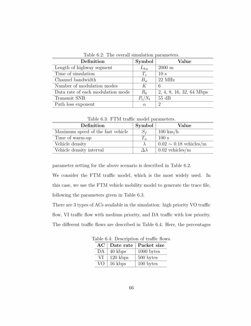
Table 6.2: The overall simulation parameters.
Definition Symbol ValueLength of highway segment Lhw 2000 mTime of simulation Ts 10 sChannel bandwidth Bw 22 MHzNumber of modulation modes K 6Data rate of each modulation mode Rk 2, 4, 8, 16, 32, 64 MbpsTransmit SNR Pt/Nt 55 dBPath loss exponent α 2
Table 6.3: FTM traffic model parameters.
Definition Symbol ValueMaximum speed of the fast vehicle Sf 100 km/hTime of warm-up Tw 100 sVehicle density λ 0.02 ∼ 0.18 vehicles/mVehicle density interval ∆λ 0.02 vehicles/m
parameter setting for the above scenario is described in Table 6.2.
We consider the FTM traffic model, which is the most widely used. In
this case, we use the FTM vehicle mobility model to generate the trace file,
following the parameters given in Table 6.3.
There are 3 types of ACs available in the simulation: high priority VO traffic
flow, VI traffic flow with medium priority, and DA traffic with low priority.
The different traffic flows are described in Table 6.4. Here, the percentages
Table 6.4: Description of traffic flows.
AC Date rate Packet sizeDA 40 kbps 1000 bytesVI 120 kbps 500 bytesVO 16 kbps 100 bytes
66
of DA, VI, and VO application users are 40%, 10%, and 50%, respectively.
The vehicles on the road are assigned with one type application randomly.
This scenario is referred to as the multi-service scenario.
The parameters of the opportunistic relay scheme and the adaptive con-
tention avoidance scheme can be found in the Chapter 4 and Chapter 5,
respectively. The major parameters for the MAC layer setting are chosen
based on the IEEE 802.11p [6].
6.3 Results of Opportunistic Relay with Adap-
tive Modulation
In this section, we firstly evaluate the performance of the opportunistic re-
lay scheme in the uplink scenario. The uplink scenario includes only the
DA traffic users, which is consistent with our analysis for the scheme of
opportunistic relay with adaptive modulation in Chapter 4. Except the dis-
tribution of AC traffic, the parameter settings of the uplink scenario and
multi-service scenario are the same.
For comparison purposes, we consider three different schemes. The Standard
scheme only allows the vehicle to directly communicate with the RSU using
the standard IEEE 802.11p protocol. The Relay scheme enables the vehicle
to access the Internet via both V2I and V2V according to the relay scheme
in [3]. In our proposed ORAM scheme, which is the opportunistic relay with
adaptive modulation, we further introduce adaptive modulation in addition
67

to opportunistic relay.
Fig. 6.4 shows the overall throughput in the vehicular network with the above
three schemes. It can be seen that the throughput of the ORAM is significantly
better than the other schemes. Counter-intuitively, the Standard scheme
even outperforms the Relay scheme. This is because the Relay scheme
simply considers the relay vehicle closest to the RSU as the best relay node,
which cannot select the most appropriate relay vehicle.
It can be seen in Fig. 6.4 that there are two special points when the vehicle
density is in the range of (0.1, 0.12). This observation can be interpreted as
follows. First, when the vehicle density is low, ORAM can choose a low-rate
modulation to engage more relay vehicles such that the overall throughput
is increasing fast with the vehicle density. On the other hand, when the ve-
hicle density continues to increase, the collisions among the vehicles increase
sharply, which drops the throughput. With adaptive modulation, ORAM can
choose a high-rate modulation to reduce the number of potential relay can-
didates and their collisions. Thus, the throughput degrades more slowly.
Because there are a limited number of modulation modes, the transmission
rates of these modulation modes are rather distinct instead of continuous.
At these two special points with a vehicle density in the range of (0.1, 0.12),
ORAM cannot find an appropriate modulation mode in the finite set, which
can satisfy the transmission success probability requirement and maximize
the throughput at the same time. As a result, there is small fluctuation at
these two special points.
68

0.02 0.04 0.06 0.08 0.1 0.12 0.14 0.16 0.180
0.5
1
1.5
2
2.5
3
3.5
4
Density of Vehicles (vehicles/m)
Ove
rall
Thr
ough
put (
Mbp
s)
802.11p;Relay [3]ORAM
Figure 6.4: The overall throughput in the uplink scenario.
69

The average throughput per vehicle and the average delay of the three
schemes are shown in Fig. 6.5 and Fig. 6.6, respectively. As observed,
the performance of the ORAM scheme is much better than that of the other
schemes, although the average delay and throughput become worse as the
vehicle density increases. The results of the uplink scenario shows that the
scheme ORAM is effective in the single DA traffic scenario.
Compared to the uplink scenario, the multi-service scenario is more realistic
but more complex. Fig. 6.7 shows the overall throughput of all the nodes
in the multi-service scenario. It is observed that the ORAM scheme is able
to improve the overall network throughput in the multi-service scenario.
Fig. 6.8 presents the average packet delay in the multi-service scenario. As
seen, the delay of the ORAM scheme is lower than that of the other schemes
only when the vehicle density is sparse. When the vehicle density is low,
the high transmission success probability of the ORAM scheme guarantees a
lower delay. As the vehicle density increases, the more intense contention
also makes the delay larger.
For the performance of the ORAM scheme, the average throughput per vehicle
and the average packet delay of different services are shown in Fig. 6.9
and Fig. 6.10, respectively. In Fig. 6.9, the average throughput per vehicle
satisfies the requirements in Table 6.4 for all services when the vehicle density
is low. As the density becomes high, the average throughput per vehicle
of high priority services (VI, VO) becomes low. In contrast, the average
throughput per vehicle of low priority traffic (DA) stays at a high level even
70

0.02 0.04 0.06 0.08 0.1 0.12 0.14 0.16 0.180
5
10
15
20
25
30
35
40
Density of Vehicles (vehicles/m)
Ave
rage
Thr
ough
put p
er V
ehic
le (
kbps
)
802.11pRelay [3]ORAM
Figure 6.5: The average throughput per vehicle in the uplink scenario.
71

0.02 0.04 0.06 0.08 0.1 0.12 0.14 0.16 0.180
0.1
0.2
0.3
0.4
0.5
0.6
0.7
Density of Vehicles (vehicles/m)
Ave
rage
Del
ay (
sec)
802.11pRelay [3]ORAM
Figure 6.6: The average delay in the uplink scenario.
72

0.02 0.04 0.06 0.08 0.1 0.12 0.14 0.16 0.180
0.5
1
1.5
2
2.5
3
3.5
4
4.5
5
Density of Vehicles (vehicles/m)
Ove
rall
Thr
ough
put (
Mbp
s)
802.11pRelay [3]ORAM
Figure 6.7: The overall throughput in the multi-service scenario.
73

0.02 0.04 0.06 0.08 0.1 0.12 0.14 0.16 0.180
0.5
1
1.5
2
2.5
Density of Vehicles (vehicles/m)
Ave
rage
Del
ay (
sec)
802.11pRelay [3]ORAM
Figure 6.8: The average delay in the multi-service scenario.
74

0.02 0.04 0.06 0.08 0.1 0.12 0.14 0.16 0.180
20
40
60
80
100
120
Density of Vehicles (vehicles/m)
Ave
rage
Thr
ough
put p
er V
ehic
le (
kbps
)
DataVideoVoice
Figure 6.9: The average throughput per vehicle of different services in themulti-service scenario.
75

0.02 0.04 0.06 0.08 0.1 0.12 0.14 0.16 0.180
0.5
1
1.5
2
2.5
3
3.5
4
4.5
Density of Vehicles (vehicles/m)
Ave
rage
Del
ay (
sec)
DataVideoVoice
Figure 6.10: The average delay of different services in the multi-servicescenario.
76

when the vehicle density is high. For the average packet delay of different
services in Fig. 6.10, it can be seen that all services perform well in the
low density situations. When the vehicle density becomes high, the average
delay of the DA service still satisfies the delay requirement but the delay of
other services (VI, VO) is larger than their requirements.
It is worth noting that the QoS of multiple services in the high vehicle
density situations cannot be guaranteed by the ORAM scheme. As the ORAM
scheme achieves a high transmission success probability, the packets can be
delivered to the destination with a larger probability whenever the packets
obtain access to the channel. Because the DA traffic has a packet size larger
than those of the other types of traffic, the transmission of the DA traffic
contributes more to the overall throughput. In the high vehicle density
situations, because the network is congested, the DA traffic of a larger packet
size may occupy the channel for a long duration so that the packets of the
high-priority traffic experience a long waiting time to be transmitted. Till
the end of the simulation, many high-priority packets may be still queued for
transmission, while the DA packets have been delivered to the destination.
6.4 Results of Adaptive Collision Avoidance
with Service Differentiation
In this section, we compare the performance of the proposed adaptive colli-
sion avoidance with service differentiation scheme (ACASD) with that of two
77

other schemes. One is the Standard scheme following IEEE 802.11p. The
other one is the DEA scheme proposed in [18] which monitors the portion of
the busy time and changes the CW size to improve the access performance.
The experiments are conducted in the multi-service scenario. The over-
all throughput and the overall average delay are shown in Fig. 6.11 and
Fig. 6.12, respectively. It is clearly observed that the ACASD scheme per-
forms better than the other two schemes in most situations, although the
average delay is slightly higher in some extremely dense scenarios. This is
reasonable since the size of CW increases with the growth of the vehicle
density and a larger CW size will lead to a longer delay.
To demonstrate the performance of service differentiation with the ACASD
scheme, Fig. 6.13 and Fig. 6.14 show the average throughput per vehicle and
the average delay of different services, respectively. The results demonstrate
that the VO traffic with a high priority achieves a better performance than
the traffic with a low priority. However, the throughput of the VI traffic
drops faster than that of the DA traffic. In this multi-service scenario,
the network is always saturated. The channel resource is scarce and needs
to be reserved for the high priority packets. The VI and VO packets are
all transmitted through the RSU. The VI packets must contend with the
VO packets in the internal of the RSU before accessing the channel. The
opportunity of accessing the channel must be reserved for the VO traffic
which has a highest priority. Thus, the chances for the VI traffic to access
the channel become less.
78

0.02 0.04 0.06 0.08 0.1 0.12 0.14 0.16 0.18
0.4
0.5
0.6
0.7
0.8
0.9
1
1.1
Densities of Vehicles (vehicles/m)
Ove
rall
Thr
ough
put (
Mbp
s)
802.11pDEA [17]ACASD
Figure 6.11: The overall throughput in the multi-service scenario.
79

0.02 0.04 0.06 0.08 0.1 0.12 0.14 0.16 0.180
0.2
0.4
0.6
0.8
1
1.2
1.4
1.6
1.8
Densities of Vehicles (vehicles/m)
Ave
rage
Del
ay (
sec)
802.11pDEA [17]ACASD
Figure 6.12: The average delay in the multi-service scenario.
80

Figure 6.13: The average throughput per vehicle of different services in themulti-service scenario.
81

0.02 0.04 0.06 0.08 0.1 0.12 0.14 0.16 0.180
1
2
3
4
5
6
Density of Vehicles (vehicles/m)
Ave
rage
Del
ay (
sec)
DataVideoVoice
Figure 6.14: The average delay of different services in the multi-servicescenario.
82

6.5 Results of Two Combined Schemes
In this section, the performance of combining the ORAM scheme and the
ACASD scheme is investigated in the multi-service scenario. The combined
case which includes both the ORAM scheme and the ACASD scheme is referred
to as CORAC.
Fig. 6.15 and Fig. 6.16 compare the combined scheme CORAC with the two
individual schemes. As seen, both the overall throughput and the overall
delay of the combined scheme outperform the individual scheme alone. The
overall access performance is guaranteed by the CORAC scheme.
To compare the performance of different services, the average through-
put and the average delay of different services are shown in Fig. 6.17 and
Fig. 6.18, respectively. As seen in Fig. 6.18, the delay of the VO traffic is the
lowest among the three different services. Similarly, Fig. 6.17 shows that the
throughput of the VO traffic always keeps at a high level across the entire
vehicle density range. When the vehicle density increases, the throughput of
the DA traffic decreases faster than that of the VI traffic. The delay of the
DA traffic is always higher than that of the VI traffic. In the CORAC scheme,
the traffic of different application operates in the order of the assigned pri-
orities to first guarantee the QoS of the services with higher priorities. The
results demonstrate that the CORAC scheme is effective in the multi-service
scenario and the QoS requirements for different services can be satisfied.
83

0.02 0.04 0.06 0.08 0.1 0.12 0.14 0.16 0.180
1
2
3
4
5
6
7
Density of Vehicles (vehicles/m)
Ove
rall
Thr
ough
put (
Mbp
s)
ORAMACASDCORAC
Figure 6.15: The overall throughput in the multi-service scenario.
84

0.02 0.04 0.06 0.08 0.1 0.12 0.14 0.16 0.180
0.2
0.4
0.6
0.8
1
1.2
1.4
1.6
Density of Vehicles (vehicles/m)
Ave
rage
Del
ay (
sec)
ORAMACASDCORAC
Figure 6.16: The average delay in the multi-service scenario.
85

0.02 0.04 0.06 0.08 0.1 0.12 0.14 0.16 0.180
20
40
60
80
100
120
Density of Vehicles (vehicles/m)
Ave
rage
Thr
ough
put p
er V
ehic
le (
kbps
)
DataVideoVoice
Figure 6.17: The average throughput of different services in the multi-servicescenario.
86

0.02 0.04 0.06 0.08 0.1 0.12 0.14 0.16 0.180
0.5
1
1.5
2
2.5
3
3.5
Density of Vehicles (vehicles/m)
Ave
rage
Del
ay (
sec)
DataVideoVoice
Figure 6.18: The average delay of different services in the multi-servicescenario.
87

Chapter 7
Conclusion and Future Works
7.1 Conclusion
In this thesis, we proposed QoS enhancement solutions to support multiple
services in drive-thru Internet. First, we proposed the opportunistic vehicle
relay with adaptive modulation scheme (ORAM), for which theoretical anal-
ysis was also developed to validate its effectiveness. Furthermore, to avoid
the unnecessary collisions and assign the appropriate priority for multiple
services, we have proposed the adaptive collision avoidance with service dif-
ferentiation scheme (ACASD), which is able to adjust the MAC layer parame-
ters (contention window size) adaptively according to the current vehicular
network environment.
The simulations that evaluated the performance of the proposed QoS en-
hancement schemes were conducted with our vehicular network simulator.
88

This simulator consists of three major modules, viz., the vehicle traffic model
simulator, multi-service simulator and event-driven MAC layer simulator.
We consider the FTM traffic model, which is the most commonly used one,
to generate the trace file. Three types of applications (DA, VI, VO) are de-
ployed in our simulation scenario. The vehicle users can choose the service
type randomly but satisfy fixed percentages for DA, VI, and VO applica-
tions. The contention-based channel access mechanism of IEEE 802.11 MAC
is also implemented in the event-driven MAC layer simulator to simulate the
packet transmission and contention collisions. Different types of packets are
delivered to the destination through direct or relay transmissions over the
simulated MAC layer channel.
We first evaluate the performance of the ORAM scheme in the vehicular net-
work simulator and compare it with some existing schemes. The simulation
results of the uplink scenario show that the access performance of the ORAM
scheme is much better than that of the other reference schemes. However,
in a more realistic and complex multi-service scenario, the QoS of the ORAM
scheme in the high vehicle density situations cannot be guaranteed. The
low priority traffic (DA) even performs better than the high priority traffic
(VI, VO) in the high density situations. This is because the inappropriate
priority assignments for multiple services in the congested network lead to
the undesired results that the low priority packets occupy more transmission
time.
Then, we carried out the simulation of the ACASD scheme in the multi-service
89

scenario. The simulation results demonstrate that multiple services with dif-
ferent priorities are able to perform appropriately according to their priority
levels. However, in the saturated network, the QoS of the low-priority pack-
ets cannot be guaranteed the QoS performance because the packets of the
high priority have more chances to access the channel.
We have also implemented the combined scheme which includes the ORAM
scheme and the ACASD scheme in the simulation of the multi-service scenario.
The simulation results show that QoS of the combined scheme performs
better than that of each individual scheme. The QoS requirements of all
traffic classes can be satisfied except that the traffic of the low priority is
not able to meet the QoS requirement in the extremely high vehicle density
situations.
7.2 Future Works
Our proposed schemes are able to capture the dynamic factors of the ve-
hicular network and adjust the MAC layer parameters to satisfy the QoS
requirements of multiple services. This work can be further extended in the
following aspects.
Our simulator is able to generate the trace files of three traffic models (CSM,
FTM, IDM). We consider only FTM in this thesis as it is widely accepted.
We can also implement the other two traffic models in our simulation sepa-
rately to see the effects of different traffic models on our proposed scheme.
90

We consider only one RSU that is deployed for one road segment in our
study scenario. In the realistic environment, there can be multiple RSUs
deployed along the road. Due to the mobility of the vehicles , a handoff
strategy should also be implemented to deal with the handover from the
current RSU to the next RSU. Particularly, the handoff strategy should
satisfy the stringent QoS requirement of the voice application.
For the ORAM scheme, we only consider 6 modulation modes available for the
RSU and vehicles to select. In some situations, the transmitter may not be
able to choose the most appropriate modulation mode to achieve the best
access performance. The scheme can be improved by increasing the number
of modulation modes.
91

Bibliography
[1] T. Van Woensel and N. Vandaele, “Modeling traffic flows with queue-
ing models: A review,” Asia-Pacific Journal of Operational Research,
vol. 24, no. 04, pp. 435–461, 2007.
[2] J. B. Kenney, “Dedicated short-range communications (DSRC) stan-
dards in the U.S.” Proceedings of the IEEE, vol. 99, no. 7, pp. 1162–
1182, July 2011.
[3] M. Xing and L. Cai, “Adaptive video streaming with inter-vehicle relay
for highway VANET scenario,” in Proceedings of IEEE International
Conference on Communications (ICC), 2012, pp. 5168–5172.
[4] J. Ott and D. Kutscher, “Drive-thru Internet: IEEE 802.11b for ‘auto-
mobile’ users,” in Proceedings of IEEE Conference on Computer Com-
munications (INFOCOM), 2004, pp. 362–373.
[5] W. L. Tan, W. C. Lau, O. Yue, and T. H. Hui, “Analytical models and
performance evaluation of Drive-thru Internet systems,” IEEE Journal
on Selected Areas in Communications, vol. 29, no. 1, pp. 207–222, 2011.
92

[6] “IEEE standard for information technology–Telecommunications and
information exchange between systems–Local and metropolitan area
networks–Specific requirements; Part 11: Wireless LAN medium access
control (MAC) and physical layer (PHY) specifications; Amendment 6:
Wireless access in vehicular environments,” IEEE Std. 802.11p, July
2010.
[7] A. K. Saha and D. B. Johnson, “Modeling mobility for vehicular ad-hoc
networks,” in Proceedings of the 1st ACM International Workshop on
Vehicular Ad Hoc Networks, 2004, pp. 91–92.
[8] J. D. Fricker and R. K. Whitford, Fundamentals of Transportation En-
gineering. Pearson Prentice Hall, 2004.
[9] M. Treiber, A. Hennecke, and D. Helbing, “Congested traffic states in
empirical observations and microscopic simulations,” Physical Review
E, vol. 62, pp. 1805–1824, 2000.
[10] N. Wisitpongphan, F. Bai, P. Mudalige, and O. K. Tonguz, “On the
routing problem in disconnected vehicular ad-hoc networks,” in Pro-
ceedings of IEEE Conference on Computer Communications (INFO-
COM), 2007, pp. 2291–2295.
[11] V. Bychkovsky, B. Hull, A. Miu, H. Balakrishnan, and S. Madden, “A
measurement study of vehicular Internet access using in Situ Wi-Fi
networks,” in Proceedings of the 12th Annual International Conference
on Mobile Computing and Networking, 2006, pp. 50–61.
93

[12] S. C. Ng, W. Zhang, Y. Zhang, Y. Yang, and G. Mao, “Analysis of
access and connectivity probabilities in vehicular relay networks,” IEEE
Journal on Selected Areas in Communications, vol. 29, no. 1, pp. 140–
150, 2011.
[13] L. Pelusi, A. Passarella, and M. Conti, “Opportunistic networking:
Data forwarding in disconnected mobile ad hoc networks,” IEEE Com-
munications Magazine, vol. 44, no. 11, pp. 134–141, 2006.
[14] J. W. Wedel, B. Schunemann, and I. Radusch, “V2X-based traffic con-
gestion recognition and avoidance,” in Proceedings of the 10th Inter-
national Symposium on Pervasive Systems, Algorithms, and Networks
(ISPAN), 2009, pp. 637–641.
[15] A. Vegni, C. Vegni, and T. Little, “Opportunistic vehicular networks
by satellite links for safety applications,” in Proceedings of the Fully
Networked Car Workshop, Geneva International Motor Show, Geneva,
Switzerland, 2010.
[16] Y. Zhuang, J. Pan, V. Viswanathan, and L. Cai, “On the uplink MAC
performance of a Drive-thru Internet,” IEEE Transactions on Vehicular
Technology, vol. 61, no. 4, pp. 1925–1935, 2012.
[17] J. Yoo, B. S. C. Choi, and M. Gerla, “An opportunistic relay protocol
for vehicular road-side access with fading channels,” in Proceedings of
the IEEE International Conference on Network Protocols (ICNP), Oct.
2010, pp. 233–242.
94

[18] Y. Wang, A. Ahmed, B. Krishnamachari, and K. Psounis, “IEEE
802.11p performance evaluation and protocol enhancement,” in Pro-
ceedings of the IEEE International Conference on Vehicular Electronics
and Safety (ICVES), 2008, pp. 317–322.
[19] N. Wisitpongphan, F. Bai, P. Mudalige, and V. Sadekar, “Routing in
sparse vehicular ad hoc wireless networks,” IEEE Journal on Selected
Areas in Communications, vol. 25, no. 8, pp. 1538–1556, Oct. 2007.
[20] C. Zhai, W. Zhang, and G. Mao, “Uncoordinated cooperative communi-
cations with spatially random relays,” IEEE Transactions on Wireless
Commununications, vol. 11, no. 9, pp. 3126–3135, Sep. 2012.
[21] A. Bletsas, A. Khisti, D. P. Reed, and A. Lippman, “A simple coopera-
tive diversity method based on network path selection,” IEEE Journal
on Selected Areas in Communications, vol. 24, no. 3, pp. 659–672, Mar.
2006.
[22] D. Stoyan, W. Kendall, and J. Mecke, Stochastic Geometry and Its
Applications, 2nd ed. John Wiley and Sons, 1996.
[23] F. Cali, M. Conti, and E. Gregori, “Dynamic tuning of the IEEE 802.11
protocol to achieve a theoretical throughput limit,” IEEE/ACM Trans-
actions on Networking, vol. 8, no. 6, pp. 785–799, Dec. 2000.
[24] MathWorks, “MATLAB R2012a,” http://www.mathworks.com, 2012.
95

Vita
Candidate’s full name: Qing ShenPlace & date of birth: Jiangsu, China. June 6, 1987
University attended:January 2013 - August 2014Faculty of Computer ScienceUniversity of New BrunswickFredericton, New Brunswick, Canada
September 2011 - March 2015College of Software EngineeringSoutheast UniversitySuzhou, Jiangsu, China
Bachelor of Communications EngineeringSeptember 2006 - June 2010School of Telecommunications EngineeringXidian UniversityXi’an, Shaanxi, China
Publications:Qing Shen, Wei Song, and Weichang Du, “Quality of service enhancementfor drive-thru Internet,” Poster at the 11th Research Exposition of UNBFaculty of Computer Science, Fredericton, NB, Canada, May 2014.

Wei Song, Qing Shen, and Weichang Du, “Opportunistic vehicle-to-vehiclerelay with adaptive modulation for drive-thru Internet access,” in Proceed-ings of The 10th International Wireless Communications & Mobile Comput-ing Conference (IWCMC’14), Nicosia, Cyprus, August 2014.