quality control manual - brent gedak welding...
TRANSCRIPT
BRENT GEDAK WELDING LTD
____________________________________________________________________________________
Technical Safety Authority of Saskatchewan
October 25, 2016
Controlled. 1
Revision No. 0
Page 1
______________________________________________________________________
QUALITY CONTROL MANUAL
Brent Gedak Welding Ltd
126 Lamoro Street – Shop/Office
Estevan, Saskatchewan, S4A 1C8 Phone: (306) 634-5150 (Business)
(306)634-5148 (Fax)
ALL WORK TO BE PERFORMED AT
SHOP AND FIELD SITES CONTROLLED FROM THIS LOCATION
MANUFACTURE: PRESSURE VESSELS
FITTINGS (A, E, F &H)
BOILER EXTERNAL PIPING
PROCESS PIPING
POWER PIPING
REPAIR/ALTER: PRESSURE VESSELS
POWER BOILERS
BOILER EXTERNAL PIPING
POWER PIPING
PROCESS PIPING
FITTINGS (A, E, F &H)
WELDER TESTING WELDER/ WELDER OPERATOR TESTING
IN ACCORDANCE WITH: ASME SECTION I
ASME SECTION II A-B-C-D
ASME SECTION V
ASME SECTION VIII, DIVISION I
ASME SECTION IX
ASME B31.1
ASME B31.3
CSA B51
SBPV ACT AND REGULATIONS
NBIC

BRENT GEDAK WELDING LTD
____________________________________________________________________________________
Technical Safety Authority of Saskatchewan
October 25, 2016
Controlled. 1
Revision No. 0
Page 2
______________________________________________________________________

BRENT GEDAK WELDING LTD
____________________________________________________________________________________
Technical Safety Authority of Saskatchewan
October 25, 2016
Controlled. 1
Revision No. 0
Page 3
______________________________________________________________________
STATEMENT OF AUTHORITY SECTION 1
1.1 BRENT GEDAK WELDING LTD has, at my instruction, established this Quality Control
Program. The purpose of the program is to establish the organization and systems
which will be employed in order to achieve full compliance with ASME I, II, V,
VIII Division I, IX, B31.1, B31.3, CSA B51, the SBPV Act and Regulations, the NBIC
and any Customer Specifications.
(a) Boiler external piping is constructed in accordance with the latest edition
and addenda of ASME Section I, II, V and IX, CSA B51 and the additional
requirements imposed by the SBPV Act and Regulations and customer
specifications.
(b) Non-boiler external piping is constructed in accordance with the latest
edition and addenda of ASME B31.1 “Power Piping”, B31.3 “Process
Piping”, Section II, V and IX, and any additional requirements imposed by
the SBPV Act and Regulations, and customer specifications.
.
(c) Fabrication of Pressure Vessels & Fittings (A, E, F &H) shall be fabricated in
accordance with ASME Section VIII, Division I, CSA B51 and additional
requirements imposed by the SBPV Act and Regulations, and customer
specifications.
(d) Boiler & Pressure Vessel and Fitting (A, E, F &H) Alteration and Repair will be
done in accordance with the latest edition and addenda of the
applicable NBIC Code, ASME Code, CSA B51, the SBPV Act and
Regulations, customer specifications, and any additional requirements.
(e) Welders/Welding Operator performance qualification tests shall be
conducted in accordance with the SBPV Act and Regulations, and ASME
Section IX.
(f) All code work shall be performed at BRENT GEDAK WELDING LTD, 126
Lamoro Street, Estevan Saskatchewan, S4A 1C8, and/or field sites
controlled from the above location.

BRENT GEDAK WELDING LTD
____________________________________________________________________________________
Technical Safety Authority of Saskatchewan
October 25, 2016
Controlled. 1
Revision No. 0
Page 4
______________________________________________________________________
1.2 The authority for the administration and implementation of the Quality Control
Program is hereby assigned to the Quality Control Manager, who shall have
sufficient and well-defined responsibilities and organizational freedom to initiate,
recommend and implement solutions for any Quality Control problems.
1.3 It is the responsibility of the Quality Control Manager to obtain complete
compliance with the requirements established in this Manual, on each project
within the Quality Control Manager’s area of authority. When major problems or
conflicts of opinion cannot be resolved within the Organization, they shall be
presented to me for final resolution. The resolution of quality control problems will
not compromise the SBPV Act and Regulations, CSA Codes, ASME Codes, or this
Program.
1.4 The Quality Control Program has the full support of Management.
_______________________________ Nov.22/2016
Brent Gedak Date
President

BRENT GEDAK WELDING LTD
____________________________________________________________________________________
Technical Safety Authority of Saskatchewan
October 25, 2016
Controlled. 1
Revision No. 0
Page 5
______________________________________________________________________
ORGANIZATIONAL CHART SECTION 2
NOTE: More than one position may be held by one person.

BRENT GEDAK WELDING LTD
____________________________________________________________________________________
Technical Safety Authority of Saskatchewan
October 25, 2016
Controlled. 1
Revision No. 0
Page 6
______________________________________________________________________
GLOSSARY OF TERMS SECTION 3
ALTERATION: Any change in the item described on the original Manufacturer’s Data
Report which required a change of design calculations or otherwise affects the pressure
containing capability of the boiler or pressure vessel. Nonphysical changes such as an
increase in the maximum allowable working pressure (internal and external) or design
temperature of a boiler or pressure vessel shall be considered an alteration. A reduction,
i.e., minimum temperature, such that additional mechanical tests are required, shall also
be considered an alteration.
ANSI: American National Standards Institute.
ASME: American Society of Mechanical Engineers.
ASME B31.1: Power Piping.
ASME B31.3: Chemical Plant and Petroleum Refinery Piping.
ASME B31.5: Refrigeration Piping.
ASME, SECTION I: Power Boilers
ASME, SECTION II (Parts A, B, C, and D): Material, Welding Consumables, and Properties.
ASME, SECTION IV: Heating Boilers.
ASME, SECTION V: Nondestructive Examination.
ASME, SECTION VIII, DIV. I: Pressure Vessels.
ASME, SECTION IX: Welding and Brazing Qualifications.
CSA, B51: Boiler, Pressure Vessel and Pressure Piping Code.
CSA, B52: Mechanical Refrigeration Code.
CSA: Canadian Standards Association
C.G.S.B.: Canadian General Standards Board.
BRENT GEDAK WELDING LTD
____________________________________________________________________________________
Technical Safety Authority of Saskatchewan
October 25, 2016
Controlled. 1
Revision No. 0
Page 7
______________________________________________________________________
AUTHORIZED INSPECTOR (AI): A person designated as an Inspector for the purpose of
administering the Saskatchewan Boiler and Pressure Vessel Act and Regulations.
CLIENT’S INSPECTOR: Designated by the Client, this inspector may verify that all required
examinations, testing and inspection of piping systems have been completed to the
extent necessary to ensure that they conform to all applicable Codes, Regulations, and
Client requirements.
JURISDICTIONAL AUTHORITY: A person designated as an Inspector for the purpose of
administering the Technical Safety Authority of Saskatchewan (TSASK) Act and
Regulations.
MAINTENANCE: Any work other than new construction; such as repairs & alterations where
maintenance is being performed all work shall be in accordance with this manual.
NBIC: National Board Inspection Code and reference standard NB-23 used for repairs of
ASME code section boilers, vessels, parts, fittings, etc.
NONCONFORMANCE: Any condition that renders an item unacceptable, or
indeterminate, for use in accordance with the Code, the Client’s specifications, or the
design specifications. Examples of nonconformance include physical defects, test
failures, incorrect or inadequate documentation, material identification/deviations from
prescribed processing, inspection, or test procedures. Nonconformances also include
deviations from this Quality Control Manual.
WELDER PERFORMANCE QUALIFICATIONS: The demonstration of a welder or welding
operator’s skill and ability to produce welds in accordance with the WPS.
P AND ID (Abbreviation): Process and Instrumentation Drawing.
PRESSURE EQUIPMENT INSPECTOR: A person who conducts code inspections on behalf of
an insurer or owner in connection with a quality management system and holds a valid
licence certified by TSASK.
PROCEDURE QUALIFICATION RECORD (PQR): The document that records the test results
which establish the properties of the weldment.
REGISTERED DESIGN: Any drawings, specifications, and information which have been
reviewed and registered by the Technical Safety Authority of Saskatchewan.
REPAIR: Any work necessary to restore a boiler or pressure vessel to a safe and satisfactory
operating condition, provided there is no deviation from the original design.

BRENT GEDAK WELDING LTD
____________________________________________________________________________________
Technical Safety Authority of Saskatchewan
October 25, 2016
Controlled. 1
Revision No. 0
Page 8
______________________________________________________________________
QUALITY CONTROL MANAGER (QCM): The designee that manages and controls the
Quality Management System program and assures compliance with Code and
Jurisdictional requirements. The QCM has the authority and organizational freedom to
identify quality control problems and to initiate, recommend and provide solutions to
those problems. The QCM shall have direct access to the highest level of management at
which decisions are made and provide specific functions as detailed in this Quality
Management System Manual. The QCM shall verify the correction of nonconforming work
and shall control further processing, delivery or application of nonconforming work until a
disposition has been obtained. The QCM shall be the liaison with the Jurisdictional
Authority.
QUALITY CONTROL REPRESENTATIVE: The designee of Quality Control Manager. The
designee can function in any role the Quality Control Manager deems acceptable. The
designee is responsible to the Quality Control Manager for all assigned duties within the
scope of the Manual.
TECHNICAL SAFETY AUTHORITY OF SASKATCHEWAN ACT:
The TSASK Act is the legislation that introduced TSASK as an Authority (or Delegated
Administrative Organization) for enforcing the Saskatchewan Provincial Act and
Regulations correctly titled “The Boiler and Pressure Vessel Act, 1999” and “The Boiler and
Pressure Vessel Regulations”. These Act and regulations may be referred to as SBPVAR –
Saskatchewan Boiler and Pressure Vessel Act and Regulations.
UNCONTROLLED MANUAL: A Quality Control Manual issued upon request and current at
the time of issuance, but which is not maintained by subsequent revisions or updating.
WELDING PROCEDURE SPECIFICATIONS (WPS): The document which describes in detail all
of the variables which are essential, supplementary essential, and nonessential to the
welding processes employed by the ASME Code, Section IX.
WELDING EXAMINER: Qualified personnel designated by the individual who has signed
the Statement of Authority in this Quality Control Manual to perform the duties as defined
in this Quality Control Manual. The Welding Examiner reports directly to the Quality
Control Manager. The Welding Examiner must hold a Welding Examiner Certificate of
Competency issued pursuant to the Technical Safety Authority of Saskatchewan Act and
Regulations.

BRENT GEDAK WELDING LTD
____________________________________________________________________________________
Technical Safety Authority of Saskatchewan
October 25, 2016
Controlled. 1
Revision No. 0
Page 9
______________________________________________________________________
MANUAL CONTROL SECTION 4
4.1 The Quality Control Manager will issue controlled copies of the Manual in
accordance with the list of Manual Holders as stated in Exhibit A. Each Manual will
bear the same control number on its title page as shown on the List.
4.2 An internal audit shall be conducted at the 18 month interval over the 3 year
certification which consists with the reviewing the manual and quality system
coincident with the issue of any Code edition or addenda, standards, and revising
the manual and or system as necessary to incorporate any required changes and
implementing any changes within 6 months of the issue date of the new edition or
addenda. The intent is to fully audit the Quality System one time during the 3 year
certification period. When revisions are required, they are presented to the
Authorized Inspector for his acceptance, and then distributed to Manual Holders.
4.3 Any revision made to this Quality Control Manual will be BOLDED and UNDERLINED
to Identify the change. Revisions made to all controlled copies on next submission
of the manual, the bolded text will be removed and only new changes will be
bolded text.
4.4 Revisions will be approved by the Quality Control Manager and submitted to the
Authorized Inspector for his review and acceptance prior to issue. The revision
acceptance will be signed off on the Table of Contents page, which will also
reflect the revision number and revised date.
4.5 Revised sections of the Manual are then issued by the Quality Control Manager to
Manual Holders on the list, together with a revised Table of Contents page showing
the latest Revision Number and Date of each section of the Manual, and the
dated signatures of the Quality Control Manager and the Authorized Inspector.
4.6 Revised exhibits pages are issued individually with a revised “Sample Forms” page.
4.7 A current copy of the Quality Control Manual is available for use by the Authorized
Inspector and the Authorized Inspectors Supervisor at the shop and at field sites.
4.8 The Quality Control Manager is responsible for maintaining the contact between
the Company and the Authorized Inspection Agency.
4.9 Uncontrolled manuals may be issued to outside organizations for information only,
and shall not be used within BRENT GEDAK WELDING LTD “Uncontrolled Copy”
shall be prominently indicated on the front page of these manuals.
BRENT GEDAK WELDING LTD
____________________________________________________________________________________
Technical Safety Authority of Saskatchewan
October 25, 2016
Controlled. 1
Revision No. 0
Page 10
______________________________________________________________________
BRENT GEDAK WELDING LTD
____________________________________________________________________________________
Technical Safety Authority of Saskatchewan
October 25, 2016
Controlled. 1
Revision No. 0
Page 11
______________________________________________________________________
PREJOB REVIEW SECTION 5
5.1 If any of the required quality control functions are to be performed by the
Owner/Subcontractor, then the Quality Control Manager must make the
Owner/Subcontractor aware that, under the SBPV Act and Regulations, any
Owner/Subcontractor who assumes responsibility for any Quality Control functions
such as material receiving, inspection, material traceability, welding, welder
supervision, performing pressure tests or preparing quality control records must
have their own Authorized Quality Control Program. If the Owner/Subcontractor
does not have an Authorized Quality Control Program for performing these
functions, then the Owner/Subcontractor cannot perform them.
5.2 Prior to the commencement of any work performed by BRENT GEDAK WELDING
LTD and at field sites controlled from the above location to the discretion of the
Quality Control Manager a meeting shall be conducted with the Client to establish
responsibilities for:
a. the supplying of engineering
b. job access – safety – work facilities
c. responsibility for supplying materials
d. responsibility for NDE and testing
e. procedures for alteration/repair documentation
f. communication and contract personnel
g. client requirements for inspection and documentation
h. on-site nonconformities
i. the establishment of any third party involvement
j. for any non-pressure requirements
k. time tables
l. operations and construction cooperation
m. transportation and shipping
n. insurance requirements
o. damage resulting from: any Contractor personnel or Client’s
personnel
p. the loss of material due to theft
q. lay down and storage facilities
r. on-site equipment availability, and
s. the Client’s engineering standards
t. calculations
u. systems for registration
v. notification to Authorized Jurisdiction
The Contract Review (Exhibit V) shall be completed, signed and dated by the Quality
Control Manager and the Owner’s Representative prior to the start of the project if owner
does not supply scope of work documentation.

BRENT GEDAK WELDING LTD
____________________________________________________________________________________
Technical Safety Authority of Saskatchewan
October 25, 2016
Controlled. 1
Revision No. 0
Page 12
______________________________________________________________________
DESIGN & SPECIFICATION CONTROL SECTION 6
6.1 This section outlines the system for the review, approval, distribution and retrieval of
all design drawings and specifications, including: specifications, P and ID’s,
mechanical flow sheets, line equipment lists, material lists, spool sheets and,
isometrics. The Owner is responsible for preparation and approval of all design
specifications, drawings and calculations and for submitting the design to the
Jurisdictional Authortiy for registration when applicable.
The Quality Control Manager will issue the latest revised drawings and documents
and recall and destroy all superseded documents, one copy of each superseded
drawing or document marked “VOID” shall be kept for reference by the Quality
Control Manager in the job file.
6.2 If the drawing and calculations are completed by the Owner/subcontractor, no
work shall commence until design registration is complete or prior approval has
been received in writing from the Owner allowing the start of the job.
In the event any pressure piping fabrication is to be initiated prior to design
registration, the Owner/Subcontractor shall have the design package submitted to
the Jurisdictional Authority in advance of the construction process. This will include
the drawings and calculations. The Authorized Inspector shall have been notified
for permission to begin construction prior to registration. The design cannot be
commissioned into operating service until design registration is completed and any
deficiencies identified through the registration process shall be corrected to the
satisfaction of the Authorized Inspector. The Owner shall agree to all these
conditions in writing.
All pressure piping fabricated requires the completion of the Pressure Piping
Construction Data Report and the Completion of Construction Report signed off
and forwarded in the job file.
6.3 The Quality Control Manager is responsible for the review and control of all design
documents. His duties include:
(a) To review design specifications and drawings to ensure these contain sufficient
information to construct pressure vessels, fittings, and piping system in
accordance with Code requirements; and to contact the owner if additional
information is needed. Details normally required on drawings/design
specifications include:
(1) Material description including; material specification, grade,
dimensions, schedule, type and rating.
BRENT GEDAK WELDING LTD
____________________________________________________________________________________
Technical Safety Authority of Saskatchewan
October 25, 2016
Controlled. 1
Revision No. 0
Page 13
______________________________________________________________________
(2) Design pressure and temperature of system.
(3) Nondestructive examination and extent (ie. random, 100%)
(4) Test pressure and medium.
(5) Heat treatment temperature and holding time if applicable.
(6) Construction details, supports etc.
(7) Welding procedure information (W.P.S. numbers/electrode
classification)
(8) Applicable Code of Construction
(9) Approval of construction by a sign off from the Quality Control
Manager.
(10) Additional requirements.
(b) To obtain written approval from the Owner prior to making any proposed
changes.
(c) Spool Drawings
Review and approve any spool drawings prepared by BRENT GEDAK
WELDING LTD from Owner’s design specifications and drawings.
(d) Job File
To initiate a Job File and ensure that all design specifications, Owner’s
material lists, P.O.’s etc. are kept in this file, each identified with the job
name.
(e) Drawing and Specification Distribution
- To maintain a drawing index (Exhibit R) indicating the drawing title,
number and revision, copies issued and the name of the person to whom
they were issued.
- To issue approved drawings, specifications, welding procedures, P.O.’s
material lists and applicable quality control forms to each Quality
Control Representative.
- To recall and destroy all superceded documents. Alternatively, these
may be marked “Void” and kept in Job File.
(f) As Built Drawings
To obtain the owner’s approval of any revisions and submit the final “as
built” drawing to the owner along with all pertinent records.

BRENT GEDAK WELDING LTD
____________________________________________________________________________________
Technical Safety Authority of Saskatchewan
October 25, 2016
Controlled. 1
Revision No. 0
Page 14
______________________________________________________________________
6.4 Handling of Drawings and Specifications at Site
The Quality Control Manager shall:
(a) Maintain the Job File at site containing as built drawings and documents,
issue drawings and specifications to site personnel, collect and mark
“VOID” or destroy all superceded documents.
(b) Forward a copy the Job File to the Owner when the job is completed.
6.5 The Quality Control Manager will complete the Statutory Declaration (Exhibit M) for
all items that qualify as pressure fittings (A, E, F &H), and submit this document in
duplicate along with a Design Registration Application (Exhibit Q), drawings,
calculations and specifications to the TSASK or applicable jurisdiction. Before the
manufacture of pressure fittings for installation in other jurisdictions, the applicable
jurisdiction should be contacted to determine requirements for design and
construction.
6.6 For any pressure piping that meets or exceeds .5m or 17 cubic feet in volume
registration of the design shall be required for submission to the Jurisdiction.
Two copies of the applicable drawings/ prints and the General Engineering
Requirements for Design & Construction of Pressure Piping Systems shall be
forwarded for review and acceptance prior to construction.

BRENT GEDAK WELDING LTD
____________________________________________________________________________________
Technical Safety Authority of Saskatchewan
October 25, 2016
Controlled. 1
Revision No. 0
Page 15
______________________________________________________________________
MATERIAL CONTROL SECTION 7
PROCUREMENT
7.1 Material required for fabrication will be purchased and supplied by BRENT GEDAK
WELDING LTD or Owner supplied.
(a) Purchased Material
All materials required shall be listed on a Material Requisition/Receiving
Report Form (Exhibit N), showing a complete description with job name,
material specification, grade of material, as per design drawings and/or
Owners specifications.
After this has been checked and approved by the Quality Control
Manager by signing and dating, it will be issued to the Purchasing
Department.
The Purchasing Manager shall order all materials on a Purchase Order after
it has been approved by the Quality Control Manager. The Purchase
Order shall contain all information detailed on the Material Requisition
Form, and shall include a request for Mill Test Reports and supplementary
requirements and shipping instructions. This material order must conform to
the specifications of ASME, Section II Code. All Mill Test Reports and
Purchase Orders will be maintained in the Job File and will be made
available to the Client’s Inspector and the Authorized Inspector.
Material released for fabrication will conform to the exact specifications
shown on the shop drawings and will be checked and verified by signature
of the Quality Control Manager. Any nonconforming material will be
handled in accordance with Section 12, “Correction of
Nonconformances”.
(b) Client-supplied Material
It is the responsibility of the Quality Control Manager, or his designate, to
ensure that materials are received in accordance with the Client’s
specifications and are identified with material specifications in
accordance with the Client’s Material List/Purchase Order. A Material
Requisition/Receiving Report Form (Exhibit N) will be issued, showing
customer supplied material.

BRENT GEDAK WELDING LTD
____________________________________________________________________________________
Technical Safety Authority of Saskatchewan
October 25, 2016
Controlled. 1
Revision No. 0
Page 16
______________________________________________________________________
BRENT GEDAK WELDING LTD will receive all materials that the client has
selected to ship. Materials will be listed in a filing system by job name,
with full description and specifications, including MTR’s, grade and type of
material.
Material released for fabrication will conform to the exact specifications
shown on the shop drawings and will be checked and verified by signature
of the Quality Control Manager. Any nonconforming material will be
handled in accordance with Section 12, “Correction of
Nonconformances”.
Material left over from a job will either by returned to the vender/ owner or
kept as stock for future code fabricating usage. The material will be
traceable to the MTR by the original job name applied as per Section 7.2 of
the manual.
IDENTIFICATION AND TRACEABILITY
7.2 The identification of each item, component, or part is the responsibility of the
Quality Control Manager or his designee who shall, upon receipt of material,
check them against the received MTR and the Purchase Orders and clearly
identify them by marking the items with the job name with a paint stick. Materials
shall be checked for compliance including O.D., thickness, material specifications,
chemical composition, gross defects, etc.
The Quality Control Representative will verify that the material test reports (MTRS)
include physical tests and chemical analysis and conform to ASME Code Section II
requirements, same edition and addenda as indicated on the construction
drawing. If the MTRS conform to ASME Code Section II, the Quality Control
Representative will initial the MTRS. The Material Requisition/Receiving Report will
then be completed with the applicable information (Exhibit N).
The withdrawal of materials from stock will require checking by the Quality Control
Manager prior to fabrication or installation.
For small multiple parts or fittings, bulk storage identification may be used by
applying markings to a container with a quantity, heat number and job name.
This would be adequate to prove the materials have been accepted for
fabrication and segregated for a particular job.
BRENT GEDAK WELDING LTD
____________________________________________________________________________________
Technical Safety Authority of Saskatchewan
October 25, 2016
Controlled. 1
Revision No. 0
Page 17
______________________________________________________________________
At the start of a job, the Quality Control Manager will determine whether color
coding of piping or job name application to the required materials will be
adequate or suitable for material traceability.
The Quality Control Representative will if applicable, color code acceptable pipe
material in accordance with the Material Identification Color Coding (Exhibit H),
by painting a stripe, the full length of the pipe. Color coding ensures that
traceability to each material specification is maintained. Heat numbers will be
marked with a paint stick on all cut lengths. Shop-fabricated piping shall be
identified with a spool number. The color code shall be available for verification
by the Authorized Inspector and the Client’s Inspector.
If the Client color code is used, then the Client’s color code schedule shall be
available at the shop/field.
For fittings, the original manufacturer’s stamping will be used to maintain
traceability to the specifications.
NONCONFORMING ITEMS/MATERIAL
7.3 Should it be necessary to substitute material outside the acceptable guidelines of
the NBIC for the repair or alteration of a registered design of a pressure vessel or
fitting, the proper substitutions must be approved in writing by the Owner’s
Representative, the Quality Control Manager and accepted Authorized
Inspector. In such instance, revised documents will be prepared and issued in
accordance with Section 6. When acceptable to the AI, minor changes may be
indicated on the existing drawing with the approval signature of the Designer and
the Quality Control Manager. Material Substitution Report (Exhibit U) shall be
completed and forwarded for acceptance prior to the repair/ alteration change
being performed.
Any material/item that does not meet above requirements shall be considered
a nonconformity and shall be processed in accordance with Section 12 of this
Manual. A copy of the nonconformance shall be kept in the job file for the
Authorized Inspectors review and signature if required.

BRENT GEDAK WELDING LTD
____________________________________________________________________________________
Technical Safety Authority of Saskatchewan
October 25, 2016
Controlled. 1
Revision No. 0
Page 18
______________________________________________________________________
EXAMINATION AND INSPECTION PROGRAM SECTION 8
8.1 The Quality Control Manager shall ensure the Client’s Inspector and the Authorized
Inspector will be informed reasonably in advance of the commencement of
construction, and kept informed of progress throughout construction.
The Quality Control Manager shall ensure an inspection form is applicable to the
examination and test points of the work being performed (Exhibit I, J or Exhibit K).
The Quality Control Manager shall be responsible for ensuring all inspections are
performed. The inspection form is to be presented to the Authorized Inspector
and/or Owner for the designation of hold points.
8.2 It is the responsibility of the Quality Control Manager to ensure that fabrication
does not proceed without confirmation that the required inspections have been
performed on all material or parts prior to their release for construction.
8.3 The Quality Control Manager shall ensure material traceability, welding
specifications, procedure qualification records, joint preparation, fit-up,
dimensions, alignment, welds, etc are addressed for all code job packages. These
functions are detailed in Section 10, “Welding Control”.
8.4 In-process inspections are performed on Boilers & Pressure Vessels at the inspection
points required. These inspections are dated and signed by the Quality Control
Manager or his designate. The completion of required examinations,
inspections, and tests, as well as the documentation for ensuring traceability of
radiographs and other nondestructive examinations reports to individual
weldments, shall be by means of the Boiler and Pressure Vessel Traveler Form
(Exhibit I) or marked-up drawings.
8.5 In-process Repair/ Alteration inspections are performed on boilers & pressure
vessels at the inspection points required. These inspections are dated and signed
by the Quality Control Manager/Representative. The completion of required
examinations, inspections, and tests, as well as the documentation for ensuring
traceability of radiographs and other nondestructive examinations reports to
individual weldments, shall be by means of the Boiler and Pressure Vessel Repair/
Alteration Traveler Form (Exhibit K) or marked-up drawings.
8.6 The Quality Control Manager shall notify the Authorized Inspector and the Owner’s
Inspector (if applicable) of any upcoming hold points sufficiently in advance in
order to allow for adequate scheduling of time to take place for the required
inspections.

BRENT GEDAK WELDING LTD
____________________________________________________________________________________
Technical Safety Authority of Saskatchewan
October 25, 2016
Controlled. 1
Revision No. 0
Page 19
______________________________________________________________________
All completed pressure piping systems shall be examined by the Quality Control
Representative for specifications, and code requirements. Examples of items to be
examined are given in the Pressure Piping Compliance Plan (ITP) (Exhibit J) and the
Pressure Piping Examination Guide (Exhibit W).
8.7 All pressure tests, hydrostatic tests, pneumatic tests, service tests, and sensitive leak
tests shall be completed in accordance with design specifications and applicable
Code requirements. All pneumatic tests to be completed for code purposes shall
be subject to approval by the Authorized Inspector prior to testing.
The Quality Control Manager shall prepare the Manufacturer’s Data Report and
verify that the nameplate stamping information is complete and correct in the
Sample Nameplate (Exhibit P {a}) format. After the pressure test has been
accepted, the QCM will certify the Manufacturer’s Data Report by signing and
dating, and then present it to the Authorized Inspector for signoff and
acceptance. For any pressure piping, the Pressure Piping Data Report and
Completion of Construction Report for Piping (Exhibit B) shall be signed and dated
by the QCM and presented for signoff and acceptance to the Authorized
Inspector and/or Owner’s Inspector when applicable.
The Quality Control Manager will distribute the Manufacturer’s Data Report with
any required Partial Data Reports attached to;
a) the Authorized Inspector,
b) the customer,
c) the job file, and
d) the jurisdiction where the vessel will be located.
8.8 The Job/ documentation file shall be reviewed for completion by the Quality
Control Manager and submitted to the Client. The package shall include all the
required records and any applicable signoffs of acceptance by the Client’s
Inspector and/or the Saskatchewan Boiler and Pressure Vessel Safety Authorized
Inspector
8.9 Category “A”, “E”, “F” and “H” pressure fittings will be manufactured in
accordance with this written quality system with the following modifications and
exceptions:
Inspection by the Authorized Inspector is not mandatory for the
manufacture of pressure fittings. All inspections performed by the

BRENT GEDAK WELDING LTD
____________________________________________________________________________________
Technical Safety Authority of Saskatchewan
October 25, 2016
Controlled. 1
Revision No. 0
Page 20
______________________________________________________________________
Authorized Inspector as described in this manual or by Code, shall be
performed by the Quality Control Manager except as follows:
In instances where a Category “H” Fitting Containing Lethal
Substances is to be manufactured, fabrication inspection by the
Authorized Inspector is required by CSA B51. The required
fabrication inspection shall be conducted in accordance with the
new pressure vessel criteria contained in this section of the manual.
The Travel Sheet (Exhibit I) used for construction of new pressure
vessels shall be used for each fitting or concurrent batch of fittings
and shall be signed and dated by the Quality Control Manager, as
each function is completed for each fitting or batch of fittings.
The Quality Control Manager shall verify the hydrostatic test
pressure to the approved drawing and witness the hydrostatic test.
Each Category “A” or “E” pressure fitting (and category “H” fittings that are not
miniature pressure vessels) will as a minimum, be identified in accordance with
specifications MSS SP-25, and where possible the full identification as shown in the
example below will be stamped on the fitting:
BRENT GEDAK WELDING LTD
CRN S/N
MAWP PSI AT DEG. F
MDMT DEG. F AT PSI
YEAR BUILT
BRENT GEDAK WELDING LTD
____________________________________________________________________________________
Technical Safety Authority of Saskatchewan
October 25, 2016
Controlled. 1
Revision No. 0
Page 21
______________________________________________________________________
REPAIRS AND ALTERATIONS SECTION 9
NOTE: All procedures of this manual are to be followed except as indicated in this section,
and will also be in accordance with NB-23 of the NBIC for repairs and alterations.
9.1 The Quality Control Manager shall ensure that no repair or alteration shall be
made to any pressure retaining component of a boiler, pressure vessel, fitting, fired
heater pressure coil, or piping without the prior notification of the Authorized
Inspector or Owner’s Inspector and that all procedures of this manual will be
followed.
9.2 Subject to the approval of the Authorized Inspector, the Quality Control Manager
shall develop a repair/alteration procedure if the document has not been
provided by the owner or his representative. The Quality Control Manager shall
ensure an inspection form is applicable to the examination and test points of the
work being performed (Exhibit J, or Exhibit K). The Quality Control Manager shall
be responsible for ensuring all inspections are performed. The inspection form is to
be presented to the Authorized Inspector and/or Owner for the designation of
hold points.
9.3 If requested by the Authorized Inspector, the Quality Control Manager shall ensure
all procedures, calculations and drawings (if applicable) are submitted to the
Authorized Inspector prior to start of work on a Repair/Alteration Report (Exhibit D).
9.4 The Quality Control Manager shall ensure that when an alteration to a boiler or
pressure vessel is made such as when the maximum allowable working pressure,
allowable temperature, or the minimum design metal temperature is changed, an
additional name plate shall be affixed adjacent to the original name plate of the
boiler or vessel. This additional name plate shall show the following:
(a) specify if an alteration or re-rate;
(b) name of company responsible for the change;
(c) maximum allowable working pressure and temperature;
(d) minimum design metal temperature (where applicable);
(e) the date of alteration;
(f) CRN.
9.5 Letter sizing on name plates shall be 5/32” (4mm) or as applicable ASME code
dictates, an example of the nameplates is referenced on Exhibit “P (b)”.
BRENT GEDAK WELDING LTD
____________________________________________________________________________________
Technical Safety Authority of Saskatchewan
October 25, 2016
Controlled. 1
Revision No. 0
Page 22
______________________________________________________________________
9.6 Code Inspection Requirements:
When field or on plant-site repairs are performed for an organization with a TSASK
Safety Authorized Quality Management System Inspection Program, the Quality
Control Manager shall establish who will be responsible for the Code inspections
when the contract is initiated.
Owners who have a TSASK Safety Quality Management System Certificate of
Authorization may be authorized to perform the repair Code inspections that are
otherwise performed by an Authorized Inspector. The scope of permitted Owner
Code inspections is defined in their Owner’s User Manual and this is limited to
repairs done at their facilities only. In some cases an Owner may be
authorized to perform all repair Code inspections at their site (other than
alterations) whereas in other cases the scope may be limited to routine or basic
repairs. Also an Owner may elect to have all repair Code inspections done by the
Jurisdictional Authority.
The Authorized Inspector (and Pressure Equipment Inspector, when applicable)
shall be notified prior to the project start to accept repair methods and designate
any hold and inspection points. The Authorized Inspector may require that the
procedure be submitted to the TSASK Codes and Standards Compliance Office
for acceptance. For routine repairs conducted at plant sites, with prior agreement
from the Authorized Inspector and the Owner, the Code inspection requirements
may be modified or waived.
A Designate Pressure Equipment Inspector is required to certify the Repair Report.
BRENT GEDAK WELDING LTD shall complete and certify this report for all repairs
including those defined as routine (Owner certification of compliance shall also be
obtained when applicable). For routine repairs where Code inspections have
been waived a notation “Routine Repair” shall be made in remarks section of the
Repair Report. A copy of the report shall be provided to the Authorized Inspector
and Pressure Equipment Inspector, when applicable.
The Quality Control Manager will ensure that copies of the latest repair procedure
and instructions are provided to all personnel responsible for the repair.
If the pressure vessel is still under warranty, the Quality Control Manager will
contact the Owner to obtain acceptance of proposed work from the
manufacturer.

BRENT GEDAK WELDING LTD
____________________________________________________________________________________
Technical Safety Authority of Saskatchewan
October 25, 2016
Controlled. 1
Revision No. 0
Page 23
______________________________________________________________________
WELDING CONTROL SECTION 10
10.1 All welding will be performed in accordance with the latest edition and
addenda of ASME Section IX and the SBPV Act and Regulations.
10.2 The Quality Control Manager is responsible for reviewing job specifications to
ensure Registered Weld Procedure Specifications are available and acceptable
for the proposed work. The Quality Control Manager shall maintain and control all
revised Welding Procedure Specifications on file to ensure only the most up to
date procedures are available for construction.
10.3 The Quality Control Manager will oversee all procedures, welders, and welding
operator’s qualification tests.
10.4 All Welding Procedure Specifications and referencing Procedure Qualification
Records will be prepared, signed and dated by the Quality Control Manager and
submitted to the TSASK for acceptance and registration.
10.5 The Quality Control Representative is responsible for ensuring that welders receive
the necessary instructions, that all welding is performed in accordance with
qualified weld procedures and that only welders holding VALID SASKATCHEWAN
Welder’s License’s for the procedure that will be used.
10.6 The Quality Control Manager will be responsible for the following when fabrication
is taking place:
(a) Selecting the proper weld procedure.
(b) Issuing welders with identification symbols if required.
(c) Ensuring that all weld sized are in accordance with the design.
(d) Verify that all welds are identified either by metal stamping or recording of
the welding identification on weld maps.
(e) Ensuring that all welding is performed in accordance with the approved
procedure.
(f) Maintain a record of welders name and qualifications on a weld log
including the welder 6 month continuity requirement based on ASME
Section IX QW- 322. (Exhibit O)
(g) Inspect completed welds.
BRENT GEDAK WELDING LTD
____________________________________________________________________________________
Technical Safety Authority of Saskatchewan
October 25, 2016
Controlled. 1
Revision No. 0
Page 24
______________________________________________________________________
10.7 The Authorized Inspector may require re-qualification of welder operators or
welding procedures specification if there is reason to question their ability to make
sound welds.
10.8 All welded repairs to base materials will be referred to the Authorized Inspector
prior to the repair being performed.
10.9 Welding Procedures will be made available to the Welders in work area. The
welders will have access to the Weld Procedures which are kept in the custody
of their respective Quality Control designee.
All Tack welds shall be made using procedures registered and approved by the
Jurisdiction to ASME Section IX. The welds shall be produced by a qualified welder.
Tack welds left in place shall be properly prepared by grinding or other suitable
means and shall be visually examined for defects, and if found to be defective
shall be removed. If material is supplied and has been tack welded into place,
the tacks will be removed by grinding or other suitable means prior to welding. The
Quality Control Manager/ Representative shall ensure all tack welds have been
removed prior to completion of final welding.
10.11 The surfaces of the parts to be welded shall be free of scale, rust, oil, grease and
other detritus foreign matter at least ½” from the welding joint for ferrous and 2”
from non ferrous materials.
WELDING CONSUMABLE CONTROL
10.12 The Quality Control Representative is responsible for the control of all welding
consumables and will verify, prior to use, that these are identified with the correct
S.F.A. number and A.W.S. classification (for example: E7018, S.F.A. 5.1). The Quality
Control Manager will ensure all welding consumables will be ordered by the
proper S.F.A./A.W.S. specifications and classifications. The welding consumables
will meet the specifications of ASME Section II, Part C.
All low-hydrogen and alloy electrodes shall be kept in a heated storage area
upon removal from hermetically sealed containers, in accordance with ASME
Section II or the manufacturer’s recommendations whichever are more strict.
Welders will only remove enough low hydrogen electrodes from heated storage
required for welding for a four-hour work period or as ambient weather conditions

BRENT GEDAK WELDING LTD
____________________________________________________________________________________
Technical Safety Authority of Saskatchewan
October 25, 2016
Controlled. 1
Revision No. 0
Page 25
______________________________________________________________________
permit, but in no case longer than a four-hour period. Electrodes which have been
removed from the oven for more than four hours will be discarded or used for
non- code work only.
In the event of a subcontracting welder supplying welding consumables, the
subcontractor shall follow the BRENT GEDAK WELDING LTD Welding Consumable
Control (Section10.12) of the Quality Control Manual for control of these supplied
welding consumables.

BRENT GEDAK WELDING LTD
____________________________________________________________________________________
Technical Safety Authority of Saskatchewan
October 25, 2016
Controlled. 1
Revision No. 0
Page 26
______________________________________________________________________
MECHANICALLY ASSEMBLED PIPING SECTION 11
11.1 The QCM shall ensure the threaded piping procedure is referenced on the
construction, repair or alteration drawing and that the referenced Threaded Piping
Procedure specifies fluid service or range of fluid services that the procedure is
applicable to pipe materials, pipe sizes and minimum wall thicknesses to be used,
pipe thread assembly dimensional requirements, drill sizes for pipe taps, and type
of pipe joint sealant to be used.
11.2 The Quality Control Manager is responsible for assuring that the threaded piping
system meets the requirements of the TSASK Act and Regulations, the Code of
Construction and the Owner's requirements. The Superintendent will ensure that
workers installing threaded piping follow the construction requirements of this
procedure.
11.3 The Quality Control Inspector will examine threaded piping installation to ensure
that it is constructed and tested in accordance with the Issued for Construction
Documents.
11.4 The QCM shall only specify the following specifications and grades for use for the
Threaded Procedure: ASME B31.3 Category D and Normal Fluid Services 260°C-
Maximum temperature service. Materials are limited to:
SA53 Grade B
SA106 Grade B
SA333 Gr. 6
SA312 TP 304(L)
SA312 TP 316(L)
11.5 For ASME B31-3 Process Piping, 3/8 NPS through 2 NPS shall be a minimum Schedule
80 unless otherwise specified in the client specifications. 1/8 and ¼ NPS shall be no
less than Schedule 160 unless specified by the client specifications.
11.6 All threads shall be (NPT), ASME Standard B1.20.1 Taper Pipe Threads. All make-up
threads shall be full cut with clean roots and crowns and free of objectionable
burrs.

BRENT GEDAK WELDING LTD
____________________________________________________________________________________
Technical Safety Authority of Saskatchewan
October 25, 2016
Controlled. 1
Revision No. 0
Page 27
______________________________________________________________________
11.7 All threads shall be wrapped with UL Gas approved Teflon tape. The Teflon tape
will be coated with a thin layer of Jet Lube TF-15 pipe dope (or client specified
pipe dope) prior to make-up.
11.8 Pipe make-up will be in accordance with Table 1, Pipe Thread Assembly
Dimensional Requirements. Pipe wrench mark depth shall not encroach upon the
pipe minimum design thickness (Thickness required for containing pressure plus
the piping system specified corrosion allowance).
11.9 Components containing female threads (couplings, tees, bushings, elbows, etc.)
shall be purchased whenever possible. Drill and tap dimensions shall be
determined from the Pipe Fitters Handbook or the Machinery's Handbook. Drill sizes
for NPT pipe taps are shown in Table 2. Components containing male threads may
be purchased or cut by BRENT GEDAK WELDING LTD using dies in good condition.
A taper will only allow the pipe to be screwed into a fitting a certain distance till it
jambs, unlike threading a nut on a bolt. The procedure specifies this distance as
the effective thread (F). It also specifies another distance, the engagement,
which is the distance the pipe can be screwed in by hand without much effort.
For workers, instead of these distances, it may be more convenient to know how
many threads to make by hand and how many with a wrench as specified in the
table below.
Table 1

BRENT GEDAK WELDING LTD
____________________________________________________________________________________
Technical Safety Authority of Saskatchewan
October 25, 2016
Controlled. 1
Revision No. 0
Page 28
______________________________________________________________________
NOMINAL
PIPE SIZE
NUMBERS
OF THREADS
PER INCH
O.D. OF
PIPE
"D"
MINOR DIA.
AT SMALL
END OF
PIPE *1
PITCH DIA.
AT START
OF EXT.
THREAD
"E"
LENGTH OF
EFFECTIVE
THREAD
EXTERNAL
"F"
Example Hand Engagement plus Wrench Makeup Lengths not necessarily
equal to length of effective Thread
LENGTH OF
ENGAGEMENT
TIGHTENED BY HAND
WRENCH MAKEUP
LENGTH
HAND TIGHT
THREADS
WRENCH MAKEUPS
THREADS
1/8" 27 .405 0.333 .363 .263 0.18 0.11 5 3
1/4" 18 .540 0.432 .477 .401 0.20 0.16 3 1/2 3
3/8" 18 .675 0.567 .612 .407 0.24 0.16 4 3
1/2" 14 .840 0.701 .758 .533 0.32 0.21 4 1/2 3
3/4" 14 1.050 0.910 .967 .545 0.34 0.21 4 1/2 3
1" 11.5 1.315 1.144 1.213 .682 0.40 0.26 4 1/2 3
1-1/4" 11.5 1.660 1.487 1.557 .706 0.42 0.26 5 3
1-1/2" 11.5 1.900 1.726 1.796 .723 0.42 0.26 5 3
2" 11.5 2.375 2.199 2.269 .756 0.43 0.26 5 3
2-1/2" 8 2.875 2.619 2.719 1.137 0.68 0.25 5 1/2 2
3" 8 3.500 3.240 3.340 1.200 0.76 0.25 6 2
3-1/2" 8 4.000 3.737 3.837 1.250 0.82 0.25 6 1/2 2
4" 8 4.500 4.234 4.334 1.300 0.84 0.25 7 2
*1 Minor Diameter at Small End of Pipe - given as information for use in selecting tap drills
Table 2
SIZE OF
TAP
NUMBER OF
THREADS
PER INCH
DIAM. OF
DRILL
SIZE OF
TAP
NUMBER OF
THREADS
PER INCH
DIAM. OF
DRILL
1/8 27 11/32 2 11 1/2 2 3/16
1/4 18 7/16 2 1/2 8 2 9/16
3/8 18 37/64 3 8 3 3/16
1/2 14 23/32 3 1/2 8 3 11/16
3/4 14 59/64 4 8 4 3/16
1 11 1/2 1 5/32 4 1/2 8 4 3/4
1 1/4 11 1/2 1 ½ 5 8 5 5/16
1 1/2 11 1/2 1 49/64 6 8 6 5/16

BRENT GEDAK WELDING LTD
____________________________________________________________________________________
Technical Safety Authority of Saskatchewan
October 25, 2016
Controlled. 1
Revision No. 0
Page 29
______________________________________________________________________
CORRECTIONS OF NON-CONFORMITIES SECTION 12
12.1 A non-conformity is any condition which does not comply with the applicable
Code, drawings and/or customers requirements, includes any deviation from the
requirements of the manual. (Exhibit C)
12.2 There are normally two types of non-conformity. Those found in material and parts
at receiving and final inspection, and those found during fabrication and final
inspection.
12.3 The Quality Control Manager is responsible for resolution and disposition of all non-
conformities and for maintaining Non-Conformance Reports.
12.4 When a non-conformity is observed upon receiving or during fabrication, the
product shall be flagged with surveyor’s ribbon and marked with “Do Not Use” on
the material with a paint stick. Piping will be marked every 4 feet or 1.2 meters. All
affected material will be segregated.
12.5 If the disposition is to be “Repaired by Welding” or “Use As Is” prior concurrence by
the Authorized Inspector must be obtained.
12.6 The concurrence of the Authorized Inspector must be obtained prior to any weld
repairs to base materials.
12.7 A copy of the non-conformance report will be filed and reviewed semi-annually
by the Quality Control Manager.
12.8 All material substitutions are subject to Authorized Inspector concurrence.
BRENT GEDAK WELDING LTD
____________________________________________________________________________________
Technical Safety Authority of Saskatchewan
October 25, 2016
Controlled. 1
Revision No. 0
Page 30
______________________________________________________________________
NON DESTRUCTIVE EXAMINATION SECTION 13
13.1 All non destructive examination will meet the requirements of the latest applicable
Code and Addenda. All examinations shall be performed in accordance with
ASME Section V and other standards referenced therein.
13.2 The Owner or Design Engineer is responsible for specifying the types of non
destructive examination on drawings as per applicable Code. NDE Instruction
Sheet (Exhibit X) shall be forwarded to NDE Technician prior to start of project.
13.3 All non destructive examinations shall be contracted out to an approved
company using personnel qualified to C.G.S.B.
13.4 The Quality Control Manager shall ensure that the nondestructive testing agency
has the necessary equipment, qualified personnel and written procedures to
perform the examinations to the latest and most current code and addenda.
Upon request of the AI, any or all of the NDE subcontractors practices and
procedures shall be demonstrated to meet the AI’s acceptance. It is the
responsibility of the Quality Control Manager to appoint a Level III NDE
examiner and ensure that the Letter of Appointment is maintained and kept of file
for reference.
13.5 The Quality Control Manager is responsible for checking and approving the
following prior to any examinations:
(a) Contractors site
(b) Contractors equipment
(c) All personnel performing RT will be qualified and their qualifications
documented to the requirements of C.G.S.B. and only Level II will interpret
film (latest ASME Code accepted edition and minimum Level II Certificate).
The training and certification of NDE personnel as well as the development
and approval of NDE procedures shall be conducted by a Level III
examiner.
(d) Personnel qualifications are appropriately filed and current qualifications
kept for reference.
(e) Review and acceptance of NDE reports.
13.6 All non destructive examination reports shall be retained in the job file for the
Owner/Authorized Inspector’s review for a minimum of five years.
13.7 The Quality Control Representative shall establish a weld map system and review
that system with the N.D.E. subcontractor. The N.D.E. report shall be traceable to
the weld map system.

BRENT GEDAK WELDING LTD
____________________________________________________________________________________
Technical Safety Authority of Saskatchewan
October 25, 2016
Controlled. 1
Revision No. 0
Page 31
______________________________________________________________________
HEAT TREATMENT SECTION 14
14.1 Postweld heat treatment is performed by subcontracted firms in conformance to
Code requirements and design specifications.
14.2 Postweld heat treatment is subcontracted to companies who are qualified with
the necessary, competent personnel, facilities, procedures and equipment to
perform the work. All items sent out-of-shop or off-site shall be identified by the
Quality Control Manager and given a job name, part number, or spool number
marked on the item with low stress stamps or metal tagging identification.
14.3 The Quality Control Manager shall prepare and issue Heat Treatment Instruction
Forms (Exhibit F) to the heat treatment personnel.
14.4 The time-temperature charts shall be signed and dated by the subcontractor in
question; the Quality Control Manager shall review these charts for legibility and
compliance with the Heat Treatment Instruction Forms (Exhibit F). The Quality
Control Manager will sign off on any applicable forms pertaining to the job. All
charts shall be identified with the order number/job name and the part numbers,
or spool number, and shall be kept in the files for inspection by the Client’s
Inspector and the Authorized Inspector.
14.5 The Quality Control Manager is responsible for verifying that the subcontractor’s
heat treatment equipment is calibrated, by reviewing the subcontractor’s latest
Calibration Reports, reviewing heat treatment procedures and the subcontractor’s
facilities for compliance. Thermocouple placement shall be specified as per the
applicable Code of Construction recommended practices and verified by the
Quality Control Manager for acceptance.
14.6 The Quality Control Manager or his designate is responsible for marking up all weld
numbers, including welder identification and x-ray numbers, on isometric drawings
before any stress relieving shall be done.
14.7 The Quality Control Manager/ Representative shall ensure all parts and
components returned from the subcontractor are checked for visible damage
upon receipt.

BRENT GEDAK WELDING LTD
____________________________________________________________________________________
Technical Safety Authority of Saskatchewan
October 25, 2016
Controlled. 1
Revision No. 0
Page 32
______________________________________________________________________
CALIBRATION SECTION 15
15.1 All hydrostatic test gauges shall be tested by a certified subcontractor to a
maximum interval not exceeding 1 year or whenever an error is suspected. The
results shall be maintained on a Master Calibration or Test Equipment Log (Exhibit
G).
15.2 The Quality Control Manager/Representative shall ensure that all analog dial
indicating type pressure gauges used for hydrostatic testing will be graduated to
at least 1.5 times the hydro test pressure and in any case no more than 4 times the
hydro test pressure. Digital reading gauges having a wider range of pressure may
obtained be used, provided the readings give the same or greater degree of
accuracy as with dial pressure gauges.
15.3 The Quality Control Manager will also maintain a record of the calibration results
and ensure that all gauges are identified and show the date of the last calibration.
Gauges will be calibrated against dead weight testers, traceable to a National
Standard, within 12 month intervals using Calibration Record (Exhibit G).
15.4 When hydrostatic test gauges are calibrated by subcontracting to a qualified
vendor the records will be obtained from the subcontractors showing the gauge
numbers. The subcontractors Calibration Report shall become part of the job file if
applicable.
15.5 When calibrated gauges are required on the field jobsite, the gauges will remain in
the custody of the Quality Control Manager or his designate. Prior to any usage,
measuring and test equipment, the Quality Control Manager or his designee will
inspect the equipment for damage.
15.6 The pressure gauge shall be tested throughout its complete operating range. Any
deviation from the master gauge will require the test gauge to be calibrated to
match the master gauge.
15.7 All measuring, testing and pressure test equipment shall be stored as per
manufacturer’s recommendations and/or in a safe, warm, dry area. The Quality
Control Manager/ Representative shall ensure all Calibrated Equipment is
maintained, stored and handle appropriately.
BRENT GEDAK WELDING LTD
____________________________________________________________________________________
Technical Safety Authority of Saskatchewan
October 25, 2016
Controlled. 1
Revision No. 0
Page 33
______________________________________________________________________
HYDROSTATIC TESTING SECTION 16
16.1 All hydrostatic tests performed will be undertaken with maximum regard to
personnel safety. All unauthorized personnel will stay clear of the area where the
test is being performed.
16.2 The Quality Control Manager will be responsible for all aspects of hydrostatic tests,
including notification of the Client’s Inspector and/or Authorized Inspector,
reasonably in advance of any hydrostatic testing.
16.3 All air will be vented from the equipment to be tested during filling.
16.4 The pressure will be increased gradually to the hydrostatic test pressure as stated
on the approved drawings. The test will be held long enough for the Authorized
Inspector to complete his visual inspection.
16.5 If acceptable by the Authorized Inspector, a visual inspection and Non-Destructive
Examination may be performed in lieu of a Hydrostatic Pressure Test.
16.6 Upon completion of the test, the pressure will be gradually released through a
drain valve and the equipment to be tested will be adequately vented before
removing any fittings.
16.7 The pressure gauge will be mounted directly on the equipment to be tested.
Analog dial indicating type pressure gauges shall be graduated to no less than 1
½ times or more than 4 times the test pressure. Digital reading pressure gauges
having a wider range of pressure may be used provided the readings give the
same or greater degree of accuracy as obtained with dial pressure gauges.
16.8 When a hydrostatic test is performed, the test specifics shall be documented
on the Hydrostatic Test Report Form (Exhibit E).

BRENT GEDAK WELDING LTD
____________________________________________________________________________________
Technical Safety Authority of Saskatchewan
October 25, 2016
Controlled. 1
Revision No. 0
Page 34
______________________________________________________________________
PNEUMATIC TEST PROCEDURE SECTION 17
17.1 All pneumatic tests will be done to a procedure supplied by the customer. The
procedure will be submitted to the Authorized Inspector for approval and
acceptance sufficiently in advance prior to test. The testing procedure must be
accompanied with detailed justifications why a standard hydro test is not feasible.
Due to the large energy storage in compressed gas, and hence the potential
hazard of a sudden release of this energy, pneumatic testing should be avoided if
at all possible.

BRENT GEDAK WELDING LTD
____________________________________________________________________________________
Technical Safety Authority of Saskatchewan
October 25, 2016
Controlled. 1
Revision No. 0
Page 35
______________________________________________________________________
AUTHORIZED INSPECTOR SECTION 18
18.1 The Authorized Inspector is an employee of the Jurisdictional Authority required by
the Code (employed by the TSASK).
The Quality Control Manager arranges for the Authorized Inspector and Authorized
Inspector’s Supervisor to have free access to the shop and field site whenever
Code work is being done, and to such parts of the plant that are concerned with
the manufacture and supply of materials for manufacture when requested.
When requested by the Authorized Inspector, inspection points will be inserted on
the Traveler (Exhibit I, J or K) for those operations he/she may wish to witness or
verify before work proceeds.
The Quality Control Manager or Quality Control Representative at the shop or field
site will be the liaison between the Company and the Authorized Inspector, and
will be responsible for keeping the Authorized Inspector informed of work progress.
The Authorized Inspector has access to and is provided with all drawings,
calculations, specifications, procedures, repair records, tests, examination results,
inspection records, and any other documents required to perform his/her duties.
All Nonconformance Reports will be submitted to the Authorized Inspector for
his/her review.
The Quality Control Manager will notify the Authorized Inspector sufficiently in
advance of all tests so he/she may be present to witness them.
A controlled copy of this Quality Control Manual will be available for use by the
Authorized Inspector and Authorized Inspector’s Supervisor at the shop or field site.
The Authorized Inspector will review and accept changes to the Quality Control
Manual before they are issued to Manual Holders.

BRENT GEDAK WELDING LTD
____________________________________________________________________________________
Technical Safety Authority of Saskatchewan
October 25, 2016
Controlled. 1
Revision No. 0
Page 36
______________________________________________________________________
RECORD RETENTION SECTION 19
19.1 Records are to be retained in an environment suitable for minimizing deterioration,
damage or loss.
19.2 Until job completion, all records are to be filed by the Quality Control Manager.
After job completion, all records are to be retained by Management.
Any NDE interpretation reports shall become part of the applicable job file.
Radiograph film may be stored with the job file or turned over to the Client.
19.3 Records to be retained include:
(a) drawings, specifications, job numbers;
(b) all applicable forms detailed in the Exhibit Section;
(c) radiographs and nondestructive examination reports;
(d) interpretation sheets;
(e) pressure test reports;
(f) mill test reports;
(g) heat treatment charts;
(h) welder qualifications;
(i) NDE personnel qualifications;
(j) Nonconformance Reports.
19.4 All records will be made available to the Client’s Inspector and the Authorized
Inspector.
19.5 The company will keep these records for a minimum of 5 years.

BRENT GEDAK WELDING LTD
____________________________________________________________________________________
Technical Safety Authority of Saskatchewan
October 25, 2016
Controlled. 1
Revision No. 0
Page 37
______________________________________________________________________
WELDER TESTING SECTION 20
20.1 The purpose of this section is to describe the system for controlling Welder and
Welding Operator performance qualification testing, and the issuing of Welder
Qualification Records according to the SBPV Act and Regulations. All the
applicable requirements defined in other sections of this Quality Control Manual
shall apply to Welder and Welding Operator performance testing except as
modified in this section.
20.2 The individual who has signed the Statement of Authority in this Quality Control
Manual is responsible for designating and appointing the Welding Examiner. The
Quality Control Manager's duties relating to designation and appointment include:
a) Verifying that the Welding Examiner has the necessary experience, ability and
education.
b) Ensuring that TSASK has accepted the Welding Examiner’s qualifications and
has a valid Weld Examiner’s Licence registered with the TSASK.
c) Monitoring the standards employed by the Welding Examiner.
20.3 The Welding Examiner is responsible for controlling the weld coupon. His duties
include:
a) Verifying that each weld coupon is identified with an established coded
marking to show the material specification and grade.
b) Controlling the issue of test coupons to candidates.
c) Issuing a unique identification symbol to each candidate- if applicable.
d) Ensuring that each weld coupon is marked with his identification symbol.
20.4 The Welding Examiner shall not conduct a Welder Performance Qualification test
or issue a Welder Qualification Record for himself.
20.5 The Welding Examiner will supervise the performance qualification test. His duties
include:
a) Verifying that each applicant has a valid Pressure Welders Licence and
retaining a copy on file.
b) Reviewing the Welding Procedure Specification requirements and test
standards with the candidate.

BRENT GEDAK WELDING LTD
____________________________________________________________________________________
Technical Safety Authority of Saskatchewan
October 25, 2016
Controlled. 1
Revision No. 0
Page 38
______________________________________________________________________
c) Verifying that the qualification test is performed in accordance with the
designated Welding Procedure Specification, ASME Section IX requirements
and additional TSASK testing requirements. The Welder Performance
Qualification Examination and Test Procedure (Exhibit S) specifies the
examinations that must be completed and the items to be checked.
d) Developing additional test procedures when applicable (i.e., fillet weld tests).
e) Preparing and certifying a Welder/Welding Operator Qualification Record
(Exhibit T) for each test (certifying if test is passed, documenting if test is failed).
f) Issuing a copy of the Welder Qualification Record (Exhibit T) upon satisfactory
completion of the test to the TSASK for Welder Licence issuance of certificate.
g) Supervising and documenting, on a Welder Qualification Record (Exhibit T).
Note: The initial performance qualification test for Saskatchewan Licenced
Pressure Welders is always administered by a TSASK Inspector. The initial
performance qualification test is:
(1) NPS 6 pipe, schedule 80, 2G and 5G positions, open root – no backing, F3-
F4 filler metals.
20.6 The Welding Examiner, in addition to supervising the Performance Qualification
tests, shall visually examine the test coupons as described in the Welder
Performance Qualification Examination and Test Procedure (Exhibit S) and as
required by the Code. If NDE is used as part of the performance qualification test
then the Welding Examiner must ensure that radiographic film interpretation sheets
and NDE reports for Welders or Welding Operators to be qualified by NDE are
identified with the candidate’s symbol and meet all of the applicable Code
requirements. The acceptance standards required for non-destructive
examination shall be as specified by ASME Code Section IX. Visual examination
standards shall be as required by Section IX along with the additional criteria
provided by ASME Code Section VIII, Division 1 (i.e., UW-31, UW-33 and UW-35).

BRENT GEDAK WELDING LTD
____________________________________________________________________________________
Technical Safety Authority of Saskatchewan
October 25, 2016
Controlled. 1
Revision No. 0
Page 39
______________________________________________________________________
20.7 The Welding Examiner is responsible for all performance qualification test records.
He will ensure that:
a) Performance qualification records, physical test results and NDE reports are
identified with the candidate's symbol and are provided to the QCM for
retention as long as the performance qualification remains valid. Test coupons
and specimens are marked with the candidate’s symbol and retained for at
least ninety days if the candidate fails and thirty days if the candidate passes.
b) If the candidate fails the test and the failure is not the fault of the welder, the
Weld Examiner may allow the welder to re test immediately upon his discretion.
If the welder candidate fails the test based on his abilities, the candidate must
wait 7 days before retesting to allow for adequate practice and any
additional training that may be required prior to the retest. If the welder is not
able to pass the Qualification Test with 3 separate attempts, the welder must
wait a minimum of 60 days before any further retesting or re-qualification will
be allowed.
20.8 In accordance with the TSASK Act and Regulations, the expiry date of the Welder
Performance Qualification Licence shall be no later than 24 months following the
date issued.
20.9 All welders and applicable welder tickets issued through this process shall be
restricted to BRENT GEDAK WELDING LTD only. No production welds will be used
to qualify welder’s to the applicable weld processes.
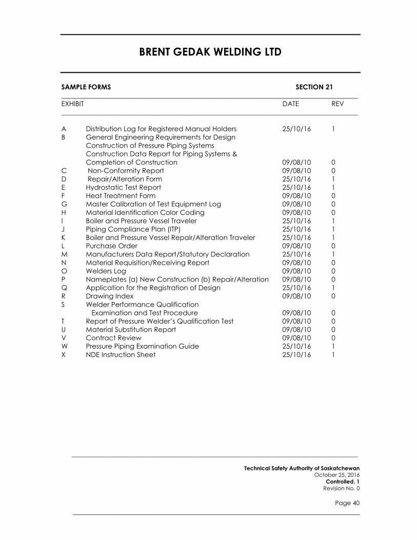
BRENT GEDAK WELDING LTD
____________________________________________________________________________________
Technical Safety Authority of Saskatchewan
October 25, 2016
Controlled. 1
Revision No. 0
Page 40
______________________________________________________________________
SAMPLE FORMS SECTION 21
_______________________________________________________________________________________ EXHIBIT DATE REV
_______________________________________________________________________________________
A Distribution Log for Registered Manual Holders 25/10/16 1
B General Engineering Requirements for Design
Construction of Pressure Piping Systems
Construction Data Report for Piping Systems &
Completion of Construction 09/08/10 0
C Non-Conformity Report 09/08/10 0
D Repair/Alteration Form 25/10/16 1
E Hydrostatic Test Report 25/10/16 1
F Heat Treatment Form 09/08/10 0
G Master Calibration of Test Equipment Log 09/08/10 0
H Material Identification Color Coding 09/08/10 0
I Boiler and Pressure Vessel Traveler 25/10/16 1
J Piping Compliance Plan (ITP) 25/10/16 1
K Boiler and Pressure Vessel Repair/Alteration Traveler 25/10/16 1
L Purchase Order 09/08/10 0
M Manufacturers Data Report/Statutory Declaration 25/10/16 1
N Material Requisition/Receiving Report 09/08/10 0
O Welders Log 09/08/10 0
P Nameplates (a) New Construction (b) Repair/Alteration 09/08/10 0
Q Application for the Registration of Design 25/10/16 1
R Drawing Index 09/08/10 0
S Welder Performance Qualification
Examination and Test Procedure 09/08/10 0
T Report of Pressure Welder’s Qualification Test 09/08/10 0
U Material Substitution Report 09/08/10 0
V Contract Review 09/08/10 0
W Pressure Piping Examination Guide 25/10/16 1
X NDE Instruction Sheet 25/10/16 1
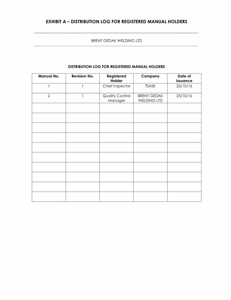
EXHIBIT A – DISTRIBUTION LOG FOR REGISTERED MANUAL HOLDERS
_______________________________________________________________________________________
BRENT GEDAK WELDING LTD ____________________________________________________________________________________________________________
DISTRIBUTION LOG FOR REGISTERED MANUAL HOLDERS
Manual No. Revision No. Registered
Holder
Company Date of
Issuance
1 1 Chief Inspector TSASK 25/10/16
2 1 Quality Control
Manager
BRENT GEDAK
WELDING LTD
25/10/16
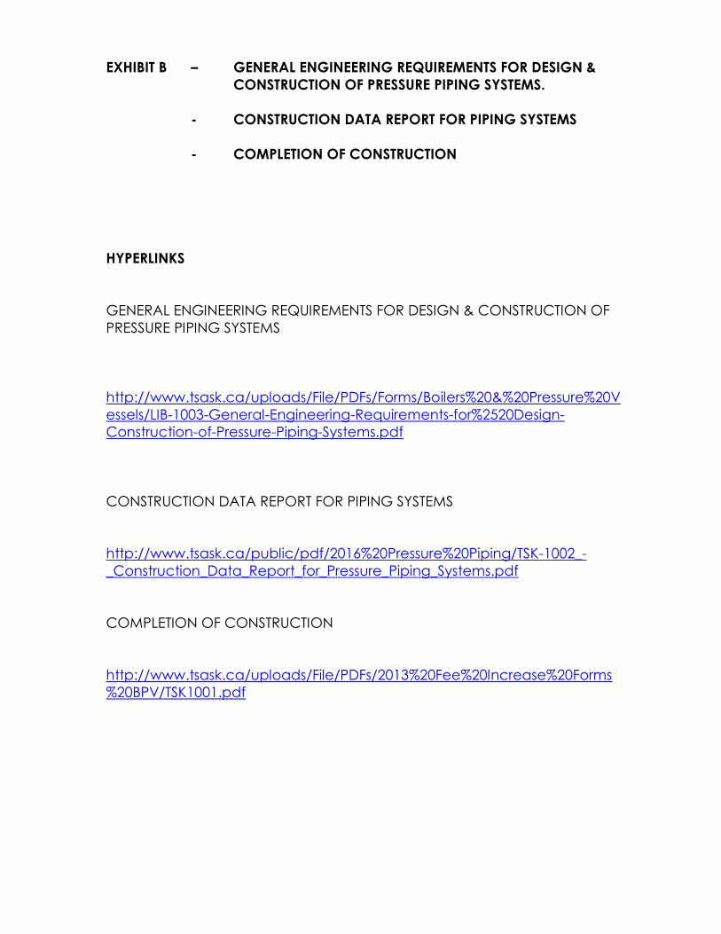
EXHIBIT B – GENERAL ENGINEERING REQUIREMENTS FOR DESIGN &
CONSTRUCTION OF PRESSURE PIPING SYSTEMS.
- CONSTRUCTION DATA REPORT FOR PIPING SYSTEMS
- COMPLETION OF CONSTRUCTION
HYPERLINKS
GENERAL ENGINEERING REQUIREMENTS FOR DESIGN & CONSTRUCTION OF
PRESSURE PIPING SYSTEMS
http://www.tsask.ca/uploads/File/PDFs/Forms/Boilers%20&%20Pressure%20V
essels/LIB-1003-General-Engineering-Requirements-for%2520Design-
Construction-of-Pressure-Piping-Systems.pdf
CONSTRUCTION DATA REPORT FOR PIPING SYSTEMS
http://www.tsask.ca/public/pdf/2016%20Pressure%20Piping/TSK-1002_-
_Construction_Data_Report_for_Pressure_Piping_Systems.pdf
COMPLETION OF CONSTRUCTION
http://www.tsask.ca/uploads/File/PDFs/2013%20Fee%20Increase%20Forms
%20BPV/TSK1001.pdf

Exhibit C – Nonconformity Report
BRENT GEDAK WELDING LTD _____________________________________________________________________________________________________________
Quality System Nonconformance Report NCR Log # ___________
Location: ____________________________ ________________________ Date: _________________________
Quality Program # ___________________________ Job Reference: __________________________________
Description of Item/Equipment: __________________________________________________________________
_________________________________________________________________________________________________
Description of Nonconformance: ________________________________________________________________
_________________________________________________________________________________________________
_________________________________________________________________________________________________
_________________________________________________________________________________________________
_________________________________________________________________________________________________
Proposed disposition: ____________________________________________________________________________
_________________________________________________________________________________________________
_________________________________________________________________________________________________
_________________________________________________________________________________________________
_________________________________________________________________________________________________
Action to prevent reoccurrence: _________________________________________________________________
_________________________________________________________________________________________________
_________________________________________________________________________________________________
_________________________________________________________________________________________________
Acceptance Signatures
NCR Initiator: _______________________________________ Date: _________________________________
Inspector: __________________________________________ Date: _________________________________
Authorized Inspector: _______________________________ Date: _________________________________
Resolution or Rework:
__________________________________________________________________Date: __________________________
__________________________________________________________________________________________________
Resolution/Rework Signatures:
Q.C. Representative: __________________________________ Date: _______________________________
Inspector: ___________________________________________ Date: _______________________________
Authorized Inspector: __________________________________ Date: _______________________________

Exhibit D – REPAIR/ALTERATION FORM
HYPERLINK
REPAIR AND ALTERATION FORM
http://www.tsask.ca/public/images/20142015_Forms/TSK1009_Repair-
Alteration.pdf

EXHIBIT E – HYDROTEST REPORT FORM ______________________________________________________________________________________
BRENT GEDAK WELDING LTD _____________________________________________________________________________________________________________
JOB #: TEST PRESSURE REQUIRED:
TIME HELD: AMBIENT TEMP:
PERFORMED/ WITNESSED BY: DATE:
AUTHORIZED INSPECTOR:
GAUGE #1:
GAUGE #2:
CHART RECORDER: Test: ACCEPT REJECT
COMMENTS:
TIME GAUGE 1 GAUGE 2 CHART REMARKS
QUALITY CONTROL MANAGER: ___________________________ Date: ________________
AUTHORIZED INSPECTOR: _________________________________ Date: ________________
OWNERS INSPECTOR: ____________________________________ Date: ________________
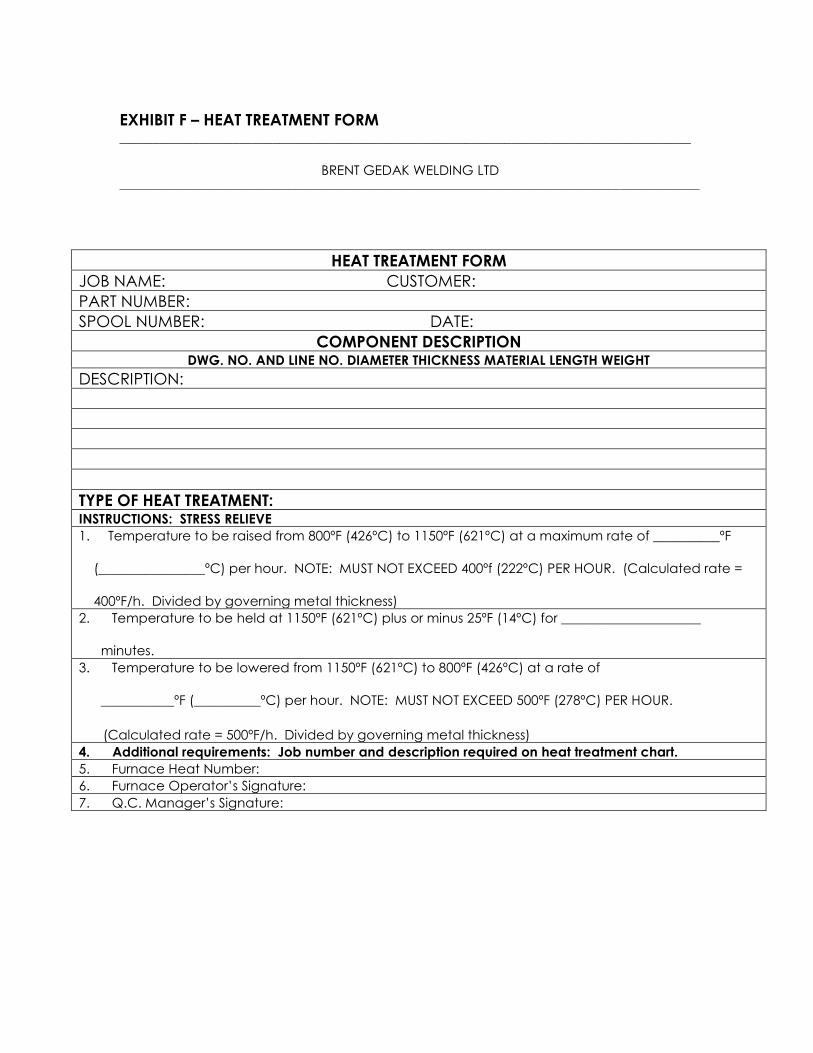
EXHIBIT F – HEAT TREATMENT FORM ______________________________________________________________________________________
BRENT GEDAK WELDING LTD _____________________________________________________________________________________________________________
HEAT TREATMENT FORM
JOB NAME: CUSTOMER:
PART NUMBER:
SPOOL NUMBER: DATE:
COMPONENT DESCRIPTION DWG. NO. AND LINE NO. DIAMETER THICKNESS MATERIAL LENGTH WEIGHT
DESCRIPTION:
TYPE OF HEAT TREATMENT: INSTRUCTIONS: STRESS RELIEVE
1. Temperature to be raised from 800ºF (426ºC) to 1150ºF (621ºC) at a maximum rate of __________ºF
(________________ºC) per hour. NOTE: MUST NOT EXCEED 400ºf (222ºC) PER HOUR. (Calculated rate =
400ºF/h. Divided by governing metal thickness)
2. Temperature to be held at 1150ºF (621ºC) plus or minus 25ºF (14ºC) for _____________________
minutes.
3. Temperature to be lowered from 1150ºF (621ºC) to 800ºF (426ºC) at a rate of
___________ºF (__________ºC) per hour. NOTE: MUST NOT EXCEED 500ºF (278ºC) PER HOUR.
(Calculated rate = 500ºF/h. Divided by governing metal thickness)
4. Additional requirements: Job number and description required on heat treatment chart.
5. Furnace Heat Number:
6. Furnace Operator’s Signature:
7. Q.C. Manager’s Signature:

EXHIBIT G – MASTER CALIBRATION OF TEST EQUIPMENT LOG
_______________________________________________________________________________________
BRENT GEDAK WELDING LTD _____________________________________________________________________________________________________________
MASTER CALIBRATION OF TEST EQUIPMENT LOG
EQUIPMENT
NUMBER
EQUIPMENT
SERIAL NUMBER
DESCRIPTION OF EQUIPMENT &
TEST PERFORMED
DATE
APPROVAL

EXHIBIT H – MATERIAL IDENTIFICATION COLOR CODING
_______________________________________________________________________________________
BRENT GEDAK WELDING LTD _____________________________________________________________________________________________________________
MATERIAL IDENTIFICATION COLOR CODING
DESIGNATION
MATERIAL
COLOUR CODE
SA-234-WPB Carbon Steel Fittings Lt Blue
SA-106-B Carbon Steel Pipe Lt Blue
SA- 105 Carbon Steel Fittings Lt Blue
SA-420-WPL6 L/T Carbon Steel Fittings Yellow
SA-333-6 L/T Carbon Steel Pipe Yellow
SA-350-LF2 L/T Carbon Steel Flanges Yellow
SA-234-WP11 1-1/4 Chrome Fittings Orange
SA-335-P11 1-1/4 Chrome Pipe Orange
SA-234-WP22 2-1/4 Chrome Fittings Brown
SA-335-P22 2-1/4 Chrome Fittings Brown
SA-234-WP5 5 Chrome Fittings Green
SA-335-P5 5 Chrome Pipe Green
SA-234-WP9 9 Chrome Fittings Red
SA-335-P9 9 Chrome Pipe Red
SA-336 Stainless Steel Forgings Black
SA-182 Stainless Steel Fittings Black
SA-312 Stainless Steel Pipe Black
NOTE: All color coded piping, tubing or fittings are identified by a continuous,
longitudinal stripe the entire length of the piping, tubing or fitting. All other pressure
pipe must be marked by stencil, and the markings transferred at the time the pipe
is cut.

EXHIBIT I – BOILER AND PRESSURE VESSEL TRAVELER _______________________________________________________________________________________
BRENT GEDAK WELDING LTD
_______________________________________________________________________________________
SEQ
ITEM
COMMENTS
Q.C.I.
DATE
A.I. HOLD
POINTS
A.I.
DATE
OWNER
DATE
1. Calculations in
File.
2. Release of Approved
Drawing.
3.
AI
Notified
Date:
4.
Heat Numbers
Recorded.
5.
MTRs
Checked.
6.
WPS(s)
Checked.
7.
Welder(s)
Qualified.
8.
Thicknesses Verified
and Recorded.
9.
Nozzle & Flange
Rating Checked.
10.
Nozzle
Orientation.
11.
Nozzles & Fittings
Fit-Up Inspection
12.
Shell(s) & Head(s)
Fit-Up Inspection.
13.
Final Internal
Inspection
Shell Side:
Tube Side:
14.
Weld Sizes
Checked.
15.
Welder I.D.
Checked.
16.
Final External
Inspection.
17.
Radiography. __________%
18.
Other N.D.E.
MT UT LPI
19.
Impact
Tests.
20.
Final Ext. Prior to
P.W.H.T.
21.
PWHT Chart
Checked.
22.
Hydrostatic
Test.
Gauge #1:
Gauge #2:
23.
CRN
Drawing.
24.
N.C.R.’ s
Closed.
25.
Nameplate
Stamping.
26.
Manuf. Data Report
Completed,Verified.
27.
Nameplate
Installation.
28.
The Authorized Inspector shall be presented with the Travel Sheet prior to construction so that he can
designate additional inspection points and/or Hold Points. Any revisions shall be marked with a delta
symbol with revision number and described at the bottom of this page.
*Denotes an A.I. Inspection Point ** Denotes an A.I. Hold Point
Vessel Type: Job No:
Serial No: CRN:
Drawing No: Drawing Revision No:
Travel Sheet Revision No: Travel Sheet Initiation By:

EXHIBIT J – PIPING COMPLIANCE PLAN
_______________________________________________________________________________________
BRENT GEDAK WELDING LTD
_____________________________________________________________________________________________________________
SURVEILLANCE
ACTIVITY
REQUIRED
I & TP REQUIREMENTS
BGW LTD.
CUSTOMER SIGN
OFF YES NO H W V E A SIGN DATE SIGN DATE
Tender Contract Reviewed
Drawings Released
Drawings Submitted to
TSASK for Systems
Exceeding 0.5 Cubic Meters.
I&TP Requirements from
Customer
Welding Procedure Approved
Welding Personnel
Qualified
Materials & MTRs Checked
Visual Weld Inspection
Radiography & Other NDE
Post Weld Heat Treatment
NDE & Heat Treatment Recorded
Non-Conformances
Cleared
Deficiencies Cleared
Hydrostatic Test Gauges
Checked
Hydrostatic Test Complete
Construction Data Report Complete
Completion of
Construction to TSASK for
System Exceeding .5 Cubic Metres
Spools Identified
Special Treatment
(Sandblasting)
Pipe Painting
“As Build” Drawings
Accepted by Owner
H-Hold W-Witness V-Verify E-Examine A-Acceptance by Customer QA or Engineering
FINAL INSPECTION DECLARATION
I, the undersigned, declare the piping system described in the Piping Compliance Plan complies in all respects with the
Regulations for construction, installation, testing and inspection.
____________________________________ ________________________________ ___________________________
Quality Control Manager Print Name Date
____________________________________ ________________________________ ___________________________
Quality Control Representative Print Name Date
Project/Job Name and Description:
Project/Job Type: New Piping Repair, Alteration or Modification to Existing Piping
Job No.:
Customer’s Representative:

EXHIBIT K – BOILER AND PRESSURE VESSEL REPAIR/ ALTERATION TRAVELER _______________________________________________________________________________________
BRENT GEDAK WELDING LTD
______________________________________________________________________________________
The Authorized Inspector shall be presented with the Travel Sheet prior to repair/ alteration construction so
that he can designate additional inspection points and/or Hold Points. Any revisions shall be marked with a
delta symbol with revision number and described at the bottom of this page.
*Denotes an A.I. Inspection Point ** Denotes an A.I. Hold Point
Company: Location:
Job No: Vessel Type:
Serial No: CRN:
Travel Sheet Revision No: Travel Sheet Initiation By:
SEQ
ITEM
COMMENTS
Q.C.M./ Q.C.R.
DATE
A.I. HOLD
POINTS
A.I.
DATE
OWNER
DATE
1. Repair Procedure
approved.
2. Release of Approved
Drawing/ CRN.
3.
Manuf. Data Report
Verified.
4.
AI
Notified.
Date:
5.
WPS(s)
Checked.
6.
Welder(s)
Qualified.
7.
Thicknesses Verified
and Recorded.
8.
MTRs
Checked.
9.
Heat Numbers
Recorded.
10.
Hydrogen
Bakeout
Temp
Time
11.
Nozzle & Flange
Rating Checked.
12.
Nozzle
Orientation.
13.
Nozzles & Fittings
Fit-Up Inspection.
14.
Shell(s) & Head(s)
Fit-Up Inspection.
15.
Internals
Checked.
16.
Final Internal
Inspection
Shell Side:
Tube Side:
17.
Final External
Inspection.
18.
Weld Sizes
Checked.
19.
Radiography. ________ %
20.
Other N.D.E.
MT UT LPI
21.
Impact
Tests.
22.
Final Ext. Prior to
P.W.H.T.
23.
PWHT Chart
Checked.
24.
Hydrostatic
Test.
Gauge #1:
Gauge #2:
25.
N.C.R.’S
Closed.
26.
Nameplate
Installation.
27.
Repair/ Alteration
Report completed
28.
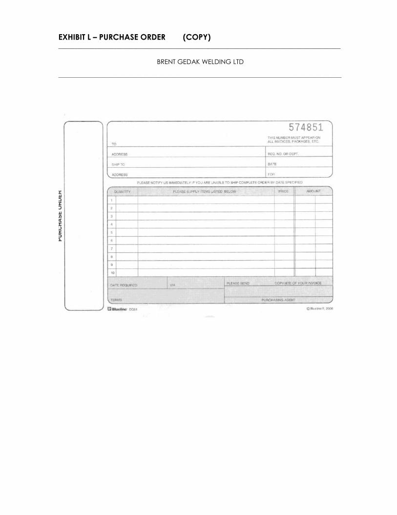
EXHIBIT L – PURCHASE ORDER (COPY) _______________________________________________________________________________________
BRENT GEDAK WELDING LTD
_____________________________________________________________________________________________________________

EXHIBIT M – MANUFACTURERS DATA REPORT/ STATUTORY DECLARATION
MANUFACTURER’S DATA REPORT FOR PRESSURE VESSELS
HYPERLINK
MANUFACTURERS DATA REPORT
http://www.tsask.ca/uploads/File/PDFs/Forms/Boilers%20&%20Pressure%20V
essels/NEW%20FORMS/2014/TSK-
1005%20Manufacture's%20Data%20Report%20for%20Pressure%20Vessles.pd
f
STATUTORY DECLARATION
HYPERLINK
STATUTORY DECLARATION
http://www.tsask.ca/uploads/File/PDFs/2013%20Fee%20Increase%20Forms
%20BPV/TSK1008%20Statutory%20Declaration-Oct29.pdf

Exhibit N – Material Requisition and Receiving Report
BRENT GEDAK WELDING LTD
Job Name: __________________________________________________ □ BRENT GEDAK WELDING LTD Supplied Material
Location: ____________________________________________________ □ Client Supplied Material
Quality Control Manager: _____________________________________ Date: __________________________________
Order
Date
Quantity
Description & Specification
Heat Number
Date Received
MTR Received
Initial

EXHIBIT O – WELDER’S LOG _______________________________________________________________________________________________________________________________
BRENT GEDAK WELDING LTD _______________________________________________________________________________________________________________________________________________________________
WELDER’S LOG
Welder’s Name
Symbol
Process
WPS
Qualified
“P” #
“F” #
Position
Thickness
Range
<6 month Continuity
(as per QW- 322)
Expiry

Exhibit P – NAMEPLATES
Exhibit P (a) – PRESSURE VESSEL NAMEPLATE
(as per ASME VIII, Div. 1, Fig. UG- 118)
Exhibit P (b) – REPAIR/ALTERATION NAMEPLATE
Exhibit P (b) - REPAIR/ ALTERATION NAMEPLATE
(as per ASME VIII, Div. 1, Fig. UG- 118)
REPAIR/ALTERATION BY
BRENT GEDAK WELDING LTD
SERIAL NO: _____________ CRN: _____________________
MDMT: ________________◦F at _________________________p.s.i.
MAWP: _______________p.s.i. at __________________________◦F
DATE: ___________________ TEST PRES: ________________
CERTIFIED BY
BRENT GEDAK WELDING LTD
SERIAL NO: _____________ CRN: _____________________
MAWP: _______________ p.s.i. at __________________________◦F
MDMT: ________________◦F at _________________________p.s.i.
DATE: __________________ TEST PRES: _______________ p.s.i.
________________

EXHIBIT Q – APPLICATION FOR THE REGISTRATION OF DESIGN
APPLICATION FOR THE REGISTRATION OF DESIGN
HYPERLINK
APPLICATION FOR THE REGISTRATION OF DESIGN
http://www.tsask.ca/public/images/TSK-1010_-
_2016_BPV_Design_Registration_-_FINAL.pdf

EXHIBIT R- DRAWING INDEX
_______________________________________________________________________________________
BRENT GEDAK WELDING LTD
_____________________________________________________________________________________________________________
Drawing Number Rev.
No.
Drawing
Title
Date
Issued
Copies
To
QCM
Copies
to QCR
Copies
to Purch.
Mgr.
Copies
to Eng.
File
Copies
to
SBB
Copies To
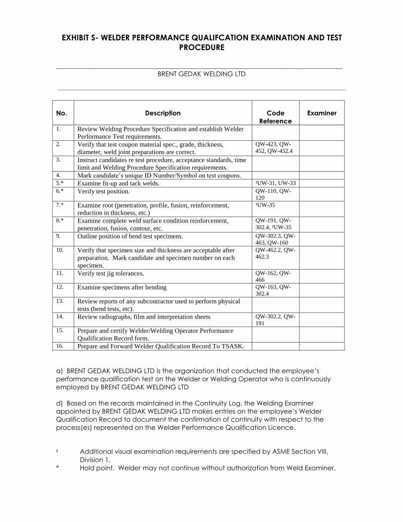
EXHIBIT S- WELDER PERFORMANCE QUALIFCATION EXAMINATION AND TEST
PROCEDURE
_______________________________________________________________________________________
BRENT GEDAK WELDING LTD
_____________________________________________________________________________________________________________
No.
Description
Code
Reference
Examiner
1. Review Welding Procedure Specification and establish Welder
Performance Test requirements.
2. Verify that test coupon material spec., grade, thickness,
diameter, weld joint preparations are correct.
QW-423, QW-
452, QW-452.4
3. Instruct candidates re test procedure, acceptance standards, time
limit and Welding Procedure Specification requirements.
4. Mark candidate’s unique ID Number/Symbol on test coupons.
5.* Examine fit-up and tack welds. ¹UW-31, UW-33
6.* Verify test position. QW-110, QW-
120
7.* Examine root (penetration, profile, fusion, reinforcement,
reduction in thickness, etc.)
¹UW-35
8.* Examine complete weld surface condition reinforcement,
penetration, fusion, contour, etc.
QW-191, QW-
302.4, ¹UW-35
9. Outline position of bend test specimens. QW-302.3, QW-
463, QW-160
10. Verify that specimen size and thickness are acceptable after
preparation. Mark candidate and specimen number on each
specimen.
QW-462.2, QW-
462.3
11. Verify test jig tolerances. QW-162, QW-
466
12. Examine specimens after bending QW-163, QW-
302.4
13. Review reports of any subcontractor used to perform physical
tests (bend tests, etc).
14. Review radiographs, film and interpretation sheets QW-302.2, QW-
191
15. Prepare and certify Welder/Welding Operator Performance
Qualification Record form.
16. Prepare and Forward Welder Qualification Record To TSASK.
a) BRENT GEDAK WELDING LTD is the organization that conducted the employee’s
performance qualification test on the Welder or Welding Operator who is continuously
employed by BRENT GEDAK WELDING LTD
d) Based on the records maintained in the Continuity Log, the Welding Examiner
appointed by BRENT GEDAK WELDING LTD makes entries on the employee’s Welder
Qualification Record to document the confirmation of continuity with respect to the
process(es) represented on the Welder Performance Qualification Licence.
¹ Additional visual examination requirements are specified by ASME Section VIII,
Division 1.
* Hold point. Welder may not continue without authorization from Weld Examiner.
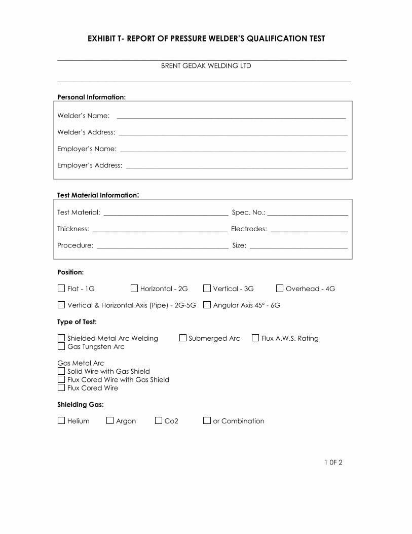
EXHIBIT T- REPORT OF PRESSURE WELDER’S QUALIFICATION TEST
______________________________________________________________________________________
BRENT GEDAK WELDING LTD
_____________________________________________________________________________________________________________ Personal Information:
Welder’s Name: ____________________________________________________________________
Welder’s Address: ____________________________________________________________________
Employer’s Name: ___________________________________________________________________
Employer’s Address: __________________________________________________________________
Test Material Information:
Test Material: _____________________________________ Spec. No.: ________________________
Thickness: ________________________________________ Electrodes: _______________________
Procedure: _______________________________________ Size: _____________________________
Position:
Flat - 1G Horizontal - 2G Vertical - 3G Overhead - 4G
Vertical & Horizontal Axis (Pipe) - 2G-5G Angular Axis 45º - 6G
Type of Test:
Shielded Metal Arc Welding Submerged Arc Flux A.W.S. Rating
Gas Tungsten Arc
Gas Metal Arc
Solid Wire with Gas Shield
Flux Cored Wire with Gas Shield
Flux Cored Wire
Shielding Gas:
Helium Argon Co2 or Combination
1 0F 2

Type of Weld:
Single Butt Weld Double Butt Weld Fillet Weld Backing Strip
Method of Testing:
Face and Root Bend Side Bend X-Ray
Test Results:
PASSED
FAILED
Inspector’s Remarks:
Cracks Gas Inclusion Slag Inclusion Undercut Marks
Lack Penetration
Welder Name: _____________________________ Signature: _______________________________
Process(es): _________ __________ Material (P. No. ): ________
Filler Metal Min. Pipe Diameter: ________mm
Group (F.No. ): _________ __________
Max. Deposited Position(s) Qualified: ________
Weld Metal Th. _________ __________ mm
Backing Req’d: Yes/ No Yes/ No Uphand / Downhand
Symbol: _________
RESTRICTIONS: _______________________________________________________________________
INSPECTOR: __________________________________________________________________________
Test Date: _______________________________ Expiry Date: _______________________________
2 of 2

Exhibit U – MATERIAL SUBSTITUTION REPORT
BRENT GEDAK WELDING LTD _____________________________________________________________________________________________________________
Material Substitution Report
Location: ____________________________ ________________________ Date: _________________________
Quality Program # ___________________________ Job Reference: __________________________________
Description of Item/Equipment: __________________________________________________________________
_________________________________________________________________________________________________
Description of parent material: ___________________________________________________________________
_________________________________________________________________________________________________
_________________________________________________________________________________________________
_________________________________________________________________________________________________
_________________________________________________________________________________________________
Proposed material change: ______________________________________________________________________
_________________________________________________________________________________________________
_________________________________________________________________________________________________
_________________________________________________________________________________________________
_________________________________________________________________________________________________
Reason for material change: _____________________________________________________________________
_________________________________________________________________________________________________
_________________________________________________________________________________________________
_________________________________________________________________________________________________
Acceptance Signatures
Owner’s Representative: ____________________________ Date: ________________________________
QC Manager: ______________________________________ Date: ________________________________
Authorized Inspector: _______________________________ Date: _________________________________
Resolution or Rework Criteria:
__________________________________________________________________Date: __________________________
__________________________________________________________________________________________________
__________________________________________________________________________________________________

Exhibit V – CONTRACT REVIEW
BRENT GEDAK WELDING LTD _____________________________________________________________________________________________________________
Job Number:__________________ Date:
Owner Company: __________________________________
Location: ________________________________________
Description of job: _____________________________________________
____________________________________________________________
RESPONSIBLE FOR QUALITY
CONTROL FUNCTIONS
OWNER CONTRACTOR
Materials Receiving Inspection
Materials
Welder Supervision
Welders Records
Site Control of NDE
Witness of Pressure Tests
Preparing Quality Control Records
Heat Treatment
Design Submissions
Drawings
As Builts
Under TSASK Design and Construction Regulations, any Owner/Subcontractor who
assumes responsibility for any quality control function must have their own Authorized
Quality Control Program for performing these functions.
Code of construction: ASME B31.1 _______ B31.3_______ Fluid service category.____
Other: _________________________ CSA Z662 Fabrication:_____________________
Owner’s Representative_________________
Date Contracted:
QC Manager Date
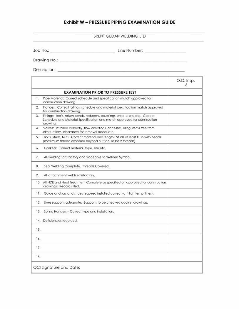
Exhibit W – PRESSURE PIPING EXAMINATION GUIDE
_________________________________________________________________________ BRENT GEDAK WELDING LTD
_____________________________________________________________________________________________________________ Job No.: _________________________________ Line Number: _____________________
Drawing No.: _________________________________________________________________
Description: _________________________________________________________________
Q.C. Insp.
√
EXAMINATION PRIOR TO PRESSURE TEST
1. Pipe Material: Correct schedule and specification match approved for
construction drawing.
2. Flanges: Correct ratings, schedule and material specification match approved
for construction drawing.
3. Fittings: tee’s, return bends, reducers, couplings, weld-o-lets, etc. Correct
Schedule and Material Specification and match approved for construction
drawing.
4. Valves: Installed correctly, flow directions, accesses, rising stems free from
obstructions, clearance for removal adequate.
5. Bolts, Studs, Nuts: Correct material and length. Studs at least flush with heads
(maximum thread exposure beyond nut should be 2 threads).
6. Gaskets: Correct material, type, size etc.
7. All welding satisfactory and traceable to Welders Symbol.
8. Seal Welding Complete. Threads Covered.
9. All attachment welds satisfactory.
10. All NDE and Heat Treatment Complete as specified on approved for construction
drawings. Records filed.
11. Guide anchors and shoes required installed correctly. (High temp. lines).
12. Lines supports adequate. Supports to be checked against drawings.
13. Spring Hangers – Correct type and installation.
14. Deficiencies recorded.
15.
16.
17.
18.
QCI Signature and Date:
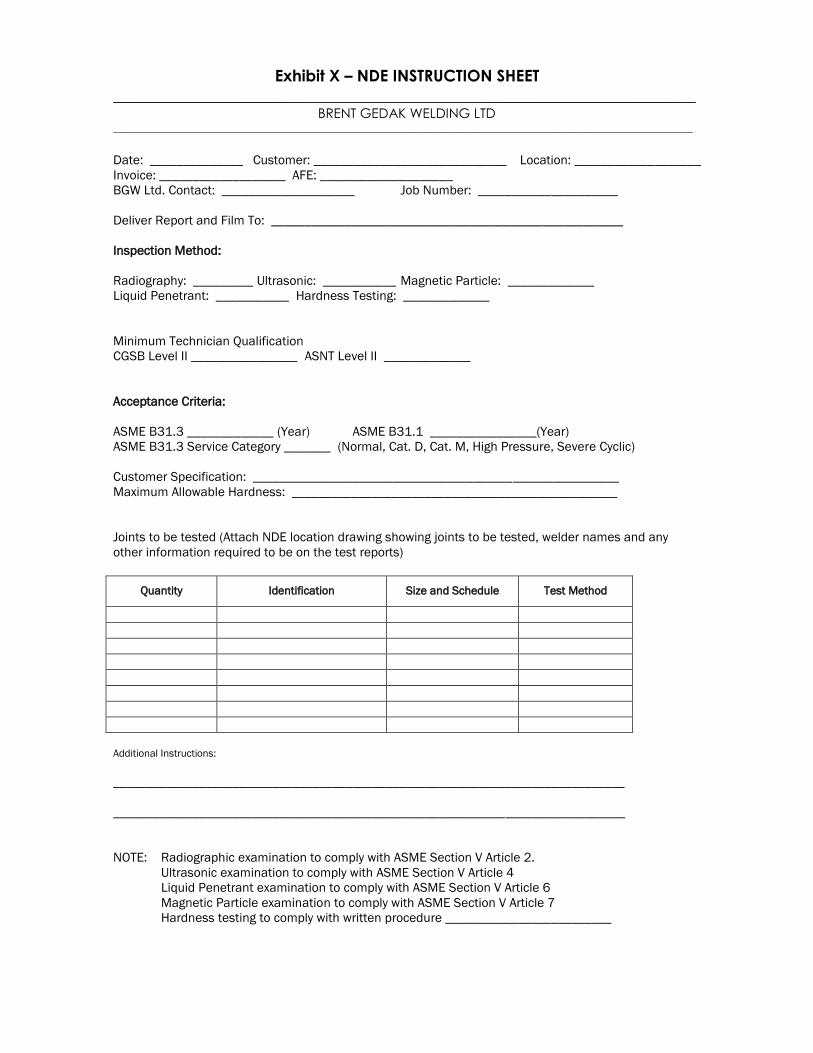
Exhibit X – NDE INSTRUCTION SHEET
_________________________________________________________________________ BRENT GEDAK WELDING LTD
_____________________________________________________________________________________________________________
Date: ______________ Customer: _____________________________ Location: ___________________
Invoice: ___________________ AFE: ____________________
BGW Ltd. Contact: ____________________ Job Number: _____________________
Deliver Report and Film To: _____________________________________________________
Inspection Method:
Radiography: _________ Ultrasonic: ___________ Magnetic Particle: _____________
Liquid Penetrant: ___________ Hardness Testing: _____________
Minimum Technician Qualification
CGSB Level II ________________ ASNT Level II _____________
Acceptance Criteria:
ASME B31.3 _____________ (Year) ASME B31.1 ________________(Year)
ASME B31.3 Service Category _______ (Normal, Cat. D, Cat. M, High Pressure, Severe Cyclic)
Customer Specification: _______________________________________________________
Maximum Allowable Hardness: _________________________________________________
Joints to be tested (Attach NDE location drawing showing joints to be tested, welder names and any
other information required to be on the test reports)
Quantity Identification Size and Schedule Test Method
Additional Instructions:
_____________________________________________________________________________
_____________________________________________________________________________
NOTE: Radiographic examination to comply with ASME Section V Article 2.
Ultrasonic examination to comply with ASME Section V Article 4
Liquid Penetrant examination to comply with ASME Section V Article 6
Magnetic Particle examination to comply with ASME Section V Article 7
Hardness testing to comply with written procedure _________________________