quadrilateral perspective · page 150 – excerpt from the book “a perspectiva dos...
TRANSCRIPT


_______________________________________________________________________________________________Quadrilateral Perspective - Yvonne Tessuto Tavares - www.perspectivaquadrilatera.net
1
QUADRILATERAL PERSPECTIVE
NEW EXACT PERSPECTIVE MEASURED IN MILLIMETERS
Yvonne Tessuto Tavares

_______________________________________________________________________________________________Quadrilateral Perspective - Yvonne Tessuto Tavares - www.perspectivaquadrilatera.net
2
TRADITIONAL PERSPECTIVE
In the text below, the Architect and Architecture Course Professor at Pernambuco Federal University explains briefly and realistically the difficulties faced with the traditional perspective by conic projection.
“AND HOW ABOUT THE FUTURE”?
“The conic perspective has several inconveniences: the static view point, the lateral deformation, the parallelism of the verticals and the small visual angle. The two latter can be partially corrected by using an inclined square, but this is exhausting when we have to draw on a drawing board. We may use a graphic computer to overcome this inconvenience … but this is hardly accessible.
Assuming that we accept the recent theories about vision and brain functioning, we would be inclined to the adoption of the following new foundations: the view point (eye) moves itself, travels all over the objects (like television) in successive lines and points that are located and focused. A complete image is formed in the brain, a sum of many partial images. Since each image has its own visual angle, the angular openings will be defined by arches and not by straight lines. (It is not by chance that this idea coincides with the Universe structure modern theory!) And the arches should be represented on a spherical surface. The same happens in Photography with the big angular lens “fish eye” type.
The Spherical Perspective theory is not more complicated than the Conic Perspective theory which we have just studied. However, the spherical perspective representation is not handy, it is not adequate to the traditional instruments: ruler, squares and compass.
The graphic computer overcame this inadequacy. Therefore, the scholars have a vast field ahead”.
Page 150 – excerpt from the book “A PERSPECTIVA DOS PROFISSIONAIS”, by Gildo A. Montenegro – 1983 – Editora Edgard Blucher Ltda. (Free translation)

_______________________________________________________________________________________________Quadrilateral Perspective - Yvonne Tessuto Tavares - www.perspectivaquadrilatera.net
3
THE FUTURE STARTS HERE
I am introducing a new rationale that frees the three-dimensional space in drawing and solves several problems relative to the traditional perspective.
According to this new system, the spherical perspective (Integrated Perspective) will be drawn with ruler and squares, with both the environment and the objects dimensions drawn in it.
In view of the image satisfactory results and considering the elimination of problems involving the making of, Yvonne Tessuto Tavares’s Quadrilateral Perspective can be considered a real breakthrough in the exact perspective and a new system of plane projection.

THE POINT (Meditation)
One day, I caught a glimpse of a small black point ahead of me, very far away… there, on the horizon. Staring at it I noticed that although only a point, it was magnificent and a perfect hiding place for an unsolved, unnoticed mystery. I could see the point smiling and I thought to myself that if it smiled, it could not be mean or wild. Thus, I tried to get better acquainted with it, to improve our relationship. We chatted… I soon realized that the point knew me very well. It made fun of my ignorance, of my scarce knowledge. And so we spent three long years. The point refused to reveal itself; it gave me only hints that led me nowhere. It made fun of me, of my great and unreal passion.
Worn out, feeling distant and isolated from my daily routine, from the real facts that vibrated around me, I was nearly giving up this mad obstinacy of unveiling the secret closely guarded by the mysterious point. Then, one day, when I was preparing myself to take a stroll after my meal, the unexpected revelation of the secret kept by the mysterious point CROSSED my mind: Two overlapping squares as shown below. Then, for one year I dedicated myself to a great concentration work based on the unexpected revelation. And this is how I got at A NEW AND WONDERFUL EXACT PERSPECTIVE TREATISE introducing a new foundation and a new system that free the three-dimensional space on the drawing. The mysterious point I referred to above is simply the so-called distance point existing on the horizontal line of spatial geometry (stereometry). It refers to the depth (one of the dimensions relative to the three-dimensional space).
_______________________________________________________________________________________________Quadrilateral Perspective - Yvonne Tessuto Tavares - www.perspectivaquadrilatera.net
4

_______________________________________________________________________________________________Quadrilateral Perspective - Yvonne Tessuto Tavares - www.perspectivaquadrilatera.net
5
YVONNE TESSUTO TAVARES
QUADRILATERAL PERSPECTIVE
A NEW EXACT PERSPECTIVE MEASURED IN MILLIMETERS
PERSPECTIVES: PARALLEL
OBLIQUE AERIAL PARALLEL
AERIAL OBLIQUE
INTEGRATED
São Paulo - Brazil
1987
_______________________________________________________________________________________________Quadrilateral Perspective - Yvonne Tessuto Tavares - www.perspectivaquadrilatera.net
6

_______________________________________________________________________________________________Quadrilateral Perspective - Yvonne Tessuto Tavares - www.perspectivaquadrilatera.net
7
ACKNOWLEGEMENT, OFFER, DEDICATION
I thank Rubens Nunes Tavares, my husband and friend, for the incentive and help offered during the process of bringing out this book.
I offer this book to my sons, Sergio Nunes Tavares and Mauro Nunes Tavares as well as to my daughter-in-law, Giana Casarotto Tavares.
Dedicated to the memory of Ernesto Tessuto, my father and to the presence of my mother, Rosa Incao Tessuto.

_______________________________________________________________________________________________Quadrilateral Perspective - Yvonne Tessuto Tavares - www.perspectivaquadrilatera.net
8
FOREWORD
Unlike many others, this book does not aim to teach the traditional perspective systems. This book emerged from my years of study and researches in the exact perspective field, in order to solve drawing problems existing in the current systems: impossibility of finding the depth in any height of the horizon line and in any type of perspective. When I solved these problems I was able to free the three-dimensional space in drawing.
The new exact perspective presented herein is based on this new basic concept. Therefore, in addition to the didactic purpose of teaching how to draw in perspective, it embodies the characteristic of a thesis to be supported in the Space Geometry (Stereometry) field.
I kept this work to myself for nearly ten years. Only now the idea of divulging this work as a book occurred to me. A great number of professionals who use the drawing as a form of expression may benefit from this new easy-to-learn perspective system by adopting its use in their works.
The demonstration of the perspective exercises included in this book is developed in an evolutionary process, in such a way that the more you perform the exercises the better you will understand the subject matter. Therefore, one should study the oblique perspective only after thoroughly mastering the parallel perspective study. The aerial oblique and the integrated perspectives should be the last ones to be studied, considering that they require total expertise in performing the several perspective processes.
The several lines and points used in perspective will perform the miracle of extracting from the paper what was previously conceived. First of all, we have to sketch the basic idea, with all the measurements of the elements comprising the project. For instance, if the idea is to make a chair, we should study its style, its shape and write down its measures (height of its back, feet, width, seat depth, etc.). The drawings of the objects as well as the environment measurement in meters should be devised in advance.

_______________________________________________________________________________________________Quadrilateral Perspective - Yvonne Tessuto Tavares - www.perspectivaquadrilatera.net
9
PRESENTATION
In his treatise on painting, dated 1435, Alberti developed the perspective explaining that the light rays reflecting from the object to the eye form a cone. If we intercept this cone using a transparent square at a certain distance from our eyes, we will be able to outline the image of the object observed in it. This central linear perspective studied by Alberti and by the 15th century renaissance painters has a vanishing point to where all the drawing lines referring to the depth converge.
This mechanically performed type of perspective lacks mathematical precision and has not experienced any innovation; therefore, it has not improved throughout the past centuries.
The oblique perspective was a consequence of the architectonic development that occurred in the 20th century. It presents an image seen from a sharp corner, resulting in two opposed lateral vanishing points. It is a conic projection inside a system – Theory of Projections, which is mathematically precise. This type of perspective adapts itself almost totally to architectonic projects, but does not apply to other types of drawings that require a simpler making of but can not do without the mathematical precision. For example, decorators, landscape architects, scenographers, plastic artists, advertising professionals, etc.
The projection of a ground plan, with which the architects work, besides demanding a hard work is almost totally adaptable to building and house façades works (exterior projects).
Sometimes, the difficulties we face in our practice hinder the complete fulfillment of our performance. The documents left by our predecessors and that served as basis for our studies are not always exempt from doubts or questions. When we acquire our knowledge at school, reading books or through professionals, who perform the task right before us, we have to be inquisitive, otherwise there will be no possibility of improving the knowledge relayed.
We will stagnate and so will our professional work.
Every human being has the right to express his ideas and opinions, even under the risk of having them not accepted after being proved and examined.
This fact should not concern learned people, they should be concerned with the alienation and disregard for the novelties introduced by people who believe they are learned.

_______________________________________________________________________________________________Quadrilateral Perspective - Yvonne Tessuto Tavares - www.perspectivaquadrilatera.net
10
It is interesting to notice that sometimes, the creative and innovative solution for a problem lies in a new association of already existing elements.
The new perspective treatise introduced hereby is revolutionary and has a worldwide impact because it was developed based on a NEW BASIC CONCEPT which I had the privilege of finding out by making a new combination of the already existing elements.
This knowledge was “hidden” in books that I randomly bought in the city bookstores. With this knowledge plus the knowledge acquired in the routine skills of the work I managed to give life to imagination and get at the creation of a new exact perspective measured in millimeters.
The fundamental idea occurred to me as a result of my exhaustive search for a way to represent the plane on shortening scale (scorcio), without using the conic projection system to draw the oblique perspective.
The new system of remaking the vertical plane in three dimensions that I discovered has completely solved the perspective problems. The system frees the perspective, therefore, one can draw with mathematical precision in any type of perspective: parallel, oblique and aerial with 1, 2 and 3 vanishing points respectively. It has also allowed the creation of other types of perspective which I called aerial parallel perspective (2 vanishing points) and integrated perspective (5 vanishing points).
I created geometric structures for the perspective types, according to which one can draw anything in millimeters, at any height of the horizon line and with mathematical precision. Without calculations or mathematical formulas, the work is mechanically performed using only lines and several points as inherent to the perspective work.
All drawings, including those of the aerial views are made on open angles, presenting an ample and complete view, as our eyes are used to have in real world.
This new perspective system allows not only to make architectonic drawings but also any other type of drawing. The aspect of the system in millimeters dominates the three measurements relative to the three-dimensional space completely: height, width and length or depth. The latter has always been the perspective great incognito in the current systems.

_______________________________________________________________________________________________Quadrilateral Perspective - Yvonne Tessuto Tavares - www.perspectivaquadrilatera.net
11
INTRODUCTION
Perspective is a device in three-dimensional drawing according to which the objects graphically represented on shortening scale (scorcio) plane give us the same impression of solidity experienced in real vision. It is absolutely essential to the making of artistic and technical designs and used by a great number of professionals who have to express their ideas graphically.
This new perspective system adapts itself to any type of exact perspective or to any type of drawing. It allows the construction of boxes in millimeters in a three-dimensional space; any object, even those with richer details can be drawn inside it.
The new foundation of this exact perspective comprises two overlapped images 17 centimeters apart from each other.
The association of two scientific elements led me to create this new perspective treatise and to the total conquest of space on the drawing.
I will briefly explain the two scientific elements that make up the new perspective basic concept: one is a geometric element and the other refers to the vision.

GEOMETRIC ELEMENT
“Pythagoras proved that the world of sounds is ruled by exact numbers. Therefore, he oriented his research towards checking if the same occurred in the world of visual images. And there is an extraordinary accomplishment here. I look around: here am I in this colorful and wonderful Greek landscape, among natural rustic orphic grottos and the sea. Where, under this beautiful chaos a simple, numeric structure could be found?
The issue sends us back to the most primitive constants of our perceptions of the natural laws. It is evident that in order to find the answer we have to start with the universal data of experience. Our visual world is based on two experiences: gravity is vertical and the horizon is orthogonal to the first one. This association, this crossing of lines in the visual field, fixes the nature of the right angle; thus, if I rotated this sensory right angle (downward direction and both sides direction) in a fourfold pattern, I would be back to the crossing of gravity with the horizon. The right angle is defined by this operation in four stages and through it, differentiated from any other arbitrary angle”. Page 157
“Thus, in the visual world, in the vertical plane image that is presented by our eyes, a right angle is defined by its rotation in four stages over itself. The same definition applies to the horizontal plane perceived, in which, in fact, we move ourselves. Picture this world, the world of the flat earth of the maps and of the cardinal points. I am in it, looking through the straits, from Samos to Asia Minor, on the South direction. I pick up a triangular rod and point it on that direction: South (I intend to illustrate the four successive rotations of the right angle with the triangular rod). By rotating the rod one right angle it will point to the West; one more right angle rotation and it will be pointing to the North; a third one and it will point to the East and the fourth and last rotation it will point to the South, Asia Minor, our starting point.
It is not only the natural world of our perception that obeys these relations; the world constructed by us does the same. It has been like that since the times that the Babylonians constructed the Hanging Gardens and even before, when the Egyptians erected the pyramids. In a practical sense, these cultures were already aware of a square arrangement of construction, in which the numerical relations revealed and formed right angles. The Babylonians knew many of these formulas, maybe hundred of them circa 2000 B.C. The Indians and the Egyptians knew some of them. Apparently, the latter ones used the square arrangement most often as the sides of the triangle made up of three, four or five units. It was only circa 550 B.C. that Pythagoras rescued this knowledge from the world of empiric facts to the universe of that we would call today, the proof”. Page 158
“The right angle is the symmetry element that divides the plane four times. If the flat space presented another type of symmetry, the theorem would not be real; the truth would be in some other relation between the sides of other particular triangles. It should be noted that, like the matter, the space is a fundamental part of the nature, even though invisible (like the air); in this dimension lies the essence of geometry. Symmetry does not represent only a descriptive sophistication; similarly to other Pythagorean thoughts, it seeks the harmony of nature”. Page 161
From the book The Ascent of Man, by J. Bronowski (Excerpt translated from the Portuguese version)
Livraria Martins Fontes Ltda. and Editora Universidade de Brasília Brazilian 1st edition – 1979 The author of this book italicized a few words
_______________________________________________________________________________________________Quadrilateral Perspective - Yvonne Tessuto Tavares - www.perspectivaquadrilatera.net
12

_______________________________________________________________________________________________Quadrilateral Perspective - Yvonne Tessuto Tavares - www.perspectivaquadrilatera.net
13
ELEMENTS ABOUT THE VISION
“Adjustment and focusing: All those whose hobby is photography are very familiar with the camera. The camera has certain devices that allow focusing images at different distances, from a close point to the infinity. The limit depends only on the lens features and on the adjustments that can be made to them. The human eye can also be adjusted to focus close or distant images. The closest point a young person with normal vision can focus with sharpness and clearness is about 17cm away from the viewer. And the remotest, the farthest point is located in the infinity. The infinity is considered the last point that can be naturally seen on the horizon line. There is a space between the closest and the remotest point; in the small lapse of time in which the eye captures the image, the luminous waves responsible for it travel all the way. Meanwhile, the eye accommodates itself to see either closer or farther. This space is called accommodation range. In a person with normal vision or emmetropic, the accommodation range goes from 17cm (close point) to the infinity (remote point).”
“Medicina e Saúde” Vol. 1 - Page 212 - Abril Cultural – 1968

NEW FOUNDATION - NEW SYSTEM The total conquest of space in exact perspective represents the landmark of a new era in the drawing world.
With the discovery of the square on a shortening (scorcio) scale in any type of perspective, the depth is no longer a taboo; hence, one can work the three-dimensional space in millimeters.
Try to do the following test:- Bring your hand close to your eyes and then slowly move it away until ensuring perfect visual sharpness. You will notice that you need a 17-cm space to have a sharp vision.
Therefore, I considered two overlapped images to draw in perspective: one out-of-focus image very close to the eyes and another sharp and well focused image 17cm farther.
According to Pythagoras, the symmetry of the flat space is a square. Therefore, in my opinion, the horizontal flat surface, the visual field, is simply the result of two overlapped squares 17cm apart from each other.
When we focus an image at the closest point, our vision does not reach beyond 2.60m or 2.70m. I considered a 3-m square to facilitate the construction of the drawings.
Remark: The out-of-focus vision is at the right and left side of the viewer.
_______________________________________________________________________________________________Quadrilateral Perspective - Yvonne Tessuto Tavares - www.perspectivaquadrilatera.net
14

_______________________________________________________________________________________________Quadrilateral Perspective - Yvonne Tessuto Tavares - www.perspectivaquadrilatera.net
15
REMARKS
The human eye adjusts itself to focus close or distant images. The closest point that we can precisely and sharply focus is 17cm away from our eyes.
It is important to stress that only the parallel (1 vanishing point) and the oblique (2 vanishing points) perspectives will be worked in this closest point of vision.
The aerial parallel (2 vanishing points), the aerial oblique (3 vanishing points) and the integrated (5 vanishing points) perspectives will be worked in the space existing between the closest point of our vision up to infinity. This space is called accommodation range. The aerial perspectives image are focused very far away, dozens of meters away from our eyes.
The explanatory graphs of these types of perspectives will enable a better understanding of the process.

_______________________________________________________________________________________________Quadrilateral Perspective - Yvonne Tessuto Tavares - www.perspectivaquadrilatera.net
16
PARALLEL PERSPECTIVE (1 VANISHING POINT)
Figure 2 illustrates the focused vision 17cm away from the viewer’s eyes. This is the representation of the three-dimensional space where we will draw the parallel (1 vanishing point) and the oblique (2 vanishing points) perspectives.
The parallel perspective represents the space that can be perceived by our visual organs when we focus the image on the closest point.
The oblique perspective presents the object seen from a sharp corner, within this visual space represented by the parallel perspective.
The out-of-focus vision represented by two 3x3m squares is close to the viewer’s eyes.
The line located at the height of our eyes determines the limits of our vision at the two ends of our out-of-focus vision. These two points transferred to the horizon line (our vision farthest point) will determine the depth points. One point to the right and the other to the left of the viewer.

PARALLEL PERSPECTIVE (1 VANISHING POINT)
ILLUSTRATIVE GRAPH
_______________________________________________________________________________________________Quadrilateral Perspective - Yvonne Tessuto Tavares - www.perspectivaquadrilatera.net
17

_______________________________________________________________________________________________Quadrilateral Perspective - Yvonne Tessuto Tavares - www.perspectivaquadrilatera.net
18
AERIAL PARALLEL PERSPECTIVE (2 VANISHING POINTS)
Figure 3 illustrates the focused vision in the accommodation range (space existing between the closest point of our vision and the infinity, farthest point).
The accommodation range is the line relative to the center of our vision. It goes from the closest point to the farthest (infinity). The support line or line of width measurement is the maximum height the drawing will reach. From this line to the accommodation range line, where the square that indicates the point of the focused vision is placed, we get at the height where the viewer is located.
The distance existing between the viewer’s eye up to the square on the accommodation range line relates to the distance where the viewer of the observed object is located.
The zero level plane represents the drawing base.
The same reasoning applies to the aerial oblique perspective.
The vanishing point 2 of the aerial parallel perspective and the vanishing point 3 of the aerial oblique perspective represent the vanishing height of the solids seen from an elevated distance; for example, when we observe a view from a helicopter.

AERIAL PARALLEL PERSPECTIVE (2 VANISHING POINTS)
ILLUSTRATIVE GRAPH
_______________________________________________________________________________________________Quadrilateral Perspective - Yvonne Tessuto Tavares - www.perspectivaquadrilatera.net
19

_______________________________________________________________________________________________Quadrilateral Perspective - Yvonne Tessuto Tavares - www.perspectivaquadrilatera.net
20
SCALES MOST USED IN PERSPECTIVE DRAWINGS
For interior projects..... 1:10 ....... 1m ..... 10cm ..... 1:20 ....... 1m ..... 5cm
For exterior projects..... 1:50 ....... 1m ..... 2cm
To make aerial perspectives
1:100.... 1m.... 1cm
1:200.... 1m.... 5mm
1:500.... 1m.... 2mm
We have seen that the parallel perspective will have a maximum space of 6m (2 squares) of width by 3m of height. This is the visual field of the parallel perspective. In order to avoid constructing the drawing with the vanishing point at the center of the project, we work with smaller width measured in meters. As a result, the drawing image will be more pleasant.
Sometimes, in an exterior project, like a garden, for example, we need a space larger that 6-m wide. In this case we should use two scales: a larger scale for the environment and a smaller one for the objects to be drawn in it.
Imagine how it is done in the construction of a maquette. Do not forget to construct the horizontal plane (upon which the objects will be drawn), closer to the horizon line, thus avoiding an aerial view.

CONSTRUCTION OF THE SYSTEM 1 — Construct square A drawn to scale. 2 — Calculate the distance of 17cm from the middle of square A base downwards. Determine point a. 3 — In the upward direction, draw a vertical line of 1.70m from bottom to top of point a and mark point b.
4 — Construct a square with the same dimensions of square A on the line constructed between points a and b. See square B in figure 4.
5 — Draw a horizontal line crossing the two squares at point b height.
6 — Draw a diagonal line from point c to point d (see figure 4).
7 — From the vertices of square A, draw lines that vanish in point b.
8 — Determine point f at the intersection of the lines that join points e, b, c and d. 9 — By joining points f and g with a horizontal line we will have a horizontal plane.
NEW BASIC CONCEPT The horizontal plane results from the overlapping of two images 17cm. apart from each other.
_______________________________________________________________________________________________Quadrilateral Perspective - Yvonne Tessuto Tavares - www.perspectivaquadrilatera.net
21

CONSTRUCTION OF THE SYSTEM (cont’d)
The structure above shows the NEW FOUNDATION for the exact perspective, which consists of an overlapping of two images: one out-of-focus image starting at the view point (where the viewer is located), and another clear image 17cm apart from the viewer, on the support line, where we will draw a flat surface that resulted from these two overlapped images.
Therefore:-
Work always with squares measuring 3x3 meters.
Scale: 1:50,
3 meters correspond to............. 6 centimeters
17 centimeters correspond to..... 3,4 millimeters The depth point can be at the right or at the left of the vanishing point.
_______________________________________________________________________________________________Quadrilateral Perspective - Yvonne Tessuto Tavares - www.perspectivaquadrilatera.net
22

_______________________________________________________________________________________________Quadrilateral Perspective - Yvonne Tessuto Tavares - www.perspectivaquadrilatera.net
23

_______________________________________________________________________________________________Quadrilateral Perspective - Yvonne Tessuto Tavares - www.perspectivaquadrilatera.net
24
PARALLEL PERSPECTIVE
(1 VANISHING POINT)

_______________________________________________________________________________________________Quadrilateral Perspective - Yvonne Tessuto Tavares - www.perspectivaquadrilatera.net
25
LOCATION OF THE VANISHING, VIEW AND DEPTH POINTS IN PARALLEL PERSPECTIVE First of all, draw the three parallel and horizontal lines:
— support line
— horizon line
— distance line.
Work to a scale and perform the following operations:
A) — Draw a perfectly geometric square on the support line with the vertical and horizontal lines in parallel.
B) — Locate the vanishing and view points as follows: find the middle of the square and with a vertical line starting at the support line and going up to the horizon line (which is the viewer’s view) you will find where to mark the vanishing point. From the support line, starting at the same vertical line downwards, determine the visual distance of 17cm and locate the view point. Work always to a scale. 17cm is equal to 8.5mm in 1:20 scale.
C) — Now sketch a diagonal within the square, from one vertex to the other. Then, sketch a line parallel to this diagonal; from the view point to the distance line (we do not construct the square out of focus in order to facilitate the process of carrying out the structure). From this point, sketch a perpendicular line up to the horizon line and you will find the depth point. This operation is shown in figure nº 7.
After obtaining the vanishing, view and depth points, you will construct a flat surface to draw in perspective.
Note in figure nº 8 that the distance between the view point and the distance line is always equal to the distance between the vanishing point and the depth point. Therefore, in order to work on parallel perspective it will not be necessary to perform the whole operation shown in figure nº 7 to find the three points. You have only to place the depth point at the horizon line, far from the vanishing point in the same proportion that the view point is located at the distance line.

LOCATION OF THE VANISHING, VIEW AND DEPTH POINTS IN PARALLEL PERSPECTIVE (cont’d)
_______________________________________________________________________________________________
Quadrilateral Perspective - Yvonne Tessuto Tavares - www.perspectivaquadrilatera.net 26

PLANES IN SEVERAL POSITIONS UNDER A SINGLE VIEW POINT IN PARALLEL PERSPECTIVE
After finding the vanishing, view and depth points, sketch any kind of segment on the space. At one of the ends of this segment, sketch a line to thevanishing point and from the other end, sketch a line to the depth point. At the intersection of these lines you will find the depth of each segment. This is how we obtain the respective planes or the squares on a shortening (scorcio) scale. See figure nº 9.
_______________________________________________________________________________________________Quadrilateral Perspective - Yvonne Tessuto Tavares - www.perspectivaquadrilatera.net
27
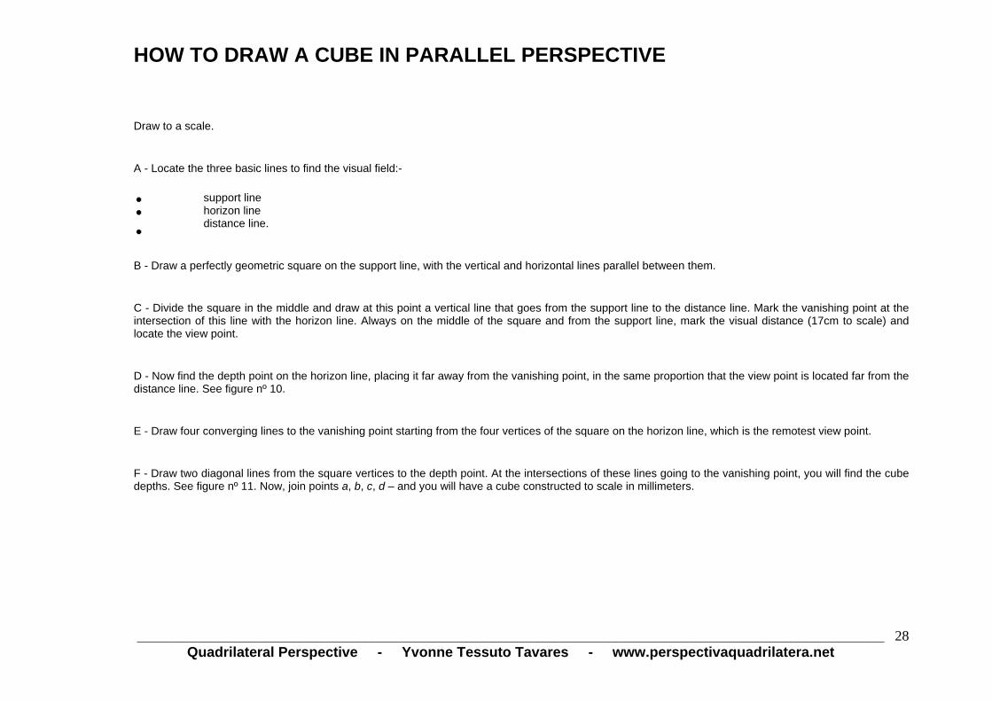
HOW TO DRAW A CUBE IN PARALLEL PERSPECTIVE
Draw to a scale.
A - Locate the three basic lines to find the visual field:-
support line horizon line
distance line.
B - Draw a perfectly geometric square on the support line, with the vertical and horizontal lines parallel between them.
C - Divide the square in the middle and draw at this point a vertical line that goes from the support line to the distance line. Mark the vanishing point at theintersection of this line with the horizon line. Always on the middle of the square and from the support line, mark the visual distance (17cm to scale) and locate the view point.
D - Now find the depth point on the horizon line, placing it far away from the vanishing point, in the same proportion that the view point is located far from thedistance line. See figure nº 10.
E - Draw four converging lines to the vanishing point starting from the four vertices of the square on the horizon line, which is the remotest view point.
F - Draw two diagonal lines from the square vertices to the depth point. At the intersections of these lines going to the vanishing point, you will find the cubedepths. See figure nº 11. Now, join points a, b, c, d – and you will have a cube constructed to scale in millimeters.
_______________________________________________________________________________________________
Quadrilateral Perspective - Yvonne Tessuto Tavares - www.perspectivaquadrilatera.net 28

_______________________________________________________________________________________________
Quadrilateral Perspective - Yvonne Tessuto Tavares - www.perspectivaquadrilatera.net 29

_______________________________________________________________________________________________Quadrilateral Perspective - Yvonne Tessuto Tavares - www.perspectivaquadrilatera.net
30
CONSTRUCTION OF CUBES IN A SPACE UNDER A SINGLE VIEW POINT – MEASURED IN MILLIMETERS IN PARALLEL PERSPECTIVE
See figure nº 12 (next page).
Construct the visual space with the distance, horizon and support lines and place the respective view, vanishing and depth points. Draw squares in the height and dimensions desired. See figure nº 1. Find the depth of the box (figure nº 2). Construct the planes of the box with 2 horizontal lines (figure nº 3). See the constructed cube in figure nº 4. In figure nº 5 we can see the construction of a sequence of squares in depth. It is important to note that the dimensions of the horizontal planes found with the diagonal line that goes from the vertex of the square to the depth point are identical to the vertical square of the first plane.

CONSTRUCTION OF CUBES IN A SPACE UNDER A SINGLE VIEW POINT – MEASURED IN MILLIMETERS IN PARALLEL PERSPECTIVE (cont’d)
_______________________________________________________________________________________________Quadrilateral Perspective - Yvonne Tessuto Tavares - www.perspectivaquadrilatera.net
31

CONSTRUCTION OF BOXES IN PARALLEL PERSPECTIVE MEASURED IN MILLIMETERS The edges of the first plane of the boxes serve as lines of measurement of height and width. The depth point will help you with the construction of boxes with the depth desired. See figure nº 13.
_______________________________________________________________________________________________Quadrilateral Perspective - Yvonne Tessuto Tavares - www.perspectivaquadrilatera.net
32

CONSTRUCTION OF BOXES IN PARALLEL PERSPECTIVE MEASURED IN MILLIMETERS (cont’d)
_______________________________________________________________________________________________Quadrilateral Perspective - Yvonne Tessuto Tavares - www.perspectivaquadrilatera.net
33

CONSTRUCTION OF BOXES IN PARALLEL PERSPECTIVE MEASURED IN MILLIMETERS (continued 2)
_______________________________________________________________________________________________
Quadrilateral Perspective - Yvonne Tessuto Tavares - www.perspectivaquadrilatera.net 34

HOW TO DRAW A PLANE IN SQUARES IN PARALLEL PERSPECTIVE
If you wish to draw the floor of a room to show tiles with a fixed dimension, see figure nº 16.
First of all, draw the support, horizon and distance lines. Find the vanishing, view and depth points, as previously explained. The support line is transformed into line of measurement of the depth. Divide it into spaces, as desired. Draw a diagonal from the first space to the depth point. At the intersections of this line in diagonal with the lines that go from the marked spaces on the width measurement line to the vanishing point, draw the horizontal lines that will form the squares in perspective.
_______________________________________________________________________________________________Quadrilateral Perspective - Yvonne Tessuto Tavares - www.perspectivaquadrilatera.net
35

_______________________________________________________________________________________________Quadrilateral Perspective - Yvonne Tessuto Tavares - www.perspectivaquadrilatera.net
36
HOW TO DRAW AN ENVIRONMENT IN PARALLEL PERSPECTIVE
In order to draw in perspective, we must first all construct a box inside which we work on a flat three-dimensional space.
As previously explained, the vertical visual field is always a square of 3x3 m. Look at figure nº 17. The distance from the view point to the distance line is 1.5cm (scale 1:20, 15cm = 3m). The same measurement is found between the vanishing point and the depth point.
The depth point is located to the right and to the left of the vanishing point, because our vision out of focus is made up of 2 squares, giving us a vision of 180º.
While constructing the box we should never exceed the depth points; we should always draw in the space existing between the support line and the distance line.
If we want a larger or smaller drawing, we should use the appropriate scale for this purpose.
The plane in squares is optional. It facilitates the work for the draftsman, but it is not absolutely necessary, because the depth point is enough to find the objects in finite distances.
Figure nº 14 illustrates several processes using points and lines inside a space in parallel perspective.

HOW TO DRAW AN ENVIRONMENT IN PARALLEL PERSPECTIVE
(cont’d)
_______________________________________________________________________________________________Quadrilateral Perspective - Yvonne Tessuto Tavares - www.perspectivaquadrilatera.net
37

_______________________________________________________________________________________________Quadrilateral Perspective - Yvonne Tessuto Tavares - www.perspectivaquadrilatera.net
38
CONSTRUCTION OF A STAIRCASE IN PARALLEL PERSPECTIVE 1 — Construction of the environment in parallel perspective. 2 — Creation of the measurement lines of width and height, plus the vertical horizon line, to where the staircase inclined lines vanish. 3 — Indicate the staircase width on the measurement line.
4 — Calculate the height of the 1st. step. 5 — Mark the measurement corresponding to the tread on the width measurement line. From point a to point b find the point c. This point refers to the
step depth, that is, to the measurement of the floor. 6 — Construct the 1st step using parallel lines and lines that run to the horizon.
7 — Draw two lines from the sides of the 1st step to join the vertices of the rectangles. Proceed with these up to the horizon vertical line and mark the
staircase inclination point. 8 — Draw a diagonal line from point d (vertex of the 1st step) to the vanishing point of the staircase inclination. The same applies to the other vertex of
the step. 9 — Construct a staircase as shown in figure nº 18 (next page).

CONSTRUCTION OF A STAIRCASE IN PARALLEL PERSPECTIVE (cont,d)
_______________________________________________________________________________________________Quadrilateral Perspective - Yvonne Tessuto Tavares - www.perspectivaquadrilatera.net
39

CONSTRUCTION OF A STAIRCASE IN PARALLEL PERSPECTIVE - FINISHED PROJECT
_______________________________________________________________________________________________Quadrilateral Perspective - Yvonne Tessuto Tavares - www.perspectivaquadrilatera.net
40

_______________________________________________________________________________________________Quadrilateral Perspective - Yvonne Tessuto Tavares - www.perspectivaquadrilatera.net
41
INCLINATION
Figure nº 20 shows how to incline a cube in parallel perspective. Please note that the dotted cube is constructed according to the normal horizon line. The inclination is obtained by descending the cube face as shown in Cube A figure or raising the face as shown in figure B.
Please note that the depth of the inclined cubes (which is the same depth of the normal cube) and the vertex of the inclined face are the key points to find the inclination point on the vertical horizon line.
Figure nº 21 illustrates the inclined cubes and the lines and points created with the inclination.
Figure nº 22 illustrates several cubes; some of them incline to the right and the others incline to the right.
We can see here the rotation of the horizon line transforming the vanishing point into axis for the proper operation.
Figure nº 23 illustrates the necessary steps to be taken when the object in inclination needs the height and width measurement lines to be drawn in millimeters.
The vanishing point is the inclination axis.

INCLINATION (cont’d)
_______________________________________________________________________________________________Quadrilateral Perspective - Yvonne Tessuto Tavares - www.perspectivaquadrilatera.net
42

INCLINATION (continued 2)
_______________________________________________________________________________________________Quadrilateral Perspective - Yvonne Tessuto Tavares - www.perspectivaquadrilatera.net
43

INCLINATION (continued 3)
_______________________________________________________________________________________________Quadrilateral Perspective - Yvonne Tessuto Tavares - www.perspectivaquadrilatera.net
44

_______________________________________________________________________________________________Quadrilateral Perspective - Yvonne Tessuto Tavares - www.perspectivaquadrilatera.net
45
INCLINATION 2
To draw an inclined figure in an environment, we should construct a box with the inclination desired.
The edges of the inclined box will function as height and width measurement lines. The depth is obtained with the depth point located on the fake horizon line. Please note that the distance of same from the vanishing point is the same distance existing in the larger box.
Please note that the inclined box is not leaning on the floor.
Figures 23 and 24 (next pages).

INCLINATION 2 (cont’d)
_______________________________________________________________________________________________
Quadrilateral Perspective - Yvonne Tessuto Tavares - www.perspectivaquadrilatera.net 46
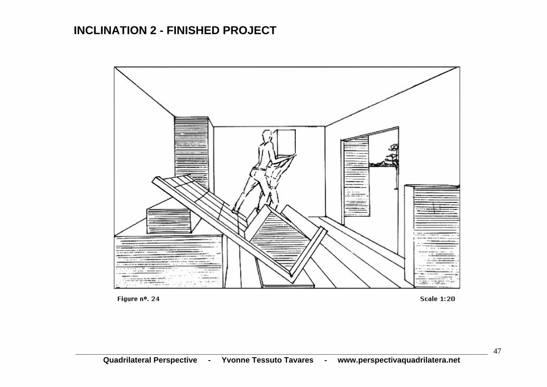
INCLINATION 2 - FINISHED PROJECT
_______________________________________________________________________________________________Quadrilateral Perspective - Yvonne Tessuto Tavares - www.perspectivaquadrilatera.net
47

HOW TO DRAW A SPIRAL STAIRCASE IN PARALLEL PERSPECTIVE
Draw the distance, support and horizon lines and the vanishing, view and depth points inside the visual field, as previously explained. Draw a squarecorresponding to the diameter of the staircase and divide it into angles of 45º. Find the bisectrix of these 45º angles as follows: Multiply the length of the angle by the expression 0.586. Figure nº 25 illustrates a square of 10x10cm (2 x 2 m in a scale of 1:20). In this case, the length of the angle is 5cm - multiply it by 0.586 0.586 x 5 = 2.930 round up to 3 cm
Mark 3 cm on the square base (width measurement line) starting at each vertex. See figure nº 25. From this point to the vanishing and depth points, find thelateral 3 cm and so forth. After finding the points on the square edges join these points with the lines that will pass by the perspective center of the square.
Now you have all the angles of the staircase steps already in perspective.
Figure nº 26 shows a circle drawn on the angles of the steps.
Figure nº 27 shows the raising of the steps within a box.
Figure nº 28 shows the spiral staircase already constructed.
_______________________________________________________________________________________________Quadrilateral Perspective - Yvonne Tessuto Tavares - www.perspectivaquadrilatera.net
48

HOW TO DRAW A SPIRAL STAIRCASE IN PARALLEL PERSPECTIVE (cont’d)
_______________________________________________________________________________________________
Quadrilateral Perspective - Yvonne Tessuto Tavares - www.perspectivaquadrilatera.net 49
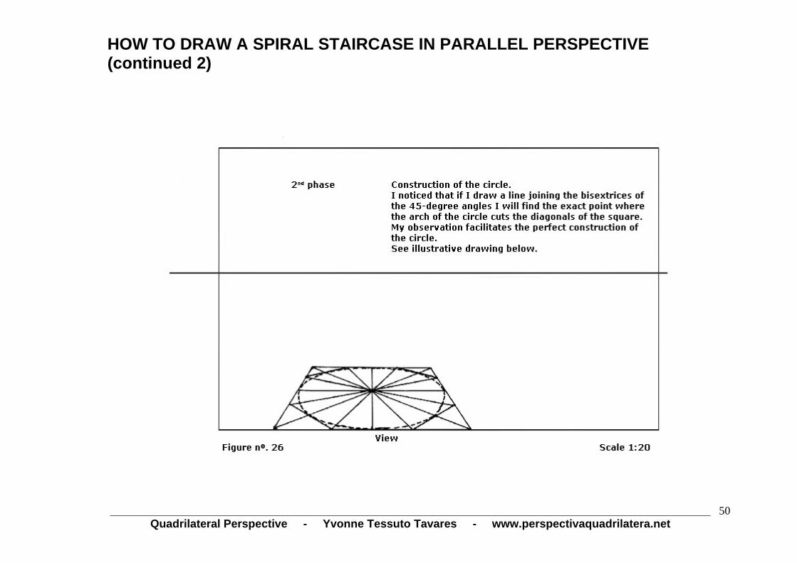
HOW TO DRAW A SPIRAL STAIRCASE IN PARALLEL PERSPECTIVE (continued 2)
_______________________________________________________________________________________________Quadrilateral Perspective - Yvonne Tessuto Tavares - www.perspectivaquadrilatera.net
50

HOW TO DRAW A SPIRAL STAIRCASE IN PARALLEL PERSPECTIVE (continued 3)
_______________________________________________________________________________________________Quadrilateral Perspective - Yvonne Tessuto Tavares - www.perspectivaquadrilatera.net
51
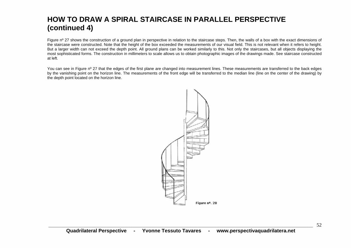
HOW TO DRAW A SPIRAL STAIRCASE IN PARALLEL PERSPECTIVE (continued 4) Figure nº 27 shows the construction of a ground plan in perspective in relation to the staircase steps. Then, the walls of a box with the exact dimensions of the staircase were constructed. Note that the height of the box exceeded the measurements of our visual field. This is not relevant when it refers to height. But a larger width can not exceed the depth point. All ground plans can be worked similarly to this. Not only the staircases, but all objects displaying the most sophisticated forms. The construction in millimeters to scale allows us to obtain photographic images of the drawings made. See staircase constructed at left.
You can see in Figure nº 27 that the edges of the first plane are changed into measurement lines. These measurements are transferred to the back edges by the vanishing point on the horizon line. The measurements of the front edge will be transferred to the median line (line on the center of the drawing) by the depth point located on the horizon line.
_______________________________________________________________________________________________Quadrilateral Perspective - Yvonne Tessuto Tavares - www.perspectivaquadrilatera.net
52
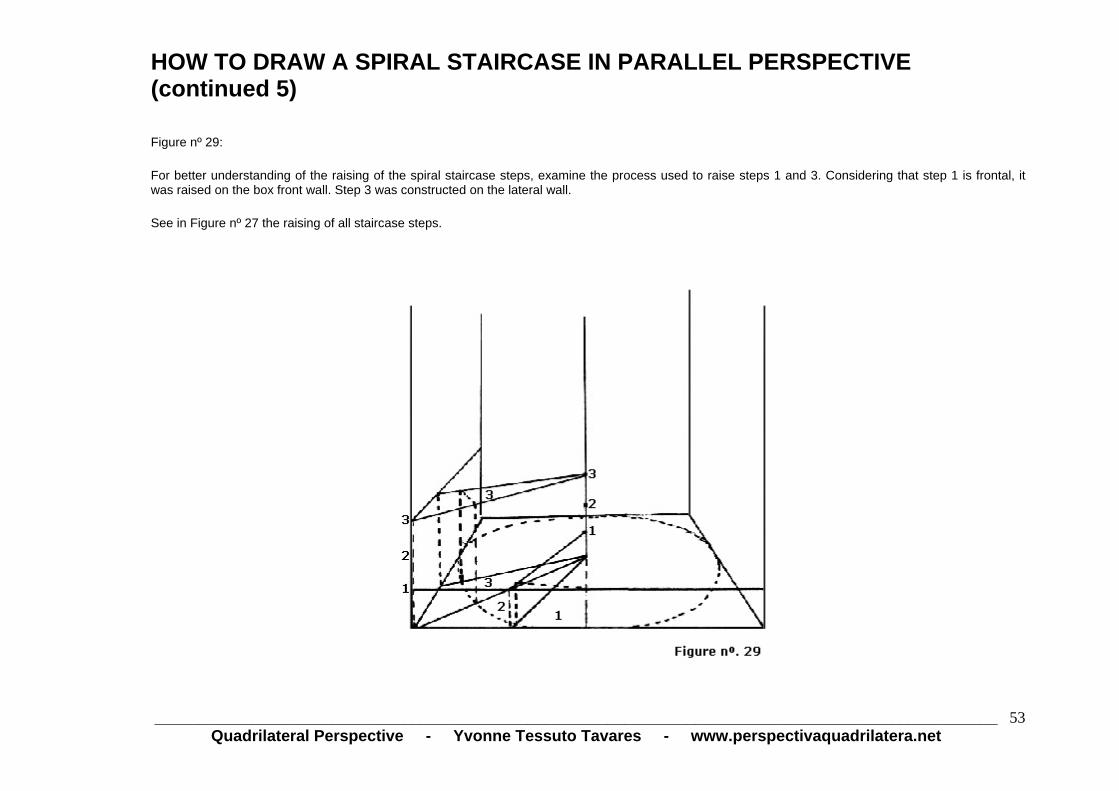
HOW TO DRAW A SPIRAL STAIRCASE IN PARALLEL PERSPECTIVE (continued 5) Figure nº 29:
For better understanding of the raising of the spiral staircase steps, examine the process used to raise steps 1 and 3. Considering that step 1 is frontal, it was raised on the box front wall. Step 3 was constructed on the lateral wall.
See in Figure nº 27 the raising of all staircase steps.
_______________________________________________________________________________________________Quadrilateral Perspective - Yvonne Tessuto Tavares - www.perspectivaquadrilatera.net
53

_______________________________________________________________________________________________Quadrilateral Perspective - Yvonne Tessuto Tavares - www.perspectivaquadrilatera.net
54
Figure nº 30 shows the construction of a door ajar. See how it was constructed: 1 — Calculate the door width on the width measurement line; transfer this width to the place of its construction by the vanishing point. 2 — The same measurement is found at the side of the door opening. 3 — Prolong line a, b, that goes from the door post up to the vanishing point and find point c. The distance between points c and e has the same
dimension of the door opening. 4 — Construct the angle of the door opening. 5 — Select any point of this angle. See point d. From there to point e, sketch a straight line. Prolong this straight line up to the horizon and locate the
vanishing point f. 6 — Sketch a line from point g to point f. Prolong this line until crossing with the vertical line referring to the door height.
7 — Calculate the door thickness and sketch a line parallel to the door vertical line.
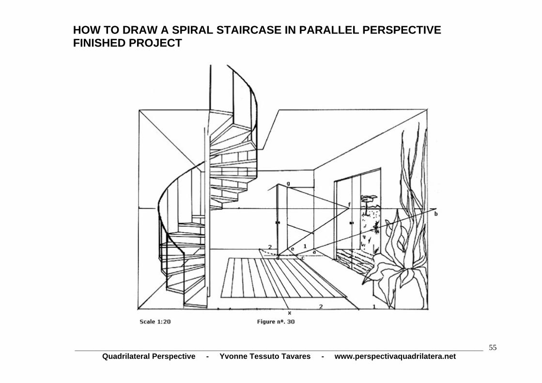
HOW TO DRAW A SPIRAL STAIRCASE IN PARALLEL PERSPECTIVE FINISHED PROJECT
_______________________________________________________________________________________________Quadrilateral Perspective - Yvonne Tessuto Tavares - www.perspectivaquadrilatera.net
55

_______________________________________________________________________________________________Quadrilateral Perspective - Yvonne Tessuto Tavares - www.perspectivaquadrilatera.net
56
AERIAL PARALLEL PERSPECTIVE
(2 VANISHING POINTS)
_______________________________________________________________________________________________Quadrilateral Perspective - Yvonne Tessuto Tavares - www.perspectivaquadrilatera.net
57
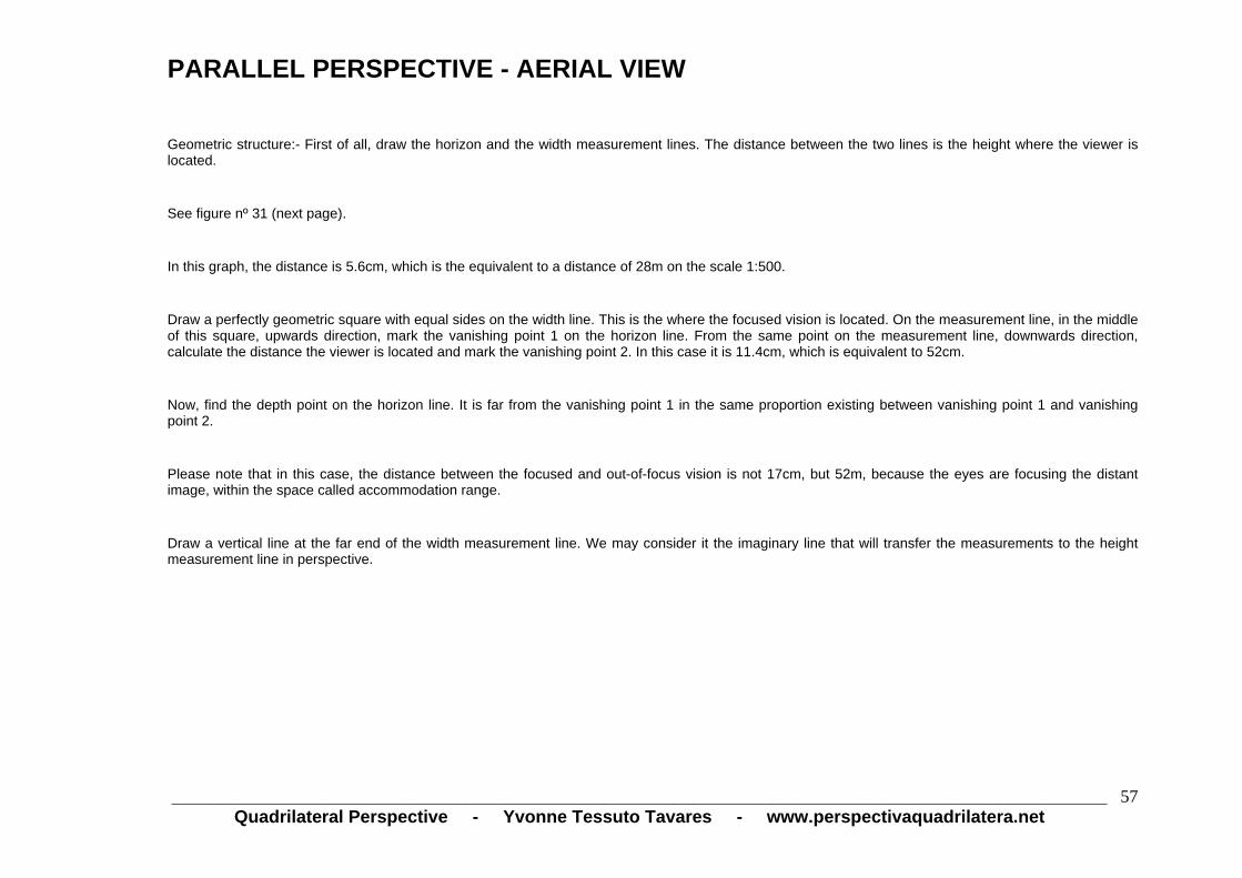
PARALLEL PERSPECTIVE - AERIAL VIEW
Geometric structure:- First of all, draw the horizon and the width measurement lines. The distance between the two lines is the height where the viewer is located.
See figure nº 31 (next page).
In this graph, the distance is 5.6cm, which is the equivalent to a distance of 28m on the scale 1:500.
Draw a perfectly geometric square with equal sides on the width line. This is the where the focused vision is located. On the measurement line, in the middle of this square, upwards direction, mark the vanishing point 1 on the horizon line. From the same point on the measurement line, downwards direction, calculate the distance the viewer is located and mark the vanishing point 2. In this case it is 11.4cm, which is equivalent to 52cm.
Now, find the depth point on the horizon line. It is far from the vanishing point 1 in the same proportion existing between vanishing point 1 and vanishing point 2.
Please note that in this case, the distance between the focused and out-of-focus vision is not 17cm, but 52m, because the eyes are focusing the distant image, within the space called accommodation range.
Draw a vertical line at the far end of the width measurement line. We may consider it the imaginary line that will transfer the measurements to the height measurement line in perspective.

PARALLEL PERSPECTIVE - AERIAL VIEW (GEOMETRIC STRUCTURE)
_______________________________________________________________________________________________
Quadrilateral Perspective - Yvonne Tessuto Tavares - www.perspectivaquadrilatera.net 58
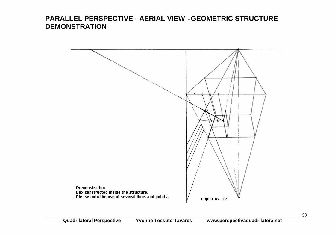
PARALLEL PERSPECTIVE - AERIAL VIEW - GEOMETRIC STRUCTURE DEMONSTRATION
_______________________________________________________________________________________________
Quadrilateral Perspective - Yvonne Tessuto Tavares - www.perspectivaquadrilatera.net 59

PARALLEL PERSPECTIVE - AERIAL VIEW
FINISHED PROJECT
_______________________________________________________________________________________________
Quadrilateral Perspective - Yvonne Tessuto Tavares - www.perspectivaquadrilatera.net 60

PARALLEL PERSPECTIVE - AERIAL VIEW
FINISHED PROJECT
_______________________________________________________________________________________________Quadrilateral Perspective - Yvonne Tessuto Tavares - www.perspectivaquadrilatera.net
61

_______________________________________________________________________________________________Quadrilateral Perspective - Yvonne Tessuto Tavares - www.perspectivaquadrilatera.net
62
PARALLEL PERSPECTIVE - AERIAL VIEW WITH A VIEW FROM BOTTOM TO TOP
In order to work with an aerial view from bottom to top, you have to invert the position of the previous structure
See Figure nº 35 (next page).
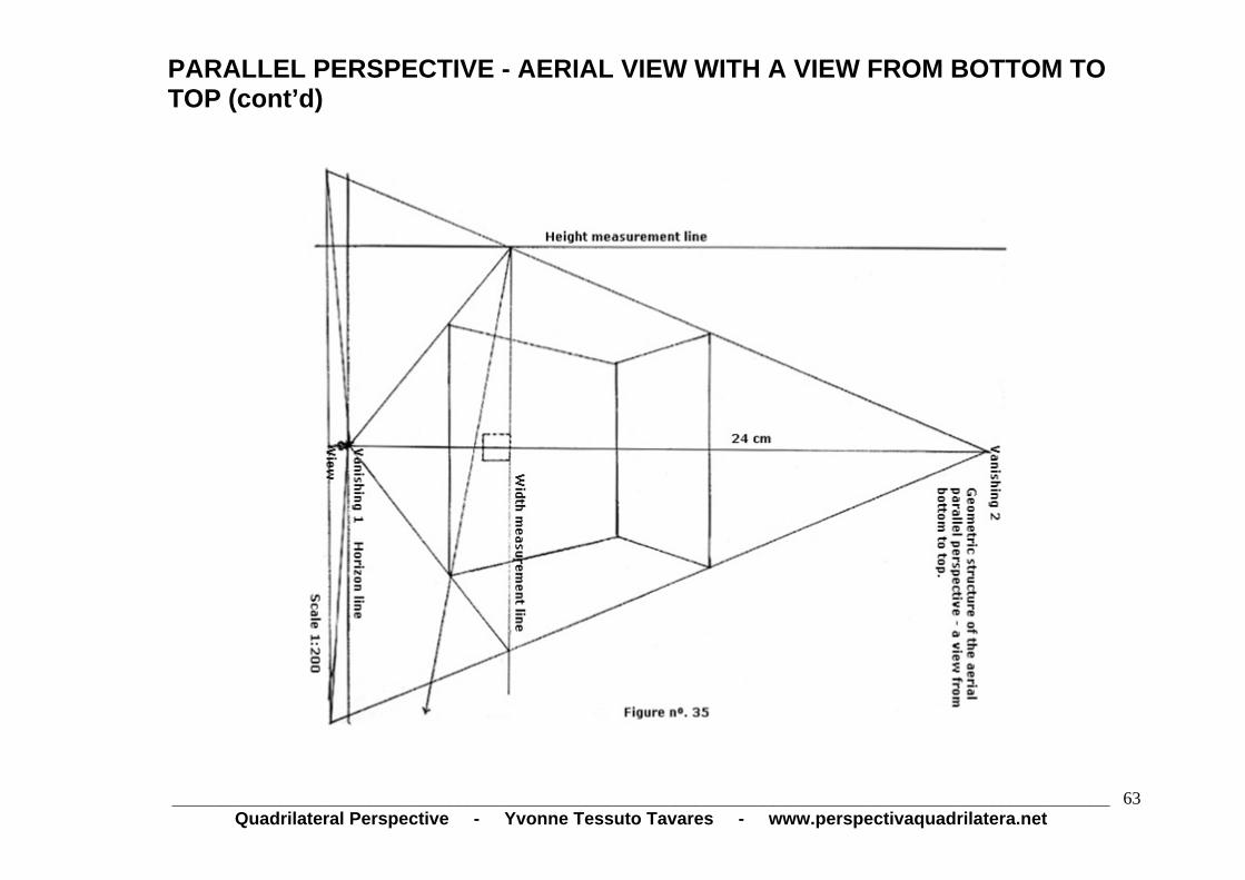
PARALLEL PERSPECTIVE - AERIAL VIEW WITH A VIEW FROM BOTTOM TO TOP (cont’d)
_______________________________________________________________________________________________
Quadrilateral Perspective - Yvonne Tessuto Tavares - www.perspectivaquadrilatera.net 63

PARALLEL PERSPECTIVE - AERIAL VIEW WITH A VIEW FROM BOTTOM TO TOP - FINISHED PROJECT
_______________________________________________________________________________________________Quadrilateral Perspective - Yvonne Tessuto Tavares - www.perspectivaquadrilatera.net
64

_______________________________________________________________________________________________Quadrilateral Perspective - Yvonne Tessuto Tavares - www.perspectivaquadrilatera.net
65
OBLIQUE PERSPECTIVE (2 VANISHING POINTS)
It is the perspective of objects in a sharp-corner position before our vision.
The oblique perspective can be constructed only inside a parallel perspective. The reasoning is as follows: the parallel perspective represents our visual field, a space with a limited lateral image of up to 3m to the right plus 3m to the left and an ample vision ahead, reaching the infinity on the horizon line.
This space, this visual field is fixed, without movement.
The oblique perspective represents the movement existing inside this static space.
Objects in oblique perspective are seen from a sharp corner and constructed with two opposed lateral points and their view point is the same both for the parallel and the oblique perspective, because the two perspectives represent the vision of a single viewer.

OBLIQUE PERSPECTIVE (2 VANISHING POINTS)) (cont’d)
_______________________________________________________________________________________________Quadrilateral Perspective - Yvonne Tessuto Tavares - www.perspectivaquadrilatera.net
66

_______________________________________________________________________________________________Quadrilateral Perspective - Yvonne Tessuto Tavares - www.perspectivaquadrilatera.net
67
CUBE IN OBLIQUE PERSPECTIVE
First of all, you have to construct the visual field, as explained in the parallel perspective.
Draw the support, horizon and distance lines and do not forget that you have to consider the measurement of 3 meters between the view point and the distance line.
Work to a scale.
Construct a square with a single vertex leaning on the support line.
Find the perspective center of the square.
Do not construct a square in the vertical position. Incline it slightly to the left or to the right.
Starting from the perspective center in a vertical line, find the view point 17cm away from the support line in the downwards direction. Mark the view point there.
From the view point, sketch lines parallel to those of the square up to the distance line and perpendicularly to the horizon line. Mark the vanishing point 1, the depth point and the vanishing point 2.
See in pages 70 and 71 (figures 38-B, 38-C, 38-D and 38-E) the several phases of the cube construction.

CONSTRUCTION OF A CUBE IN OBLIQUE PERSPECTIVE
Location of the vanishing, view and depth points on the horizon line.
The visual field is equal to that of the parallel perspective.
_______________________________________________________________________________________________Quadrilateral Perspective - Yvonne Tessuto Tavares - www.perspectivaquadrilatera.net
68

CONSTRUCTION OF A CUBE IN OBLIQUE PERSPECTIVE (cont’d)
_______________________________________________________________________________________________
Quadrilateral Perspective - Yvonne Tessuto Tavares - www.perspectivaquadrilatera.net 69

CONSTRUCTION OF A CUBE IN OBLIQUE PERSPECTIVE (continued 2)
_______________________________________________________________________________________________
Quadrilateral Perspective - Yvonne Tessuto Tavares - www.perspectivaquadrilatera.net 70

LOCATION OF THE MEASUREMENT POINTS With the two measurement points we are able to work the oblique perspective in millimeters, without drawing a plane in squares to find the desired width and depth.
See the figure below (figure nº 39). At the right of the plane the support line changed into the width measurement line and at the left in depth measurement line.
The measurement points MP1 and MP2 can only be located on the horizon line after the construction of the horizontal plane.
Mark the same dimension referring to the square on a shortening (scorcio) scale on the measurement lines.
With the line leaving from the measurement line to the vertex of the square, mark the measurement points MP1 and MP2 on the horizon line.
_______________________________________________________________________________________________Quadrilateral Perspective - Yvonne Tessuto Tavares - www.perspectivaquadrilatera.net
71

LOCATION OF THE MEASUREMENT POINTS (cont’d) To project a plane in vertical position, as shown in the graph at the right side, first of all we have to find the measurement points 1 and 2 on the horizon line.
In this case, the view point coincides with the depth line and there is no intersection between them as in the projection of the slightly inclined vertical plane.
See in graph that the distances of vanishing points 1 and 2 are identical.
To project the plane:- Mark the vanishing points 1 and 2 and the depth point on the horizon line.
Also on the horizon line, mark the measurement points 1 and 2, (square measures) 2cm away from the view point. Place one point at the right and the other at the left.
_______________________________________________________________________________________________
Quadrilateral Perspective - Yvonne Tessuto Tavares - www.perspectivaquadrilatera.net 72
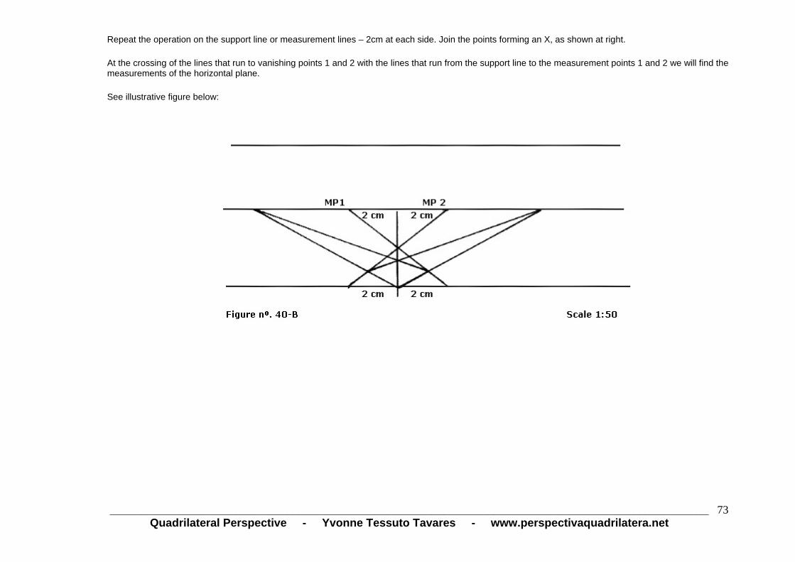
Repeat the operation on the support line or measurement lines – 2cm at each side. Join the points forming an X, as shown at right.
At the crossing of the lines that run to vanishing points 1 and 2 with the lines that run from the support line to the measurement points 1 and 2 we will find the measurements of the horizontal plane.
See illustrative figure below:
_______________________________________________________________________________________________Quadrilateral Perspective - Yvonne Tessuto Tavares - www.perspectivaquadrilatera.net
73

PLANE IN SQUARES IN OBLIQUE PERSPECTIVE The two lines that run to the depth point are essential for the construction of the plane in squares. The process is the same that is used in the 4th. phase of the cube construction.
_______________________________________________________________________________________________Quadrilateral Perspective - Yvonne Tessuto Tavares - www.perspectivaquadrilatera.net
74

_______________________________________________________________________________________________Quadrilateral Perspective - Yvonne Tessuto Tavares - www.perspectivaquadrilatera.net
75
OBLIQUE PERSPECTIVE
According to my theory, when we draw in oblique perspective we should have in mind that the box inside which we construct the objects in perspective is in sharp corner to our eyes and that this box is inside our visual field, represented by the parallel perspective.
Therefore, we can show figures in different perspectives in the same plane, that is, with one or two vanishing points in accordance with the positions of the figures.
See representative design, according to figure nº 42.

_______________________________________________________________________________________________Quadrilateral Perspective - Yvonne Tessuto Tavares - www.perspectivaquadrilatera.net
76
HOW TO DRAW THE OBLIQUE PERSPECTIVE AND THE PARALLEL PERSPECTIVE SIMULTANEOUSLY, INSIDE THE SAME VISUAL SPACE, WITH A SINGLE VIEW POINT
Construct the environment in parallel perspective, placing the distance, horizon and support lines to scale as previously explained.
Find the oblique perspective points: vanishing points 1 and 2, measurement points, depth point and mark also the vanishing and depth points of the parallel perspective.
See figure nº 42 where a plane in squares in oblique perspective is shown, developed inside a space in parallel perspective.
The line perpendicular to the horizon marks the vanishing point of the parallel perspective, the view point and the respective centers of the squares: of the vertical square and of the square on shortening scale (scorcio). Find this perpendicular line by drawing the vertical square and finding its perspective center by the diagonals that join their vertices.

HOW TO DRAW THE OBLIQUE PERSPECTIVE AND THE PARALLEL PERSPECTIVE SIMULTANEOUSLY, INSIDE THE SAME VISUAL SPACE, WITH A SINGLE VIEW POINT (cont’d) We find the parallel perspective and the oblique perspective points on the horizon line.
_______________________________________________________________________________________________Quadrilateral Perspective - Yvonne Tessuto Tavares - www.perspectivaquadrilatera.net
77
_______________________________________________________________________________________________Quadrilateral Perspective - Yvonne Tessuto Tavares - www.perspectivaquadrilatera.net
78
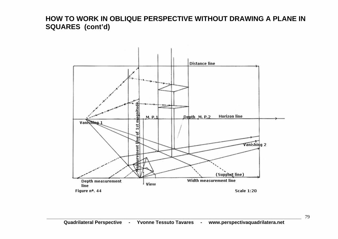
HOW TO WORK IN OBLIQUE PERSPECTIVE WITHOUT DRAWING A PLANE IN SQUARES
First of all, locate on the horizon line all vanishing and depth points and the measurement points 1 and 2.
Note that in oblique perspective, the edge of the first plane (measurement line of 1st magnitude) is the one that distributes the measurements. The same applies to the depth and width measurement lines.
The cube drawn in the space results from the square executed on the floor and from the measurement calculated on the measurement line of the 1st magnitude. The dotted line that runs to the vanishing points 1 and 2 transfers the measurements to the desired width and depth.
See figure nº 44 (next page).
HOW TO WORK IN OBLIQUE PERSPECTIVE WITHOUT DRAWING A PLANE IN SQUARES (cont’d)
_______________________________________________________________________________________________
Quadrilateral Perspective - Yvonne Tessuto Tavares - www.perspectivaquadrilatera.net 79

_______________________________________________________________________________________________Quadrilateral Perspective - Yvonne Tessuto Tavares - www.perspectivaquadrilatera.net
80
CONSTRUCTION OF A STAIRCASE INSIDE AN OBLIQUE PERSPECTIVE ENVIRONMENT 1 — Construct the environment as shown in figure nº 45. 2 — Locate the staircase and mark its width. 3 — Mark the depth of the 1st step.
4 — Mark the height of the 1st step on the edge of 1st magnitude, transferring it by the vanishing point 2 to the measurement line in perspective.
5 — Construct the 1st step. With two diagonal lines crossing the laterals of the step up to the vertical horizon line, mark the vanishing point of the
staircase inclination. 6 — Construct the staircase as shown in figure nº 45 (next page).

CONSTRUCTION OF A STAIRCASE INSIDE AN OBLIQUE PERSPECTIVE ENVIRONMENT (cont’d)
_______________________________________________________________________________________________Quadrilateral Perspective - Yvonne Tessuto Tavares - www.perspectivaquadrilatera.net
81

CONSTRUCTION OF A STAIRCASE INSIDE AN OBLIQUE PERSPECTIVE ENVIRONMENT - FINISHED PROJECT
_______________________________________________________________________________________________
Quadrilateral Perspective - Yvonne Tessuto Tavares - www.perspectivaquadrilatera.net 82

_______________________________________________________________________________________________Quadrilateral Perspective - Yvonne Tessuto Tavares - www.perspectivaquadrilatera.net
83
CONSTRUCTION OF A SPIRAL STAIRCASE
In the four phases for construction of a spiral staircase we can observe how to work the oblique perspective without constructing a plane in squares, which is replaced by the measurement points. They will give us the depth and width desired.
The staircase construction process is equal to that used in parallel perspective.

CONSTRUCTION OF A SPIRAL STAIRCASE (cont’d)
_______________________________________________________________________________________________Quadrilateral Perspective - Yvonne Tessuto Tavares - www.perspectivaquadrilatera.net
84

CONSTRUCTION OF A SPIRAL STAIRCASE (continued 2)
_______________________________________________________________________________________________Quadrilateral Perspective - Yvonne Tessuto Tavares - www.perspectivaquadrilatera.net
85

CONSTRUCTION OF A SPIRAL STAIRCASE (continued 3)
_______________________________________________________________________________________________
Quadrilateral Perspective - Yvonne Tessuto Tavares - www.perspectivaquadrilatera.net 86

CONSTRUCTION OF A SPIRAL STAIRCASE (continued 4)
_______________________________________________________________________________________________Quadrilateral Perspective - Yvonne Tessuto Tavares - www.perspectivaquadrilatera.net
87

CONSTRUCTION OF A SPIRAL STAIRCASE (continued 5)
_______________________________________________________________________________________________Quadrilateral Perspective - Yvonne Tessuto Tavares - www.perspectivaquadrilatera.net
88

CONSTRUCTION OF A SPIRAL STAIRCASE
FINISHED PROJECT
_______________________________________________________________________________________________Quadrilateral Perspective - Yvonne Tessuto Tavares - www.perspectivaquadrilatera.net
89

_______________________________________________________________________________________________Quadrilateral Perspective - Yvonne Tessuto Tavares - www.perspectivaquadrilatera.net
90
INCLINATION
After drawing the square on the support line, find the vanishing and depth points on the horizon line.
By the axis (vanishing point of the parallel perspective), make the inclination of the horizon line sketching the support line parallel to it. Transfer all vanishing and depth points to the fake horizon line.
From the vertex of the square drawn on the support line, sketch a line parallel to the view point line.
In any point of this line, sketch the sharp corner of the inclined cube, always paying attention to form an angle of 90º with the fake support line.

INCLINATION (cont’d)
_______________________________________________________________________________________________Quadrilateral Perspective - Yvonne Tessuto Tavares - www.perspectivaquadrilatera.net
91

_______________________________________________________________________________________________Quadrilateral Perspective - Yvonne Tessuto Tavares - www.perspectivaquadrilatera.net
92
CONSTRUCTION OF A BOX WITH RAISED LID, IN OBLIQUE PERSPECTIVE. The environment is in parallel perspective.
First of all, we construct the box in the desired dimensions. It is the same process used in former constructions in oblique perspective. We use the width, depth and height measurement lines, including the point on the horizon line.
To construct the inclined lid we sketch a vertical horizon line on the vanishing point 1. Then, we draw the box lid in vertical position. See figure 50, letter A. This vertical lid will have the same width and length dimension of the box already drawn. Construct the angle of the course of the lid from vertex a of the box lid to vertex b of the box. Mark the desired opening in this angle and by the vanishing point 2 sketch the line c. From point d in the lid opening angle, sketch a line up to point a, proceeding until reaching the vertical horizon line. Mark the vanishing point X there. From this vanishing point X up to vertex e of the vertical lid, proceeding up to crossing with line c, mark the point f there, referring to the width of the inclined lid. From point f to point g, that is the vertex of the box, sketch a line up to the vertical horizon line and mark the vanishing point Y. Calculate the height of the box lid on the depth measurement line. See figure nº 50 (next page).

CONSTRUCTION OF A BOX WITH RAISED LID, IN OBLIQUE PERSPECTIVE. The environment is in parallel perspective. (cont’d)
________________________Quadrilateral Perspective - Yvonne Tessuto Tavares - www.perspectivaquadrilatera.net
93 _______________________________________________________________________

CONSTRUCTION OF A BOX WITH RAISED LID, IN OBLIQUE PERSPECTIVE. The environment is in parallel perspective. (continued 2)
________________________Quadrilateral Perspective - Yvonne Tessuto Tavares - www.perspectivaquadrilatera.net
94 _______________________________________________________________________

_______________________________________________________________________________________________Quadrilateral Perspective - Yvonne Tessuto Tavares - www.perspectivaquadrilatera.net
95
AERIAL OBLIQUE PERSPECTIVE (3 VANISHING POINTS)
The process is identical to that of the aerial parallel perspective.
Sketch the horizon line and the measurement line. The distance between these two lines is the height at which the viewer is standing.
Locate the third point. From the center of the square remade in three dimensions, by the median line, calculate the distance the viewer is placed. This third point is called view point.
The vanishing points 1 and 2 and the depth point are found with lines parallel to the square leaned on the measurement line leaving from the view point. See lines A, B and C in the graph.
Two imaginary lines of measurement that do not run from the third point are necessary to find the height. One is located on the front near the edge and view point lines. The other is the lateral vertical line.
See points 1, 2, 3 and 4 in the graph, showing the transfers of measurement to the front edge in perspective.
The measurement calculated from point 1 is the measurement in perspective in point 4.
The out-of-focus vision is located in the view point and the vision focused in the square located on the measurement line. In this type of perspective the eyes focus the image in the so called accommodation range.
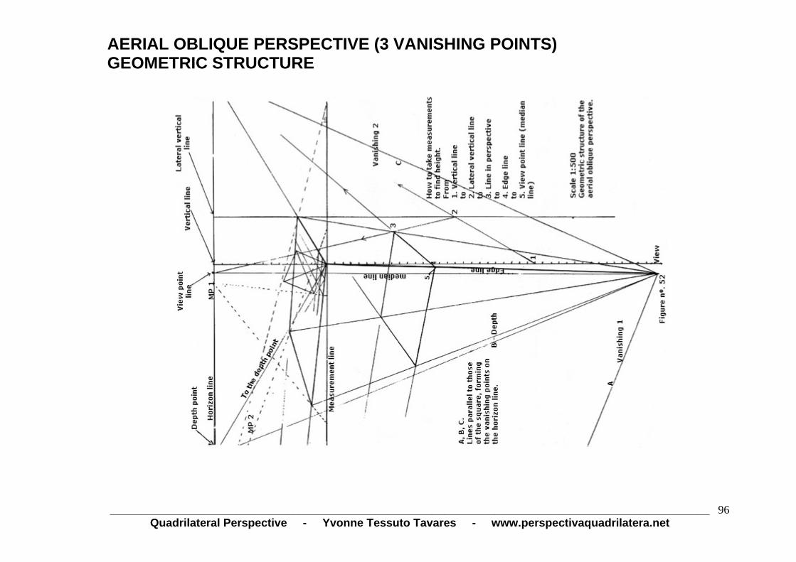
AERIAL OBLIQUE PERSPECTIVE (3 VANISHING POINTS) GEOMETRIC STRUCTURE
_______________________________________________________________________________________________Quadrilateral Perspective - Yvonne Tessuto Tavares - www.perspectivaquadrilatera.net
96

AERIAL OBLIQUE PERSPECTIVE (3 VANISHING POINTS)
FINISHED PROJECT
_______________________________________________________________________________________________Quadrilateral Perspective - Yvonne Tessuto Tavares - www.perspectivaquadrilatera.net
97

INTEGRATED PERSPECTIVE (5 VANISHING POINTS) The perspective is monocular.
Do the following test: bring the drawing in perspective 17cm close to your eyes; find the drawing vanishing point and close one of your eyes. The drawing will appear in third dimension, thus proving the efficacy of the constructive technique of the image.
_______________________________________________________________________________________________
Quadrilateral Perspective - Yvonne Tessuto Tavares - www.perspectivaquadrilatera.net 98

_______________________________________________________________________________________________Quadrilateral Perspective - Yvonne Tessuto Tavares - www.perspectivaquadrilatera.net
99
INTEGRATED PERSPECTIVE (5 VANISHING POINTS) (cont’d)
Integrated perspective is the association of all types of perspective resulting in a space totalization.
In the next pages we will find a demonstration of structure construction in several phases in order to provide a better understanding.
The crossing of lines of phase 1 show the points a and b. Point a corresponds to the vanishing point to where all the drawing lines converge. It is the infinity vanishing point on the horizon line. Points b are the distance points.
The space between points a and b corresponds to the distance in which the viewer is standing. The larger this space, smaller the structure distortion will be.

INTEGRATED PERSPECTIVE (5 VANISHING POINTS) (continued 2)
Please go to the next page to see how to calculate the depth.
_______________________________________________________________________________________________
Quadrilateral Perspective - Yvonne Tessuto Tavares - www.perspectivaquadrilatera.net 100
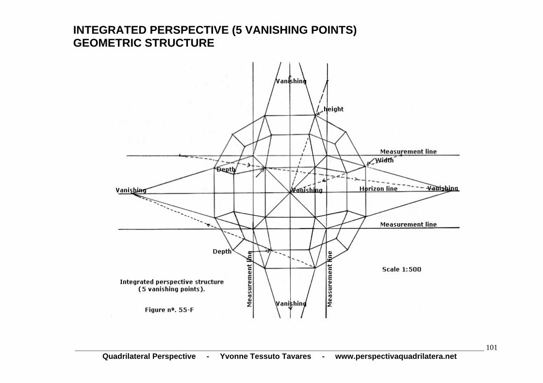
INTEGRATED PERSPECTIVE (5 VANISHING POINTS) GEOMETRIC STRUCTURE
_______________________________________________________________________________________________Quadrilateral Perspective - Yvonne Tessuto Tavares - www.perspectivaquadrilatera.net
101
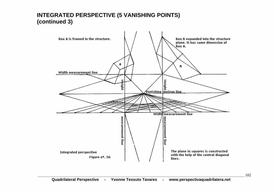
INTEGRATED PERSPECTIVE (5 VANISHING POINTS) (continued 3)
_______________________________________________________________________________________________
Quadrilateral Perspective - Yvonne Tessuto Tavares - www.perspectivaquadrilatera.net 102

INTEGRATED PERSPECTIVE (5 VANISHING POINTS) FINISHED PROJECT
_______________________________________________________________________________________________
Quadrilateral Perspective - Yvonne Tessuto Tavares - www.perspectivaquadrilatera.net 103
_______________________________________________________________________________________________Quadrilateral Perspective - Yvonne Tessuto Tavares - www.perspectivaquadrilatera.net
104
STUDY ON THE SYSTEM
Now, I will conduct a brief study on the
system for better understanding of the
new basic concept of exact perspective.

_______________________________________________________________________________________________Quadrilateral Perspective - Yvonne Tessuto Tavares - www.perspectivaquadrilatera.net
105
HEIGHT OF THE HORIZON LINE
We normally use the horizon line height at 1.70m, because this is the average height of a man.
If we want to dislocate this line upwards or downwards we have to adopt the same system used for the horizon line at 1.70m.
We have to calculate a distance of 3m between the view point and the distance line. That is the same distance that we should have between the vanishing point and the depth point on the horizon line.
In order to provide a better understanding, in the following pages I make a brief study dislocating the horizon line 50cm upwards and 50cm downward.
HOW TO DISLOCATE THE HORIZON LINE
For better understanding of this process we have to carry out an examination of the agreement existing among the parts of the system, in order to check the harmony that involves this overlapping of images.
By means of sketched arches, as shown in the graphs in the following pages, we will be able to see a pentagonal harmony that involves the whole system.
Leonardo da Vinci depicted the pentagon as the symbol of life. Its symmetry is easily found in nature, botany and zoology.
I believe that the new basic concept resulting from this overlapping of images can be considered scientific in view of the satisfactory results of the practical experiment. The drawings present genuine images.
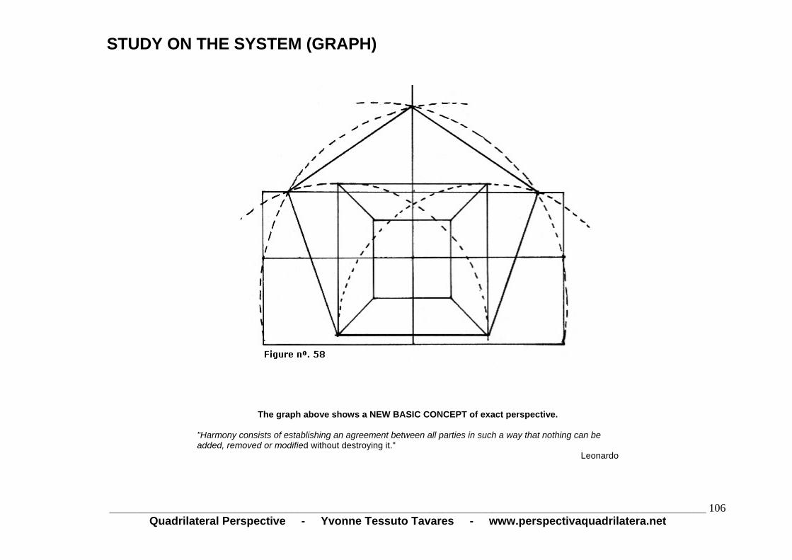
STUDY ON THE SYSTEM (GRAPH)
The graph above shows a NEW BASIC CONCEPT of exact perspective.
"Harmony consists of establishing an agreement between all parties in such a way that nothing can be added, removed or modified without destroying it."
Leonardo
_______________________________________________________________________________________________Quadrilateral Perspective - Yvonne Tessuto Tavares - www.perspectivaquadrilatera.net
106

FOCUSED VISION
_______________________________________________________________________________________________Quadrilateral Perspective - Yvonne Tessuto Tavares - www.perspectivaquadrilatera.net
107
Our vision crosses forming an x. The left eye goes to the right and forms arch E.
The right eye goes to the left and forms the arch D.
And so we have an angle of 60º that provides a focused and sharp vision. Everything we see out of this angle will have a distorted image.
OUT-OF-FOCUS VISION
It is interesting to note that the joining of these two arches of 90º each forms the angle of 60º of the vision focused 17cm farther.

NEW REASONING FOR THE PERSPECTIVE
Out-of-focus vision on the focused vision.
There is a distance of 17cm between the two images.
There is regular pentagon with its five equal sides on this system.
See later how to construct it with a compass, without using the medium and extreme ratio and without constructing a circle.
_______________________________________________________________________________________________
Quadrilateral Perspective - Yvonne Tessuto Tavares - www.perspectivaquadrilatera.net 108

NEW REASONING FOR THE PERSPECTIVE (cont’d) We thrust the compass needle into a and sketch an arch leaving from the point A.
And so, successively, from the lower-case letters we will sketch arches leaving from the capital letters.
These arches are the basic structure for the construction of the pentagon on the linear perspective system.
According to my theory, our visual field is framed in this pentagon.
We will always draw in the space between the pentagon base (support line) up to the horizontal line that joins the two vertices of the pentagon (distance line).
See explanatory figures below:
_______________________________________________________________________________________________Quadrilateral Perspective - Yvonne Tessuto Tavares - www.perspectivaquadrilatera.net
109

HORIZON LINE 1.70m HIGH So we have a pentagon on the central linear perspective.
Although it is not a pentagon inscribed in a circle (the figure is rather wide) it is a pentagonal figure with its five equal sides.
The distance existing among points a, b and c, d will always be of three meters. Even when the horizon line is dislocated.
_______________________________________________________________________________________________Quadrilateral Perspective - Yvonne Tessuto Tavares - www.perspectivaquadrilatera.net
110

HORIZON LINE AT 1.20m FROM THE FLOOR Horizon line at 1.20m from the floor. The viewer is 50cm lower than the floor or seated on the floor.
WE WILL NO LONGER HAVE A PERFECT PENTAGON.
However, we can work in perspective in the respective space, that is, between the support and distance lines. The pentagon has not been distorted in this space.
_______________________________________________________________________________________________Quadrilateral Perspective - Yvonne Tessuto Tavares - www.perspectivaquadrilatera.net
111

HORIZON LINE 2.20m HIGH Horizon line 2.20m high. The viewer is at 0.5m from the floor.
WE WILL NO LONGER HAVE A PERFECT PENTAGON.
Nevertheless, we can normally work in perspective in the space between the distance line and support lines. The measurements were not altered there. The three sides of the pentagon correspond to the cube measurements.
_______________________________________________________________________________________________
Quadrilateral Perspective - Yvonne Tessuto Tavares - www.perspectivaquadrilatera.net 112

STUDY CONCLUSION HORIZON LINE 1.70m HIGH The DISTANCE LINE...............is the horizontal height that joins the vertices of the pentagon.
The SUPPORT LINE................is the base of the pentagon.
The HORIZON LINE.................represents the viewer’s eye level.
The VANISHING POINT...........is the remotest point, the farthest viewer’s point. It is located on the infinity, on the horizon.
The VIEW POINT.....................is the place where the viewer is, 17cm away from the focused vision.
The DEPTH POINTS...............are the lateral extremities of our out-of-focus vision transferred to the horizon line.
Our vision obtains a clear image 17cm ahead of our eyes, comprising a space of a 3x3 m square on the vertical plane. It is the 60º vision.
Our out-of-focus vision, located prior to reaching 17cm is made up of two squares measuring 3x3 m. This gives us a vision of 180º.
_______________________________________________________________________________________________Quadrilateral Perspective - Yvonne Tessuto Tavares - www.perspectivaquadrilatera.net
113

_______________________________________________________________________________________________Quadrilateral Perspective - Yvonne Tessuto Tavares - www.perspectivaquadrilatera.net
114
PENTAGONAL SYMMETRY IN PAINTING - COSMIC HARMONY
The analyses of paintings by Renaissance artists revealed that the composition of their works is based on a rotational pentagonal symmetry very similar to that found in our solar system.
In the Renaissance period, it was widely believed that the Earth was flat and the center of the Universe. No one was allowed to contradict the new scientific discoveries without running the risk of capital punishment for the audacity.
Leonardo had one of the best scientific minds of his time, he was very creative and fond of studying; he tried to depict his cosmic discoveries in his paintings. Not only him, but his contemporaries as well: Raffaelo, Michelangelo and others. These artists did not make their works inside the geometric frame of the central linear perspective, but rather on it, in order to eliminate the hardness and the static resulting from purely geometric lines.
The pictorial space divided into three successive planes was worked as follows: the 2nd and 3rd planes performed by central linear perspective. The 1st one by a two-dimension-cyclical symmetry coupled to the central linear perspective. This is the origin of the third dimension found in Leonardo’s works.
This geometric frame performed mainly in Leonardo’s work called “The Last Supper” was the origin of the baroque. We note in it the static of the background constructed by the linear perspective and the dynamism of the figures and their robes represented in first plane by rotational symmetry.
In his book “Leonardo” (Gráf.Univ.M. Gerais – BH 1995), Santiago Americano Freire discloses his discovery: the invisible structure existing in the great master’s works. He called it stereo perspective and defined it as follows: “Stereo-perspective (new for us) results from a cyclical symmetry of non-finite groups of possible rotations at two dimensions, coupled with the central linear perspective”.
It is interesting to note that the overlapping of images that makes up the new basic concept of my new linear perspective has a pentagon “coupled” to it. It is not a pentagon inscribed in a circle as in Santiago’s stereo perspective, but it is a pentagonal figure with five equal sides. The entire geometric frame of this new exact perspective is performed between the two lines generated by this imaginary pentagon: the line of its base and the line that joins its two opposed lateral vertices.
The stereo perspective will not be covered in this book because it is the work by another author. However, I would like to mention that the harmony and rhythm that it confers to the composition, either figurative or non-figurative and to the third dimension, when it is coupled to the linear perspective, is something that the painter can not ignore.

_______________________________________________________________________________________________Quadrilateral Perspective - Yvonne Tessuto Tavares - www.perspectivaquadrilatera.net
115
CONCLUSION
This book aims to overcome the difficulties presented by exact perspective in three-dimensional drawings, by introducing a new reasoning to remake the vertical plane in three dimensions, where the visual cone is no longer the fundamental idea.
The work on exact perspective introduced herein is the result of many years of study and research conducted in the perspective field, in order to free the three-dimensional space on the drawing.
I hope that the University that has several functions, including that of catalyzing ideas, opinions and hypotheses will study and examine the new basic concept of this new exact perspective measured in millimeters. It is the only one that has geometric structures for each type of perspective, whose drawings present reliable images.
The new structures of the Quadrilateral Perspective under vectorial form becomes a powerful algorithm for solving the three-dimensional vision problem, which applied to the construction of a software will allow obtaining movement with a small amount of processing. Example: applied to animated cartoon software in a simple computer.