qsig(voice networking) 1. overview 2. overall networking configuration 3. lg ip networking solution...
TRANSCRIPT
QSIG(Voice Networking)
1. Overview1. Overview2. Overall Networking Configuration2. Overall Networking Configuration3. LG IP Networking Solution3. LG IP Networking Solution4. Feature4. Feature5. PRI QSIG Connection5. PRI QSIG Connection6. VoIP QSIG Connection6. VoIP QSIG Connection7. Feature Operation7. Feature Operation
1. Overview
LDK Voice networking provides a way of communication to inter-work
with networked system over Internet(VoIP) or ISDN.
LDK provides uniform numbering plan for all users in the network
The networked systems can be considered as one system.
Extension in any system can talk with other system like extension call
Up to 72 systems can be inter-working via public or private network
LDK supports the total solution from Home office to Headquarter office
with LG Systems (IP LDK-100/300/300E, IP LDK-20, NEXER and IPECS)
1/19

2. Overall Networking Configuration
ISDN PRI & IP Network
2/19
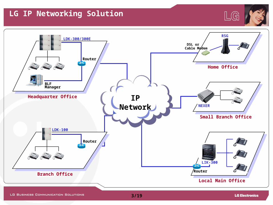
3. LG IP Networking Solution
NEXER
Small Branch Office
IP Network
Router
LDK-300/300E
BLF Manager
Headquarter Office
Router
LDK-100
Branch Office
DSL or Cable Modem
Home Office
RSG
Router
LIK-300
Local Main Office
3/19
4. Feature
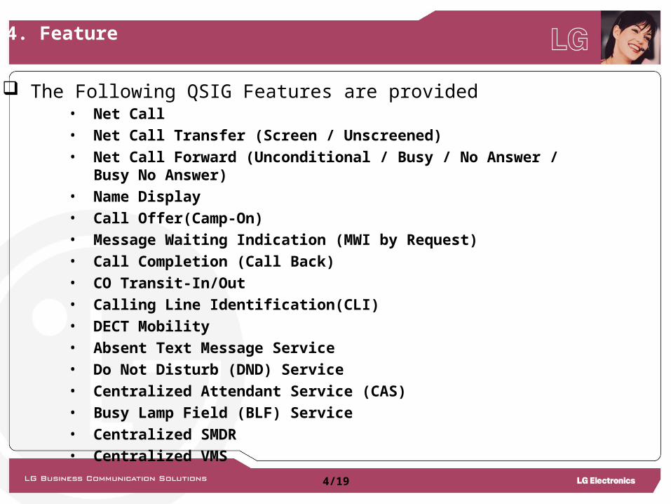
• Net Call• Net Call Transfer (Screen / Unscreened)• Net Call Forward (Unconditional / Busy / No Answer / Busy No Answer)• Name Display• Call Offer(Camp-On)• Message Waiting Indication (MWI by Request)• Call Completion (Call Back)• CO Transit-In/Out• Calling Line Identification(CLI)• DECT Mobility• Absent Text Message Service• Do Not Disturb (DND) Service• Centralized Attendant Service (CAS)• Busy Lamp Field (BLF) Service• Centralized SMDR• Centralized VMS
The Following QSIG Features are provided
4/19
5. PRI QSIG Connection
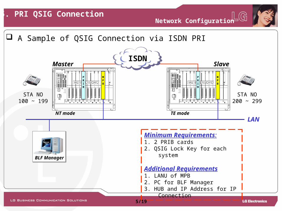
Minimum Requirements:1. 2 PRIB cards2. QSIG Lock Key for each system
Additional Requirements1. LANU of MPB2. PC for BLF Manager3. HUB and IP Address for IP Connection
A Sample of QSIG Connection via ISDN PRI
Master Slave
LANTE modeNT mode
BLF Manager
STA NO100 ~ 199
STA NO200 ~ 299
PRIB
PRIB
MPB
MPB
ISDN
Network Configuration
5/19
5. PRI QSIG Connection
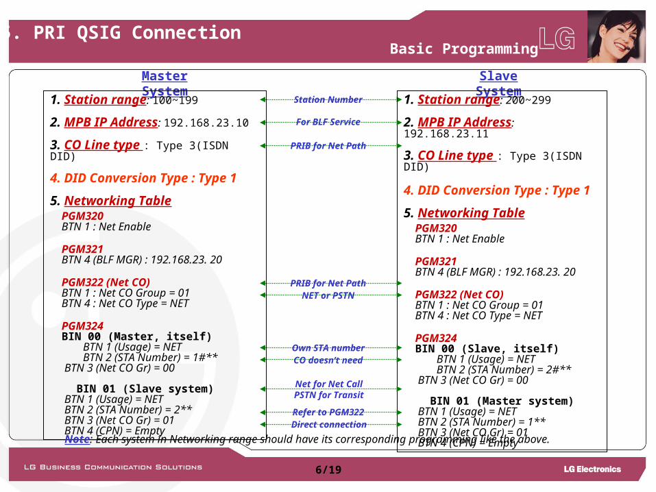
Master System
1. Station range: 100~199
2. MPB IP Address: 192.168.23.10
3. CO Line type : Type 3(ISDN DID)
4. DID Conversion Type : Type 1 5. Networking Table PGM320 BTN 1 : Net Enable
PGM321 BTN 4 (BLF MGR) : 192.168.23. 20
PGM322 (Net CO) BTN 1 : Net CO Group = 01 BTN 4 : Net CO Type = NET
PGM324 BIN 00 (Master, itself) BTN 1 (Usage) = NET BTN 2 (STA Number) = 1#** BTN 3 (Net CO Gr) = 00
BIN 01 (Slave system) BTN 1 (Usage) = NET BTN 2 (STA Number) = 2** BTN 3 (Net CO Gr) = 01 BTN 4 (CPN) = Empty
Note: Each system in Networking range should have its corresponding programming like the above.
Slave System
1. Station range: 200~299
2. MPB IP Address: 192.168.23.11
3. CO Line type : Type 3(ISDN DID)
4. DID Conversion Type : Type 1 5. Networking Table PGM320 BTN 1 : Net Enable
PGM321 BTN 4 (BLF MGR) : 192.168.23. 20
PGM322 (Net CO) BTN 1 : Net CO Group = 01 BTN 4 : Net CO Type = NET
PGM324 BIN 00 (Slave, itself) BTN 1 (Usage) = NET BTN 2 (STA Number) = 2#** BTN 3 (Net CO Gr) = 00
BIN 01 (Master system) BTN 1 (Usage) = NET BTN 2 (STA Number) = 1** BTN 3 (Net CO Gr) = 01 BTN 4 (CPN) = Empty
Basic Programming
Station Number
For BLF Service
PRIB for Net Path
PRIB for Net PathNET or PSTN
Direct connectionRefer to PGM322
Own STA numberCO doesn’t need
Net for Net CallPSTN for Transit
6/19
6. VoIP QSIG Connection
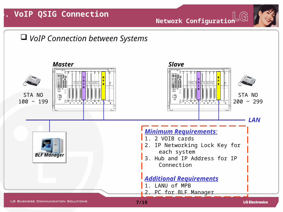
Minimum Requirements:1. 2 VOIB cards2. IP Networking Lock Key for each system3. Hub and IP Address for IP Connection
Additional Requirements1. LANU of MPB2. PC for BLF Manager
VoIP Connection between Systems
Master Slave
LAN
BLF Manager
STA NO100 ~ 199
STA NO200 ~ 299
MPB
MPB
VOIB
VOIB
Network Configuration
7/19
6. VoIP QSIG Connection
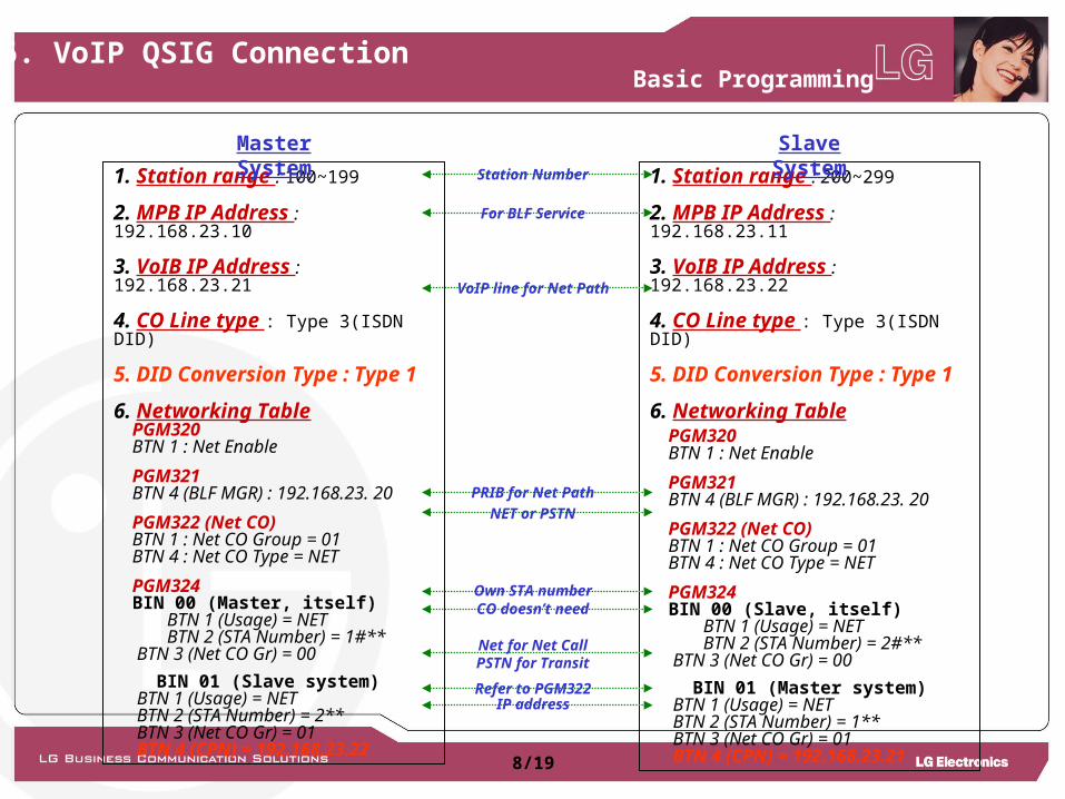
1. Station range : 100~199
2. MPB IP Address : 192.168.23.10
3. VoIB IP Address : 192.168.23.21
4. CO Line type : Type 3(ISDN DID)
5. DID Conversion Type : Type 1 6. Networking Table PGM320 BTN 1 : Net Enable
PGM321 BTN 4 (BLF MGR) : 192.168.23. 20
PGM322 (Net CO) BTN 1 : Net CO Group = 01 BTN 4 : Net CO Type = NET
PGM324 BIN 00 (Master, itself) BTN 1 (Usage) = NET BTN 2 (STA Number) = 1#** BTN 3 (Net CO Gr) = 00
BIN 01 (Slave system) BTN 1 (Usage) = NET BTN 2 (STA Number) = 2** BTN 3 (Net CO Gr) = 01 BTN 4 (CPN) = 192.168.23.22
1. Station range : 200~299
2. MPB IP Address : 192.168.23.11
3. VoIB IP Address : 192.168.23.22
4. CO Line type : Type 3(ISDN DID)
5. DID Conversion Type : Type 1 6. Networking Table PGM320 BTN 1 : Net Enable
PGM321 BTN 4 (BLF MGR) : 192.168.23. 20
PGM322 (Net CO) BTN 1 : Net CO Group = 01 BTN 4 : Net CO Type = NET
PGM324 BIN 00 (Slave, itself) BTN 1 (Usage) = NET BTN 2 (STA Number) = 2#** BTN 3 (Net CO Gr) = 00
BIN 01 (Master system) BTN 1 (Usage) = NET BTN 2 (STA Number) = 1** BTN 3 (Net CO Gr) = 01 BTN 4 (CPN) = 192.168.23.21
Basic Programming
Master System
Slave SystemStation Number
For BLF Service
VoIP line for Net Path
PRIB for Net Path
NET or PSTN
IP addressRefer to PGM322
Own STA numberCO doesn’t need
Net for Net CallPSTN for Transit
8/19
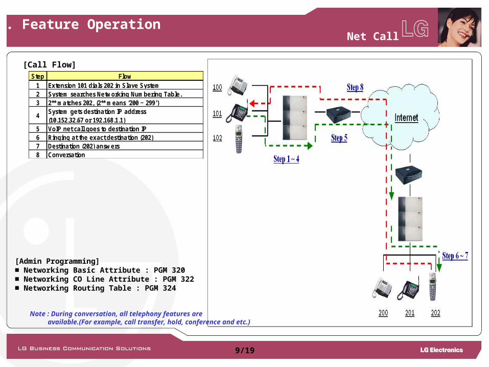
[Admin Programming]■ Networking Basic Attribute : PGM 320■ Networking CO Line Attribute : PGM 322■ Networking Routing Table : PGM 324
[Call Flow]
Note : During conversation, all telephony features are available.(For example, call transfer, hold, conference and etc.)
Net Call
Step Flow1 Extension 101 dials 202 in Slave System2 System searches Networking Numbering Table.3 2** matches 202, (2** means ‘200 ~ 299’)
4System gets destination IP address(10.152.32.67 or 192.168.1.1)
5 VoIP net call goes to destination IP6 Ringing at the exact destination (202)7 Destination (202) answers8 Conversation
7. Feature Operation
9/19
Internet
PSTN or ISDN
Step 3
202
100
Step 1 ~ 2
Step 4
Step 5
Step 6
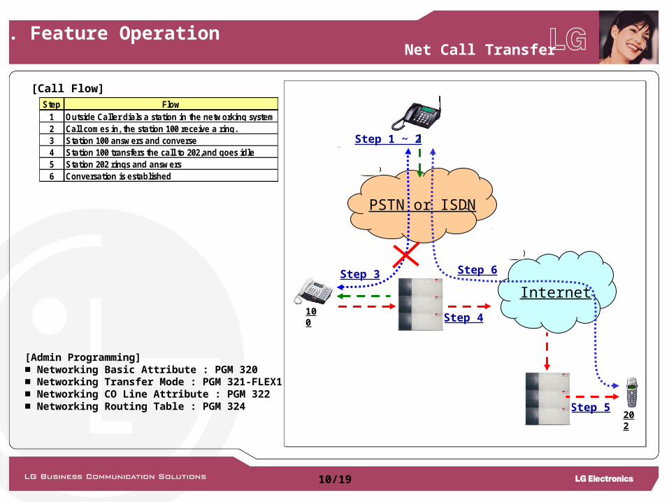
[Admin Programming]■ Networking Basic Attribute : PGM 320■ Networking Transfer Mode : PGM 321-FLEX1■ Networking CO Line Attribute : PGM 322■ Networking Routing Table : PGM 324
Net Call Transfer
Step Flow1 Outside Caller dials a station in the networking system2 Call comes in, the station 100 receive a ring.3 Station 100 answers and converse4 Station 100 transfers the call to 202,and goes idle5 Station 202 rings and answers6 Conversation is established
[Call Flow]
7. Feature Operation
10/19

Internet
PSTN or ISDN
Step 1
202
100
Step 2
Step 3
Step 4
Step 5
[Admin Programming]■ Call Forward Attribute : PGM 111-FLEX2■ Networking Basic Attribute : PGM 320■ Networking Transfer Mode : PGM 321-FLEX1■ Networking CO Line Attribute : PGM 322■ Networking Routing Table : PGM 324
Net Call Forward
Step Flow1 Station 100 set forward to 2022 Outside Caller calls Station 1003 Call is forwarding to Station 2024 Station 202 rings instead of 100.5 Conversation
[Call Flow]
7. Feature Operation
11/19
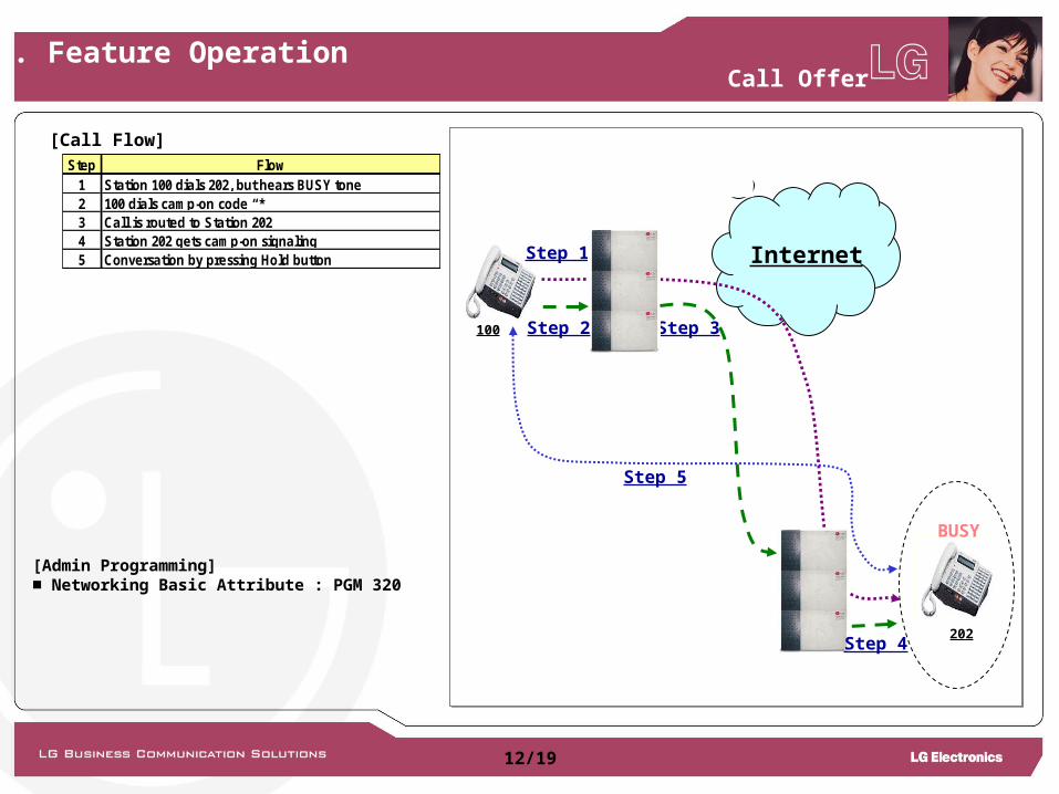
[Admin Programming]■ Networking Basic Attribute : PGM 320
InternetStep 1
202
100 Step 3
BUSY
Step 2
Step 4
Step 5
Call Offer
[Call Flow]Step Flow
1 Station 100 dials 202, but hears BUSY tone2 100 dials camp-on code “*”3 Call is routed to Station 2024 Station 202 gets camp-on signaling5 Conversation by pressing Hold button
7. Feature Operation
12/19
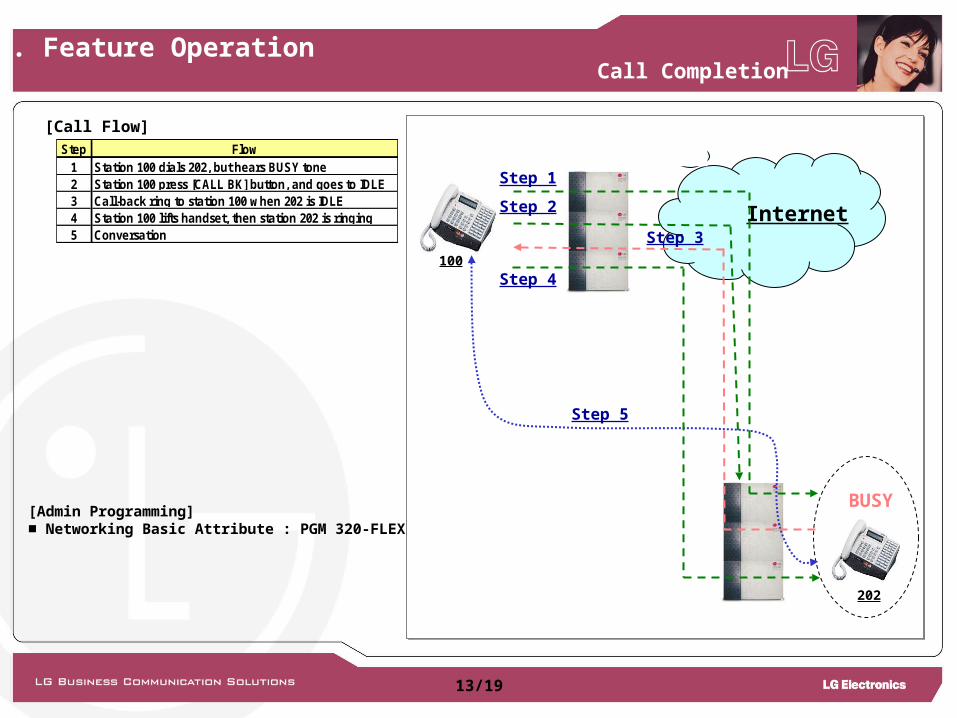
[Admin Programming]■ Networking Basic Attribute : PGM 320-FLEX8
Internet
Step 1
202
100
Step 3
BUSY
Step 2
Step 4
Step 5
Call Completion
[Call Flow]Step Flow
1 Station 100 dials 202, but hears BUSY tone2 Station 100 press [CALL BK] button, and goes to IDLE3 Call-back ring to station 100 when 202 is IDLE4 Station 100 lifts handset, then station 202 is ringing5 Conversation
7. Feature Operation
13/19

[Admin Programming]■ Networking Routing Table : PGM 324
Internet
PSTN or ISDN
202
Step 1
Step 3
Step 4
Step 5
Step 2
Additional Programming Master :Master : PGM 143 FLEX 4 (DID Conversion Type) = 2PGM 231 (Flexible DID Table) = Assign Slave extension
Additional Programming Master :Master : PGM 143 FLEX 4 (DID Conversion Type) = 2PGM 231 (Flexible DID Table) = Assign Slave extension
CO Transit-In
[Call Flow]Step Flow
1 Outside Caller dials a station in slave system
2Call comes in master system and search networkingnumbering plan table.
3Master transfers the call request to the foundnetworking system.
4 Call is ringing to station 2025 Conversation
7. Feature Operation
14/19
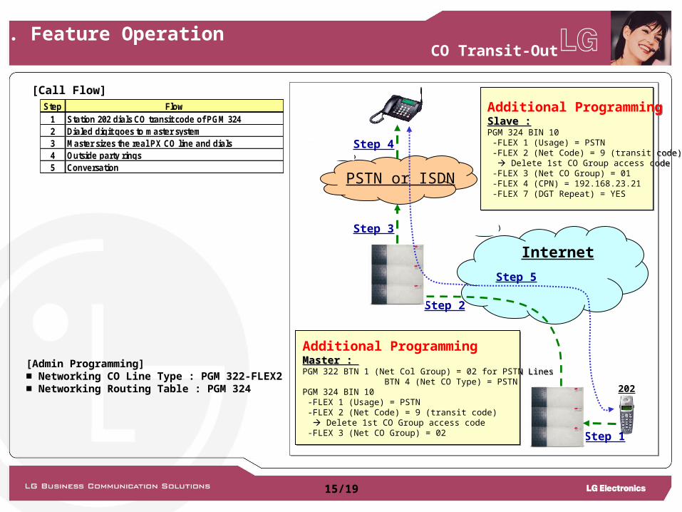
[Admin Programming]■ Networking CO Line Type : PGM 322-FLEX2■ Networking Routing Table : PGM 324
Internet
PSTN or ISDN
202
Step 4
Step 2
Step 1
Step 5
Step 3
Additional Programming Master : Master : PGM 322 BTN 1 (Net Col Group) = 02 for PSTN Lines BTN 4 (Net CO Type) = PSTNPGM 324 BIN 10 -FLEX 1 (Usage) = PSTN -FLEX 2 (Net Code) = 9 (transit code) Delete 1st CO Group access code -FLEX 3 (Net CO Group) = 02
Additional Programming Master : Master : PGM 322 BTN 1 (Net Col Group) = 02 for PSTN Lines BTN 4 (Net CO Type) = PSTNPGM 324 BIN 10 -FLEX 1 (Usage) = PSTN -FLEX 2 (Net Code) = 9 (transit code) Delete 1st CO Group access code -FLEX 3 (Net CO Group) = 02
Additional Programming Slave :Slave :PGM 324 BIN 10 -FLEX 1 (Usage) = PSTN -FLEX 2 (Net Code) = 9 (transit code) Delete 1st CO Group access code -FLEX 3 (Net CO Group) = 01 -FLEX 4 (CPN) = 192.168.23.21 -FLEX 7 (DGT Repeat) = YES
Additional Programming Slave :Slave :PGM 324 BIN 10 -FLEX 1 (Usage) = PSTN -FLEX 2 (Net Code) = 9 (transit code) Delete 1st CO Group access code -FLEX 3 (Net CO Group) = 01 -FLEX 4 (CPN) = 192.168.23.21 -FLEX 7 (DGT Repeat) = YES
CO Transit-Out
[Call Flow]Step Flow
1 Station 202 dials CO transit code of PGM 3242 Dialed digit goes to master system3 Master sizes the real PX CO line and dials4 Outside party rings5 Conversation
7. Feature Operation
15/19
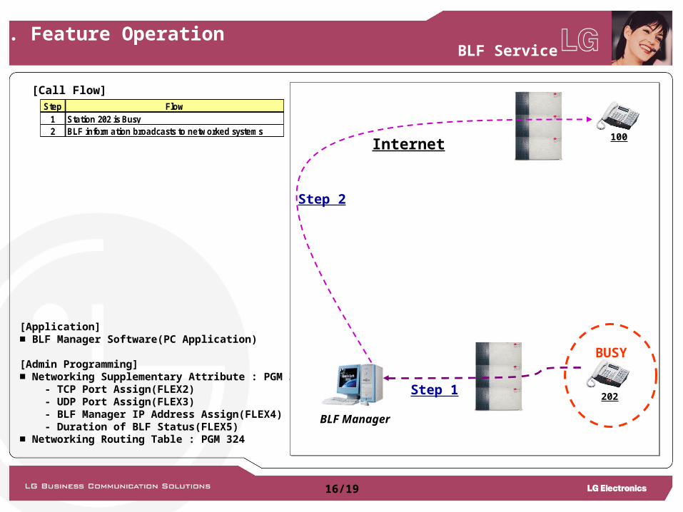
[Application]■ BLF Manager Software(PC Application)
[Admin Programming]■ Networking Supplementary Attribute : PGM 321 - TCP Port Assign(FLEX2) - UDP Port Assign(FLEX3) - BLF Manager IP Address Assign(FLEX4) - Duration of BLF Status(FLEX5)■ Networking Routing Table : PGM 324
BLF Service
Internet
Step 1202
100
BUSY
BLF Manager
Step 2
[Call Flow]Step Flow
1 Station 202 is Busy2 BLF information broadcasts to networked systems
7. Feature Operation
16/19
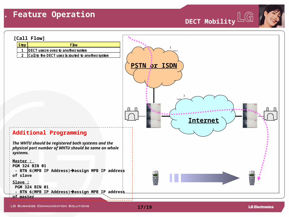
DECT Mobility
[Call Flow]
Internet
PSTN or ISDN
Step Flow1 DECT user moves to another system2 Call to the DECT user is routed to another system
Additional Programming
The WHTU should be registered both systems and thephysical port number of WHTU should be same on whole systems.
Master : PGM 324 BIN 01 - BTN 6(MPB IP Address)assign MPB IP address of slave Slave : PGM 324 BIN 01 - BTN 6(MPB IP Address)assign MPB IP address of master
7. Feature Operation
17/19
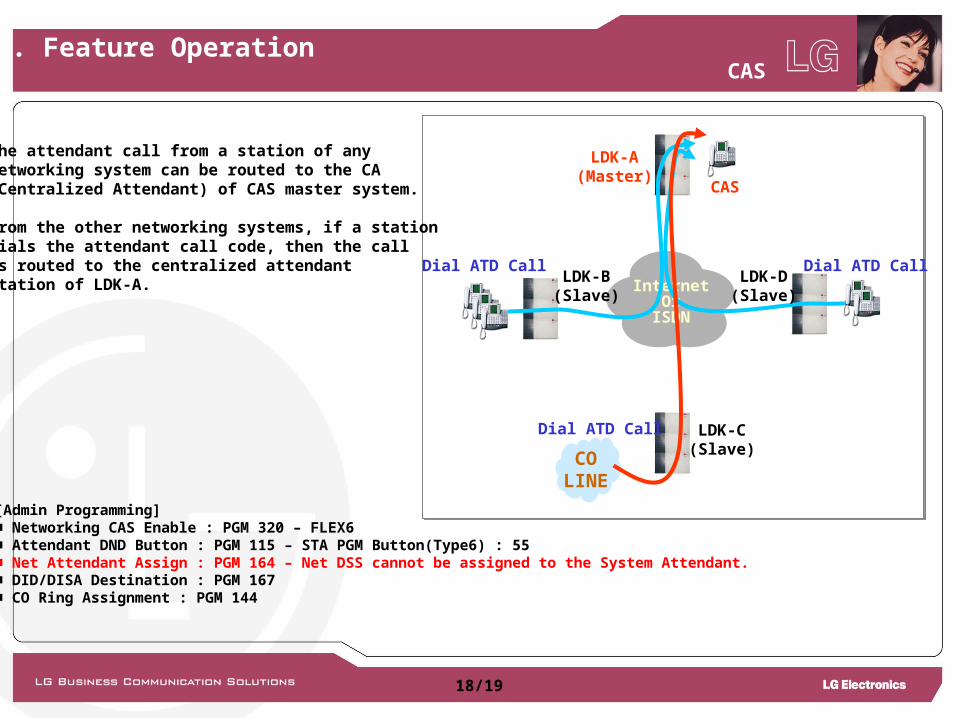
[Admin Programming]■ Networking CAS Enable : PGM 320 – FLEX6■ Attendant DND Button : PGM 115 – STA PGM Button(Type6) : 55■ Net Attendant Assign : PGM 164 – Net DSS cannot be assigned to the System Attendant.■ DID/DISA Destination : PGM 167■ CO Ring Assignment : PGM 144
InternetOr
ISDN
CAS
Dial ATD Call Dial ATD Call
COLINE
Dial ATD Call
LDK-A(Master)
LDK-D(Slave)
LDK-B(Slave)
LDK-C(Slave)
The attendant call from a station of any networking system can be routed to the CA(Centralized Attendant) of CAS master system. From the other networking systems, if a stationdials the attendant call code, then the call is routed to the centralized attendant station of LDK-A.
CAS7. Feature Operation
18/19
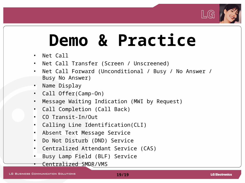
Demo & Practice• Net Call• Net Call Transfer (Screen / Unscreened)• Net Call Forward (Unconditional / Busy / No Answer / Busy No Answer)• Name Display• Call Offer(Camp-On)• Message Waiting Indication (MWI by Request)• Call Completion (Call Back)• CO Transit-In/Out• Calling Line Identification(CLI)• Absent Text Message Service• Do Not Disturb (DND) Service• Centralized Attendant Service (CAS)• Busy Lamp Field (BLF) Service• Centralized SMDR/VMS
19/19
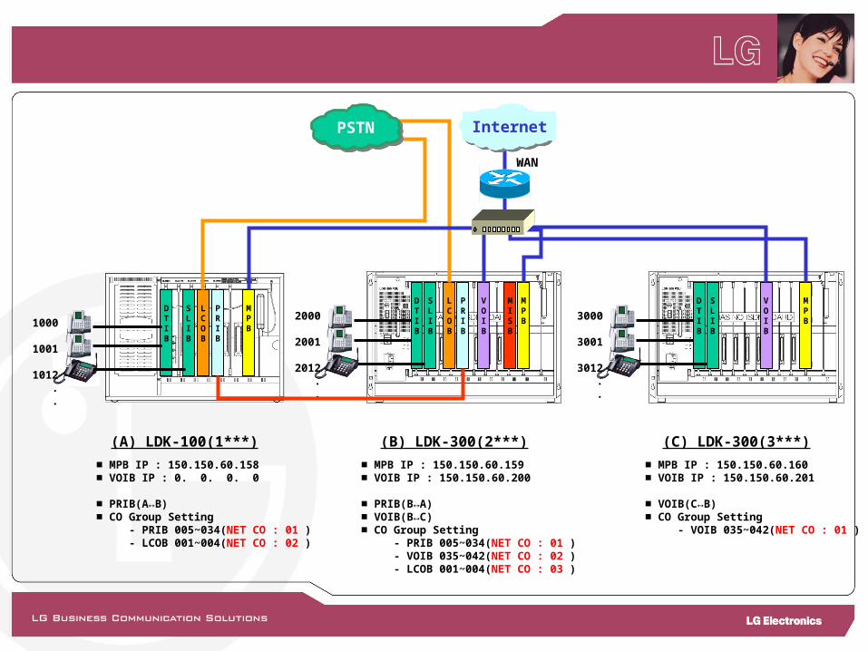
(A) LDK-100(1***) (B) LDK-300(2***) (C) LDK-300(3***)
WAN
Internet
MPB
DTIB
SLIB
LCOB
PRIB
VOIB
MISB
MPB
DTIB
SLIB
VOIB
2000
2001
2012 . .
3000
3001
3012 . .
■ MPB IP : 150.150.60.158■ VOIB IP : 0. 0. 0. 0
■ PRIB(A↔B)■ CO Group Setting - PRIB 005~034(NET CO : 01 ) - LCOB 001~004(NET CO : 02 )
■ MPB IP : 150.150.60.159■ VOIB IP : 150.150.60.200
■ PRIB(B↔A)■ VOIB(B↔C)■ CO Group Setting - PRIB 005~034(NET CO : 01 ) - VOIB 035~042(NET CO : 02 ) - LCOB 001~004(NET CO : 03 )
■ MPB IP : 150.150.60.160■ VOIB IP : 150.150.60.201
■ VOIB(C↔B)■ CO Group Setting - VOIB 035~042(NET CO : 01 )
MPB
DTIB
PRIB
SLIB
LCOB
PSTN
1000
1001
1012 . .
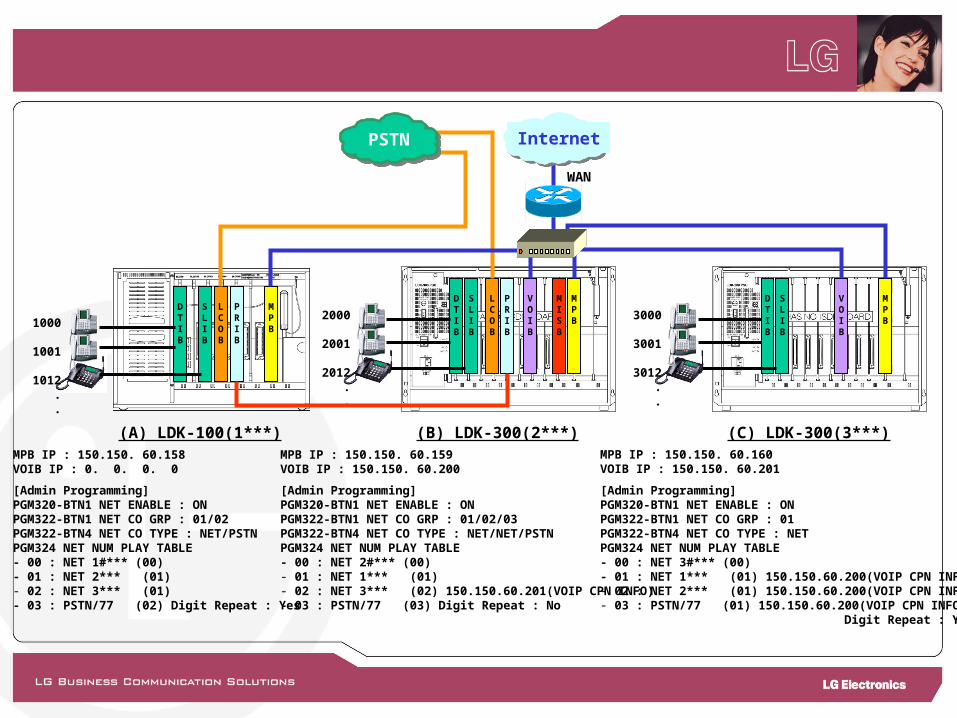
MPB IP : 150.150. 60.158VOIB IP : 0. 0. 0. 0
[Admin Programming]PGM320-BTN1 NET ENABLE : ONPGM322-BTN1 NET CO GRP : 01/02PGM322-BTN4 NET CO TYPE : NET/PSTNPGM324 NET NUM PLAY TABLE- 00 : NET 1#*** (00)- 01 : NET 2*** (01)- 02 : NET 3*** (01)- 03 : PSTN/77 (02) Digit Repeat : Yes
MPB IP : 150.150. 60.159VOIB IP : 150.150. 60.200
[Admin Programming]PGM320-BTN1 NET ENABLE : ONPGM322-BTN1 NET CO GRP : 01/02/03PGM322-BTN4 NET CO TYPE : NET/NET/PSTNPGM324 NET NUM PLAY TABLE- 00 : NET 2#*** (00)- 01 : NET 1*** (01) - 02 : NET 3*** (02) 150.150.60.201(VOIP CPN INFO)- 03 : PSTN/77 (03) Digit Repeat : No
MPB IP : 150.150. 60.160VOIB IP : 150.150. 60.201
[Admin Programming]PGM320-BTN1 NET ENABLE : ONPGM322-BTN1 NET CO GRP : 01PGM322-BTN4 NET CO TYPE : NETPGM324 NET NUM PLAY TABLE- 00 : NET 3#*** (00)- 01 : NET 1*** (01) 150.150.60.200(VOIP CPN INFO)- 02 : NET 2*** (01) 150.150.60.200(VOIP CPN INFO)- 03 : PSTN/77 (01) 150.150.60.200(VOIP CPN INFO) Digit Repeat : Yes
(A) LDK-100(1***) (B) LDK-300(2***) (C) LDK-300(3***)
WAN
Internet
MPB
DTIB
SLIB
LCOB
PRIB
VOIB
MISB
MPB
DTIB
SLIB
VOIB
2000
2001
2012 . .
3000
3001
3012 . .
MPB
DTIB
PRIB
SLIB
LCOB
PSTN
1000
1001
1012 . .

6. VoIP QSIG Connection
VoIP Connection between Systems
Master Slave
LAN
STA NO100 ~ 199
STA NO200 ~ 299
MPB
MPB
VOIB
VOIB
Network Configuration
7/19
LCOB4
PSTN
1. Station range : 100~1992. MPB IP Address : 192.168.23.103. VOIB IP Address : 192.168.23.214. CO Line type : (LCOB : Normal, VOIB : ISDN DID)5. DID Conversion Type : Type 16. CO Range : (LCOB : 1~4, VOIB : 5~12)7. Net CO Group : (VOIB : Net CO Group 01) (LCOB : Net CO Group 02)
1. Station range : 200~2992. MPB IP Address : 192.168.23.113. VOIB IP Address : 192.168.23.224. CO Line type : (VOIB : ISDN DID)5. DID Conversion Type : Type 16. CO Range : (VOIB : 1~8)7. Net CO Group : (VOIB : Net CO Group 01)
Master System
Slave System
“9” : CO Access Code
6. VoIP QSIG Connection
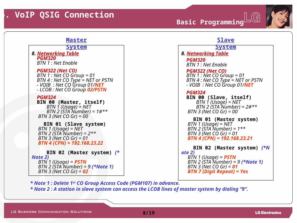
8. Networking Table PGM320 BTN 1 : Net Enable
PGM322 (Net CO) BTN 1 : Net CO Group = 01 BTN 4 : Net CO Type = NET or PSTN - VOIB : Net CO Group 01/NET - LCOB : Net CO Group 02/PSTN
PGM324 BIN 00 (Master, itself) BTN 1 (Usage) = NET BTN 2 (STA Number) = 1#** BTN 3 (Net CO Gr) = 00
BIN 01 (Slave system) BTN 1 (Usage) = NET BTN 2 (STA Number) = 2** BTN 3 (Net CO Gr) = 01 BTN 4 (CPN) = 192.168.23.22
BIN 02 (Master system) (*Note 2) BTN 1 (Usage) = PSTN BTN 2 (STA Number) = 9 (*Note 1) BTN 3 (Net CO Gr) = 02
8. Networking Table PGM320 BTN 1 : Net Enable PGM322 (Net CO) BTN 1 : Net CO Group = 01 BTN 4 : Net CO Type = NET or PSTN - VOIB : Net CO Group 01/NET
PGM324 BIN 00 (Slave, itself) BTN 1 (Usage) = NET BTN 2 (STA Number) = 2#** BTN 3 (Net CO Gr) = 00
BIN 01 (Master system) BTN 1 (Usage) = NET BTN 2 (STA Number) = 1** BTN 3 (Net CO Gr) = 01 BTN 4 (CPN) = 192.168.23.21
BIN 02 (Master system) (*Note 2) BTN 1 (Usage) = PSTN BTN 2 (STA Number) = 9 (*Note 1) BTN 3 (Net CO Gr) = 01 BTN 7 (Digit Repeat) = Yes
Basic Programming
Master System
Slave System
8/19
* Note 1 : Delete 1st CO Group Access Code (PGM107) in advance.* Note 2 : A station in slave system can access the LCOB lines of master system by dialing “9”.
IP Networking for VKX
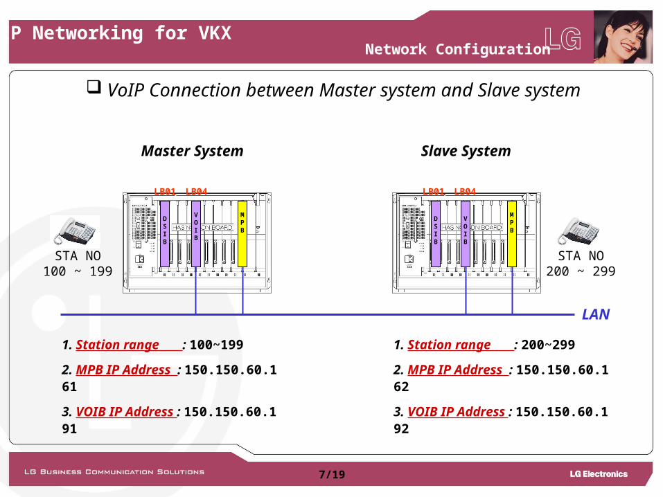
VoIP Connection between Master system and Slave system
Master System Slave System
LAN
STA NO100 ~ 199
STA NO200 ~ 299
MPB
MPB
VOIB
VOIB
Network Configuration
7/19
DSIB
DSIB
LB01 LB04 LB01 LB04
1. Station range : 100~199
2. MPB IP Address : 150.150.60.161
3. VOIB IP Address : 150.150.60.191
1. Station range : 200~299
2. MPB IP Address : 150.150.60.162
3. VOIB IP Address : 150.150.60.192
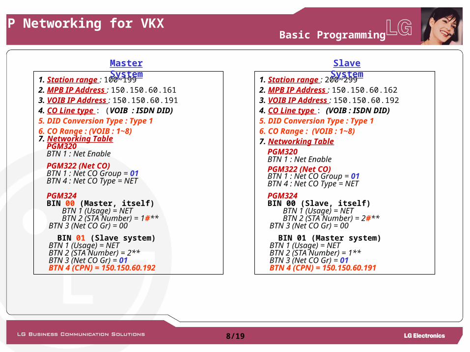
1. Station range : 100~1992. MPB IP Address : 150.150.60.1613. VOIB IP Address : 150.150.60.1914. CO Line type : (VOIB : ISDN DID)5. DID Conversion Type : Type 16. CO Range : (VOIB : 1~8)7. Networking Table PGM320 BTN 1 : Net Enable
PGM322 (Net CO) BTN 1 : Net CO Group = 01 BTN 4 : Net CO Type = NET PGM324 BIN 00 (Master, itself) BTN 1 (Usage) = NET BTN 2 (STA Number) = 1#** BTN 3 (Net CO Gr) = 00
BIN 01 (Slave system) BTN 1 (Usage) = NET BTN 2 (STA Number) = 2** BTN 3 (Net CO Gr) = 01 BTN 4 (CPN) = 150.150.60.192
1. Station range : 200~2992. MPB IP Address : 150.150.60.1623. VOIB IP Address : 150.150.60.1924. CO Line type : (VOIB : ISDN DID)5. DID Conversion Type : Type 16. CO Range : (VOIB : 1~8)7. Networking Table PGM320 BTN 1 : Net Enable PGM322 (Net CO) BTN 1 : Net CO Group = 01 BTN 4 : Net CO Type = NET
PGM324 BIN 00 (Slave, itself) BTN 1 (Usage) = NET BTN 2 (STA Number) = 2#** BTN 3 (Net CO Gr) = 00
BIN 01 (Master system) BTN 1 (Usage) = NET BTN 2 (STA Number) = 1** BTN 3 (Net CO Gr) = 01 BTN 4 (CPN) = 150.150.60.191
Basic Programming
Master System
Slave System
8/19
IP Networking for VKX