qos ethernet e vlans - instituto superior de engenharia do...
TRANSCRIPT

1
Virtual LANs
Miguel Leitão, 2018
VLANs
• Estruturam a rede de forma independente da estrutura física.
• Permitem agrupar utilizadores em função de politicas específicas,
independentes da localização física.

2
Segmentação tradicional
Sem VLANs:
Domínios de difusão são definidos pela estrutura física da
rede, normalmanete em função da localização geográfica.
VLANs
Com VLANs:
Domínios de difusão podem ser definidos administrativamente,
sem restrições da estrutura física ou da localização geográfica.

3
VLAN Segmentation
Benefícios das VLANs
• Facilita a instalação de postos de trabalho.
• Facilita a mobilidade de postos de trabalho.
• Facilita a estrutuiração lógica da rede.
• Melhora o controlo de tráfego.
• Aumenta a segurança.

4
Tipos de VLANs
• Port-based (static)• Tipologia mais usada.
• Configuração simples.
• Portas são atribuídas individualmente ou em grupos.
• MAC address• Raramente utilizada.
• Administração pesada.
• Cada endereço MAC deve ser configurado individualmente.
• Permite soluções dinâmicas.
• Protocol based• Pouco comum.
• Associa endereços IP ou gamas de endereços.
Static VLANs
• Static VLANs work well when:
– Moves are controlled and managed.
– There is robust VLAN management software to configure
the ports.
– It is not desirable to assume the additional overhead
required when maintaining end-station MAC addresses.

5
Local VLANs
• Allow spliting switches into separate (virtual)
switches.
• Only members of a VLAN can see that VLAN’s traffic
– Inter-VLAN traffic must go through a router.
VLAN X VLAN Y
Switch
VLAN X nodes VLAN Y nodes
Edge ports(portas de acesso)
LANS Virtuais
• SEGMENTO = Domínio de Colisão– Os computadores de um Hub estão no mesmo segmento.
• VLAN = Domínio de Broadcast– O tráfego de broadcast pode passar de uma VLAN para outra apenas
através de um encaminhador.
A
SWITCH
B
C
D
FF.FF.FF.FF.FF.FF
FF.FF.FF.FF.FF.FF
FF.FF.FF.FF.FF.FF
E
A,B,C: VLAN 1
D,E: VLAN 2

6
Local VLANs
• 2 VLANs or more within a single switch.
• Edge ports, where end nodes are connected, are configured
as members of a VLAN.
• The switch behaves as several virtual switches, sending
traffic only within VLAN members.
• Switches may not bridge any traffic between VLANs, as this
would violate the integrity of the VLAN broadcast domain.
• Traffic between VLANs must be routed.
VLAN operation
• As a device enters the network, it automatically
assumes the VLAN membership of the port to which it
is attached.
• The default VLAN for every port in the switch is
VLAN 1 and cannot be deleted.
• All other ports on the switch may be reassigned to
alternate VLANs.

7
Interligação de Switches
SWITCH SWITCH
SWITCH
A
B
D
E
VLAN 1,2,3VLAN 1,2,3
VLAN 1,2,3VLAN 1
VLAN 2 VLAN 2
VLAN 3
VLAN 2
TRUNKACCESS
Link Trunk
Tráfego de Várias VLANs
IEEE 802.1Q
Interface de Acesso
Tráfego de uma única VLAN
IEEE 802.3
C
F
VLAN 1GVLAN 3
VLANs across switches
• VLAN tagging is used when a single link needs to
carry traffic for more than one VLAN.
No VLAN Tagging
VLAN Tagging

8
VLANs across switches
• Two switches can exchange traffic from one or more
VLANs.
• Inter-switch links can be configured as trunks,
carrying frames from all or a subset of a switch’s
VLANs.
• Each frame on a trunk carries a tag that identifies
which VLAN it belongs to.
Edge Ports Edge Ports
VLANs across switches
802.1Q Trunk
Tagged Frames
VLAN X VLAN YVLAN X VLAN Y
Trunk Port
This is called “VLAN Trunking” or “VLAN Tagging”
Trunk Port

9
Inter-Switch Link
Quadros Ethernet
MAC destino
(6 bytes)
MAC origem
(6 bytes)
Dados
(46 a 1500 bytes)
CRC
(4 bytes)
Ethernet I & II
Tipo Proto.
(2 bytes)
MAC destino
(6 bytes)
MAC origem
(6 bytes)
Dados
(46 a 1500 bytes)
CRC
(4 bytes)
IEEE 802.3Tamanho
(2 bytes)
>= 1536
< 1536
MAC destino
(6 bytes)
MAC origem
(6 bytes)
Dados
(46 a 1500 bytes)
CRC
(4 bytes)
IEEE 802.1Q
Tipo Proto
(2 bytes)
VLAN Tag
(2 bytes)
Tipo 802.1Q = 0x8100Prioridade (3 bits) + CFI (1bit) + VLANID (12 bits)
Tipo Proto
(2 bytes)

10
Protocolos Trunk
• Os quadros nas interfaces Trunk utilizam o formato IEEE 802.1Q.
• Cada quadro inclui identificador das VLANs que pertence.
DESTINO ORIGEM CFI Dados CRC
6 Bytes 6 Bytes
Esses campos são removidos
quando o quadro é enviado para
uma interface do tipo access.
TYPE
2 Bytes
PRIO
3 Bits
VLAN ID
1 Bit 12 Bits
PRIO: IEEE 802.1 P
CFI: Canonical Format Indicator
• 0 em redes Ethernet
TYPE
2 Bytes
0x8100
IEEE 802.1Q
• IEEE standard.
• Defines how Ethernet frames should be tagged when
moving across switch trunks.
• Switches from different vendors are able to exchange
VLAN traffic.

11
Modos das Portas de Switch
• As portas de um switch pode trabalhar nos modos:
– Modo Access• Cada porta do switch pertence a uma única VLAN.
• Quadros Ethernet: Formato Normal.
– Modo Trunk• Multiplexa o tráfego de múltiplas VLANs.
• Normalmente interconectam switches.
• Quadros Ethernet: formato especial (VLAN).
• Apenas computadores com placas especiais podem ser conectados.
Tagged vs. Untagged
• Edge ports are not tagged, they are just “members” of
a VLAN
• Frames in switch-to-switch links (trunks), when
transporting multiple VLANs, need to be tag.
• A trunk can transport both tagged and untagged
VLANs
– As long as the two switches agree on how to handle
those

12
Link Aggregation
Link Aggregation
• Also known as port bundling, link bundling
• You can use multiple links in parallel as a single,
logical link
– For increased capacity
– For redundancy (fault tolerance)
• LACP (Link Aggregation Control Protocol) is a
standardized method of negotiating these bundled
links between switches

13
LACP Operation
• Two switches connected via multiple links will send
LACPDU packets, identifying themselves and the port
capabilities
• They will then automatically build the logical
aggregated links, and then pass traffic.
• Switch ports can be configured as active or passive
LACP Operation
• Switches A and B are connected to each other using
two sets of Fast Ethernet ports
• LACP is enabled and the ports are turned on
• Switches start sending LACPDUs, then negotiate
how to set up the aggregation
Switch A Switch B
LACPDUs
100 Mbps
100 Mbps

14
LACP Operation
• The result is an aggregated 200 Mbps logical link
• The link is also fault tolerant: If one of the member
links fail, LACP will automatically take that link off the
bundle, and keep sending traffic over the remaining
link
200 Mbps logical link
Switch A Switch B
100 Mbps
100 Mbps
Distributing Traffic in Bundled Links
• Bundled links distribute frames using a hashing
algorithm, based on:
– Source and/or Destination MAC address
– Source and/or Destination IP address
– Source and/or Destination Port numbers
• This can lead to unbalanced use of the links,
depending on the nature of the traffic
• Always choose the load-balancing method that
provides the most distribution

15
Switching Loops
Switching Loop
• When there is more than one path between two
switches
• What are the potential problems?
Switch A Switch B
Swtich C

16
Switching Loop
Switch A Switch B
Swtich C
Node1 sends a
broadcast frame
(e.g. an ARP
request)
Node 1
Switching Loop
Switch A Switch B
Swtich C
Switches A, B
and C broadcast
node 1’s frame
out every port
Node 1

17
Switching Loop
Switch A Switch B
Swtich C
But they receive
each other’s
broadcasts, which
they need to forward
again out every port!
The broadcasts are
amplified, creating a
broadcast storm!
Node 1
Switching Loop
A B
C,D A,B
C D
• Os switches criam tabelas de encaminhamento escutando os endereços MAC de origem enviado para suas portas.

18
Cascateamento de Switches
A B
C,D,E,F
A,B
C D
E F
A,B,C,D
E,F
Cascateamento de Switches
A B
A,B,C,D,E,F
C D
E F
A,B,C,D,E,FA,B,C,D,E,F
A,B,C,D,E,F A,B,C,D,E,F
A,B,C,D,E,F

19
Switching Loops
If there is more than one path between two switches:
Forwarding tables become unstable
Source MAC addresses are repeatedly seen coming from
different ports
Switches will broadcast each other’s broadcasts
All available bandwidth is utilized
Switch processors cannot handle the load
Good Switching Loops???
• But you can take advantage of loops!
– Redundant paths improve resilience when:
• A switch fails
• Wiring breaks
• How to achieve redundancy without creating
dangerous traffic loops?

20
What is a Spanning Tree
• “Given a connected,
undirected graph, a
spanning tree of that
graph is a subgraph
which is a tree and
connects all the vertices
together”.
• A single graph can have
many different spanning
trees.
Spanning Tree Protocol
• The purpose of the protocol is to have bridges
dynamically discover a subset of the topology that is
loop-free (a tree) and yet has just enough
connectivity so that where physically possible, there
is a path between every switch.

21
Broadcast storm
• Broadcast traffic is carried across all trunks in a VLAN.
• A truck link carries broadcast traffic from several
VLANs.
• Broadcast storm can spread across the extent of the
VLAN.
• Maintenance and troubleshooting nightmare.
STP
• O STP utiliza mensagens BPDU:
– Bridge Protocol Data Unit
– Mensagens em Multicast (MAC)
• DE: 01:80:C2:00:00:00
• ATÉ: 01:80:C2:00:00:01
• STP funciona continuamente, de maneira a refletir mudanças
de topologia na rede.
– Se SPT está ativo, os pacotes BPDU são recebidos, mas não
encaminhados.
– Se SPT está desativado, os pacotes BPDU são encaminhados
como pacotes multicast genéricos.

22
Spanning Tree Protocol
• Several flavors:
– Traditional Spanning Tree (802.1d)
– Rapid Spanning Tree or RSTP (802.1w)
– Multiple Spanning Tree or MSTP (802.1s)
STP: Spanning-Tree
• O STP é executado em cada switch da rede
• Princípio:
– Entre 2 estações na rede só pode existir um caminho ativo.
– As portas que impliquem loops fechados devem ser bloqueadas.
• A estratégia consiste em escolher um switch como Root, e
construir uma árvore com o menor caminho até ao Root.

23
Topologia STP
A
B C
D
RP RP
RP
As portas na direção do root são
chamadas portas Root
As portas na direção oposta ao
root são chamadas portas
designadas.
Traditional Spanning Tree (802.1d)
• Switches exchange messages that allow them to
compute the Spanning Tree
– These messages are called BPDUs
(Bridge Protocol Data Units)
– Two types of BPDUs:
• Configuration
• Topology Change Notification (TCN)

24
BPDU: Padrão IEEE 802.1D
Traditional STP (802.1d)
• First Step:
– Decide on a point of reference: the Root Bridge
– The election process is based on the Bridge ID, which
is composed of:
• The Bridge Priority: A two-byte value that is configurable
• The MAC address: A unique, hardcoded address that cannot be
changed.

25
Root Bridge Selection (802.1d)
• Each switch starts by sending out BPDUs with a Root
Bridge ID equal to its own Bridge ID.
– I am the root!
• Received BPDUs are analyzed to see if a lower Root
Bridge ID is being announced.
– If so, each switch replaces the value of the advertised
Root Bridge ID with this new lower ID.
• Eventually, they all agree on who the Root Bridge is.
Root Bridge Selection (802.1d)
All switches have the same priority. Switch A has the lowest Id. Switch A becomes the Root.
Switch B Switch C
32678.0000000000AA
32678.0000000000BB 32678.0000000000CC
Switch A

26
Root Port Selection (802.1d)
• Now each switch needs to figure out where it is in
relation to the Root Bridge
– Each switch needs to determine its Root Port
– The key is to find the port with the lowest Root Path
Cost
• The cumulative cost of all the links leading to the Root Bridge
Root Port Selection (802.1d)
• Each link on a switch has a Path Cost
– Inversely proportional to the link speed
e.g. the faster the link, the lower the cost
Link Speed STP Cost
10 Mbps 100
100 Mbps 19
1 Gbps 4
10 Gbps 2

27
Root Port Selection (802.1d)
• Root Path Cost is the accumulation of a link’s Path
Cost and the Path Costs learned from neighboring
Switches.
– It answers the question: How much does it cost to
reach the Root Bridge through this port?
Root Port Selection (802.1d)
• Root Bridge sends out BPDUs with a Root Path Cost
value of 0
• Neighbor receives BPDU and adds port’s Path Cost
to Root Path Cost received
• Neighbor sends out BPDUs with new cumulative
value as Root Path Cost
• Other neighbor’s down the line keep adding in the
same fashion
28
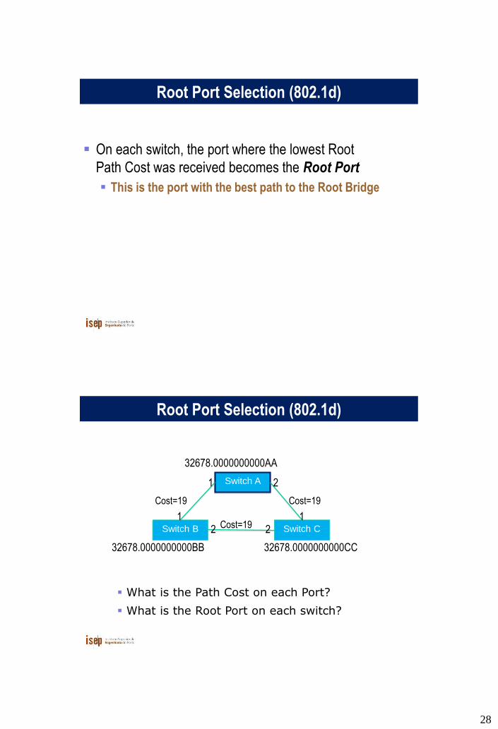
Root Port Selection (802.1d)
On each switch, the port where the lowest Root
Path Cost was received becomes the Root Port
This is the port with the best path to the Root Bridge
32678.0000000000BB 32678.0000000000CC
Root Port Selection (802.1d)
Cost=19 Cost=19
Cost=19
What is the Path Cost on each Port?
What is the Root Port on each switch?
Switch B Switch C
Switch A
32678.0000000000AA
1 2
1 12 2

29
32678.0000000000BB 32678.0000000000CC
Root Port Selection (802.1d)
Cost=19 Cost=19
Cost=19Switch B Switch C
Switch A
32678.0000000000AA
1 2
1 12 2
Root PortRoot Port
Electing Designated Ports (802.1d)
OK, we now have selected root ports but we haven’t
solved the loop problem yet, have we?The links are
still active!
Each network segment needs to have only one
switch forwarding traffic to and from that segment
Switches then need to identify one Designated
Port per link
The one with the lowest cumulative Root Path Cost
to the Root Bridge

30
32678.0000000000BB 32678.0000000000CC
Designeted Port Selection (802.1d)
Cost=19 Cost=19
Cost=19Switch B Switch C
Switch A
32678.0000000000AA
1 2
1 12 2
Which port should be the Designated Port on
each segment?
Electing Designated Ports (802.1d)
Two or more ports in a segment having identical
Root Path Costs is possible, which results in a tie
condition
All STP decisions are based on the following
sequence of conditions:
Lowest Root Bridge ID
Lowest Root Path Cost to Root Bridge
Lowest Sender Bridge ID
Lowest Sender Port ID

31
32678.0000000000BB 32678.0000000000CC
Root Port Selection (802.1d)
Cost=19 Cost=19
Cost=19Switch B Switch C
Switch A
32678.0000000000AA
1 2
1 12 2
Designated Port
Designated Port
Designated Port
In the B-C link, Switch B
has the lowest Bridge ID,
so port 2 in Switch B is the
Designated Port
Blocking a port
• Any port that is not elected as either a Root Port, nor
a Designated Port is put into the Blocking State.
• This step effectively breaks the loop and completes
the Spanning Tree.

32
32678.0000000000BB 32678.0000000000CC
Blocking a port
Cost=19 Cost=19
Cost=19Switch B Switch C
Switch A
32678.0000000000AA
1 2
1 12 2
Port 2 in Switch C is put into the Blocking State,
because it is neither a Root Port nor a
Designated Port
✗
Spanning Tree Protocol States
• Disabled
– Port is shut down
• Blocking
– Not forwarding frames
– Receiving BPDUs
• Listening
– Not forwarding frames
– Sending and receiving BPDUs

33
Spanning Tree Protocol States
• Learning
– Not forwarding frames
– Sending and receiving BPDUs
– Learning new MAC addresses
• Forwarding
– Forwarding frames
– Sending and receiving BPDUs
– Learning new MAC addresses
STP Topology Changes
• Switches will recalculate if:
– A new switch is introduced
• It could be the new Root Bridge!
– A switch fails
– A link fails

34
Root Bridge Placement
• Using default STP parameters might result in an
undesired situation
– Traffic will flow in non-optimal ways
– An unstable or slow switch might become the root
• You need to plan your assignment of bridge priorities
carefully
Bad Root Bridge Placement
Switch B
Switch C
Switch D32678.0000000000DD 32678.0000000000BB
32678.0000000000CC Switch A 32678.0000000000AA
Root Bridge
Out to router

35
Good Root Bridge Placement
Switch B
Switch C
Swtich D1.0000000000DD 0.0000000000BB
32678.0000000000CC Switch A 32678.0000000000AA
Alternative Root Bridge
Out to active router
Root Bridge
Out to standby router
Protecting the STP Topology
• Some vendors have included features that protect the
STP topology:
– Root Guard
– BPDU Guard
– Loop Guard
– UDLD
– Etc.

36
STP Design Guidelines
• Enable spanning tree even if you don’t have
redundant paths
• Always plan and set bridge priorities
– Make the root choice deterministic
– Include an alternative root bridge
• If possible, do not accept BPDUs on end user ports
802.1d Convergence Speeds
• Moving from the Blocking state to the Forwarding
State takes at least 2 x Forward Delay time units
(~ 30 secs.)
– This can be annoying when connecting end user
stations
• Some vendors have added enhancements such as
PortFast, which will reduce this time to a minimum for
edge ports
– Never use PortFast or similar in switch-to-switch links
• Topology changes typically take 30 seconds too
– This can be unacceptable in a production network

37
Rapid Spanning Tree (802.1w)
• Convergence is much faster
– Communication between switches is more interactive
• Edge ports don’t participate
– Edge ports transition to forwarding state immediately
– If BPDUs are received on an edge port, it becomes a
non-edge port to prevent loops
Rapid Spanning Tree (802.1w)
• Defines these port roles:
– Root Port (same as with 802.1d)
– Alternate Port
• A port with an alternate path to the root
– Designated Port (same as with 802.1d)
– Backup Port
• A backup/redundant path to a segment where another bridge
port already connects.

38
Rapid Spanning Tree (802.1w)
• Synchronization process uses a handshake method
– After a root is elected, the topology is built in cascade,
where each switch proposes to be the designated
bridge for each point-to-point link
– While this happens, all the downstream switch links
are blocking
Rapid Spanning Tree (802.1w)
Root
Switch
Proposal
Switch
Agreement
Switch
Switch
DP
RP

39
Rapid Spanning Tree (802.1w)
Root
Switch
Proposal
Switch
Agreement
Switch
Switch
DP
RP
DP
RP
Rapid Spanning Tree (802.1w)
Root
Switch
Proposal
Switch
Agreement
Switch
Switch
DP
RP
DP
RP
DP
RP

40
Rapid Spanning Tree (802.1w)
Root
Switch
Proposal
Switch
Agreement
Switch
Switch
DP
RP
DP
RP
DP
RP
DP
RP
Rapid Spanning Tree (802.1w)
• Prefer RSTP over STP if you want faster
convergence.
• Always define which ports are edge ports.

41
Multiple Spanning Tree (802.1s)
• Allows separate spanning trees per VLAN group
– Different topologies allow for load balancing between
links
– Each group of VLANs are assigned to an “instance” of
MST
• Compatible with STP and RSTP
Multiple Spanning Tree (802.1s)
Vlan A Vlan B
Root VLAN A Root VLAN B ✕
✕

42
VLANS increase complexity
• You can no longer “just replace” a switch
– Now you have VLAN configuration to maintain
– Field technicians need more skills
• You have to make sure that all the switch-to-switch
trunks are carrying all the necessary VLANs
– Need to keep in mind when adding/removing VLANs