qform extrusion 1
TRANSCRIPT
1,2 December 2012 Guangdong Aluminum Processing Technology International Seminar (APTIS) booth number 221, http://gdalu.alpc.org.cn/
Simulation and Optimization by QForm of Extrusion the Complex Thin Profiles
S. Stebunov1, N. Biba2, A. Lishny1, L. Jiao3
1)QuantorForm Ltd., Moscow, Russia2) MICAS Simulations Ltd., UK
3)IUIT, Beijing, China
ABSTRACT
The paper presents the development and practical implementation of the FE model for simulation of thin aluminium profile extrusion that is included in the special-purpose program QForm-Extrusion. Due to non-uniform material flow the profile that leaves the orifice may bend, twist or buckle. Other aspects of the material flow such as location of the seam welds in hollow profile extrusion and the propagation of the charge weld in billet-to-billet extrusion are also accurately predicted. The program has a special interface for quick die geometry import and automatic generation of the finite element model. The program automatically recognises bearing zones and converts them into parametric form allowing modification of bearing. Alterations and optimization can be done by using the special module “Bearing Editor” with which the user can achieve the most uniform distribution of longitudinal velocity. The simulation also provides comprehensive analysis of the die stress and deflection. Reasonable simulation time is provided by parallel computations. The software is currently in use at many die making and extrusion companies showing its high economic efficiency.
INTRODUCTION
QForm-Extrusion is a special-purpose program for aluminium profile extrusion simulation that has been developed by QuantorForm Ltd and it is based on the universal metal forming simulation program QForm3D. This specialised software includes Lagrange-Euler model for extrusion simulation at the steady state stage [1, 2]. The model is also based the assumption that the tool set is completely filled with the material prior to the beginning of the simulation thus the domain of the material flow inside of the tooling set does not change. This means that the mesh here is immovable while the material flows through it. This approach allows the program not to remesh the domain inside the tools but just to calculate the velocity of the nodes within it. On the other hand the free end of the profile increases in length very quickly after passing through the orifice. Due to non-uniform material flow the profile that leaves the orifice may bend, twist or buckle. The simulation is capable of predicting this undesirable shape deterioration and finding ways to minimize it. It is also very important that with such an approach it is possible to simulate the temperature evolution in the profile after it leaves the die and compare it with the actual temperature measurements that are available at certain distance from the die to tune some parameters of the process. Validation of the model has been performed for prediction of load, material flow pattern, profile temperature and die deformation using special model experiments and numerous industrial case studies done by the program users world-wide. Comprehensive analysis of the program accuracy has been done within the International Extrusion Benchmark Tests by means of comparison of the simulation results with precisely arranged experimental tests. Here the program has shown very good performance (see the tests in Bologna in 2007 [3], Dortmund in 2009 [4] and recently in Bologna in 2011 [5]).
BRIEF DESCRIPTION OF THE NUMERICAL MODEL OF EXTRUSION
From a practical point of view the most important stage of the extrusion process is the quasi steady-state stage when the product shape and its properties are formed. During this quasi steady-state stage some parameters such as the temperature and load do vary due to reducing of the billet length in the container
1,2 December 2012 Guangdong Aluminum Processing Technology International Seminar (APTIS) booth number 221, http://gdalu.alpc.org.cn/and the heat exchange between extruded material and the tools but this variation can be taken into account by the model still having the same Euler mesh in the extrusion die area. Generally the source data for extrusion simulation include:
The geometric models of the die set originally created in some Computer-Aided Design (CAD) system.
The properties of the extruded material (the flow stress data and thermal properties). The conditions on the contact surface of the extruded material with the tools (friction, heat transfer
coefficient, and temperature of the tools). The process parameters (initial temperature of the billet and its distribution, extrusion speed and
pulling force).The simulation of the extrusion process in our program is performed within a so-called simulation
domain. The simulation domain is the volume of the extruded material that partially fills the container and completely fills the inner space of the die assembly up to the exit from the bearing. The die set for solid profile extrusions generally includes the feeder or mandrel, the die, the backer and the bolster. Sometimes there may be no feeder at all or the feeder and the die can be made as a single tool. In the case of a hollow profile extrusion, the tooling set includes the mandrel, the die cap, the backer and the bolster. Semi hollow tooling design can be done according to open die or closed die scheme depending on the profile specifics.
In both cases the tooling set is eventually assembled with the container. Thus the extruded material fills the space inside the container and has the contact only with the feeder and the die (solid profile) and with the die cap and the mandrel (hollow profile). The other parts of the die assembly (the backer and the bolster and some other parts) have no direct contact with the material and are not used to create the simulation domain. Their design and properties are only taken into account when simulating the die stress and its deflection.
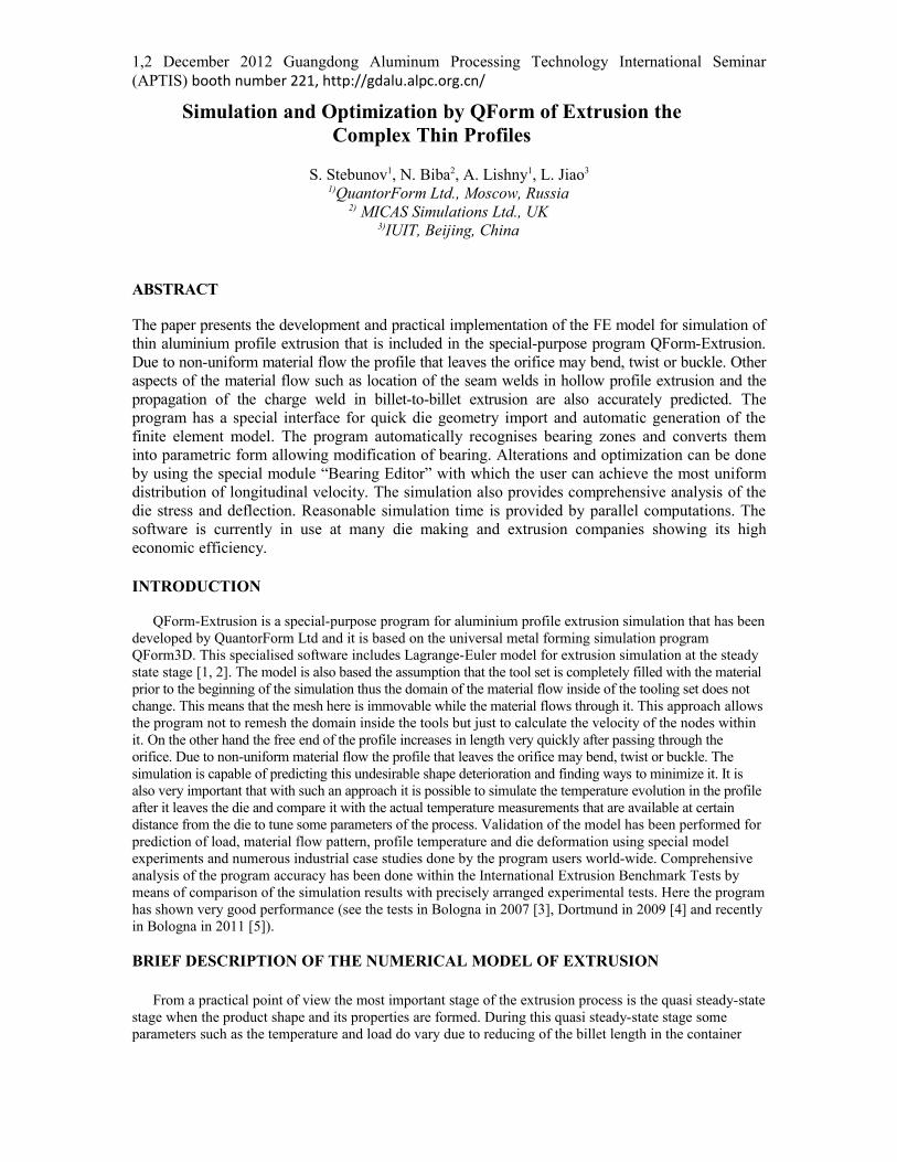
As a typical example of the model preparation in QForm-Extrusion let us consider the experimental die set used for scientific benchmark test presented in Bologna in October 2011. The details of the process and the die design can be found in [5]. The process includes parallel simulation of two similar hollow profiles having big variation of the wall thickness while the die has different design of welding chambers as well as either full or partial support of the die tongue for each of the profile. The profile drawing and stages of the model creation are shown in Fig. 1
(a) (b) (c)
(d) (e)
Fig. 1. The scheme of the hollow profiles proposed for scientific benchmark test (a) and subsequent stages of the model preparation in QForm-Extrusion: the tool set imported from CAD system (b); the mesh in the

1,2 December 2012 Guangdong Aluminum Processing Technology International Seminar (APTIS) booth number 221, http://gdalu.alpc.org.cn/tool set (c); the simulation domain with the mesh (d), the whole assembly with the mesh ready for simulation (e).
The mesh inside the domain is built using tetrahedral elements. The quality of the finite element mesh is critical to obtain accurate results. Mesh of insufficient density or with too big a gradient of the element size may cause non-convergence problem and deteriorate the quality of the simulation. It is especially critical if the mesh has improper density distribution at the entrance to the bearing area where the most intensive deformation takes place. In QForm-Extrusion such mesh optimisation is performed automatically without user intervention and it provides necessary background for accurate simulation of the process.
For accurate prediction of the material flow in extrusion process it is also necessary to take into account realistic friction and heat transfer conditions between extruded material and the tooling set. Numerous experimental and theoretical studies show that friction traction on the interface between the tool and deformed material can be represented as a combination of adhesive friction force and the force that is required to deform surface asperities. Thus the expression for friction traction in general can be written as follows:
T = Ta + Td . (1)Where
T is the total friction traction,Ta is the force required to break the adhesive links
Td is the force required to deform the asperities.The adhesive friction component is caused by molecular links of different nature between the body
surfaces and is dependent on the material’s physical properties. The deformation component is required to deform the asperities and depends on the roughness of the surfaces, flow stress of the deformed material, contact normal pressure and sliding velocity. At high contact pressure the deformation component Td is predominant while when the normal pressure is small the adhesive component is relatively more influential.
Depending on the value of the normal contact stress it is necessary to apply different mechanisms of friction as it is explained in our work [6]. Particularly in aluminium extrusions we can clearly distinguish two different areas with respect to friction conditions. The first area covers the inner surface of the container, feeding channels and pockets. Here the contact pressure is very high and the deformation friction factor is close to 1. Due to additional effect of the adhesive friction the total friction traction formally can be bigger than shearing flow stress. This means that the metal sticks to the surface of the tooling set and sliding takes place inside the deformed material by intensive shearing deformation.
The second contact area is the bearing area that can be visible in Bearing Editor of QForm-Extrusion program during the data preparation when it is represented in parametric form (Fig. 2). In this area we in turn distinguish three zones with different friction models:
1. The sticking zone with predominantly deformation friction. It is situated at the entrance to the bearing and may extend when the bearing has a choke angle.
2. The sliding zone where deformation friction decreases.3. The zone where the material may separate from the die due to small normal contact stress.
(a) (b) (c)Fig. 2. The contact area subject to transient friction conditions as it is seen in the Bearing Editor (a), the draft of the bearing line (b) and profile extruded after applying the boundary conditions in QForm-Extrusion program (c).
1,2 December 2012 Guangdong Aluminum Processing Technology International Seminar (APTIS) booth number 221, http://gdalu.alpc.org.cn/
Relative dimensions of these zones depend on several parameters and may vary along the profile perimeter. The division of the bearing into zones and some of the relations between them have been experimentally proved by S. Abtahi [7]. Thus for every point along the profile perimeter the following parameters may influence the extent of the zones:
• Actual (effective) choke angle• Actual thickness of the profile• Velocity of the profile flow.
The effective choke angle is the algebraic sum of the choke angle as it was originally manufactured in the die and the angle of the bearing surface inclination that appears due to tool deformation. The profile thickness also may vary due to the die deformation. Thus to get the precise results of the material flow we need to take into account the variation of the effective choke angle and the actual thickness of the profile. To get these values the material flow problem is to be coupled with the simulation of the tool deformation. Now the friction model developed in QForm-Extrusion includes the influence of the elastic deformation of the tooling set on the effective angle and the profile thickness [6].
Such a complicated friction model cannot be expressed analytically thus it is realized as an iterative semi empiric algorithm. Firstly we simulate the material flow and solve the die deformation problem. Then we calculate effective choke angle and actual profile thickness at every point of the bearing perimeter and solve the material flow problem again. For every zone in every point of the bearing perimeter we calculate the friction stress depending on velocity, normal contact stress and flow stress.
MATERIAL FLOW AND THE MODEL VERIFICATION
The numerical model described above has been tested using both dedicated laboratory tests and cases from routine industrial practice. One of the most recent laboratory tests has been done within the conference ICEB 2011 and its results have been reported by us in [8]. The data summary and experimental results presented by the organisers can be found in [5]. The profile sketch and the tooling set are shown in Fig. 1 while here we would like to discuss some results on the material flow prediction.
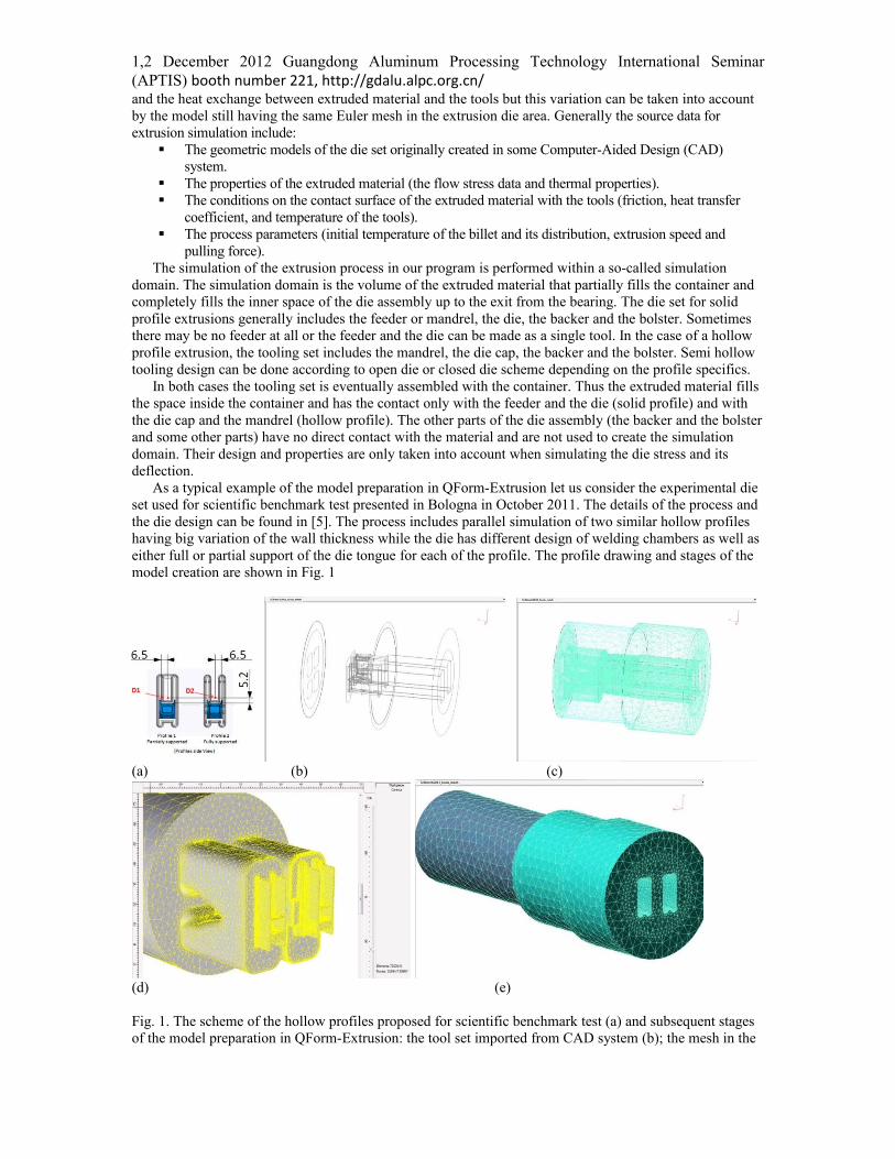
As seen from the simulation results the profile 1 tends to go much faster than the profile 2 (Fig.3 a and b). In the same time the simulation shows that due to different design of the welding chambers and other parts of the dies the profile 1 (on the left) has the trend to be bent downwards while the profile 2 is going more or less straight. The experimental data when have been disclosed at the conference have shown exactly the same trend in real material flow. The front pieces of the profiles are shown on the photos (Fig. 3, c and d) and are in good agreement with predictions. The same good correspondence with experiment has been observed in predicting the relative velocity of the profiles 1 and 2, the extrusion load, the profile temperature and the die deformation that can be found in [5] and [8].
a) b)
c) d)Fig. 3. The simulation of the profiles flow in the test: (a) – free flow of the profiles with the velocity
distribution, bending is shown; (b) – the same profiles simulation when the guides are applied to prevent

1,2 December 2012 Guangdong Aluminum Processing Technology International Seminar (APTIS) booth number 221, http://gdalu.alpc.org.cn/profiles bending; (c) - photo of the profile 1 that bends downwards; (d) - photo of the profile 2 going mostly straight.
COUPLED SIMULATION AND INDUSTRIAL IMPLEMENTATION
Industrial verification of the model was done using a wide range of solid and hollow profiles of various complexity and extrusion ratios that are produced by different users of QForm-Extrusion. It was found that when simulating the most complicated thin profiles it is very important to take into account elastic deformation of the tool set and especially deformation of the mandrel and die cap in bearing area. It means that the material flow and the die deformation should be considered as a coupled problem. Let us compare the non-coupled and coupled simulation of the material flow of the profile that shown on Fig 4a.
a) b) c)
Fig.4 .Actual double tube profile tip1(a), mandrel (b) and die cap (c) that are designed for this profile extrusion
In coupled simulation of the profile extrusion we consider the assembly of the tool set that may have different components like shown on Fig. 5.
1 With kind permission of ALMAK aluminium, Turkey
1,2 December 2012 Guangdong Aluminum Processing Technology International Seminar (APTIS) booth number 221, http://gdalu.alpc.org.cn/
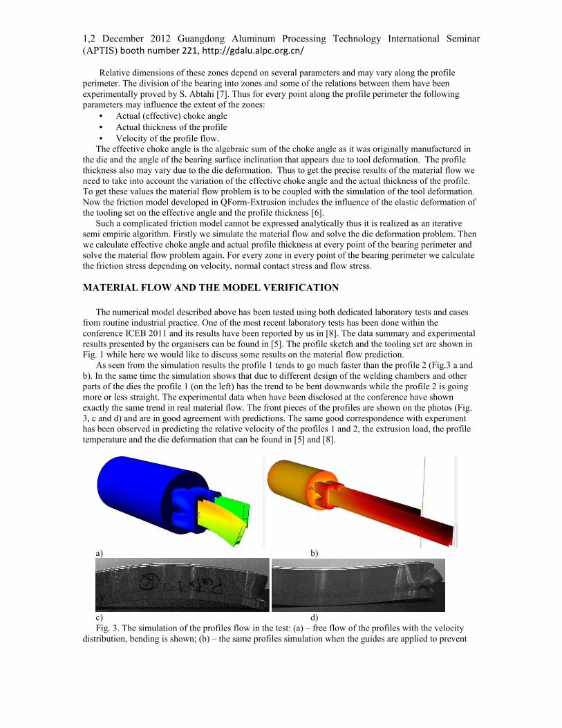
Fig.5.Typical tools set arrangement2 The tool set that was used for this case study includes all the components except a container that was replaced by appropriate boundary conditions on the billet side surface. Fig. 6 shows the Extrusion Domain and Tool Set Domain that were used for coupled simulation of the material flow the double tubes profile.
Fig.6. The Extrusion Domain and Tool Set Domain ready for simulation of the double tube profile
It is impossible to measure the velocity distribution along the profile contour in a real extrusion. Thus the only way is to compare the shape of the front tip of a real profile with the shape of its front end predicted in simulation. The shape of the front tip clearly shows inequality of the velocity in different parts of the profile. There were several goals of such industrial investigation:
• Testing and improving the methods of the geometry data transfer from industrial systems of die design into the simulation program.
• Estimation of the accuracy of the simulation. • Use the results of the tests for further development of the numerical model and the software.
The results obtained in these tests have shown that it is very important to consider the coupled elastic deformation of the tool set with plastic material flow. In the first computer trial it was simulated as the material flow through the rigid tool set (mandrel and die cap). The results have shown that the central part of the double tube profile in the die orifice goes slower than the outer part of the profile as shown in the Fig. 7a.
The simulation of the same extrusion case taking into account the elastic deformation of the tool set has shown the opposite material flow pattern with the inner part going faster. The front tip obtained in this computer trial is shown on Fig. 7b and looks very similar to the real front tip shown on the photo (Fig. 7c).
2 With kind permission COMPES S.p.a, Italy
Tool Set Domain
Extrusion Domain
1,2 December 2012 Guangdong Aluminum Processing Technology International Seminar (APTIS) booth number 221, http://gdalu.alpc.org.cn/
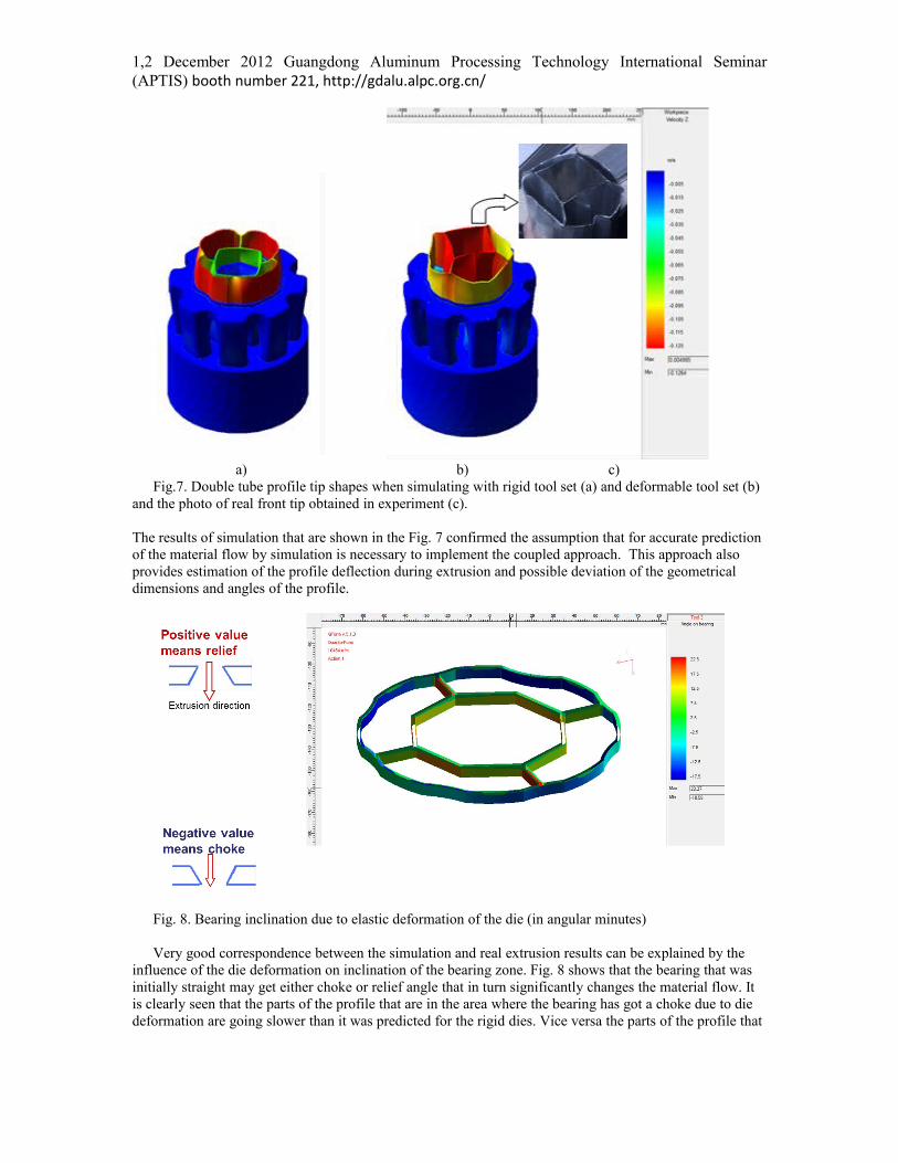
a) b) c)Fig.7. Double tube profile tip shapes when simulating with rigid tool set (a) and deformable tool set (b)
and the photo of real front tip obtained in experiment (c).
The results of simulation that are shown in the Fig. 7 confirmed the assumption that for accurate prediction of the material flow by simulation is necessary to implement the coupled approach. This approach also provides estimation of the profile deflection during extrusion and possible deviation of the geometrical dimensions and angles of the profile.
Fig. 8. Bearing inclination due to elastic deformation of the die (in angular minutes)
Very good correspondence between the simulation and real extrusion results can be explained by the influence of the die deformation on inclination of the bearing zone. Fig. 8 shows that the bearing that was initially straight may get either choke or relief angle that in turn significantly changes the material flow. It is clearly seen that the parts of the profile that are in the area where the bearing has got a choke due to die deformation are going slower than it was predicted for the rigid dies. Vice versa the parts of the profile that
1,2 December 2012 Guangdong Aluminum Processing Technology International Seminar (APTIS) booth number 221, http://gdalu.alpc.org.cn/are in relief area are going faster. Altogether it causes the effect that was illustrated by the material flow patterns on Fig. 7.
PREDICTION OF SEAM WELDS AND CHARGE WELDS IN EXTRUSION
Besides of the profile shape accuracy there are some other aspects of the product quality also related to the material flow pattern. Actually there are three types of defects that have to be avoided in extrusion practice: contamination of billet skin and its penetration in the product known as back-end-defect, improper location of seam welds (longitudinal welds) in hollow profiles and too much extended charge welds transition (transversal welds) between an old and a new billet in billet-to-billet extrusion. All these phenomena can be successfully predicted and corrected or at least minimized by means of simulation as it is illustrated by the examples proved by laboratory and industrial tests below.
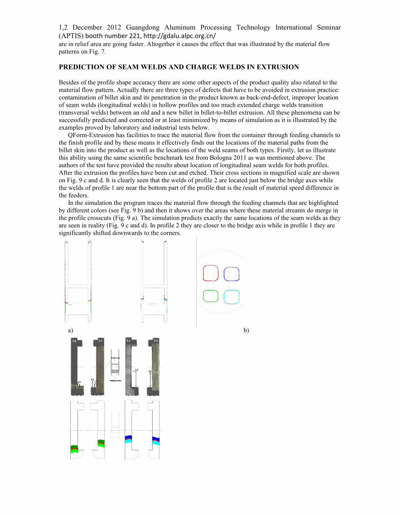
QForm-Extrusion has facilities to trace the material flow from the container through feeding channels to the finish profile and by these means it effectively finds out the locations of the material paths from the billet skin into the product as well as the locations of the weld seams of both types. Firstly, let us illustrate this ability using the same scientific benchmark test from Bologna 2011 as was mentioned above. The authors of the test have provided the results about location of longitudinal seam welds for both profiles. After the extrusion the profiles have been cut and etched. Their cross sections in magnified scale are shown on Fig. 9 с and d. It is clearly seen that the welds of profile 2 are located just below the bridge axes while the welds of profile 1 are near the bottom part of the profile that is the result of material speed difference in the feeders.
In the simulation the program traces the material flow through the feeding channels that are highlighted by different colors (see Fig. 9 b) and then it shows over the areas where these material streams do merge in the profile crosscuts (Fig. 9 a). The simulation predicts exactly the same locations of the seam welds as they are seen in reality (Fig. 9 с and d). In profile 2 they are closer to the bridge axis while in profile 1 they are significantly shifted downwards to the corners.
a) b)

1,2 December 2012 Guangdong Aluminum Processing Technology International Seminar (APTIS) booth number 221, http://gdalu.alpc.org.cn/
c) d)Fig. 9. The location of the seam welds obtained in simulation (a) and contours of feeding channels overlapped over the profile contours (b). Comparison of the seam weld locations in magnified scale for profile 1 (c) and profile 2 (d) obtained experimentally (photos above) and by means of simulation (below).
The seam weld position is very important for industrial profiles. Meanwhile due to their shape complexity it is very difficult to predict a priori where the welds may appear. Non proper position of the welding lines may even cause crash of constructions where such profiles are used. To check the accuracy of the seam weld prediction for more complicated industrial profiles several examples have been used and checked. One of them is presented in the Fig. 103. As clearly seen from this comparison the prediction is accurate enough to be used for routine check of the profiles at the stage of the tooling design to avoid possible problems due to inappropriate seam weld location.
a) b)
c)Fig. 10. Experimental (a), predicted (b) locations of the seam welds and location of feeding channels in the tooling set shown over the profile contour (c)
Charge or transverse welds are generated between the old and the new billet during continuous extrusion. On the contrary to seam welds the charge welds usually contain contamination of oxides or other substances that are responsible for lower mechanical properties along them. Thus charge welds are to be discarded from the finish profile. In industrial practice quite often it is not easy to find their positions and costly microstructure investigations are to be done.
3) With kind permission of COMPES, Italy

1,2 December 2012 Guangdong Aluminum Processing Technology International Seminar (APTIS) booth number 221, http://gdalu.alpc.org.cn/The accuracy of the model prediction capabilities for transverse welds has been tested using an industrial example proposed by SAPA Technology (Sweden). To show the propagation of the transversal seam weld inside the extruded profile the charge plane is to be specified. This plane initially separates new and old material. The pictures in Fig. 11 show propagation of the material from a “new” billet through “old” one.
a) b)Fig. 11. General view of the extruded profile (a) and the progress of propagation of the new billet material (red) into the product (b).
More comprehensive view of the charge weld and its comparison with experimental data is shown on Fig. 12. The crosscuts show how “new” material expands through the profile during the progress of the extrusion. The comparison has shown the high accuracy of the numerical prediction.
a)
b)Fig. 12. New material shown by red colour in the extruded profile predicted in simulation (left) and the photos of etched crosscuts (right) for the same different positions (a and b)4.
CONCLUSIONS
1. Extrusion simulation model included in QForm-Extrusion program is based on Lagrange-Euler approach with specially optimized finite element mesh in the simulation domain.
2. Aluminium extrusion model requires consideration of more complicated friction law that includes the influence of adhesion friction.
3. The program has validated by model and industrial experiments showing good accuracy of the results in terms of material flow prediction, the actual profile shape and other vital process parameters.
4. Accurate prediction of the material flow allows analyzing of longitudinal and transversal seam welds that often are critical for the product quality and are to be optimized at the stage of the tool design.
5. The program is an ideal tool for wide range of industrial and research implementations in the field of thin profile extrusion.
4) With kind permission of SAPA Technology, Sweden

1,2 December 2012 Guangdong Aluminum Processing Technology International Seminar (APTIS) booth number 221, http://gdalu.alpc.org.cn/
REFERENCES
1) N. Biba, S. Stebunov, A. Vlasov, “Application of QForm Program for Improvement of the Die Design and Profile Extrusion Technology” in Proceedings of the Ninth International Aluminum Extrusion Technology Seminar & Exposition, Orlando, USA, 20082) S. Stebunov, A. Lishnij, N. Biba, “Development and industrial verification of QForm-Extrusion program for simulation profile extrusion” in Proceeding of International Conference on Extrusion and Benchmark, Dortmund, Germany, 2009, pp. 41-42.3) L. Donati, L. Tomesani, M. Schikorra, E. Tekkaya, “Extrusion Benchmark 2007” in Proceedings of the Conference Latest Advances in Extrusion Technology and Simulation in Europe, Bologna, 2007, pp. 89-95.4) D. Pietzka, N. Ben Khalifa, L.Donati, L. Tomesani, E. Tekkaya, “Extrusion Benchmark 2009. Experimental analysis of deflection in extruded dies” in Advances on Hot Extrusion and Simulation of Light Alloys, Dortmund, Germany, 2009, pp. 19-26.5) A. Selvaggio, A. Segatori, A. Guzel, L. Donati, L. Tomesani, E. Tekkaya, “Extrusion Benchmark 2011: Evaluation of different design strategies on process conditions, die deflection and seam weld quality in hollow profiles” in Progress in Extrusion Technology and Simulation of Light Metal Alloys, Bologna, Italy, 2011, pp. 1-10. 6) N. Biba, S. Stebunov, A. Lishnij, “Influence of contact friction conditions on thin profile simulation accuracy” in Progress in Extrusion Technology and Simulation of Light Metal Alloys, Bologna, Italy, 2011, pp. 35-427) S. Abtahi, “Friction and Interface Reactions on the Die Land in Thin-Walled Extrusion,” Ph. D. Thesis, Norwegian Institute of Technology, Trondheim, Norway, 1995.8) N. Biba, S. Stebunov, A. Lishnij, “QForm-Extrusion data form scientific” in Latest Advances in Extrusion Technology and Simulation and 4th Extrusion Benchmark, Bologna, Italy, 2011, pp. 201-207