qcvn 15:2010/btttt quy chu Ẩn kỸ thuẬt quỐc gia...
TRANSCRIPT

CỘNG HOÀ XÃ HỘI CHỦ NGHĨA VIỆT NAM
QCVN 15:2010/BTTTT
QUY CHUẨN KỸ THUẬT QUỐC GIA VỀ THIẾT BỊ ĐẦU CUỐI THÔNG TIN DI ĐỘNG W-CDMA FDD
National technical regulation on Mobile Stations for W-CDMA FDD
(for information only)
HANOI - 2010

QCVN 15:2010/BTTTT
2
Table of contents
Foreword
1. 1. GENERAL ....................................................................................................... 5
1.1. Scope ........................................................................................................... 5
1.2. Subjects of application ................................. Error! Bookmark not defined.
1.3. Normative references ................................... Error! Bookmark not defined.
1.4. Definitions .................................................... Error! Bookmark not defined.
1.5. Symbols ....................................................... Error! Bookmark not defined.
1.6. Abbreviations .............................................. Error! Bookmark not defined.
2. TECHNICAL REQUIREMENTS .......................... Error! Bookmark not defined.
2.1. Environmental profile ................................... Error! Bookmark not defined.
2.2. Conformance requirements.......................... Error! Bookmark not defined.
2.2.1. Essential parameters and corresponding technical requirements. Error! Bookmark not defined.
2.2.2. Transmitter maximum output power ..... Error! Bookmark not defined.
2.2.3. Transmitter spectrum emission mask ... Error! Bookmark not defined.
2.2.4. Transmitter spurious emissions ............ Error! Bookmark not defined.
2.2.5. Transmitter minimum output power ...... Error! Bookmark not defined.
2.2.6. Receiver adjacent channel selectivity ... Error! Bookmark not defined.
2.2.7. Receiver blocking characteristics .......... Error! Bookmark not defined.
2.2.8. Receiver spurious response ................. Error! Bookmark not defined.
2.2.9. Receiver intermodulation characteristicsError! Bookmark not defined.
2.2.10. Receiver spurious emissions .............. Error! Bookmark not defined.
2.2.11. Out-of-synchronization handling of output powerError! Bookmark not defined.
2.2.12. Transmitter Adjacent Channel Leakage power RatioError! Bookmark not defined.
2.2.13. Radiated emissions ............................ Error! Bookmark not defined.
2.2.14. Control and monitoring functions ........ Error! Bookmark not defined.
3. METHOD OF MEASUREMENT .......................... Error! Bookmark not defined.
3.1. Environmental conditions for testing ............ Error! Bookmark not defined.
3.2. Interpretation of the measurement results ... Error! Bookmark not defined.
3.3. Essential radio test suites ............................ Error! Bookmark not defined.
3.3.1. Transmitter maximum output power ..... Error! Bookmark not defined.
3.3.2. Transmitter spectrum emission mask ... Error! Bookmark not defined.
3.3.3. Transmitter spurious emissions ............ Error! Bookmark not defined.
3.3.4. Transmitter minimum output power ...... Error! Bookmark not defined.
QCVN 15:2010/BTTTT
3
3.3.5. Receiver adjacent channel selectivity (ACS)Error! Bookmark not defined.
3.3.6. Receiver blocking characteristics .......... Error! Bookmark not defined.
3.3.7. Receiver spurious response 27 ............. Error! Bookmark not defined.
3.3.8. Receiver Intermodulation characteristics 27Error! Bookmark not defined.
3.3.9. Receiver spurious emissions 28 ............ Error! Bookmark not defined.
3.3.10. Out-of-synchronization handling of output powerError! Bookmark not defined.
3.3.11. Transmitter adjacent channel leakage power ratio 29Error! Bookmark not defined.
3.3.12. Radiated emissions ............................. Error! Bookmark not defined.
3.3.13. Control and monitoring functions ......... Error! Bookmark not defined.
4. MANAGEMENT REGULATIONS ........................ Error! Bookmark not defined.
5. RESPONSIBILITY OF ORGANISATIONS/INDIVIDUALSError! Bookmark not defined.
6. IMPLEMENTATION ............................................. Error! Bookmark not defined.
Annex A (Informative) Environmental profile ........... Error! Bookmark not defined.
Annex B (Informative) Receiver sensitivity and correct operation of the equipment ................................................................................ Error! Bookmark not defined.
Annex C (Informative) Test Models ......................... Error! Bookmark not defined.
Annex D (Normative) DL reference measurement channel (12.2 kbps) and static propagation condition .............................................. Error! Bookmark not defined.
Annex E (Normative) UE Conformance Test Frequencies .... Error! Bookmark not defined.
Annex F (Informative) Generic Call Setup ProcedureError! Bookmark not defined.
Annex G (Normative) W-CDMA Modulated InterfererError! Bookmark not defined.

QCVN 15:2010/BTTTT
4
Foreword
QCVN 15:2010/BTTTT is based on the review and convert of
TCN 68-245:2006 "Mobile Stations for IMT-2000 CDMA Direct
Spread (W-CDMA FDD) - Technical Requirements", issued by
decision no 27/2006/QĐ-BBCVT dated July 25, 2006 of Minister
of Ministry of Post and Telecommunications (now the Ministry of
Information and Communications).
Technical Requirements of QCVN 15:2010/BTTTT accordance
with standards ETSI EN 301 908-2 V2.2.1 (2003-10) and EN 301
908-1 V2.2.1 (2003-10) of the European Telecommunications
Standards Institute (ETSI).
QCVN 15:2010/BTTTT is drafted by Research Institute of Posts
and Telecommunications (RIPT), verified and submitted by
Department of Science & Technology, issued by the Minister of
Information and Communications as in Circular No 18/2010/TT-
BTTTT dated July 30, 2010.

QCVN 15:2010/BTTTT
5
QUY CHUẨN KỸ THUẬT QUỐC GIA
VỀ THIẾT BỊ ĐẦU CUỐI THÔNG TIN DI ĐỘNG W-CDMA FDD
National technical regulation on Mobile Stations for W-CDMA FDD
1. GENERAL
1.1. Scope
This technical regulation applies to the User Equipment for IMT-2000 CDMA Direct Spread (UTRA FDD). This radio equipment type is capable of operating in all or any part of the frequency bands given in table 1.
Table 1 - CDMA Direct Spread service frequency bands (UTRA FDD)
Direction of transmission
CDMA Direct Spread service frequency bands (UTRA FDD )
Transmit 1920 MHz to 1980 MHz
Receive 2110 MHz to 2170 MHz
The Technical regulation applies to UTRA FDD User Equipments, including User Terminals supporting HS-PDSCH transmission using QPSK and 16 QAM Modulation.
Technical requirements of this Technical regulation ensure that the radio equipment shall be so constructed that it effectively uses the spectrum allocated to terrestrial/space radio communications and orbital resources so as to avoid harmful interference.
1.2. Subjects of application
This Technical regulation applies to all agencies, organizations, manufacturers, importer and operator User Equipments for use in the IMT-2000 CDMA Direct Spread (UTRA FDD).
1.3. Normative references
[1] ETSI EN 301 908-2 V2.2.1 (2003-10): “Electromagnetic compatibility and Radio spectrum Matters (ERM); Base Stations (BS), Repeaters and User Equipment (UE) for IMT-2000 Third-Generation cellular networks; Part 2: Harmonized EN for IMT-2000, CDMA Direct Spread (UTRA FDD) (UE) covering essential requirements of article 3.2 of R&TTE Directive”.
[2] ETSI EN 301 908-1 V2.2.1 (2003-10): “Electromagnetic compatibility and Radio spectrum Matters (ERM); Base Station (BS), Repeaters and User Equipment (UE) for IMT-2000 Third-Generation cellular networks; Part 1: Harmonized EN for IMT-2000, introduction and common requirements, covering essential requirements of article 3.2 of R&TTE Directive”.
1.4. Definitions
1.4.1. User Equipment

QCVN 15:2010/BTTTT
6
A Mobile Equipment with one or several UMTS Subscriber Identity Module(s). User
Equipment is a device allowing a user access to network services via the Uu
interface.
1.4.2. Ancillary equipment
Equipment (apparatus) used in connection with a User Equipment (UE) is considered
as an ancillary equipment (apparatus) if:
- The equipment is intended for use in conjunction with a User Equipment (UE) to
provide additional operational and/or control features to the radio equipment, (e.g.
to extend control to another position or location);
- The equipment cannot be used on a stand alone basis to provide user functions
independently of a UE; and
- The UE to which it is connected, is capable of providing some intended operation
such as transmitting and/or receiving without the ancillary equipment.
1.4.3. Environmental profile
Range of environmental conditions under which equipment within the scope of the
technical standard is required to comply with the provisions of the technical standard.
1.4.4. Maximum output power
Measure of the maximum power the UE can transmit (i.e. the actual power as would
be measured assuming no measurement error) in a bandwidth of at least (1 + α)
times the chip rate of the radio access mode.
NOTE: The period of measurement shall be at least one timeslot.
1.4.5. Mean power
Power (transmitted or received) in a bandwidth of at least (1+α) times the chip rate of
the radio access mode, when applied to a W-CDMA modulated signal.
NOTE: The period of measurement shall be at least one timeslot unless otherwise stated.
1.4.6. Nominal maximum output power
Nominal power defined by the UE power class.
1.4.7. Power spectral density
Function of power versus frequency and when integrated across a given bandwidth,
the function represents the mean power in such a bandwidth.
NOTE 1: When the mean power is normalized to (divided by) the chip-rate it represents the mean energy per chip. Some signals are directly defined in terms of energy per chip, (DPCH_Ec, Ec, OCNS_Ec and S-CCPCH_Ec)
and others defined in terms of PSD (Io, Ioc, Ior and I or). There also exist quantities that are a ratio of energy per chip to PSD (DPCH_Ec/Ior, Ec/Ior, etc.). This is the common practice of relating energy magnitudes in communication systems.
NOTE 2: It can be seen that if both energy magnitudes in the ratio are divided by time, the ratio is converted from
an energy ratio to a power ratio, which is more useful from a measurement point of view. It follows that an energy

QCVN 15:2010/BTTTT
7
per chip of X dBm/3.84 MHz can be expressed as a mean power per chip of X dBm. Similarly, a signal PSD of Y
dBm/3.84 MHz can be expressed as a signal power of Y dBm.
NOTE 3: The units of Power Spectral Density (PSD) are extensively used in the technical standard.
1.4.8. RRC filtered mean power
Mean power as measured through a root raised cosine filter with roll-off factor α and
a bandwidth equal to the chip rate of the radio access mode.
NOTE: The RRC filtered mean power of a perfectly modulated W-CDMA signal is 0.246 dB lower than the mean
power of the same signal.
1.4.9. IMT-2000
IMT-2000s are third generation mobile systems which are scheduled to start service
around the year 2000 subject to market considerations.
NOTE: ITU-R Recommendation M.8/BL/18 [24] identifies the detailed specifications for the IMT-2000 radio
interfaces.
1.4.10. Idle mode
State of User Equipment (UE) when switched on but with no Radio Resource Control
(RRC) connection.
1.4.11. Enclosure port
Physical boundary of the apparatus through which electromagnetic fields may radiate
or impinge.
NOTE: In the case of integral antenna equipment, this port is inseparable from the antenna port.
1.4.12. Port
Particular interface, of the specified equipment (apparatus), with the electromagnetic
environment.NOTE: For example, any connection point on an equipment intended for
connection of cables to or from that equipment is considered as a port (see figure 1).
Figure 1 - Examples of ports
1.4.13. Radio communications equipment
Telecommunications equipment which includes one or more transmitters and/or
receivers and/or parts thereof for use in a fixed, mobile or portable application.
NOTE: It can be operated with ancillary equipment but if so, is not dependent on it for basic functionality.
1.4.14. Signal and control port
Port which carries information or control signals, excluding antenna ports.

QCVN 15:2010/BTTTT
8
1.4.15. Telecommunication port
Port which is intended to be connected to telecommunication networks (e.g. public
switched telecommunication networks, integrated services digital networks), local
area networks (e.g. ethernet, token ring) and similar networks.
1.4.16. Traffic mode
State of user equipment (UE) when switched on and with Radio Resource Control
(RRC) connection established.
1.5. Symbols
α Roll-off factor of the root raised cosine filter, α = 0.22
DPCH_Ec Average energy per PN chip for DPCH
DPCH_Ec/Ior The ratio of the transmit energy per PN chip of the DPCH to
the total transmit power spectral density at the Node B antenna
connector (SS).
DPCCH_Ec/Ior The ratio of the transmit energy per PN chip of the DPCCH to
the total transmit power spectral density at the Node B antenna
connector (SS).
DPDCH_Ec/Ior The ratio of the transmit energy per PN chip of the DPDCH to
the total transmit power spectral density at the Node B antenna
connector (SS).
Ec Average energy per PN chip
Ec/Ior The ratio of the average transmit energy per PN chip for
different fields or physical channels to the total transmit power
spectral density.
Fuw Frequency of unwanted signal. This is specified in bracket in
terms of an absolute frequency(s) or a frequency offset from
the assigned channel frequency.
Ioac The power spectral density (integrated in a bandwidth of (1+α)
times the chip rate and normalized to the chip rate) of the
adjacent frequency channel as measured at the UE antenna
connector.
Ioc The power spectral density (integrated in a noise bandwidth
equal to the chip rate and normalized to the chip rate) of a
band limited white noise source (simulating interference from
cells, which are not defined in a test procedure) as measured
at the UE antenna connector.
Ior The total transmit power spectral density (integrated in a

QCVN 15:2010/BTTTT
9
bandwidth of (1+α) times the chip rate and normalized to the
chip rate) of the downlink signal at the Node B antenna
connector.
I or The received power spectral density (integrated in a bandwidth
of (1+α) times the chip rate and normalized to the chip rate) of
the downlink signal as measured at the UE antenna connector.
Iouw Unwanted signal power level.
1.6. Abbreviations
For the purposes of the present document, the following abbreviations apply:
16QAM 16-Quadrature Amplitude Modulation
ACLR Adjacent Channel Leakage power Ratio
ACS Adjacent Channel Selectivity
BER Bit Error Ratio
BLER Block Error Ratio
BS Base Station
CW Continuous Wave (unmodulated signal)
DCH Dedicated Channel
DL Down Link (forward link)
DPCH Dedicated Physical Channel
DPCCH Dedicated Physical Control Channel
DPDCH Dedicated Physical Data Channel
DTX Discontinuous Transmission
e.i.r.p equivalent isotropically radiated power
EMC ElectroMagnetic Compatibility
e.r.p effective radiated power
EUT Equipment Under Test
FACH Forward Access Channel
FDD Frequency Division Duplex
HS- High Speed Physical Downlink Shared Channel

QCVN 15:2010/BTTTT
10
PDSCH
Data rate Rate of the user information, which must be transmitted over the Air
Interface. For example, output rate of the voice codec.
LV Low Voltage
Node B A logical node responsible for radio transmission/reception in one or
more cells to/from the User Equipment
OCNS Orthogonal Channel Noise Simulator
QPSK Quadrature Phase Shift Keying
P-CCPCH Primary Common Control Physical Channel
PCH Paging Channel
P-CPICH Primary Common Pilot Channel
PICH Paging Indicator Channel
PN PseudoNoise
PSD Power Spectral Density
RF Radio Frequency
RRC Radio Resource Control
RRC Root Raised Cosine
R&TTE Radio equipment and Telecommunications Terminal Equipment
S-CCPCH Secondary Common Control Physical Channel
SCH Synchronization Channel
SS System Simulator
TDD Time Division Duplex
TFC Transport Format Combination
TFCI Transport Format Combination Indicator
TPC Transmit Power Control
UARFCN UTRA Absolute Radio Frequency Channel Number
UE User Equipment

QCVN 15:2010/BTTTT
11
UTRA Universal Terrestrial Radio Access
2. TECHNICAL REQUIREMENTS
2.1. Environmental profile
The technical requirements of the present document apply under the environmental
profile for operation of the equipment, which shall be declared by the supplier. The
equipment shall comply with all the technical requirements of the present document
at all times when operating within the boundary limits of the declared operational
environmental profile.
For guidance on how a supplier can declare the environmental profile see annex A.
2.2. Conformance requirements
2.2.1. Essential parameters and corresponding technical requirements
This technical standard identifies 9 essential parameters for IMT-2000 user
equipment (UE). Table 2 provides a cross reference between these 9 essential
parameters and the corresponding 13 technical requirements for equipment within
the scope of the present document.
Table 2 - Cross references
Essential parameter Corresponding technical requirements
Spectrum emissions mask 2.2.3 Transmitter Spectrum emissions mask
2.2.12 Transmitter adjacent channel leakage
power ratio
Conducted spurious emissions
in active mode
2.2.4 Transmitter spurious emissions
Accuracy of maximum output
power
2.2.2 Transmitter maximum output power
Prevention of harmful
interference through control of
power
2.2.5 Transmitter minimum output power
Conducted spurious emission in
idle mode
2.2.10 Receiver spurious emissions
Impact of interference on
receiver performance
2.2.7 Receiver Blocking characteristics
2.2.8 Receiver spurious response
2.2.9 Receiver Intermodulation characteristics

QCVN 15:2010/BTTTT
12
Receiver adjacent channel
selectivity
2.2.6 Receiver Adjacent Channel Selectivity
(ACS)
Control and Monitoring functions 2.2.11 Out of synchronization handling of
output power
2.2.14 Control and Monitoring functions
Radiated emissions 2.2.13 Radiated emissions
2.2.2. Transmitter maximum output power
2.2.2.1. Definition
The nominal maximum output power and its tolerance are defined according to the
power class of the UE.
The nominal power defined is the transmit power of the UE, i.e. the power in a
bandwidth of at least (1 + α) times the chip rate of the radio access mode. The period
of measurement shall be at least one timeslot.
2.2.2.2. Limits
The UE maximum output power shall be within the shown value in table 3 even for
the multi-code transmission mode.
Table 3 - UE power classes
Power Class 3 Power Class 4
Power (dBm) Tol (dB) Power (dBm) Tol (dB)
+24 +1.7/-3.7 +21 +2.7/-2.7
2.2.2.3. Conformance
Conformance tests described in clause 3.3.1 shall be carried out.
2.2.3. Transmitter spectrum emission mask
2.2.3.1. Definition
The spectrum emission mask of the UE applies to frequencies, which are between
2.5 MHz and 12.5 MHz away from the UE centre carrier frequency. The out of
channel emission is specified relative to the RRC filtered mean power of the UE
carrier.
2.2.3.2. Limits
The power of any UE emission shall not exceed the levels specified in table 4.
Table 4 - Spectrum emission mask requirement
∆f in MHz Minimum requirement Measurement bandwidth
2.5 to 3.5 dBcMHz
f
−∆
×−− 5.2155.33 30 kHz (see note 2)

QCVN 15:2010/BTTTT
13
3.5 to 7.5 dBcMHz
f
−∆
×−− 5.315.33 1 MHz (see note 3)
7.5 to 8.5 dBcMHz
f
−∆
×−− 5.7105.37 1 MHz (see note 3)
8.5 to 12.5 -47.5 dBc 1 MHz (see note 3) NOTE 1: ∆f is the separation between the carrier frequency and the centre of the measuring filter. NOTE 2: The first and last measurement position with a 30 kHz filter is at ∆f equals to 2.515 MHz and 3.485 MHz. NOTE 3: The first and last measurement position with a 1 MHz filter is at ∆f equals to 4 MHz and 12 MHz. NOTE 4: As a general rule, the resolution bandwidth of the measuring equipment should be equal to the measurement bandwidth. To improve measurement accuracy, sensitivity and efficiency, the resolution bandwidth can be different from the measurement bandwidth. When the resolution bandwidth is smaller than the measurement bandwidth, the result should be integrated over the measurement bandwidth in order to obtain the equivalent noise bandwidth of the measurement bandwidth NOTE 5: The lower limit shall be -48.5 dBm/3.84 MHz.
2.2.3.3. Conformance
Conformance tests described in clause 3.3.2 shall be carried out.
2.2.4. Transmitter spurious emissions
2.2.4.1. Definition
Spurious emissions are emissions, which are caused by unwanted transmitter effects
such as harmonics emission, parasitic emission, intermodulation products and
frequency conversion products, but exclude out-of-band emissions.
2.2.4.2. Limits
The limits shown in tables 5 and 6 are only applicable for frequencies, which are
greater than 12.5 MHz away from the UE centre carrier frequency.
Table 5 - General spurious emissions requirements
Frequency bandwidth Measurement bandwidth Minimum requirement
9 kHz ≤ f < 150 kHz 1 kHz -36 dBm
150 kHz ≤ f < 30 MHz 10 kHz -36 dBm
30 MHz ≤ f < 1000 MHz 100 kHz -36 dBm
1 GHz ≤ f < 12.75 GHz 1 MHz -30 dBm
Table 6 - Additional spurious emissions requirements
Frequency bandwidth Measurement
bandwidth Minimum requirement
925 MHz ≤ f ≤ 935 MHz 100 kHz -67 dBm (see note)
935 MHz < f ≤ 960 MHz 100 kHz -79 dBm (see note)
1805 MHz ≤ f ≤ 1880 MHz 100 kHz -71 dBm (see note)
1893.5 MHz < f < 1919.6
MHz 300 kHz -41 dBm
NOTE: The measurements are made on frequencies which are integer multiples of 200 kHz. As exceptions,
up to five measurements with a level up to the applicable requirements defined in table 5 are permitted for
each UARFCN used in the measurement.

QCVN 15:2010/BTTTT
14
2.2.4.3. Conformance
Conformance tests described in clause 3.3.3 shall be carried out.
2.2.5. Transmitter minimum output power
2.2.5.1. Definition
The minimum controlled output power of the UE is when the power is set to a
minimum value. The minimum transmit power is defined as a mean power in one
time slot.
2.2.5.2. Limits
The minimum output power shall be less than -49 dBm.
2.2.5.3. Conformance
Conformance tests described in clause 3.3.4 shall be carried out.
2.2.6. Receiver adjacent channel selectivity
2.2.6.1. Definition
Adjacent Channel Selectivity (ACS) is a measure of a receiver's ability to receive a
W-CDMA signal at its assigned channel frequency in the presence of an adjacent
channel signal at a given frequency offset from the centre frequency of the assigned
channel. ACS is the ratio of the receive filter attenuation on the assigned channel
frequency to the receive filter attenuation on the adjacent channel(s).
2.2.6.2. Limits
For the UE of power class 3 and 4, the BER shall not exceed 0.001 for the
parameters specified in table 7. This test condition is equivalent to the ACS value 33
dB.
Table 7 - Test parameters for adjacent channel selectivity
Parameter Unit Level/Status DPCH_Ec dBm/3.84 MHz -103
I or dBm/3.84 MHz -92.7
Ioac (modulated) dBm/3.84 MHz -52 Fuw (offset) MHz -5 or +5 UE transmitted mean power
dBm 20 (for Power class 3) 18 (for Power class 4)
NOTE: The Ioac (modulated signal) consists of the common channels and the 16 dedicated data channels as specified in TS 125 101.
2.2.6.3. Conformance
Conformance tests described in clause 3.3.5 shall be carried out.

QCVN 15:2010/BTTTT
15
2.2.7. Receiver blocking characteristics
2.2.7.1. Definition
The blocking characteristic is a measure of the receiver's ability to receive a wanted
signal at its assigned channel frequency in the presence of an unwanted interferer on
frequencies other than those of the spurious response or the adjacent channels,
without this unwanted input signal causing a degradation of the performance of the
receiver beyond a specified limit. The blocking performance shall apply at all
frequencies except those at which a spurious response occur.
2.2.7.2. Limits
The BER shall not exceed 0.001 for the parameters specified in tables 8 and 9. For
tables 9 up to 24 exceptions are allowed for spurious response frequencies in each
assigned frequency channel when measured using a 1 MHz step size.
Table 8 - Test parameters for in-band blocking characteristics
Parameter Unit Level
DPCH_Ec dBm/3.84 MHz -114
I or dBm/3.84 MHz -103.7
Iblocking mean
power
(modulated)
dBm
-56
(for Fuw offset ± 10
MHz)
-44
(for Fuw offset ± 15
MHz)
UE transmitted
mean power dBm
20 (for Power class 3)
18 (for Power class 4) NOTE: The Iblocking (modulated signal) consists of the common channels and the 16 dedicated
data channels as specified in TS 125 101.
Table 9 - Test parameters for out-of-band blocking characteristics
Parameter Unit Frequency range 1
Frequency range 2
Frequency range 3
DPCH_Ec dBm/3.84 MHz
-114 -114 -114
I or dBm/3.84 MHz
< -103.7 < -103.7 < -103.7
Iblocking (CW) dBm -44 -30 -15 Fuw
MHz 2050 < f <
2095 2185 < f <
2230
2025 < f < 2050
2230 < f < 2255
1 < f < 2025 2255 < f <
12750
UE transmitted
mean power
dBm 20 (for Power class 3) 18 (for Power class 4)
NOTE: For 2095 MHz < f < 2110 MHz and 2170 MHz < f < 2185 MHz, the appropriate adjacent channel selectivity or in-band blocking in clause 2.2.6 and table 8 shall be applied.
2.2.7.3. Conformance
Conformance tests described in clause 3.3.6 shall be carried out.
QCVN 15:2010/BTTTT
16
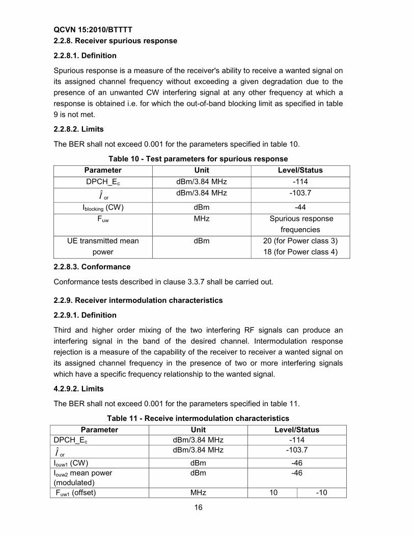
2.2.8. Receiver spurious response
2.2.8.1. Definition
Spurious response is a measure of the receiver's ability to receive a wanted signal on
its assigned channel frequency without exceeding a given degradation due to the
presence of an unwanted CW interfering signal at any other frequency at which a
response is obtained i.e. for which the out-of-band blocking limit as specified in table
9 is not met.
2.2.8.2. Limits
The BER shall not exceed 0.001 for the parameters specified in table 10.
Table 10 - Test parameters for spurious response
Parameter Unit Level/Status
DPCH_Ec dBm/3.84 MHz -114
I or dBm/3.84 MHz -103.7
Iblocking (CW) dBm -44
Fuw MHz Spurious response
frequencies
UE transmitted mean
power
dBm 20 (for Power class 3)
18 (for Power class 4)
2.2.8.3. Conformance
Conformance tests described in clause 3.3.7 shall be carried out.
2.2.9. Receiver intermodulation characteristics
2.2.9.1. Definition
Third and higher order mixing of the two interfering RF signals can produce an
interfering signal in the band of the desired channel. Intermodulation response
rejection is a measure of the capability of the receiver to receiver a wanted signal on
its assigned channel frequency in the presence of two or more interfering signals
which have a specific frequency relationship to the wanted signal.
4.2.9.2. Limits
The BER shall not exceed 0.001 for the parameters specified in table 11.
Table 11 - Receive intermodulation characteristics
Parameter Unit Level/Status DPCH_Ec dBm/3.84 MHz -114
I or dBm/3.84 MHz -103.7
Iouw1 (CW) dBm -46 Iouw2 mean power (modulated)
dBm -46
Fuw1 (offset) MHz 10 -10

QCVN 15:2010/BTTTT
17
Fuw2 (offset) MHz 20 -20 UE transmitted mean power
dBm 20 (for Power class 3) 18 (for Power class 4)
NOTE: Iouw2 (modulated) consists of the common channels and the 16 dedicated data channels as specified in TS 125 101.
2.2.9.3. Conformance
Conformance tests described in clause 3.3.8 shall be carried out.
2.2.10. Receiver spurious emissions
2.2.10.1. Definition
The spurious emissions power is the power of emissions generated or amplified in a
receiver that appear at the UE antenna connector.
2.2.10.2. Limits
The power of any narrow band CW spurious emission shall not exceed the maximum
level specified in tables 12 and 13.
Table 12 - General receiver spurious emission requirements
Frequency band Measurement bandwidth Maximum level
30 MHz ≤ f < 1 GHz 100 kHz -57 dBm
1 GHz ≤ f ≤ 12.75 GHz 1 MHz -47 dBm
Table 13 - Additional receiver spurious emission requirements
Frequency band Measurement
bandwidth
Maximum
level
Note
1920 MHz ≤ f ≤ 1980 MHz 3.84 MHz -60 dBm UE transmit band in
URA_PCH, Cell_PCH
and idle state
2110 MHz ≤ f ≤ 2170 MHz 3.84 MHz -60 dBm UE receive band
2.2.10.3 Conformance
Conformance tests described in clause 3.3.9 shall be carried out.
2.2.11. Out-of-synchronization handling of output power
2.2.11.1 Definition
The UE shall monitor the DPCCH quality in order to detect a loss of the signal on
Layer 1. The threshold Qout specifies at what DPCCH quality levels the UE shall shut
its power off. The threshold is not defined explicitly, but is defined by the conditions
under which the UE shall shut its transmitter off, as stated in this clause.
The DPCCH quality shall be monitored in the UE and compared to the threshold
Qout for the purpose of monitoring synchronization. The threshold Qout should
correspond to a level of DPCCH quality where no reliable detection of the TPC

QCVN 15:2010/BTTTT
18
commands transmitted on the downlink DPCCH can be made. This can be at a TPC
command error ratio level of e.g. 20%.
2.2.11.2. Limits
When the UE estimates the DPCCH quality over the last 160 ms period to be worse
than a threshold Qout the UE shall shut its transmitter off within 40 ms.
The quality level at the thresholds Qout correspond to different signal levels
depending on the downlink conditions DCH parameters. For the conditions in table
14, a signal with the quality at the level Qout can be generated by a DPCCH_Ec/Ior
ratio of -25 dB. The DL reference measurement channel (12.2 kbit/s) is specified in
annex D and with static propagation condition. The downlink physical channels, other
than those specified in table 14, are as specified in TS 134 121.
Table 14 - DCH parameters for test of out-of-synchronization handling
Parameter Value Unit
I or/Ioc -1 dB
Ioc -60 dBm/3.84 MHz
(DPDCH_Ec)/ Ior See figure 2:
Before point -16.6
After point A not defined
dB
(DPCCH_Ec)/ Ior See figure 2 dB
Information Data
Rate
12.2 kbit/s
Figure 2 shows an example scenario where the DPCCH_Ec/Ior ratio varies from a
level where the DPCH is demodulated under normal conditions, down to a level
below Qout where the UE shall shut its power off.

QCVN 15:2010/BTTTT
19
Figure 2 - Conditions for out-of-synch handling in the User Equipment
The requirements for the UE are that it shall shut its transmitter off before point C.
The UE transmitter is considered to be OFF if the measured RRC filtered mean
power is less than -55 dBm
2.2.11.3 Conformance
Conformance tests described in clause 3.3.10 shall be carried out.
2.2.12. Transmitter Adjacent Channel Leakage power Ratio
2.2.12.1 Definition
Adjacent Channel Leakage power Ratio (ACLR) is the ratio of the RRC filtered mean
power centred on the assigned channel frequency to the RRC filtered mean power
centred on an adjacent channel frequency.
2.2.12.2 Limits
Table 14a - UE ACLR
Power Class Adjacent channel frequency relative to
assigned channel frequency
ACLR limit
3 +5 MHz or -5 MHz 32.2 dB
3 +10 MHz or -10 MHz 42.2 dB
4 +5 MHz or -5 MHz 32.2 dB
4 +10 MHz or -10 MHz 42.2 dB Note: The requirement shall still be met in the presence of swithching transients.

QCVN 15:2010/BTTTT
20
2.2.12.3. Conformance
Conformance tests described in clause 3.3.11 shall be carried out.
2.2.13. Radiated emissions
2.2.13.1. Definition
This test assesses the ability of radio communications equipment and ancillary
equipment to limit unwanted emissions from the enclosure port.
This test is applicable to radio communications equipment and ancillary equipment.
This test shall be performed on the radio communications equipment and/or a
representative configuration of the ancillary equipment.
2.2.13.2. Limits
The frequency boundary and reference bandwidths for the detailed transitions of the
limits between the requirements for out of band emissions and spurious emissions
are based on ITU-R Recommendations SM.329-10 and SM.1539-1.
The requirements shown in table 15 are only applicable for frequencies in the
spurious domain.
Table 15 - Radiated spurious emissions requirements
Frequency Minimum requirement
(e.r.p)/reference
bandwidth idle mode
Minimum requirement
(e.r.p)/reference
bandwidth traffic
mode
Applicability
30 MHz ≤ f < 1000
MHz
-57 dBm/ 100 kHz -36 dBm/ 100 kHz All
1 GHz ≤ f < 12.75
GHz
-47 dBm/ 1 MHz -30 dBm/ 1 MHz All
NOTE: fc is the UE transmit centre frequency
2.2.13.3. Conformance
Conformance tests described in clause 3.3.12 shall be carried out.
2.2.14. Control and monitoring functions
2.2.14.1. Definition
This requirement, together with other control and monitoring technical requirements
identified in the table of cross references, verifies that the control and monitoring
functions of the UE prevent it from transmitting in the absence of a valid network.
This test is applicable to radio communications equipment and ancillary equipment.
This test shall be performed on the radio communications equipment and/or a
representative configuration of the ancillary equipment.

QCVN 15:2010/BTTTT
21
2.2.14.2. Limits
The maximum measured power during the duration of the test shall not exceed -30 dBm.
2.2.14.3 Conformance
Conformance tests described in clause 3.3.13 shall be carried out.
3. METHOD OF MEASUREMENT
3.1 Environmental conditions for testing
Tests defined in the present document shall be carried out at representative points
within the boundary limits of the declared operational environmental profile.
Where technical performance varies subject to environmental conditions, tests shall
be carried out under a sufficient variety of environmental conditions (within the
boundary limits of the declared operational environmental profile) to give confidence
of compliance for the affected technical requirements.
Normally it should be sufficient for all tests to be conducted using normal test
conditions except where otherwise stated. For guidance on the use of other
conditions to be used in order to show compliance reference can be made to TS 134
121.
Many tests in the present document are performed with appropriate frequencies in
the low, middle and high range of the operating frequency band of the UE. These
frequencies are defined in table E.1 of annex E.
3.2. Interpretation of the measurement results
The interpretation of the results recorded in a test report for the measurements
described in the present document shall be as follows:
- The measured value related to the corresponding limit will be used to decide
whether an equipment meets the requirements of the present document;
- The value of the measurement uncertainty for the measurement of each
parameter shall be included in the test report;
- The recorded value of the measurement uncertainty shall be, for each
measurement, equal to or lower than the figures in tables 16 and 16a.
For the test methods, according to the present document, the measurement
uncertainty figures shall be calculated in accordance with TR 100 028-1 and shall
correspond to an expansion factor (coverage factor) k = 1.96 (which provides a
confidence level of 95% in the case where the distributions characterizing the actual
measurement uncertainties are normal (Gaussian)). For guidance on other
measurement conditions reference can be made to annex (s) of TS 134 121.
Tables 16 and 16a are based on this expansion factor.

QCVN 15:2010/BTTTT
22
Table 16: Maximum measurement uncertainty of the test system
Parameter Conditions Test System
uncertainty
Transmitter maximum power ±0.7 dB
Transmitter spectrum
emissions mask ±1.5 dB
Transmitter spurious
emissions
f ≤ 2.2 GHz
2.2 GHz <f ≤ 4 GHz
f > 4 GHz
Co-existence band (> - 60
dBm):
Co-existence band (< - 60
dBm):
±1.5 dB
±2.0 dB
±4.0 dB
±2.0 dB
±3.0 dB
Transmitter Minimum output
power ±1.0 dB
Receiver Adjacent Channel
Selectivity (ACS) ±1.1 dB
Receiver Blocking
characteristics
f < 15 MHz offset:
15 MHz offset ≤ f ≤ 2.2 GHz
2.2 GHz < f ≤ 4 GHz
f > 4 GHz
±1.4 dB
±1.0 dB
±1.7 dB
±3.1 dB
Receiver spurious response
f ≤ 2.2 GHz
2.2 GHz < f ≤ 4 GHz
f > 4 GHz
±1.0 dB
±1.7 dB
±3.1 dB
Receiver intermodulation
characteristics ±1.3 dB
Receiver spurious emissions
For UE receive band (-60
dBm)
For UE transmit band (-60
dBm)
Outside the UE receive band:
f ≤ 2.2 GHz
2.2 GHz < f ≤ 4 GHz
f > 4 GHz
±3.0 dB
±3.0 dB
±2.0 dB
±2.0 dB
±4.0 dB
Out of synchronization of
handling power
DPCCH_Ec/Ior
Transmit OFF power
±0.4 dB
±1.0 dB
Transmitter adjacent channel
leakage power ratio ±0.8 dB

QCVN 15:2010/BTTTT
23
Table 16a - Maximum measurement uncertainty of radiated emissions, control
and monitoring functions
Parameter Uncertainty
Effective radiated RF power between 30 MHz and 180 MHz ±6 dB
Effective radiated RF power between 180 MHz and 12.75
GHz ±3 dB
Conducted RF power ±1 dB
NOTE 1: For RF tests it should be noted that the uncertainties in tables 16 and 16a apply to the test system
operating into a nominal 50Ω load and do not include system effects due to mismatch between the EUT and the
test system.
NOTE 2: Annex G of TR 100 028-2 [10] provides guidance for the calculation of the uncertainty components
relating to mismatch.
NOTE 3: If the test system for the test is known to have a measurement uncertainty greater than that specified in
tables 16 and 16a, this equipment can still be used provided that an adjustment is made follows: Any additional
uncertainty in the test system over and above that specified in tables 16 and 16a should be used to tighten the
test requirements-making the test harder to pass (for some tests, e.g. receiver tests, this may require modification
of stimulus signals).
3.3. Essential radio test suites
3.3.1. Transmitter maximum output power
3.3.1.1. Method of test
a) Initial conditions
Test environment: normal, TL/VL, TL/VH, TH/VL, TH/VH (for guidance see annex A).
The frequencies to be tested are low range, mid range and high range as defined in
table E1, annex E.
- Connect the SS to the UE antenna connector (as shown in figure C.1, annex C).
- A call is set up according to the Generic call setup procedure.
- Enter the UE into loopback test mode and start the loopback test.
NOTE: When reference is made to test set up, call set up and loopback test mode, guidance on the applicability
of these can be found in annex C, annex F and TS 134 109 respectively.
b) Procedure
- Set and send continuously Up power control commands to the UE.
- Measure the mean power of the UE in a bandwidth of at least (1+α) times the chip
rate of the radio access mode. The mean power shall be averaged over at least
one timeslot.
3.3.1.2. Test requirements
The results obtained shall be compared to the limits in clause 2.2.2.2 in order to show
compliance.

QCVN 15:2010/BTTTT
24
3.3.2 Transmitter spectrum emission mask
3.3.2.1. Method of test
a) Initial conditions
Test environment: normal (for guidance see annex A).
The frequencies to be tested are low range, mid range and high range as defined in
table E1, annex E.
- Connect the SS to the UE antenna connector (as shown in figure C.1, annex C).
- A call is set up according to the Generic call setup procedure.
- Enter the UE into loopback test mode and start the loopback test.
NOTE: When reference is made to test set up, call set up and loopback test mode, guidance on the applicability
of these can be found in annex C, annex F and TS 134 109 respectively.
b) Procedure
- Set and send continuously Up power control commands to the UE until the UE
output power shall be at the maximum level.
- Measure the power of the transmitted signal with a measurement filter of
bandwidths according to table 4. Measurements with an offset from the carrier
centre frequency between 2.515 MHz and 3.485 MHz shall use a 30 kHz
measurement filter. Measurements with an offset from the carrier centre
frequency between 4 MHz and 12 MHz shall use 1 MHz measurement bandwidth
and the result may be calculated by integrating multiple 50 kHz or narrower filter
measurements. The characteristic of the filter shall be approximately Gaussian
(typical spectrum analyzer filter). The centre frequency of the filter shall be
stepped in contiguous steps according to table 4. The measured power shall be
recorded for each step.
- Measure the RRC filtered mean power centred on the assigned channel
frequency.
- Calculate the ratio of the power 2) with respect to 3) in dBc.
3.3.2.2. Test requirements
The results obtained shall be compared to the limits in clause 2.2.3.2 in order to show
compliance.
3.3.3. Transmitter spurious emissions
3.3.3.1. Method of test
a) Initial conditions
Test environment: normal (for guidance see annex A).

QCVN 15:2010/BTTTT
25
The frequencies to be tested are low range, mid range and high range as
defined in table E1, annex E.
- Connect the SS to the UE antenna connector (as shown in figure C.6, annex C).
- A call is set up according to the Generic call setup procedure.
- Enter the UE into loopback test mode and start the loopback test.
NOTE: When reference is made to test set up, call set up and loopback test mode, guidance on the applicability
of these can be found in annex C, annex F and TS 134 109 respectively.
b) Procedure
- Set and send continuously Up power control commands to the UE until the UE
output power shall be maximum level.
- Sweep the spectrum analyser (or equivalent equipment) over a frequency range
and measure the average power of spurious emission.
3.3.3.2 Test requirements
The results obtained shall be compared to the limits in clause 2.2.4.2 in order to show
compliance.
3.3.4. Transmitter minimum output power
3.3.4.1. Method of test
a) Initial conditions
Test environment: normal, TL/VL, TL/VH, TH/VL, TH/VH (for guidance see annex A).
The frequencies to be tested are mid range as defined in table E1, annex E.
- Connect the SS to the UE antenna connector (as shown in figure C.1, annex C).
- A call is set up according to the Generic call setup procedure.
- Enter the UE into loopback test mode and start the loopback test.
NOTE: When reference is made to test set up, call set up and loopback test mode, guidance on the applicability
of these can be found in annex C, annex F and TS 134 109 respectively.
b) Procedure
- Set and send continuously Down power control commands to the UE.
- Measure the mean power of the UE.
3.3.4.2. Test requirements
The results obtained shall be compared to the limits in clause 4.2.5.2 in order to show
compliance.

QCVN 15:2010/BTTTT
26
3.3.5. Receiver adjacent channel selectivity (ACS)
3.3.5.1 Method of test
a) Initial conditions
Test environment: normal (for guidance see annex A).
The frequencies to be tested are mid range as defined in table E1, annex E.
- Connect the SS to the UE antenna connector (as shown in figure C.2, annex C).
- A call is set up according to the Generic call setup procedure, and RF parameters
are set up according to table 7.
- Enter the UE into loopback test mode and start the loopback test.
NOTE: When reference is made to test set up, call set up and loopback test mode, guidance on the applicability
of these can be found in annex C, annex F and TS 134 109 respectively.
b) Procedure
- Set the parameters of the interference signal generator as shown in table 7.
- Set the power level of the UE according to table 7 with a ±1 dB tolerance.
- Measure the BER of DCH received from the UE at the SS.
3.3.5.2 Test requirements
The results obtained shall be compared to the limits in clause 2.2.6.2 in order to show
compliance.
3.3.6. Receiver blocking characteristics
3.3.6.1 Method of test
a) Initial requirements
Test environment: normal (for guidance see annex A).
For in band case, the frequencies to be tested are mid range as defined in table E1,
annex E.
For out-of-band case, frequencies to be, mid range as defined in table E1, annex E.
- Connect the SS to the UE antenna connector (as shown in figure C.3, annex C).
- A call is set up according to the Generic call setup procedure, and RF parameters
are set up according to tables 8 and 9.
- Enter the UE into loopback test mode and start the loopback test.
NOTE: When reference is made to test set up, call set up and loopback test mode, guidance on the applicability
of these can be found in annex C, annex F and TS 134 109 respectively.
b) Procedure

QCVN 15:2010/BTTTT
27
- Set the parameters of the CW generator or the interference signal generator as
shown in tables 8 and 9. For table 9 the frequency step size is 1 MHz.
- Set the power level of the UE according to tables 8 and 9 with a ±1 dB tolerance.
- Measure the BER of DCH received from the UE at the SS.
- For table 9, record the frequencies for which the BER exceeds the test
requirements.
3.3.6.2 Test requirements
The results obtained shall be compared to the limits in clause 2.2.7.2 in order to show
compliance.
3.3.7. Receiver spurious response
3.3.7.1. Method of test
a) Initial conditions
Test environment: normal (for guidance see annex A).
The frequencies to be tested are mid range as defined in table E1, annex E.
- Connect the SS to the UE antenna connector (as shown in figure C.4, annex C).
- A call is set up according to the Generic call setup procedure, and RF parameters
are set up according to table 10.
- Enter the UE into loopback test mode and start the loopback test.
NOTE: When reference is made to test set up, call set up and loopback test mode, guidance on the applicability
of these can be found in annex C, annex F and TS 134 109 respectively.
b) Procedure
- Set the parameter of the CW generator as shown in table 10. The spurious
response frequencies are determined in step 4) of clause 5.3.6.1.2.
- Set the power level of the UE according to table 10 with a ±1 dB tolerance.
- Measure the BER of DCH received from the UE at the SS.
3.3.7.2 Test requirements
The results obtained shall be compared to the limits in clause 2.2.8.2. in order to
show compliance.
3.3.8 Receiver Intermodulation characteristics
3.3.8.1. Method of test
a) Initial conditions
Test environment: normal (for guidance see annex A).
The frequencies to be tested are mid range as defined in table E1, annex E.

QCVN 15:2010/BTTTT
28
- Connect the SS to the UE antenna connector (as shown in figure C.5, annex C).
- A call is set up according to the Generic call setup procedure as per annex F, and
RF parameters are set up according to table 11.
- Enter the UE into loopback test mode and start the loopback test using the
procedure defined in TS 134 109 [8].
NOTE: When reference is made to test set up, call set up and loopback test mode, guidance on the applicability
of these can be found in annex C, annex F and TS 134 109 respectively.
b) Procedure
- Set the parameters of the CW generator and interference generator as shown in
table 11.
- Set the power level of the UE according to table 11 with a ±1 dB tolerance.
- Measure the BER of DCH received from the UE at the SS.
3.3.8.2. Test requirements
The results obtained shall be compared to the limits in clause 4.2.9.2 in order to show
compliance.
3.3.9. Receiver spurious emissions
3.3.9.1. Method of test
a) Initial conditions
Test environment: normal (for guidance see annex A).
The frequencies to be tested are mid range as defined in table E1, annex E.
- Connect a spectrum analyser (or other suitable test equipment) to the UE antenna
connector (as shown in figure C.6, annex C).
- UE shall be in CELL_FACH state.
- The UE shall be setup such that UE will not transmit during the measurement.
(For guidance see TS 134 121.)
b) Procedure
Sweep the spectrum analyser (or other suitable test equipment) over a frequency
range from 30 MHz to 12.75 GHz and measure the average power of the spurious
emissions.
3.3.9.2. Test requirements
The results obtained shall be compared to the limits in clause 2.2.10.2 in order to
show compliance.
3.3.10. Out-of-synchronization handling of output power

QCVN 15:2010/BTTTT
29
3.3.10.1. Method of test
a) Initial conditions
Test environment: normal (for guidance see annex A).
The frequencies to be tested are mid range as defined in table E1, annex E.
- Connect the SS to the UE antenna connector (as shown in figure C.1, annex C).
- A call is set up according to the Generic call setup procedure, with the following
exception according to table 17 for information elements in System Information
Block type 1 found in TS 134.108.
Table 17 - System Information Block type 1 message
Information Element Value/Remark
UE Timers and constants in connected mode
-T313 15 s
-N313 200
- RF parameters are set up according to table 14 with DPCCH_Ec/Ior ratio level at -
16.6 dB.
- Enter the UE into loopback test mode and start the loopback test.
NOTE: When reference is made to test set up, call set up and loopback test mode, guidance on the applicability
of these can be found in annex C, annex F and TS 134 109 respectively.
b) Procedure
- The SS sends continuously up power control commands to the UE until the UE
transmitter power reach maximum level.
- The SS controls the DPCCH_Ec/Ior ratio level to -21.6 dB.
- The SS controls the DPCCH_Ec/Ior ratio level to -28.4 dB. The SS waits 200 ms
and then verifies that the UE transmitter has been switched off.
- The SS monitors the UE transmitted power for 5 s and verifies that the UE
transmitter is not switched on during this time.
3.3.10.2. Test requirements
The results obtained shall be compared to the limits in clause 2.2.11.2 in order to
compliance.
3.3.11. Transmitter adjacent channel leakage power ratio
3.3.11.1. Method of test
a) Initial conditions
Test environment: normal, TL/VL, TL/VH, TH/VL, TH/VH (for guidance see annex A).
The frequencies to be tested are mid range as defined in table E1, annex E.

QCVN 15:2010/BTTTT
30
- Connect the SS to the UE antenna connector (as shown in figure C.1, annex C).
- A call is set up according to the Generic call setup procedure.
- Enter the UE into loopback test mode and start the loopback test.
NOTE: When reference is made to test set up, call set up and loopback test mode, guidance on the applicability
of these can be found in annex C, annex F and TS 134 109 respectively.
b) Procedure
- The SS sends continuously Up power control commands to the UE until the UE
transmitter power reach maximum level.
- Measure the RRC filtered mean power.
- Measure the RRC filtered mean power of the first adjacent channels and the
second adjacent channels.
- Calculate the ratio of the power between the values measured in 2) and 3) above.
3.3.11.2 Test requirements
The results obtained shall be compared to the limits in clause 2.2.12.2 in order to
compliance.
3.3.12. Radiated emissions
3.3.12.1. Method of test
Whenever possible the test site should be a fully anechoic chamber simulating the
free-space conditions. EUT shall be placed on a non-conducting support. Average
power of any spurious components shall be detected by the test antenna and
measuring receiver (e.g. a spectrum analyser).
At each frequency at which a component is detected, the EUT shall be rotated to
obtain maximum response, and the effective radiated power (e.r.p) of that component
determined by a substitution measurement, which shall be the reference method. The
measurement shall be repeated with the test antenna in the orthogonal polarization
plane.
NOTE: Effective radiated power (e.r.p) refers to the radiation of a half wave tuned dipole instead of an isotropic
antenna. There is a constant difference of 2.15 dB between e.i.r.p. and e.r.p.
e.r.p. (dBm) = e.i.r.p. (dBm) - 2.15
(ITU-R Recommendation SM.329-10, annex 1).
Measurements are made with a tuned dipole antenna or a reference antenna with a
known gain referenced to an isotropic antenna.
If a different test site or method is used, this shall be stated in the test report. The
results shall be converted to the reference method values and the validity of the
conversion shall be demonstrated.
3.3.12.2 Test configurations

QCVN 15:2010/BTTTT
31
This clause defines the configurations for emission tests as follows:
- The equipment shall be tested under normal test conditions;
- The test configuration shall be as close to normal intended use as possible;
- If the equipment is part of a system, or can be connected to ancillary equipment,
then it shall be acceptable to test the equipment while connected to the minimum
configuration of ancillary equipment necessary to exercise the ports;
- If the equipment has a large number of ports, then a sufficient number shall be
selected to simulate actual operation conditions and to ensure that all the different
types of termination are tested;
- The test conditions, test configuration and mode of operation shall be recorded in
the test report;
- Ports which in normal operation are connected shall be connected to an ancillary
equipment or to a representative piece of cable correctly terminated to simulate
the input/output characteristics of the ancillary equipment, RF input/output ports
shall be correctly terminated;
- Ports that are not connected to cables during normal operation, e.g. service
connectors, programming connectors; temporary connectors etc. shall not be
connected to any cables for the purpose of this test. Where cables have to be
connected to these ports, or interconnecting cables have to be extended in length
in order to exercise the EUT, precautions shall be taken to ensure that the
evaluation of the EUT is not affected by the addition or extension of these cables;
Emission tests shall be performed in two modes of operation:
- With a communication link established (traffic mode); and
- In the idle mode.
The results obtained shall be compared to the limits in clause 2.2.13.2 in order to
prove compliance.
3.3.13 Control and monitoring functions
3.3.13.1 Method of test
1) At the start of the test, the UE shall be switched off. The UE antenna connector
shall be connected to a power measuring equipment, with the following
characteristics:
- The RF bandwidth shall exceed the total operating transmit frequency range of
the UE;
- The response time of the power measuring equipment shall be such that the
measured power has reached within 1 dB of its steady state value within 100 µs
of a CW signal being applied;

QCVN 15:2010/BTTTT
32
- It shall record the maximum power measured.
NOTE: The equipment may include a video low pass filter to minimize its response to transients or Gaussian
noise peaks.
2) The UE shall be switched on for a period of approximately fifteen minutes, and
then switched off.
3) The EUT shall remain switched off for a period of at least thirty seconds, and shall
then be switched on for a period of approximately one minute.
4) Step 2) shall be repeated four times.
5) The maximum power emitted from the UE throughout the duration of the test shall
be recorded.
The results obtained shall be compared to the limits in clause 2.2.14.2 in order to
prove compliance.
4. MANAGEMENT REGULATIONS
User Equipments for use in the IMT-2000 CDMA Direct Spread (UTRA FDD) must
comply with requirements in this technical regulation.
5. RESPONSIBILITY OF ORGANISATIONS/INDIVIDUALS
Organisations/individuals in Vietnam are responsible to comply with this technical
regulation and to accept supervision of regulatory authority as existing regulations.
6. IMPLEMENTATION
5.1. Vietnam Telecommunication Authority and local departments of Information and
Communications are responsible for guidance and implementation of this technical
regulation.
5.2. This Technical Regulation replace standard TCN 68-245:2006 “Mobile Stations
for IMT-2000 CDMA Direct Spread (W-CDMA FDD) - Technical Requirements”.
5.3. In cases of having referencing regulations specified in this technical regulation
changed, modified or superseded, the new reference versions are applied.

QCVN 15:2010/BTTTT
33
Annex A
(Informative)
Environmental profile
A.1. Temperature
The UE should fulfil all the requirements in the full temperature range as given in
table A.1.
Table A.1 - Temperatures
Range Conditions
+15oC to +35oC For normal conditions (with relative humidity of 25%
to 75%)
-10oC to +55oC For extreme conditions (see IEC publications 60068-
2-1 [12] and 60068-2-2 [13])
Outside this temperature range the UE, if powered on, shall not make ineffective use
of the radio frequency spectrum. In no case shall the UE exceed the transmitted
levels as defined in TS 125.101 [5] for extreme operation.
These test conditions are denoted as TL (temperature low, -100C) and TH
(temperature high, +550C).
A.2. Voltage
The UE shall fulfil all the requirements in the full voltage range, i.e. the voltage range
between the extreme voltages.
The manufacturer shall declare the lower and higher extreme voltages and the
approximate shutdown voltage. For the equipment that can be operated from one or
more of the power sources listed in table A.2, the lower extreme voltage shall not be
higher, and the higher extreme voltage shall not be lower than that specified in table
A.2.
Table A.2 - Power sources
Outside this voltage range the UE if powered on, shall not make ineffective use of the
radio frequency spectrum. In no case shall the UE exceed the transmitted levels as
defined in TS 125.101 [5] for extreme operation. In particular, the UE shall inhibit all

QCVN 15:2010/BTTTT
34
RF transmissions when the power supply voltage is below the manufacturer declared
shutdown voltage.
These test conditions are denoted as VL (lower extreme voltage) and VH (higher
extreme voltage).
A.3. Test environment
Where a normal environment is required then the normal conditions shown in clauses
A.1 and A.2 should be applied.
Where an extreme environment is required then the various combinations of extreme
temperatures together with the extreme voltages shown in clauses A.1 and A.2
should be applied. The combinations are:
• Low extreme temperature/low extreme voltage (TL/VL);
• Low extreme temperature/high extreme voltage (TL/VH);
• High extreme temperature/low extreme voltage (TH/VL);
• High extreme temperature/high extreme voltage (TH/VH).
A.4. Vibration
The UE shall fulfil all the requirements when vibrated at the following
frequency/amplitudes:
Table A.3 - Vibration
Frequency ASD (Acceleration Spectral Density) random
vibration
5 Hz to 20 Hz 0.96 m2/s3
20 Hz to 500 Hz 0.96 m2/s3 at 20 Hz, thereafter - 3 dB/Octave
Outside the specified frequency range the UE, if powered on, shall not make
ineffective use of the radio frequency spectrum. In no case shall the UE exceed the
transmitted levels as defined in TS 125.101 [5] for extreme operation.
A.5. Specified frequency range
The manufacturer shall declare, which of the frequency bands defined in clause 4.2,
TS 134 121 is supported by the UE.
Some tests in the present document are performed also in low, mid and high range of
the operating frequency band of the UE. The UARFCN's to be used for low, mid and
high range are defined in table E1, annex E.
A.6. Acceptable uncertainty of Test System
The maximum acceptable uncertainty of the Test System is specified in tables 16 and
16a for each test, where appropriate. The Test System shall enable the stimulus
signals in the test case to be adjusted to within the specified range, and the

QCVN 15:2010/BTTTT
35
equipment under test to be measured with an uncertainty not exceeding the specified
values. All ranges and uncertainties are absolute values, and are valid for a
confidence level of 95 %, unless otherwise stated.
A confidence level of 95% is the measurement uncertainty tolerance interval for a
specific measurement that contains 95% of the performance of a population of test
equipment.
For RF tests it should be noted that the uncertainties in clause A.6 apply to the Test
System operating into a nominal 50 ohm load and do not include system effects due
to mismatch between the EUT and the Test System.
A.6.1. Measurement of test environments
The measurement accuracy of the UE test environments defined in clauses A.1, A.2,
A.4 and A.5 shall be:
- Pressure : ±5 kPa.
- Temperature : ±2 degrees.
- Relative Humidity : ±5 %.
- DC Voltage : ±1.0 %.
- AC Voltage : ±1.5 %.
- Vibration : 10 %.
- Vibration frequency : 0.1 Hz.
The above values shall apply unless the test environment is otherwise controlled and
the specification for the control of the test environment specifies the uncertainty for
the parameter.

QCVN 15:2010/BTTTT
36
Annex B
(Informative)
Receiver sensitivity and correct operation of the equipment
B.1 Receiver sensitivity
In the cellular radio communications systems using IMT-2000 standards within the
scope of the present document, the power of transmissions is usually controlled so
that the power of the transmitted signal intended to be received by a particular
receiver is reduced to the minimum level consistent with proper reception. This is
accomplished by a closed-loop employing messages reporting received power and/or
signal quality between the BS and UE.
If a receiver has inadequate receiver sensitivity, the power of the transmitted signal
intended for that receiver will need to be much higher than would otherwise be
needed. If the transmitted power is increased excessively, this will cause harmful
interference to other receivers using the same frequency in the neighbouring
geographic area. Therefore, receiver sensitivity is justified as an essential
requirement [1].
The product specifications for IMT-2000 UE and BS (falling within the scope of
applicable parts) include requirements relating to receiver sensitivity. The level of
these requirements has been based on consideration of the performance of that
receiver, and not harmful interference indirectly caused to other receivers. As a
consequence, these requirements are too stringent to be justified as essential
requirements [1]. However, the applicable parts [1] for IMT-2000 UE and BS include
an essential requirement for strong interfering signal handling of the receiver. This
requirement implicitly requires a certain level of receiver performance, which is less
stringent than that required by the product requirements relating directly to receiver
sensitivity.
It is considered that the level of receiver performance needed by an IMT-2000 UE
and BS to meet the essential requirement for receiver strong interfering signal
handling is an appropriate level for an essential requirement [1].
Therefore, no separate conformance requirement is defined in the present document
or in the applicable parts relating to receiver sensitivity.
B.2 Correct functioning of the equipment
In a radio communications system, it is essential that certain functions of equipment
operate correctly, in order to prevent harmful interference to other users of the radio
spectrum. These functions can include transmission on the correct frequency, at the
correct time and/or using the correct code (for equipment using CDMA). For the BS,
the parameters of these functions are commanded by the network, and for the UE
they are commanded by the BS.

QCVN 15:2010/BTTTT
37
Several of the tests in the applicable parts implicitly require a connection to be
established between the Equipment Under Test (EUT) and the test apparatus. This
implicitly requires the EUT to respond correctly to the commands it receives.
It is considered that the establishment of a connection demonstrates that the
equipment meets most aspects of correct functioning to meet the essential
requirements [1]. Tests for certain specific functions are defined in applicable parts,
where these functions are critical to the prevention of harmful interference.
Therefore, the explicit tests for correct functioning of the equipment, together with the
implicit testing through the ability to establish a connection, are sufficient to meet the
essential requirement for correct functioning of the equipment so as to prevent
harmful interference.

QCVN 15:2010/BTTTT
38
Annex C
(Informative)
Test Models
System Simulator or SS – A device or system, that is capable of generating
simulated Node B signalling and analysing UE signalling responses on one or more
RF channels, in order to create the required test environment for the UE under test. It
will also include the following capabilities:
1. Measurement and control of the UE Tx output power through TPC commands
2. Measurement of RX BLER and BER
3. Measurement of signalling timing and delays
4. Ability to simulate UTRAN and/or GERAN signalling
Test System – A combination of devices brought together into a system for the
purpose of making one or more measurements on a UE in accordance with the test
case requirements. A test system may include one or more System Simulators if
additional signalling is required for the test case. The following diagrams are all
examples of Test Systems.
NOTE: The above terms are logical definitions to be used to describe the test methods used in this document, in
practice, real devices called 'System Simulators' may also include additional measurement capabilities or may
only support those features required for the test cases they are designed to perform.
Figure C.1 - Connection for Basic TX Test

QCVN 15:2010/BTTTT
39
Figure C.2 - Connection for RX Test with Interference
Figure C.3 - Connection for RX Test with Interference or additional CW
Figure C.4 - Connection for RX Test with additional CW

QCVN 15:2010/BTTTT
40
Figure C.5 - Connection for RX Test with both Interference and additional CW
Figure C.6 - Connection for Spurious Emission Test

QCVN 15:2010/BTTTT
41
Annex D
(Normative)
DL reference measurement channel (12.2 kbps) and static propagation
condition
D.1. DL reference measurement channel (12.2 kbps)
The parameters for the 12.2 kbps DL reference measurement channel are specified
in table D.1.1, table D.1.2, table D.1.3. The channel coding is detailed in figure D.1.1.
For the RLC configuration of AM DCCHs Timer_STATUS_Periodic shall not be set in
RRC CONNECTION SETUP message used in test procedure for RF test as defined
in TS 34.108 clause 7.3. This is to prevent unexpected DCHs from being transmitted
through such RLC entities when the timer has expired in order to sure that the
required TFC from the minimum set of TFCs can continuously convey a DCH for
DTCH during the test.
Table D.1.1 - DL reference measurement channel (12.2 kbps)
Parameter Level Unit
Information bit rate 12.2 kbps
DPCH 30 ksps
Slot format #1 11 -
TFCI On
Power offsets PO1, PO2 and PO3 0 dB
DTX position Fixed -

QCVN 15:2010/BTTTT
42
Table D.1.2 - DL reference measurement channel using RLC-TM for DTCH,
transport channel parameters (12.2 kbps)
Higher Layer RAB/Signalling RB RAB SRB
RLC Logical channel type DTCH DCCH
RLC mode TM UM/AM
Payload sizes, bit 244 88/80
Max data rate, bps 12200 2200/2000
PDU header, bit N/A 8/16
TrD PDU header, bit 0 N/A
MAC MAC header, bit 0 4
MAC multiplexing N/A Yes
Layer 1 TrCH type DCH DCH
Transport Channel Identity 6 10
TB sizes, bit 244 100
TFS TF0, bits 0x244 0x100
TF1, bits 1x244 1x100
TTI, ms 20 40
Coding type Convolution
coding
Convolution
coding
Coding rate 1/3 1/3
CRC, bit 16 12
Max number of bits/TTI after
channel coding
804 360
RM attribute 256 256
Table D.1.3 - DL reference measurement channel, TFCS (12.2 kbps)
TFCS size 4
TFCS (DTCH, DCCH) = (TF0, TF0), (TF1, TF0), (TF0, TF1), (TF1,
TF1)

QCVN 15:2010/BTTTT
43
Figure D.1.1- Channel coding of DL reference measurement channel (12.2 kbps)
D.2. Static propagation condition
The propagation for the static performance measurement is an Additive White
Gaussian Noise (AWGN) environment. No fading and multi-paths exist for this
propagation model.

QCVN 15:2010/BTTTT
44
Annex E
(Normative)
UE Conformance Test Frequencies
The test frequencies are based the UMTS frequency bands defined in the core
specifications.
To avoid interference with adjacent frequency bands the lowest test frequency
(downlink and uplink) needs to be offset upwardly by at least 2.6 MHz since the
channel's width is 5 MHz for FDD option. The raster spacing is 200 kHz. Similarly the
highest test frequency (downlink and uplink) needs to be offset downwardly by at
least 2.6 MHz for FDD option.
NOTE: Additional regulations concerning interferences to frequency bands used by different systems may also
exist. Those regulations are specific to the country where the test equipment is used and need to be taken into
account if they require a higher offset than 2.6 MHz from the edge frequencies for FDD option.
UE Conformance Test Frequencies (UTRA/FDD)
UTRA/FDD is designed to operate in one of three paired bands [5]. The reference
test frequencies for the common test environment for CDMA Direct Spread service
(UTRA FDD) are defined in the following table:
Table E.1- FDD reference test frequencies for CDMA Direct Spread service
(UTRA FDD)
Test Frequency
ID
UARFC
N
Frequency of
Uplink
UARFC
N
Frequency of
Downlink
Low range 9613 1922.6 MHz 10563 2112.6 MHz
Mid range 9750 1950.0 MHz 10700 2140.0 MHz
High range 9887 1977.4 MHz 10837 2167.4 MHz

QCVN 15:2010/BTTTT
45
Annex F
(Informative)
Generic Call Setup Procedure
F.1. Generic call set-up procedure for mobile terminating circuit switched calls
F.1.1. Initial conditions
System Simulator:
- 1 cell, default parameters.
User Equipment:
- The UE shall be operated under normal test conditions.
- The Test-USIM shall be inserted.
F.1.2. Definition of system information messages
The default system information messages are used.
F.1.3. Procedure
The Call Set-up procedure shall be performed under Ideal radio conditions as defined
in TS 134 108, clause 5.
Step Direction Message Comments UE SS 1 ← SYSTEM INFORMATION (BCCH) Broadcast 2 ← PAGING (PCCH) Paging 3 → RRC CONNECTION REQUEST
(CCCH) RRC
4 ← RRC CONNECTION SETUP (CCCH) RRC 5 → RRC CONNECTION SETUP
COMPLETE (DCCH) RRC
6 → PAGING RESPONSE RR 7 ← AUTHENTICATION REQUEST MM 8 → AUTHENTICATION RESPONSE MM 9 ← SECURITY MODE COMMAND RRC
10 → SECURITY MODE COMPLETE RRC 11 ← SETUP CC 12 → CALL CONFIRMED CC 13 ← RADIO BEARER SETUP RRC RAB SETUP 14 → RADIO BEARER SETUP COMPLETE RRC 15 → ALERTING CC (this msg is
optional) 16 → CONNECT CC 17 ← CONNECT ACKNOWLEDGE CC
F.1.4. Specific message contents
All Specific message contents shall be referred to TS 134 108 [7],clause 9.

QCVN 15:2010/BTTTT
46
F.2. Generic call set-up procedure for mobile originating circuit switched calls
F.2.1. Initial conditions
System Simulator:
- 1 cell, default parameters.
User Equipment:
- The UE shall be operated under normal test conditions.
- The Test-USIM shall be inserted.
F.2.2. Definition of system information messages
The default system information messages are used.
F.2.3. Procedure
The Call Set-up procedure shall be performed under Ideal radio conditions as defined
in TS 134 108, clause 5.
Step Direction Message Comments UE SS
1 ← SYSTEM INFORMATION (BCCH) Broadcast 2 → RRC CONNECTION REQUEST
(CCCH) RRC
3 ← RRC CONNECTION SETUP (CCCH)
RRC
4 → RRC CONNECTION SETUP COMPLETE (DCCH)
RRC
5 → CM SERVICE REQUEST MM 6 ← AUTHENTICATION REQUEST MM 7 → AUTHENTICATION RESPONSE MM 8 ← SECURITY MODE COMMAND RRC 9 → SECURITY MODE COMPLETE RRC 10 → SETUP CC 11 ← CALL PROCEEDING CC 12 ← RADIO BEARER SETUP RRC RAB SETUP 13 → RADIO BEARER SETUP
COMPLETE RRC
14 ← ALERTING CC 15 ← CONNECT CC 16 → CONNECT ACKNOWLEDGE CC
F.2.4. Specific message contents
All Specific message contents shall be referred to TS 134 108, clause 9.

QCVN 15:2010/BTTTT
47
Annex G
(Normative)
W-CDMA Modulated Interferer
The W-CDMA modulated interferer consists of the downlink channels defined in table
G.1 plus the OCNS channels defined in Table G.2. The relative power of the OCNS
channels shall be such that the power of the total signal adds up to one. In this
subclause Ior refers to the power of the interferer.
Table G.1 - Spreading Code, Timing offsets and relative level settings for W-
CDMA Modulated Interferer signal channels
Channel
Type
Spreading
Factor
Channelization
Code
Timing
Offset
(x 256
Tchip)
Power Note
P-
CCPCH
256 1 0 P-
CCPCH_Ec/Ior
= - 10 dB
SCH 256 - 0 SCH_Ec/Ior = -
10 dB
The SCH
power shall
be divided
equally
between
Primary and
Secondary
Synchronous
channels
P-CPICH 256 0 0 P-CPICH_Ec/Ior
= - 10 dB
PICH 256 16 16 PICH_Ec/Ior = -
15 dB
OCNS See table G.2 Necessary
power so that
total transmit
power spectral
density of Node
B (Ior) adds to
one
OCNS
interference
consists of
the dedicated
data
channels. as
specified in
Table G.2

QCVN 15:2010/BTTTT
48
Table G.2- DPCH Channelization Code and relative level settings for OCNS signal
Channelization
Code SF=128
Relative Level
Settings (dB)
(Note 2)
DPCH Data
2 -1 The DPCH data for each
channelization code shall be
uncorrelated with each other and with
any wanted signal over the period of
any measurement.
11 -3
17 -3
23 -5
31 -2
38 -4
47 -8
55 -7
62 -4
69 -6
78 -5
85 -9
94 -10
125 -8
113 -6
119 0
NOTE 1: The DPCH Channelization Codes and relative level settings are chosen to simulate a signal with realistic
Peak to Average Ratio.
NOTE 2: The relative level setting specified in dB refers only to the relationship between the OCNS channels. The
level of the OCNS channels relative to the Ior of the complete signal is a function of the power of the other
channels in the signal with the intention that the power of the group of OCNS channels is used to make the total
signal add up to 1.