pv water pumping system using a current-fed … water pumping...pv water pumping system using a...
TRANSCRIPT
Asian J. Energy Environ., Vol. 5, Issue 3, (2004), pp. 171-196
Copyright © 2004 by the Joint Graduate School of Energy and Environment 171
PV Water Pumping System Using a
Current-Fed Parallel Resonant
Push-Pull Inverter for Rural Area
Applications
D. C. Martins*, M. Mezaroba, O. H. Gonçalves
and A. S. de Andrade
Federal University of Santa Catarina
Power Electronics Institute - INEP
P.O. BOX 5119 - 88.040-970 - Florianópolis - SC - Brazil
*Corresponding author: Tel.: 55(48)231-9204; Fax: 55(48)234-5422
E-mail: [email protected]
(Received : 31 January 2004 – Accepted : 15 March 2004)
Abstract: This paper presents the analysis of a water pumping
system from photovoltaic cells using a current-fed parallel
resonant push-pull inverter, for residential applications in rural
areas. The structure of the power circuit is particularly simple
and robust. It works in a ZVS commutation. Its main features
are: one power processing stage, simple control strategy, low
harmonic distortion of the load voltage, and natural isolation.
The principle of operation, design procedure and experimental
results are presented.

D. C. Martins, M. Mezaroba, O. H. Gonçalves and A. S. de Andrade
172 Asian J. Energy Environ., Vol. 5, Issue 3, (2004), pp. 171-196
Keywords: PV Water Pumping System, Resonant Converter,
Push-Pull Inverter, PWM Modulation, PV Solar
Cells.
Introduction
The increasing research to discover alternative means for
obtaining electrical energy in a simple manner, without
pollution, that at the same time do not cause a hard ecological
impact on the environment, has led some professionals of the
electrical engineering area to opt for solar energy conversion.
This kind of energy, apparently unfailing, presents a series
of advantages, among them we can point out: non-aggression to
natural conditions, and no cause of any type of pollution.
However, its treatment for industrial applications and even for
residential ones still represents a relatively high cost. Nowadays
studies in the conception and materials manufacture area for
photovoltaic cells are rapidly being developed with great
success. The main objective is to obtain systems for converting
solar energy into electrical energy in a simple, cheap and safe
way.
Considering the objective mentioned above, this paper
describes a system for residential applications in rural areas,
where power from a utility is not available or is too costly to
install. The system consists of water pumping from photovoltaic
cells using a current-fed parallel resonant push-pull inverter with
battery storage.

PV Water Pump. Sys. Using a Cur.-Fed Parallel Res. Push-Pull Inv. for Rural Area App.
Asian J. Energy Environ., Vol. 5, Issue 3, (2004), pp. 171-196 173
Much work in the PV water pumping area for residential
applications, is available in technical literature. The majority of
them use an AC or DC machine to drive the water pump
[1,2,3,4]. The main inconvenience presented by these systems
are: low efficiency, high reactive power circulation, expensive
maintenance, complex electronic drive circuits, large volume,
and high weight and cost. These items are particularly serious in
rural applications, in which maintenance, simplicity and cost
must be optimized.
The system proposed in this work uses a vibratory under-
water pump that consists of an electromagnet circuit, which
produces a vibration in a diaphragm with the same operation
frequency of the electromagnet circuit.
The studies realized during this work show that the
current-fed parallel resonant push-pull inverter is very well
adapted to this kind of load (vibratory under-water pump) [8]. It
naturally generates a high quality sinusoidal voltage waveform
across the pump, with ZVS commutation. This strategy permits
simple and safe operation of the whole system.
The main advantages of the proposal mentioned above are:
absence of any rotating mechanical part, that diminishes the
wear and tear of pump pieces and augments the efficiency of the
system, robustness, low maintenance, simplicity of the control
drive circuit, easy installation and operation, low weight,
volume and cost.
D. C. Martins, M. Mezaroba, O. H. Gonçalves and A. S. de Andrade
174 Asian J. Energy Environ., Vol. 5, Issue 3, (2004), pp. 171-196
Equivalent Electric Model of the Vibratory
Under-Water Pump
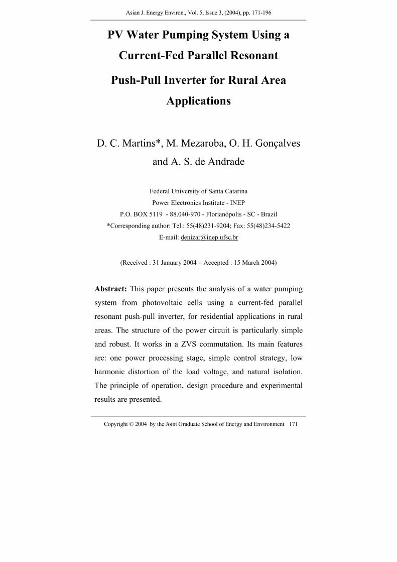
For rural area application the vibratory under-water pump
is particularly recommended due its simplicity, low cost and
robustness. Besides, this pump can effect the pumping in well
with profundity around 80 metres. Under normal conditions the
pumping is approximately 1500 litres per hour. In Figure 1 we
can observe the behavior of the pump for various profundities.
0
500
1000
1500
2000
0 10 20 30 40 50 60 70 80height (meters)
flow
of w
ater
(lite
rs)
Figure 1. Performance of the water pump.
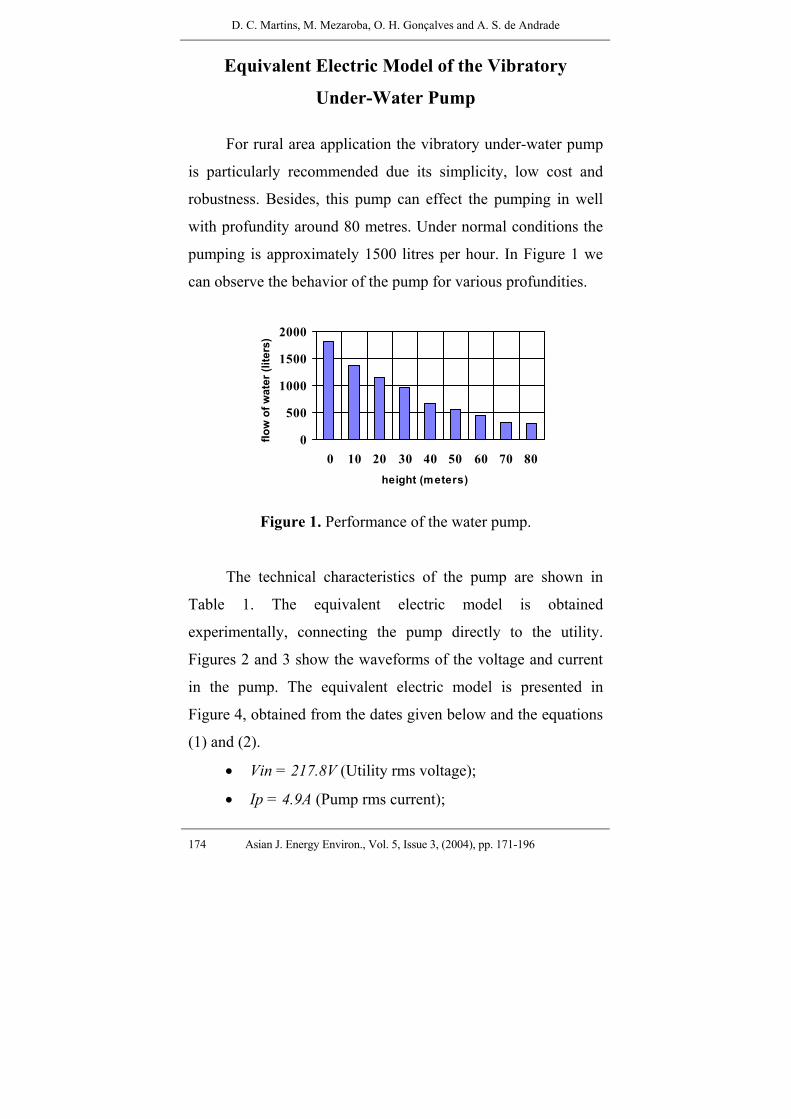
The technical characteristics of the pump are shown in
Table 1. The equivalent electric model is obtained
experimentally, connecting the pump directly to the utility.
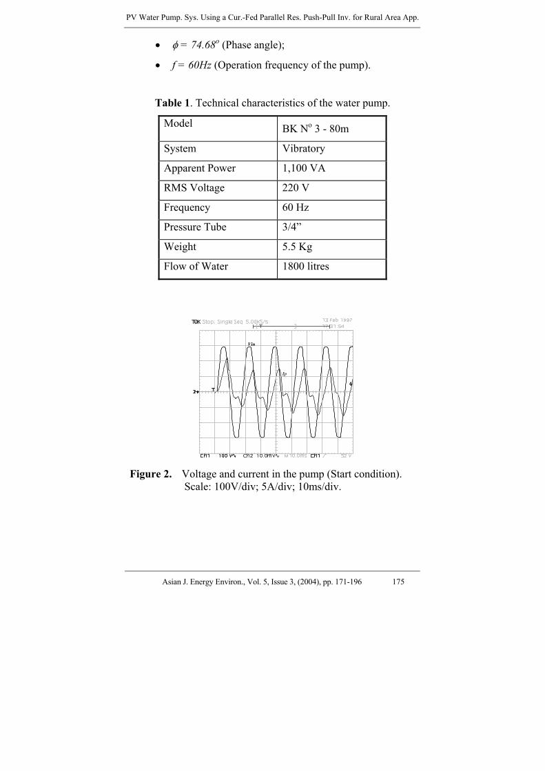
Figures 2 and 3 show the waveforms of the voltage and current
in the pump. The equivalent electric model is presented in
Figure 4, obtained from the dates given below and the equations
(1) and (2).
• Vin = 217.8V (Utility rms voltage);
• Ip = 4.9A (Pump rms current);
PV Water Pump. Sys. Using a Cur.-Fed Parallel Res. Push-Pull Inv. for Rural Area App.
Asian J. Energy Environ., Vol. 5, Issue 3, (2004), pp. 171-196 175
• φ = 74.68o (Phase angle);
• f = 60Hz (Operation frequency of the pump).
Table 1. Technical characteristics of the water pump.
Model BK No 3 - 80m
System Vibratory
Apparent Power 1,100 VA
RMS Voltage 220 V
Frequency 60 Hz
Pressure Tube 3/4”
Weight 5.5 Kg
Flow of Water 1800 litres
Vin
Ip
Figure 2. Voltage and current in the pump (Start condition). Scale: 100V/div; 5A/div; 10ms/div.
D. C. Martins, M. Mezaroba, O. H. Gonçalves and A. S. de Andrade
176 Asian J. Energy Environ., Vol. 5, Issue 3, (2004), pp. 171-196
Vin
Ip
Figure 3. Voltage and current in the pump (Steady-state condition). Scale: 100V/div; 5A/div; 5ms/div.
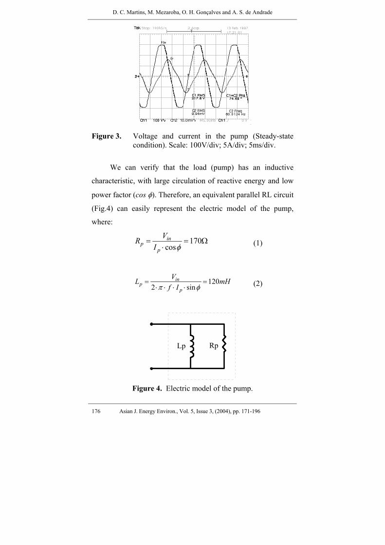
We can verify that the load (pump) has an inductive
characteristic, with large circulation of reactive energy and low
power factor (cos φ). Therefore, an equivalent parallel RL circuit
(Fig.4) can easily represent the electric model of the pump,
where:
170cosin
pp
VRI φ
= = Ω⋅
(1)
1202 sin
inp
p
VL mHf Iπ φ
= =⋅ ⋅ ⋅ ⋅
(2)
Lp Rp
Figure 4. Electric model of the pump.
PV Water Pump. Sys. Using a Cur.-Fed Parallel Res. Push-Pull Inv. for Rural Area App.
Asian J. Energy Environ., Vol. 5, Issue 3, (2004), pp. 171-196 177
Principle of Operation
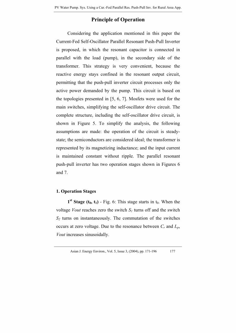
Considering the application mentioned in this paper the
Current-Fed Self-Oscillator Parallel Resonant Push-Pull Inverter
is proposed, in which the resonant capacitor is connected in
parallel with the load (pump), in the secondary side of the
transformer. This strategy is very convenient, because the
reactive energy stays confined in the resonant output circuit,
permitting that the push-pull inverter circuit processes only the
active power demanded by the pump. This circuit is based on
the topologies presented in [5, 6, 7]. Mosfets were used for the
main switches, simplifying the self-oscillator drive circuit. The
complete structure, including the self-oscillator drive circuit, is
shown in Figure 5. To simplify the analysis, the following
assumptions are made: the operation of the circuit is steady-
state; the semiconductors are considered ideal; the transformer is
represented by its magnetizing inductance; and the input current
is maintained constant without ripple. The parallel resonant
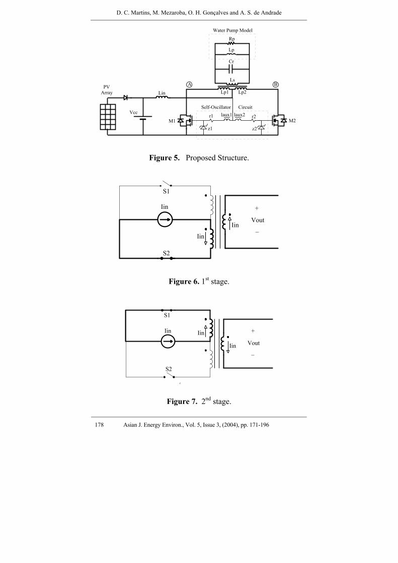
push-pull inverter has two operation stages shown in Figures 6
and 7.
1. Operation Stages
1st Stage (t0, t1) - Fig. 6: This stage starts in t0. When the
voltage Vout reaches zero the switch S1 turns off and the switch
S2 turns on instantaneously. The commutation of the switches
occurs at zero voltage. Due to the resonance between Cr and Lp,
Vout increases sinusoidally.
D. C. Martins, M. Mezaroba, O. H. Gonçalves and A. S. de Andrade
178 Asian J. Energy Environ., Vol. 5, Issue 3, (2004), pp. 171-196
_M1r1 r2laux1 laux2
z1 z2M2
Vcc
Lin
Rp
Lp
Cr
Ls
Lp1 Lp2A B
Self-Oscillator Circuit
Water Pump Model
PVArray
Figure 5. Proposed Structure.
Iin
Iin
Iin
S1
S2
+
_Vout
Figure 6. 1st stage.
Iin Iin
Iin
S1
S2
+
_Vout
Figure 7. 2nd stage.

PV Water Pump. Sys. Using a Cur.-Fed Parallel Res. Push-Pull Inv. for Rural Area App.
Asian J. Energy Environ., Vol. 5, Issue 3, (2004), pp. 171-196 179
2nd Stage (t1, t2) - Figure 7: At the time t1, the switch S2
turns off and the switch S1 turns on. The voltage Vout decreases
sinusoidally until the time t2, where a new operation period
restarts. The main waveforms are shown in Fig.8.
Is1
Is2 Vs2
Vout
to t1 t2
IinVp
Vs1
VpIin
Vp
-Vp
Figure 8. Main waveforms.
Mathematical Analysis
Before formulating a design methodology for the proposed
converter, it is necessary to develop the main circuit equations.
To simplify the mathematical analysis the following
assumptions are made: the inductor Lin is much bigger than the
inductors Lp1, Lp2; the transformer and all components are
considered ideals.
The voltage across the primary winding of the transformer
is proportional to the input voltage. Due to the modulation of the
drive circuitry with a signal from the resonant tank (Fig. 5) a
sinusoidal voltage waveform of high quality is generated from

D. C. Martins, M. Mezaroba, O. H. Gonçalves and A. S. de Andrade
180 Asian J. Energy Environ., Vol. 5, Issue 3, (2004), pp. 171-196
point A to B. The relationship between the rms voltage VAB and
the DC input voltage Vcc is given by:
( ) 2cc
AB rmsVV π⋅
= (3)
The transformer turns ratio a results in:
( )
( )
rms
AB rms
Vouta
V= (4)
where Vout(rms) is the rms output voltage. Then, all the output
impedances are referred to the primary side of the transformer as:
2
rC C a= ⋅ → reflected resonant capacitor (5)
2pL
La
= → reflected output inductor (6)
2pR
Ra
= → reflected output resistor (7)
If the transformer has a low magnetizing inductance (Lm),
it is convenient to take the equivalent inductance (Leq) as a
parallel between the magnetizing inductance and the load
inductance (Lp). However, most cases Lm >> Lp, and Leq ≈ Lp.
The simplified equivalent circuit can be observed in Figure 9.

PV Water Pump. Sys. Using a Cur.-Fed Parallel Res. Push-Pull Inv. for Rural Area App.
Asian J. Energy Environ., Vol. 5, Issue 3, (2004), pp. 171-196 181
RLC
Load
Iin
M1
M 2
A
B
Figure 9. Simplified equivalent circuit.
So, the average input current of the converter can be
expressed by:
ηπ⋅⋅⋅⋅
=p
22cc
in R2aV
I (8)
where η represents the efficiency of the converter.
The peak voltage across the switches can be determined by:
π⋅== CCABS VVV )peak()peak( (9)
From Fig. 8 the rms current through the switches can be
obtained. So:
2I
I inS )rms( = (10)
D. C. Martins, M. Mezaroba, O. H. Gonçalves and A. S. de Andrade
182 Asian J. Energy Environ., Vol. 5, Issue 3, (2004), pp. 171-196
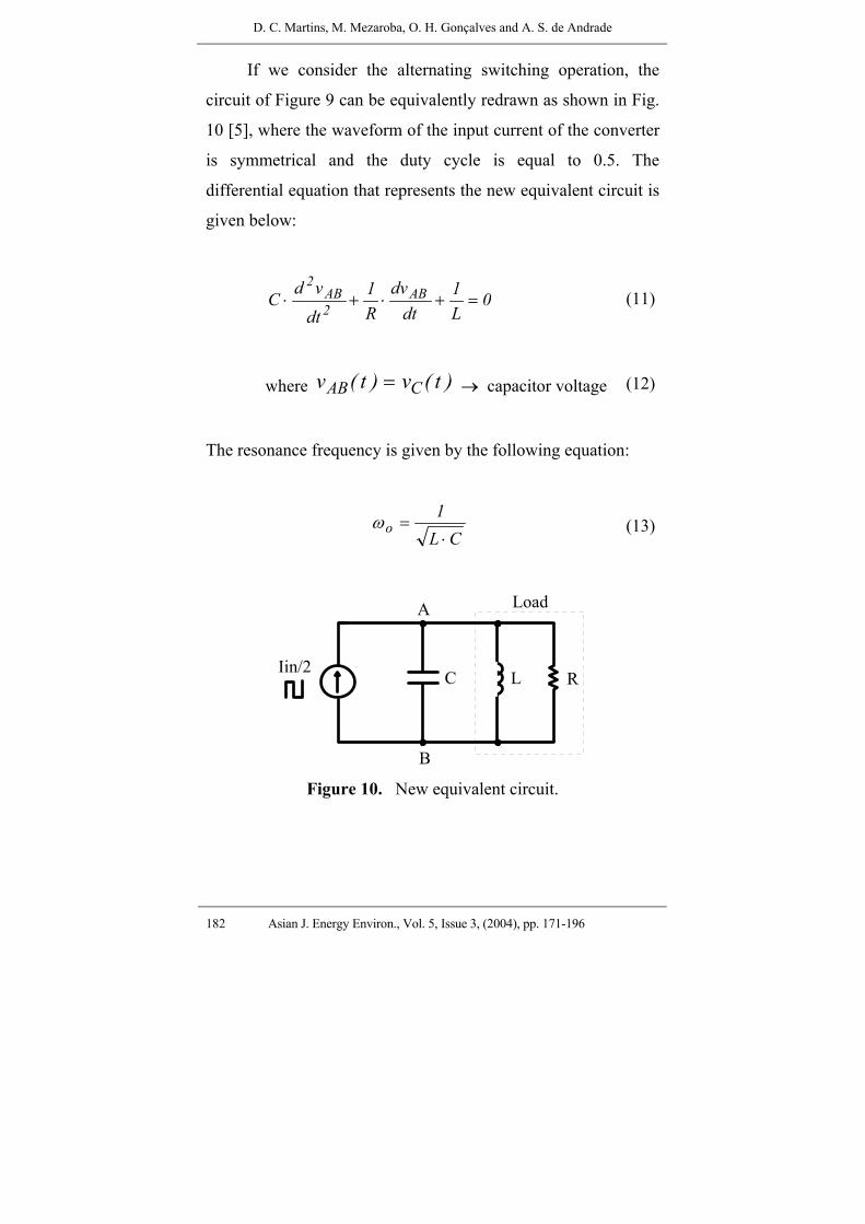
If we consider the alternating switching operation, the
circuit of Figure 9 can be equivalently redrawn as shown in Fig.
10 [5], where the waveform of the input current of the converter
is symmetrical and the duty cycle is equal to 0.5. The
differential equation that represents the new equivalent circuit is
given below:
0L1
dtdv
R1
dtvd
C AB2AB
2=+⋅+⋅ (11)
where )t(v)t(v CAB = → capacitor voltage (12)
The resonance frequency is given by the following equation:
CL1
o⋅
=ω (13)
RLC
Load
Iin/2
A
B Figure 10. New equivalent circuit.
PV Water Pump. Sys. Using a Cur.-Fed Parallel Res. Push-Pull Inv. for Rural Area App.
Asian J. Energy Environ., Vol. 5, Issue 3, (2004), pp. 171-196 183
The converter works in a ZVS condition, that is, when the
voltage across the capacitor C reaches zero the commutation
occurs. So, the initial conditions of the circuit are: 0)0(vC = ;
oLL I)0(i = .
Substituting the initial conditions in equation (11), we can
obtain the following results:
( )2 sin( )o
inL t
C t
I Iv e t
Cα ω
ω− ⋅
−⋅ ⋅
⋅ (14)
( ) 2 22 cos( ) sin( )o
inL t t
L to o
I Ii e t e t
L Cα αω αω ω
ω ω ω− ⋅ − ⋅
− − −⋅ ⋅ − ⋅ ⋅
⋅ ⋅ (15)
where: 22 2oω ω α= − ; 1
2 R Cα =
⋅ ⋅; 22
oα ω<< (16)
For each half-cycle ( 2ω ) the capacitor voltage crosses
zero. In that moment the commutation of the switches take
place.
The capacitance of the resonant capacitor is obtained
associating the equations (13) and (16). Thus:
2 4 2 2 2
2 24 16 16
8R R R LC
R Lω
ω⋅ + ⋅ − ⋅ ⋅ ⋅
=⋅ ⋅ ⋅
(17)

D. C. Martins, M. Mezaroba, O. H. Gonçalves and A. S. de Andrade
184 Asian J. Energy Environ., Vol. 5, Issue 3, (2004), pp. 171-196
Design Procedures and Example
1. Specifications
Input Data:
Vcc = 12V (Converter input voltage)
Water Pump Data:
Vout = 220 (rms voltage)
Sout = 1085 VA (apparent power)
Pout = 281 W (active power)
Lp = 120 mH (equivalent parallel inductance)
Rp = 170 Ω (equivalent parallel resistance)
f = 60 Hz (operation frequency) ⇒ ω = 377 rad/s
η = 80% (efficiency)
2. RMS VAB voltage
The rms VAB voltage is given by the following equation:
( ) 2AB rmsVccV π⋅
= = 26.65 V (18)
3. Transformer Turns Ratio (a).
( )
( )
rms
AB rms
Vouta
V= = 8.25 (19)

PV Water Pump. Sys. Using a Cur.-Fed Parallel Res. Push-Pull Inv. for Rural Area App.
Asian J. Energy Environ., Vol. 5, Issue 3, (2004), pp. 171-196 185
4. Magnetizing inductance referred to the secondary side of
the transformer (Lmsec)
secIm 0.1 SoutVout
= ⋅ (20)
secsecIm
ABrmsa VLmω⋅
=⋅
= 1.19 H (21)
where: Imsec → magnetizing current referred to the secondary
side of the transformer.
5. Input current and inductor (Iin, Lin) 2
2AB(rms)
p
V aIin
Rπ
η⋅ ⋅
=⋅ ⋅
= 29.6 A (22)
40.1
TVccLin
Iin
⋅=
⋅= 17 mH (23)
where: T = 1/f
6. Resonant Capacitor (Cr)
2 4 2 2 2
2 24. 16. 16. . .
8. . .Rp Rp Rp Leq
CrRp Leq
ωω
+ −= = 63.6 µF (24)
where: Leq = Lp//Lmsec

D. C. Martins, M. Mezaroba, O. H. Gonçalves and A. S. de Andrade
186 Asian J. Energy Environ., Vol. 5, Issue 3, (2004), pp. 171-196
7. Number of Parallel Batteries
The average power and current delivered by the batteries
will be:
BavPoutPη
= ≅ 350W (25)
BavBav
PIVcc
= ≅ 30A (26)
The number of parallel batteries is given by:
A BavB
c
B INB⋅
= = 1.5 batteries (27)
where:
NB → minimum number of parallel batteries,
BA → battery autonomy: 3 hours,
BC → battery capacity: 60Ah (one-hour rate).
Two lead-acid batteries (12V - 100Ah (20 hours rate)) were
chosen.
8. Number of Photovoltaic Modules
The photovoltaic modules used in the design can deliver
3Ah (Ampere-hours) with a solar radiation of 1.000 W/m2. In
the worst case the average solar radiation, in our region
(Florianópolis/Santa Catarina – Brazil), is about 2500 W/m2 per
day. Thus:
PV Water Pump. Sys. Using a Cur.-Fed Parallel Res. Push-Pull Inv. for Rural Area App.
Asian J. Energy Environ., Vol. 5, Issue 3, (2004), pp. 171-196 187
Rs avd
s
I RAhR⋅
= = 7.5 Ah (28)
where:
Ahd → Ampere-hours delivery per photovoltaic module for one
day.
Rav → average solar radiation: 2500 W/m2 / day (worst
situation),
RS → standard solar radiation: 1000 W/m2,
IRS → delivery of current by the photovoltaic module for the
Rav radiation: 3Ah.
Thus, the number of photovoltaic modules is given by:
NpAhAh
L
d= = 4 photovoltaic modules (29)
where: AhL → Ampere-hours delivery to the load per day.
Simulation Results
In order to evaluate the employed methodology, some
numerical simulations of the system were made using the
PSPICE program [9], following the same specifications and the
same design outlined in the preceding section.
D. C. Martins, M. Mezaroba, O. H. Gonçalves and A. S. de Andrade
188 Asian J. Energy Environ., Vol. 5, Issue 3, (2004), pp. 171-196
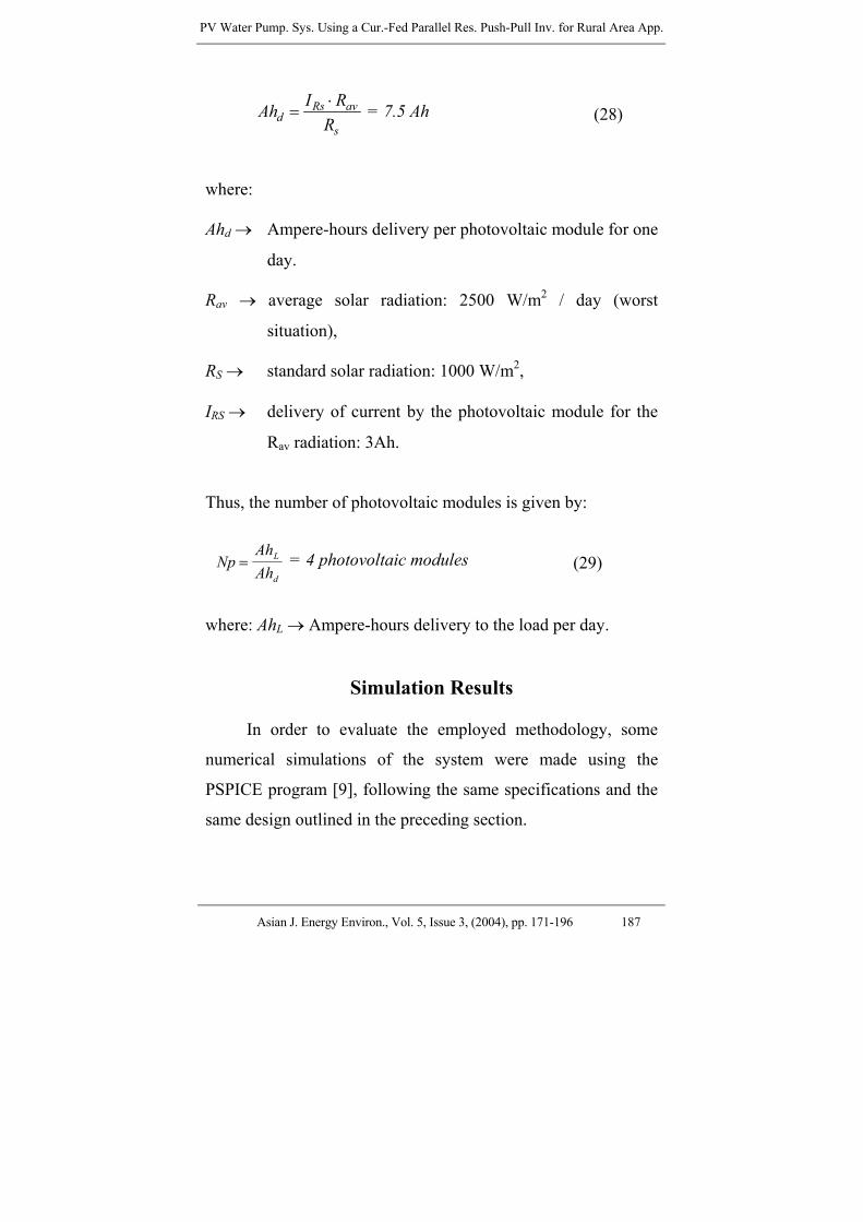
The main results are shown in the following figures:
0ms 20ms 40ms 60ms 80ms 100ms
500
0
-500
Vout
Iout*30
Figure 11. Voltage and current in the pump (Start-transient).
200ms 205ms 210ms 215ms 220ms
300
200
100
-0
-100
-200
-300
Vout
Iout*30
Figure 12. Voltage and current in the pump (Steady-state condition).
0ms 20ms 40ms 60ms 80ms 100ms
80
60
40
20
0
-20
Vds
Im1
Figure 13. Voltage and current in the main switches (Start-transient).

PV Water Pump. Sys. Using a Cur.-Fed Parallel Res. Push-Pull Inv. for Rural Area App.
Asian J. Energy Environ., Vol. 5, Issue 3, (2004), pp. 171-196 189
0ms 20ms 40ms 60ms 80ms 100ms
500
0
-500
Vout
Icr * 30
Figure 14. Voltage and current in the resonant capacitor (Start transient).
Vcc
Iin
Figure 15. Voltage and current in the batteries (Start-transient) Scales: 10V/div; 20A/div; 10ms/div.
Iin
Vcc
Figure16. Voltage and current in the batteries (Steady-state condition) Scale: 10V/div; 10A/div; 2ms/div.
D. C. Martins, M. Mezaroba, O. H. Gonçalves and A. S. de Andrade
190 Asian J. Energy Environ., Vol. 5, Issue 3, (2004), pp. 171-196
Vout
Iout
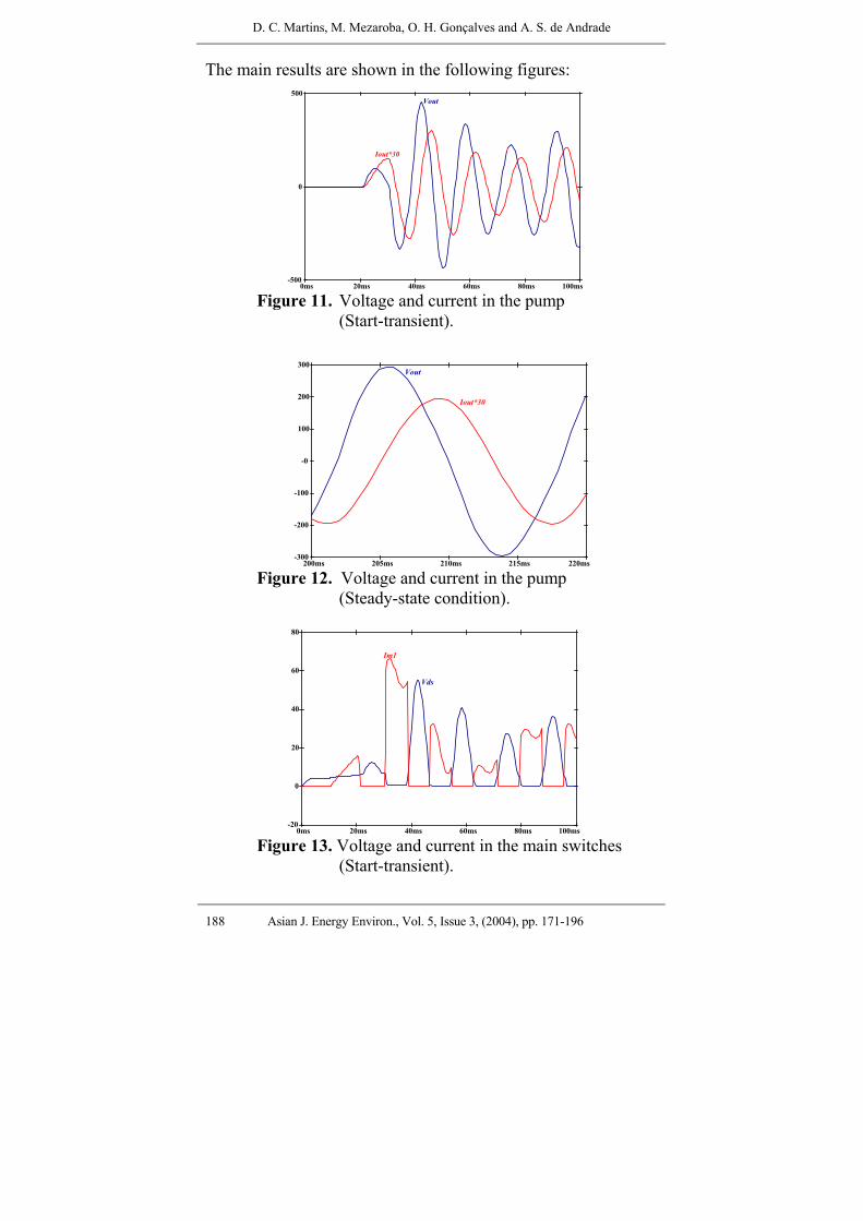
Figure 17. Voltage and current in the pump
(Start-transient) Scale: 100V/div; 5A/div; 10ms/div.
Vout
Iout
Figure 18. Voltage and current in the pump (Steady-state condition) Scale: 100V/div; 5A/div; 2ms/div.

PV Water Pump. Sys. Using a Cur.-Fed Parallel Res. Push-Pull Inv. for Rural Area App.
Asian J. Energy Environ., Vol. 5, Issue 3, (2004), pp. 171-196 191
Im1
Vds
Figure 19. Voltage and current in the main switches
(Start-tranient). Scale: 10V/div; 20A/div; 10ms/div.
Im1
Vds
Figure 20. Voltage and current in the main switches
(Steady-state condition) Scale: 10V/div; 10A/div; 2ms/div.

D. C. Martins, M. Mezaroba, O. H. Gonçalves and A. S. de Andrade
192 Asian J. Energy Environ., Vol. 5, Issue 3, (2004), pp. 171-196
Vout
Icr
Figure 21. Voltage and current in the resonant capacitor
(Start-transient). Scale: 100V/div; 5A/div; 10ms/div.
Vout
Icr
Figure 22. Voltage and current in the resonant capacitor
(Steady-state condition) Scale: 100V/div; 5A/div; 2ms/div

PV Water Pump. Sys. Using a Cur.-Fed Parallel Res. Push-Pull Inv. for Rural Area App.
Asian J. Energy Environ., Vol. 5, Issue 3, (2004), pp. 171-196 193
VoutIsec
Figure 23. Voltage and current in the secondary
Side of the transformer (Start-transient). Scale: 100V/div; 2A/div; 10ms/div
Vout
Isec
Figure 24. Voltage and current in the Secondary side of the transformer (Steady-state). 100V/div; 1A/div; 2ms/div.
D. C. Martins, M. Mezaroba, O. H. Gonçalves and A. S. de Andrade
194 Asian J. Energy Environ., Vol. 5, Issue 3, (2004), pp. 171-196
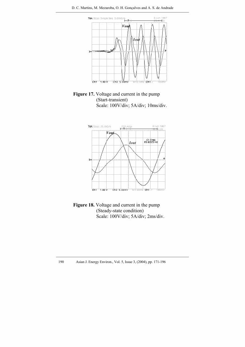
Figure 25. Output voltage harmonic analysis.
Figure 26. Harmonic analysis of the pump current.
Figures 15 and 16 show the voltage and current in the
batteries in the start-transient conditions and steady-state
conditions, respectively. The experimental results of the
converter show that the voltage across the pump is practically
sinusoidal (Fig. 18), with low harmonic distortion (Fig. 25 and
26), and the self-oscillator drive circuit presented good behavior
for this application. Besides, the over-voltage across the pump
and the Mosfets does not put at risk the structure (Figs. 17, 19
and 20). The start current of the converter is inside the limit
specified by the manufacturer of the switches. Figs. 21 and 22
present the voltage and current in the resonant capacitor. The
behavior of the voltage and current in the secondary side of the
transformer is presented in Figure 23 and in Figure 24.

PV Water Pump. Sys. Using a Cur.-Fed Parallel Res. Push-Pull Inv. for Rural Area App.
Asian J. Energy Environ., Vol. 5, Issue 3, (2004), pp. 171-196 195
An efficiency of 91% was obtained at full load condition.
Conclusions
In this paper the analysis of a water pumping system from
photovoltaic cells using a current-fed self-oscillator parallel
resonant push-pull inverter operating a vibratory under-water
pump, for residential applications in rural areas was presented.
The converter is shown to be extremely well adapted to this kind
of pump, providing sinusoidal voltage with low harmonic
distortion without the necessity of any type of modulation.
According to the results obtained we have a DC-AC converter
with the following features: it is particularly simple and robust,
it uses low cost technology, it can operate with only one power
processing stage, it has a simple control circuit with its terminals
earthed in the same grounding, low harmonic distortion of the
load voltage, natural isolation and low number of control
switches.
Therefore, the authors believe that this technology can be
very useful for some rural residential applications.
References
[1] Muljadi, E. (1997) PV Water Pumping with a Peak-Power Tracker Using a Simple Six-Step Square-Wave Inverter, IEEE Trans. on Industry Applications, 33 (3), May/June, 714-721.
D. C. Martins, M. Mezaroba, O. H. Gonçalves and A. S. de Andrade
196 Asian J. Energy Environ., Vol. 5, Issue 3, (2004), pp. 171-196
[2] Slabbert, C. and Malengret, M. (1998) Grid Connected/ Solar Water Pump for Rural Areas, Proc. IEEE-ISIE’98, 1, 31-34.
[3] Van der Merwe, L. and Van der Merwe, G. J. (1998) Universal Converter for DC PV Water Pumping System, IEEE-IECON’98, 1, 218-223.
[4] Moechtar, M., Juwono, M. & Kantosa, E. (1991) Performance Evaluation of AC and DC Direct Coupled Photovoltaic Water Pumping Systems, Energy Conservation and Management Journal, 31 (6), 521-527.
[5] Lee, C. H., Joung,G. B, Cho, G. H. (1990) A Unity Power Factor High Frequency Parallel Resonant Electronic Ballast, IEEE-IAS, 2, 1149-1156.
[6] Brüning, G. (1986) A Comparative Introduction of a New High Voltage Resonant Oscillator, IEEE-APEC’86, 1, 76-82.
[7] Brüning, G. (1986) A New High-Voltage Oscillator, IEEE Trans. on Industrial Electronics, IE-33 (2), May, 171-175.
[8] Mezaroba, M. (1998) Water Pumping System Using the Solar Energy From Photovoltaic Panels Array, Master Thesis, INEP/EEL/UFSC, Florianópolis, SC, Brazil.
[9] Pspice Circuit Analysis (1989), Microsim Corporation, version 4.05.