punching shear based design of concrete-filled chs t
TRANSCRIPT

12th International Conference on Advances in Steel-Concrete Composite Structures (ASCCS 2018) Universitat Politècnica de València, València, Spain, June 27-29, 2018
Doi: http://dx.doi.org/10.4995/ASCCS2018.2018.7513
2018, Universitat Politècnica de València
Punching Shear Based Design of Concrete-Filled CHS T-Joints under In-Plane Bending
F. Xua,b,c,*, T.M. Chana,b and J. Chenc
aDepartment of Civil and Environmental Engineering, The Hong Kong Polytechnic University, Hong Kong, China
bChinese National Engineering Research Centre for Steel Construction (Hong Kong Branch), The Hong Kong Polytechnic University, Hong Kong, China
cInstitute of Structural Engineering, Zhejiang University, Hangzhou, Zhejiang, China
*corresponding author, e-mail address: [email protected]
Abstract The in-plane bending behaviour of concrete-filled circular hollow section (CHS) T-joints was examined in this paper. The main failure mode, the punching shear of the chord-wall, was observed from the test of four large-scale joints with the diameter ratio of brace to chord (β) ranging from 0.44 to 0.85. The tube-wall deformation was measured to assess the governing failure mode of the composite joints. Complementary finite element (FE) methodology was verified against the experimental findings and the validated FE models were used to further investigate the mechanical behaviour and the design methodology. The feasibility to apply a fracture criterion in the material-level to a large-scale structural simulation was evaluated. The validated FE modes could successfully capture the tube-wall fracture initiation and propagation. Based on both experimental and numerical investigations, it was shown that the capacity of composite joints was governed by the ultimate strength limit, i.e. punching shear strength, due to the infill concrete that mitigated both inward and outward deformation on the compressive and tensile sides, respectively. The analytical model was established to reveal the composite actions between the tube and the inner concrete, and to elaborate the development of the flexural section-resistance. Finally, the design equation was proposed and could well predict the moment capacity.
Keywords: Concrete-filled steel tube; Tubular joint; In-plane bending; Fracture; Punching shear; Design.
1. Introduction
Concrete-filled steel tubular (CFST) structures are widely adopted in buildings, bridges, marine infrastructures and transmission towers. The infill concrete of a CFST member would significantly improve the local buckling resistance [1-3] especially for those with large diameter-to-thickness ratios. In transmission towers, poles and arch bridges [4], hollow or CFST chords and braces are commonly connected by welds. Previous investigations [5-9] demonstrated the radial stuffiness of chord member and the capacity of composite joints could be significantly improved when compared with the hollow section counterparts, despite that the inner concrete does not provide the direct tensile or compressive resistance to the external actions. The typical failure modes of composite joints were brace failure [5,6] and crushing of
inner concrete [5,7] in the case of axial compression and punching shear in the case of axial tension [6-9].
In some scenarios, those composite joints would also be subjected to the external moment loading. In the electrical transmission engineering, the hollow horizontal branches which are welded to the CFST transmission poles will also support the gravity load of the electrical conductors and the ice-load. These types of loads will introduce a moment force to the connecting area. However, limited studies [6] have been reported on the structural performance of in-plane bending loaded concrete-filled or grouted circular hollow section (CHS) joints and the design provisions for concrete-filled CHS joints subjected to in-plane bending is currently scarce. Therefore, this paper aims to assess the governing failure mode
573

Xu, F., Chan, T.M. and Chen, J.
2018, Universitat Politècnica de València
(modes) and develop the corresponding design method for those moment-resisting composite joints through experimental, numerical and analytical investigations.
2. Experimental Investigation
2.1. Test set-up and specimens Four large-scale specimens were tested under
in-plane bending. The measured geometries (D, t, Db, tb) are shown in Table 1. The steel CHS tubes filled with self-compacting concrete were used for chord members, whilst the brace members were fabricated from plain CHS tubes. The details of joint specimens and test set-up are as shown in Fig. 1.
Fig. 1. Test set-up for specimens subjected to in-plane bending (Unit: mm).
Table 1. Measured geometries, ultimate strengths and failure modes of the test specimens.
Specimens Chord Brace MExp
kN·m MFEA / MExp
Mu/ MExp
Failure mode D
mm t
mm L
mm Db
mm tb
mm Lb
mm T-300-4-133-6 298.8 4.09 2002.1 50.72 0.85 630.2 50.72 0.85 0.64 CPS T-300-5-133-6 301.3 5.04 2001.8 52.98 0.95 630.4 52.98 0.95 0.72 CPS T-240-4-203-8 238.8 3.93 2001.3 108.90 1.06 630.1 108.90 1.06 0.93 CPS T-240-5-203-8 241.2 4.95 2000.9 124.93 1.03 630.1 124.93 1.03 0.96 CPS
Mean 0.97 0.81 Note: CPS: chord-wall punching shear failure.
The steel mechanical properties are summarized in Table 2 and the 150-mm cubic compressive strength (fcu) and Young’s modulus (Ec) of inner concrete after 28 days were 56.3 MPa and 34.1 GPa, respectively. The test specimens were labeled as the order of the joint type, the chord diameter, the chord-wall thickness, the brace diameter and the brace-wall thickness. For example, the label “T-300-4-133-6” defines a T-joint with a nominal outer chord diameter of 300 mm, nominal chord thickness of 4 mm, nominal outer brace diameter of 133 mm and nominal brace thickness of 6 mm.
The moment applied on the test specimens was evaluated as the applied tensile load multiplying its force arm 630 mm. The in-plane bending load was applied by a 1,000kN-tension-capacity MTS actuator controlled by the displacement at a constant speed of 0.5 mm/min for all test specimens. The chord-wall deformations, 15 mm from the weld toe, were measured by LVDTs and the measurement arrangements are shown in Fig. 1. The date-acquisition frequency at 1 Hz was used during the
whole test for the record of both applied load and displacements of transducers.
Table 2. Measured mechanical properties of steel.
Steel Nominal thickness
(mm)
fy (MPa)
fu (MPa)
Es (GPa)
εf (%)
Chord
4.0 452 547 204 27.7 5.0 385 513 204 31.8
Brace
6.0 408 549 200 32.0 8.0 436 520 202 33.7
2.2. Test results and discussion The chord-wall punching shear failure at the
crown of the tensile side was observed and resulted the failure of composite joints. No obvious yield-line was observed on the chord wall near the weld toe until the load exceeded 85% of the ultimate strength. The failure mode of composite joints was not affected by the chord-wall slenderness (D/t) and diameter ratio between brace and chord (Db/D) in the test. The typical failure mode of specimens T-240-4-203-8 and T-300-4-133-6 are shown in Fig. 2.
574

Xu, F., Chan, T.M. and Chen, J.
2018, Universitat Politècnica de València
(a) Test specimen T-240-4-203-8
(b) Test specimen T-300-4-133-6
Fig. 2. Punching shear failure mode. (left: experiment; right simulation)
Fig. 3. Moment-deformation curves.
The ultimate moment resistances (FExp×630, N·mm) for each test specimen are summarized in Table 1. The load - deformation (ΔB) curves are plotted in Fig. 3 as solid lines. The deformation, ΔB, was donated to the measured displacement difference between points B and B1, as shown in Fig. 1. It is shown that the chord-wall thickness has some effects on its deformation. The deformation of specimens with 5-mm-chord-wall was less than those with 4-mm-chord-wall at the same load, while the maximum deformations were similar for joints with the same chord diameter. All the chord deformations at the peak load were less than the 3% deformation limit specified in the CIDECT-1 [10] recommendations as compared in Fig. 3. It is suggested in CIDECT-1 [10] for plain CHS joints under the strength limit state, the corresponding deformation at the peak loads in their load- deformation curves should be less than 3% D (0.03D), otherwise the joint capacity is the load corresponding to the deformation of 3% D (0.03D) which is called the deformation limit of 3% D. Therefore, the deformation criterion
recommended by CIDECT-1 [10] is generally satisfied and the governing limit state for composite joints is the ultimate strength.
3. Finite Element Analyses
3.1. General Description The finite element analysis (FEA) was
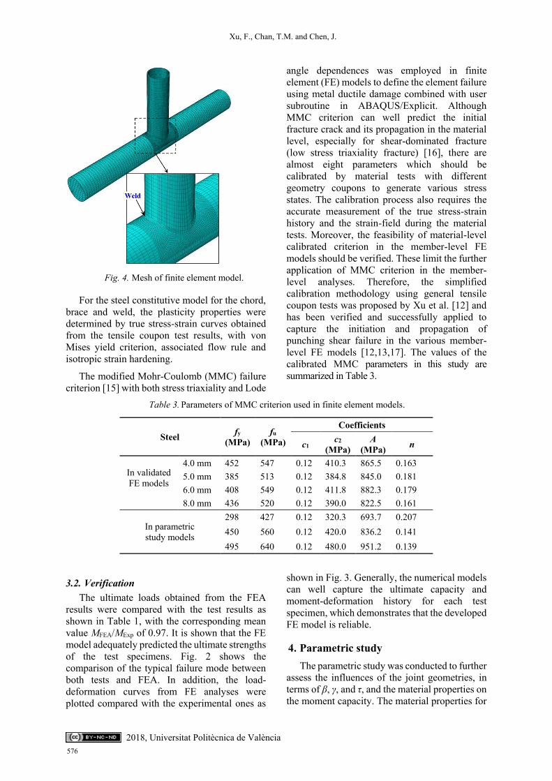
conducted by ABAQUS/Explicit (6.10) [11] solution technique since it allows finite element (FE) models to be discontinued which offers the possibility of visible “fracture crack” development when the material failure criterion is defined, by means of deleting elements from mesh. The solid element, C3D8R, was used to model the steel tube, weld and inner concrete. Though the convergence problem was not expected to occur, the sensitivity analysis on mesh was also conducted [12,13] to find an appropriate element size with both accurate simulation result and acceptable computational time, since element size would also affect the stable increment of FE model in ABAQUS/Explicit. Therefore, the total number of elements was approximately 50,000 for the concrete part and 29,000 for the steel tubular joint part. Typical finite element mesh of concrete-filled CHS joint is shown in Fig. 4. Furthermore, the propriate fixed mass scaling factor (MSF) was assessed [12,13] and the value of 106 was employed into the models at beginning to achieve both computational efficiency and the calculation accuracy. The boundary condition was set as the test and the moment load was applied by the tensile force on the end of brace member at a speed of 0.5 mm/min as it in the test.
The concrete-damaged plasticity model (ABAQUS 6.10) was employed for the inner concrete. The yield surface was described by a series of constant values of 30°, 0.1, 1.16, 0.667 and 0.00025 for dilation angle, flow potential eccentricity, ratio of the compressive strength under biaxial loading to uniaxial compressive strength, the ratio of the second stress invariant on the tensile meridian to that on the compressive meridian, and viscosity parameter, respectively. The elastic modulus and Poison’s ratio were taken as 4700√𝑓c and 0.2; whilst the uniaxial stress-strain relationship and tensile behaviour of inner concrete were determined according to Xu et al. [14]. The hard contact model and Coulomb friction model with the coefficient of 0.6 were employed in the normal and tangential directions, respectively.
575
Xu, F., Chan, T.M. and Chen, J.
Fig. 4. Mesh of finite element model.
For the steel constitutive model for the chord, brace and weld, the plasticity properties were determined by true stress-strain curves obtained from the tensile coupon test results, with von Mises yield criterion, associated flow rule and isotropic strain hardening.
The modified Mohr-Coulomb (MMC) failure criterion [15] with both stress triaxiality and Lode
angle dependences was employed in finite element (FE) models to define the element failure using metal ductile damage combined with user subroutine in ABAQUS/Explicit. Although MMC criterion can well predict the initial fracture crack and its propagation in the material level, especially for shear-dominated fracture (low stress triaxiality fracture) [16], there are almost eight parameters which should be calibrated by material tests with different geometry coupons to generate various stress states. The calibration process also requires the accurate measurement of the true stress-strain history and the strain-field during the material tests. Moreover, the feasibility of material-level calibrated criterion in the member-level FE models should be verified. These limit the further application of MMC criterion in the member-level analyses. Therefore, the simplified calibration methodology using general tensile coupon tests was proposed by Xu et al. [12] and has been verified and successfully applied to capture the initiation and propagation of punching shear failure in the various member-level FE models [12,13,17]. The values of the calibrated MMC parameters in this study are summarized in Table 3.
Table 3. Parameters of MMC criterion used in finite element models.
Steel fy (MPa)
fu (MPa)
Coefficients
c1 c2 (MPa)
A (MPa) n
In validated FE models
4.0 mm 452 547 0.12 410.3 865.5 0.163 5.0 mm 385 513 0.12 384.8 845.0 0.181 6.0 mm 408 549 0.12 411.8 882.3 0.179 8.0 mm 436 520 0.12 390.0 822.5 0.161
In parametric study models
298 427 0.12 320.3 693.7 0.207 450 560 0.12 420.0 836.2 0.141 495 640 0.12 480.0 951.2 0.139
3.2. Verification The ultimate loads obtained from the FEA
results were compared with the test results as shown in Table 1, with the corresponding mean value MFEA/MExp of 0.97. It is shown that the FE model adequately predicted the ultimate strengths of the test specimens. Fig. 2 shows the comparison of the typical failure mode between both tests and FEA. In addition, the load-deformation curves from FE analyses were plotted compared with the experimental ones as
shown in Fig. 3. Generally, the numerical models can well capture the ultimate capacity and moment-deformation history for each test specimen, which demonstrates that the developed FE model is reliable.
4. Parametric study The parametric study was conducted to further
assess the influences of the joint geometries, in terms of β, γ, and τ, and the material properties on the moment capacity. The material properties for
576 2018, Universitat Politècnica de València

Xu, F., Chan, T.M. and Chen, J.
2018, Universitat Politècnica de València
the chord and brace members, if not specially mentioned, were determined as 204 GPa for Young’s modulus; 450 MPa for yield strength and 560MPa for ultimate strength. To obtain the failure mode in the connecting region, the braces in some parametric models were strengthened to ensure the adequate flexural strength of the member itself. The detailed joint geometric properties are also presented in Figs 5~9.
Figs. 5 and 6 manifest when the diameter of the chord keeps constant, the moment capacity at fracture increases with the diameter ratio of the brace to the chord (β); while the capacity decreases with the increase of chord diameter-to-thickness ratio (γ). When the β value increased, both failure area and inter force arm in the moment resistant plane will increase for a given chord member. Moreover, for a give chord-diameter, the increased γ value results in a reduced fracture failure area. It should be noted that the tendency of the punching shear capacity with both β and γ values are not linear, which can be partly attributed to the composite actions and the participant of inner concrete in the moment-resistance as the local bearing in the compressive region [12]. The minor influence of the thickness ratio of brace to chord (τ) was manifested in Fig. 7. The τ value varied with the brace-thickness when the parameter values of β and γ keep fixed. The punching shear strength slightly increased with the τ value which can be attributed to the thick brace-wall can help to develop a large local bearing region on inner concrete, indirectly improving the sectional moment resistance.
Fig. 5. Relationship of moment capacity and β.
Fig. 6. Relationship of moment capacity and γ.
Fig. 7. Relationship of moment capacity and τ.
The influence of the chord-wall material property with respect to the yield strength and ultimate strength was evaluated in the typical joints of T-300-4-140-6 and T-300-4-180-6. The moment capacity increases with the material strength as shown in Fig. 8. Moreover, it can be found in Fig. 9 the ratios of moment capacity to steel ultimate strength are almost invariant, which indicates the punching shear capacity possesses a strong dependence with the ultimate strength of chord-wall.
Fig. 8. Relationship of moment capacity and
material property.
577
Xu, F., Chan, T.M. and Chen, J.
Fig. 9. Ratios of moment to material strength.
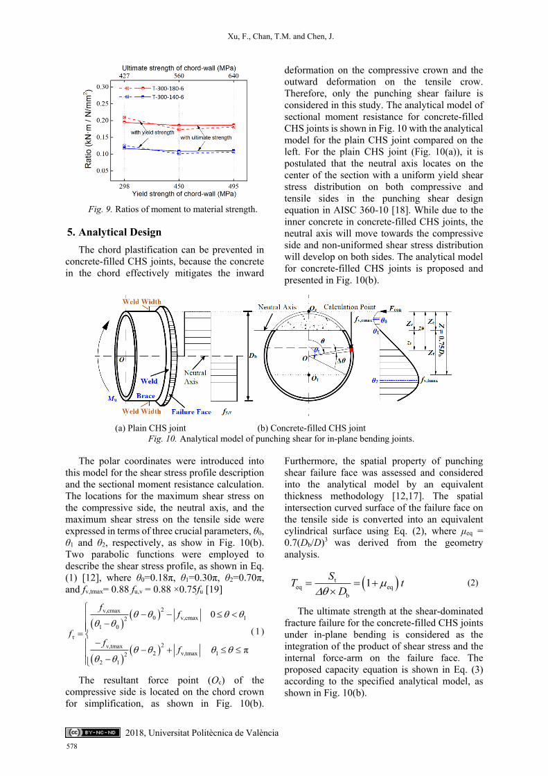
5. Analytical Design The chord plastification can be prevented in
concrete-filled CHS joints, because the concrete in the chord effectively mitigates the inward
deformation on the compressive crown and the outward deformation on the tensile crow. Therefore, only the punching shear failure is considered in this study. The analytical model of sectional moment resistance for concrete-filled CHS joints is shown in Fig. 10 with the analytical model for the plain CHS joint compared on the left. For the plain CHS joint (Fig. 10(a)), it is postulated that the neutral axis locates on the center of the section with a uniform yield shear stress distribution on both compressive and tensile sides in the punching shear design equation in AISC 360-10 [18]. While due to the inner concrete in concrete-filled CHS joints, the neutral axis will move towards the compressive side and non-uniformed shear stress distribution will develop on both sides. The analytical model for concrete-filled CHS joints is proposed and presented in Fig. 10(b).
(a) Plain CHS joint (b) Concrete-filled CHS joint
Fig. 10. Analytical model of punching shear for in-plane bending joints.
The polar coordinates were introduced into this model for the shear stress profile description and the sectional moment resistance calculation. The locations for the maximum shear stress on the compressive side, the neutral axis, and the maximum shear stress on the tensile side were expressed in terms of three crucial parameters, θ0, θ1 and θ2, respectively, as show in Fig. 10(b). Two parabolic functions were employed to describe the shear stress profile, as shown in Eq. (1) [12], where θ0=0.18π, θ1=0.30π, θ2=0.70π, and fv,tmax= 0.88 fu,v = 0.88 ×0.75fu [19]
2v,cmax0 v,cmax 12
1 0τ
2v,tmax2 v,tmax 12
2 1
0
π
ff
ff
f
( 1 )
The resultant force point (Oc) of the compressive side is located on the chord crown for simplification, as shown in Fig. 10(b).
Furthermore, the spatial property of punching shear failure face was assessed and considered into the analytical model by an equivalent thickness methodology [12,17]. The spatial intersection curved surface of the failure face on the tensile side is converted into an equivalent cylindrical surface using Eq. (2), where μeq = 0.7(Db/D)3 was derived from the geometry analysis.
teq eq
b
1ST tD
(2)
The ultimate strength at the shear-dominated fracture failure for the concrete-filled CHS joints under in-plane bending is considered as the integration of the product of shear stress and the internal force-arm on the failure face. The proposed capacity equation is shown in Eq. (3) according to the specified analytical model, as shown in Fig. 10(b).
578 2018, Universitat Politècnica de València

Xu, F., Chan, T.M. and Chen, J.
2018, Universitat Politècnica de València
eq
u τ θ eqΣ
32b
u b
d
0.79 0.56
M f z S
D f D tD
(3)
where Mu is the ultimate moment strength; fτ is shear stress distribution function, expressed by Eq. (1); Db is the brace diameter; D is the chord diameter; fu is the steel ultimate tensile strength for the chord; t is the chord-wall thickness.
The ultimate strengths predicted by Eq. (3) for T-joints (Mu) are compared with the experimental and FEA results in Table 1 and Fig. 11, with the mean value of Mu/MExp (Table 1) and Mu/MFEA
(Fig. 11) being 0.81 and 0.80, respectively. In general, the proposed design equation gives a conservative prediction for the ultimate moment capacity of the composite T-joints. This result may be attributed to neglecting the weld effects in the proposed analytical model. However, the influence of weld width will significantly decrease as the brace diameter increases. The absence of weld width in capacity calculation can be considered as the safety reserve for the sudden tube-wall fracture failure. In addition, FE models without welds were also established and the results were compared with the predictions from the proposed equation. The comparison between calculated and numerical results, as shown in Fig. 11, demonstrates a good correlation with the mean value of Mu/MFEA being 0.97.
Fig. 11. Comparison of moment capacities
predicted by the proposed equation and FEA.
It should be noted that some parameters used in the deduction procedure for the proposed design equation, Eq. (3), are derived from the numerical analysis. Therefore, the applicable
range should be in accordance with the parametric study, namely 0.20 ≤ β ≤ 0.60, 30.0 ≤ γ ≤ 75.0.
6. Conclusions Experimental and numerical studies were
conducted on the mechanical behaviour of concrete-filled CHS joints subjected to in-plane bending. All the test specimens failed in punching shear and the 3%D deformation limit recommended by CIDECT-1 [10] was generally satisfied. It has been shown that the inner concrete effectively supports the chord wall in the compressive side, which means the contributions from the concrete should be considered in the sectional moment resistance. The fracture criterion in the material-level was successfully adopted into the FE models and was validated in the member-level. On the basis of both experimental and numerical investigations, the analytical design methodology based on metal fracture mechanism for composite tubular joints were proposed. The design predictions agreed well with both the test and FEA results, manifesting a satisfactory accuracy.
References [1] O’Shea MD, Bridge RQ. Design of circular thin-
walled concrete filled steel tubes. J Struct Eng 2000; 126(1):1295-1303.
[2] Uy B. Local and postlocal buckling of fabricated steel and composite cross sections. J Struct Eng 2001;127(6):666–677.
[3] Bradford MA, Loh HY, Uy B. Slenderness limits for filled circular steel tubes. J Constr Steel Res 2002; 58(2):243-252.
[4] Chen BC, Wang TL. Overview of concrete filled steel tube arch bridges in China. Practice periodical on structural design and construction-ASCE 2009; 14(2):70-80.
[5] Feng R, Young B. Tests of concrete-filled stainless steel tubular T-joints. J Constr Steel Res 2008; 64(11): 1283-1293.
[6] Tebbett IE, Beckett CD, Billington CJ. The punching shear strength of tubular joints reinforced with a grouted pile. Offshore Technology Conference 1979; 915–921.
[7] Packer JA. Concrete-filled HSS connections. J Struct Eng 1995; 121(3):458-467.
[8] Xu F, Chen J, Jin WL. Experimental investigation and design of concrete-filled steel tubular CHS connections. J Struct Eng 2014; 141(2): 04014106.
[9] Huang W, Fenu L, Chen B, et al. Experimental study on K-joints of concrete-filled steel tubular
579

Xu, F., Chan, T.M. and Chen, J.
truss structures. J Constr Steel Res 2015; 107: 182-193.
[10] Wardenier J, Kurobane Y, Packer JA, van der Vegte GJ, Zhao X-L. Design guide for circular hollow section (CHS) joints under predominantly static loading, 2nd Ed., CIDECT-1. Comité International pour le Développement et l’Étude de la Construction Tubulaire, LSS Verlag, Germany; 2008.
[11] ABAQUS 6.10 [Computer software]. Dassault systems, Waltham, MA, USA; 2010.
[12] Xu F, Chen J and Chan TM. Mechanical Behaviour of concrete-filled CHS connections subjected to in-plane bending. Eng Struct 2017;148:101-112.
[13] Xu F, Chen J and Chan TM. Numerical Analysis and punching shear fracture based design of longitudinal plate to concrete-filled CHS connections. Construction and Building Materials 2017; 156: 91-106.
[14] Xu F, Chen J and Chan TM. Numerical investigation on compressive performance of CFST columns with encased built-up lattice-angles. J Constr Steel Res 2017; 137:242-253.
[15] Bai Y, Wierzbicki T. Application of extended Mohr-Coulomb criterion to ductile fracture. Int J Fract 2010; 161(1):1-20.
[16] Bai Y, Wierzbicki T. A comparative study of three groups of ductile fracture loci in the 3D space. Eng Fract Mech 2015; 135:147-167.
[17] Xu F, Chen J and Jin WL. Punching shear failure of concrete-filled steel tubular CHS connections. J Constr Steel Res 2016; 124:113-121.
[18] ANSI/AISC 360-10. Specification for structural steel buildings. Chicago, USA: America Institute of Steel Construction (AISC); 2010.
[19] John MA, Franklin DJ, Henry HR. Guide to the use of tables and formulas in machinery’s handbook, 28th Ed., Industrial Press, New York, USA; 2008.
580 2018, Universitat Politècnica de València