pulselarsen antennas | pulselarsen antennas - …...choosing the proper antenna for any application...
TRANSCRIPT

ISO 9001 Certified / RoHS Compliant
Amateur Antenna ProductsVolume 2

www.pulseelectronics.com/products/antennas
Larsen - a Pulse Brand - is pleased to bring you the new Amateur Catalog. The goal of the catalog is to provide you with a “go to” source for all your amateur needs. Here you will find our most
popular Portable Radio, Low/Mid Band, VHF, UHF and small Base Station antennas along with the cable assemblies, mounting brackets, replacement parts and accessories to support them.
Larsen is a brand of Pulse Engineering. Headquartered in San Diego, California, Pulse is a worldwide leader in electronic component and subassembly design and manufacturing. Pulse is also a leading provider of antennas and antenna modules for mobile handsets and wireless devices. For more infor-mation on Pulse, please visit www.pulseeng.com.
Pulse provides a powerful synergy and new opportunities for customers, suppliers, employees, and channel partners. Customers can now source a diverse range of antennas from the combined antenna product lines. The Larsen brand also benefits from Pulse’s substantial engineering resources, includ-ing test equipment and anechoic chambers.
Your business is sincerely appreciated. We look forward to the opportunity to continue to serve your antenna requirements now and in the future.
W E L C O M EW E L C O M E

31 800 ANTENNA (268-3662)
VHF/UHF Wide Band Antennas . . . . . . .25
Tunable 1/4 Wave Antennas. . . . . . . . . 26
Coaxial Cable . . . . . . . . . . . . . . . . . .27
Cable Assemblies . . . . . . . . . . . . . . .28
Small Base Station Antennas . . . . . . . . 34
Replacement Parts/Accessories . . . . . . 36
Technical Guide. . . . . . . . . . . . . . . . . 4
Glossary . . . . . . . . . . . . . . . . . . . . . 6
Portable Radio Antennas . . . . . . . . . . . 8
Mobile Antenna Placement . . . . . . . . . . 16
28-136 MHz (VHF) Mobile Antennas . . . . . 18
136-174 MHz (UHF) Mobile Antennas . . . . 19
220-225 MHz Mobile Antennas . . . . . . . . 21
406-460 MHz (UHF) Mobile Antennas . . .22
C O n t E n t sC O N T E N T S

4 www.pulseelectronics.com/products/antennas
tEChniCAL GuidE
FrEquEnCy BAnds
Larsen amateur antennas are available in the following bands:
10m 28 - 30 MHz 6m 50 - 54 MHz 2m 144 - 148 MHz 1.25m 220 - 225 MHz 70cm 440 - 450 MHz 35cm 902 - 928 MHz
Not all antennas are available in all bands. Consult the product listings for specifications.
ELECtriCAL tyPEs
Choosing the proper antenna for any application requires carefully weighing these criteria: • Gain • PhysicalSize • Cost • Appearance
The gain required depends on system margins and how far the system must operate. Generally, the more gain, the more cost and the longer the antenna. Systems where the antenna can be a low performance type will have less cost and less noticeable antennas at any particular frequency. Installations with a suitable ground plane will have the same performance at less cost than those without adequate ground plane.
To determine the best mobile antenna types to use in a particular installation, you should first be acquainted with all the electrical types available. Keep in mind not all types are available in all mechanical configurations and frequencies.
Loaded 1/4 Wave The loaded 1/4 wave antenna is electrically a 1/4 wave but is shorter than a full size 1/4 wave antenna. This is accomplished with a loading coil which places a portion of the electrical length of the antenna in a coil located at the base of the radiating element. The efficiency of the antenna depends on how much of the electrical length is inside the coil (and there-fore not radiating). Typical gain is comparable to a full 1/4 wave where the full 1/4 wave is mounted on the fender and the loaded 1/4 wave is mounted on the roof. Typical length at the lowest recommended frequency is 49”.
1/4 Wave A single radiating element 1/4 wavelength long. It is the simplest and least expensive type of antenna. Length varies from 20” at 144 MHz to 3” at 900 MHz. A loading or matching coil is not required. Typical gain is unity when mounted on a suitable ground plane.

51 800 ANTENNA (268-3662)
tEChniCAL GuidE
1/2 Wave The 1/2 wave antenna is a single radiating ele-ment 1/2 wavelength long. Because the end fed impedance of the antenna is not suitable for matching the radio, an impedance match-ing transformer is used at the base of the radiating element. Length varies from 49” at 120 MHz to 13” at 440 MHz. The 1/2 wave antenna is suitable for use where no ground plane exists. The gain with no ground plane is unity. Gain with a suitable ground plane is 2.4 dBi.
5/8 Wave The 5/8 wave antenna is a single radiating ele-ment 5/8 wavelength long. In single element antennas, the 5/8 wave antenna has the best performance (3 dB) when mounted on a suit-able ground plane. Element length varies from 49” at 144 MHz to 18” at 440 MHz. Since the end fed impedance of a 5/8 wave antenna is not suitable with a radio, an impedance trans-former is used at the base of the rod. Must be mounted on a suitable ground plane.
Collinear Two elements separated by a phasing coil for increased gain. Three styles are common:
5/8 over 1/2 These collinear designs have two elements separated by a phasing coil. 5/8 over 1/4 The top element is 5/8 wave and the bottom element is either a 1/2 wave or
a 1/4 wave. Gain is typically 5 dB for a 1/2 wave lower element and 3-4 dB with a 1/4 wave lower element when mounted on a suitable ground plane. Antenna length is 23” to 29” at 440 MHz depending on the lower element. The end feed impedance matches the transmitter’s impedance, so no trans-former is used.
5/8 over 5/8 This collinear design has two elements separated by a phasing coil. Both top and bottom elements are 5/8 wave. Gain is typically 5 dB when mounted on a suitable ground plane. Collinear element length is 33” at 440 MHz. The end fed impedance does not match the transmitter’s impedance, so a trans-former is used
All Larsen antennas operate with a VSWR of 1.5 to 1 or less across the transmit bands.

6 www.pulseelectronics.com/products/antennas
GLOssAry
Special model number designations, terms and abbreviations are used to facilitate quick identification and ac-curate ordering of Larsen products from this catalog.
B Black whip when used after a “W” whip designation.
BA Female to Female UHF connector with extra hardware useful in bulkhead mounting Larsen PO and MHW series antennas.
BASE An antenna base which does not have a transformer or loading purpose. Its purpose is a mechanical one — to connect the whip to the mount.
BASE B Indicates the color of base is black.
BCO Indicates the product is a COIL only and the color of the coil is black.
BNC Made to mount on BNC female or including BNC male connector.
BSAK Base Station Adapter Kit. Makes a gain, ground plane antenna when used with Larsen Models PO150, NMO150 or NMO450. Complete with mounting hardware. No coax or connector supplied.
COIL Denotes an impedance matching antenna coil or an antenna loading coil.
DS Denotes mounting kit using dual shield RG-58A/U coax for lower loss and excellent flexibility.
FB1 Designates a 5/8 over 1/2 collinear ground plane base station antenna.
FB2 Designates a 5/8 over 1/4 collinear ground plane base station antenna.
HQ Kūlduckie™ Portable Antenna with radiating element which is part helical and part 1/4 wave con-struction.
HW HW indicates a design derived from a 1/2 wave. Used as a designation for both mobile and portable antennas.
K Permanent mounting kit.
KD Larsen Kūlduckie™ Antenna ... the successor to the “rubber ducky” for handheld and portables.
KG Kūlglass™ glass-mount antenna series.
LM Larsen Mount. Simplest and easiest to install. Only three parts. Requires 3/4” hole. Provides 5/16”-24 THDS stud to the antenna.
MHW Mobile 1/2 wave antenna. Interfaces with any SO-239 type mount such as Larsen BSAK.

71 800 ANTENNA (268-3662)
GLOssAryMM Magnetic mount.
NMO Fits Motorola TAD and TAE series mount and their 3/4” holes. “NMO” is used to create a family of compatible antennas, mounts, whips, etc. Model numbers that have NMO in them are compatible both mechanically and electrically.
NMOHF Larsen NMOHF mount for frequencies from 27 MHz to 6 GHz. Pull the center pin to convert from low frequency to high frequency applications. Pulling the center pin creates a coax-type connec-tion optimal for high frequency applications. The larger center contact pin provides for additional strength against downward compression during low frequency installations, resulting in better low frequency VSWR
NMOQ 1/4 wave whip antenna with a molded base to mate directly with Larsen NMO or NMOHF hardware.
OM Larsen flange mount and antenna base in a single unit. Used on fiberglass tops, trucks, boats, farm machinery, etc. where conventional mounts present problems. Antenna requires no ground plane.
PHW Portable 1/2 wave for emergency use with portables.
PL PL-259 coax fitting complete with UG175 adapter where appropriate.
PO Antenna series designed to fit onto SO-239 type UHF female connector for use on portables, utility stations or similar applications.
PQ 1/4 wave antenna mounted in PL-259 plug to fit portable equipment such as GE Portamobile, Mo-torola, etc.
Q 1/4 wave whip antenna with a threaded base fitting to fit 5/16”-24 THDS stud including GE, A/S and Larsen LM.
TMB Trunk Mounting Bracket for car trunk gutter. Also denotes complete mounting kit.
W Radiating element.
YA Designates a Yagi antenna design. Different YA series (YA3, YA5, YA6) designates differences in ele-ments, frequencies, gain, etc.

8 www.pulseelectronics.com/products/antennas
POrtABLE rAdiO AntEnnAsELECtriCAL styLEs
To determine the best portable antenna to use in a particular application, you should first be acquainted with all the electrical styles available. Keep in mind not all types are available in all mechanical configurations and frequencies.
Helical This most commonly used style is available in the widest range of frequencies — 136-221 MHz — and is carefully made for top performance. Helical antennas are wound with .050” steel wire and jacketed with copper plating for the best performance. Cover-ings include polyolefin for low dielectric loss and an outer wrap of PVC for good looks and rugged wear.
HQ Helical 1/4 Wave For VHF applications requiring peak performance in the 144-148 MHz range while toler-ating a length slightly longer than helical types. This unit provides an excellent compro-mise for many applications. It has a lower helical section with the upper element made from brass wound cable with a flexible shaft core to prevent breakage or brittleness. The HQ operates as a loaded 1/4 wave antenna.

91 800 ANTENNA (268-3662)
POrtABLE rAdiO AntEnnAs2/70 Dual Band The 2/70 series Kūlduckie® portable antenna offers superb performance for dual band
(2 meter / 70 centimeter) handheld radios. The antenna operates as a full 1/4 wave at 440-450 MHz and a loaded 1/4 wave at 144-148 MHz. Construction elements include a brass wound steel flexible core radiating element. The loading coil is housed in sturdy polycarbonate plastic for long life.
HW UHF 1/2 Wave For UHF applications requiring maximum performance, the HW series is unmatched. It employs a resonant 1/2 wave design which allows it to operate independently of radio ground plane, and generates performance equal to a full 1/4 wave on a perfect ground plane. The rigid impedance transformer at the base contributes to optimum perfor-mance and adds extra strength. The HW-UHF model features a 1/2 wave whip with construction similar to the 1/4 wave model. The HW-UHF mounts with a BNC Male con-nector for easy on and off.
1/4 Wave The full 1/4 wave style is a high performance antenna for UHF ranges of 440-450 MHz. It is constructed with a flexible steel core and electrically efficient brass wound cable. This special, flexible cable design assures excellence and durability under the most de-manding conditions.

10 www.pulseelectronics.com/products/antennas
POrtABLE rAdiO AntEnnAs
1/4-32x3/16KD2FREQHQ1 HQ Helical 1/4 λ 136 - 140 MHz 9 1/2”
KD2FREQHQ2 HQ Helical 1/4 λ 142 - 149 MHz 9 1/2”
KD2FREQHQ3 HQ Helical 1/4 λ 150 - 161 MHz 9 1/2”
KD2FREQHQ4 HQ Helical 1/4 λ 162 - 174 MHz 9 1/2”
KD12(freq) 1/4 λ 406 - 512 MHz 6”
TNC MALE KD3FREQHQ1 HQ 1/4 λ 136 - 140 MHz 9 1/2”
KD3FREQHQ2 HQ Helical 1/4 λ 142 - 149 MHz 9 1/2”
KD3FREQHQ3 HQ Helical 1/4 λ 150 - 161 MHz 9 1/2”
KD3FREQHQ4 HQ Helical 1/4 λ 162 - 174 MHz 9 1/2”
KD13(freq) 1/4 λ 406 - 960 MHz 6”
TNCQ Q 1/4 λ 136 - 512 MHz Varies by freq
BNC MALE KD4UHF Helical 1/4 λ 406 - 512 MHz 3”
KD4VHF1 Helical 1/4 λ 136 - 141 MHz 8”
KD4VHF2 Helical 1/4 λ 142 - 149 MHz 8”
KD4VHF3 Helical 1/4 λ 150 - 161 MHz 8”
KD4VHF4 Helical 1/4 λ 162 - 174 MHz 8”
KD4FREQHQ1 HQ Helical 1/4 λ 136 - 140 MHz 9 1/2”
KD4FREQHQ2 HQ Helical 1/4 λ 142 - 149 MHz 9 1/2”
KD4FREQHQ3 HQ Helical 1/4 λ 150 - 161 MHz 9 1/2”
KD4FREQHQ4 HQ Helical 1/4 λ 162 - 174 MHz 9 1/2”
KD4150T Helical 1/4 λ 130 - 180 MHz Varies by freq
KD14(freq) 1/4 λ 406 - 960 MHz 6”
KD14FREQHW1 HW UHF 1/2 λ 315 - 409 MHz 16 1/2”
KD14FREQHW2 HW UHF 1/2 λ 416 - 504 MHz 16 1/2”
BNCQ Q 1/4 λ 136 - 512 MHz Varies by freq
All factory tuned KūLDUCKIES® are ExacTuned to your specified frequency. To order, replace the FREQ, UHF or VHF designation with your desired center frequency.
1/4-32X3/16Male stud type mount with skirt (MX type)KD2/12
TNCTNC Male coaxial connector unskirted (TN type)KD3/13
KuLduCKiE®
PART ELECTRICAL FREQUENCY APPROX NUMBER TYPE BAND LENGTH
BNCBNC Male coaxial connec-tor unskirtedKD4/14

111 800 ANTENNA (268-3662)
POrtABLE rAdiO AntEnnAsKuLduCKiE®
5/16-32Xx3/8 KD7FREQHQ1 HQ 1/4 λ 136 - 140 MHz 9 1/2”
KD7FREQHQ2 HQ 1/4 λ 142 - 149 MHz 9 1/2”
KD7FREQHQ3 HQ 1/4 λ 150 - 161 MHz 9 1/2”
KD7FREQHQ4 HQ 1/4 λ 162 - 174 MHz 9 1/2”
PL-259 KD9FREQHQ1 HQ 1/4 λ 136 - 140 MHz 9 1/2”
KD9FREQHQ2 HQ 1/4 λ 142 - 149 MHz 9 1/2”
KD9FREQHQ3 HQ 1/4 λ 150 - 161 MHz 9 1/2”
KD9FREQHQ4 HQ 1/4 λ 162 - 174 MHz 9 1/2”
KD19(freq) 1/4 λ 406 - 512 MHz 6”
PQ Q 1/4 λ 144 - 512 MHz Varies by freq
5/16-24 THDS FemaleKD22VHF1 Helical 1/4 λ 136 - 141 MHz 8”
KD22VHF2 Helical 1/4 λ 142 - 149 MHz 8”
KD22VHF3 Helical 1/4 λ 150 - 161 MHz 8”
KD22VHF4 Helical 1/4 λ 162 - 174 MHz 8”
KD22FREQHQ1 HQ Helical 1/4 λ 136 - 140 MHz 91/2”
KD22FREQHQ2 HQ Helical 1/4 λ 142 - 149 MHz 91/2”
KD22FREQHQ3 HQ Helical 1/4 λ 150 - 161 MHz 91/2”
KD22FREQHQ4 HQ Helical 1/4 λ 162 - 174 MHz 91/2”
5/16-32X3/8Male stud type mount (KR type)KD7
PART ELECTRICAL FREQUENCY APPROX NUMBER TYPE BAND LENGTH
PL-259Standard UHF Connector MaleKD9/19
516-24THDS FemaleFemale threadedKD22

12 www.pulseelectronics.com/products/antennas
POrtABLE rAdiO AntEnnAsSPOTS!
dECOdinG sPOts! PArt nuMBErs
Typical part number: SPHL10144
SP HL 10 144 SPOTS! Helical Connector Center Cut Product Line Antenna Type Number Frequency
CODE ANTENNA TYPE
HL Helical Type - Standard
HS Helical Type - Short
WH Whip
EN End Fed 1/2 Wave
DA 1/2 Wave Dipole with Articulated Right Angle Connector
DP 1/2 Wave Dipole
WB Wide Band
SPOTS! AntEnnA sELECtiOn GuidE By COnnECtOr tyPE
Determine connector type and select the proper ANTENNA based on frequency and type below. Field tun-able antennas come with a cutting chart and cap to allow for tuning to exact frequency.
PART FREQUENCY APPROX NUMBER BAND (MHz) ANTENNA TYPE LENGTHSPHL10156 150 - 162 Helical Standard 1/4 λ 8”
SPHS10156 152 - 160 Helical Short 1/4 λ 4”
SPHL10160 154 - 166 Helical Standard - 1/4 λ 8”
SPHL10160IC** CC to 157 Helical Standard 1/4 λ 8”
SPHL10167 160 - 174 Helical Standard 1/4 λ 8”
SPHL10167IC** CC to 167 Helical Standard 1/4 λ 8”
SPWH10420 395 - 445 Whip Standard 1/4 λ 6”
SPHS10420 403 - 437 Helical Short 1/4 λ 3”
SPWH10450 425 - 475 Whip Standard 1/4 λ 6”
SPHS10450 432 - 468 Helical Short 1/4 λ 3”
SPWH10470 450 - 490 Whip Standard 1/4 λ 6”
SPHS10470 452 - 488 Helical Short 1/4 λ 3”
SPHL10FT Field Tunable 136 - 221 Helical Standard 1/4 λ 8”
** This antenna is designed with a longer “skirt” for use with newer ICOM radios.
1/4-32X3/16 - MALE STUD CONNECTOR (MX TYPE) CODE 10
1/4-32X3/16Male stud type mount with skirt (MX type)SPOTS! Connector Code 10

131 800 ANTENNA (268-3662)
POrtABLE rAdiO AntEnnAs
PART FREQUENCY APPROX NUMBER BAND (MHz) ANTENNA TYPE LENGTHSPHL14FT Field Tunable 136 - 221 Helical - Standard - 1/4 λ 7”
M7 X 1.00 METRIC CONNECTOR (MD TYPE) CODE 14
M7.0X1.0Male stud type connector unskirted (MD type)SPOTS! Connector Code 14
SPOTS!
PART FREQUENCY APPROX NUMBER BAND (MHz) ANTENNA TYPE LENGTHSPHL17FT Field Tunable 136 - 221 Helical - Standard - 1/4 λ 8”
SPWH17FT Field Tunable 400 -512 Whip - Standard - 1/4 λ 6”
TNC CONNECTOR - STANDARD (TN TYPE) CODE 17
TNCTNC Male coaxial connnector unskirted (TN type)SPOTS! Connector Code 17
BNCBNC Male coaxial connector unskirtedSPOTS! Connector Code 15
PART FREQUENCY APPROX NUMBER BAND (MHz) ANTENNA TYPE LENGTHSPHS15450 432 - 468 Helical - Short - 1/4 λ 3”
SPHL15FT Field Tunable 136 - 221 Helical - Standard - 1/4 λ 8”
SPWH15FT Field Tunable 400 -512 Whip - Standard - 1/4 λ 6”
BNC CONNECTOR (BN TYPE) CODE 15
BNC-SBNC Male coaxial connector fully skirted (BNX type)SPOTS! Connector Code 16
PART FREQUENCY APPROX NUMBER BAND (MHz) ANTENNA TYPE LENGTHSPHL16FT Field Tunable 136 - 221 Helical - Standard - 1/4 λ 8”
SPWH16FT Field Tunable 400 -512 Whip - Standard - 1/4 λ 6"
BNC CONNECTOR COVERED TYPE (BNX TYPE) CODE 16

14 www.pulseelectronics.com/products/antennas
POrtABLE rAdiO AntEnnAsSPOTS!
SMA F T1SMA Female flush insulator & partial skirt (SF Type)SPOTS! Connector Code 21
PART FREQUENCY APPROX NUMBER BAND (MHz) ANTENNA TYPE LENGTHSPWB21150 136 - 174 Helical - Standard - 1/4 λ 6.75”
SPHL21156 150 - 162 Helical - Standard - 1/4 λ 8”
SPHS21156 152 - 160 Helical - Short - 1/4 λ 4”
SPHL21167 160 - 174 Helical - Standard - 1/4 λ 8”
SPHS21167 162 - 172 Helical - Short - 1/4 λ 4”
SPWB21425 380 - 470 Helical - Standard - 1/4 λ 6.5”
SPWH21450 425 - 475 Whip - Standard - 1/4 λ 6”
SPHS21450 432 - 468 Helical - Short - 1/4 λ 3”
SPHS21470 452 - 488 Helical - Short - 1/4 λ 3”
SPHS21490 475 - 512 Helical - Short - 1/4 λ 3”
SPWH21832 782 - 882 Whip - Standard - 1/4 λ 3”
SPHL21FT Field Tunable 136 - 221 Helical - Standard - 1/4 λ 8”
SPWH21FT Field Tunable 400 -512 Whip - Standard - 1/4 λ 6”
SMA FEMALE - NON STANDARD MOTOROLA TYPE (SF TYPE) CODE 21
PART FREQUENCY APPROX NUMBER BAND (MHz) ANTENNA TYPE LENGTHSPHL18FT Field Tunable 136 - 221 Helical - Standard - 1/4 λ 8”
SPWH18FT Field Tunable 400 -512 Whip - Standard - 1/4 λ 6”
TNC CONNECTOR - COVERED (TNX TYPE) CODE 18
PART FREQUENCY APPROX NUMBER BAND (MHz) ANTENNA TYPE LENGTHSPHL20FT Field Tunable 136 - 221 Helical - Standard - 1/4 λ 8”
SPWH20FT Field Tunable 400 -512 Whip - Standard - 1/4 λ 6”
SMA MALE STANDARD - EXTENDED BASE - T1 (SMS TYPE) CODE 20
TNC-STNC Coaxial connector fully skirted (TNX type)SPOTS! Connector Code 18
SMA MALE T1SMA Male extended base (SMS Type)SPOTS! Connector Code 20

151 800 ANTENNA (268-3662)
POrtABLE rAdiO AntEnnAs
SMA F T3SMA Female recessed insula-tor & partial skirt (SFU type)SPOTS! Connector Code 23
PART FREQUENCY APPROX NUMBER BAND (MHz) ANTENNA TYPE LENGTHSPWB23150 136 - 174 Helical - Standard - 1/4 λ 6.75”
SPHL23156 150 - 162 Helical - Standard - 1/4 λ 8”
SPHL23167 160 - 174 Helical - Standard - 1/4 λ 8”
SPWB23425 380 - 470 Helical - Standard - 1/4 λ 6.5”
SPWH23450 425 - 475 Whip - Standard - 1/4 λ 6”
SPHS23450 432 - 468 Helical - Short - 1/4 λ 3”
SPWH23470 450 - 490 Whip - Standard - 1/4 λ 6”
SPHS23470 452 - 488 Helical - Short - 1/4 λ 3”
SPWH23490 470 - 512 Whip - Standard - 1/4 λ 6”
SPHS23490 475 - 512 Helical - Short - 1/4 λ 3”
SPHL23FT Field Tunable 136 - 221 Helical - Standard - 1/4 λ 8”
SPWH23FT Field Tunable 400 -512 Whip - Standard - 1/4 λ 6”
SMA FEMALE STANDARD - HALF SKIRT BASE - T3 (SFU TYPE) CODE 23
SPOTS!
SMA MALE T2SMA Male flush base (SM Type)SPOTS! Connector Code 24
PART FREQUENCY APPROXNUMBER BAND (MHz) ANTENNA TYPE LENGTH
SPHL24FT Field Tunable 136 - 221 Helical - Standard - 1/4 λ 8”
SPWH24FT Field Tunable 400 -512 Whip - Standard - 1/4 λ 6”
SMA MALE - FLUSH BASE - T2 (SM TYPE) CODE 24
SMA F T2SMA Female recessed insula-tor & no skirt (SJF type)SPOTS! Connector Code 22
PART FREQUENCY APPROX NUMBER BAND (MHz) ANTENNA TYPE LENGTHSPWB22150 136 - 174 Helical - Standard - 1/4 λ 6.75”
SPHL22156 150 - 162 Helical - Standard - 1/4 λ 8”
SPHL22167 160 - 174 Helical - Standard - 1/4 λ 8”
SPWB22425 380 - 470 Helical - Standard - 1/4 λ 6.5”
SPWH22420 395 - 445 Whip - Standard - 1/4 λ 6”
SPWH22450 425 - 475 Whip - Standard - 1/4 λ 6”
SPHS22450 432 - 468 Helical - Short - 1/4 λ 3”
SPWH22470 450 - 490 Whip - Standard - 1/4 λ 6”
SPHS22470 452 - 468 Helical - Short - 1/4 λ 3”
SPHS22490 475 - 512 Helical - Short - 1/4 λ 3”
SPHL22FT Field Tunable 136 - 221 Helical - Standard - 1/4 λ 8”
SPWH22FT Field Tunable 400 -512 Whip - Standard - 1/4 λ 6”
SMA FEMALE STANDARD - FLUSH BASE - T2 (SFJ TYPE) CODE 22

16 www.pulseelectronics.com/products/antennas
At Larsen we want our customers to be confident they can find the right antenna for the right application. For this reason, we have provided some guidelines for mobile antenna selection.
When selecting a mobile antenna, there are a number of factors which significantly affect the ultimate performance of the antenna. Gain requirements, electrical type, ground plane availability, mounting style and placement, coaxial type and loss ratings, physical size, appearance and surrounding environment are issues to be addressed to ensure the maximum performance from a mobile antenna installation.
For over 40 years, Larsen engineers have been designing high-performance mobile antennas in a variety of electrical types and configurations to meet the most demanding performance criteria and operating conditions. The electrical type or design of the mobile antenna is commonly referred to in terms of its wavelength: 1/4 wave, 1/2 wave, 5/8 wave, etc. Each electrical type has a specific radiating pattern to be considered when selecting a mobile antenna. For example, the signal radiating from a 1/4 wave antenna is directed more vertically, thus mak-ing it ideal in urban environments where buildings might obstruct the signal. A 5 dB collinear mobile antenna is designed to direct the signal more towards the horizon. This type of antenna is ideal for geographically flat regions where signal coverage is sparse.
Ground plane availability is another critical factor in mobile antenna performance which must be considered when determining the location and type of the antenna. Ground plane requirements vary given the type of mobile antenna and the frequency of operation. A typical 5/8 wave antenna at 150 MHz requires a ground plane at least 42” in diameter. At 450 MHz a 15” diameter ground plane is required, At 800 MHz a minimum of 8” is considered sufficient.
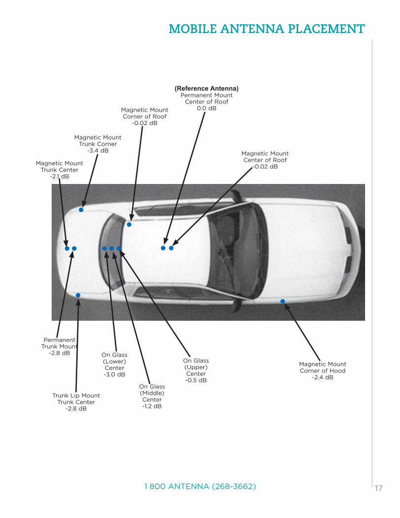
In terms of mounting mobile antennas on a vehicle, there are five general locations: roof, front fender, rear fender, trunk and rear window glass (although other glass mount locations may be used). Of these, the center of an automobile roof is considered the best for mobile antenna placement, followed by the center of the trunk lid, the fenders, then on-glass mounting. This ranking is determined by the amount of ground plane provided by the positioning and clearance from obstruction (i.e., the roof line). The center of the roof is considered the ideal mounting location, provided the roof is metal. The diagram below illustrates the effective loss (at 800MHz) due to insufficient symmetrical ground plane.
Larsen provides a complete selection of permanent and temporary mounting alternatives, using only the highest quality materials to ensure superior electrical performance and mechanical durability. They include magnetic mounts (MM, MS), trunk gutter brackets (TMB), mirror mount brackets (MB) and, of course, traditional permanent hole mounts for all antenna series.
MOBiLE AntEnnA PLACEMEnt
171 800 ANTENNA (268-3662)
MOBiLE AntEnnA PLACEMEnt
Magnetic MountTrunk Corner
-3.4 dB
●●
●
●●
●●● ●●●
Magnetic MountCorner of Hood
-2.4 dB
Magnetic MountCorner of Roof
-0.02 dB
Magnetic MountCenter of Roof
-0.02 dB
(Reference Antenna)Permanent Mount
Center of Roof0.0 dB
Trunk Lip MountTrunk Center
-2.8 dB
On Glass (Lower)Center-3.0 dB
PermanentTrunk Mount
-2.8 dB
Magnetic MountTrunk Center
-2.1 dB
On Glass (Middle)Center-1.2 dB
On Glass (Upper)Center-0.5 dB
18 www.pulseelectronics.com/products/antennas
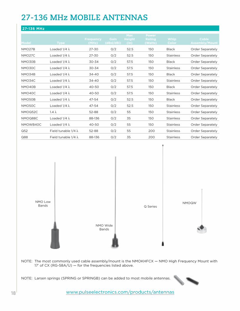
27-136 Mhz MOBiLE AntEnnAs
NOTE: The most commonly used cable assembly/mount is the NMOKHFCX — NMO High Frequency Mount with 17’ of CX (RG-58A/U) — for the frequencies listed above.
NOTE: Larsen springs (SPRING or SPRINGB) can be added to most mobile antennas.
NMOQWQ Series
NMO Wide Bands
NMO Low Bands
27-136 MHz
Max Power Frequency Gain Height Rating Whip CableModel Type (MHz) (dBd/dBi) (In) (Watts) Color Assembly/Mount
NMO27B Loaded 1/4 λ 27-30 0/2 52.5 150 Black Order Separately
NMO27C Loaded 1/4 λ 27-30 0/2 52.5 150 Stainless Order Separately
NMO30B Loaded 1/4 λ 30-34 0/2 57.5 150 Black Order Separately
NMO30C Loaded 1/4 λ 30-34 0/2 57.5 150 Stainless Order Separately
NMO34B Loaded 1/4 λ 34-40 0/2 57.5 150 Black Order Separately
NMO34C Loaded 1/4 λ 34-40 0/2 57.5 150 Stainless Order Separately
NMO40B Loaded 1/4 λ 40-50 0/2 57.5 150 Black Order Separately
NMO40C Loaded 1/4 λ 40-50 0/2 57.5 150 Stainless Order Separately
NMO50B Loaded 1/4 λ 47-54 0/2 52.5 150 Black Order Separately
NMO50C Loaded 1/4 λ 47-54 0/2 52.5 150 Stainless Order Separately
NMOQ52C 1.4 λ 52-88 0/2 55 150 Stainless Order Separately
NMOQ88C Loaded 1/4 λ 88-136 0/2 35 150 Stainless Order Separately
NMOWB40C Loaded 1/4 λ 40-50 0/2 55 150 Stainless Order Separately
Q52 Field tunable 1/4 λ 52-88 0/2 55 200 Stainless Order Separately
Q88 Field tunable 1/4 λ 88-136 0/2 35 200 Stainless Order Separately

191 800 ANTENNA (268-3662)
136-174 Mhz (VhF) AntEnnAsNMO MOUNTS
Max Power Frequency Gain Height Rating Whip CableModel Type (MHz) (dBd/dBi) (In) (Watts) Color Assembly/Mount
NMOWB150B Wideband 1/2 λ 135-174 0/2 51.75 100 Black Order Separately
NMOWB150C Wideband 1/2 λ 135-174 0/2 51.75 100 Stainless Order Separately
NMO150B 5/8 λ 144-174 3/5.2 51.5 200 Black Order Separately
NMO150C 5/8 λ 144-174 3/5.2 51.5 200 Stainless Order Separately
NMO150BHW 1/2 λ 144-174 0/2 51.5 200 Black Order Separately
NMOQW144 1/4 λ 144-152 0/2 21 200 Stainless Order Separately
NMOQW152 1/4 λ 152-162 0/2 21 200 Stainless Order Separately
NMOWBQB Wideband 1/4 λ 150-170 0/2 20 200 Black Order Separately
NMOWBQC Wideband 1/4 λ 150-170 0/2 20 200 Stainless Order Separately
NMOU150D Loaded 1/4 λ 150-165 0/2 18 200 Black Order Separately
NMOU155D Loaded 1/4 λ 155-170 0/2 18 200 Black Order Separately
NOTE: The most commonly used cable assembly/mount is the NMOKHFCX — NMO High Frequency Mount with 17’ of CX (RG-58A/U) — for the frequencies listed above.
GLASS MOUNT
Max Power Frequency Gain Height Rating WhipModel Type (MHz) (dBd/dBi) (In) (Watts) Color Cable Connector
KG144UDPL 1/2 λ 144-160 0/2 48 100 Black 14’ RG-58/U Dual Shield PL-259
KG160UD 1/2 λ 160-174 0/2 47 100 Black 14’ RG-58/U Dual Shield No Connector
KG160UDPL 1/2 λ 160-174 0/2 47 100 Black 14’ RG-58/U Dual Shield PL-259
LM MOUNT
Max Power Frequency Gain Height Rating Whip CableModel Type (MHz) (dBd/dBi) (In) (Watts) Color Assembly/Mount
LM150B 5/8 λ 144-174 3/5.14 51.75 200 Black Order Separately
LM150C 5/8 λ 144-174 3/5.14 51.75 200 Stainless Order Separately
LMWBQ Wideband 1/4 λ 150-170 0/2.14 18.5 200 Stainless Order Separately
LMWBQB Wideband 1/4 λ 150-170 0/2.14 18.5 200 Black Order Separately
KG Series Coil for LM Mount
NMO VHF Wide Band
Coil
NMO VHF 1/2 λ Coil
NMOQW Series NMOW-
BQ Series

20 www.pulseelectronics.com/products/antennas
136-174 Mhz (VhF) AntEnnAs
MISCELLANEOUS MOUNTS
Max Power Mount Frequency Gain Height Rating WhipModel Style Type (MHz) (dBd/dBi) (In) (Watts) Color Cable Connector
MHW150C PO/SO-239 1/2 λ 144-174 0/2 51.5 200 Stainless Order Separately
OM150CK Self-mounting 1/2 λ 144-174 0/2 51.75 200 Stainless 17’ RG-58A/U PL-259
PHW150C SO-239 1/2 λ 144-174 0/2 56.5 200 Stainless Order Separately
PO150B PO/SO-239 5/8 λ 144-174 3/5.2 51.5 200 Black Order Separately
PO150C PO/SO-239 5/8 λ 144-174 3/5.2 51.5 200 Stainless Order Separately
MSTFME Magnetic 1/4 λ 144-965 0/2 21 50 Black 12’ RG-174 FME Crimp
NOTE: The most commonly used cable assembly/mount is the NMOKHFCX — NMO High Frequency Mount with 17’ of CX (RG-58A/U) — for the frequencies listed above.
MSTFME
PHW Series Base Coil
MHW/PO Series Base
Coil
OM Series
A Successful Installation
A successful installation means that all product instructions are read, the right tools are available, and best practices applied. Below are a few tips to ensure your antenna performs as specified.
NMO Mounts: One way of ensuring proper grounding of your antenna system is to clear the paint on the underside of the mounting surface, such as the roof or trunk, with a medium grit sandpaper or other by other means. The NMO mounting hardware is designed to “cut” into the paint, however, paint thickness and total applied mounting torque may make conditions where grounding is insuf-ficient. The VSWR of the mounted antenna is the primary indicator that the ground is poor.
Glass Mounts: Glass mounts have very specific instructions for preparing the glass for an on-glass antenna and should be strictly followed. The most important instructions are to clean the glass avoiding ammonia-based cleaners, glass temperature must be close to room temperature (70 degrees), and after install, the whip should remain off and the mount dry for 24-72 hours. By preparing and installing correctly, you can rest assured knowing that your antenna is not going anywhere.
Tuning: Many users trust that the cutting charts provided with an antenna are absolute. It should be reinforced that cutting charts are guidelines. Ground plane size (a car versus a van), antenna mounting locations (the roof versus the trunk), and even mounting types (permanent roof mount versus magnetic mount versus trunk lip mounts) all have an impact in the tuning of an antenna. Using the cut chart with an economic SWR meter will help ensure the antenna is tuned correctly.

211 800 ANTENNA (268-3662)
220-225 Mhz AntEnnAs
NMO MOUNTS
Max Power Frequency Gain Height Rating Whip CableModel Type (MHz) (dBd/dBi) (In) (Watts) Color Assembly/Mount
NMO220B 5/8 λ 220-225 3/5.2 30 200 Black Order Separately
NMO220C 5/8 λ 220-225 3/5.2 30 200 Stainless Order Separately
NMO220CHW 1/2 λ 220-225 0/2 30 200 Stainless Order Separately
NMO220 Series
Appearance. Performance. Dependability. Long-term service. Those are key words describing Larsen 220 MHz mobile antennas. Larsen offers 220 MHz antennas in 1/2 wave and 5/8 wave designs for coverage
in the 220 MHz to 225 MHz band.
High-performance Larsen 220 MHz antennas are available in the NMO Premium Motorola-style 3/4” hole mount version.
Count on Larsen 220 MHz antennas to deliver these superior performance advantages:• Handles a full 200 Watts of power • VSWR at 1.5:1 or less• Heavy-duty base coils are air wound for lowest RF loss• Available with black or stainless whips• Optional shock spring internally shorted with highly flexible insulated wire to eliminate distortion• Durable MakroBlend® shells are UV and chemical resistant
NOTE: The most commonly used cable assembly/mount is the NMOKHFCX — NMO High Frequency Mount with 17’ of CX (RG-58A/U) — for the frequencies listed above.

22 www.pulseelectronics.com/products/antennas
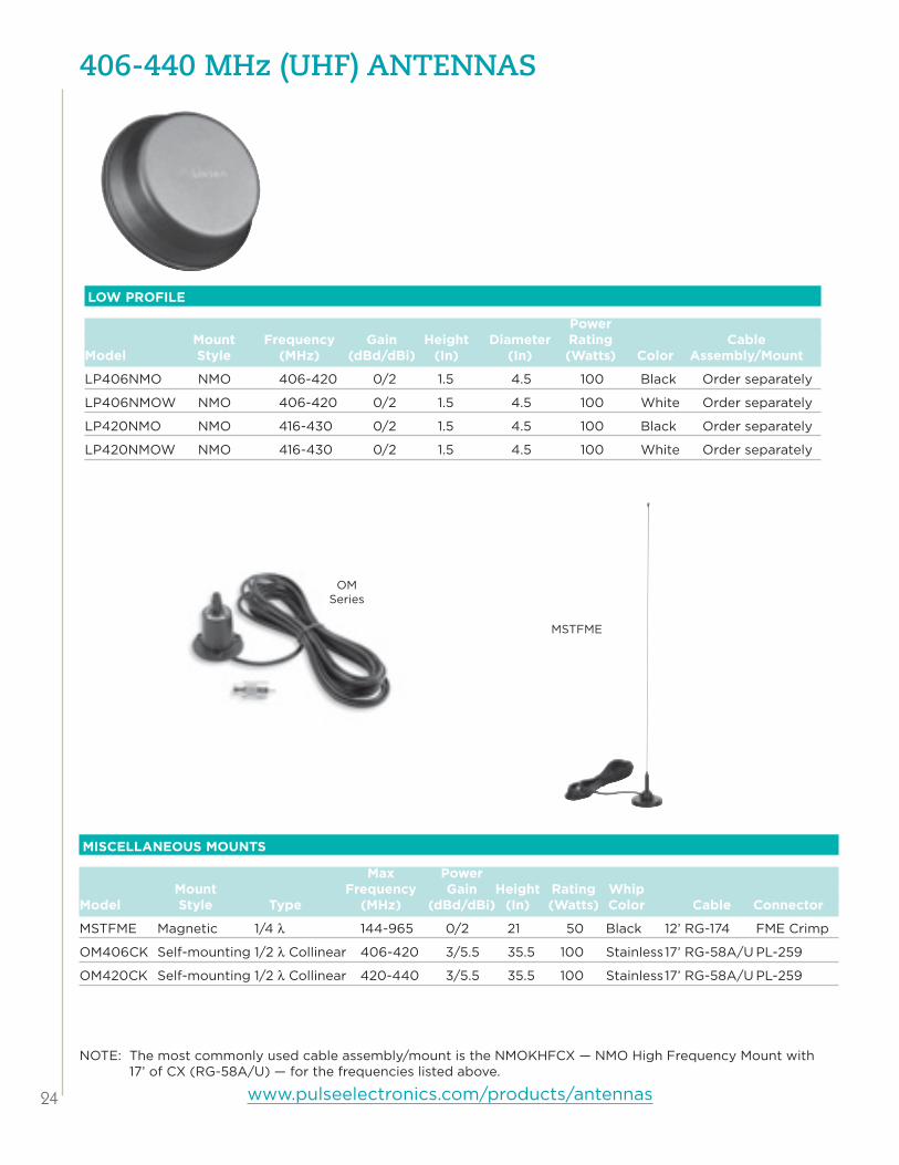
406-440 Mhz (uhF) AntEnnAs
NOTE: The most commonly used cable assembly/mount is the NMOKHFCX — NMO High Frequency Mount with 17’ of CX (RG-58A/U) — for the frequencies listed above.
NMO MOUNTS
Max Power Frequency Gain Height Rating Whip CableModel Type (MHz) (dBd/dBi) (In) (Watts) Color Assembly/Mount
NMO406C 5/8 Over 1/2 λ 406-420 3.4/5.6 33 200 Stainless Order Separately
NMO406CHW 1/2 λ Collinear 406-420 5.5/7.6 35.5 100 Stainless Order Separately
NMO4063CS 5/8 λ 406-430 3/5.2 19 200 Stainless Order Separately
NMOWB406C Wide Band 406-430 3.5/5.5 35.5 200 Stainless Order Separately
NMOQW406 1/4 λ 406-430 0/2 7 200 Stainless Order Separately
NMO420C 5/8 Over 1/2 λ 420-440 3.4/5.6 33 200 Stainless Order Separately
NMO420CHW 1/2 λ Collinear 420-440 5.5/7.6 35.5 100 Stainless Order Separately
NMO4303CS 5/8 λ 430-450 3/5.2 19 200 Stainless Order Separately
NMOWB430C Wide Band 430-455 3.5/5.5 35.5 200 Stainless Order Separately
NMO440C 5/8 Over 1/2 440-460 3.4/5.6 33 200 Stainless Order Separately
NMO440CHW 1/2 λ Collinear 440-460 5.5/7.6 35.5 100 Stainless Order Separately
NMOQW
NMO CS Series
NMOWB Series
NMO HW Series
NMO400 Series

231 800 ANTENNA (268-3662)
406-440 Mhz (uhF) AntEnnAs
GLASS MOUNT
Max Power Frequency Gain Height Rating WhipModel Type (MHz) (dBd/dBi) (In) (Watts) Color Cable Connector
KG406UDPL 1/2 λ 406-240 0/2 15 100 Black 14’ RG-58/U Dual Shield PL-259T
KG420UDPL 1/2 λ 420-440 0/2 15 100 Black 14’ RG-58/U Dual Shield PL-259T
LM MOUNT
Max Power Frequency Gain Height Rating Whip CableModel Type (MHz) (dBd/dBi) (In) (Watts) Color Assembly/Mount
LM406C 5/8 over 1/2 λ 406-420 3.5/5.6 33 200 Stainless Order Separately
LM420C 5/8 over 1/2 λ 420-440 3.5/5.6 33 200 Stainless Order Separately
LM440C 5/8 over 1/2 λ 440-460 3.5/5.6 33 200 Stainless Order Separately
KG Series
Coil for LM Mount
NOTE: The most commonly used cable assembly/mount is the NMOKHFCX — NMO High Frequency Mount with 17’ of CX (RG-58A/U) — for the frequencies listed above.
24 www.pulseelectronics.com/products/antennas
406-440 Mhz (uhF) AntEnnAs
LOW PROFILE
Power Mount Frequency Gain Height Diameter Rating CableModel Style (MHz) (dBd/dBi) (In) (In) (Watts) Color Assembly/Mount
LP406NMO NMO 406-420 0/2 1.5 4.5 100 Black Order separately
LP406NMOW NMO 406-420 0/2 1.5 4.5 100 White Order separately
LP420NMO NMO 416-430 0/2 1.5 4.5 100 Black Order separately
LP420NMOW NMO 416-430 0/2 1.5 4.5 100 White Order separately
NOTE: The most commonly used cable assembly/mount is the NMOKHFCX — NMO High Frequency Mount with 17’ of CX (RG-58A/U) — for the frequencies listed above.
MISCELLANEOUS MOUNTS
Max Power Mount Frequency Gain Height Rating WhipModel Style Type (MHz) (dBd/dBi) (In) (Watts) Color Cable Connector
MSTFME Magnetic 1/4 λ 144-965 0/2 21 50 Black 12’ RG-174 FME Crimp
OM406CK Self-mounting 1/2 λ Collinear 406-420 3/5.5 35.5 100 Stainless 17’ RG-58A/U PL-259
OM420CK Self-mounting 1/2 λ Collinear 420-440 3/5.5 35.5 100 Stainless 17’ RG-58A/U PL-259
MSTFME
OM Series

251 800 ANTENNA (268-3662)
VhF/uhF MuLtiBAnd AntEnnAsNMO MOUNTS
Max Power Frequency Gain Height Rating Whip CableModel Type (MHz) (dBd/dBi) (In) (Watts) Color Assembly/Mount
Center Loaded 1/2 λ/ 144-148/ 1.6/3.8NMO2/70B Collinear 440-450 3/5.2 34.75 100 Black Order Separately
Center Loaded 1/4 λ/ 144-148/ 0/2NMO2/70SH Center Loaded 1/2 λ 440-450 4/2 19 200 Stainless Order Separately
Center Loaded 1/2 λ/ 150-154/ 1.6/3.8NMO150/450C Collinear 450-460 3/5.2 37.75 100 Stainless Order Separately
150-165/ 0/2 450-470 0/2NMO150/450/800 Tri Band 806-960 0/2 16.5 100 Black Order Separately
GLASS MOUNT
Max Power Frequency Gain Height Rating WhipModel Type (MHz) (dBd/dBi) (In) (Watts) Color Cable Connector
1/2 λ/ 144-148/ 0/2KG2/70CXPL Collinear 442-448 2/4.2 32.75 100 Black 14’ RG-58A/U PL-259
1/2 λ/ 144-148/ 0/2KG2/70CXFME Collinear 442-448 2/4.2 32.75 100 Black 14’ RG-58A/U FME
KG2/70
NMO150/450/800NMO150/450NMO2/70
NOTE: The most commonly used cable assembly/mount is the NMOKHFCX — NMO High Frequency Mount with 17’ of CX (RG-58A/U) — for the frequencies listed above.

26 www.pulseelectronics.com/products/antennas
tunABLE 1/4 WAVE (136-152 Mhz) AntEnnAs
Tunable 1/4 Waves
Max Power Mount Frequency Gain Height Rating WhipModel Style (MHz) (dBd/dBi) (In) (Watts) Color Cable Connector
NMOQB NMO 136-512 0/2 23 200 Black Order Separately Order Separately
NMOQC NMO 136-512 0/2 23 200 Stainless Order Separately Order Separately
PQ PO/SO-239 136-512 0/2 22 200 Stainless Order Separately Order Separately
QB LM 136-512 0/2 22 200 Black Order Separately Order Separately
Q LM 136-512 0/2 22 200 Stainless Order Separately Order Separately
NMOQSPECB NMO 136-960 0/2 22 200 Black Order Separately Order Separately
NMOQSPEC NMO 136-960 0/2 22 200 Stainless Order Separately Order Separately
MSTFME Magnetic 144-965 0/2 21 50 Black 12’ RG-174 FME Crimp
MSTFME
NMOQ SPECQ/QB
NMOQC/NMOQB
PQ
NOTE: The most commonly used cable assembly/mount is the NMOKHFCX — NMO High Frequency Mount with 17’ of CX (RG-58A/U) — for the frequencies listed above.

271 800 ANTENNA (268-3662)
COAxiAL CABLE
Premium quality coax for applications from low-band to 6 GHz
RG-58 A/U, StrandedLarsen Part Number: CXCOAX
This cable serves well as a high-quality, low-cost coax for most applications below 512 MHz. Typical loss figures (per 100’ of cable) are 6.8 dBd at 150 MHz and 12.9 dBd at 450 MHz. Due to it’s relatively high loss at higher UHF frequencies (18.3 dBd per 100’ at 825 MHz), it is not usually recommended for use above 512 MHz. The stranded center conductor offers very good flexibility and long life under most conditions. Jacket material: Black PVC. Insulator material: Solid Polyethylene.
RG-58 A/U Dual Shield, StrandedLarsen Part Number: DSCOAX
RG-58 A/U coax employs two shields consisting of a full aluminum/mylar wrap covered by a braid. This combina-tion of shields, plus low-loss dielectric material and strand-ed center conductor makes an excellent choice for mobile applications. It has the right combination of low-loss (12.6 dBd per 100’ at 825 MHz), excellent flexibility and uses standard connectors. Jacket material: Black PVC. Insula-tor material: Foam Polyethylene. Larsen products using this coax are identified by “DS” in the part number.
RG-58/U Dual Shield, SolidLarsen Part Number: UDCOAX
This is Larsen’s premium coax for 800 and 900 MHz applications. The solid center conductor (20 AWG) is easy to use with all connectors. Digital applications in particular benefit from the 100% Duofoil aluminum shield. The shield is not glued to the dielectric making it easier to peel back for connector installation. The braid is 95% coverage. Jacket material: Black PVC. Insulator materi-al: Polyethylene. This cable is standard for most mount-ing kits used for 800 MHz and can be special ordered for use with other frequencies. Larsen products using this coax are identified by “UD” in the part number.
RG-213, StrandedLarsen Part Number: RG213
This RG-8-size coax uses a stranded center conductor, polyethylene dielectric and non-contaminating black PVC jacket making it ideal for outdoor applications where it will be exposed to ultraviolet light. Loss per 100’ is from 2.7 dBd at 150 MHz to 8 dBd at 900 MHz. Stranded
Center Conductor
Polyethylene Dielectric Braided
Conductor PVC Jacket
Stranded Center
ConductorPolyethylene
Dielectric Braided Conductor PVC Jacket
PVC Jacket
100% Shield
Stranded Center
ConductorPolyethylene
Dielectric Braided Conductor
100% Shield
Solid Center
Conductor
Polyethylene Dielectric Braided
Conductor
PVC Jacket

28 www.pulseelectronics.com/products/antennas
CABLE AssEMBLiEs
When it comes to installing antennas, installers face new challenges every day. Automobile manufacturers create sleek new designs with curved surfaces utilizing less and less metal. In addition, people are less
willing to drill a hole in expensive new cars. This creates problems when trying to install an antenna to achieve maximum performance.
Larsen, recognizing this issue, has developed a full line of permanent and temporary mounts to solve virtually every installation need. Each Larsen mount is manufactured of the highest quality materials, including premium coax.
Note: Connectors are shipped loose/uninstalled with all mounting kits except MMR magnetic mounts. An FME universal adapter is installed on all kits.
NMO 3/4” HIGH FREQUENCY MOUNTS
Model Coax ConnectorNMOKHFCX CX (RG-58A/U) No Connector
NMOKHFCXFME CX (RG-58A/U) FME Crimp
NMOKHFCXMPL CX (RG-58A/U) MINI UHF
NMOKHFCXPL CX (RG-58A/U) PL-259
NMOKHFUD UD (RG-58U Dual Shield) No Connector
NMOKHFUDFME UD (RG-58U Dual Shield) FME
NMOKHFUDMPL UD (RG-58U Dual Shield) MPL
NMOKHFUDSMA UD (RG-58U Dual Shield) SMA
NMOKHFUDTNC UD (RG-58U Dual Shield) TNC
NMOKHFUDPL UD (RG-58U Dual Shield) PL-259
Larsen NMOHF mounts are also available with DS (RG-58A/U Dual Shield) and LMR200 coax. For more information, please contact your local dealer.
NMOHF Thick MountHigh Frequency Configuration
NMOHF Thick MountLow Frequency Configuration
NMOHF MountHigh Frequency Configuration
NMOHF MountLow Frequency Configuration
nMOhF MOunts
All Larsen NMOHF (high frequency) mounts convert from low frequency applications to high frequency applica-tions and back by pulling or replacing the center pin and insulator.
NMOHF mounts require a 3/4” hole for mounting and include 17’ of coax unless otherwise indicated.
NMO 3/4” HIGH FREQUENCY THICk MOUNTS
Model Coax ConnectorNMOKHFCXTHK CX (RG-58A/U) No Connector
NMOKHFUDTHK UD (RG-58U Dual Shield) No Connector
NMOHFTHK (thick) mounts accommodates roof surfaces up to 1/2” thick.
Larsen NMOHF mounts are also available with DS (RG-58A/U Dual Shield) and LMR200 coax. For more information, please contact your local dealer.

291 800 ANTENNA (268-3662)
CABLE AssEMBLiEs
NMO HIGH FREQUENCY MAGNETIC MOUNTS
Model Coax ConnectorNMOMMRNOCONN CX (RG-58A/U) No Connector
NMOMMRFME CX (RG-58A/U) FME Crimp
NMOMMRMPL CX (RG-58A/U) MPL Crimp
NMOMMRN CX (RG-58A/U) N Crimp
NMOMMR CX (RG-58A/U) 58FCP
NMOMMRPL CX (RG-58A/U) PL-259
NMOMMRMPL CX (RG-58A/U) MPL Crimp
NMOMMRTNC CX (RG-58A/U) TNC Crimp
NMOMMRBNC CX (RG-58A/U) BNC Crimp
NMOHF magnetic mounts are 3.5” in diameter, have a pull strength of 80 pounds and include 12’ of coax.
Larsen NMOHF magnetic mounts are also available with DS (RG-58A/U Dual Shield) and LMR200 coax. For more informa-tion, please contact your local dealer.
NMOHF MIRROR MOUNTS
Model Coax ConnectorNMOKHFMBCX CX (RG-58A/U) No Connector
NMOKFHMBUD UD (RG-58U Dual Shield) No Connector
nMOhF MOunts
All Larsen NMOHF (high frequency) mounts convert from low frequency applications to high frequency applica-tions and back by pulling or replacing the center pin and insulator.
NMOHF mounts require a 3/4” hole for mounting and include 17’ of coax unless otherwise indicated.
30 www.pulseelectronics.com/products/antennas
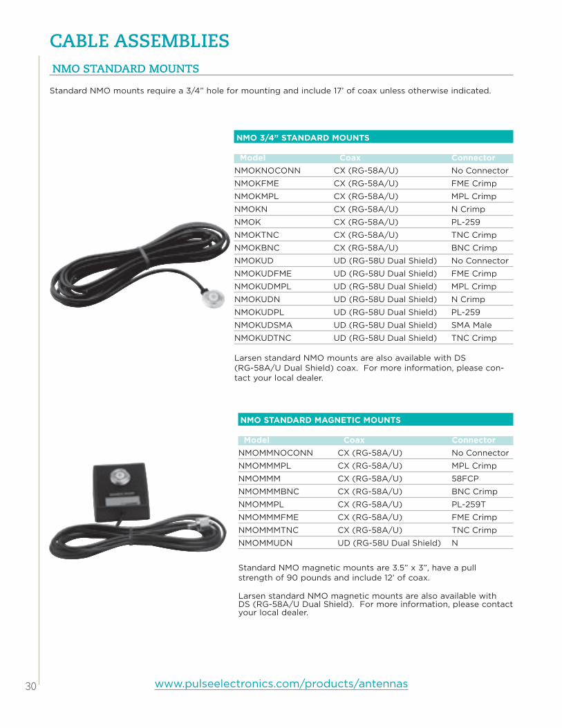
CABLE AssEMBLiEs
NMO STANDARD MAGNETIC MOUNTS
Model Coax ConnectorNMOMMNOCONN CX (RG-58A/U) No Connector
NMOMMMPL CX (RG-58A/U) MPL Crimp
NMOMMM CX (RG-58A/U) 58FCP
NMOMMMBNC CX (RG-58A/U) BNC Crimp
NMOMMPL CX (RG-58A/U) PL-259T
NMOMMMFME CX (RG-58A/U) FME Crimp
NMOMMMTNC CX (RG-58A/U) TNC Crimp
NMOMMUDN UD (RG-58U Dual Shield) N
Standard NMO magnetic mounts are 3.5” x 3”, have a pull strength of 90 pounds and include 12’ of coax.
Larsen standard NMO magnetic mounts are also available with DS (RG-58A/U Dual Shield). For more information, please contact your local dealer.
nMO stAndArd MOunts
Standard NMO mounts require a 3/4” hole for mounting and include 17’ of coax unless otherwise indicated.
NMO 3/4” STANDARD MOUNTS
Model Coax ConnectorNMOKNOCONN CX (RG-58A/U) No Connector
NMOKFME CX (RG-58A/U) FME Crimp
NMOKMPL CX (RG-58A/U) MPL Crimp
NMOKN CX (RG-58A/U) N Crimp
NMOK CX (RG-58A/U) PL-259
NMOKTNC CX (RG-58A/U) TNC Crimp
NMOKBNC CX (RG-58A/U) BNC Crimp
NMOKUD UD (RG-58U Dual Shield) No Connector
NMOKUDFME UD (RG-58U Dual Shield) FME Crimp
NMOKUDMPL UD (RG-58U Dual Shield) MPL Crimp
NMOKUDN UD (RG-58U Dual Shield) N Crimp
NMOKUDPL UD (RG-58U Dual Shield) PL-259
NMOKUDSMA UD (RG-58U Dual Shield) SMA Male
NMOKUDTNC UD (RG-58U Dual Shield) TNC Crimp
Larsen standard NMO mounts are also available with DS (RG-58A/U Dual Shield) coax. For more information, please con-tact your local dealer.

311 800 ANTENNA (268-3662)
CABLE AssEMBLiEs
NMO 3/8” THICk MOUNTS
Model Coax ConnectorNMOKCX38THK CX (RG-58A/U) No Connector
NMOKUD38THK UD (RG-58U Dual Shield) No Connector
NMO 3/8” mounts require a 3/8” hole for mounting and include 17’ of coax. The NMO38THK mount is designed for mounting surfaces with a thickness of 0.15” to 0.22”.
NMO TRUNk LIP MOUNTS
Model Coax ConnectorNMOTLP CX (RG-58A/U) PL-259
NMOTLPFME CX (RG-58A/U) FME Crimp
NMOTLPMPL CX (RG-58A/U) MPL Crimp
The NMOTLP mount is a Motorola style trunk lid mount, 2.5” x 2” with 17’ of coax.
NMO TRUNk GUTTER MOUNTS
Model Coax Color ConnectorNMOTMB CX (RG-58A/U) Stainless PL-259
The NMOTMB Motorola style trunk gutter bracket is 1.75” x 1.75” with 17’ of coax.
nMO stAndArd MOunts
Standard NMO mounts require a 3/4” hole for mounting and include 17’ of coax unless otherwise indicated.

32 www.pulseelectronics.com/products/antennas
CABLE AssEMBLiEs
LM MAGNETIC MOUNTS
Model Coax Connector
LMMMFME CX (RG-58A/U) FME Crimp
LMMMMPL CX (RG-58A/U) MPL Crimp
LMMM CX (RG-58A/U) 58FCP
LMMMTNC CX (RG-58A/U) TNC Crimp
LMMMBNC CX (RG-58A/U) BNC Crimp
LMMMPL CX (RG-58A/U) PL-259
LM magnetic mounts are 5/16” x 24 THDS roof mount, 3.5” x 3” with a pull strength of 50 pounds and include 12’ of coax.
Larsen LM magnetic mounts are also available with DS (RG-58A/U Dual Shield) coax. For more information, please contact your local dealer.
LM 3/4” MOUNTS
Model Coax Connector
LMKNOCONN CX (RG-58A/U) No Connector
LMKFME CX (RG-58A/U) FME Crimp
LMKMPL CX (RG-58A/U) MPL Crimp
LMKN CX (RG-58A/U) N Crimp
LMK CX (RG-58A/U) PL-259
LMKTNC CX (RG-58A/U) TNC Crimp
LMKUD UD (RG-58U Dual Shield) No Conn
LMUDFME UD (RG-58U Dual Shield) FME Crimp
LMKUDMPL UD (RG-58U Dual Shield) MPL Crimp
LMKUDN UD (RG-58U Dual Shield) N Crimp
LMKUDTNC UD (RG-58U Dual Shield) TNC Crimp
LM mounts are 5/16” x 24 THDS roof mount requiring a 3/4” hole.
Larsen LM mounts are also available with DS (RG-58A/U Dual Shield) coax. For more information, please contact your local dealer.
LM MOunts
All Larsen LM cable assemblies include 17’ of coax unless otherwise indicated.
LM TRUNk LIP MOUNTS
Model Coax Connector
LMTLP CX (RG-58A/U) PL-259
The LMTLP mount is 5/16” x 24 THDS trunk lid mount, 2.5” x 2”.
Larsen LMTLP mounts are also available with DS (RG-58A/U Dual Shield) coax. For more information, please contact your local dealer.
LM TRUNk GUTTER MOUNTS
Model Coax Connector
LMTMB CX (RG-58A/U) PL-259
The LMTMB trunk gutter bracket is 1.75” x 1.75” and comes with a LMK cable assembly.

331 800 ANTENNA (268-3662)
CABLE AssEMBLiEsPO MOunts
PO 3/4” MOUNTS
Model Coax ConnectorPOKNOCONN CX (RG-58A/U) No Connector
POK CX (RG-58A/U) PL-259
PO mounts are an SO-239 female type roof mount requiring a 3/4” hole and includes 17’ of coax.
PO MAGNETIC MOUNTS
Model Coax ConnectorPOMMM CX (RG-58A/U) 58FCP
The PO magnetic mount is an SO-293 female type, 3.5” x 3” with a pull strength of 50 pounds and includes 12’ of coax.

34 www.pulseelectronics.com/products/antennas
SMALL BAsE stAtiOn AntEnnAs
The following antennas have a VSWR of 1.5:1, power rating of 200 Watts and a UHF Female feed connection.
BSA SERIES
Frequency Gain LengthModel Type (MHz) (dBd/dBi) VSWR (In)
BSA45C Base loaded 1/4 λ 45-50 0/2 1.5:1 51.75
BSA118B 5/8 λ 118-121 3/5.2 1.5:1 51.75
BSA132B 5/8 λ 131-135 3/5.2 1.5:1 54.5
BSA150B 5/8 λ 144-174 3/5.2 1.5:1 51.75
BSA150C 5/8 λ 144-174 3/5.2 1.5:1 51.75
BSA220C 5/8 λ 220-225 3/5.2 1.5:1 33.75
BSA Series
BSA45C
351 800 ANTENNA (268-3662)
SMALL BAsE stAtiOn AntEnnAs
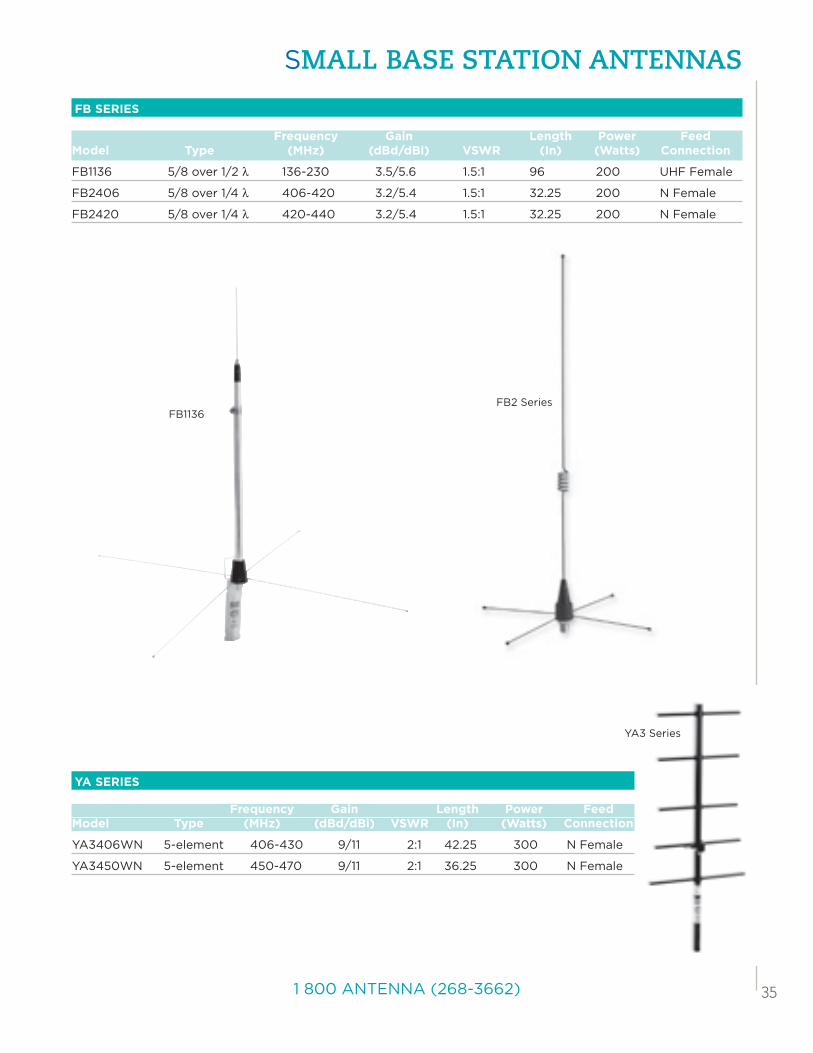
YA SERIES
Frequency Gain Length Power FeedModel Type (MHz) (dBd/dBi) VSWR (In) (Watts) Connection
YA3406WN 5-element 406-430 9/11 2:1 42.25 300 N Female
YA3450WN 5-element 450-470 9/11 2:1 36.25 300 N Female
FB SERIES
Frequency Gain Length Power FeedModel Type (MHz) (dBd/dBi) VSWR (In) (Watts) Connection
FB1136 5/8 over 1/2 λ 136-230 3.5/5.6 1.5:1 96 200 UHF Female
FB2406 5/8 over 1/4 λ 406-420 3.2/5.4 1.5:1 32.25 200 N Female
FB2420 5/8 over 1/4 λ 420-440 3.2/5.4 1.5:1 32.25 200 N Female
FB2 SeriesFB1136
YA3 Series
36 www.pulseelectronics.com/products/antennas
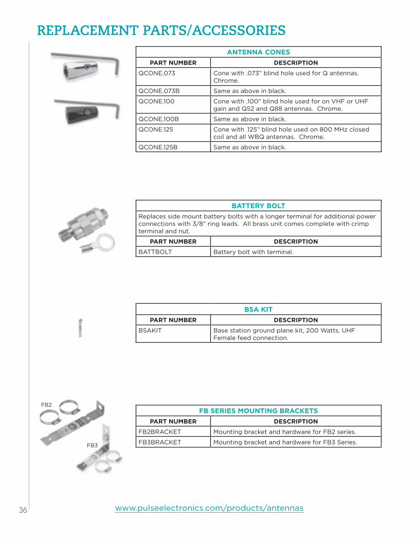
rEPLACEMEnt PArts/ACCEssOriEsANTENNA CONES
PART NUMBER DESCRIPTION
QCONE.073 Cone with .073” blind hole used for Q antennas. Chrome.
QCONE.073B Same as above in black.
QCONE.100 Cone with .100” blind hole used for on VHF or UHF gain and Q52 and Q88 antennas. Chrome.
QCONE.100B Same as above in black.
QCONE.125 Cone with .125” blind hole used on 800 MHz closed coil and all WBQ antennas. Chrome.
QCONE.125B Same as above in black.
BATTERY BOLTReplaces side mount battery bolts with a longer terminal for additional power connections with 3/8” ring leads. All brass unit comes complete with crimp terminal and nut.
PART NUMBER DESCRIPTION
BATTBOLT Battery bolt with terminal.
BSA kITPART NUMBER DESCRIPTION
BSAKIT Base station ground plane kit, 200 Watts, UHF Female feed connection.
FB SERIES MOUNTING BRACkETSPART NUMBER DESCRIPTION
FB2BRACKET Mounting bracket and hardware for FB2 series.
FB3BRACKET Mounting bracket and hardware for FB3 Series.FB3
FB2

371 800 ANTENNA (268-3662)
rEPLACEMEnt PArts/ACCEssOriEsGASkETS
PART NUMBER DESCRIPTION
RGNMOANT Rubber gasket internal to NMO coils, 3 per pkg.
RGOMANT Rubber gasket for OM series coils, 3 per pkg.
RGFB1ANT Rubber gasket for FB1 series, 1 per pkg.
RGPOMNT Rubber gasket for PO series coils, 3 per pkg.
RGSBKMNT Rubber gasket for SBK mounts, 3 per pkg
RGSS Rubber SuperSeal gasket for MakroBlend coils/bases, 3 per pkg.
GROMMETS AND HOLE PLUGSPART NUMBER DESCRIPTION
GROMMETS Plastic grommet locks securely into a 3/4” hole and grips the coax to hold it in the center. 100 per pkg.
HP34 Plastic hole plug for 3/4” hole when antenna is removed but not replaced. 5 per pkg.
HP38 Plastic hole plug for 3/8” hole when antenna is removed but not replaced. 6 per pkg.
Grommets
Hole Plugs
HOLE SAWPART NUMBER DESCRIPTION
HS1 Designed specifically for installing permanent mount mobile antennas. Makes a 3/4” hole and limits hole depth to 1/8”. Fits 3/8” or larger electric drill. Includes 2 blades.
HSBLADE Replacement blades for HS1, 2 per pkg.
kG REINSTALL kITSPART NUMBER DESCRIPTION
KGREINSTALL KG glass mount reinstall kit with die cut tape.
kG SWIVEL MOUNTSPART NUMBER DESCRIPTION
KGSWIVEL.073 KG swivel mount assembly, .073 diameter.
KGSWIVEL.100 KG swivel mount assembly, .100 diameter.
Hole Saw
HS Blade

38 www.pulseelectronics.com/products/antennas
rEPLACEMEnt PArts/ACCEssOriEs
RAIN CAPSPART NUMBER DESCRIPTION
LMCAPB Rain cap for LM mount.
NMOCAPB Rain cap for NMO mount.
NMO MOUNT ADAPTERPART NUMBER DESCRIPTION
A4 BSA/BA/SO-239 to NMO mount adapter
O-RINGSPART NUMBER DESCRIPTION
OLMNT O-Ring for LM mounting hardware, 3 per pkg
ONMOMNT O-Ring for NMO mounting hardware, 3 per pkg
ONMOANT O-Ring for NMO coils and bases, 3 per pkg
OPOMNT O-Ring for PO mounting hardware, 3 per pkg
MOUNT BRACkETSPART NUMBER DESCRIPTION
TMB34 Stainless steel trunk gutter bracket, 3/4” diameter hole. Screws included.
TMB38B Same as above in black.
TMB38 Stainless steel trunk gutter bracket, 3/8” diameter hole. Screws included.
TMB38B Same as above in black.
TMB58 Stainless steel trunk gutter bracket, 5/8” diameter hole. Screws included.
TMB58B Same as above in black.
TMB34D Fender bracket only. Fits Dodge Ram trucks year 2002 and older.
TMBOM Stainless steel trunk gutter bracket for OM antennas, screws included
TMB
TMBOM
TMB34D

ROD TIPSPART NUMBER DESCRIPTION
BALL1B Black rod tip for W490, W540 tapered rods. 10 per pkg.
BALL2B Black rod tip for Q and NMOQ antennas. 10 per pkg.
BALL3B Black rod tip for .100 diameter non-tapered rods. 10 per pkg.
SPRINGPART NUMBER DESCRIPTION
SPRING Chrome shock spring for Larsen VHF and UHF anten-nas.
SPRINGB Black shock spring for Larsen VHF and UHF antennas.
TEST MOUNT ADAPTERPART NUMBER DESCRIPTION
NMOTEST1 Test adaptor for NMO mount allows checking of coax feeding by allowing dummy load to replace the antenna. Also used to extend coax line to temporarily remote an antenna. Features floating contact design, good SWR match into 800 MHz range and nickel-plated brass construction.
SET SCREWSPART NUMBER DESCRIPTION
#6-32 Allen head set screws used on NMOQSPEC. Bag of 25.
#8-32 Allen head set screws used on all coils. Bag of 25.
#10-32 Allen head set screws used on all TLP mounts. Bag of 25.
SPANNER WRENCHPART NUMBER DESCRIPTION
SPANNER Spanner wrench for PO and NMO mounts
1 800 ANTENNA (268-3662)

LC238.B (08/13)
To order Larsen Amateur antennas, please contact your local dealer or:
Amateur Electronic Supply (AES)www.aesham.com
Milwaukee, WIPhone: 1-800-558-0411
Cleveland, OHPhone: 1-800-321-3594
Las Vegas, NVPhone: 1-800-634-6227
Orlando, FLPhone: 1-800-327-1917
Ham Radio Outlet (HRO)www.hamradio.com
Ham Radio Outlet (HRO)www.hamradio.com
Western US/CanadaTel: 1-800-854-6046
Mountain/CentralTel: 1-800-444-9476
SoutheastTel: 1-800-444-7927
Mid-AtlanticTel: 1-800-444-4799
New England/Eastern CanadaTel: 1-800-444-0047
NortheastTel: 1-800-644-4476