pulse width modulated control for led lighting - messiah · pulse width modulated control for led...
TRANSCRIPT

Final Report:
Pulse Width Modulated Control
for LED Lighting
May 10, 2004

Abstract Special effects lighting is an important part of the entertainment industry, and the
decreasing cost of electronics has increased the potential for lighting cont rol in both private and commercial applications. In addition, the advances in Light Emitting Diode (LED) technology and the continuing reduction in cost have made the use of LED light sources more affordable. Our project combines these two ideas, creating a lighting device with multicolor capabilities and interfacing this device with a personal computer for control purposes.
We designed a modular network of lighting fixtures operated by a personal computer. Through simple connections, any user can assemble a sophisticated lighting system in their house or business. From a personal computer connected to a local area network, the user can control lighting throughout an entire building, turning on and off fixtures and changing between millions of levels of color and brightness. Based on state-of-the-art technology, it’s a simple solution that can be used in almost any way you can imagine, from lighting your bedroom, to lighting a business, and even to lighting a stage.
Andrew Good, Neil Roberts, Jonathan Starr, and Brian Wohltmann have undertaken this project, under the advisement of Dr. David Gray and Professor Scott Weaver.

Table of Contents Acknowledgements
1 Introduction
1.1 Description
1.2 Literature Review
1.3 Solution
2 Design Process
2.1 Analysis and Experimental Work
2.2 Design Modifications
3 Implementation
3.1 Construction
3.2 Operation
4 Project Management
5 Budget
6 Conclusions
7 Recommendations for Future Work
References and Bibliography
Appendices

Acknowledgements
Dr. David Gray – Project Advisor – Dr. Gray provided guidance, advice, and encouragement for both the fall and spring semesters. He also suggested alternatives and new courses of action to overcome problems we encountered. Garden Spot Electric, Inc – Financial Sponsor – Garden Spot Electric provided the financial support necessary to complete this project as well as many gifts- in-kind. They also provided the use of their shop facilities for constructing the prototype. Scott Weaver – Network Communications Advisor – Professor Weaver provided information and support for the implementation of the Ethernet TCP/IP phase of our project. Dr. Don Pratt – Project Supervisor – Dr. Pratt supervised all senior projects and taught the Senior Project courses in the fall and spring. Matt Walsh – Electrical Laboratory Technician – Matt provided help with electronic circuit design and etching of the printed circuit boards.

1 INTRODUCTION 1.1 Description
Our team created a computer controlled lighting system using LED technology for use in various applications. One computer provides control over various lighting devices, with the ability to change color and brightness of each location independently. The LED has been chosen as our light source because of their increased power efficiency and longevity of usable life. By placing green, blue, and red LEDs in a single light fixture, a color spectrum of 16.7 million colors can be generated. A coprocessor using pulse width modulation, as shown in drawing PWM_8, controlled the colo r of each light. Varying the intensity of each LED coupled with a lighting fixture structure that blends the colors together created this vast array of colors.
The computer sends instructions specifying the intensity of each color that should be generated to the Ethernet control unit, which will translate the instructions and send them to each coprocessor using TTL RS232. The coprocessor will then send the desired pulse width modulated signal to the LEDs, creating the effect of colored light. CAT5 cable was chosen to send power to the lighting device, since multiple wires were necessary to send the red, green, and blue PWM signals. CAT5 is standard cable for computer networks, so that this system may be easily installed in any building already wired for network support.
The product was designed for modularity, so that components may be added to the system without difficult modifications. The potential for multiple control units to be connected in serial would allow for expansion in the capacity of the system. The PWM outputs were designed so that different lighting devices, with different power characteristics, can be connected. The following is a list of objectives that this project will meet:
1. Create a lighting device using LEDs such that the device can produce more ft-candles/watt of light per watt than a standard 60-watt bulb, or .902 ft-candles/watt.
2. Create a lighting device using LEDs such that the device can produce the color spectrum of 16.7 million colors.
3. Interface the lighting device to a power/data supply unit that can handle up to eight independently controlled LED fixtures.
4. The Ethernet control unit should be able to control light fixtures within a radius of 150 ft. 5. The power/data supply boxes should be able to communicate with each other through a
distance of 500 ft when connected in serial. 6. Provide a mechanism such that a failure of the computer will not turn the lighting device
off. Should the computer fail, the lights shall not lose power at any time.

1.2 Literature Review
The light emitting diode is becoming a more popular device in today’s ever-changing innovative technologies. It is making its mark in many different areas of lighting, from small battery operated devices to entertainment light shows and displays. The LED lighting device has the potential to become a key competitor in the home and industrial lighting industry, as well as areas of entertainment that rely heavily on specialty lighting. Recent advances in technology have led to the Luxeon Star, a LED manufactured by Lumileds, which is currently the brightest LED on the market. It has the same characteristics as the conventional LED, such as long life expectancy, low heat dissipation, and fast response time, but its light output power is unmatched with other LEDs (over 10 times as bright). These lights have a considerably low power consumption, which makes them beneficial in areas where energy conservation is appropriate and/or desired.
By using an array of red, green, and blue LEDs, millions of colors can be created by varying the light intensity of the three colored LEDs. This is achieved by using pulse width modulation (PWM), which varies the duty cycle of a square wave in order to control the brightness of the LED. A wave with a very short “on” time will appear dim to the human eye and a wave with a very long “on” time will appear to be as if the LED is on constantly, where in actuality, the LED is blinking at a rate that the human eye can not detect. This process of using PWM has the benefit of complete control of the color output of a light source as well as reducing power consumption since the LEDs are rarely in a constant “on” cycle. There are many devices that are capable of creating a PWM signal. Many microprocessors have dedicated PWM modes, and there are ICs that can be configured to create the signal as well.
An existing company that has recently been using PWM and LEDs for user controllable lighting is ColorKinetics, located in Boston, Mass. They have created a product line that is comparable to the objectives and goals of this project, but only market big industry companies. Their main goal is to provide special effect lighting for entertainment and industrial companies where large system setups will be used. The overall system that the company uses is composed of a controller, power supply and light fixture. The user works with the controller to achieve a desired color output effect. Data is then sent from the controller to the power supply, where data and power are sent to the light fixtures. The products and work that they have accomplished will become a benchmark for this project.
A second company that focuses on LEDs for lighting aspect is Advanced Illumination. This company also focuses on user controllable light sources, but does not have products where the RGB LED configuration is used to achieve the vast color spectrum. Their products are single colored and use another type of high power LED rather than the Luxeon Stars. However, their work and products will also help in our designs.
Very few of the technologies employed in our implementation of the communications are recent advances. Standard Ethernet communication will be used with the Cirrus Ethernet controller to give the board information to control the entire system. A processor splits the information into serial feeds with identifiers for each separate coprocessor, which sends signals to the lighting devices. This is very similar to designs by ColorKinetics or Advanced Illuminations. The way in which ours differs from existing systems is its modularity and centrally located control system. The standards data communications are in existence, but none of the systems we have encountered have implemented a central control system, so that it can function over a standard home or office network. All of the designs we encountered required a

single memory controller or similar device, with control over distinct lighting groups, to be plugged into a computer each time a lighting program change was desired.

1.3 Solution Design
The design was divided into four sections that may be constructed independently but communicate according to predefined guidelines. An overview of these sections is shown in drawing PWM_1. These sections include: PC control, Ethernet control, power/data supply (including coprocessors and LED drivers), and the LED fixture.
The first section of our project is the user interface, which is implemented in an application that allows central management of numerous lighting devices from a personal computer (PC). A user will cont rol the device using a graphical interface designed for a Windows Operating System. The Microsoft Windows operating system was chosen because of its widespread use throughout homes and businesses. The layout of the program is shown in drawing PWM_2 and the runtime operation is shown in drawing PWM_3.
The instructions from the computer are transferred through a network to the Ethernet control unit. We chose communication over an Ethernet network because of its widespread use. This decision stipulates that we must satisfy the Institute of Electrical and Electronics Engineers (IEEE) 802.3 Ethernet standard, as well as the Internet Engineering Task Force (IETF) RFC 791 and RFC 793 standards. The IEEE standard establishes protocols for both the computer and the Ethernet control unit to be connected to 10 Mbps Ethernet networks. The IETF standards describe Transmission Control Protocol/Internet Protocol (TCP/IP) data encapsulation and addressing techniques, and are consistent with Internet and network standards. These choices provide the capability for both the PC and the Ethernet control unit to be connected and communicate through an Ethernet network.
The Ethernet control unit will be composed of numerous components: Ethernet controller, ROM, and a FPGA. The Ethernet controller will receive commands from the computer over an Ethernet network. The ROM will support the Ethernet controller. The FPGA will allow our team to customize how the information is taken from the computer, and passed on to the lighting device. The FPGA may be programmed using the Very High Speed Integrated Circuits Hardware Definition Language (VHDL). The Ethernet control unit will then transmit the instructions over RS232 to the power/data supply unit. A flow chart describing the designed Ethernet control unit is shown in drawing PWM_4.
The power/data supply unit is comprised of a coprocessor and power supply circuitry. The coprocessor is an AWC PAK-Vc, which is designed to take commands from a RS232 interface and produce a pulse width modulated output. The pulse width modulated output is fed into a circuit of transistors, shown in drawing PWM_9, which draws the power from our power supply. This transistor circuitry provides the current necessary to light the LEDs, and mimic the signal that is being fed from the coprocessor. Changing the pulse width modulated signal then changes the intensity of the LEDs.
The lighting device consists of a fixture with 12 Lumileds Luxeon LEDs. The LEDs are arranged in an array with four of each color (red, green, and blue) connected in series, as shown in drawing PWM_10. Four of each color creates sufficient light output, and connecting each of these strings to a different output on the coprocessor allows for independent control. The structure of the lighting fixture was designed to provide optimal intensity, diffusion, and light mixing characteristics.

Alternatives The data could have been communicated over the Ethernet network using User Datagram
Protocol (UDP) rather than Transmission Control Protocol (TCP). UDP would have decreased the amount of overhead necessary for communication while decreasing the reliability of the network. In the event that packets of data are dropped from network, TCP will retransmit the packets to ensure delivery. UDP does not have this reliability feature, but would be simpler to implement in the circuitry and design of the Ethernet Control Box. Since the Ethernet Control Box was substituted with a manufactured part, TCP could be implemented with little difficulty.

2 DESIGN PROCESS 2.1 Analysis and Experimental Work
As the control program was written, various techniques were used to assess its functionality. The first section implemented was the ability of the program to maintain the state of each light in memory and change the value of the each light by accepting user input. Showing the current stored values of the lights in the edit boxes tested this aspect of the program. This is the same method that the program uses to show the user the current value of the lights.
The next implementation stage of the program was the network communication routines. It was necessary to ensure that the program updated the lights every time a change was made. The network communication aspect was tested by using packet sniffers, which capture every communication packet sent over the network and allows the user to view the data encapsulated in the packet. This method also ensured that the data was being sent in the proper byte order and that packets were sent upon every update.
During design and construction of the power/data supply unit, we needed a method of testing the functionality of our lights and control circuitry. Through the use of a computer program sent with our coprocessors we were able to use a simple program designed specifically for our coprocessors to control the output and thus the intensities of the LEDs. This program allowed us to test our theoretical responses of the system and determine if the transistor configurations were adequate, or if there could be a better way to implement the process.
Consistently throughout the process of designing and building we needed to troubleshoot errors. This consisted of checking for grounding problems, checking connections between components of the systems, using an oscilloscope to check for proper signal clarity, using multimeters to check voltages across components and current through others. Through troubleshooting we were able to find our errors and correct the problems we were facing.

2.2 Design Modifications The design of the circuitry for driving the LED lights changed numerous times throughout the design process. The original design used a NPN bipolar junction transistor as a switch that would have the series of connection of LEDs and a current limiting resistor between the supply voltage and the collector of the transistor. The base was connected to the PWM output pin of the coprocessor and the emitter was tied to ground. The problem with this design for our application was that the current limiting resistor for the LED was a low valued and high power resistor that generated too much heat. The main problem that this design had was its inability to drive the LEDs with a stable operating current. Small changes in the supplied voltage would result in different driving currents. Therefore, the length of the long transmission cables would have varying voltage losses that would result in the LEDs not receiving a stable driving current of 350mA. After looking for new ways of generating a stable current to the LED branch, we came up with a design that used a voltage regulator as a current source. The process of using a voltage regulator as a current source is fairly simple. All that is needed is to connect the proper valued resistor between the output and adjustment pin. This configuration resulted in a very stable driving current that was independent of the source voltage. The challenging part was finding a way to turn on and off the driver with the PWM signal. In order to do this, we used two transistors, where one would drive the other into saturation and allow the voltage source to connect to the input of the voltage regulator when the PWM signal went high. The complete circuit schematic can be found in the appendix. Using the voltage regulators as current sources allowed more flexibility in cable lengths, since voltage drops across lengthy lines became ineffective in operation as well as less power consumption making the device more efficient. Originally, a power over Ethernet configuration was suggested where the data and power would be sent to the lighting device through CAT5 cabling. The transistors configuration that connects the power supply, coprocessor output, and LEDs would then have been located in the fixture. The increased flexibility of the aforementioned transistor design allowed us to transmit the PWM signal over a cable of variable length, which made transmitting the data to the lighting device inefficient. All the circuitry is now located in the Power Supply/Data Control boxes, which creates a cleaner and more durable design.
The original design of the Network Connector involved putting everything on a single board, plugging it into the network and then running a wire to the processors that run the lights. We first had to learn a few things in order to know how to actually build the part. Printing out the manual for an Ethernet Controller and learning a language called VHDL in order to program our custom microprocessor allowed me to have a rough idea of what was going to happen. The first step required a signal in order to send information to the processors that run the lights. This meant another circuit would have to be designed to add on to the board. The code was written to create the microprocessor but we did not yet have the hardware to make it. After consulting with our advisor, Scott Weaver, we were able to obtain the parts for this from Penn State, where he studied VHDL as well. He was able to get an FPGA development board, which changed our design drastically. Instead of tacking it onto the same board, we had to create another board to stick into the development board as an addition. At this point, I had to start the actual design of the board. This involved several things; at the top of the list was how to tie the Ethernet to the microprocessor, which was a problem because the wires might cross over each other. Designing our own microprocessor means that I can assign a different pin to do a different thing, so we

were able to change the pins so that nothing crossed. The second problem was that only certain pins could accept a clock signal. This meant that parts of the board had to be redesigned to make up for this. The final problems were much easier; to create special variables for the Ethernet Controller and to make sure the Ethernet Controller is read properly by our custom microprocessor.

3 IMPLEMENTATION 3.1 Construction Computer Control Program
The computer control program implemented most of the functionality designed from the beginning. The completed program is shown in Figure 3-1 as well as in drawing PWM_2. The channel control pages (top middle and right) allow the user to control the individual RGB levels by either changing the value in edit boxes or by moving sliders. The edit boxes allow the user to set precise va lues, while the sliders give make the interface more graphic oriented and user friendly. The group selection page (top left) allows an increase in the number of lights that may be controlled independently and presents a way for the user to separate the lights into organizational groups. The cue control page (bottom) allows the user to save presets and reload them at a later time. The program allows a user to save presets to a file on a hard disk and open the file at a later time. Presets can also be programmed with instructions for advancing to another preset, with fade times that allow programmed color changes and strobe effects.
The program was created using Microsoft Visual C++ 6.0. A figure describing the operation of the program during runtime is shown in drawing PWM_3. Many of the classes shown are automatically constructed using Microsoft Foundation Class (MFC) libraries, although several of these classes needed to be modified. Eight classes were constructed to support the different functions of the program: CRoomSelection, CChannels, CColorControl, CCueControl, CNetworkSettings, CLightingDevice, CCue, and CCopSettings. CRoomSelection, CChannels, CColorControl, and CCueControl control the user input to change the intensity values of each light. CNetworkSettings and CCopSettings control user input to change the addressing functions of the coprocessor and the network. CLightingDevice and CCue handle the necessary data storage. The source code for the entire program has been included on a compact disc for future reference.
The design of the program changed when we realized that the Ethernet Control Box would not be completed on schedule. The Ethernet-to-RS232 converter communicated using Transmission Control Protocol (TCP). The program had to be changed to implement TCP rather than User Datagram Protocol (UDP). Originally the design implemented a way for the user to change the color of each light by selecting the color from a palette. This design feature was dropped because of the difficulty of imbedding a color palette onto a window. The MFC classes
Figure 3-1: The format of the control program has been separated into three functions for individual light control, organization of several lights into
groups, and stored presets.

are designed so that a dialog box with a color palette can be easily implemented, but opening a palette that stays active during the entire session is much more difficult.
Ethernet Control Unit
Before the design of the Ethernet Control Unit even began, there were several things that needed to be learned. First, in order for the FPGA to be programmed, VHDL must be learned. Since VHDL is by no means a simple language and the design we were implementing was complicated as well, this took a lot of study and communication with our advisor. The second element was learning how the Cirrus Logic CS8900A Ethernet controller worked. The manual Cirrus Logic provides is long and complicated and very little of it is important to our implementation. Much of the time spent simply figuring out what to study. After a few times through it, we were able to determine what we needed for our relatively simplistic use of the controller and the rest of the manual was crossed out or removed. This, along with the technical documents outlining example layouts similar to ours allowed us to finalize the design of the peripheral board.
One of the main initial hurdles encountered during the construction was that we could not use the school provided software to create the proper trace structure necessary for the complex peripheral board, shown in Figure 3-2. The board was then created entirely by user-drawn lines. In the end, this created a much better looking design than the software would have created even if it could have linked the traces properly, but expended a lot of time that the software could have helped us avoid. This also meant that during the trace creation, we could reorder the pins connecting to the FPGA in such a way that the traces could wrap cleanly around the board (which the software could not have done even under best circumstances). The reason we were able to do this is because the FPGA has programmable inputs, so that we can change the bit order to be reflected on different pins. The next problem was how to create an efficient clock input to be fed to the FPGA to create the RS-232. On initial thought, we were tempted to simply hook up a clock generator to the board. Instead, we used a 555 timer with associated electronics. This produced a fairly accurate clock signal, but because RS-232 needs a highly accurate clock signal, we replaced a resister with a potentiometer allowing us to vary the frequency created. Our first attempt at developing the board failed and several blotches were left on the board.
Figure 3-2: The traces for the Ethernet controller board contained extremely
small traces and had to be drawn individually using a computer.
Figure 3-3: The Ethernet controller board nears completion with the
components soldered into position.

After discussing this with Matt, the lab technician, it was decided that upon the next development, the stencils would be firmly attached to the glass tray with extra tape. This produced fantastic results and on careful watch of the etching, we were left with a near perfect board. Since the lines were so small, we had to do many repairs. This included both bridging small gaps in the traces and separating traces from each other. As this was being done upon completion, the board was electronically checked for bad traces. The first time we attempted to mount the Ethernet controller, it was slightly misaligned. This meant that the chip must be completely removed. After that was done, we used another one of the controllers we had obtained in our samples and made a successful solder. After the board was completed, we attempted to connect it to the development board holding our FPGA, shown in Figure 3-4, to test to see if the clock signal was output as expected. Unfortunately, we were unable to obtain any output and none of the chips were getting warm as expected. Upon disconnecting the peripheral board, we realized that the development board was not outputting the voltage expected from its 3.3V pin. Not only that, but the voltage regulators did not seem to be functioning at all. We took the board to Scott Weaver, who was advising us on the FPGA, and we ran through basic set up and attempted to program the board. He was unable to provide any feedback regarding these problems and emailed his contact at Penn State. When his teacher answered, he provided no feedback related to the specific problem we were having, only course documents and support websites.
In the weeks following, Scott Weaver was unable to give us any more help than he already had and he also was having trouble with his contact. We emailed and phoned his contact at Penn State several times and got nothing in return. Since time was running out and the development board was unlikely to work, we had to shift gears and put in a replacement.
Figure 3-4: The FPGA board (right) is attached to the Ethernet control board (left) to test its
capabilities.
Figure 3-5: A replacement had to be bought to perform the Ethernet control board and FPGA functions. The selected device is the Sena HelloDevice LS100 and performs the conversion from Ethernet to RS232 communication protocols.

Since early on, we had known that we could replace this board with an Ethernet to RS-232 converter. After evaluating several alternatives, we selected the Sena HelloDevice LS100 shown in Figure 3-5. This device performs the conversion from Ethernet to RS232 protocols.
Power/Data Supply Unit and Light Fixtures
Once the circuitry for the LED drives was finalized we could begin constructing the actual driver board shown in Figure 3-6. By using Ultiboard, we were able to design and create the necessary board with all of the components placed in a fairly simple layout. The size of the board is somewhat large, but we had no other size constraints than to get it inside of the 16”x 16” aluminum enclosure that would house all of the electronics. Taking careful steps in planning the layout of the driver board resulted in a successful first try of making the PCB. Soldering components was not trouble either because of the well spaced board. Once everything was soldered into place, the board was tested with low voltage in order to prevent any damage to critical components. Care was taken to check that each PWM output generated by the coprocessors was correct and that each current driver was outputting the correct value of current so that the LEDs would not be destroyed. After the driver board was working properly, we connected the LED fixtures with the CAT5 cable to see the driver working as we had hoped. The LEDs worked great and brightness levels were easily controlled with the PWM signals. Overall, a lot of time was used to make sure that everything looked and worked exactly as we wanted it to.
The PCBs were constructed using the Messiah College electronic laboratory. Although the etching equipment produced satisfactory results, some parts had to be patched to repair broken traces. Higher quality etching equipment would have created cleaner boards. In addition, the soldering of the surface mount components was completed in the lab, but more efficient equipment would have created a better product.
Figure 3-6: The LED driver board was designed using Ultiboard and is shown in a 3-D rendering (upper). The completed board (lower) receives a signal from the HelloDevice LS100 and creates a
PWM signal capable of controlling four independent lights.

Upon completion of the PCBs, we attached our heat sinks and completed the boards and made interconnections. Then we combined all control and power elements into our aluminum enclosure shown in Figure 3-7. To ensure that our devices remained cool, we added two cooling fans to the box, one pulled outside air in while the other removed the air from the devices. By using standard CAT5 connections to the outside of the box, we are able to simply add or remove lights.
Our light fixtures were constructed using enclosures from a tree lamp, as shown in Figure 3-8. Each fixture contained 12 LEDs: 4 red, 4 green, and 4 blue. These LEDs were mounted on a 1/4" aluminum plate. This plate aids in heat dissipation from the LEDs. The connections are made from the control box to the LEDs by a CAT5 cable. This cable supplies all the power and data necessary to control the fixture. To diffuse the light we used a stage lighting filter paper that provided the necessary diffusion.
Figure 3-7: All the power and data components are fixed into a protective casing.
Figure 3-8: Each lighting fixture contained twelve total LEDs: four red, four green, and four blue.
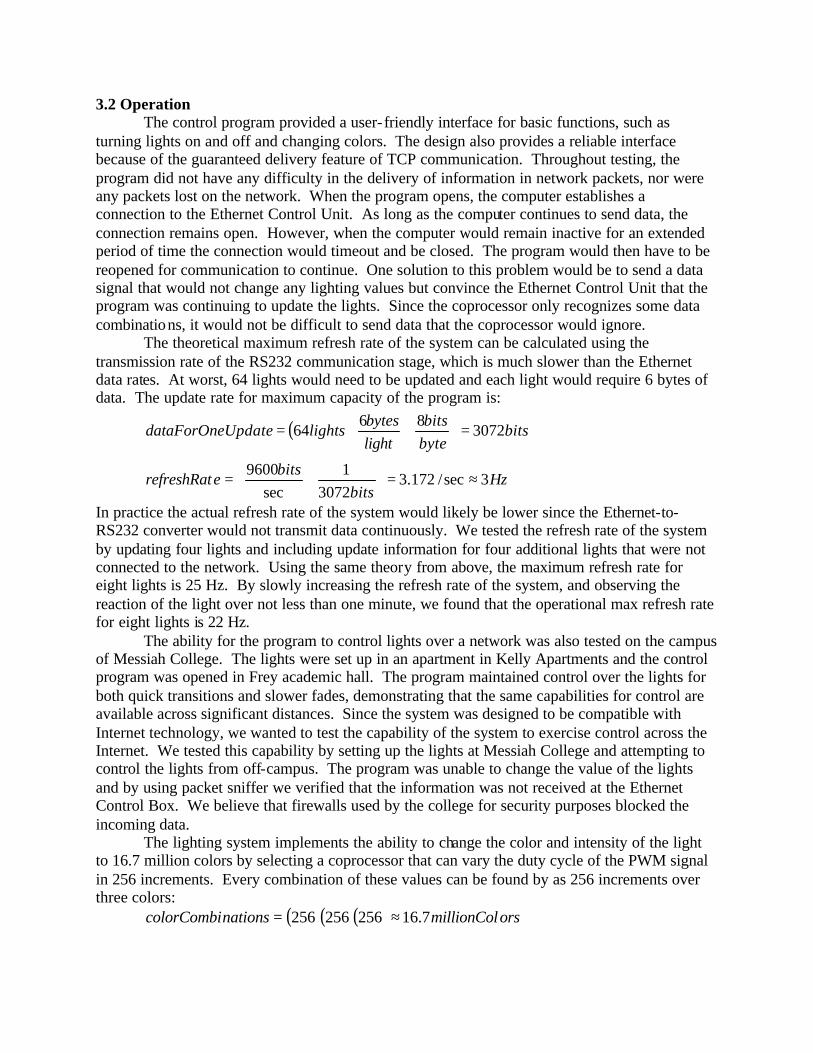
3.2 Operation The control program provided a user- friendly interface for basic functions, such as
turning lights on and off and changing colors. The design also provides a reliable interface because of the guaranteed delivery feature of TCP communication. Throughout testing, the program did not have any difficulty in the delivery of information in network packets, nor were any packets lost on the network. When the program opens, the computer establishes a connection to the Ethernet Control Unit. As long as the computer continues to send data, the connection remains open. However, when the computer would remain inactive for an extended period of time the connection would timeout and be closed. The program would then have to be reopened for communication to continue. One solution to this problem would be to send a data signal that would not change any lighting values but convince the Ethernet Control Unit that the program was continuing to update the lights. Since the coprocessor only recognizes some data combinations, it would not be difficult to send data that the coprocessor would ignore.
The theoretical maximum refresh rate of the system can be calculated using the transmission rate of the RS232 communication stage, which is much slower than the Ethernet data rates. At worst, 64 lights would need to be updated and each light would require 6 bytes of data. The update rate for maximum capacity of the program is:
( )
Hzbits
bitserefreshRat
bitsbytebits
lightbytes
lightsUpdatedataForOne
3sec/172.33072
1sec
9600
307286
64
≈=
=
=
=
In practice the actual refresh rate of the system would likely be lower since the Ethernet-to-RS232 converter would not transmit data continuously. We tested the refresh rate of the system by updating four lights and including update information for four additional lights that were not connected to the network. Using the same theory from above, the maximum refresh rate for eight lights is 25 Hz. By slowly increasing the refresh rate of the system, and observing the reaction of the light over not less than one minute, we found that the operational max refresh rate for eight lights is 22 Hz.
The ability for the program to control lights over a network was also tested on the campus of Messiah College. The lights were set up in an apartment in Kelly Apartments and the control program was opened in Frey academic hall. The program maintained control over the lights for both quick transitions and slower fades, demonstrating that the same capabilities for control are available across significant distances. Since the system was designed to be compatible with Internet technology, we wanted to test the capability of the system to exercise control across the Internet. We tested this capability by setting up the lights at Messiah College and attempting to control the lights from off-campus. The program was unable to change the value of the lights and by using packet sniffer we verified that the information was not received at the Ethernet Control Box. We believe that firewalls used by the college for security purposes blocked the incoming data.
The lighting system implements the ability to change the color and intensity of the light to 16.7 million colors by selecting a coprocessor that can vary the duty cycle of the PWM signal in 256 increments. Every combination of these values can be found by as 256 increments over three colors:
( )( )( ) orsmillionColnationscolorCombi 7.16256256256 ≈=

In order to test our lighting efficiency, we used a light meter that measured the light output in foot-candles. In order to determine the output, we turned a light on at full white and measured the output at a distance of 18" from the light meter. From our current configuration, we obtained 22.9 foot-candles (fc). Next we replaced our fixture with a standard 60-watt incandescent bulb. The incandescent bulb supplied 54.1 foot-candles at the same distance. By dividing the output of the device in foot-candles by the power used for supply of the light we obtained a measure of the foot-candles per watt of electricity used. Our fixture supplied 22.9 foot-candles using 23.77 Watts. This yields a fc to Watts ratio of .96 fc/W. A sixty-watt bulb supplies 54.1 fcs using 60 watts, which is a fc to watt ratio of .90 fc/W. Our fixture creates 6.84% more light per watt than a 60-watt bulb.

4 PROJECT MANAGEMENT For this project, our group was subdivided into two groups. Jon Starr and Neil Roberts
focused their time and efforts on the computer interface and Ethernet control of the project. Brian Wohltmann and Andrew Good focused on the LEDs, PWM, power supply, and wiring. Specific tasks were assigned to group members where specific skills and abilities aided in the accomplishments of the task. By having a good balance of computer and electronics knowledge within the group, equal amounts of technical and design work was delegated amongst the team. Other areas that deal with time management and communication was assigned to proper team members. Open communication within the team helped ensure that equal amounts of work were assigned to each member and that the progress remained on task.
There was one unexpected difficulty that hindered the progress of the overall project. The lack of development of the Ethernet control device until the end of the semester resulted in an alternative that would be substituted in order to keep the project on track. Miscommunication about the status of the Ethernet controller was the main cause of having to drop the development of our designed controller. Even though we hit a wall with the Ethernet controller not being completed, we were able to find a substitution and implement it in a fairly short amount of time. There were no other major difficulties that impeded the progress of the project. We were very pleased to see that what we envisioned at the beginning of the project was accomplished with few modifications to the overall design in the end.
An updated Gantt chart that outlines the amount of time used in order to complete tasks is
attached in the appendix of this report.

BUDGET Garden Spot Electric, Inc. was generous enough to allow us to have a budget of $1000. This covered the majority of our expenses. Our budget is shown on the following page. This budget shows a breakdown of costs into four main categories: Lighting Control, Lighting Fixture, Research and Development and Miscellaneous. Lighting Control The control aspect of our system cost $417 without the cost of our Gift in Kinds included. The total price for all the components involved in controlling our LED fixture totaled $551. Lighting Fixture The fixture included such components as the LEDs, enclosures, diffusing lens, and heat sinks. Our total cost for components involved in the fixture is $561. Including Gift in kinds, our cost would be $566. Research and Development All projects need to be researched. We needed two books. These books were bought by our team members for their personal libraries. The total cost came to $100. Miscellaneous There were many pieces involved with our project that either fit into multiple categories, or into categories that did not warrant their own breakdown. These costs totaled to $104 before $15 in gift- in-kind donations. Production Costs If our system were to be put into production the cost spent on each of these sections would be drastically reduced. The total cost would be $694. This cost includes one Power/Data supply box and one light fixture.

Cost Projected
Item To Us Received From Garden Spot Messiah College Other Production Cost Lighting Control Coprocessors $204.60 GSE $204.60 $74.85 FPGA GIK Penn State $12.00 FPGA Development Board GIK Penn State $50.00 Ethernet Controller GIK Cirrus Logic $2.00 PC Boards Messiah College Enclosure GIK GSE $60.00 $60.00 Heat Sinks GIK Messiah College Junk Bins $10.00 RS232 Converter $128.00 Messiah College $128.00 $128.00 Lighting Fixture LED's $521.75 GSE $521.75 $160.00 Power Supply $82.89 GSE $82.89 $220.00 Fixture Diffuser $22.43 GSE $22.43 $1.00 Light Fixtures $17.00 GSE $17.00 $6.00 Heat Sinks GIK GSE Scrap $5.00 Miscellaneous Cat5 Cable & Connectors GIK GSE $15.00 Misc Electronic Components $73.22 GSE & Messiah $73.22 $15.00 $24.00 EEPROM Programmer $31.02 Messiah College $31.02 Research & Development Visual C++ GIK Messiah College $400.00 Books Neil & Jon $100.00 Total $1,080.91 $921.89 $574.02 $234.00 $693.85 Grand Total $1,729.91

CONCLUSIONS Overall Success Through the course of our senior year we encountered much success, and yet faced many struggles as well. From the start of the fall semester we seemed to be on schedule. Much research was accomplished during the summer and we were prepared to work to accomplish our goals and objectives. By the time Christmas break rolled around we had accomplished the testing of the theory behind the control and power of the lights. As we returned from break we were ready to start working. In the fall we had ordered most of the parts for construction. This allowed us to begin preparing the prototype light. We did not, however, start construction on the controller until late February. This was partially due to a miscommunication and also a struggle to find a specific part. In the end we were able to complete two of the three main sections and find an alternative solution for the third. We were happy with our success, and in the end the majority of our objectives were met. Objective Completion 1) Efficiency: We wanted to make a light source that had the ability to be more efficient than a 60 watt incandescent bulb. Using a light meter we were able to measure our light output and determine the foot-candles provided by each source. Upon comparison our fixture had 6.84% greater efficiency in foot-candles/watt. 2) Color Spectrum: Through the use of our coprocessors which could create a PWM signal with an on time from 0 to 512 microseconds at a resolution of 2 microseconds, therefore creating 256 possible intensities for each color set of LEDs. The combination of these colors creates the 16.7 million colors we desired.
colorsmillion 777.16256256256 =××
3) PC Control Through a Network: Our computer program gave us the ability to control all of our light fixtures through a simple yet powerful interface. This program was also made to allow control throughout a network. This objective was tested successfully on the Messiah College Network. We were able to control lights set up in a Kelly apartment from a lab in Frey. 4) Control of Devices Through a Power/Data Supply Unit: This objective was not met. As we progressed into the project we realized that we were not going to be able to build the lights to be controlled due to financial constraints. This objective could be met by doubling the size of our control board. The coprocessors are currently able to handle the additional lights but the switching circuitry would need to be added. 5) Control Within 150 Feet: This objective was met by using a current source instead of the originally planned voltage regulation. The current source allowed a much greater length of communication by making the current constant through the circuit and allowing as much voltage drop as necessary.

6) Communication between Power/Data Supplies > 500 Feet: This objective was also not met, once again due to financial constraints. We were not able to build another box and the refore the objective became somewhat obsolete for prototyping purposes. It would, however, not be hard to implement. Essentially, we need to build a repeater to boost the power of the signal send on to the next control box. 7) Lights Remain on After Computer Failure: Our computer sends out a signal once, this signal is then converted to the proper protocol and received by the coprocessors. The signal from the coprocessor continues uninterrupted until it receives another signal. This allows our light to remain at the current state when the computer is turned off or the control program is shut down Lessons Learned This project has taught us many lessons. We were told from the beginning that we will run into problems. This advice was correct. We experienced everything from team conflicts over working and accomplishing tasks, lack of available parts, to simple grounding problems and the much larger problem of lack of communication.
The lack of communication was the biggest hurdle our group had to overcome. We separated our project into multiple sections. This made the group members specialize in areas they were working. If the other members did not understand one aspect of the project it was hard to determine who was on schedule. This caused us to feel as though we were ahead of the game when we were actually missing key components. We learned that communication is the most important issue in any project where multiple people are involved. Parts availability became an issue as we rushed to complete the project. Some components, necessary from day one, were not communicated in time to allow for finding and delivery of the parts. We know now that it is important to leave plenty of lead time for both ordering of parts and searching for the proper equipment. We found it very helpful to know as much information about the issue coming into the project. Through the summer we were fortunate enough to start gathering information. We were also lucky enough to work on a project that we were interested in. These factors helped us remain focused and kept us interested in working on the project to completion.

7 FUTURE WORK First, two of the original objectives were not met through the course of this project: the
ability to control eight lights from a single control box and the ability to connect multiple control boxes together. Both of these objectives would increase the number of lights that the system can handle.
Second, the color mixing of the light fixtures could be improved through a careful analysis of the optics of each light. Our design had some difficulty with the color of the light changing at the edges of the light beam, which created shadows of various colors. This aspect could be improved by designing the reflective surface of the light fixture and obtaining a better diffuser.
Third, the ability of the control program to save presets is quite cumbersome to use and requires the user to remember how each cue has been stored. An implementation that allowed the user to view all of the cues and the light values would make the program much more user friendly. The storing procedure could also be designed to allow the user to view a light show on a timeline graphic so that the transitions between cues can be seen easily.
Fourth, the control program should be thoroughly tested and the program errors eliminated. The session timeout problem described in the operation section of this report should also be eliminated.
Fifth, the original design was created as it was because we wanted the FPGA to be reprogrammed in the future to support new features. One of the amazing things about this piece of hardware, and the design that we had created around it, was that simply by reprogramming the FPGA, we could add an instruction set of any structure. What this means is that depending on how the information is sent to the box, the FPGA could be taught how to handle it and change the way it outputs. To take the project even further, a memory interface could easily be created to handle a robust light show system. This memory structure would have to be recreated on a new board, but could use the existing on board EEPROM which is being used by the Ethernet controller. Since the Ethernet controller needs very little information, everything else on the chip is open to be used. Obviously, one of the great examples of future work would be to get an FPGA programmed.

References and Bibliography http://www.lumileds.com http://www.colorkinetics.com http://www.advancedillumination.com http://standards.ieee.org/getieee802/802.3.html http://ftp.rfc-editor.org/in-notes/rfc791.txt http://ftp.rfc-editor.org/in-notes/rfc793.txt http://www.lammertbies.nl/comm/info/RS-232_specs.html http://www.newark.com

Appendix A: drawings


Appendix B: Gantt Chart

Gantt Chart