pulsar 900 series modular synthesizer owner’s manualpulsar 900 series modular synthesizer...
TRANSCRIPT

Pulsar 900 Series Modular Synthesizer Owner’s Manual
First Edition, 21/04/16
Introduction Congratulations! You have purchased a powerful tool for synthesizer performance and composition. The Pulsar 900 Series Modular Synthesizer is the result of painstaking analysis and emulation of classic, large format (MU), synthesizer modules. Great care has been taken to make sure that both sound and operation is as close as possible to actual hardware. Some minor differences are intentional for better ease of use. Most of the modules are modeled on modern updates, while some are original designs.
License When first installed, the P900 will run in demo mode until a valid license has been activated. In demo mode, the license activation dialog will display each time the plug-in UI is opened, and intermittent noise bursts will appear after a few minutes of use.

User Interface The P900 features a hardware accelerated, high resolution, user interface that allows arbitrary panning and zooming within the confines of the virtual rack, while interacting with controls. It is rendered at a high frame rate to ensure immediate feedback and smooth operation.
Navigation Track pad two finger gesture, used for panning. Track pad pinch gesture, used for zooming. Right click + mouse move, used for panning. Command key + mouse move, used for zooming.
Controls Right click + mouse move, linear mapping used for control knobs. Right click (right or left) used for toggle switches.
Cable connections
Right click and drag, used for patch points. Right click white/input connector, used for disconnecting patch points. Note: Outputs can have any number of connections. Inputs can only have one connection.
Menus View/Reset - Restores the original rack view. View/Zoom Lock - Disables zooming capabilities, so that the rack is always aligned the the window. Rack Size - Configures the size of the virtual rack.
Antialiasing - Controls oversampling. The default is 2X which is fine for most situations. Some audio rate modulation, certain filter configurations and ring modulation may benefit from more aggressive oversampling. The antialiasing setting applies only to synthesizer modules. The effects modules do not benefit from oversampling and are therefore excluded.
Show/Hide Patch Coords - Controls patch cord visibility. The colored plugs are still displayed which helps to show connections.
Show/Hide Patch Notes - Controls the visibility of the patch documentation window. The support rich text and may include images as well. If enabled, the window can still be closed and will only reappear when the next patch is loaded.
Clear Patch - Removed all rack connections. Clear Rack - Removes all installed modules. License - Displays the license management dialog.
Rack configuration Double click, used enter slot editing mode. Double click, used to install the currently visible module.
Once in editing mode you can either use: Track pad two finger gesture, to scroll up/down in the module library. Right click + mouse move, to scroll up/down in the module library. Right click menu, to directly install from a list of modules. Right click menu, to eject the module in the current slot. Right click menu, to cancel the editing operation.
View Menu (Logic Pro) This menu is part of the AU spec and may be implemented in different ways depending on the host. The P900 supports alternative window size configurations through this menu, to show either a single row, or two rows of modules.
Modules The P900 includes a variety of different modules. However, because of CPU processing limitations and also due to the limitations of the v2 AudioUnit parameter spec, it has a fixed set of modules available as indicated below.
The P900 will only process the audio and control paths that are actually connected. Unused modules or unused module inputs/outputs in the rack do not incur any processing overhead. In addition, it is tolerant of connection loops and will simply detect and ignore them.
BLANK PANEL
Blank panels are automatically installed in each free slot, when a rack is cleared, and when modules are ejected.

930: MIDI/CV CONVERTER (1X)
The MIDI/CV module is where all MIDI events from the host DAW get converted into (virtual) CV/Gate voltages and injected into the modular engine, which runs at the host sample rate or some multiple thereof when oversampled. Smoothing filters are used where needed to avoid audible steps when generating high resolution control voltages from (course) MIDI data.
In addition to the 6 outputs, the MIDI/CV module has a few other functions as well. It stores MIDI programs (patches) and displays relevant MIDI CC events (pitch bend, modulation, velocity and pressure events) as they are received.
This is also where you configure which type of voice allocation to use for the current patch. Mono and Legato both use a single voice where the former will emit gate signals that can be used to re-trigger envelopes for each new key press when a key is held. Both modes use last note priority.
The P900 also supports fully polyphonic configurations in either 4-voice or 8-voice mode. There’s quite a structure under the hood to make this possible in a free form modular environment. In order to mimic the behavior of classic polyphonic synthesizers, certain modules must run in a ‘global space’ such that they are perfectly in sync for each voice. Currently, this applies to the 924 LFO and the 928 S&H modules. What this does is to make it possible to program the kinds of modulations that exist on classic polyphonic synthesizers, where LFOs and some other shared functions are global in nature and are located on the motherboard instead of in each voice card. Secondly, it simply sounds better for most uses. However, since the 921-B oscillator also can function as an LFO, it is still possible to get non-synchronized, per-voice modulation.
I/O Specification
PITCH Keyboard CV 1V/Oct
GATE Keyboard Gate 5V
BEND CV Pitch Bend -6V to 6V
MODULATION CV Mod Wheel -6V to 6V
VELOCITY CV Key Velocity -6V to 6V
PRESSURE CV Channel Aftertouch -6V to 6V

921-A: OSCILLATOR DRIVER (1X)
As with hardware modules, the 921-A oscillator driver has a hidden internal connection to each 921-B oscillator. It contains an exponential converter that controls the base pitch and also the pulse width of all connected oscillators.
The semitone/octave switch sets the scale used for the frequency control, either +- 6 semitones or +- 12 octaves.
I/O Specification
FREQUENCY Controls oscillator pitch 1V/Oct
WIDTH Controls pulse width -6V to 6V
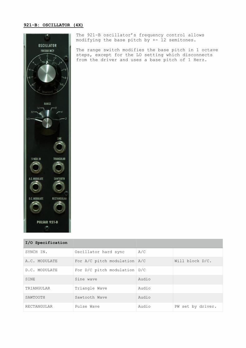
921-B: OSCILLATOR (4X)
The 921-B oscillator’s frequency control allows modifying the base pitch by +- 12 semitones.
The range switch modifies the base pitch in 1 octave steps, except for the LO setting which disconnects from the driver and uses a base pitch of 1 Herz.
I/O Specification
SYNCH IN. Oscillator hard sync A/C
A.C. MODULATE For A/C pitch modulation A/C Will block D/C.
D.C. MODULATE For D/C pitch modulation D/C
SINE Sine wave Audio
TRIANGULAR Triangle Wave Audio
SAWTOOTH Sawtooth Wave Audio
RECTANGULAR Pulse Wave Audio PW set by driver.

CP10: MIXER (3X)
The CP10 is a “clean” mixer. It will not clip or saturate and has a gain of 6 dB. It can be used to mix either A/C or D/C signals.
I/O Specification
OUTPUTS A/C or D/C Inverting output preferred for filter.
INPUTS A/C or D/C

904 A/B/C/D/E: FILTER (2X)
The 904 filter module comes in 5 different flavors:
904-A: Transistor Ladder Low Pass 904-D: Diode Ladder Low Pass 904-E: OTA Low Pass 904-F: State Variable Multimode 904-G: Sallen Key Low Pass
The frequency range switch controls the range of the fixed control voltage according to:
1: 1Hz to 5kHz 2: 4Hz to 20kHz 3: 16Hz to 80kHz (limited by SR)
I/O Specification
SIGNAL INPUT Audio In Audio
SIGNAL OUTPUT Audio Out Audio
CONTROL INPUTS Filter Cutoff CV -6V to 6V Inputs are summed.
NOTCH Notch filter output Audio 904-F only.
BANDPASS Bandpass filter output Audio 904-F only.
HIGHPASS Highpass filter output Audio 904-F only.

911: ENVELOPE GENERATOR (3X)
The 911 envelope generator has a general shape matching the analog equivalent, however the Pulsar version has modified timings with an attack rate closer to that of the Minimoog (which the author happens to like better). Some hard pluck sounds included in the factory presets could not be done without it.
Note that the 911 controls are laid out differently from the typical ADSR. Here you have from top to bottom: Attack, Decay, Release, Sustain
I/O Specification
TRIG IN Gate signal 5V
OUT Envelope signal 0 to 6V

995: ATTENUATOR (3X)
As in the original hardware, the 995 attenuator is internally connected from top to bottom. With only the first input connected, each output is active and can have different gain settings.
Insertions break the internal connections and they become independent attenuators.
I/O Specification
IN A/C or D/C
OUT A/C or D/C

902: VOLTAGE CONTROLLED AMPLIFIER (3X)
The 902 VCA has two modes, linear and exponential. Linear is normally used for the amp envelope and exponential mode is useful for CV signals.
One example of the latter is pitch modulation controlled by a mod wheel. To get a smooth response you route an LFO through a VCA in exponential mode, controlled by the mod wheel CV. Several factory patches do this. They also show how use the fixed control voltage to offset the modulation CV, so that it starts at 0. That way you get an immediate response from the mod wheel. The VCA reacts to CV only from 0 to 6V, so you would otherwise need to bring the mod wheel up to its center before you get a response.
Note that the first output is inverting per original spec!
I/O Specification
SIGNAL INPUTS Audio In Audio Inputs are summed.
SIGNAL OUTPUT Audio Out Audio First output is inverting.
CONTROL INPUTS Amplifier CV 0 to 6V Inputs are summed.

923: FILTERS (1X)
The 923 module has two 1-pole non-resonant filters. Both the low pass and the high pass filter has a cutoff range from 10 Hz to 10 Khz.
The module also includes white and pink noise generators.
I/O Specification
LOW PASS IN Audio In Audio
LOW PASS OUT Audio Out Audio
HIGH PASS IN Audio In Audio
HIGH PASS OUT Audio Out Audio
NOISE SOURCE Audio Out Audio

934: RING MODULATOR (1X)
This is an original Pulsar module that features two independent ring modulators.
I/O Specification
X Audio In
Y Audio In
XY Audio Out
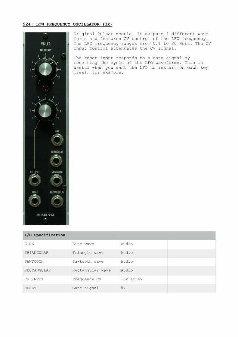
924: LOW FREQUENCY OSCILLATOR (3X)
Original Pulsar module. It outputs 4 different wave forms and features CV control of the LFO frequency. The LFO frequency ranges from 0.1 to 80 Herz. The CV input control attenuates the CV signal.
The reset input responds to a gate signal by resetting the cycle of the LFO waveforms. This is useful when you want the LFO to restart on each key press, for example.
I/O Specification
SINE Sine wave Audio
TRIANGULAR Triangle wave Audio
SAWTOOTH Sawtooth wave Audio
RECTANGULAR Rectangular wave Audio
CV INPUT Frequency CV -6V to 6V
RESET Gate signal 5V

928: SAMPLE & HOLD (1X)
The 928 S&H module samples the input and outputs (a held value) at the rate of either the internal clock or an external clock.
The glide control allows for exponential glide between sampled values, at the specified rate.
I/O Specification
TRIG IN Clock signal LF Audio
CLOCK OUT Clock signal LF Audio
IN Audio In
OUT Audio Out
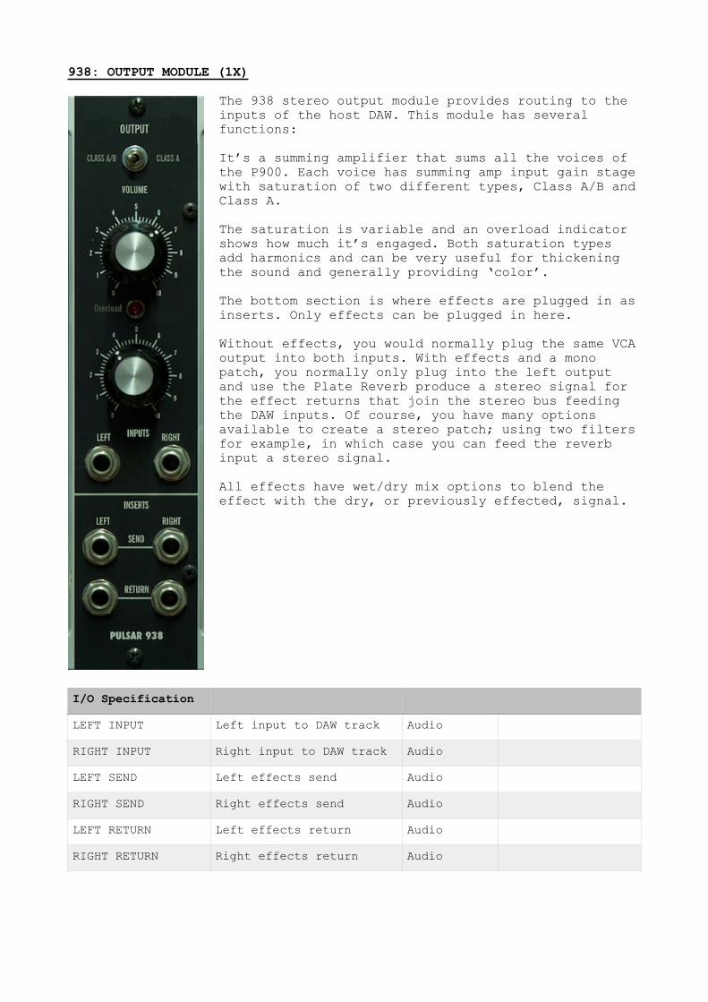
938: OUTPUT MODULE (1X)
The 938 stereo output module provides routing to the inputs of the host DAW. This module has several functions:
It’s a summing amplifier that sums all the voices of the P900. Each voice has summing amp input gain stage with saturation of two different types, Class A/B and Class A.
The saturation is variable and an overload indicator shows how much it’s engaged. Both saturation types add harmonics and can be very useful for thickening the sound and generally providing ‘color’.
The bottom section is where effects are plugged in as inserts. Only effects can be plugged in here.
Without effects, you would normally plug the same VCA output into both inputs. With effects and a mono patch, you normally only plug into the left output and use the Plate Reverb produce a stereo signal for the effect returns that join the stereo bus feeding the DAW inputs. Of course, you have many options available to create a stereo patch; using two filters for example, in which case you can feed the reverb input a stereo signal.
All effects have wet/dry mix options to blend the effect with the dry, or previously effected, signal.
I/O Specification
LEFT INPUT Left input to DAW track Audio
RIGHT INPUT Right input to DAW track Audio
LEFT SEND Left effects send Audio
RIGHT SEND Right effects send Audio
LEFT RETURN Left effects return Audio
RIGHT RETURN Right effects return Audio
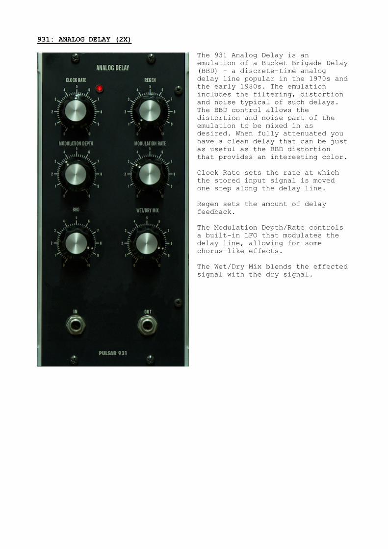
931: ANALOG DELAY (2X)
The 931 Analog Delay is an emulation of a Bucket Brigade Delay (BBD) - a discrete-time analog delay line popular in the 1970s and the early 1980s. The emulation includes the filtering, distortion and noise typical of such delays. The BBD control allows the distortion and noise part of the emulation to be mixed in as desired. When fully attenuated you have a clean delay that can be just as useful as the BBD distortion that provides an interesting color.
Clock Rate sets the rate at which the stored input signal is moved one step along the delay line.
Regen sets the amount of delay feedback.
The Modulation Depth/Rate controls a built-in LFO that modulates the delay line, allowing for some chorus-like effects.
The Wet/Dry Mix blends the effected signal with the dry signal.
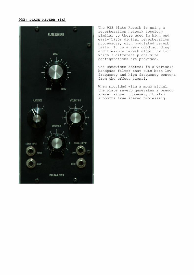
933: PLATE REVERB (1X)
The 933 Plate Reverb is using a reverberation network topology similar to those used in high end early 1980s digital reverberation processors, with modulated reverb tails. It is a very good sounding and flexible reverb algorithm for which 3 different plate size configurations are provided.
The Bandwidth control is a variable bandpass filter that cuts both low frequency and high frequency content from the effect signal.
When provided with a mono signal, the plate reverb generates a pseudo stereo signal. However, it also supports true stereo processing.