puget sound nearshore ecosystem restoration project riverfront...conceptual (10%) design report i...
TRANSCRIPT

May 2012 — Final
Puget SoundNearshore EcosystemRestoration ProjectStrategic Restoration Conceptual Engineering — Design Report
Conceptual (10%) Design Report i Table of Contents
Puget Sound Nearshore Ecosystem Restoration Project Strategic Restoration Conceptual Engineering – Design Report
May 2012 – Final

ii Conceptual (10%) Design Report Table of Contents
Cover photo: Lilliwaup Estuary (ESA)
Conceptual (10%) Design Report iii Table of Contents
Table of Contents
Introduction ......................................................................................................................... 1
Background ......................................................................................................................................... 1
Selection and Screening of Candidate Restoration Actions ............................................................. 2
Restoration Design within PSNERP’s Framework ........................................................................... 8
Definition of Conceptual (10%) Design ....................................................................... 9
Definition of Full Restoration .................................................................................10
Definition of Partial Restoration ............................................................................ 12
Report Organization and Design Assumptions .............................................................................. 12
Design Elements Common to All Actions .................................................................. 13
Rail, Roadway, and Bridge Standards .................................................................... 13
Public Outreach and Property Acquisition ............................................................. 15
Regulatory Compliance and Permitting ................................................................. 16
Sea Level Change Risk Analysis .............................................................................. 17
Cultural/Historical Resources, Contaminant Surveys, and Endangered Species Act Consultation ..................................................................................................... 18
Best Management Practices .................................................................................... 18
Monitoring .............................................................................................................. 19
Adaptive Management ........................................................................................... 20
Operations and Maintenance ................................................................................. 21
Approach to Quantity Estimation ................................................................................................... 21
Applied Geomorphology Guidelines and Hierarchy of Openings ................................................. 22
References......................................................................................................................................... 22
Tables
Table 1. PSNERP’s Candidate Restoration Actions, Local Proponents, and CDT Lead Designer ............................................................................................................................... 4
Table 2. Description of PSNERP’s Restoration Strategies for Puget Sound ..................................... 6
Table 3. Screening Criteria Used to Identify Actions that are Suitable for 10% Design ................... 7
Table 4. Full Restoration Objectives, Target Processes, and Associated Management Measures ............................................................................................................................. 11
Table 5. Methods for Establishing Bridge Elevations (ft) for 10% Design (NAV88) ....................... 13
Table 6. In-Water Work Windows for Estuarine/ Saltwater Habitats in Puget Sound ...................17
Table 7. Puget Sound Nearshore Sea Level Change Analysis (centimeters increase (+) during the period of analysis, 2015 – 2065) .................................................................... 18
Table 8. Standard Monitoring Parameters Used to Denote Key Performance Indicators ............. 19
Figures
Figure 1. Location of PSNERP Candidate Restoration Actions
iv Conceptual (10%) Design Report Table of Contents
Chapters
1. Beaconsfield Feeder Bluff Restoration (#1499)
2. Big Beef Causeway Replacement and Estuary Restoration (#1256)
3. Big Quilcene River Restoration (#1076, 1074, 1077, 1078)
4. Chambers Bay Estuarine and Riparian Enhancement (#1801)
5. Chuckanut Estuary Restoration (#1642)
6. Deepwater Slough Phase 2 (#1101)
7. Deer Harbor Estuary Restoration (#1648)
8. Deschutes River Estuary Restoration (#1003)
9. Duckabush Causeway Replacement and Estuary Restoration (#1012)
10. Dugualla Bay Restoration (#1609)
11. Everett Marshland Tidal Wetland Restoration (#1126)
12. Everett Riverfront Wetland Complexes (#1127)
13. Hamma Hamma Causeway Replacement and Estuary Restoration (#1047)
14. Harper Estuary Restoration Design and Construction (#1505)
15. John’s Creek Estuary Restoration Project (#1447)
16. Kilisut Harbor / Oak Bay Reconnection (#1552)
17. Lilliwaup Causeway Replacement and Estuary Restoration (#1346)
18. Livingston Bay – Diked Farmland & Nearshore Habitat (#1618)
19. McGlinn Island Causeway (#1092)
20. Milltown Island (#1230)
21. Mission Creek Estuary Reconnection (#1237)
22. Nearshore Restoration Strategy for Twin Rivers (#1190)
23. Nooksack River Estuary (#1055)
24. North Fork Levee Setback (#1102)
25. Point Whitney (#1379)
26. Quilceda Estuary Restoration (#1136)
27. Sequalitchew Creek Culvert (#1467)
28. Smith Island Estuary Restoration (#1142)
29. Snohomish Estuary Mainstem Connectivity (#1805)
30. Snow Creek and Salmon Creek Estuary Restoration (#1230)
31. Spencer Island Restoration (#1149)
32. Tahuya Causeway Replacement and Estuary Restoration (#1404)
33. Telegraph Slough - Phase 1 and 2 (#1633, 1635)
34. Twanoh State Park Beach Restoration(#1421)
35. Washington Harbor Tidal Hydrology Restoration Project (#1237)
36. WDNR Marine Lab Bulkhead Softening (#1684)

Conceptual (10%) Design Report v Table of Contents
Appendices
A Action Characterization Report Results
B Quantity Estimate Guidelines
C Applied Geomorphology Guidelines and Benefits of Openings
D Field Maps

Conceptual (10%) Design Report vii Acronyms and Abbreviations
Acronyms and Abbreviations
ACR Action Characterization Report
AASHTO American Association of State Highway and Transportation
Officials
BNSF Burlington Northern Santa Fe
BPA Bonneville Power Administration
CCC Civilian Conservation Corps
CDT Concept Design Team
cfs Cubic feet per second
CMP Corrugated metal pipe
CY Cubic yards
DEM Digital Elevation Model
EHW Extreme high water
ELJ Engineered log jam
FEMA Federal Emergency Management Agency
GI General Investigation
GIS Geographic information system
GLO General Land Office
H-Sheet Hydrographic sheet
HDPE High-density polyethylene
I-5 Interstate 5
LF Linear feet
LiDAR Light Detection and Ranging
LLTK Long Live the Kings
LOTT Lacey-Olympia-Tumwater-Thurston
LWD Large woody debris
MHHW Mean higher high water
MHW Mean high water
MLW Mean low water
MLLW Mean lower low water
mph Miles per hour
MSL Mean sea level
MTL Mean tide line
NAVD North American Vertical Datum
NAS Naval Air Station
NER National Ecosystem Restoration
NMFS National Marine Fisheries Service
NOAA National Oceanic and Atmospheric Administration
NOS National Ocean Service
NPDES National Pollutant Discharge Elimination System
ppt Parts per trillion
PSE Puget Sound Energy
PSNERP Puget Sound Nearshore Ecosystem Restoration Project
PUD Public Utility District
SF Square feet
SLR Sea level rise
viii Conceptual (10%) Design Report Acronyms and Abbreviations
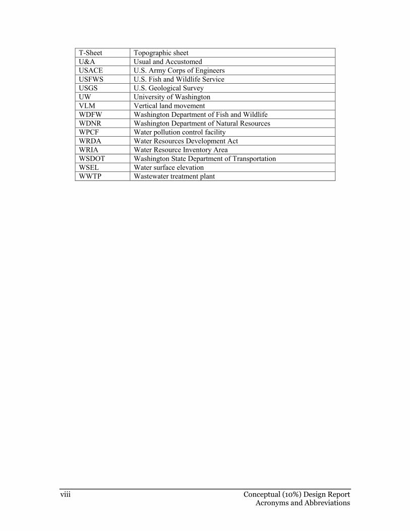
T-Sheet Topographic sheet
U&A Usual and Accustomed
USACE U.S. Army Corps of Engineers
USFWS U.S. Fish and Wildlife Service
USGS U.S. Geological Survey
UW University of Washington
VLM Vertical land movement
WDFW Washington Department of Fish and Wildlife
WDNR Washington Department of Natural Resources
WPCF Water pollution control facility
WRDA Water Resources Development Act
WRIA Water Resource Inventory Area
WSDOT Washington State Department of Transportation
WSEL Water surface elevation
WWTP Wastewater treatment plant
Conceptual (10%) Design Report 1 Introduction
INTRODUCTION
Background
The Washington Department of Fish and Wildlife (WDFW) and the U.S. Army Corps of Engineers (USACE) co-lead PSNERP, a General Investigation (GI) of Puget Sound. PSNERP was initiated to: (1) evaluate significant ecosystem degradation in the Puget Sound Basin; (2) formulate, evaluate, and screen potential strategies to address these problems; and (3) identify actions and projects to restore and preserve critical nearshore habitat. One aim of this multifaceted GI is to secure substantial federal funding (under the Water Resources Development Act or WRDA) for projects that restore the Puget Sound nearshore.
This report presents engineering design concepts for a suite of potential nearshore restoration actions that may be eligible for authorization through WRDA1. PSNERP will use the conceptual design information to assess the costs and benefits of each restoration action and formulate a comprehensive plan for restoring the Puget Sound nearshore. The plan will analyze future conditions with and without a strategic nearshore restoration project. This will allow the USACE and WDFW to compare the benefits of implementing nearshore restoration with the future conditions if no action is taken. The ecological and socioeconomic effects of restoration will be expressed in terms of change in ecosystem outputs. The USACE will use this information to select a portfolio of restoration actions that meet federal cost-effectiveness criteria. The selected actions will be evaluated further to verify their suitability for the National Ecosystem Restoration (NER) Plan proposed to be authorized for implementation.
All of the restoration actions described in this conceptual engineering design report will have the potential to provide important ecological benefits regardless of whether they are deemed appropriate for federal authorization. Some of the actions may be more suitable for implementation at the local level through non-federal programs or partnerships. Report authors and PSNERP team members anticipate that the design information provided by the report will support not only potential implementation of projects through WRDA, but also implementation through other federal and non-federal programs, authorities, and funding sources.
This report was prepared by a team of engineering firms led by Environmental Science Associates (ESA). WDFW hired this team to provide concept-level (10%) design services for an initial suite of candidate restoration actions. ESA’s team (referred to here as the Concept Design Team or CDT) includes ESA PWA (formerly Phillip Williams Associates, now a fully owned subsidiary of ESA); Anchor QEA; Coastal Geologic Services (CGS); KPFF; and Pacific Survey and Engineering (PSE). Completion of conceptual designs and review of the report was supported by PSNERP team members, project proponents who initially identified the potential restoration actions, and USACE technical experts.
1 This report uses the term action instead of project to denote individual restoration efforts that
occur within a larger site. For some sites, such as the Skagit River delta, several actions may be
proposed. The area where an action is proposed is referred to as the action area.
2 Conceptual (10%) Design Report Introduction
Selection and Screening of Candidate Restoration Actions
The candidate restoration actions PSNERP selected for conceptual design were drawn from PSNERP’s analysis of process-based nearshore restoration needs, and from a list of existing restoration opportunities identified by restoration proponents from various governmental and non-governmental organizations throughout the Puget Sound Basin (Figure 1 and Table 1). Each action represents a location where one or more restoration measures can be applied to improve the integrity and resilience of the nearshore ecosystem. According to PSNERP analysis of Puget Sound conditions and program guidance documents, implementing these actions will help achieve nearshore conservation strategies upon which the comprehensive restoration plan for Puget Sound is based (Cereghino et al. 2012) (Table 2).

Conceptual (10%) Design Report 3 Introduction
Figure 1. Location of PSNERP Candidate Restoration Actions
4 Conceptual (10%) Design Report Introduction
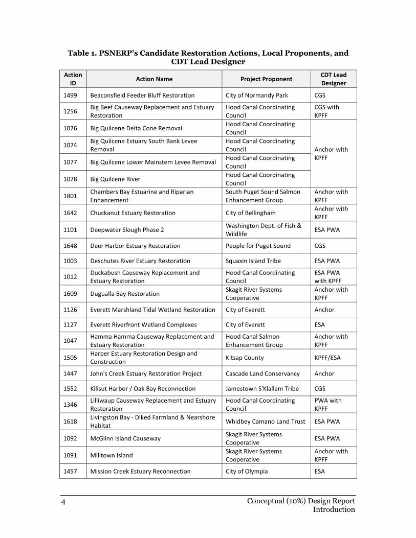
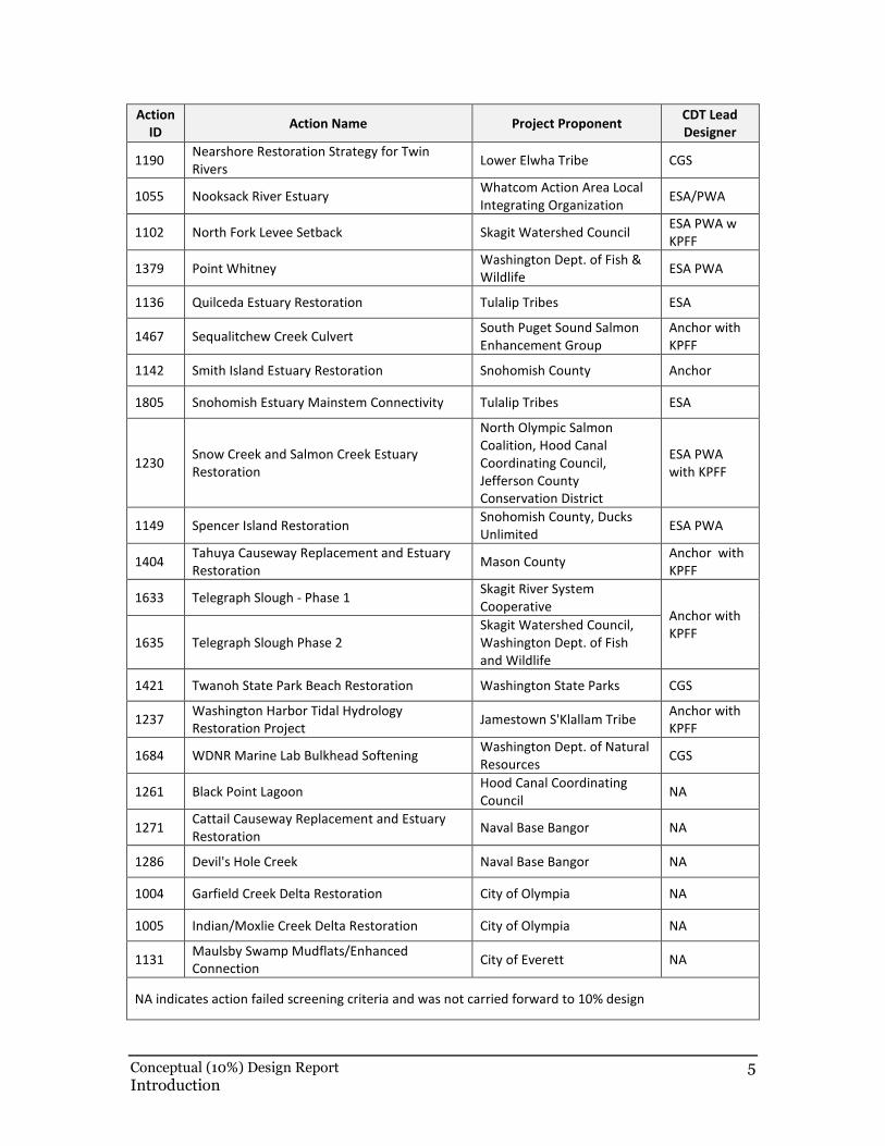
Table 1. PSNERP’s Candidate Restoration Actions, Local Proponents, and CDT Lead Designer
Action
ID Action Name Project Proponent
CDT Lead
Designer
1499 Beaconsfield Feeder Bluff Restoration City of Normandy Park CGS
1256 Big Beef Causeway Replacement and Estuary
Restoration
Hood Canal Coordinating
Council
CGS with
KPFF
1076 Big Quilcene Delta Cone Removal Hood Canal Coordinating
Council
Anchor with
KPFF
1074 Big Quilcene Estuary South Bank Levee
Removal
Hood Canal Coordinating
Council
1077 Big Quilcene Lower Mainstem Levee Removal Hood Canal Coordinating
Council
1078 Big Quilcene River Hood Canal Coordinating
Council
1801 Chambers Bay Estuarine and Riparian
Enhancement
South Puget Sound Salmon
Enhancement Group
Anchor with
KPFF
1642 Chuckanut Estuary Restoration City of Bellingham Anchor with
KPFF
1101 Deepwater Slough Phase 2 Washington Dept. of Fish &
Wildlife ESA PWA
1648 Deer Harbor Estuary Restoration People for Puget Sound CGS
1003 Deschutes River Estuary Restoration Squaxin Island Tribe ESA PWA
1012 Duckabush Causeway Replacement and
Estuary Restoration
Hood Canal Coordinating
Council
ESA PWA
with KPFF
1609 Dugualla Bay Restoration Skagit River Systems
Cooperative
Anchor with
KPFF
1126 Everett Marshland Tidal Wetland Restoration City of Everett Anchor
1127 Everett Riverfront Wetland Complexes City of Everett ESA
1047 Hamma Hamma Causeway Replacement and
Estuary Restoration
Hood Canal Salmon
Enhancement Group
Anchor with
KPFF
1505 Harper Estuary Restoration Design and
Construction Kitsap County KPFF/ESA
1447 John's Creek Estuary Restoration Project Cascade Land Conservancy Anchor
1552 Kilisut Harbor / Oak Bay Reconnection Jamestown S'Klallam Tribe CGS
1346 Lilliwaup Causeway Replacement and Estuary
Restoration
Hood Canal Coordinating
Council
PWA with
KPFF
1618 Livingston Bay - Diked Farmland & Nearshore
Habitat Whidbey Camano Land Trust ESA PWA
1092 McGlinn Island Causeway Skagit River Systems
Cooperative ESA PWA
1091 Milltown Island Skagit River Systems
Cooperative
Anchor with
KPFF
1457 Mission Creek Estuary Reconnection City of Olympia ESA
Conceptual (10%) Design Report 5 Introduction
Action
ID Action Name Project Proponent
CDT Lead
Designer
1190 Nearshore Restoration Strategy for Twin
Rivers Lower Elwha Tribe CGS
1055 Nooksack River Estuary Whatcom Action Area Local
Integrating Organization ESA/PWA
1102 North Fork Levee Setback Skagit Watershed Council ESA PWA w
KPFF
1379 Point Whitney Washington Dept. of Fish &
Wildlife ESA PWA
1136 Quilceda Estuary Restoration Tulalip Tribes ESA
1467 Sequalitchew Creek Culvert South Puget Sound Salmon
Enhancement Group
Anchor with
KPFF
1142 Smith Island Estuary Restoration Snohomish County Anchor
1805 Snohomish Estuary Mainstem Connectivity Tulalip Tribes ESA
1230 Snow Creek and Salmon Creek Estuary
Restoration
North Olympic Salmon
Coalition, Hood Canal
Coordinating Council,
Jefferson County
Conservation District
ESA PWA
with KPFF
1149 Spencer Island Restoration Snohomish County, Ducks
Unlimited ESA PWA
1404 Tahuya Causeway Replacement and Estuary
Restoration Mason County
Anchor with
KPFF
1633 Telegraph Slough - Phase 1 Skagit River System
Cooperative Anchor with
KPFF 1635 Telegraph Slough Phase 2
Skagit Watershed Council,
Washington Dept. of Fish
and Wildlife
1421 Twanoh State Park Beach Restoration Washington State Parks CGS
1237 Washington Harbor Tidal Hydrology
Restoration Project Jamestown S'Klallam Tribe
Anchor with
KPFF
1684 WDNR Marine Lab Bulkhead Softening Washington Dept. of Natural
Resources CGS
1261 Black Point Lagoon Hood Canal Coordinating
Council NA
1271 Cattail Causeway Replacement and Estuary
Restoration Naval Base Bangor NA
1286 Devil's Hole Creek Naval Base Bangor NA
1004 Garfield Creek Delta Restoration City of Olympia NA
1005 Indian/Moxlie Creek Delta Restoration City of Olympia NA
1131 Maulsby Swamp Mudflats/Enhanced
Connection City of Everett NA
NA indicates action failed screening criteria and was not carried forward to 10% design
6 Conceptual (10%) Design Report Introduction
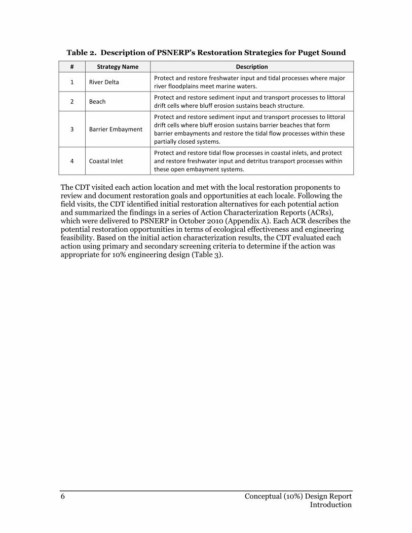
Table 2. Description of PSNERP’s Restoration Strategies for Puget Sound
# Strategy Name Description
1 River Delta Protect and restore freshwater input and tidal processes where major
river floodplains meet marine waters.
2 Beach Protect and restore sediment input and transport processes to littoral
drift cells where bluff erosion sustains beach structure.
3 Barrier Embayment
Protect and restore sediment input and transport processes to littoral
drift cells where bluff erosion sustains barrier beaches that form
barrier embayments and restore the tidal flow processes within these
partially closed systems.
4 Coastal Inlet
Protect and restore tidal flow processes in coastal inlets, and protect
and restore freshwater input and detritus transport processes within
these open embayment systems.
The CDT visited each action location and met with the local restoration proponents to review and document restoration goals and opportunities at each locale. Following the field visits, the CDT identified initial restoration alternatives for each potential action and summarized the findings in a series of Action Characterization Reports (ACRs), which were delivered to PSNERP in October 2010 (Appendix A). Each ACR describes the potential restoration opportunities in terms of ecological effectiveness and engineering feasibility. Based on the initial action characterization results, the CDT evaluated each action using primary and secondary screening criteria to determine if the action was appropriate for 10% engineering design (Table 3).
Conceptual (10%) Design Report 7 Introduction
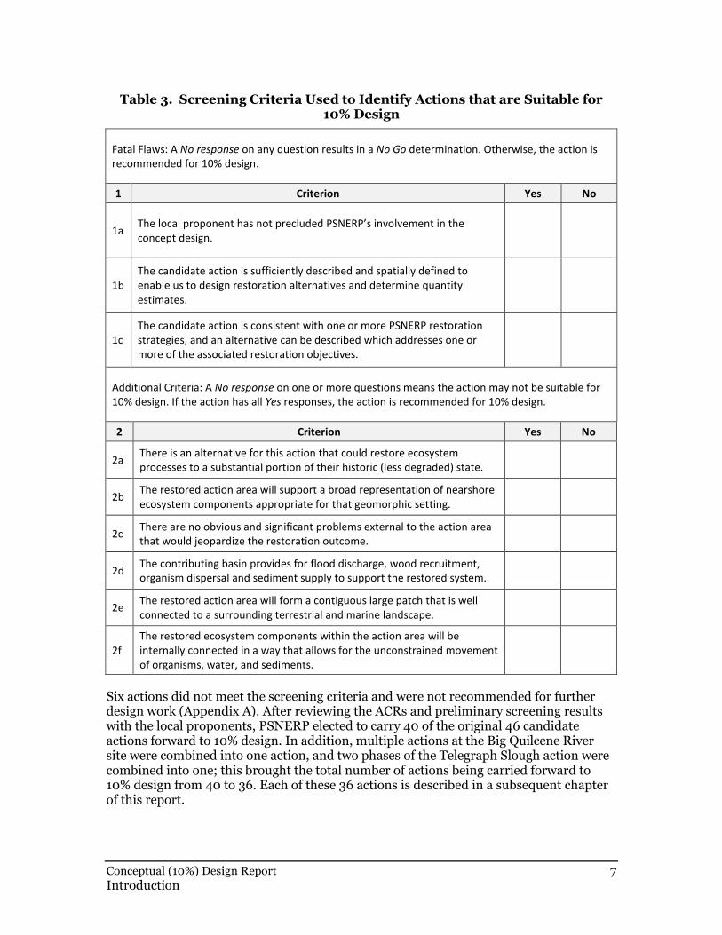
Table 3. Screening Criteria Used to Identify Actions that are Suitable for 10% Design
Fatal Flaws: A No response on any question results in a No Go determination. Otherwise, the action is
recommended for 10% design.
1 Criterion Yes No
1a The local proponent has not precluded PSNERP’s involvement in the
concept design.
1b
The candidate action is sufficiently described and spatially defined to
enable us to design restoration alternatives and determine quantity
estimates.
1c
The candidate action is consistent with one or more PSNERP restoration
strategies, and an alternative can be described which addresses one or
more of the associated restoration objectives.
Additional Criteria: A No response on one or more questions means the action may not be suitable for
10% design. If the action has all Yes responses, the action is recommended for 10% design.
2 Criterion Yes No
2a There is an alternative for this action that could restore ecosystem
processes to a substantial portion of their historic (less degraded) state.
2b The restored action area will support a broad representation of nearshore
ecosystem components appropriate for that geomorphic setting.
2c There are no obvious and significant problems external to the action area
that would jeopardize the restoration outcome.
2d The contributing basin provides for flood discharge, wood recruitment,
organism dispersal and sediment supply to support the restored system.
2e The restored action area will form a contiguous large patch that is well
connected to a surrounding terrestrial and marine landscape.
2f
The restored ecosystem components within the action area will be
internally connected in a way that allows for the unconstrained movement
of organisms, water, and sediments.
Six actions did not meet the screening criteria and were not recommended for further design work (Appendix A). After reviewing the ACRs and preliminary screening results with the local proponents, PSNERP elected to carry 40 of the original 46 candidate actions forward to 10% design. In addition, multiple actions at the Big Quilcene River site were combined into one action, and two phases of the Telegraph Slough action were combined into one; this brought the total number of actions being carried forward to 10% design from 40 to 36. Each of these 36 actions is described in a subsequent chapter of this report.
8 Conceptual (10%) Design Report Introduction
Restoration Design within PSNERP’s Framework
PSNERP’s restoration strategies are aimed at restoring damaged or degraded ecosystem processes. Process-based restoration involves making intentional changes to an ecosystem to allow erosion, accretion, tidal exchange, accumulation of wood debris, and other natural process to occur. Process-based restoration is often distinguished from species-based restoration which aims to improve the services an ecosystem provides to a single species or group of species as opposed to improving the entire ecosystem. It is anticipated that process-based restoration will deliver benefits to the diverse array of species that rely upon nearshore ecosystems in a manner that is sustainable and reduces the need for future interventions at the restored site. PSNERP has documented representative relationships between “valued ecosystem components”, including juvenile salmonids, forage fish, and shorebirds, as part of a series of technical reports, available on the program website (http://www.pugetsoundnearshore.org/technical_reports.htm).
In PSNERP’s framework, each candidate restoration action involves removing one or more ecosystem stressors using specific management measures. Stressors are physical alterations that interrupt, preclude, or displace nearshore processes. PSNERP documented the presence of the following stressors throughout Puget Sound as part of the Strategic Needs Assessment (Schlenger et al. 2011): nearshore fill, tidal barriers, shoreline armoring, railroads, nearshore roads, marinas, breakwaters and jetties, overwater structures, dams, stream crossings, impervious surfaces, and land cover development.
PSNERP used stressor information to calculate a degradation score for a series of nearshore analysis units. The CDT supplemented this relatively coarse scale information on stressors with additional site-specific information gathered during the field investigations to create restoration concepts for each action. The design concepts presented here document the amount of each stressor to be removed at each action location. PSNERP will use the information concerning stressor removal to recalculate the degradation scores and quantify the benefits of each restoration alternative.
Management measures are the restoration, rehabilitation, and enhancement activities (as well as protection, management, and regulatory endeavors) that remove stressors to recover or improve nearshore ecosystems. PSNERP defined 21 management measures for protecting and restoring Puget Sound (Clancy et al. 2009; http://www.pugetsoundnearshore.org/technical_papers/management_measures.pdf). Each candidate restoration action involves applying one or more of these management measures to achieve the site-specific restoration objectives. The measures that are the primary focus of this conceptual design report are the ones that have the most direct effect on nearshore processes and require in-depth engineering analysis, including:
• Topography Restoration: dredging, fill removal, or addition of surface material so that the physical structure of beaches, shorelines, and tidal wetlands can be restored.
• Armor Removal or Modification: removal of coastal erosion protection structures, including rock revetments, bulkheads, and retaining walls, to reinitiate sediment delivery and transport within beach systems.
• Hydraulic Modification: modification of culverts, tide gates, or levees to improve tidal or fluvial connectivity and the associated conditions in marsh and lagoon habitats.
Conceptual (10%) Design Report 9 Introduction
• Berm or Dike Removal or Modification: removal of structures to restore tidal inundation and restoration of tidal wetland ecosystems.
• Channel Rehabilitation or Creation: restoration or creation of tidal, alluvial, and distributary channels to restore the natural movement and exchange of water, sediment, and/or detritus.
Other management measures such as Beach Nourishment, Contaminant Removal/ Remediation, Debris Removal, Groin Removal, Invasive Species Control, Large Wood Placement, Physical Exclusion, Overwater Structure Removal or Modification, Species/ Habitat Enhancement, Substrate Modification, Reintroduction of Native Animals, and Revegetation are used for some actions depending on the specific restoration opportunities available. Management measures such as Public Outreach/ Education, Habitat Protection Policies and Regulations, and Property Acquisition and Conservation are common to all actions.
Definition of Conceptual (10%) Design
Conceptual (10%) design is the first step in the restoration design sequence. Typically projects move from the concept stage (10%) to preliminary design (35%) to final design (which often involves 60, 90, and 100% design plans). While there are no precise definitions for 10% design, conceptual design generally involves identifying site-scale restoration alternatives for an action area and comparing them in terms of their relative costs, benefits, and feasibility. Action area boundaries were estimated to represent the area affected by the proposed restoration actions. A more precise, but still approximate, estimate of the lands required for construction (referred to as required project lands) was also calculated for each action. The action area and required project lands boundaries are shown in the figures and drawings that accompany each action. For purposes of this contract, 10% design involves the following:
• Describing site conditions and restoration opportunities;
• Describing how specific management measures will be applied to remove stressors and restore processes;
• Identifying the potential need for land acquisition;
• Describing the primary design considerations that might affect feasibility, cost and/or success of the project;
• Describing the ecological evolution of the restored site;
• Quantifying the type and amount of stressor removal at each action area;
• Describing uncertainties and/or risks associated with property acquisition, flooding, weak soils, contamination, etc.;
• Assessing risks caused by projected sea level change;
• Describing additional information needs; and
• Estimating quantities for all the major design elements.
A major goal of the 10% design process is defining data gaps and uncertainties that will need to be addressed in subsequent design phases, since detailed site investigations are typically not performed at the conceptual design stage. Subsequent design studies could include, for example, property boundary surveys, topographic surveys, geotechnical analyses, contaminant tests, cultural resources assessments, and hydrodynamic models.
10 Conceptual (10%) Design Report Introduction
Ideally, the conceptual design process enables a project proponent to select a preferred alternative for each action that can be developed in more detail during the later design stages.
To ensure that a feasible and effective restoration alternative can be found for each of PSNERP’s candidate actions, the CDT attempted to identify a broad spectrum of what might be possible within each action area. Thus, each action is represented in terms of a full restoration alternative and a partial restoration alternative. Bracketing a wide range of restoration possibilities for each action in this way bolsters PSNERP’s ability to:
• Identify the combination of restoration measures that maximizes ecosystem benefits compared to costs, consistent with federal ecosystem restoration objectives;
• Select a subset of actions to move forward to preliminary design (35%); and
• Secure authorization for federal funding sufficient to implement a comprehensive restoration plan for Puget Sound (even though the plan may be scaled back as the design progresses).
Definition of Full Restoration
For each candidate action, the full restoration alternative is designed to maximize ecological benefits by fully removing stressors—regardless of cost. As a result, the full restoration alternative for each action is not necessarily the most cost effective way to restore the site. Optimizing ecological benefits means that in some cases, the full restoration includes activities such as excavation of starter channels or tidal channels to trigger natural processes and accelerate site evolution. For planning purposes, the full restoration alternative assumes that private properties can be acquired and that most infrastructure such as secondary roads and local utilities can be modified, relocated, or removed to fully restore processes. Major infrastructure such as regional transmission lines, state highways, and railroads are treated as constraints to full restoration and addressed accordingly. Although these assumptions are important for fully delineating the scope of federal authority that would be needed to implement these actions using WRDA appropriations, PSNERP recognizes that the full restoration alternative may not be appropriate for some actions. In particular, PSNERP recognizes that acquisition of private lands and infrastructure relocation hinge on landowner willingness, stakeholder support, and myriad other factors that have not been fully investigated at the concept design stage.
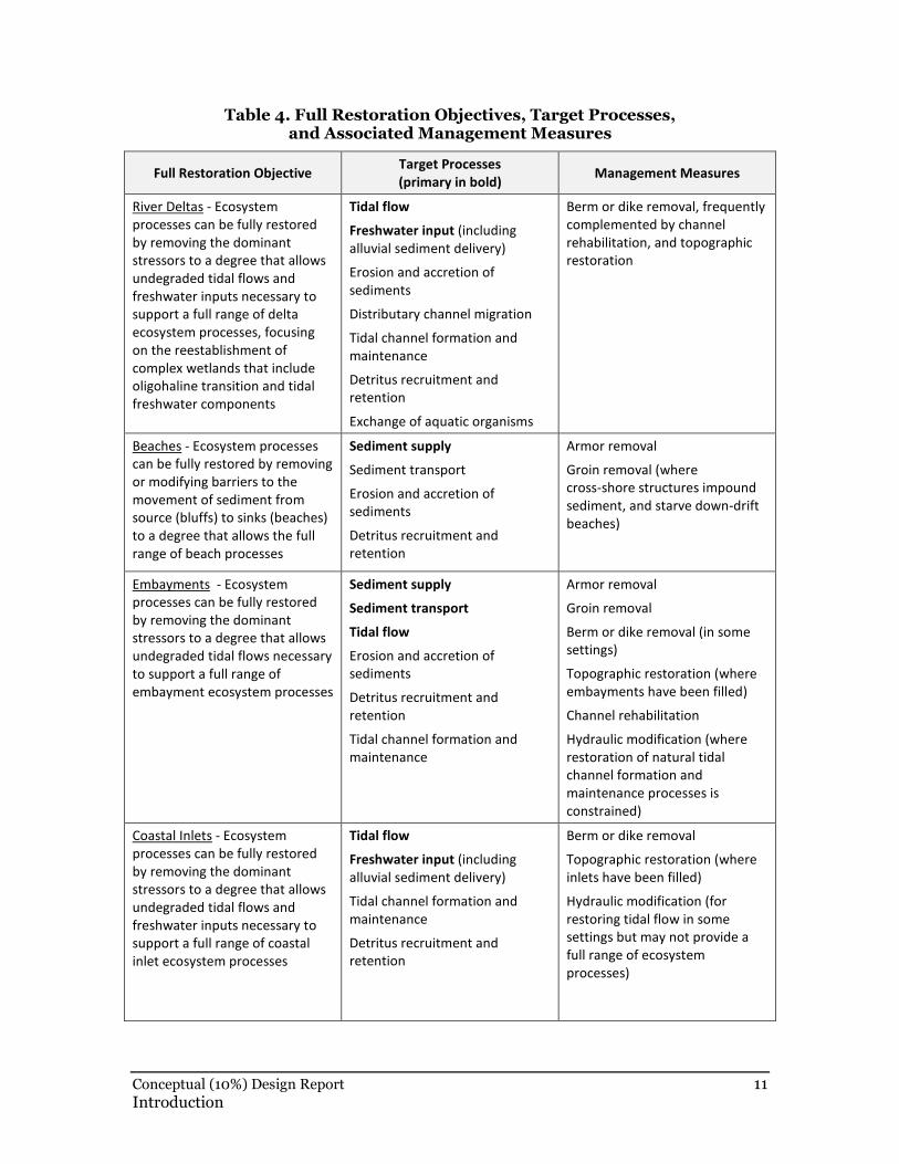
Full restoration as presented here involves applying specific process-based management measures to remove the causes of process degradation, which vary depending on the strategy/shoreform (Table 4). The description of a full restoration alternative is intended to assist the planning process by describing a site’s near-maximum potential. In most cases, PSNERP recognizes that site-specific feasible, cost-effective, and socially acceptable alternatives may be scaled back through subsequent steps in the design process.
Conceptual (10%) Design Report 11 Introduction
Table 4. Full Restoration Objectives, Target Processes, and Associated Management Measures
Full Restoration Objective Target Processes
(primary in bold) Management Measures
River Deltas - Ecosystem
processes can be fully restored
by removing the dominant
stressors to a degree that allows
undegraded tidal flows and
freshwater inputs necessary to
support a full range of delta
ecosystem processes, focusing
on the reestablishment of
complex wetlands that include
oligohaline transition and tidal
freshwater components
Tidal flow
Freshwater input (including
alluvial sediment delivery)
Erosion and accretion of
sediments
Distributary channel migration
Tidal channel formation and
maintenance
Detritus recruitment and
retention
Exchange of aquatic organisms
Berm or dike removal, frequently
complemented by channel
rehabilitation, and topographic
restoration
Beaches - Ecosystem processes
can be fully restored by removing
or modifying barriers to the
movement of sediment from
source (bluffs) to sinks (beaches)
to a degree that allows the full
range of beach processes
Sediment supply
Sediment transport
Erosion and accretion of
sediments
Detritus recruitment and
retention
Armor removal
Groin removal (where
cross-shore structures impound
sediment, and starve down-drift
beaches)
Embayments - Ecosystem
processes can be fully restored
by removing the dominant
stressors to a degree that allows
undegraded tidal flows necessary
to support a full range of
embayment ecosystem processes
Sediment supply
Sediment transport
Tidal flow
Erosion and accretion of
sediments
Detritus recruitment and
retention
Tidal channel formation and
maintenance
Armor removal
Groin removal
Berm or dike removal (in some
settings)
Topographic restoration (where
embayments have been filled)
Channel rehabilitation
Hydraulic modification (where
restoration of natural tidal
channel formation and
maintenance processes is
constrained)
Coastal Inlets - Ecosystem
processes can be fully restored
by removing the dominant
stressors to a degree that allows
undegraded tidal flows and
freshwater inputs necessary to
support a full range of coastal
inlet ecosystem processes
Tidal flow
Freshwater input (including
alluvial sediment delivery)
Tidal channel formation and
maintenance
Detritus recruitment and
retention
Berm or dike removal
Topographic restoration (where
inlets have been filled)
Hydraulic modification (for
restoring tidal flow in some
settings but may not provide a
full range of ecosystem
processes)
12 Conceptual (10%) Design Report Introduction
Definition of Partial Restoration
Each candidate action is also represented by a partial restoration alternative. The partial restoration alternative differs from full restoration in that it: (1) generally does not fully remove stressors, and (2) is typically more constrained in terms of the scope, scale, and/or complexity of restoration features involved. Partial restoration alternatives typically involve fewer management measures, have smaller or more constrained tidal openings, have a smaller footprint, and/or require less property acquisition than full restoration. In some cases, the partial restoration alternative is configured to take advantage of properties that are believed to have willing owners (which needs to be confirmed). Partial restoration generally reflects the local proponent’s needs and desires and may include public access features such as trails, boat launches, and other amenities that are necessary to satisfy local interests.
As an example, the full restoration alternative for the Chuckanut Estuary Restoration action (Chapter 5, #1642) involves removing the existing railroad berm crossing the estuary and replacing it with a bridge. The partial restoration alternative, by comparison, removes only 290 feet of the berm. The smaller opening in the partial restoration alternative was sized to provide the desired tidal velocities and complexity of tidal circulation and wave action within the estuary, while minimizing the engineering complexities associated with replacing over 2,000 linear feet of an active railroad line. Despite not achieving full removal of stressors, the CDT attempted to define partial restoration alternatives for this and other actions which would:
• Support a wide range of ecosystem processes;
• Provide wide representation of ecosystem components appropriate for the shoreform;
• Include contiguous large patches that are well connected to each other and to a surrounding alluvial, terrestrial, and marine landscape;
• Be internally connected to allow for the unconstrained movement of organisms, water, and sediments; and
• Ensure adequate flood discharge, wood recruitment, organism dispersal, and sediment supply to support functions.
Report Organization and Design Assumptions
Each of the following 36 chapters of this report describes the 10% design concept for a candidate restoration action. Each chapter includes background information on the action area, historical maps, an overview of the design concept, and details for the major restoration features. The text is organized to emphasize issues that are important to PSNERP’s restoration framework: stressors and management measures. Plan view and cross section drawings depicting the key design elements are provided for the full and partial restoration alternatives for each action. A digital geodatabase also accompanies this report. The geodatabase has additional geospatial information on the restoration features and elements for ach action, which in some cases is not depicted easily on the (two-dimensional) plan view or cross section drawings. An engineer’s estimate of quantities is also provided for each action and each alternative. Additional maps depicting current and historic shoreform type for each action area are included in Appendix D.
Conceptual (10%) Design Report 13 Introduction
This report presents design concepts to support development of a comprehensive restoration plan for Puget Sound; these designs are not ready for construction. The designs are intended to help PSNERP determine the least-costly way of attaining its Sound-wide restoration objectives. This report does not identify or address all of the social, political, or economic implications of the proposed restoration actions. That work will occur as part of subsequent design and analysis.
Design Elements Common to All Actions
The restoration actions described in this report share a number of common elements and have some similar underlying design assumptions. This section describes those commonalities to minimize repetition of information in each of the design chapters that follow.
Rail, Roadway, and Bridge Standards
Many of the actions involve replacement or modifications of transportation facilities such as railroads, roadways, and bridges. For the 10% design, the CDT assumes that all road and bridge work will conform to Washington State Department of Transportation (WSDOT) standards and comply with local agency requirements. Rail modifications would need to be coordinated with rail operators including Burlington Northern Santa Fe (BNSF) and will conform to their standards. Deviations, if needed, would be identified in subsequent stages of design.
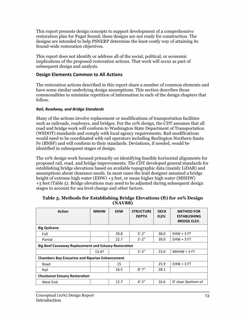
The 10% design work focused primarily on identifying feasible horizontal alignments for proposed rail, road, and bridge improvements. The CDT developed general standards for establishing bridge elevations based on available topographic data (mainly LiDAR) and assumptions about clearance needs. In most cases the lead designer assumed a bridge height of extreme high water (EHW) +3 feet, or mean higher high water (MHHW) +3 feet (Table 5). Bridge elevations may need to be adjusted during subsequent design stages to account for sea level change and other factors.
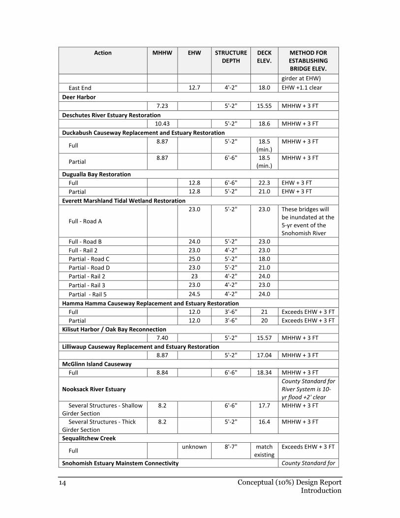
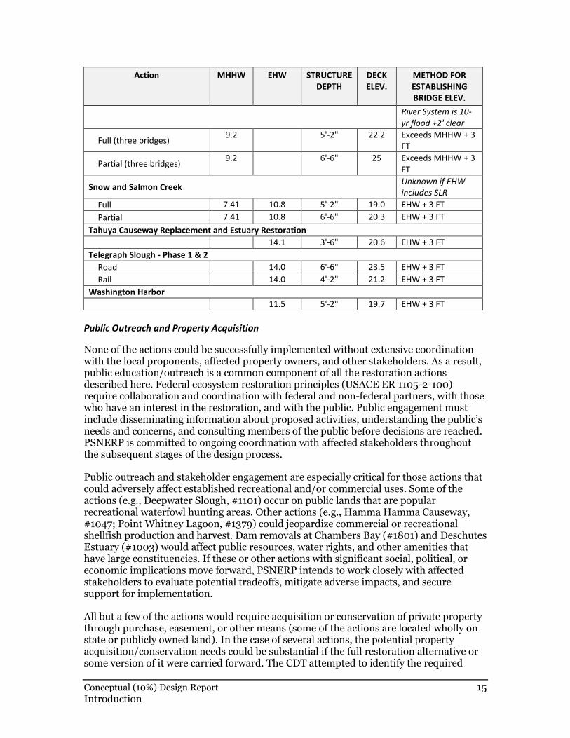
Table 5. Methods for Establishing Bridge Elevations (ft) for 10% Design (NAV88)
Action MHHW EHW STRUCTURE
DEPTH
DECK
ELEV.
METHOD FOR
ESTABLISHING
BRIDGE ELEV.
Big Quilcene
Full 29.8 5'-2" 38.0 EHW + 3 FT
Partial 22.7 5'-2" 39.0 EHW + 3 FT
Big Beef Causeway Replacement and Estuary Restoration
13.47 5'-2" 23.0 MHHW + 3 FT
Chambers Bay Estuarine and Riparian Enhancement
Road 15 25.9 EHW + 3 FT
Rail 16.5 8'-7" 28.1
Chuckanut Estuary Restoration
West End 12.7 4'-2" 16.6 0' clear (bottom of
14 Conceptual (10%) Design Report Introduction
Action MHHW EHW STRUCTURE
DEPTH
DECK
ELEV.
METHOD FOR
ESTABLISHING
BRIDGE ELEV.
girder at EHW)
East End 12.7 4'-2" 18.0 EHW +1.1 clear
Deer Harbor
7.23 5'-2" 15.55 MHHW + 3 FT
Deschutes River Estuary Restoration
10.43 5'-2" 18.6 MHHW + 3 FT
Duckabush Causeway Replacement and Estuary Restoration
Full 8.87 5'-2" 18.5
(min.)
MHHW + 3 FT
Partial 8.87 6'-6" 18.5
(min.)
MHHW + 3 FT
Dugualla Bay Restoration
Full 12.8 6'-6" 22.3 EHW + 3 FT
Partial 12.8 5'-2" 21.0 EHW + 3 FT
Everett Marshland Tidal Wetland Restoration
Full - Road A
23.0 5'-2" 23.0 These bridges will
be inundated at the
5-yr event of the
Snohomish River
Full - Road B 24.0 5'-2" 23.0
Full - Rail 2 23.0 4'-2" 23.0
Partial - Road C 25.0 5'-2" 18.0
Partial - Road D 23.0 5'-2" 21.0
Partial - Rail 2 23 4'-2" 24.0
Partial - Rail 3 23.0 4'-2" 23.0
Partial - Rail 5 24.5 4'-2" 24.0
Hamma Hamma Causeway Replacement and Estuary Restoration
Full 12.0 3'-6" 21 Exceeds EHW + 3 FT
Partial 12.0 3'-6" 20 Exceeds EHW + 3 FT
Kilisut Harbor / Oak Bay Reconnection
7.40 5'-2" 15.57 MHHW + 3 FT
Lilliwaup Causeway Replacement and Estuary Restoration
8.87 5'-2" 17.04 MHHW + 3 FT
McGlinn Island Causeway
Full 8.84 6'-6" 18.34 MHHW + 3 FT
Nooksack River Estuary
County Standard for
River System is 10-
yr flood +2' clear
Several Structures - Shallow
Girder Section
8.2 6'-6" 17.7 MHHW + 3 FT
Several Structures - Thick
Girder Section
8.2 5'-2" 16.4 MHHW + 3 FT
Sequalitchew Creek
Full unknown 8'-7" match
existing
Exceeds EHW + 3 FT
Snohomish Estuary Mainstem Connectivity County Standard for
Conceptual (10%) Design Report 15 Introduction
Action MHHW EHW STRUCTURE
DEPTH
DECK
ELEV.
METHOD FOR
ESTABLISHING
BRIDGE ELEV.
River System is 10-
yr flood +2' clear
Full (three bridges) 9.2 5'-2" 22.2 Exceeds MHHW + 3
FT
Partial (three bridges) 9.2 6'-6" 25 Exceeds MHHW + 3
FT
Snow and Salmon Creek Unknown if EHW
includes SLR
Full 7.41 10.8 5'-2" 19.0 EHW + 3 FT
Partial 7.41 10.8 6'-6" 20.3 EHW + 3 FT
Tahuya Causeway Replacement and Estuary Restoration
14.1 3'-6" 20.6 EHW + 3 FT
Telegraph Slough - Phase 1 & 2
Road 14.0 6'-6" 23.5 EHW + 3 FT
Rail 14.0 4'-2" 21.2 EHW + 3 FT
Washington Harbor
11.5 5'-2" 19.7 EHW + 3 FT
Public Outreach and Property Acquisition
None of the actions could be successfully implemented without extensive coordination with the local proponents, affected property owners, and other stakeholders. As a result, public education/outreach is a common component of all the restoration actions described here. Federal ecosystem restoration principles (USACE ER 1105-2-100) require collaboration and coordination with federal and non-federal partners, with those who have an interest in the restoration, and with the public. Public engagement must include disseminating information about proposed activities, understanding the public’s needs and concerns, and consulting members of the public before decisions are reached. PSNERP is committed to ongoing coordination with affected stakeholders throughout the subsequent stages of the design process.
Public outreach and stakeholder engagement are especially critical for those actions that could adversely affect established recreational and/or commercial uses. Some of the actions (e.g., Deepwater Slough, #1101) occur on public lands that are popular recreational waterfowl hunting areas. Other actions (e.g., Hamma Hamma Causeway, #1047; Point Whitney Lagoon, #1379) could jeopardize commercial or recreational shellfish production and harvest. Dam removals at Chambers Bay (#1801) and Deschutes Estuary (#1003) would affect public resources, water rights, and other amenities that have large constituencies. If these or other actions with significant social, political, or economic implications move forward, PSNERP intends to work closely with affected stakeholders to evaluate potential tradeoffs, mitigate adverse impacts, and secure support for implementation.
All but a few of the actions would require acquisition or conservation of private property through purchase, easement, or other means (some of the actions are located wholly on state or publicly owned land). In the case of several actions, the potential property acquisition/conservation needs could be substantial if the full restoration alternative or some version of it were carried forward. The CDT attempted to identify the required
16 Conceptual (10%) Design Report Introduction
project lands including lands to be acquired for each action based on readily available parcel data so that property needs could be considered when selecting a preferred alternative and weighing overall costs and benefits. The CDT determined the area of required projects lands by estimating the area directly affected by proposed construction activities including access and staging. Property requirements also depend on the area of potential hydraulic effect (i.e., area influenced by inundation or flooding following restoration) associated with each action, as hydraulic considerations may trigger the need for additional acquisition or easements (e.g., flowage easements). For most actions, the area of potential hydraulic effect is the same as the construction footprint, but for some actions the potential hydraulic effect extends beyond the area needed for construction. The required project lands area (i.e., the construction footprint) and the area of potential hydraulic effect are depicted on the plan view drawings for each action and/or in the geodatabase that corresponds to the project.
The willingness of property owners to make their lands available for restoration is often unknown at this point, and will need to be assessed during subsequent design stages. Federal ecosystem restoration principles specify that land acquisition should be minimized (generally not more than 25% of total project costs).
Regulatory Compliance and Permitting
All of the actions involve work in wetlands, waters of the state/waters of the U.S., and other sensitive or protected habitats. The actions will therefore need to comply with multiple and sometimes overlapping local, state, and federal laws, including but not limited to:
• National Environmental Policy Act
• State Environmental Policy Act
• Clean Water Act Sections 404 and 401
• National Pollutant Discharge Elimination System
• Endangered Species Act
• National Historic Preservation Act
• State Hydraulic Code
• State Shoreline Management Act
• Local Development Codes and Critical Areas Ordinances
The specific permits required and agencies involved will vary depending on the location and nature of the work associated with each action. A complete description of the permit/regulatory needs will be determined during subsequent design stages. Even though the proposed restoration actions will have beneficial effects on nearshore resources, impacts of construction (e.g., pile driving, excavation, dewatering, etc.) will need to be fully evaluated pursuant to applicable statutes and policies.
All of the actions that involve work below the ordinary high water mark of any waterbody will need to adhere to timing restrictions mandated by state and federal agencies. The restrictions are designed to prevent in-water construction activity during periods of salmonid migration and/or forage fish spawning. Regulatory agencies determine specific “windows” when in-water work is allowed on a case-by-case basis depending on the

Conceptual (10%) Design Report 17 Introduction
location of the work and the species present. Table 6 provides the approximate work “windows” for estuarine/saltwater habitats in Puget Sound.
Table 6. In-Water Work Windows for Estuarine/ Saltwater Habitats in Puget Sound
Species Allowed in-water work window (approximate)
Salmon and bull trout July to March
Herring April to January
Sand lance March to October
Surf smelt April to September
Sea Level Change Risk Analysis
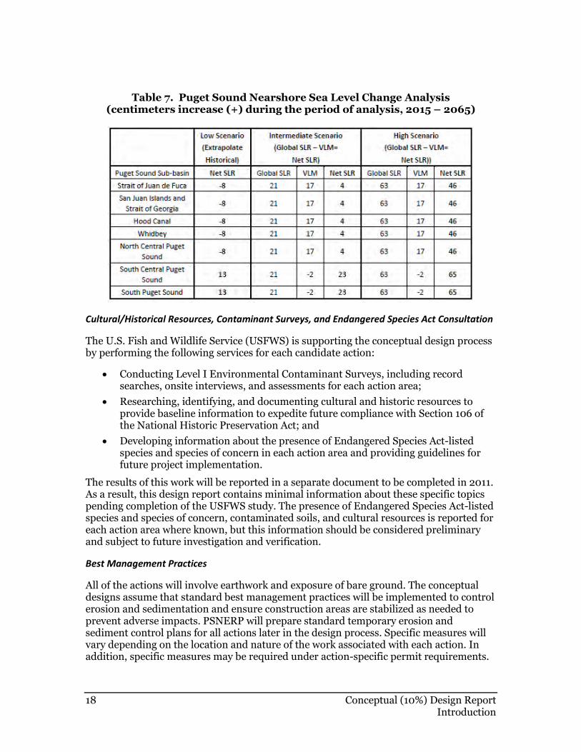
PSNERP is required to consider the effects of projected changes in sea level on proposed restoration actions2. To fulfill this requirement, the CDT qualitatively evaluated each action and each restoration alternative in terms of three scenarios that USACE uses for coastal investigations: “low,” “intermediate,” and “high” (Table 7). Local sea level rise change is produced by the combined effects of global sea level rise and local factors such as vertical land movement (VLM) (e.g., tectonic movement, isostatic rebound) and seasonal ocean elevation changes due to atmospheric circulation effects (Mote et al. 2008). Due to the position of tectonic plates, rates of VLM vary around Puget Sound with some areas experiencing uplift and others undergoing subsidence. Areas of uplift, such as the northwest portion of the Olympic Peninsula along the Strait of Juan de Fuca, may exceed projected sea level rise rates and result in a decrease in sea level (as shown in Table 7). SLR projections for each action will be refined using localized tide gauge data during later design stages.
The data represented in these scenarios are coarse approximations of sea level trends for a period of 50 years into the future with changes that may be nearly imperceptible from year to year. For these and other reasons, readers are advised not to place too much significance on absolute numbers, or significant digits, in this rapidly evolving area of scientific study.
2 See Corps of Engineers Circular EC 1165-2-211 regarding “Incorporating Sea-Level Change
Considerations in Civil Works Programs”(140.194.76.129/publications/eng-circulars/ec1165-2-
211/entire.pdf).
18 Conceptual (10%) Design Report Introduction
Table 7. Puget Sound Nearshore Sea Level Change Analysis (centimeters increase (+) during the period of analysis, 2015 – 2065)
Cultural/Historical Resources, Contaminant Surveys, and Endangered Species Act Consultation
The U.S. Fish and Wildlife Service (USFWS) is supporting the conceptual design process by performing the following services for each candidate action:
• Conducting Level I Environmental Contaminant Surveys, including record searches, onsite interviews, and assessments for each action area;
• Researching, identifying, and documenting cultural and historic resources to provide baseline information to expedite future compliance with Section 106 of the National Historic Preservation Act; and
• Developing information about the presence of Endangered Species Act-listed species and species of concern in each action area and providing guidelines for future project implementation.
The results of this work will be reported in a separate document to be completed in 2011. As a result, this design report contains minimal information about these specific topics pending completion of the USFWS study. The presence of Endangered Species Act-listed species and species of concern, contaminated soils, and cultural resources is reported for each action area where known, but this information should be considered preliminary and subject to future investigation and verification.
Best Management Practices
All of the actions will involve earthwork and exposure of bare ground. The conceptual designs assume that standard best management practices will be implemented to control erosion and sedimentation and ensure construction areas are stabilized as needed to prevent adverse impacts. PSNERP will prepare standard temporary erosion and sediment control plans for all actions later in the design process. Specific measures will vary depending on the location and nature of the work associated with each action. In addition, specific measures may be required under action-specific permit requirements.
Conceptual (10%) Design Report 19 Introduction
A complete description of best management practices will be determined during subsequent design stages.
Monitoring
Each restoration action has associated monitoring needs and opportunities that are necessary for achieving success. Monitoring is essential for informing our understanding of restoration as a science, and for providing accountability to project proponents and stakeholders.
Although it is difficult at the conceptual design stage to identify all of the monitoring opportunities and needs that a given action presents, the CDT attempted to identify preliminary performance indicators for each candidate action that could provide valuable information for assessing and documenting restoration outcomes.
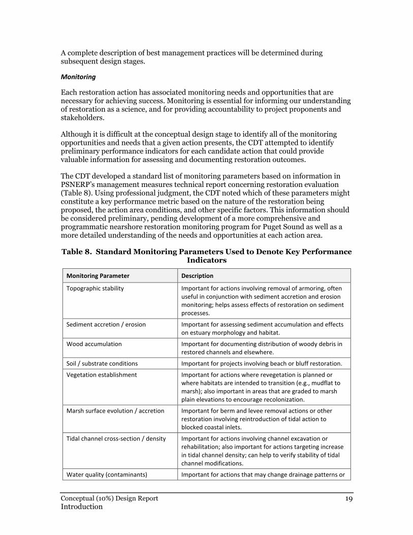
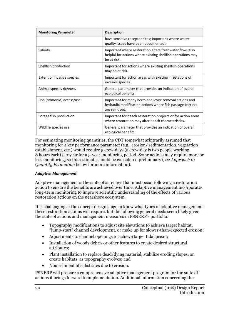
The CDT developed a standard list of monitoring parameters based on information in PSNERP’s management measures technical report concerning restoration evaluation (Table 8). Using professional judgment, the CDT noted which of these parameters might constitute a key performance metric based on the nature of the restoration being proposed, the action area conditions, and other specific factors. This information should be considered preliminary, pending development of a more comprehensive and programmatic nearshore restoration monitoring program for Puget Sound as well as a more detailed understanding of the needs and opportunities at each action area.
Table 8. Standard Monitoring Parameters Used to Denote Key Performance Indicators
Monitoring Parameter Description
Topographic stability Important for actions involving removal of armoring, often
useful in conjunction with sediment accretion and erosion
monitoring; helps assess effects of restoration on sediment
processes.
Sediment accretion / erosion Important for assessing sediment accumulation and effects
on estuary morphology and habitat.
Wood accumulation Important for documenting distribution of woody debris in
restored channels and elsewhere.
Soil / substrate conditions Important for projects involving beach or bluff restoration.
Vegetation establishment Important for actions where revegetation is planned or
where habitats are intended to transition (e.g., mudflat to
marsh); also important in areas that are graded to marsh
plain elevations to encourage recolonization.
Marsh surface evolution / accretion Important for berm and levee removal actions or other
restoration involving reintroduction of tidal action to
blocked coastal inlets.
Tidal channel cross-section / density Important for actions involving channel excavation or
rehabilitation; also important for actions targeting increase
in tidal channel density; can help to verify stability of tidal
channel modifications.
Water quality (contaminants) Important for actions that may change drainage patterns or
20 Conceptual (10%) Design Report Introduction
Monitoring Parameter Description
have sensitive receptor sites; important where water
quality issues have been documented.
Salinity Important where restoration alters freshwater flow; also
helpful for actions where existing shellfish operations may
be at risk.
Shellfish production Important for actions where existing shellfish operations
may be at risk.
Extent of invasive species Important for action areas with existing infestations of
invasive species.
Animal species richness General parameter that provides an indication of overall
ecological benefits.
Fish (salmonid) access/use Important for many berm and levee removal actions and
hydraulic modification actions where fish passage barriers
are removed.
Forage fish production Important for beach restoration projects or for action areas
where restoration may alter beach characteristics.
Wildlife species use General parameter that provides an indication of overall
ecological benefits.
For estimating monitoring quantities, the CDT somewhat arbitrarily assumed that monitoring for a key performance parameter (e.g., erosion/ sedimentation, vegetation establishment, etc.) would require 5 crew-days (a crew-day is two people working 8 hours each) per year for a 5-year monitoring period. Some actions may require more or less monitoring, so this estimate should be considered preliminary (see Approach to Quantity Estimation below for more information).
Adaptive Management
Adaptive management is the suite of activities that must occur following a restoration action to ensure the benefits are achieved over time. Adaptive management incorporates long-term monitoring to improve scientific understanding of the effects of various restoration actions on the nearshore ecosystem.
It is challenging at the concept design stage to know what types of adaptive management these restoration actions will require, but the following general needs seem likely given the suite of actions and management measures in PSNERP’s portfolio:
• Topography modifications to adjust site elevations to achieve target habitat, “jump-start” channel development, or make up for slower-than-expected erosion;
• Adjustments to channel openings to achieve target tidal prism;
• Installation of woody debris or other features to create desired structural attributes;
• Plant installation to replace dead/dying material, stabilize eroding slopes, or create habitats as topography evolves; and
• Nourishment of substrates due to erosion.
PSNERP will prepare a comprehensive adaptive management program for the suite of actions it brings forward to implementation. Additional information concerning the
Conceptual (10%) Design Report 21 Introduction
adaptive management needs at each action area will be prepared during the subsequent design stages.
Operations and Maintenance
Many of the restoration actions involve modifying infrastructure such as bridges, culverts, and levees. These structures will require ongoing operations and maintenance in order to maintain the benefits of the restoration action over time. The types of ongoing operations and maintenance that will be required to maintain benefits associated with the proposed restoration actions include, but are not limited to:
• Routine inspections;
• Levee repair to correct for settlement, erosion, or other signs of compromised integrity;
• Removal of debris/wrack blocking bridge and/or culvert openings;
• Scour protection around bridge pilings; and
• Mechanical adjustments to ensure properly functioning tide gates.
Restoration areas that are accessible to the public may have specific management or operational needs such as maintenance of trails, signage, docks/boat launches, or exclusionary devices (fences). A more complete understanding of the specific operations and maintenance needs associated with each action will be compiled during the subsequent design stages.
Approach to Quantity Estimation
A key component of the 10% design phase is the estimate of construction quantities. PSNERP will rely on the quantity estimates as a basis for determining likely construction costs. Because it is difficult to develop precise estimates for some quantities without the type of detailed information that typically comes later in the design process, estimates reported here assume a contingency of about +50% ( 30% design contingency and 20% construction contingency).
The CDT developed a standard template for estimating quantities associated with each action. Quantities are listed separately for both the full and partial restoration alternatives. Each line item has a description that provides additional information to the audience, which is assumed to be either the cost estimator or a technical reviewer. Lump sums or units of “each” are also used with detailed descriptions.
The quantity estimates can be derived from the plan and section drawings included with each action. Backup is provided via digital files used to create the plan and cross section drawings. (Digital files are available from PSNERP.)
Ideally, the quantity estimate will be in units that are compliant with cost-benefit analysis. For example, linear feet (LF) of bulkhead removal with a description of bulkhead height and material allows for more direct adjustment, if needed, to change the cost-benefit (e.g., adjust to 500 LF of bulkhead removal instead of 800 LF). More detail on the quantity estimates is provided in Appendix B.
22 Conceptual (10%) Design Report Introduction
Applied Geomorphology Guidelines and Hierarchy of Openings
The CDT developed project-specific guidelines to help standardize the design approach and aid in quality control (Appendix C). The geomorphology guidelines use empirical models calibrated with data collected from field sites and are most useful when the site parameters lie within the range of the calibration data. Parameters include tide range, sediment and vegetation, fluvial effects, salinity (which affects plant types and geomorphology), and in some cases wave and littoral climate. The guidelines are organized as follows:
1. Tides: Tide design parameters are identified for National Ocean Service tide stations selected to represent the varying tides in Puget Sound. Tide ranges are tabulated. Tidal datum conversions from Mean Lower Low Water (MLLW) to North American Vertical Datum (NAVD88) are provided at each tide station.
2. Tidal Marsh Channels: Regression lines and graphs are provided to relate channel geometry (channel cross sectional area, width and depth) to marsh area and tidal prism. A set of regressions and graphs are provided for each tide station identified in (1), based on the tide range. A procedure is provided to estimate channel geometry with combined tidal and stream discharge.
3. Tidally Influenced Fluvial Channels: Guidance for tidally influenced fluvial channels is to use historic data, remnant channel geometry, and available published data on a site-specific basis.
4. Tidal Inlets: A set of graphs are provided for tidal inlets where wave action and littoral drift affect the channel geometry and, in particular, limit the tide range. The graphs allow prediction of the tidal prism necessary for an open inlet and the size of the inlet cross section for a given tidal prism.
5. Beach Geometry: Guidance is provided to estimate the berm elevation of coarse sediment beaches.
Because so many of the restoration actions included in this report involve removing or reducing tidal barriers, the CDT also attempted to define the relative degree of benefit provided by tidal openings of different sizes and locations in terms of a benefit hierarchy (Appendix C). The benefits are described in terms of improvements in natural processes, structure, and function. By understanding how various openings impact the nearshore ecosystems, crossings of tidal and tidally influenced fluvial channels can be designed to provide maximum benefits.
References
Cereghino, P., J. Toft, C. Simenstad, E. Iverson, S. Campbell, C. Behrens, J. Burke. 2012. Strategies for nearshore protection and restoration in Puget Sound. Puget Sound Nearshore Report No. 2012-01. Published by Washington Department of Fish and Wildlife, Olympia, Washington, and the U.S. Army Corps of Engineers, Seattle, Washington.
Clancy, M., I. Logan, J. Lowe, J. Johannessen, A. Maclennan, F.B. Van Cleve, J. Dillon, B. Lyons, R. Carman, P. Cereghino, B. Barnard, C. Tanner, D. Myers, R. Clark, J.
Conceptual (10%) Design Report 23 Introduction
White, C.A. Simenstad. M. Gilmer, and N. Chin. 2009. Management measures for protecting and restoring the Puget Sound nearshore. Puget Sound Nearshore Partnership Report No. 2009-01. Published by Seattle District, Washington Department of Fish and Wildlife, Olympia, Washington.
Environmental Science Associates (ESA), ESA PWA, Anchor QEA, Coastal Geologic Services, KPFF, and Pacific Survey & Engineering. 2011. Strategic Restoration Conceptual Engineering Final Design Report. Puget Sound Nearshore Ecosystem Restoration Project. Published by Washington Department of Fish and Wildlife, Olympia, Washington, and U.S. Army Corps of Engineers, Seattle, Washington.
Schlenger, P., A. MacLennan, E. Iverson, K. Fresh, C. Tanner, B. Lyons, S. Todd, R. Carman, D. Myers, S. Campbell, and A. Wick. 2011. Strategic needs assessment: analysis of nearshore ecosystem process degradation in Puget Sound. Prepared for the Puget Sound Nearshore Ecosystem Restoration Project. Technical Report 2011-02.
Conceptual (10%) Design Report 12-1 Everett Riverfront Wetland Complexes
12. EVERETT RIVERFRONT WETLAND COMPLEXES (#1127)
Local Proponent City of Everett
Delta Process Unit Delta SNH
Shoreline Process Unit(s) NA
Strategy(ies) 1 - River Delta
Restoration Objectives Remove fill and culverts and install channels to improve connectivity between significant wetland complexes and the mainstem Snohomish River. This will restore tidal freshwater wetlands, a regionally rare ecosystem
12.1 Description of the Action
The Everett Riverfront action will improve connectivity between existing, altered, floodplain wetland complexes and the mainstem Snohomish River; reestablish tidal freshwater wetlands; and restore the lower portion of Bigelow Creek. The primary management measures include berm removal, armor removal, topography restoration, and channel rehabilitation. Please see the Introduction chapter for important information regarding PSNERP and for context related to this restoration project.
12.2 Action Area Description and Context
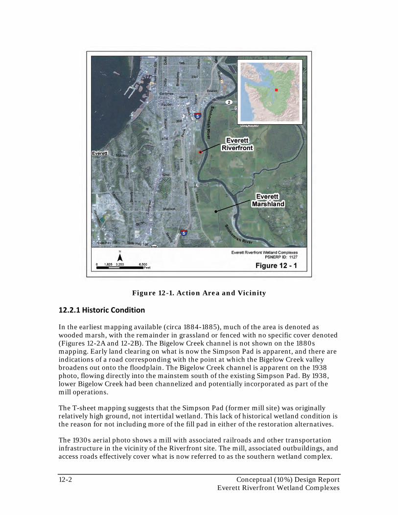
The Everett Riverfront action area is part of the Snohomish River delta in the Whidbey Subbasin of Puget Sound. The action area lies between an active railroad line (to the west) and the Snohomish River mainstem (to the east), east of I-5 in Everett. This land is within the Snohomish River floodplain in the upper portion of the estuary. Bigelow Creek drains the hillside to the west of the action area via several large freshwater wetlands. The action area wraps around the Simpson Pad, the fill pad associated with the former (now abandoned) Simpson lumber mill. Private developers intend to develop the 119-acre pad site with the support of the City of Everett planning department. The City’s Master Plan describes the planned restoration and development of the Riverfront area (MacLeod Reckord 2009). The action area is shown in Figure 12-1.
12-2 Conceptual (10%) Design Report Everett Riverfront Wetland Complexes
Figure 12-1. Action Area and Vicinity
12.2.1 Historic Condition
In the earliest mapping available (circa 1884-1885), much of the area is denoted as wooded marsh, with the remainder in grassland or fenced with no specific cover denoted (Figures 12-2A and 12-2B). The Bigelow Creek channel is not shown on the 1880s mapping. Early land clearing on what is now the Simpson Pad is apparent, and there are indications of a road corresponding with the point at which the Bigelow Creek valley broadens out onto the floodplain. The Bigelow Creek channel is apparent on the 1938 photo, flowing directly into the mainstem south of the existing Simpson Pad. By 1938, lower Bigelow Creek had been channelized and potentially incorporated as part of the mill operations.
The T-sheet mapping suggests that the Simpson Pad (former mill site) was originally relatively high ground, not intertidal wetland. This lack of historical wetland condition is the reason for not including more of the fill pad in either of the restoration alternatives.
The 1930s aerial photo shows a mill with associated railroads and other transportation infrastructure in the vicinity of the Riverfront site. The mill, associated outbuildings, and access roads effectively cover what is now referred to as the southern wetland complex.
Conceptual (10%) Design Report 12-3 Everett Riverfront Wetland Complexes
The western wetland complex is apparent in the 1938 photo and appears generally similar to today’s conditions in terms of layout and vegetation. A northern wetland complex is also apparent in the 1938 photograph. A linear ditch had been excavated by that time through the center of the wetland (and is still present).
Fill and active drainage are more apparent in the southern portion of the northern wetland complex. The rail line along the edge of the mainstem and associated buildings are apparent by 1938. The railroad along the mainstem appears to have broken the historical connections between the river and the floodplain in this location. Levees are also apparent along the mainstem on the opposite (east) side of the river by 1938.
12.2.2 Natural Environment
The Snohomish River mainstem flows alongside the action area. Ebey Slough branches from the mainstem approximately 7,100 feet upstream of the action area. Water levels in the Snohomish River are tidally dominated, but significant freshwater inflows can override tidal signals. Salinity levels are not well understood in this reach of the river, but are not expected to support salt marsh vegetation.
There are three main wetland complexes within the Everett Riverfront action area. The northern wetland complex, north of the Simpson Pad, is an approximately 32-acre Category I wetland (according to the Department of Ecology’s rating system) that extends to the west bank of the Snohomish River. The western wetland complex, west of the Simpson Pad, is a large depression on valley alluvium alongside the railroad corridor. The southern wetland complex is a series of depressions that flow into the Snohomish River south of the Simpson Pad.
All of the wetland complexes have been altered by past land uses. Drainage to and through the wetlands has been modified with berms and artificial ditches. Historical aerial photographs indicate that portions of the complexes were cleared and graded, and portions were used as process water facilities. Non-native weed species, particularly reed canarygrass, dominate significant portions of the wetland complexes today.
The Simpson Pad is currently grassland. The surrounding wetland complexes are a mixture of open water, emergent, scrub-shrub, and forested vegetation communities.
Three listed fish species occur within the lower Snohomish River Estuary: Chinook, steelhead, and bull trout (the lower Snohomish River is listed as critical habitat for both Chinook salmon and bull trout). Fish currently have access to Bigelow Creek within the action area, extending up to a culvert under the BNSF railroad tracks. Chinook use of the mainstem channel is limited mainly to upstream migration of adults and downstream migration of juveniles, with some year-round rearing. The majority of the action area is within the 100-year (1% annual chance) floodplain of the Snohomish River. The northern wetland complex is mapped as within the floodway. The river inundates the wetland complexes and flows around the west side of the Simpson Pad during flood events (FEMA DFIRM 2010).
12.2.3 Human Environment
The Everett Riverfront action area has supported a number of industries and land uses since the 1850s. Most notable was the paper mill that operated on the site from the late 1800s to the 1970s (HistoryLink.org). A number of support industries to the mill
12-4 Conceptual (10%) Design Report Everett Riverfront Wetland Complexes
occurred within the action area, including blacksmith shops and railroads. After the mill closed, the site was used as a refuse transfer station and animal shelter (MacLeod Reckord 2009).
The BNSF railroad mainline runs along the southwest edge of the action area. A northeast-trending abandoned spur line now used as a trail corridor forms the remainder of the west action area boundary. The trail corridor links municipal parks located north and south of the Everett Riverfront area. Another abandoned railroad embankment follows the riverbank for the majority of the action area; the railroad grade still exists in places but the track has been removed. Several gravel access roads, active rail lines, and a paved trail also cross the action area. The riverbank through much of the action area has been modified with wooden piers and riprap armoring.
South of the action area, WSDOT has recently installed a series of stormwater treatment wetlands that provide water quality treatment for runoff from I-5. These ponds discharge to the mainstem Snohomish River south of the southern wetland complex.
12.3 Restoration Design Concept
12.3.1 Restoration Overview and Key Design Assumptions
The restoration alternatives are illustrated in Figures 12-3 through 12-6. The overall intent of the Everett Riverfront restoration action is to provide greater connectivity between the mainstem Snohomish River and the large freshwater wetland complexes on the site. The full restoration alternative entails work within the northern, western, and southern wetland complexes, and realignment of Bigelow Creek. The key design elements of the full restoration alternative include (Figure 12-3):
• Excavating small distributary channels and installing new openings to the main river within the northern wetland complex.
• Removing a portion of the Simpson Pad.
• Excavating a new channel alignment for Bigelow Creek.
• Restoring intertidal elevations by removing fill and a culvert within the southern wetland complex.
• Installing compost planting areas within the western wetland complex.
• Removing existing wooden bulkheads and piles along the west bank of the main Snohomish River channel.
The partial restoration alternative, which is designed to be more consistent with the proponent’s planned restoration activities in this location, only addresses the northern wetland complex (Figure 12-4). The partial restoration alternative includes new distributary channels, improved connectivity to the main river channel, and revegetation to promote establishment of complex freshwater tidal wetlands.
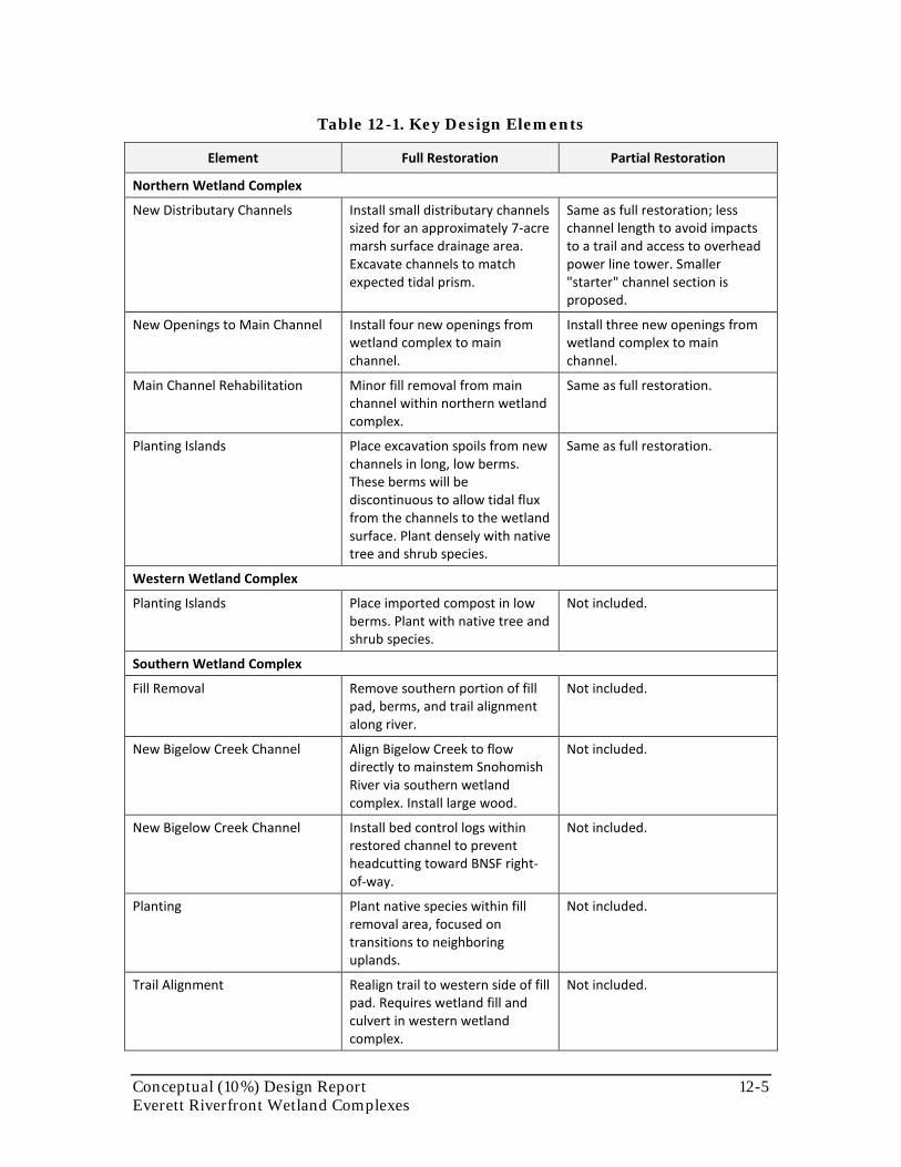
Table 12-1 summarizes the key design elements associated with full and partial restoration alternatives.
Conceptual (10%) Design Report 12-5 Everett Riverfront Wetland Complexes
Table 12-1. Key Design Elements
Element Full Restoration Partial Restoration
Northern Wetland Complex
New Distributary Channels Install small distributary channels sized for an approximately 7-acre marsh surface drainage area. Excavate channels to match expected tidal prism.
Same as full restoration; less channel length to avoid impacts to a trail and access to overhead power line tower. Smaller "starter" channel section is proposed.
New Openings to Main Channel Install four new openings from wetland complex to main channel.
Install three new openings from wetland complex to main channel.
Main Channel Rehabilitation Minor fill removal from main channel within northern wetland complex.
Same as full restoration.
Planting Islands Place excavation spoils from new channels in long, low berms. These berms will be discontinuous to allow tidal flux from the channels to the wetland surface. Plant densely with native tree and shrub species.
Same as full restoration.
Western Wetland Complex
Planting Islands
Place imported compost in low berms. Plant with native tree and shrub species.
Not included.
Southern Wetland Complex
Fill Removal Remove southern portion of fill pad, berms, and trail alignment along river.
Not included.
New Bigelow Creek Channel Align Bigelow Creek to flow directly to mainstem Snohomish River via southern wetland complex. Install large wood.
Not included.
New Bigelow Creek Channel Install bed control logs within restored channel to prevent headcutting toward BNSF right-of-way.
Not included.
Planting Plant native species within fill removal area, focused on transitions to neighboring uplands.
Not included.
Trail Alignment Realign trail to western side of fill pad. Requires wetland fill and culvert in western wetland complex.
Not included.
12-6 Conceptual (10%) Design Report Everett Riverfront Wetland Complexes
12.3.2 Restoration Features – Primary Process-Based Management Measures
Armor Removal/Modification
Approximately 5,020 LF of discontinuous wooden bulkhead on the mainstem Snohomish River would be removed in the full restoration alternative (Figure 12-3). A portion of the bulkhead and pilings (approximately 2,439 LF along the northern wetland complex) would be removed in the partial restoration alternative (Figure 12-4).
Berm or Dike Removal/Modification - NA
Channel Rehabilitation/Creation
With both restoration alternatives, a system of distributary channels will be installed in the northern wetland complex (Figures 12-3 and 12-4). These channels will increase tidal flux through the wetland complex. Currently tides only enter the lower portion of the straightened main channel. The new system of channels would allow natural fluvial processes to operate, better connecting the wetland with the mainstem channel. The proposed channels in the full restoration alternative were developed to drain approximately equal portions of the wetland complex, using the regional regressions included in the Applied Geomorphology Guidelines (Appendix C). This approach likely results in an overestimate of channel size, since much of the northern wetland complex is higher than MHHW, limiting tidal flux through the channel system.
The northern wetland complex channel system will be installed in both restoration alternatives, and in generally the same alignment. The full restoration alternative includes overexcavated channels, assuming that sedimentation will occur (Figure 12-5). The partial restoration alternative (Figure 12-6) includes one less channel opening and less new channel length at the southern end of the wetland complex. Eliminating this opening allows an existing trail to remain, and retains an existing maintenance access to a BPA overhead power line. The partial restoration alternative also includes a smaller initial channel section to serve as starter channels. This approach acknowledges the likely overestimate of channel size resulting from the regional regressions and minimizes excavation quantities as well as overall disturbance to the existing wetland system.
In the full restoration alternative, the Bigelow Creek channel will be restored and realigned to flow through the southern wetland complex (Figure 12-5). Currently, Bigelow Creek flows through linear ditches with no shade or natural morphology along the railroad right-of-way as it flows north to the mainstem. The realigned creek will flow directly east to the Snohomish River mainstem through what will be an intertidal area (see the topography restoration described below). The restored Bigelow Creek alignment will generally follow an existing overflow route to the river that includes a corrugated metal pipe with flap gate. This culvert and other fill will be removed to allow a free-flowing creek mouth.
Large wood, including bed control logs, will be included along the restored Bigelow Creek channel. The bed control logs will be placed to avoid channel headcutting back toward the BNSF right-of-way.
None of the work in the southern wetland complex will occur in the partial restoration alternative.
Conceptual (10%) Design Report 12-7 Everett Riverfront Wetland Complexes
Groin Removal/Modification - NA
Hydraulic Modification
In the full restoration alternative, a culvert in the southern wetland complex would be removed, and Bigelow Creek would be rerouted to avoid several other culvert crossings (Figure 12-3).
Overwater Structure Removal - NA
Topography Restoration
In the full restoration alternative, fill will be removed from a portion of the Simpson Pad directly north of the southern wetland complex. This will allow restoration of intertidal wetland at the restored mouth of Bigelow Creek, and provide greater freshwater tidal wetland area adjacent to the mainstem. This will require excavation depths of up to 14 feet, with additional depth required along the Bigelow Creek channel (Figure 12-5).
In the northern wetland complex, spoils from the channel excavations will be placed in low berms along the new channels for both alternatives (Figures 12-5 and 12-6). These berms will be planted with native shrub and tree species to provide greater complexity for the wetland system and shade for the channels.
In the full restoration alternative, a similar measure will be taken for the western wetland complex. Compost berms will be imported, placed, and densely planted. The current wetland is dominated by reed canarygrass and cattails, so these planting islands are intended to increase complexity.
12.3.3 Restoration Features – Additional Management Measures
Beach Nourishment - NA
Contaminant Removal/Remediation
Contaminated soils are likely to occur in much of the action area, particularly the southern wetland complex, as it was the former location of the mill and several subsidiary facilities including the blacksmith shop. Part of the topographic restoration would include the excavation and removal of these contaminants.
Debris Removal - NA
Invasive Species Control
Invasive species on the site include reed canarygrass and Himalayan blackberry. A long-term goal of the distributary channel system and associated berms in the northern wetland complex is reduced dominance by reed canarygrass. The dense plantings of shrubs and trees will eventually provide greater shade, favoring other plant species.
For the full restoration alternative, excavations to intertidal elevations would occur within the southern wetland complex. The depths of tidal water in these areas should allow for colonization by freshwater intertidal species, rather than reed canarygrass.
12-8 Conceptual (10%) Design Report Everett Riverfront Wetland Complexes
Large Wood Placement
Salvaged and imported large wood from site clearing will be placed on the surface of the northern wetland complex, and along the mainstem where armor has been removed in both the full and partial restoration alternatives (Figures 12-3 and 12-4). Within the wetlands, downed wood is intended to support colonization by native shrub and tree species. Large wood will also be placed along the mainstem where the wooden bulkhead is removed to provide edge habitat along the mainstem. Wood quantities are based on Fox and Bolton (2007), using the median density along channel length.
Physical Exclusion - NA
Pollution Control - NA
Revegetation
Plantings of native vegetation communities are proposed in a number of locations. In the northern wetland complex, the berms created from channel excavation spoils will be densely planted with native shrub species in both the full and partial restoration alternatives (Figures 12-3 and 12-4). Channel excavation quantities will be smaller in the partial restoration alternative, so the planting area will be similarly reduced.
In the western wetland complex for the full restoration alternative, installed compost berms will be densely planted with native shrub species to provide additional vertical strata and reduce the dominance of non-native, invasive weed species.
In the full restoration alternative, buffer and intertidal plantings will occur along the restored channel of Bigelow Creek. These will include freshwater tidal marsh emergent species.
Reintroduction of Native Animals - NA
Substrate Modification - NA
Species Habitat Enhancement - NA
12.3.4 Restoration Features – Other
In the full restoration alternative, an existing trail (Lowell Riverfront Trail) that runs along the riverbank from Lowell Riverfront Park to the northern wetland complex would be rerouted further west onto the Simpson Pad. The existing trail alignment would interfere with the bank sloping needed to allow for armor removal, and would require a substantial bridge over the restored Bigelow Creek area. The existing trail alignment would also interfere with one of the proposed distributary channels and new openings in the northern wetland complex.
In the partial restoration alternative, the trail could remain in its current alignment.
12.3.5 Land Requirements
Most of the action area is owned by the City of Everett and the remainder is privately held. The partial restoration alternative has been developed to stay within City property.
Conceptual (10%) Design Report 12-9 Everett Riverfront Wetland Complexes
The full restoration alternative would require acquisition of a portion of the Simpson Pad to allow for greater intertidal area at the southern wetland complex.
The full restoration alternative would also require construction easements with BNSF Railway at the tie-in point to the existing Bigelow Creek alignment. Bigelow Creek flows below the BNSF rail line and along railroad right-of-way. The proposed alignment would require earthwork within the right-of-way to connect the new channel and plug the existing ditch.
12.3.6 Design Considerations
The potential for contamination exists throughout the site, but especially in the western and southern wetland complexes, given the historical land uses. There is a restrictive covenant on the western wetland complex that limits potential excavation and increases in flow velocity. A former landfill adjacent to the action area has an active remediation project designed to prevent groundwater flow toward the river. These factors have influenced the design to avoid all excavation in the western wetland complex, and minimize excavation within the northern wetland complex. Rerouting Bigelow Creek to the south would avoid having the creek interact with these areas, potentially reducing contaminant loading to the mainstem.
12.3.7 Construction Considerations
In the northern wetland complex, construction access to the channel excavations will be limited by very soft, saturated soils. It is anticipated that mats and low-ground-pressure equipment will be required to complete this work. Temporary berms or inflatable bladders at the new channel openings may be required to protect the work area during channel excavation and berm placement. The access considerations for excavation will require greater time for the channel excavation within the northern wetland complex, likely requiring 6 to 8 weeks to fully implement.
In the western wetland complex, the compost berms are anticipated to be blown in place, with no machine access to the wetland. Plantings would occur with hand labor only.
In the southern wetland complex, there is suitable access via gravel roads. Access can be developed that avoids crossing the BNSF rail lines. Excavations would need to be sequenced to complete the majority of fill removal prior to allowing full tidal inundation. The extent of fill removal will extend into saturated soils, so dewatering of excavation spoils would likely be necessary prior to offsite haul or placement. This will require a local stockpile. If the restoration occurs before site development, the Simpson Pad could be used for dewatering.
12.4 Extent of Stressor Removal
Table 12-2 describes the amount of stressors to be removed with this action.
12-10 Conceptual (10%) Design Report Everett Riverfront Wetland Complexes
Table 12-2. Stressor Removal
Stressor Full Restoration Partial Restoration
Tidal Barrier (LF) 550 LF along southern wetland complex, and new openings along northern wetland complex
150 LF along new openings along northern wetland complex
Fill (acres) 9.8 acres, primarily in southern wetland complex, and new openings in northern wetland complex
0.7 acres, new openings in the northern wetland complex
Armor (LF) 5,020 2,439
12.5 Expected Evolution of the Action Area
In the northern wetland complex, the goal of the new system of distributary channels is to increase tidal flux throughout the wetland area. This channel system is anticipated to be dynamic, and the excavated channels are intended to be a starting point for the formation of a self-sustaining channel system. It is likely that some channels will become blocked via beaver dams or sedimentation. It is expected that tidal flow would be transferred to other distributary channels, or new channels would form. The rate of channel development would depend on the flooding pattern and sediment loading from the mainstem. The excavation spoils berms would develop shrub and forest structure over time, increasing shade and habitat complexity within the wetland.
In the full restoration alternative, the channels will be excavated to larger dimensions to match expected tidal flux, so less initial adjustment is expected. In the partial restoration alternative, the channels will be excavated as starter channels, with a much smaller cross sectional area. Therefore, more substantial initial channel erosion is expected for this alternative.
In the southern wetland complex, the channel is expected to develop a stable profile to meet the mainstem. This area is expected to be net aggradational, but log and rock controls will be installed to prevent headcutting that might destabilize the railroad; the opening is designed to be wide enough to prevent significant vertical scour. Sedimentation may occur in this area during or after flood events. After initial excavation, there will be approximately 9 acres of new freshwater intertidal wetland at the mouth of Bigelow Creek.
12.6 Uncertainties and Risks
The site’s location within the floodplain and likely channel migration zone of the Snohomish River suggests that the action area can evolve via fluvial processes. The full restoration alternative would remove shoreline armoring, which could allow for greater rates of channel migration in this location. Flooding from the mainstem also has the potential to alter the functioning of the restored systems by erosion, sedimentation, or changing wetland hydroperiods.
As noted above, the presence of contaminated soils is likely throughout the site, especially in the southern wetland complex.
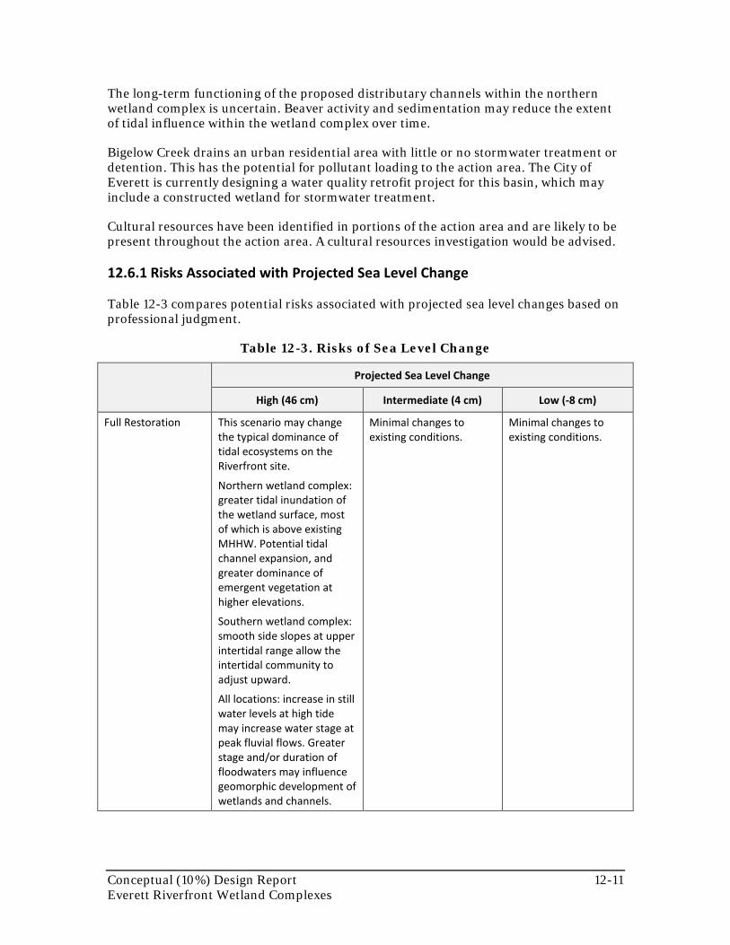
Conceptual (10%) Design Report 12-11 Everett Riverfront Wetland Complexes
The long-term functioning of the proposed distributary channels within the northern wetland complex is uncertain. Beaver activity and sedimentation may reduce the extent of tidal influence within the wetland complex over time.
Bigelow Creek drains an urban residential area with little or no stormwater treatment or detention. This has the potential for pollutant loading to the action area. The City of Everett is currently designing a water quality retrofit project for this basin, which may include a constructed wetland for stormwater treatment.
Cultural resources have been identified in portions of the action area and are likely to be present throughout the action area. A cultural resources investigation would be advised.
12.6.1 Risks Associated with Projected Sea Level Change
Table 12-3 compares potential risks associated with projected sea level changes based on professional judgment.
Table 12-3. Risks of Sea Level Change
Projected Sea Level Change
High (46 cm) Intermediate (4 cm) Low (-8 cm)
Full Restoration This scenario may change the typical dominance of tidal ecosystems on the Riverfront site.
Northern wetland complex: greater tidal inundation of the wetland surface, most of which is above existing MHHW. Potential tidal channel expansion, and greater dominance of emergent vegetation at higher elevations.
Southern wetland complex: smooth side slopes at upper intertidal range allow the intertidal community to adjust upward.
All locations: increase in still water levels at high tide may increase water stage at peak fluvial flows. Greater stage and/or duration of floodwaters may influence geomorphic development of wetlands and channels.
Minimal changes to existing conditions.
Minimal changes to existing conditions.

12-12 Conceptual (10%) Design Report Everett Riverfront Wetland Complexes
Projected Sea Level Change
High (46 cm) Intermediate (4 cm) Low (-8 cm)
Partial Restoration This scenario may change the typical dominance of tidal ecosystems on the Riverfront site.
Northern wetland complex: greater tidal inundation of the wetland surface, most of which is above existing MHHW. Potential tidal channel expansion, and greater dominance of emergent vegetation at higher elevations.
Higher tide heights alter high fluvial flow stage.
Minimal changes to existing conditions.
Minimal changes to existing conditions.
12.7 Potential Monitoring Opportunities
Monitoring is important for evaluating restoration success. A combination of field surveys and aerial photographs would be used to document biological and physical changes to the landscape. Monitoring data can be used to refine adaptive management and corrective actions, as needed. Some of the main monitoring needs and opportunities associated with this action are summarized in Table 12-4.
Table 12-4. Monitoring Needs and Opportunities
Monitoring Parameter Key Performance
Indicator Note
Topographic Stability X
Within northern wetland complex, and in excavated intertidal area
Sediment Accretion / Erosion X Within southern wetland complex
Wood Accumulation
Soil / Substrate Conditions
Vegetation Establishment X
Effectiveness of compost and dredge spoil berms
Marsh Surface Evolution / Accretion X
Tidal Channel Cross-Section / Density X
Channel evolution in the northern wetland complex
Water Quality (contaminants)
Salinity
Shellfish Production
Extent of Invasive Species
Animal Species Richness

Conceptual (10%) Design Report 12-13 Everett Riverfront Wetland Complexes
Monitoring Parameter Key Performance
Indicator Note
Fish (salmonid) Access/Use X
Edge habitats along mainstem (ongoing elsewhere in lower Snohomish Estuary)
Forage Fish Production
Wildlife Species Use
Effectiveness of Exclusion Devices
12.8 Information Needed for Subsequent Design
This conceptual design report represents an initial step in the restoration design sequence. The design concepts described above were developed based on readily available information without the level of site-specific survey and investigation that is necessary to support subsequent design and implementation. Substantial additional information will be required at the preliminary and later design stages to confirm the design assumptions, refine quantity estimates, address property and regulatory issues, obtain stakeholder support, and fill in data gaps. The extent to which this information is collected for preliminary design (or a later design stage) will depend upon the available budget, schedule and other factors. This section attempts to define the most essential information needs for this action. Refer to the Introduction chapter for additional information.
• Property Investigation/Survey – More detailed information on parcel ownership, utility locations, and property boundary locations will be needed to finalize the design, confirm acquisition requirements, and support negotiations with property owners.
• Topographic/Bathymetric Survey –Restoration would require a topographic survey to confirm elevations and refine quantity estimates. Survey data would also be used as a baseline for pre- and post-construction modeling.
• Geotechnical Investigation – Borings are needed to assess subsurface conditions in the area proposed for intertidal excavation in the southern wetland complex.
• Cultural Resources Investigation – Surveys for archaeological and historic resources may be required for this action area. This is particularly important in areas proposed for excavation.
• Contaminant Survey – If preliminary investigations confirm that hazardous material are present in the action area, additional soil and sediment analysis may be needed.
12.9 Quantity Estimates
The quantity spreadsheets for the full and partial restoration alternatives are provided in Exhibits 12-1 and 12-2.

12-14 Conceptual (10%) Design Report Everett Riverfront Wetland Complexes
12.10 References
MacLeod Reckord, PLLC. 2009. Riverfront Development Public Amenities Master Plan – Final Draft. May. Seattle, WA. Prepared for City of Everett Engineering and Public Services Department and Parks and Recreation Department, Everett, WA.
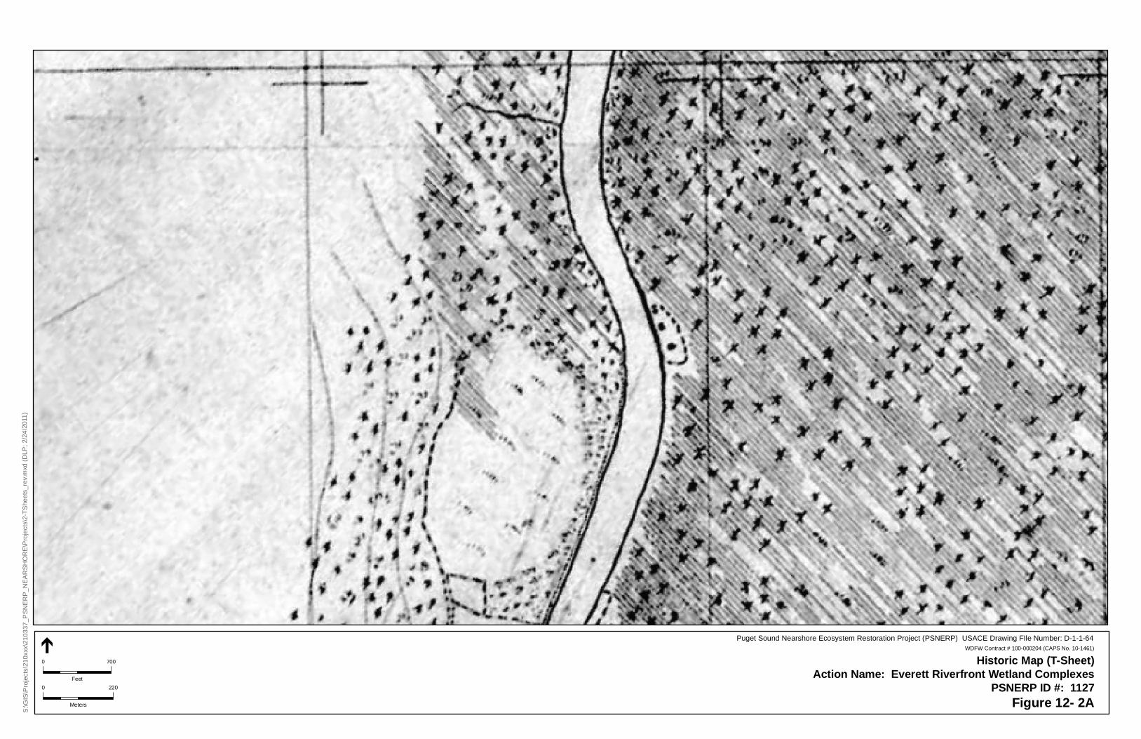
S:\G
IS\P
roje
cts\
210x
xx\2
103
37_P
SN
ER
P_N
EA
RS
HO
RE
\Pro
ject
s\2-
TS
heet
s_re
v.m
xd (
DLP
; 2/2
4/2
011)
Historic Map (T-Sheet)Action Name: Everett Riverfront Wetland Complexes
PSNERP ID #: 1127Figure 12- 2A
Puget Sound Nearshore Ecosystem Restoration Project (PSNERP) USACE Drawing FIle Number: D-1-1-64WDFW Contract # 100-000204 (CAPS No. 10-1461)
0 700
Feet
0 220
Meters
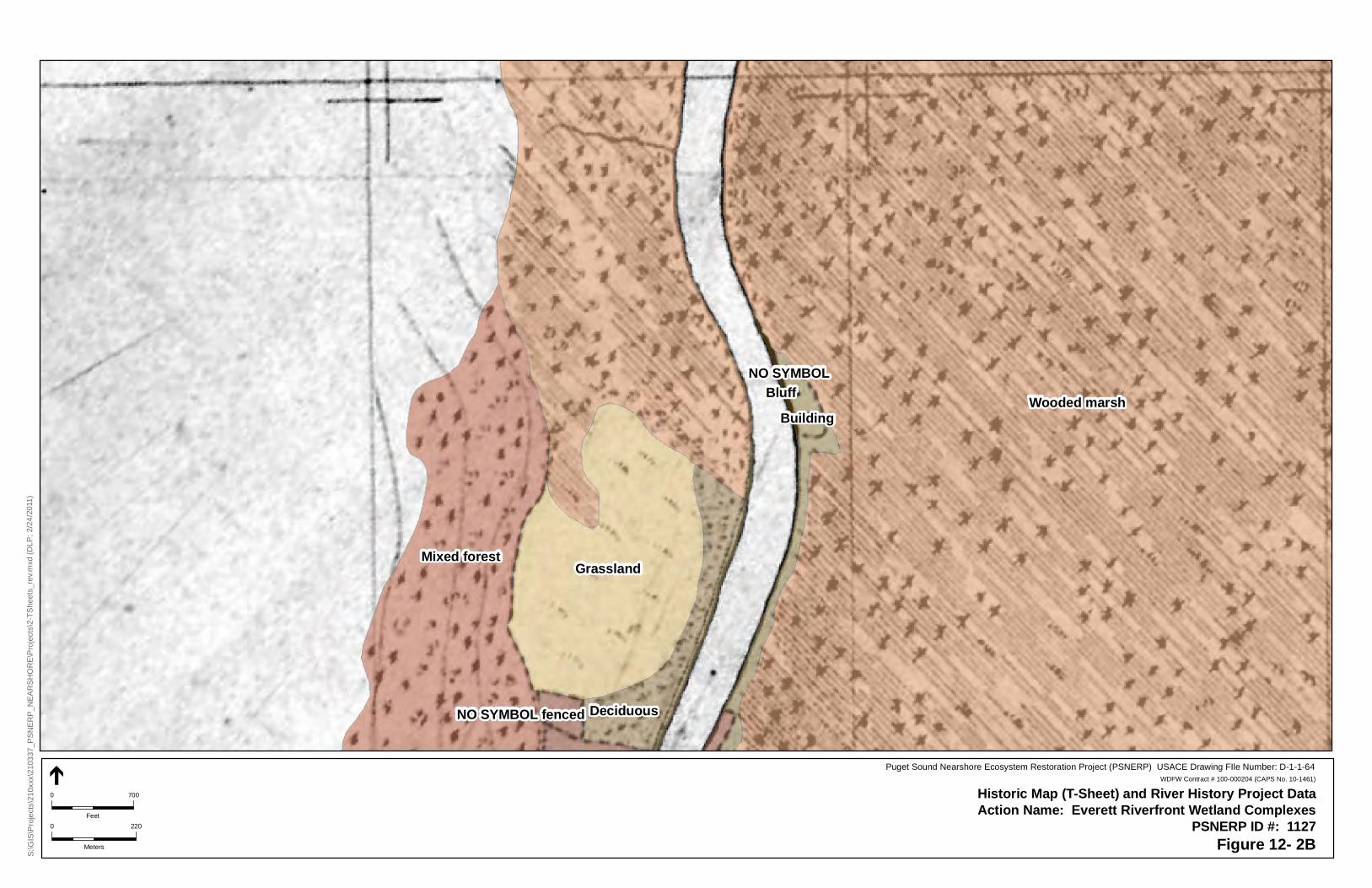
Wooded marsh
Mixed forest Grassland
Deciduous
NO SYMBOLBluff
NO SYMBOL fenced
Building
S:\G
IS\P
roje
cts\
210x
xx\2
103
37_P
SN
ER
P_N
EA
RS
HO
RE
\Pro
ject
s\2-
TS
heet
s_re
v.m
xd (
DLP
; 2/2
4/2
011)
Historic Map (T-Sheet) and River History Project DataAction Name: Everett Riverfront Wetland Complexes
PSNERP ID #: 1127Figure 12- 2B
Puget Sound Nearshore Ecosystem Restoration Project (PSNERP) USACE Drawing FIle Number: D-1-1-64WDFW Contract # 100-000204 (CAPS No. 10-1461)
0 700
Feet
0 220
Meters
óóóóóóóóóóóó
óóóóóóóóóóóóóóóóóóóóóóóó
óóóóóóóóóóóóóó
óóóóóóóóóóóóóóóóóóóóóóóóóóóóóóóóóóóóóóóóóóóóóóóóóóóóóóóó
kjI 5
S 3rd A
ve
S 4th A
ve
Junc
tion
Ave
Sm
ith A
ve
S 2n
d Ave
Acc
ess
Rd
41st St
38th St
Paine S
t
49th St SE
40th St
39th St
45th St SE
44th St SE
46th St SE
47th St SE
43rd St SE
I 5
Access R
d
Ram
p
Ram
p
38th St
Puget Sound Nearshore Ecosystem Restoration Project (PSNERP) USACE Drawing FIle Number: D-1-1-64SOURCE: PSNERP (2011); Aerial (Bing, 2009)
Lead Contractor: ESA Design Lead: ESADate: 2/28/2011
Legend
Conceptual Design PlanSite Name: Snohomish River Delta
Action Name: Everett Riverfront Wetland ComplexesPSNERP ID #:1127
Full Restoration
WDFW Contract # 100-000204 (CAPS No. 10-1461)
EXCAVATE DISTRIBUTARY CHANNEL SYSTEMEXCAVATION LOWLAND 12,500 CYCHANNEL CREATION 88,150 SF
PLACE COMPOST BERMS, PLANT DENSELY WITH NATIVE TREES AND SHRUBSPLANTING = 0.52 ACRES
REMOVE HISTORIC FILL, CULVERT, AND RESTORE BIGELOW CREEK CHANNELEXCAVATION LOWLAND130.000 CYCHANNEL REHABILITATION30,800 SF
PLACE DREDGE SPOILS AS SHALLOW BERMS, DENSELY PLANTED WITH NATIVE TREES AND SHRUBSHAUL, PLACE, COMPACT = 12,630 CYPLANTING = 7.5 ACRES
kj Large Wood Placement
Culvert
Proposed Tide MHHW
Existing Tide MHHW
Bulkheads
Channel Rehab/Creation
Side Cast
óóóó Trails
Haul, Place, Compact
Planting
Required Project Lands
Excavation - Lowland
Excavation - Upland
REMOVE WOODEN PILINGS, PLANT NATIVE RIPARIAN COMMUNITYBULKHEAD5,020 LFPLANTING2.7 ACRES
Pa
th:
\\es
a_
sf_
2k\
esa
\GIS
\GIS
\Pro
ject
s\2
10
xxx\
21
03
37_
PS
NE
RP
_N
EA
RS
HO
RE
\Dat
a\W
ork
ing
\ES
A_
act
ions
\11
27_
Riv
erf
ront
_fu
ll_re
v1.m
xd (
SW
; 1
2/1
7/1
0)
AA
'
B
B'
A A '
Section Lines
Snohom
ish River
!"̀$
!"̀$
PLACE LARGE WOOD ALONG ARMOR REMOVAL AREA5,020 LF
RELOCATE PORTION OF TRAIL AWAY FROM RIVERBANK
NORTHERN WETLAND COMPLEX
WESTERN WETLAND COMPLEX
SOUTHERN WETLAND COMPLEX
SIMPSON PAD
CC
'
0 240
FeetNorth
Figure 12-3
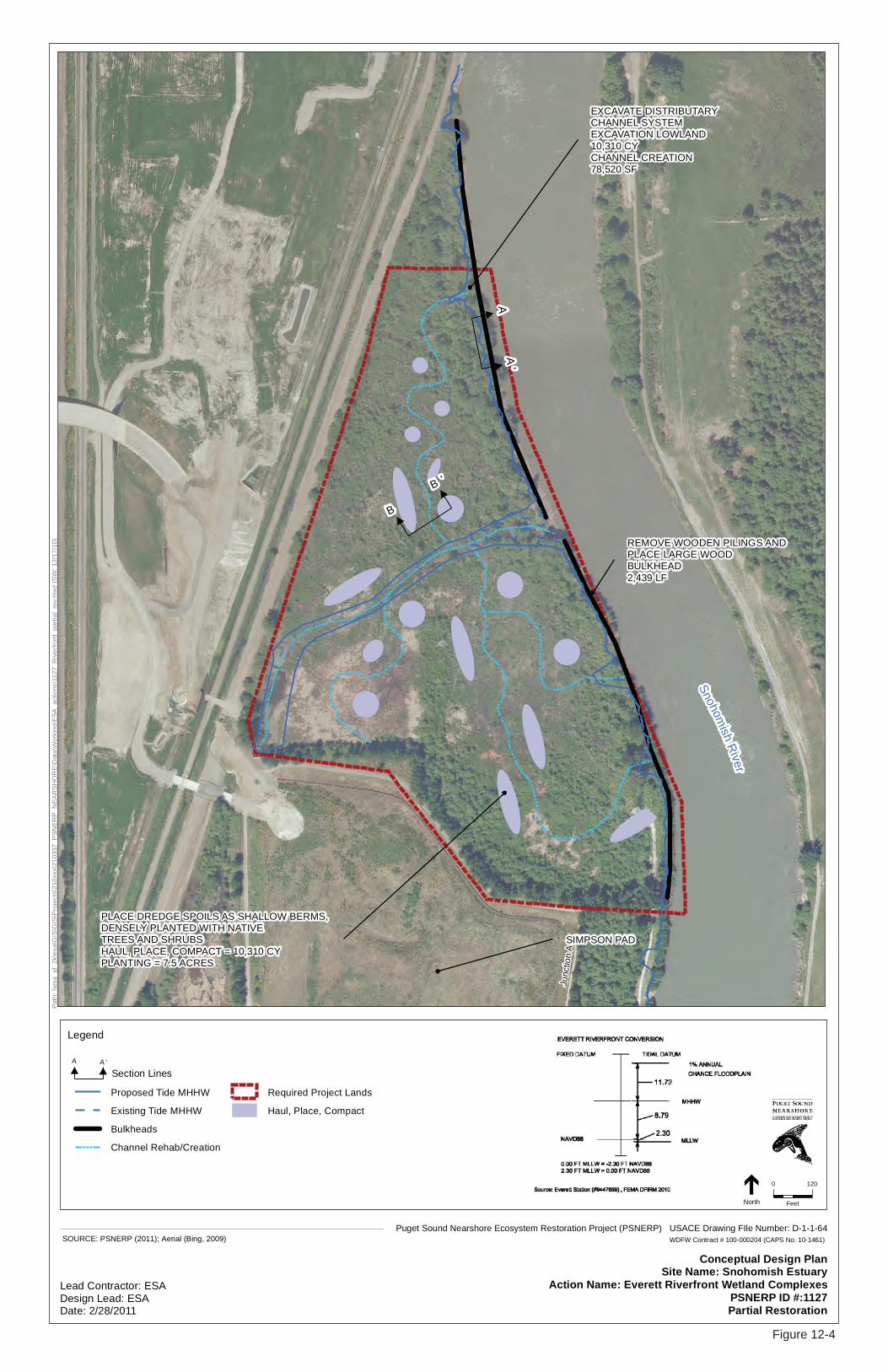
Junc
tion
Ave
Puget Sound Nearshore Ecosystem Restoration Project (PSNERP) USACE Drawing FIle Number: D-1-1-64SOURCE: PSNERP (2011); Aerial (Bing, 2009)
Lead Contractor: ESADesign Lead: ESADate: 2/28/2011
Legend
Conceptual Design PlanSite Name: Snohomish Estuary
Action Name: Everett Riverfront Wetland ComplexesPSNERP ID #:1127Partial Restoration
WDFW Contract # 100-000204 (CAPS No. 10-1461)
EXCAVATE DISTRIBUTARY CHANNEL SYSTEMEXCAVATION LOWLAND 10,310 CYCHANNEL CREATION 78,520 SF
PLACE DREDGE SPOILS AS SHALLOW BERMS, DENSELY PLANTED WITH NATIVE TREES AND SHRUBSHAUL, PLACE, COMPACT = 10,310 CYPLANTING = 7.5 ACRES
Proposed Tide MHHW
Existing Tide MHHW
Bulkheads
Channel Rehab/Creation
Required Project Lands
Haul, Place, Compact
REMOVE WOODEN PILINGS ANDPLACE LARGE WOODBULKHEAD2,439 LF
Pa
th:
\\es
a_
sf_
2k\
esa
\GIS
\GIS
\Pro
ject
s\2
10
xxx\
21
03
37_
PS
NE
RP
_N
EA
RS
HO
RE
\Dat
a\W
ork
ing
\ES
A_
act
ions
\11
27_
Riv
erf
ront
_p
art
ial_
rev.
mxd
(S
W;
12
/17
/10
)
A A '
Section Lines
AA
'
B
B '
Snohom
ish River
SIMPSON PAD
0 120
FeetNorth
Figure 12-4
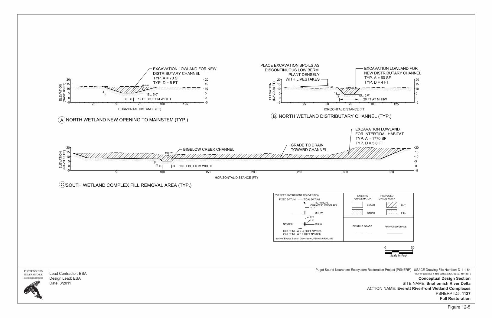
Puget Sound Nearshore Ecosystem Restoration Project (PSNERP) USACE Drawing File Number: D-1-1-64WDFW Contract # 100-000204 (CAPS No. 10-1461)
Conceptual Design SectionSITE NAME: Snohomish River Delta
ACTION NAME: Everett Riverfront Wetland ComplexesPSNERP ID#: 1127
Full Restoration
Lead Contractor: ESADesign Lead: ESADate: 3/2011
NAVD882.30
MLLW
FIXED DATUM TIDAL DATUM
0.00 FT MLLW = -2.30 FT NAVD882.30 FT MLLW = 0.00 FT NAVD88
Source: Everett Station (#9447659) , FEMA DFIRM 2010
EVERETT RIVERFRONT CONVERSION
8.79
MHHW FILL
CUT
OTHER
BEACH
EXISTING GRADE PROPOSED GRADE
PROPOSEDGRADE HATCH
EXISTINGGRADE HATCH
05
10
-50510
0 300200
SOUTH WETLAND COMPLEX FILL REMOVAL AREA (TYP.)C
100
151520 20
-5 25015050
GRADE TO DRAINTOWARD CHANNELBIGELOW CREEK CHANNEL
EXCAVATION LOWLANDFOR INTERTIDAL HABITATTYP. A = 1770 SFTYP. D = 5.8 FT
-505
10
-50510
10050
NORTH WETLAND DISTRIBUTARY CHANNEL (TYP.)B
151520 20
EXCAVATION LOWLAND FORNEW DISTRIBUTARY CHANNELTYP. A = 60 SFTYP. D = 4 FT
20 FT AT MHHWELE
VA
TIO
N(N
AV
D 8
8 FT
)
-505
10
-50510
10050
NORTH WETLAND NEW OPENING TO MAINSTEM (TYP.)A
151520 20
EXCAVATION LOWLAND FOR NEWDISTRIBUTARY CHANNELTYP. A = 70 SFTYP. D = 5 FT
12 FT BOTTOM WIDTH
PLACE EXCAVATION SPOILS ASDISCONTINUOUS LOW BERM.
PLANT DENSELYWITH LIVESTAKES
MHHW
EL. 5.0'31
21EL. 5.0'
MHHW
MHHW
350
10 FT BOTTOM WIDTH21
PLACE EXCAVATIONSPOILS AS
DISCONTINUOUSLOW BERM
ELE
VA
TIO
N(N
AV
D 8
8 FT
)
HORIZONTAL DISTANCE (FT)25 75 125 25 75 125
HORIZONTAL DISTANCE (FT)
HORIZONTAL DISTANCE (FT)
ELE
VA
TIO
N(N
AV
D 8
8 FT
)
1% ANNUAL CHANCE FLOODPLAIN
11.72
0 30
Scale in Feet
Figure 12-5
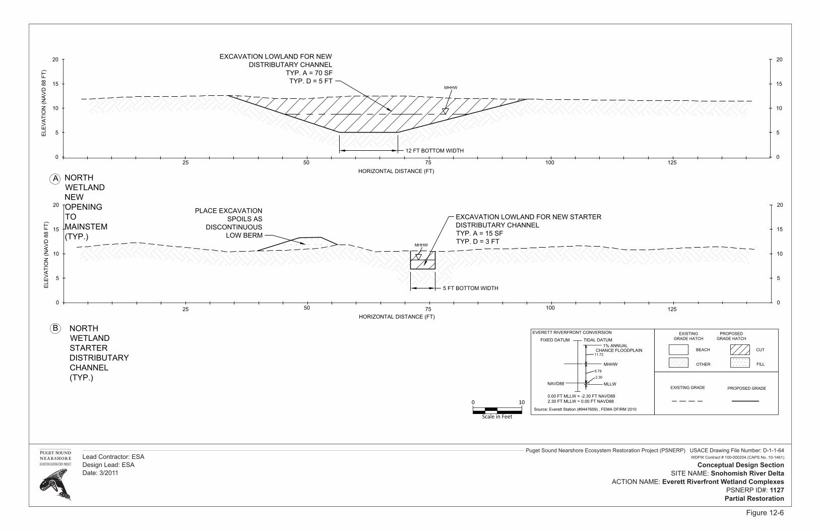
Puget Sound Nearshore Ecosystem Restoration Project (PSNERP) USACE Drawing File Number: D-1-1-64WDFW Contract # 100-000204 (CAPS No. 10-1461)
Conceptual Design SectionSITE NAME: Snohomish River Delta
ACTION NAME: Everett Riverfront Wetland ComplexesPSNERP ID#: 1127Partial Restoration
Lead Contractor: ESADesign Lead: ESADate: 3/2011
0
5
10
0
5
10
10050
NORTHWETLANDSTARTERDISTRIBUTARYCHANNEL(TYP.)
B
1515
20 20
EXCAVATION LOWLAND FOR NEW STARTERDISTRIBUTARY CHANNELTYP. A = 15 SFTYP. D = 3 FT
5 FT BOTTOM WIDTH
0
5
10
0
5
10
10050
NORTHWETLANDNEWOPENINGTOMAINSTEM(TYP.)
A
1515
20 20EXCAVATION LOWLAND FOR NEWDISTRIBUTARY CHANNEL
TYP. A = 70 SFTYP. D = 5 FT
12 FT BOTTOM WIDTH
PLACE EXCAVATIONSPOILS AS
DISCONTINUOUSLOW BERM
MHHW
MHHW
ELE
VA
TIO
N (N
AV
D 8
8 FT
)E
LEV
ATI
ON
(NA
VD
88
FT)
HORIZONTAL DISTANCE (FT)
HORIZONTAL DISTANCE (FT)
25 75 125
25 75 125
NAVD882.30
MLLW
FIXED DATUM TIDAL DATUM
0.00 FT MLLW = -2.30 FT NAVD882.30 FT MLLW = 0.00 FT NAVD88
Source: Everett Station (#9447659) , FEMA DFIRM 2010
EVERETT RIVERFRONT CONVERSION
8.79
MHHW FILL
CUT
OTHER
BEACH
EXISTING GRADE PROPOSED GRADE
PROPOSEDGRADE HATCH
EXISTINGGRADE HATCH
1% ANNUAL CHANCE FLOODPLAIN
11.72
0 10
Scale in Feet
Figure 12-6
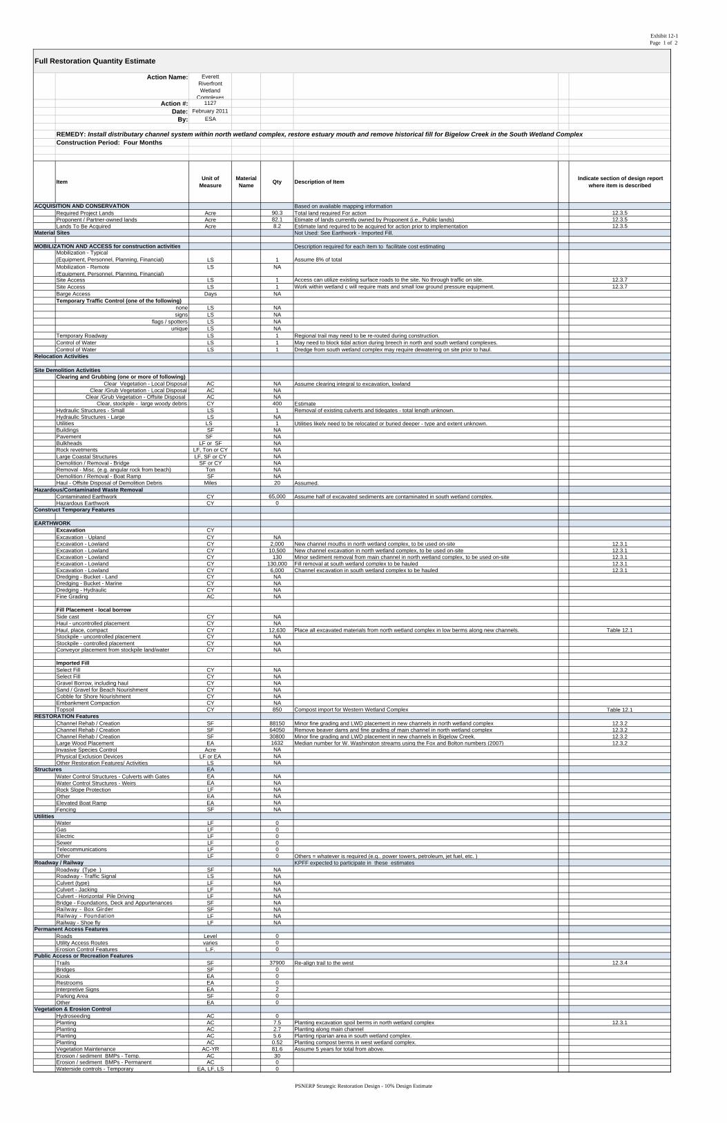
Exhibit 12-1Page 1 of 2
Action Name: Everett Riverfront Wetland
Complexes Action #: 1127
Date: February 2011
By: ESA
REMEDY: Install distributary channel system within north wetland complex, restore estuary mouth and remove historical fill for Bigelow Creek in the South Wetland ComplexConstruction Period: Four Months
ItemUnit of
MeasureMaterial Name
Qty Description of Item Indicate section of design report
where item is described
ACQUISITION AND CONSERVATION Based on available mapping informationRequired Project Lands Acre 90.3 Total land required For action 12.3.5Proponent / Partner-owned lands Acre 82.1 Etimate of lands currently owned by Proponent (i.e., Public lands) 12.3.5Lands To Be Acquired Acre 8.2 Estimate land required to be acquired for action prior to implementation 12.3.5
Material Sites Not Used: See Earthwork - Imported Fill.
MOBILIZATION AND ACCESS for construction activities Description required for each item to facilitate cost estimatingMobilization - Typical(Equipment, Personnel, Planning, Financial) LS 1 Assume 8% of totalMobilization - Remote(Equipment, Personnel, Planning, Financial)
LS NA
Site Access LS 1 Access can utilize existing surface roads to the site. No through traffic on site. 12.3.7Site Access LS 1 Work within wetland c will require mats and small low ground pressure equipment. 12.3.7Barge Access Days NATemporary Traffic Control (one of the following)
none LS NAsigns LS NA
flags / spotters LS NAunique LS NA
Temporary Roadway LS 1 Regional trail may need to be re-routed during construction.Control of Water LS 1 May need to block tidal action during breech in north and south wetland complexes.Control of Water LS 1 Dredge from south wetland complex may require dewatering on site prior to haul.
Relocation Activities
Site Demolition Activities Clearing and Grubbing (one or more of following)
Clear Vegetation - Local Disposal AC NA Assume clearing integral to excavation, lowlandClear /Grub Vegetation - Local Disposal AC NA
Clear /Grub Vegetation - Offsite Disposal AC NAClear, stockpile - large woody debris CY 400 Estimate
Hydraulic Structures - Small LS 1 Removal of existing culverts and tidegates - total length unknown.Hydraulic Structures - Large LS NAUtilities LS 1 Utilities likely need to be relocated or buried deeper - type and extent unknown.Buildings SF NAPavement SF NABulkheads LF or SF NARock revetments LF, Ton or CY NALarge Coastal Structures LF, SF or CY NADemolition / Removal - Bridge SF or CY NARemoval - Misc. (e.g. angular rock from beach) Ton NADemolition / Removal - Boat Ramp SF NAHaul - Offsite Disposal of Demolition Debris Miles 20 Assumed.
Hazardous/Contaminated Waste RemovalContaminated Earthwork CY 65,000 Assume half of excavated sediments are contaminated in south wetland complex.Hazardous Earthwork CY 0
Construct Temporary Features
EARTHWORKExcavation CYExcavation - Upland CY NAExcavation - Lowland CY 2,000 New channel mouths in north wetland complex, to be used on-site 12.3.1Excavation - Lowland CY 10,500 New channel excavation in north wetland complex, to be used on-site 12.3.1Excavation - Lowland CY 130 Minor sediment removal from main channel in north wetland complex, to be used on-site 12.3.1Excavation - Lowland CY 130,000 Fill removal at south wetland complex to be hauled 12.3.1Excavation - Lowland CY 6,000 Channel excavation in south wetland complex to be hauled 12.3.1Dredging - Bucket - Land CY NADredging - Bucket - Marine CY NADredging - Hydraulic CY NAFine Grading AC NA
Fill Placement - local borrowSide cast CY NAHaul - uncontrolled placement CY NAHaul, place, compact CY 12,630 Place all excavated materials from north wetland complex in low berms along new channels. Table 12.1Stockpile - uncontrolled placement CY NAStockpile - controlled placement CY NAConveyor placement from stockpile land/water CY NA
Imported FillSelect Fill CY NASelect Fill CY NAGravel Borrow, including haul CY NASand / Gravel for Beach Nourishment CY NACobble for Shore Nourishment CY NAEmbankment Compaction CY NATopsoil CY 850 Compost import for Western Wetland Complex Table 12.1
RESTORATION FeaturesChannel Rehab / Creation SF 88150 Minor fine grading and LWD placement in new channels in north wetland complex 12.3.2Channel Rehab / Creation SF 64050 Remove beaver dams and fine grading of main channel in north wetland complex 12.3.2Channel Rehab / Creation SF 30800 Minor fine grading and LWD placement in new channels in Bigelow Creek. 12.3.2Large Wood Placement EA 1632 Median number for W. Washington streams using the Fox and Bolton numbers (2007) 12.3.2Invasive Species Control Acre NAPhysical Exclusion Devices LF or EA NAOther Restoration Features/ Activities LS NA
Structures EAWater Control Structures - Culverts with Gates EA NAWater Control Structures - Weirs EA NARock Slope Protection LF NAOther EA NAElevated Boat Ramp EA NAFencing SF NA
Water LF 0Gas LF 0Electric LF 0Sewer LF 0Telecommunications LF 0Other LF 0 Others = whatever is required (e.g.. power towers, petroleum, jet fuel, etc. )
Roadway / Railway KPFF expected to participate in these estimatesRoadway (Type_) SF NARoadway - Traffic Signal LS NACulvert (type) LF NACulvert - Jacking LF NACulvert - Horizontal Pile Driving LF NABridge - Foundations, Deck and Appurtenances SF NARailway - Box Girder SF NARailway - Foundation LF NARailway - Shoe fly LF NA
Permanent Access FeaturesRoads Level 0Utility Access Routes varies 0Erosion Control Features L.F. 0
Public Access or Recreation FeaturesTrails SF 37900 Re-align trail to the west 12.3.4Bridges SF 0Kiosk EA 0Restrooms EA 0Interpretive Signs EA 2Parking Area SF 0Other EA 0
Vegetation & Erosion ControlHydroseeding AC 0Planting AC 7.5 Planting excavation spoil berms in north wetland complex 12.3.1Planting AC 2.7 Planting along main channelPlanting AC 5.6 Planting riparian area in south wetland complex.Planting AC 0.52 Planting compost berms in west wetland complex.Vegetation Maintenance AC-YR 81.6 Assume 5 years for total from above.Erosion / sediment BMPs - Temp. AC 30Erosion / sediment BMPs - Permanent AC 0Waterside controls - Temporary EA, LF, LS 0
Utilities
Full Restoration Quantity Estimate
PSNERP Strategic Restoration Design - 10% Design Estimate
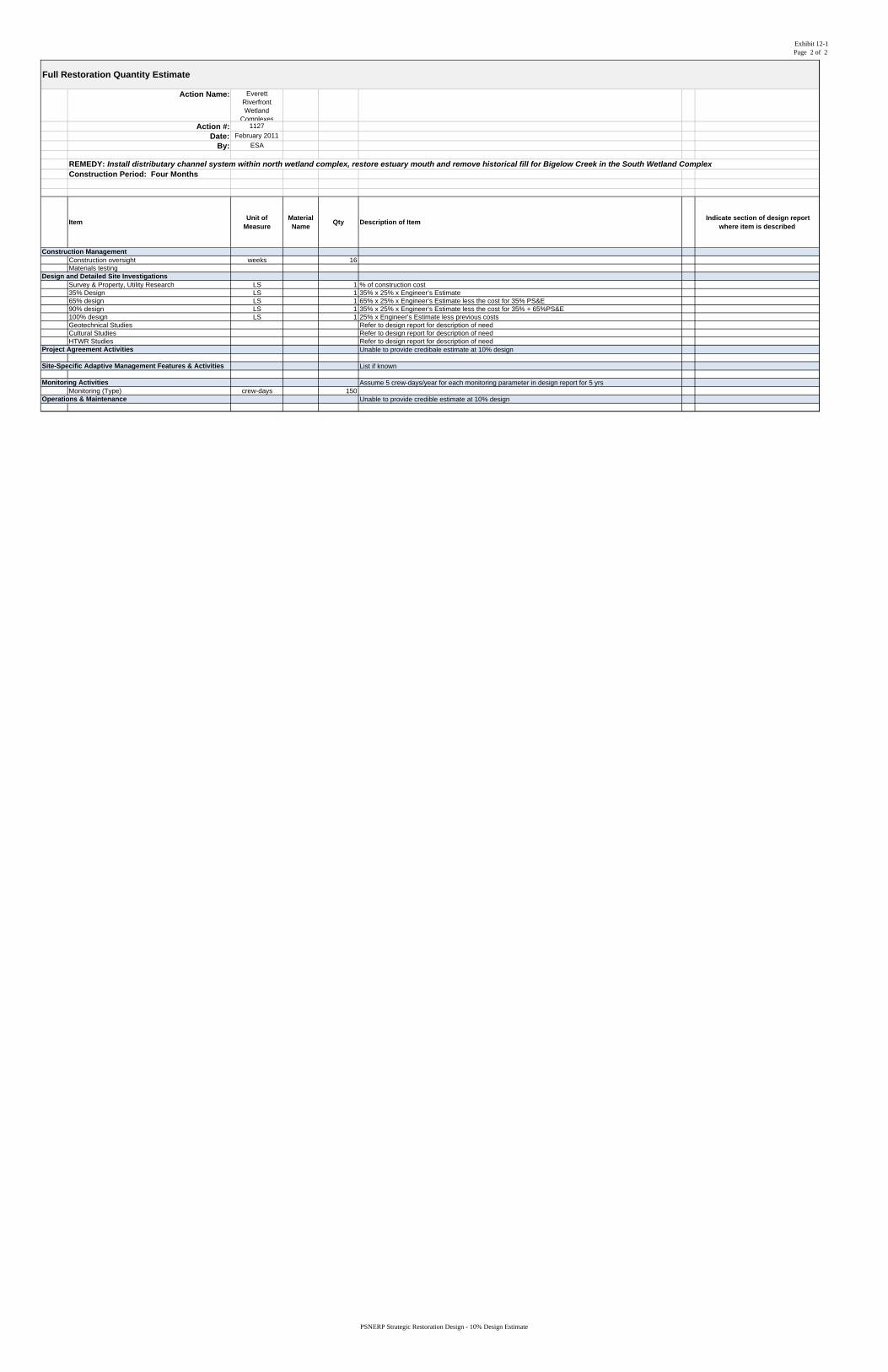
Exhibit 12-1Page 2 of 2
Action Name: Everett Riverfront Wetland
Complexes Action #: 1127
Date: February 2011
By: ESA
REMEDY: Install distributary channel system within north wetland complex, restore estuary mouth and remove historical fill for Bigelow Creek in the South Wetland ComplexConstruction Period: Four Months
ItemUnit of
MeasureMaterial Name
Qty Description of Item Indicate section of design report
where item is described
Full Restoration Quantity Estimate
Construction ManagementConstruction oversight weeks 16Materials testing
Design and Detailed Site InvestigationsSurvey & Property, Utility Research LS 1 % of construction cost35% Design LS 1 35% x 25% x Engineer’s Estimate65% design LS 1 65% x 25% x Engineer’s Estimate less the cost for 35% PS&E90% design LS 1 35% x 25% x Engineer’s Estimate less the cost for 35% + 65%PS&E100% design LS 1 25% x Engineer’s Estimate less previous costsGeotechnical Studies Refer to design report for description of needCultural Studies Refer to design report for description of needHTWR Studies Refer to design report for description of need
Project Agreement Activities Unable to provide credibale estimate at 10% design
Site-Specific Adaptive Management Features & Activities List if known
Monitoring Activities Assume 5 crew-days/year for each monitoring parameter in design report for 5 yrsMonitoring (Type) crew-days 150
Operations & Maintenance Unable to provide credible estimate at 10% design
PSNERP Strategic Restoration Design - 10% Design Estimate
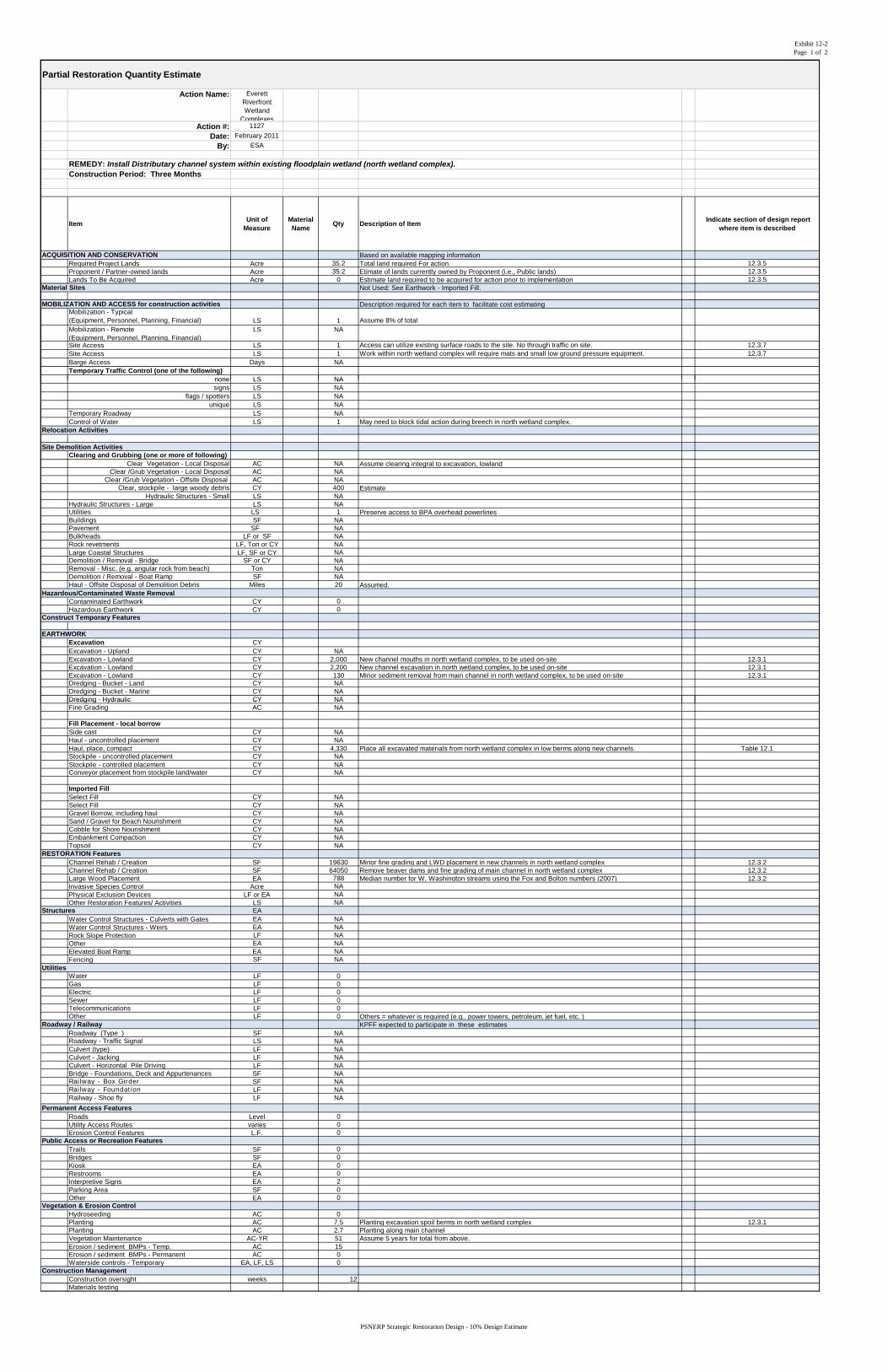
Exhibit 12-2Page 1 of 2
Action Name: Everett Riverfront Wetland
Complexes Action #: 1127
Date: February 2011
By: ESA
REMEDY: Install Distributary channel system within existing floodplain wetland (north wetland complex).Construction Period: Three Months
ItemUnit of
MeasureMaterial Name
Qty Description of Item Indicate section of design report
where item is described
ACQUISITION AND CONSERVATION Based on available mapping informationRequired Project Lands Acre 35.2 Total land required For action 12.3.5Proponent / Partner-owned lands Acre 35.2 Etimate of lands currently owned by Proponent (i.e., Public lands) 12.3.5Lands To Be Acquired Acre 0 Estimate land required to be acquired for action prior to implementation 12.3.5
Material Sites Not Used: See Earthwork - Imported Fill.
MOBILIZATION AND ACCESS for construction activities Description required for each item to facilitate cost estimatingMobilization - Typical(Equipment, Personnel, Planning, Financial) LS 1 Assume 8% of totalMobilization - Remote(Equipment, Personnel, Planning, Financial)
LS NA
Site Access LS 1 Access can utilize existing surface roads to the site. No through traffic on site. 12.3.7Site Access LS 1 Work within north wetland complex will require mats and small low ground pressure equipment. 12.3.7Barge Access Days NATemporary Traffic Control (one of the following)
none LS NA
Partial Restoration Quantity Estimate
none LS NAsigns LS NA
flags / spotters LS NAunique LS NA
Temporary Roadway LS NAControl of Water LS 1 May need to block tidal action during breech in north wetland complex.
Relocation Activities
Site Demolition Activities Clearing and Grubbing (one or more of following)
Clear Vegetation - Local Disposal AC NA Assume clearing integral to excavation, lowlandClear /Grub Vegetation - Local Disposal AC NA
Clear /Grub Vegetation - Offsite Disposal AC NAClear, stockpile - large woody debris CY 400 Estimate
Hydraulic Structures - Small LS NAHydraulic Structures - Large LS NAUtilities LS 1 Preserve access to BPA overhead powerlinesBuildings SF NAPavement SF NABulkheads LF or SF NARock revetments LF, Ton or CY NALarge Coastal Structures LF, SF or CY NADemolition / Removal - Bridge SF or CY NARemoval - Misc. (e.g. angular rock from beach) Ton NADemolition / Removal - Boat Ramp SF NAHaul - Offsite Disposal of Demolition Debris Miles 20 Assumed.
Hazardous/Contaminated Waste RemovalContaminated Earthwork CY 0Hazardous Earthwork CY 0
Construct Temporary Features
EARTHWORKExcavation CYExcavation - Upland CY NAExcavation - Lowland CY 2,000 New channel mouths in north wetland complex, to be used on-site 12.3.1Excavation - Lowland CY 2,200 New channel excavation in north wetland complex, to be used on-site 12.3.1Excavation - Lowland CY 130 Minor sediment removal from main channel in north wetland complex, to be used on-site 12.3.1Dredging - Bucket - Land CY NADredging - Bucket - Marine CY NADredging - Hydraulic CY NADredging Hydraulic CY NAFine Grading AC NA
Fill Placement - local borrowSide cast CY NAHaul - uncontrolled placement CY NAHaul, place, compact CY 4,330 Place all excavated materials from north wetland complex in low berms along new channels. Table 12.1Stockpile - uncontrolled placement CY NAStockpile - controlled placement CY NAConveyor placement from stockpile land/water CY NA
Imported FillSelect Fill CY NASelect Fill CY NAGravel Borrow, including haul CY NASand / Gravel for Beach Nourishment CY NACobble for Shore Nourishment CY NAEmbankment Compaction CY NATopsoil CY NA
RESTORATION FeaturesChannel Rehab / Creation SF 19630 Minor fine grading and LWD placement in new channels in north wetland complex 12.3.2Channel Rehab / Creation SF 64050 Remove beaver dams and fine grading of main channel in north wetland complex 12.3.2Large Wood Placement EA 788 Median number for W. Washington streams using the Fox and Bolton numbers (2007) 12.3.2Invasive Species Control Acre NAPhysical Exclusion Devices LF or EA NAOther Restoration Features/ Activities LS NA
Structures EAWater Control Structures - Culverts with Gates EA NAWater Control Structures - Weirs EA NARock Slope Protection LF NAOther EA NAElevated Boat Ramp EA NAFencing SF NA
UtilitiesWater LF 0Gas LF 0Electric LF 0Sewer LF 0Telecommunications LF 0Other LF 0 Others = whatever is required (e.g.. power towers, petroleum, jet fuel, etc. )
R d / R il KPFF t d t ti i t i th ti tRoadway / Railway KPFF expected to participate in these estimatesRoadway (Type_) SF NARoadway - Traffic Signal LS NACulvert (type) LF NACulvert - Jacking LF NACulvert - Horizontal Pile Driving LF NABridge - Foundations, Deck and Appurtenances SF NARailway - Box Girder SF NARailway - Foundation LF NARailway - Shoe fly LF NA
Permanent Access FeaturesRoads Level 0Utility Access Routes varies 0Erosion Control Features L.F. 0
Public Access or Recreation FeaturesTrails SF 0Bridges SF 0Kiosk EA 0Restrooms EA 0Interpretive Signs EA 2Parking Area SF 0Other EA 0
Vegetation & Erosion ControlHydroseeding AC 0Planting AC 7.5 Planting excavation spoil berms in north wetland complex 12.3.1Planting AC 2.7 Planting along main channelVegetation Maintenance AC-YR 51 Assume 5 years for total from above.Erosion / sediment BMPs - Temp. AC 15Erosion / sediment BMPs - Permanent AC 0Waterside controls - Temporary EA, LF, LS 0
Construction ManagementConstruction oversight weeks 12Materials testing
PSNERP Strategic Restoration Design - 10% Design Estimate
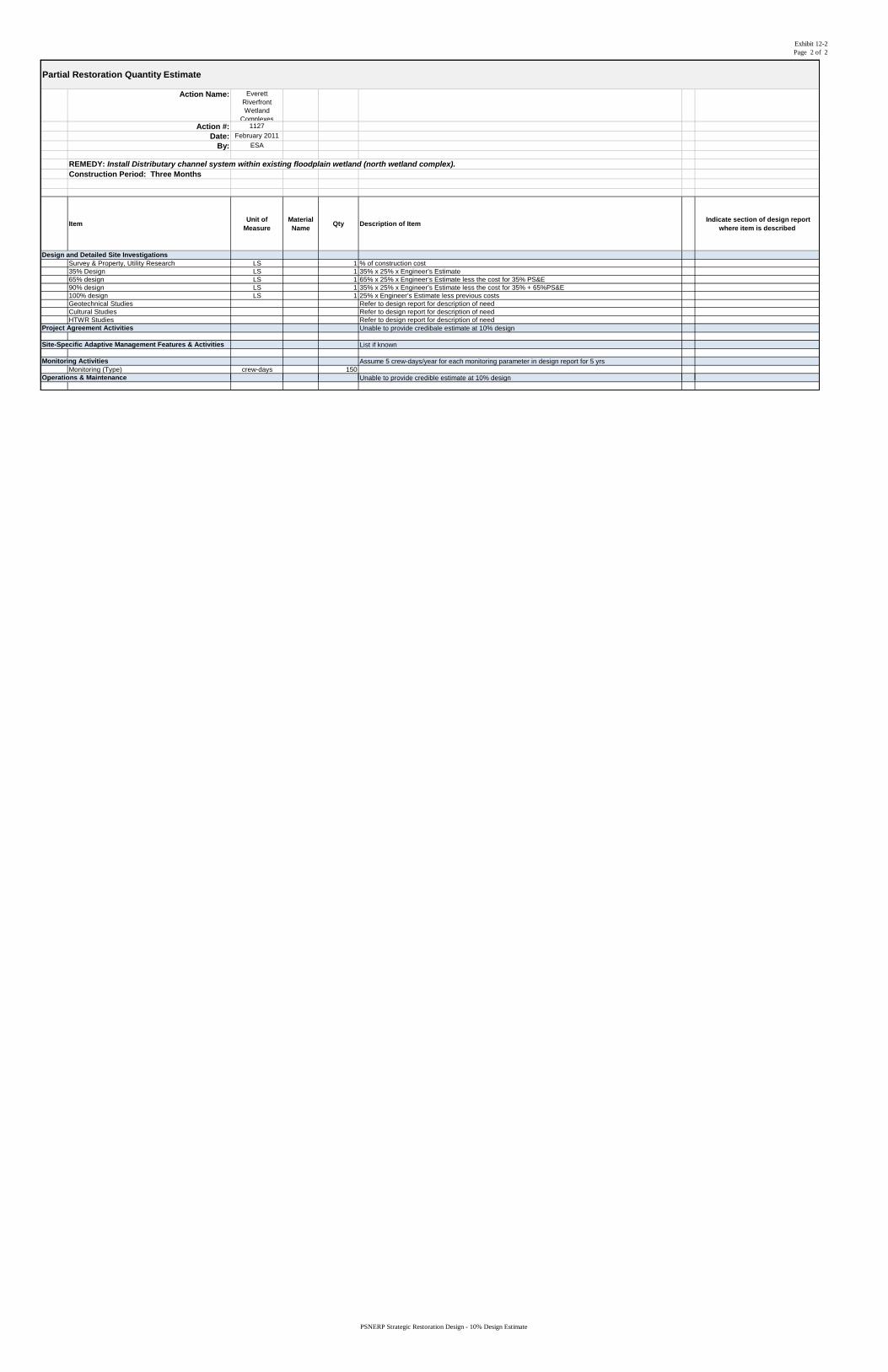
Exhibit 12-2Page 2 of 2
Action Name: Everett Riverfront Wetland
Complexes Action #: 1127
Date: February 2011
By: ESA
REMEDY: Install Distributary channel system within existing floodplain wetland (north wetland complex).Construction Period: Three Months
ItemUnit of
MeasureMaterial Name
Qty Description of Item Indicate section of design report
where item is described
Partial Restoration Quantity Estimate
Design and Detailed Site InvestigationsSurvey & Property, Utility Research LS 1 % of construction cost35% Design LS 1 35% x 25% x Engineer’s Estimate65% design LS 1 65% x 25% x Engineer’s Estimate less the cost for 35% PS&E90% design LS 1 35% x 25% x Engineer’s Estimate less the cost for 35% + 65%PS&E100% design LS 1 25% x Engineer’s Estimate less previous costsGeotechnical Studies Refer to design report for description of needCultural Studies Refer to design report for description of needHTWR Studies Refer to design report for description of need
Project Agreement Activities Unable to provide credibale estimate at 10% design
Site-Specific Adaptive Management Features & Activities List if known
Monitoring Activities Assume 5 crew-days/year for each monitoring parameter in design report for 5 yrsMonitoring (Type) crew-days 150
Operations & Maintenance Unable to provide credible estimate at 10% design p Unable to provide credible estimate at 10% design
PSNERP Strategic Restoration Design - 10% Design Estimate