puff erfedern maße und technische daten - grueber.de · werkstoffe die aufgeführten werkstoffe...
TRANSCRIPT

Bei Rückfragen stehen wir Ihnen gerne zur Verfügung: Tel +49 2331 9656 0 | E-Mail [email protected] | grueber.de
Puff erfedern Maße und technische Daten
Buschmühlenstrasse 28 | 58093 Hagen | GermanyTel +49 2331 9656 0 | Fax +49 2331 9656 56 [email protected] | www.grueber.de
Federnwerke J.P. Grueber GmbH & Co. KG
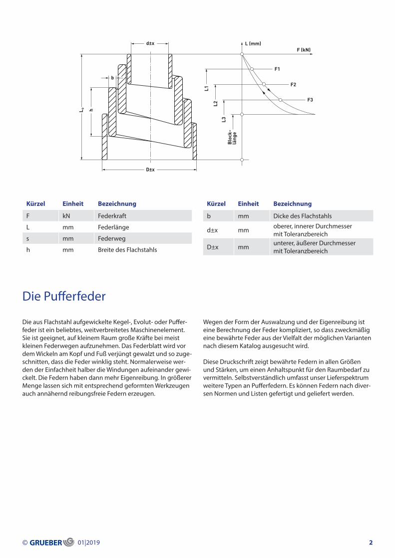
Die Pufferfeder
Kürzel Einheit Bezeichnung
F kN Federkraft
L mm Federlänge
s mm Federweg
h mm Breite des Flachstahls
Kürzel Einheit Bezeichnung
b mm Dicke des Flachstahls
d±x mm oberer, innerer Durchmessermit Toleranzbereich
D±x mm unterer, äußerer Durchmessermit Toleranzbereich
Die aus Flachstahl aufgewickelte Kegel-, Evolut- oder Puffer-feder ist ein beliebtes, weitverbreitetes Maschinenelement. Sie ist geeignet, auf kleinem Raum große Kräfte bei meist kleinen Federwegen aufzunehmen. Das Federblatt wird vor dem Wickeln am Kopf und Fuß verjüngt gewalzt und so zuge-schnitten, dass die Feder winklig steht. Normalerweise wer-den der Einfachheit halber die Windungen aufeinander gewi-ckelt. Die Federn haben dann mehr Eigenreibung. In größerer Menge lassen sich mit entsprechend geformten Werkzeugen auch annähernd reibungsfreie Federn erzeugen.
Wegen der Form der Auswalzung und der Eigenreibung ist eine Berechnung der Feder kompliziert, so dass zweckmäßig eine bewährte Feder aus der Vielfalt der möglichen Varianten nach diesem Katalog ausgesucht wird.
Diese Druckschrift zeigt bewährte Federn in allen Größen und Stärken, um einen Anhaltspunkt für den Raumbedarf zu vermitteln. Selbstverständlich umfasst unser Lieferspektrum weitere Typen an Pufferfedern. Es können Federn nach diver-sen Normen und Listen gefertigt und geliefert werden.
© 01|2019 2
L (mm)F (kN)
F1
L1
L2
L3B
lock
-lä
nge
F2
F3
D±x
d±x
h
bL 0

Werkstoffe
Die aufgeführten Werkstoffe sind zur Herstellung von Puffer-federn geeignet. Wir behalten uns die Auswahl der Stahlsorte sowie geringfügige Abweichungen der in den Tabellen an-gegebenen Querschnitte vor.
Die Vergütungsfestigkeit richtet sich nach der Konstruktion der Feder; normal ist ein Bereich zwischen 1350 N/mm2 und 1700 N/mm2. Die Federn werden nach der Vergütung bis zum Plastizieren vorgesetzt.Dadurch unterliegt jede Feder einem technologischen Festigkeitstest. Nachweise der Festigkeit an der Feder selbst bedürfen besonderer Vereinbarung.
Sorte C %min. / max.
Si %min. / max.
Mn %min. / max.
Cr %min. / max.
V %min. / max.
P + S %max.
51 Si 7 0,47 / 0,55 1,5 / 2,0 0,5 / 0,8 – – 0,045
56 Si 7 0,52 / 0,60 1,6 / 2,0 0,6 / 0,9 – – 0,025
61 SiCr 7 0,57 / 0,65 1,6 / 2,0 0,7 / 1,0 0,2 / 0,4 – 0,030
51 Cr V 4 0,47 / 0,55 0,15 / 0,4 0,7 / 1,1 0,9 / 1,1 0,1 / 0,2 0,030
Sorte Norm Abmessung b (mm) Bemerkung Vergleich mit ISO 683
51 Si 7 Werksnorm (vorher ISO 683/XIV-1973) bis 20 Standardsorte No 4
56 Si 7 EN 10089 3 bis 10 – –
61 SiCr 7 EN 10089 3 bis 12 Standardsorte No 7
51 Cr V 4 EN 10089 3 bis 10 nur in Sonderfällen No 13
Informationen und Hinweise
Vergütungsstähle für Pufferfedern
© 01|2019 3

d ± x mmOberer, innerer Durchmesser
Toleranzbereichmm
von bis von bis
– 25 -1 +2
26 50 -1 +3
51 70 -2 +4
71 90 -3 +5
91 110 -5 +6
111 – -5 +10
d ± x mmUnterer, äußerer Durchmesser
Toleranzbereichmm
von bis von bis
– 50 -2 +2
51 100 -4 +3
101 150 -6 +4
151 200 -8 +6
201 – -10 +8
L0 mmungespannte Länge
Toleranzbereichmm
von bis von bis
– 100 -5 +5
101 200 -5 +7
201 250 -5 +10
251 300 -10 +10
301 350 -10 +15
Die normale Fertigungstoleranz beträgt +30 % / -20 %, bei höheren Anforderungen bedarf es einer Vereinbarung. Mit speziellen Werkzeugen lassen sich in größerer Serie (> 100 Stück) auch Abweichungen < 20 % verwirklichen.
Maßabweichungen / Toleranzen
Innerhalb der hier sowie in der Übersicht angegebenen Toleranzbereiche bleiben die technischen Eigenschaften der Federn unverändert.
Abweichung der Federkräfte
© 01|2019 4

Kennlinie und Wickelrichtung
Je nach dem Grad der Auswalzung ergibt sich eine mehr oder weniger progressive Kennlinie. Die Tabellen nennen zwei Federkräfte und die zugehörigen Längen, eine normale Betriebslast bei ca. 0,5 bis 0,7 des möglichen Federweges und eine empfohlene Endkraft, jenseits derer die Feder stark progressiv wird. Mit unseren Fertigungseinrichtungen können rechts und links gewickelte Pufferfedern hergestellt werden. Die Wickelrichtung hat jedoch keinen Einfluss auf die Funktion der Feder.
Oberfläche / Korrosionsschutz
Wegen der inneren Reibung sollen die Federn gut geölt oder gefettet betrieben werden. Standardmäßig werden die Fe-dern mit geölter Oberfläche geliefert. Nach Vereinbarung ist ein Rostschutz mit schwarzer Farbe, Luxoral Aqua lieferbar.
Kennzeichnung
Die Federn werden auf Wunsch mit Firmenzeichen und Lie-ferjahr am Fuß warm gestempelt. Andere Kennzeichnungen, z. B. zur Unterscheidung mehrerer Sorten Federn oder auch Farbkennzeichnungen können vereinbart werden.
Ausführungshinweise
Betriebsweise und Haltbarkeit
Statischer Einbau oder seltene Betätigung
Hierfür ist die Pufferfeder gut geeignet. Die mittlere Betriebs-last sollte zwischen Normallast und Maximallast liegen und nur gelegentlich Maximallast erreichen(< 104 Lastwechsel). Beispiel: Vorspannfedern; Isolierfedern; Sicherheits-An-schlag-Federn.
Häufige Lastwechsel
Für Schwingungsbeanspruchung mit einer Amplitude w > 0,1 des gesamten Federweges ist die Pufferfeder nicht geeignet. Für häufige Betätigung und eine erwartete Lebens-dauer im Bereich 104 bis 106 Lastwechsel muss eine Feder sorgfältig ausgewählt werden. Einen Anhaltspunkt hierfür gibt die Volumennutzung einer Feder: je nach Ausnutzung des Materials im Bauraum können mehr und weniger stark genutzte Federn unterschieden werden. Hierzu nehmen Sie bitte unsere Beratung in Anspruch. Je weniger der volle Hub genutzt wird, desto länger wird die Lebensdauer sein. Bei Fahrzeugabfederungen muss daher überdimensioniert werden. Die hier gegebenen Hinweise sollen der Vermei-dung grober Fehldimensionierung dienen und stellen keine generelle Eignungszusage dar! Die sonst bei Federn üblichen Maßnahmen zur Verbesserung der Lebensdauer können bei Pufferfedern nicht angewendet werden. Daher ist die Ge-währleistung einer bestimmen Lebensdauer nicht möglich. Beispiele: Abfederung selten betätigter langsam laufender Schwerlastfahrzeuge, Anschläge, Schwermaschinen, Stoß-dämpfung, Krananlagen.
Setzen, Kriechen
Die Federn sind mehrmals auf Block gepresst und haben daher bei Normallast keinen nennenswerten Längenverlust. Bei Maximallast muss über lange Zeit mit einem geringen Längenverlust gerechnet werden.
Arbeitstemperatur
Der Normalbereich ist +80 °C bis -30 °C. Über 80 °C kann es bei Kräften im Bereich der Maximallast zu Setzverlusten kom-men. Bei höherer Temperatur ist eine stärkere Feder zu wäh-len und diese bei mäßiger Last einzusetzen. Unter -30 °C setzt Versprödung der Werkstoffe ein, obwohl die verwendetenSi-haltigen Werkstoffe gut geeignet sind.Es soll auch in diesem Fall eine überdimensionierte Feder ge-wählt werden, deren Festigkeit dann gering gehalten werden kann. Nehmen Sie dazu unsere Beratung in Anspruch.
Betätigungen quer zur Federachse(Querfederung)
Hierfür sind normale Pufferfedern nicht geeignet. In Son-derfällen können Federn mit Windungsabstand hergestellt werden.
Qualitätssicherung
Unsere Pufferfedern werden innerhalb unseres dokumen-tierten und nach DIN EN 9001: 2000 zertifizierten QM-System gefertigt.
© 01|2019 5
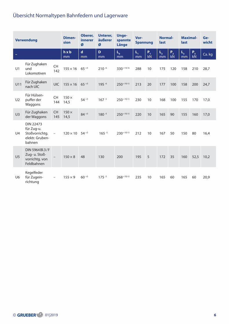
Übersicht Normaltypen Bahnfedern und Lagerware
Verwendung Dimen-sion
Oberer,innererØ
Unterer,äußererØ
Unge-spannteLänge
Vor-Spannung
Normal-last
Maximal-last
Ge-wicht
– h x b mm
d mm
D mm
L0 mm
L1mm
P1kN
L2mm
P2kN
L3mm
P3kN Ca. kg
U1Für Zughaken undLokomotiven
CH142 155 × 16 65 +3 210 -6 330 +
13/-6 288 10 175 120 158 210 28,7
U11 Für Zughakennach UIC UIC 155 × 16 65 +3 195 -6 250 +10/-5 213 20 177 100 158 200 24,7
U2 Für Hülsen-puffer der Waggons
CH144
150 × 14,5 54 +3 167 -5 250 +10/-5 230 10 168 100 155 170 17,0
U3 Für Zughakender Waggons
CH145
150 × 14,5 84 +3 180 -5 250 +10/-5 220 10 165 90 155 160 17,0
U4
DIN 22473 für Zug-u.Stoßvorrichtg.elektr. Gruben-bahnen
– 120 × 10 54 +3 165 -5 230 +10/-5 212 10 167 50 150 80 16,4
U5
DIN 5964 Bl.3 / F Zug- u. Stoß-vorrichtg. von Feldbahnen
– 150 × 8 48 130 200 195 5 172 35 160 52,5 10,2
U6Kegelfeder für Zugein-richtung
– 155 × 9 60 +3 175 -5 268 +10/-5 235 10 165 60 165 60 20,9
© 01|2019 6

Ungespannte Länge L0 (mm) 100 120 140 160
Normallast 3,5 kN – Maximallast 6 kNFeder Nr. B5 B6 B7 B8Dimension h x b (mm) 50 x 4 50 x 4 60 x 4 90 x 4
Länge bei Normallast (mm) 75 80 95 130
Länge bei Maximallast (mm) 65 60 75 115
Gewicht (ca. kg) 1,1 1,2 1,4 2,2
Normallast 6 kN – Maximallast 9 kNFeder Nr. B9 B10 B11 B12Dimension h x b (mm) 70 x 5 70 x 4 70 x 4 90 x 4
Länge bei Normallast (mm) 86 92 100 122
Länge bei Maximallast (mm) 80 82 90 110
Gewicht (ca. kg) 1,5 1,5 1,5 1,9
Normallast 9 kN – Maximallast 15 kNFeder Nr. B13 B14 B15 B16aDimension h x b (mm) 60 x 6 70 x 5 100 x 5 90 x 4
Länge bei Normallast (mm) 80 96 122 110
Länge bei Maximallast (mm) 70 85 116 97
Gewicht (ca. kg) 1,3 1,5 2,1 1,9
Normallast 15 kN – Maximallast 22,5 kNFeder Nr. B17 B18 B19 B20Dimension h x b (mm) 60 x 6 80 x 6 110 x 6 100 x 5
Länge bei Normallast (mm) 70 105 128 130
Länge bei Maximallast (mm) 63 98 123 118
Gewicht (ca. kg) 1,3 1,9 2,3 2,1
Oberer, innerer Durchmesser d:
Unterer, äußerer Durchmesser D:Innerhalb der angegebenen Maßtoleranzen bleiben die technischen Eigenschaften der Federn unverändert.
± 10 mm
± 5 mm
30
75
© 01|2019 7

Ungespannte Länge L0 (mm) 100 120 140 150 160 180
Normallast 3,5 kN – Maximallast 6 kNFeder Nr. C7 C8 C9 C10 C11 C12Dimension h x b (mm) 50 x 4 60 x 4 70 x 4
Länge bei Normallast (mm) 70 95 120
Länge bei Maximallast (mm) 56 80 100
Gewicht (ca. kg) 1,3 1,6 2,0
Normallast 6 kN – Maximallast 9 kNFeder Nr. C13 C14 C15 C16 C17 C18Dimension h x b (mm) 60 x 5 70 x 4 80 x 5 60 x 4 90 x 4Länge bei Normallast (mm) 78 84 110 100 122
Länge bei Maximallast (mm) 68 74 100 80 110
Gewicht (ca. kg) 1,6 1,9 2,1 1,6 2,4
Normallast 9 kN – Maximallast 15 kNFeder Nr. C19 C20 C21a C22 C23 C24Dimension h x b (mm) 50 x 7 70 x 6 80 x 5 90 x 5 100 x 5
Länge bei Normallast (mm) 82 98 100 118 122
Länge bei Maximallast (mm) 75 85 90 108 105
Gewicht (ca. kg) 1,3 1,9 2,1 2,4 3,0
Normallast 15 kN – Maximallast 22,5 kNFeder Nr. C25 C26 C27 C28 C29 C30aDimension h x b (mm) 70 x 7 80 x 6 100 x 6 100 x 5 80 x 6 110 x 6
Länge bei Normallast (mm) 82 92 124 117 120 145
Länge bei Maximallast (mm) 75 85 118 104 102 135
Gewicht (ca. kg) 1,9 2,1 2,7 2,7 2,4 3,7
Normallast 22,5 kN – Maximallast 35 kNFeder Nr. C31 C32 C33 C34 C35 C36Dimension h x b (mm) 70 x 8 70 x 8 100 x 9 110 x 6 130 x 7 130 x 7
Länge bei Normallast (mm) 87 105 125 125 145 162
Länge bei Maximallast (mm) 80 98 120 115 140 155
Gewicht (ca. kg) 2,1 2,4 3,0 2,9 3,5 3,5
Oberer, innerer Durchmesser d:
Unterer, äußerer Durchmesser D:Innerhalb der angegebenen Maßtoleranzen bleiben die technischen Eigenschaften der Federn unverändert.
± 10 mm
± 5 mm
35
85
© 01|2019 8
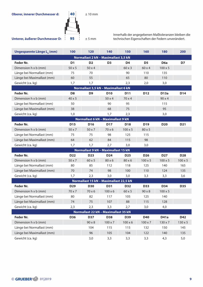
Ungespannte Länge L0 (mm) 100 120 140 150 160 180 200
Normallast 2 kN – Maximallast 3,5 kNFeder Nr. D1 D2 D3 D4 D5 D6a D7Dimension h x b (mm) 50 x 5 50 x 4 60 x 3 60 x 4 100 x 5Länge bei Normallast (mm) 75 70 90 110 135Länge bei Maximallast (mm) 60 55 65 80 110
Gewicht (ca. kg) 1,7 1,7 2,3 2,0 3,0
Normallast 3,5 kN – Maximallast 6 kNFeder Nr. D8 D9 D10 D11 D12 D13a D14Dimension h x b (mm) 40 x 5 50 x 4 70 x 4 90 x 4
Länge bei Normallast (mm) 50 90 95 115
Länge bei Maximallast (mm) 38 68 75 95
Gewicht (ca. kg) 1,0 1,7 2,3 3,0
Normallast 6 kN – Maximallast 9 kNFeder Nr. D15 D16 D17 D18 D19 D20 D21 Dimension h x b (mm) 50 x 7 50 x 7 70 x 6 100 x 5 80 x 5
Länge bei Normallast (mm) 75 75 98 125 115
Länge bei Maximallast (mm) 64 62 84 115 98
Gewicht (ca. kg) 1,7 1,7 2,7 3,0 3,0
Normallast 9 kN – Maximallast 15 kNFeder Nr. D22 D23 D24 D25 D26 D27 D28Dimension h x b (mm) 50 x 7 60 x 5 80 x 6 80 x 6 100 x 5 100 x 5 100 x 5Länge bei Normallast (mm) 80 85 112 118 125 140 165
Länge bei Maximallast (mm) 70 74 98 100 110 124 135
Gewicht (ca. kg) 1,7 2,3 3,0 3,0 3,3 3,3 3,6
Normallast 15 kN – Maximallast 22,5 kNFeder Nr. D29 D30 D31 D32 D33 D34 D35Dimension h x b (mm) 70 x 7 70 x 6 100 x 6 60 x 5 90 x 8 100 x 5
Länge bei Normallast (mm) 80 82 117 105 125 140
Länge bei Maximallast (mm) 74 75 107 88 115 128
Gewicht (ca. kg) 2,3 2,3 3,3 2,7 3,0 4,0
Normallast 22 kN – Maximallast 35 kNFeder Nr. D36 D37 D38 D39 D40 D41a D42Dimension h x b (mm) 90 x 8 100 x 7 100 x 6 100 x 7 130 x 7 130 x 5
Länge bei Normallast (mm) 104 115 115 132 150 145
Länge bei Maximallast (mm) 96 105 104 122 140 135
Gewicht (ca. kg) 3,0 3,3 3,3 3,3 4,3 5,0
Oberer, innerer Durchmesser d:
Unterer, äußerer Durchmesser D:Innerhalb der angegebenen Maßtoleranzen bleiben die technischen Eigenschaften der Federn unverändert.
± 10 mm
± 5 mm
40
95
© 01|2019 9

Ungespannte Länge L0 (mm) 100 120 140 160 180 200
Normallast 3,5 kN – Maximallast 6 kNFeder Nr. E7 E8 E9 E10 E11 E12Dimension h x b (mm) 40 x 5 50 x 5 60 x 4 70 x 4Länge bei Normallast (mm) 52 80 85 110Länge bei Maximallast (mm) 44 62 65 84
Gewicht (ca. kg) 1,8 2,3 2,7 3,6
Normallast 6 kN – Maximallast 9 kNFeder Nr. E13 E14 E15 E16a E17 E18Dimension h x b (mm) 50 x 7 60 x 5 70 x 5 80 x 5 90 x 4 130 x 5
Länge bei Normallast (mm) 72 80 104 115 120 170
Länge bei Maximallast (mm) 58 65 85 95 103 160
Gewicht (ca. kg) 2,3 2,7 3,2 3,7 4,1 5,5
Normallast 9 kN – Maximallast 15 kNFeder Nr. E19 E20 E21 E22 E23 E24Dimension h x b (mm) 70 x 7 70 x 6 100 x 5 100 x 5 130 x 5
Länge bei Normallast (mm) 90 108 118 135 160
Länge bei Maximallast (mm) 75 90 104 120 145
Gewicht (ca. kg) 2,7 3,2 4,6 4,6 5,5
Normallast 15 kN – Maximallast 22,5 kNFeder Nr. E25 E26 E27 E28 E29 E30Dimension h x b (mm) 70 x 8 100 x 7 110 x 6 100 x 6
Länge bei Normallast (mm) 100 135 145 145
Länge bei Maximallast (mm) 90 122 130 125
Gewicht (ca. kg) 3,2 4,6 5,7 4,6
Normallast 22,5 kN – Maximallast 35 kNFeder Nr. E31 E32 E33 E34 E35 E36Dimension h x b (mm) 70 x 10 80 x 7 100 x 7 120 x 8
Länge bei Normallast (mm) 82 98 122 150
Länge bei Maximallast (mm) 75 83 110 138
Gewicht (ca. kg) 3,2 3,7 4,6 5,5
Normallast 35 kN – Maximallast 50 kNFeder Nr. E37 E38 E39 E40 E41 E42Dimension h x b (mm) 50 x 10 100 x 9 120 x 8
Länge bei Normallast (mm) 65 122 162
Länge bei Maximallast (mm) 55 108 155
Gewicht (ca. kg) 2,3 4,6 6,4
Oberer, innerer Durchmesser d:
Unterer, äußerer Durchmesser D:Innerhalb der angegebenen Maßtoleranzen bleiben die technischen Eigenschaften der Federn unverändert.
± 10 mm
± 5 mm
30
105
© 01|2019 10
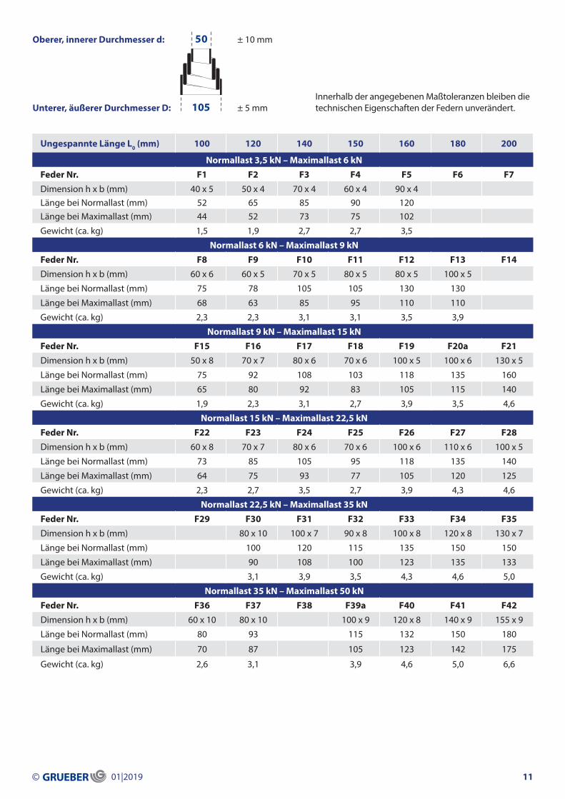
Ungespannte Länge L0 (mm) 100 120 140 150 160 180 200
Normallast 3,5 kN – Maximallast 6 kNFeder Nr. F1 F2 F3 F4 F5 F6 F7Dimension h x b (mm) 40 x 5 50 x 4 70 x 4 60 x 4 90 x 4Länge bei Normallast (mm) 52 65 85 90 120Länge bei Maximallast (mm) 44 52 73 75 102
Gewicht (ca. kg) 1,5 1,9 2,7 2,7 3,5
Normallast 6 kN – Maximallast 9 kNFeder Nr. F8 F9 F10 F11 F12 F13 F14Dimension h x b (mm) 60 x 6 60 x 5 70 x 5 80 x 5 80 x 5 100 x 5
Länge bei Normallast (mm) 75 78 105 105 130 130
Länge bei Maximallast (mm) 68 63 85 95 110 110
Gewicht (ca. kg) 2,3 2,3 3,1 3,1 3,5 3,9
Normallast 9 kN – Maximallast 15 kNFeder Nr. F15 F16 F17 F18 F19 F20a F21Dimension h x b (mm) 50 x 8 70 x 7 80 x 6 70 x 6 100 x 5 100 x 6 130 x 5
Länge bei Normallast (mm) 75 92 108 103 118 135 160
Länge bei Maximallast (mm) 65 80 92 83 105 115 140
Gewicht (ca. kg) 1,9 2,3 3,1 2,7 3,9 3,5 4,6
Normallast 15 kN – Maximallast 22,5 kNFeder Nr. F22 F23 F24 F25 F26 F27 F28Dimension h x b (mm) 60 x 8 70 x 7 80 x 6 70 x 6 100 x 6 110 x 6 100 x 5
Länge bei Normallast (mm) 73 85 105 95 118 135 140
Länge bei Maximallast (mm) 64 75 93 77 105 120 125
Gewicht (ca. kg) 2,3 2,7 3,5 2,7 3,9 4,3 4,6
Normallast 22,5 kN – Maximallast 35 kNFeder Nr. F29 F30 F31 F32 F33 F34 F35Dimension h x b (mm) 80 x 10 100 x 7 90 x 8 100 x 8 120 x 8 130 x 7
Länge bei Normallast (mm) 100 120 115 135 150 150
Länge bei Maximallast (mm) 90 108 100 123 135 133
Gewicht (ca. kg) 3,1 3,9 3,5 4,3 4,6 5,0
Normallast 35 kN – Maximallast 50 kNFeder Nr. F36 F37 F38 F39a F40 F41 F42Dimension h x b (mm) 60 x 10 80 x 10 100 x 9 120 x 8 140 x 9 155 x 9
Länge bei Normallast (mm) 80 93 115 132 150 180
Länge bei Maximallast (mm) 70 87 105 123 142 175
Gewicht (ca. kg) 2,6 3,1 3,9 4,6 5,0 6,6
Oberer, innerer Durchmesser d:
Unterer, äußerer Durchmesser D:Innerhalb der angegebenen Maßtoleranzen bleiben die technischen Eigenschaften der Federn unverändert.
± 10 mm
± 5 mm
50
105
© 01|2019 11
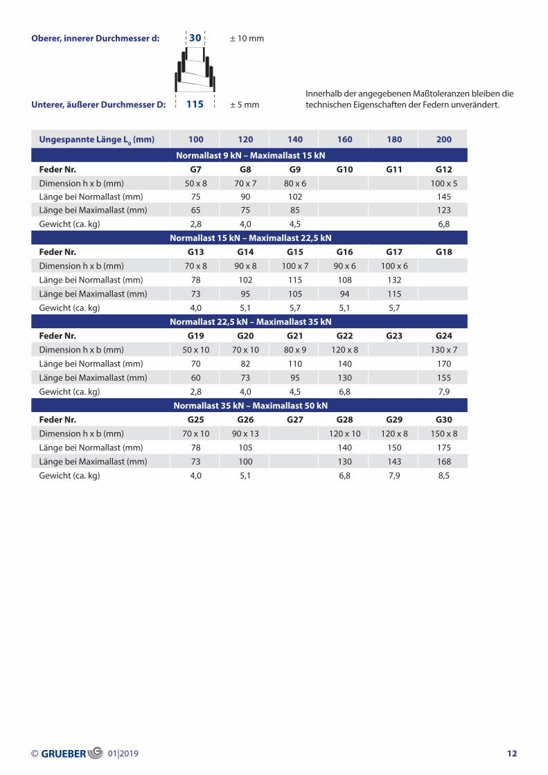
Ungespannte Länge L0 (mm) 100 120 140 160 180 200
Normallast 9 kN – Maximallast 15 kNFeder Nr. G7 G8 G9 G10 G11 G12Dimension h x b (mm) 50 x 8 70 x 7 80 x 6 100 x 5Länge bei Normallast (mm) 75 90 102 145Länge bei Maximallast (mm) 65 75 85 123
Gewicht (ca. kg) 2,8 4,0 4,5 6,8
Normallast 15 kN – Maximallast 22,5 kNFeder Nr. G13 G14 G15 G16 G17 G18Dimension h x b (mm) 70 x 8 90 x 8 100 x 7 90 x 6 100 x 6
Länge bei Normallast (mm) 78 102 115 108 132
Länge bei Maximallast (mm) 73 95 105 94 115
Gewicht (ca. kg) 4,0 5,1 5,7 5,1 5,7
Normallast 22,5 kN – Maximallast 35 kNFeder Nr. G19 G20 G21 G22 G23 G24Dimension h x b (mm) 50 x 10 70 x 10 80 x 9 120 x 8 130 x 7
Länge bei Normallast (mm) 70 82 110 140 170
Länge bei Maximallast (mm) 60 73 95 130 155
Gewicht (ca. kg) 2,8 4,0 4,5 6,8 7,9
Normallast 35 kN – Maximallast 50 kNFeder Nr. G25 G26 G27 G28 G29 G30Dimension h x b (mm) 70 x 10 90 x 13 120 x 10 120 x 8 150 x 8
Länge bei Normallast (mm) 78 105 140 150 175
Länge bei Maximallast (mm) 73 100 130 143 168
Gewicht (ca. kg) 4,0 5,1 6,8 7,9 8,5
Oberer, innerer Durchmesser d:
Unterer, äußerer Durchmesser D:Innerhalb der angegebenen Maßtoleranzen bleiben die technischen Eigenschaften der Federn unverändert.
± 10 mm
± 5 mm
30
115
© 01|2019 12
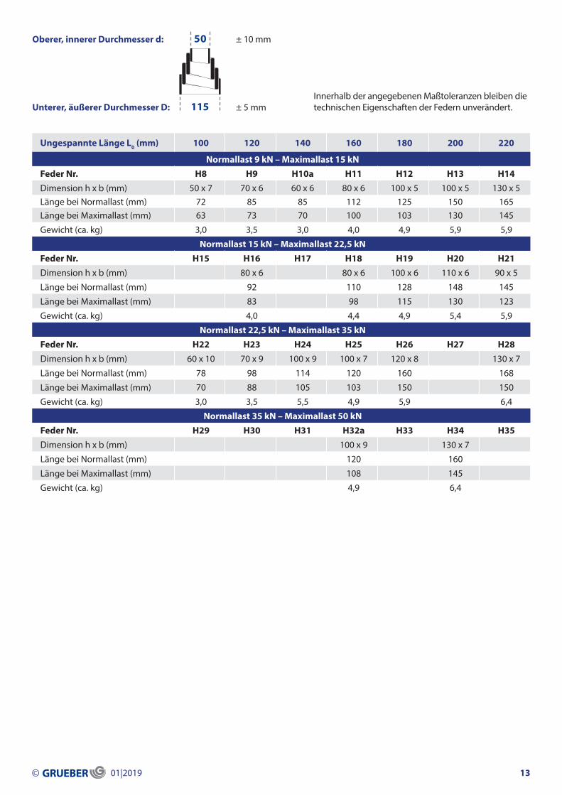
Ungespannte Länge L0 (mm) 100 120 140 160 180 200 220
Normallast 9 kN – Maximallast 15 kNFeder Nr. H8 H9 H10a H11 H12 H13 H14Dimension h x b (mm) 50 x 7 70 x 6 60 x 6 80 x 6 100 x 5 100 x 5 130 x 5Länge bei Normallast (mm) 72 85 85 112 125 150 165Länge bei Maximallast (mm) 63 73 70 100 103 130 145
Gewicht (ca. kg) 3,0 3,5 3,0 4,0 4,9 5,9 5,9
Normallast 15 kN – Maximallast 22,5 kNFeder Nr. H15 H16 H17 H18 H19 H20 H21Dimension h x b (mm) 80 x 6 80 x 6 100 x 6 110 x 6 90 x 5
Länge bei Normallast (mm) 92 110 128 148 145
Länge bei Maximallast (mm) 83 98 115 130 123
Gewicht (ca. kg) 4,0 4,4 4,9 5,4 5,9
Normallast 22,5 kN – Maximallast 35 kNFeder Nr. H22 H23 H24 H25 H26 H27 H28Dimension h x b (mm) 60 x 10 70 x 9 100 x 9 100 x 7 120 x 8 130 x 7
Länge bei Normallast (mm) 78 98 114 120 160 168
Länge bei Maximallast (mm) 70 88 105 103 150 150
Gewicht (ca. kg) 3,0 3,5 5,5 4,9 5,9 6,4
Normallast 35 kN – Maximallast 50 kNFeder Nr. H29 H30 H31 H32a H33 H34 H35Dimension h x b (mm) 100 x 9 130 x 7
Länge bei Normallast (mm) 120 160
Länge bei Maximallast (mm) 108 145
Gewicht (ca. kg) 4,9 6,4
Oberer, innerer Durchmesser d:
Unterer, äußerer Durchmesser D:Innerhalb der angegebenen Maßtoleranzen bleiben die technischen Eigenschaften der Federn unverändert.
± 10 mm
± 5 mm
50
115
© 01|2019 13

Ungespannte Länge L0 (mm) 120 140 160 180 200 225 250
Normallast 6 kN – Maximallast 9 kNFeder Nr. J1 J2 J3 J4 J5 J6 J7Dimension h x b (mm) 50 x 7 60 x 6 80 x 6 80 x 5 90 x 5Länge bei Normallast (mm) 85 100 115 110 110Länge bei Maximallast (mm) 70 85 102 88 92
Gewicht (ca. kg) 3,2 3,8 5,1 5,1 5,8
Normallast 9 kN – Maximallast 15 kNFeder Nr. J8 J9 J10 J11 J12 J13a J14Dimension h x b (mm) 70 x 8 70 x 7 70 x 7 110 x 6 110 x 6 100 x 5
Länge bei Normallast (mm) 90 98 112 135 145 150
Länge bei Maximallast (mm) 75 80 85 115 118 115
Gewicht (ca. kg) 4,5 4,5 4,4 7,0 6,4 6,4
Normallast 15 kN – Maximallast 22,5 kNFeder Nr. J15 J16 J17 J18 J19 J20 J21Dimension h x b (mm) 100 x 7 130 x 7 130 x 7
Länge bei Normallast (mm) 148 152 170
Länge bei Maximallast (mm) 130 135 148
Gewicht (ca. kg) 7,0 8,3 9,0
Normallast 22,5 kN – Maximallast 35 kNFeder Nr. J22 J23 J24 J25 J26 J27 J28Dimension h x b (mm) 70 x 8 100 x 9 100 x 8 100 x 7 130 x 7
Länge bei Normallast (mm) 90 118 132 140 155
Länge bei Maximallast (mm) 75 110 120 128 145
Gewicht (ca. kg) 4,5 6,4 7,0 7,0 9,0
Normallast 35 kN – Maximallast 50 kNFeder Nr. J29 J30 J31 J32 J33 J34 J35Dimension h x b (mm) 80 x 10 120 x 8 100 x 10 150 x 8
Länge bei Normallast (mm) 90 132 150 190
Länge bei Maximallast (mm) 83 123 132 175
Gewicht (ca. kg) 5,1 7,7 6,4 9,6
Normallast 50 kN – Maximallast 80 kNFeder Nr. J36 J37 J38 J39 J40 J41 J42aDimension h x b (mm) 100 x 12 120 x 10 160 x 10 170 x 10
Länge bei Normallast (mm) 115 160 195 215
Länge bei Maximallast (mm) 108 150 185 205
Gewicht (ca. kg) 6,4 9,3 10,3 11,6
Normallast 80 kN – Maximallast 120 kNFeder Nr. J43 J44 J45 J46 J47 J48 J49aDimension h x b (mm) 120 x 13 160 x 12 170 x 10
Länge bei Normallast (mm) 142 200 205
Länge bei Maximallast (mm) 135 190 195
Gewicht (ca. kg) 7,7 10,9 11,6
Oberer, innerer Durchmesser d:
Unterer, äußerer Durchmesser D:Innerhalb der angegebenen Maßtoleranzen bleiben die technischen Eigenschaften der Federn unverändert.
± 5 / – 15 mm
± 5 mm
40
125
© 01|2019 14

Ungespannte Länge L0 (mm) 160 180 200 225 250
Normallast 6 kN – Maximallast 9 kNFeder Nr. K1 K2 K3 K4 K5aDimension h x b (mm) 60 x 5 90 x 5 100 x 5 100 x 5 130 x 5Länge bei Normallast (mm) 85 130 155 130 190Länge bei Maximallast (mm) 63 105 130 105 170
Gewicht (ca. kg) 3,6 5,4 6,0 6,6 7,2
Normallast 9 kN – Maximallast 15 kNFeder Nr. K6 K7 K8 K9 K10Dimension h x b (mm) 80 x 7 100 x 6 100 x 6 110 x 6 130 x 5
Länge bei Normallast (mm) 115 144 138 175 170
Länge bei Maximallast (mm) 98 125 115 150 150
Gewicht (ca. kg) 4,8 6,0 6,6 6,6 7,2
Normallast 15 kN – Maximallast 22,5 kNFeder Nr. K11 K12 K13 K14 K15Dimension h x b (mm) 100 x 7 100 x 6 110 x 6 130 x 7 130 x 7
Länge bei Normallast (mm) 120 125 145 170 200
Länge bei Maximallast (mm) 108 108 120 148 180
Gewicht (ca. kg) 6,0 6,0 6,6 7,8 8,7
Normallast 22,5 kN – Maximallast 35 kNFeder Nr. K16 K17 K18 K19 K20Dimension h x b (mm) 100 x 9 120 x 8 100 x 7 130 x 7
Länge bei Normallast (mm) 125 145 148 182
Länge bei Maximallast (mm) 110 135 130 165
Gewicht (ca. kg) 6,0 7,2 6,6 8,5
Normallast 35 kN – Maximallast 50 kNFeder Nr. K21 K22 K23 K24 K25Dimension h x b (mm) 120 x 10 140 x 9 140 x 9 170 x 10 155 x 9
Länge bei Normallast (mm) 135 145 160 200 195
Länge bei Maximallast (mm) 130 138 148 190 178
Gewicht (ca. kg) 7,2 7,8 7,2 10,3 10,1
Normallast 50 kN – Maximallast 80 kNFeder Nr. K26 K27a K28 K29 K30Dimension h x b (mm) 120 x 13 120 x 10 120 x 10
Länge bei Normallast (mm) 140 148 170
Länge bei Maximallast (mm) 132 135 160
Gewicht (ca. kg) 7,2 7,2 8,8
© 01|2019 15
Oberer, innerer Durchmesser d:
Unterer, äußerer Durchmesser D:Innerhalb der angegebenen Maßtoleranzen bleiben die technischen Eigenschaften der Federn unverändert.
+ 15 / – 5 mm
± 5 mm
50
125

Ungespannte Länge L0 (mm) 160 180 200 225 250
Normallast 9 kN – Maximallast 15 kNFeder Nr. L1 L2 L3 L4 L5Dimension h x b (mm) 60 x 6 100 x 6 100 x 5 100 x 5Länge bei Normallast (mm) 95 125 140 170Länge bei Maximallast (mm) 65 105 110 135
Gewicht (ca. kg) 4,6 7,7 7,7 9,2
Normallast 15 kN – Maximallast 22,5 kNFeder Nr. L6 L7 L8 L9 L10Dimension h x b (mm) 100 x 7 70 x 8 70 x 8 130 x 7
Länge bei Normallast (mm) 115 130 140 190
Länge bei Maximallast (mm) 104 105 125 160
Gewicht (ca. kg) 7,7 6,7 8,5 11,7
Normallast 22,5 kN – Maximallast 35 kNFeder Nr. L11 L12 L13 L14 L15Dimension h x b (mm) 100 x 9 100 x 8 120 x 8 140 x 9
Länge bei Normallast (mm) 128 132 165 172
Länge bei Maximallast (mm) 115 118 150 150
Gewicht (ca. kg) 7,7 8,5 9,2 10,8
Normallast 35 kN – Maximallast 50 kNFeder Nr. L16 L17 L18 L19 L20Dimension h x b (mm) 80 x 10 100 x 10 140 x 9 150 x 8
Länge bei Normallast (mm) 110 135 158 175
Länge bei Maximallast (mm) 98 120 145 160
Gewicht (ca. kg) 6,8 7,7 10,0 11,5
Normallast 50 kN – Maximallast 80 kNFeder Nr. L21 L22 L23 L24 L25Dimension h x b (mm) 100 x 12 120 x 10 100 x 13 150 x 11 170 x 10
Länge bei Normallast (mm) 135 138 165 185 215
Länge bei Maximallast (mm) 125 128 150 165 200
Gewicht (ca. kg) 8,4 9,2 8,5 11,1 13,8
Normallast 80 kN – Maximallast 120 kNFeder Nr. L26 L27 L28a L29 L30Dimension h x b (mm) 120 x 13 150 x 13 175 x 15
Länge bei Normallast (mm) 145 175 210
Länge bei Maximallast (mm) 128 165 202
Gewicht (ca. kg) 9,2 11,5 13,8
© 01|2019 16
Oberer, innerer Durchmesser d:
Unterer, äußerer Durchmesser D:Innerhalb der angegebenen Maßtoleranzen bleiben die technischen Eigenschaften der Federn unverändert.
+ 5 / – 15 mm
± 5 mm
40
135

Ungespannte Länge L0 (mm) 160 180 200 225 250 275
Normallast 9 kN – Maximallast 15 kNFeder Nr. M1 M2 M3 M4 M5 M6Dimension h x b (mm) 80 x 7 100 x 6 80 x 6 110 x 6 100 x 5 110 x 6Länge bei Normallast (mm) 120 140 125 160 150 175Länge bei Maximallast (mm) 100 120 98 135 115 135
Gewicht (ca. kg) 5,8 7,3 5,8 8,0 7,3 9,7
Normallast 15 kN – Maximallast 22,5 kNFeder Nr. M7 M8 M9a M10 M11 M12Dimension h x b (mm) 70 x 8 100 x 7 110 x 6 130 x 7 130 x 7
Länge bei Normallast (mm) 115 140 135 155 210
Länge bei Maximallast (mm) 98 128 115 135 190
Gewicht (ca. kg) 5,8 8,0 8,0 9,5 10,2
Normallast 22,5 kN – Maximallast 35 kNFeder Nr. M13 M14 M15 M16 M17 M18Dimension h x b (mm) 100 x 8 120 x 8 120 x 8 130 x 7 150 x 8 130 x 7
Länge bei Normallast (mm) 120 145 150 180 195 185
Länge bei Maximallast (mm) 113 130 130 160 175 135
Gewicht (ca. kg) 8,0 8,8 9,5 10,2 11,0 9,5
Normallast 35 kN – Maximallast 50 kNFeder Nr. M19 M20 M21 M22 M23 M24Dimension h x b (mm) 120 x 10 100 x 9 120 x 8 140 x 9 170 x 10
Länge bei Normallast (mm) 135 130 150 170 220
Länge bei Maximallast (mm) 128 110 132 148 195
Gewicht (ca. kg) 8,8 7,3 8,8 10,2 12,4
Normallast 50 kN – Maximallast 80 kNFeder Nr. M25a M26a M27 M28 M29 M30Dimension h x b (mm) 90 x 10 120 x 13 140 x 9 155 x 9 160 x 10 190 x 10
Länge bei Normallast (mm) 110 142 152 190 195 250
Länge bei Maximallast (mm) 95 126 143 175 175 235
Gewicht (ca. kg) 6,6 8,8 11,1 10,6 11,7 13,9
Normallast 80 kN – Maximallast 120 kNFeder Nr. M31a M32 M33 M34 M35 M36Dimension h x b (mm) 100 x 12 120 x 13 160 x 14 190 x 10
Länge bei Normallast (mm) 118 150 175 235
Länge bei Maximallast (mm) 105 135 165 215
Gewicht (ca. kg) 7,3 9,5 11,7 13,9
© 01|2019 17
Oberer, innerer Durchmesser d:
Unterer, äußerer Durchmesser D:Innerhalb der angegebenen Maßtoleranzen bleiben die technischen Eigenschaften der Federn unverändert.
+ 15 / – 5 mm
± 5 mm
50
135

Ungespannte Länge L0 (mm) 175 200 220 240 260 280
Normallast 9 kN – Maximallast 15 kNFeder Nr. N1 N2 N3 N4 N5 N6Dimension h x b (mm) 70 x 5 80 x 6 130 x 7 130 x 5Länge bei Normallast (mm) 80 * 130 165 175Länge bei Maximallast (mm) – 98 140 125
Gewicht (ca. kg) 6,0 7,8 11,2 10,3
Normallast 15 kN – Maximallast 22,5 kNFeder Nr. N7 N8 N9 N10 N11 N12Dimension h x b (mm) 100 x 7 130 x 7 130 x 7
Länge bei Normallast (mm) 135 195 190
Länge bei Maximallast (mm) 110 168 150
Gewicht (ca. kg) 8,6 12,1 11,2
Normallast 22,5 kN – Maximallast 35 kNFeder Nr. N13 N14 N15 N16 N17 N18Dimension h x b (mm) 100 x 8 140 x 9 150 x 8 130 x 7 150 x 8
Länge bei Normallast (mm) 158 162 180 190 210
Länge bei Maximallast (mm) 140 140 158 170 180
Gewicht (ca. kg) 9,5 10,3 12,9 12,3 12,9
Normallast 35 kN – Maximallast 50 kNFeder Nr. N19 N20 N21 N22 N23 N24Dimension h x b (mm) 100 x 10 120 x 10 140 x 9 150 x 8 150 x 8
Länge bei Normallast (mm) 132 145 160 205 180
Länge bei Maximallast (mm) 110 128 145 185 155
Gewicht (ca. kg) 8,6 11,3 12,1 14,2 12,9
Normallast 50 kN – Maximallast 80 kNFeder Nr. N25 N26 N27 N28a N29a N30Dimension h x b (mm) 120 x 10 138 x 11 160 x 10 170 x 10
Länge bei Normallast (mm) 166 180 195 215
Länge bei Maximallast (mm) 150 162 180 200
Gewicht (ca. kg) 12,5 11,9 13,8 15,6
Normallast 80 kN – Maximallast 120 kNFeder Nr. N31 N32 N33 N34 N35 N36Dimension h x b (mm) 120 x 13 120 x 13 150 x 13 150 x 13
Länge bei Normallast (mm) 140 160 178 210
Länge bei Maximallast (mm) 126 148 168 200
Gewicht (ca. kg) 10,3 12,1 12,9 14,7
* (max. Belastung)
© 01|2019 18
Oberer, innerer Durchmesser d:
Unterer, äußerer Durchmesser D:Innerhalb der angegebenen Maßtoleranzen bleiben die technischen Eigenschaften der Federn unverändert.
± 10 mm
± 5 mm
50
145

Ungespannte Länge L0 (mm) 175 200 220 240 260 280
Normallast 9 kN – Maximallast 15 kNFeder Nr. O1 O2 O3 O4 O5 O6Dimension h x b (mm) 100 x 7 80 x 6 100 x 5Länge bei Normallast (mm) 135 120 125Länge bei Maximallast (mm) 115 85 –
Gewicht (ca. kg) 11,0 8,0 11,0
Normallast 15 kN – Maximallast 22,5 kNFeder Nr. O7 O8 O9 O10 O11a O12Dimension h x b (mm) 100 x 9 120 x 8 100 x 7 150 x 8 130 x 7
Länge bei Normallast (mm) 138 160 140 205 195
Länge bei Maximallast (mm) 125 145 112 190 150
Gewicht (ca. kg) 10,0 12,0 10,0 15,0 13,0
Normallast 22,5 kN – Maximallast 35 kNFeder Nr. O13 O14 O15 O16 O17 O18Dimension h x b (mm) 80 x 9 100 x 9 120 x 8 140 x 9 150 x 8
Länge bei Normallast (mm) 115 125 155 185 190
Länge bei Maximallast (mm) 90 104 135 165 165
Gewicht (ca. kg) 8,0 10,0 12,0 14,0 15,0
Normallast 35 kN – Maximallast 50 kNFeder Nr. O19 O20 O21 O22 O23 O24Dimension h x b (mm) 100 x 10 138 x 11 140 x 9 150 x 8 170 x 10
Länge bei Normallast (mm) 115 162 170 175 210
Länge bei Maximallast (mm) 105 150 154 160 190
Gewicht (ca. kg) 10,0 13,8 15,4 15,0 17,0
Normallast 50 kN – Maximallast 80 kNFeder Nr. O25 O26 O27 O28 O29 O30Dimension h x b (mm) 100 x 12 120 x 10 140 x 9 170 x 10 170 x 10
Länge bei Normallast (mm) 130 158 185 205 200
Länge bei Maximallast (mm) 112 135 160 190 175
Gewicht (ca. kg) 10,0 13,0 14,5 18,0 17,0
Normallast 80 kN – Maximallast 120 kNFeder Nr. O31 O32 O33 O34 O35 O36Dimension h x b (mm) 120 x 13 120 x 13 138 x 11 160 x 12 180 x 13
Länge bei Normallast (mm) 150 170 170 200 230
Länge bei Maximallast (mm) 140 160 150 182 218
Gewicht (ca. kg) 13,0 14,0 13,8 17,0 18,0
© 01|2019 19
Oberer, innerer Durchmesser d:
Unterer, äußerer Durchmesser D:Innerhalb der angegebenen Maßtoleranzen bleiben die technischen Eigenschaften der Federn unverändert.
± 10 mm
± 5 mm
50
155

Ungespannte Länge L0 (mm) 175 200 220 240 260 280 300
Normallast 9 kN – Maximallast 15 kNFeder Nr. P1 P2 P3 P4 P5 P6 P7Dimension h x b (mm) 100 x 8 80 x 7 80 x 6 100 x 7 100 x 6 130 x 7 130 x 7Länge bei Normallast (mm) 140 115 110 180 160 195 210Länge bei Maximallast (mm) 124 87 92 150 120 170 180
Gewicht (ca. kg) 12,1 8,8 9,9 12,1 12,1 15,4 15,7
Normallast 15 kN – Maximallast 22,5 kNFeder Nr. P8 P9a P10 P11 P12 P13 P14Dimension h x b (mm) 100 x 9 100 x 7 140 x 9 130 x 7 120 x 8 130 x 7
Länge bei Normallast (mm) 125 120 175 170 155 170
Länge bei Maximallast (mm) 108 105 158 145 128 145
Gewicht (ca. kg) 11,0 11,0 15,4 15,4 13,2 15,4
Normallast 22,5 kN – Maximallast 35 kNFeder Nr. P15 P16 P17 P18 P19 P20a P21Dimension h x b (mm) 80 x 10 130 x 7 150 x 8 170 x 10
Länge bei Normallast (mm) 110 160 195 230
Länge bei Maximallast (mm) 90 135 170 205
Gewicht (ca. kg) 8,8 14,3 15,4 18,7
Normallast 35 kN – Maximallast 50 kNFeder Nr. P22 P23 P24 P25 P26 P27 P28Dimension h x b (mm) 100 x 12 120 x 10 120 x 10 120 x 10 160 x 10 170 x 10
Länge bei Normallast (mm) 138 150 170 160 218 205
Länge bei Maximallast (mm) 125 135 155 140 195 185
Gewicht (ca. kg) 11,0 13,2 15,9 14,3 17,6 18,7
Normallast 50 kN – Maximallast 80 kNFeder Nr. P29 P30 P31 P32 P33 P34 P35Dimension h x b (mm) 100 x 12 140 x 13 150 x 13 140 x 9 180 x 13 180 x 13
Länge bei Normallast (mm) 125 165 192 180 205 250
Länge bei Maximallast (mm) 105 150 180 160 188 230
Gewicht (ca. kg) 11,0 15,4 17,6 15,9 19,8 21,6
Normallast 80 kN – Maximallast 120 kNFeder Nr. P36 P37 P38 P39 P40 P41a P42Dimension h x b (mm) 160 x 14 150 x 13 160 x 12 150 x 14,5 180 x 13
Länge bei Normallast (mm) 172 178 183 185 220
Länge bei Maximallast (mm) 164 160 165 175 205
Gewicht (ca. kg) 17,6 16,5 17,6 16,5 19,8
Normallast 120 kN – Maximallast 200 kNFeder Nr. P43 P44 P45 P46 P47a P48 P49Dimension h x b (mm) 155 x 16 175 x 15 175 x 15 190 x 14
Länge bei Normallast (mm) 180 195 200 210
Länge bei Maximallast (mm) 165 185 185 195
Gewicht (ca. kg) 17,0 18,7 19,8 20,9
© 01|2019 20
Oberer, innerer Durchmesser d:
Unterer, äußerer Durchmesser D:Innerhalb der angegebenen Maßtoleranzen bleiben die technischen Eigenschaften der Federn unverändert.
± 10 mm
± 5 mm
60
165

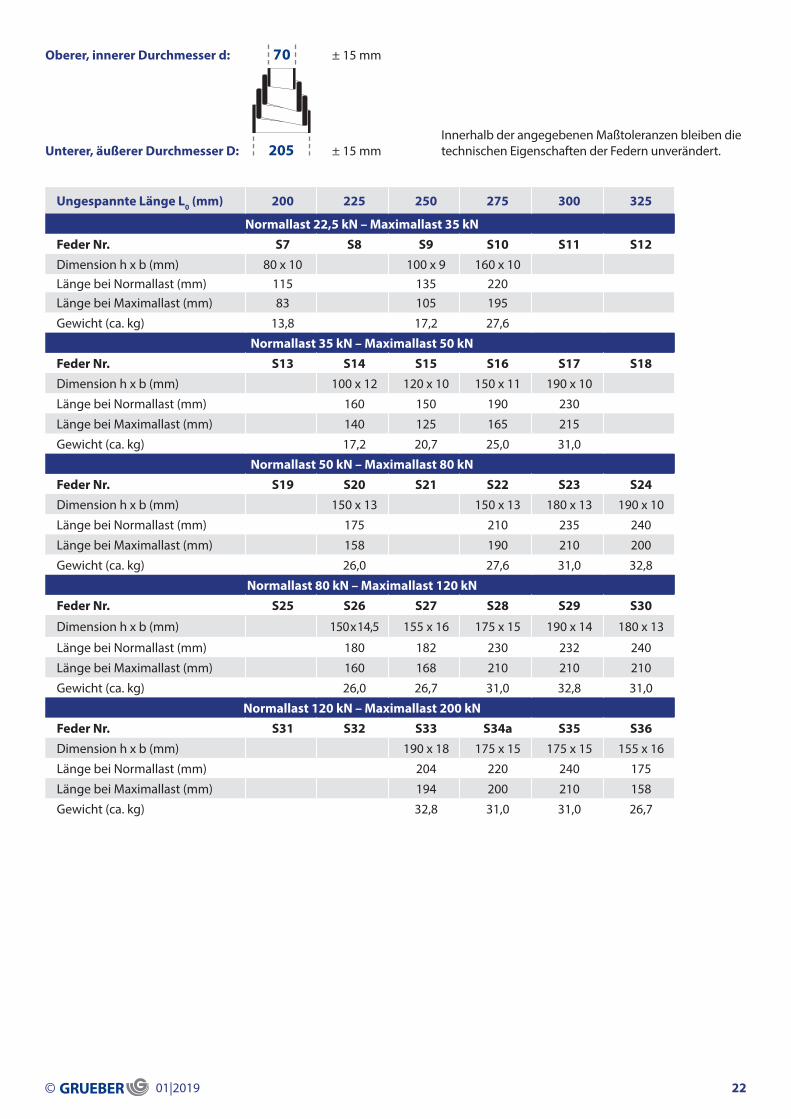
Ungespannte Länge L0 (mm) 175 200 225 250 275 300
Normallast 15 kN – Maximallast 22,5 kNFeder Nr. R1 R2 R3 R4 R5 R6Dimension h x b (mm) 70 x 8 120 x 8 100 x 8 140 x 9Länge bei Normallast (mm) 110 125 * 150 180Länge bei Maximallast (mm) 80 – 115 150
Gewicht (ca. kg) 8,5 14,5 13,3 16,9
Normallast 22,5 kN – Maximallast 35 kNFeder Nr. R7 R8 R9 R10 R11a R12Dimension h x b (mm) 90 x 10 120 x 8 150 x 8 170 x 10
Länge bei Normallast (mm) 130 165 185 215
Länge bei Maximallast (mm) 112 142 158 185
Gewicht (ca. kg) 9,7 15,7 18,1 20,6
Normallast 35 kN – Maximallast 50 kNFeder Nr. R13 R14 R15 R16 R17 R18Dimension h x b (mm) 90 x 13 120 x 10 120 x 10 160 x 10 140 x 9 170 x 10
Länge bei Normallast (mm) 125 140 170 190 180 235
Länge bei Maximallast (mm) 110 128 155 175 168 210
Gewicht (ca. kg) 10,9 14,5 17,5 19,4 15,7 21,8
Normallast 50 kN – Maximallast 80 kNFeder Nr. R19 R20 R21 R22 R23 R24a
Dimension h x b (mm) 120 x 13 150 x 13 138 x 11 160 x 12 190 x 10 170 x 10
Länge bei Normallast (mm) 138 162 175 212 215 210
Länge bei Maximallast (mm) 123 153 150 195 195 185
Gewicht (ca. kg) 14,5 18,1 16,7 20,6 23,0 21,8
Normallast 80 kN – Maximallast 120 kNFeder Nr. R25 R26 R27 R28 R29 R30Dimension h x b (mm) 160 x 14 175 x 15 150 x 14,5 180 x 13 180 x 13
Länge bei Normallast (mm) 170 200 172 215 235
Länge bei Maximallast (mm) 164 190 162 198 215
Gewicht (ca. kg) 19,4 21,8 18,1 21,8 29,3
Normallast 120 kN – Maximallast 200 kNFeder Nr. R31 R32 R33 R34a R35a R36Dimension h x b (mm) 160 x 14 175 x 15 175 x 15 190 x 14
Länge bei Normallast (mm) 180 200 210 230
Länge bei Maximallast (mm) 164 182 190 212
Gewicht (ca. kg) 19,4 20,6 21,8 23,0
* (max. Belastung)
Oberer, innerer Durchmesser d:
Unterer, äußerer Durchmesser D:Innerhalb der angegebenen Maßtoleranzen bleiben die technischen Eigenschaften der Federn unverändert.
© 01|2019 21
± 10 mm
± 15 mm
80
180
Ungespannte Länge L0 (mm) 200 225 250 275 300 325
Normallast 22,5 kN – Maximallast 35 kNFeder Nr. S7 S8 S9 S10 S11 S12Dimension h x b (mm) 80 x 10 100 x 9 160 x 10Länge bei Normallast (mm) 115 135 220Länge bei Maximallast (mm) 83 105 195
Gewicht (ca. kg) 13,8 17,2 27,6
Normallast 35 kN – Maximallast 50 kNFeder Nr. S13 S14 S15 S16 S17 S18Dimension h x b (mm) 100 x 12 120 x 10 150 x 11 190 x 10
Länge bei Normallast (mm) 160 150 190 230
Länge bei Maximallast (mm) 140 125 165 215
Gewicht (ca. kg) 17,2 20,7 25,0 31,0
Normallast 50 kN – Maximallast 80 kNFeder Nr. S19 S20 S21 S22 S23 S24Dimension h x b (mm) 150 x 13 150 x 13 180 x 13 190 x 10
Länge bei Normallast (mm) 175 210 235 240
Länge bei Maximallast (mm) 158 190 210 200
Gewicht (ca. kg) 26,0 27,6 31,0 32,8
Normallast 80 kN – Maximallast 120 kNFeder Nr. S25 S26 S27 S28 S29 S30
Dimension h x b (mm) 150 x 14,5 155 x 16 175 x 15 190 x 14 180 x 13
Länge bei Normallast (mm) 180 182 230 232 240
Länge bei Maximallast (mm) 160 168 210 210 210
Gewicht (ca. kg) 26,0 26,7 31,0 32,8 31,0
Normallast 120 kN – Maximallast 200 kNFeder Nr. S31 S32 S33 S34a S35 S36Dimension h x b (mm) 190 x 18 175 x 15 175 x 15 155 x 16
Länge bei Normallast (mm) 204 220 240 175
Länge bei Maximallast (mm) 194 200 210 158
Gewicht (ca. kg) 32,8 31,0 31,0 26,7
© 01|2019 22
Oberer, innerer Durchmesser d:
Unterer, äußerer Durchmesser D:
± 15 mm
± 15 mmInnerhalb der angegebenen Maßtoleranzen bleiben die technischen Eigenschaften der Federn unverändert.
70
205
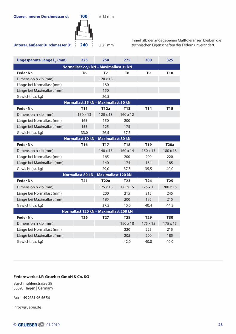
Oberer, innerer Durchmesser d:
Unterer, äußerer Durchmesser D:
± 15 mm
± 25 mmInnerhalb der angegebenen Maßtoleranzen bleiben die technischen Eigenschaften der Federn unverändert.
Ungespannte Länge L0 (mm) 225 250 275 300 325
Normallast 22,5 kN – Maximallast 35 kNFeder Nr. T6 T7 T8 T9 T10Dimension h x b (mm) 120 x 13Länge bei Normallast (mm) 180Länge bei Maximallast (mm) 150
Gewicht (ca. kg) 26,5
Normallast 35 kN – Maximallast 50 kNFeder Nr. T11 T12a T13 T14 T15Dimension h x b (mm) 150 x 13 120 x 13 160 x 12
Länge bei Normallast (mm) 165 150 200
Länge bei Maximallast (mm) 155 125 175
Gewicht (ca. kg) 33,0 26,5 37,5
Normallast 50 kN – Maximallast 80 kNFeder Nr. T16 T17 T18 T19 T20aDimension h x b (mm) 140 x 15 160 x 14 150 x 13 180 x 13
Länge bei Normallast (mm) 165 200 200 220
Länge bei Maximallast (mm) 140 174 164 185
Gewicht (ca. kg) 29,0 37,5 35,5 40,0
Normallast 80 kN – Maximallast 120 kNFeder Nr. T21 T22a T23 T24 T25
Dimension h x b (mm) 175 x 15 175 x 15 175 x 15 200 x 15
Länge bei Normallast (mm) 200 215 215 245
Länge bei Maximallast (mm) 185 200 185 215
Gewicht (ca. kg) 37,5 40,0 40,4 44,5
Normallast 120 kN – Maximallast 200 kNFeder Nr. T26 T27 T28 T29 T30Dimension h x b (mm) 190 x 18 175 x 15 175 x 15
Länge bei Normallast (mm) 220 225 215
Länge bei Maximallast (mm) 205 200 185
Gewicht (ca. kg) 42,0 40,0 40,0
Buschmühlenstrasse 2858093 Hagen | Germany
Fax +49 2331 96 56 56
Federnwerke J.P. Grueber GmbH & Co. KG
© 01|2019 23
100
240