published 01-05 part no. 02982279 assembly manual€¦ · published 01-05 part no. 02982279...
TRANSCRIPT

Published 01-05 Part No. 02982279
ASSEMBLY MANUAL
BOOM ARM MOWER
© 2005 Alamo Group Inc.
ALAMO INDUSTRIAL1502 E. WalnutSeguin, Texas 78155210-379-1480
Assembly Instruction ManualNew Holland - Cab 2 WD / 4 WD
TS-100A, TS-115A, TS-125A, TS-135A
Tractors equipped with additional options, special equipment, tractor manufacturer modifications,new tractor models, or Customer alterations may prevent this Mount Kit from being properlymounted to the tractor. Alamo Group is not responsible for modifications to the MountKit toaccommodate these differences.


TO THE OWNER/OPERATOR/DEALERAll implements with moving parts are potentially hazardous. There is no substitute for a cautious, safe-minded operator whorecognizes the potential hazards and follows reasonable safety practices. The manufacturer has designed this implement tobe used with all its safety equipment properly attached to minimize the chance of accidents.
BEFORE YOU START!! Read the safety messages on the implement and shown in your manual.Observe the rules of safety and common sense!
WARRANTY INFORMATION:
Read and understand the complete Warranty Statement found in this Manual. Fill out the Warranty Registration Formin full and return it within 30 Days. Make certain the Serial Number of the Machine is recorded on the Warranty Cardand on the Warranty Form that you retain. The use of "will-fit" parts will void your warranty and can cause catastrophicfailure with possible injury or death.

NOTES

© 2005 Alamo Group Inc. Index -1
Maverick (NH TS-100A,115A, 125A, 135A, Asy. Man) 01/05
INTRODUCTION
ABOUT THIS MANUAL:The intent of this publication to provide the competent technician with the information necessary
to perform the CORRECT Assembly to the Alamo Industrial Product. This will, in turn provide forcomplete customer satisfaction
It is hoped that the information contained in this and other Manuals will provide enough detail toeliminate the need for contact of the Alamo Industrial Technical Service Dept. However, it should beunderstood that many instances may arrive where correspondence with the Manufacturer is neces-sary.
CONTACTING MANUFACTURER: (Please help us Help You! Before You Call! )Alamo Industrial Service Staff Members are dedicated to helping you solve your problem, or
your customer’s service problem as quickly and efficiently as possible. Unfortunately, we receiveentirely to many calls with only a minimum amount of information. In some cases, the correspondenthas never gone out to look at the equipment and merely calls inquiring of the problems described to himby the operator or customer.
Most calls received by Alamo Industrial Service can be classified into approx. 6 general categories.1. Hydraulic or Mechanical Trouble Shooting.2. Request for Technical Information or Specifications.3. Mounting or Fitting Problem.4. Special Service Problem.5. Equipment Application Problems.6. Tractor Problem Inquiries.
HOW YOU CAN HELP:Make sure the call is necessary! Most of the calls received may not be necessary if the Dealer
Service Technician would do the following.
1. Check the Service Information at your Dealership provided by Alamo Industrial, Thiswould include, Service Bulletins, Information Bulletins, Parts Manuals, Operators Manuals, AssemblyManual or Service Manual, many of these are available via the Alamo Industrial Internet site (www.Alamo-Industrial.Com). Attempt to diagnose or repair problem before calling.
2. If a call to Alamo Industrial is needed, Certain Information should be available and readyfor the Alamo Industrial Service Staff. Such information as, Machine Model, Serial Number, Your DealerName, Your Account Number and Any other information that will be useful. This information is vital forthe development of a prompt and correct solution to the problem. This will also help to develop adatabase of problems and related solutions, which will expedite a solution to future problems of a similarnature.
3. The technician may be asked to provide detailed information about the problemincluding the results of any required trouble shooting techniques. If the information is not available, Thetechnician may be asked to get the information and call back. Most recommendations for repairs willbe based on the procedures listed in the Service Manual / Trouble Shooting Guide and Informationprovided by customer.
CONTACT ALAMO INDUSTRIAL:Alamo Industrial, 1502 E. Walnut St. Seguin TX. 78155, Technical Service Dept. PH: 830-379-1480

Maverick (NH TS-100A,115A, 125A, 135A, Asy. Man) 01/05
© 2005 Alamo Group Inc. Index -2
PageIntroduction
Manual Introduction............................................................................ Index-1
Section 1 - Model SpecificationsDO NOT DO LIST (IMPORTANT)..................................................... 1-2Maverick Boom Specifications...........................................................1-3 to 1-6Hose Fitting Torque Chart..................................................................1-6Bolt Torque Chart...............................................................................1-7
Section 2 - Tractor PreparationGeneral Information........................................................................... 2-2 to 2-8
Section 3 - Pump & Driveshaft InstallationRemove Engine Guards for Access to engine compartment........... 3-2Pulley Adapter Installation.................................................................. 3-2Install Shaft Half of Driveshaft............................................................ 3-3Install Tank Mount Rails.................................................................... 3-4Install Pump....................................................................................... 3-4 to 3-7Reinstall Engine Guards & Covers................................................... 3-8
Section 4 - Hydraulic Tank & Control Valve InstallationInstall Hydraulic Tank to Tank Mount Rails........................................ 4-2Tank Hose Routing............................................................................ 4-2 to 4-3Control Valve Fitting Identification...................................................... 4-4 to 4-5Head Tilt Lock Valve.......................................................................... 4-5Valve Hose Marking Codes............................................................... 4-6Diverter Valve.................................................................................... 4-6 to 4-8Oil Cooler & Cooling Fan Assembly.................................................... 4-9
Section 5 - Battery, Exhaust, Fuel Tank Modification & Main Frame InstallationBattery Relocation / Modification....................................................... 5-2Exhaust relocation / Modification....................................................... 5-3Fuel Tank Installation / Modification................................................... 5-4 to 5-5Under Mount Component Information................................................ 5-6 to 5-7Frame Installation.............................................................................. 5-8 to 5-11Boom Rest Installation....................................................................... 5-11Frame Counter Weight Installation.................................................... 5-12Boom Turret Assembly Installation................................................... 5-13 to 5-14Front Axle Stabilizer Kit..................................................................... 5-15
INDEX - ASSEMBLY INSTRUCTION

© 2005 Alamo Group Inc. Index -3
Maverick (NH TS-100A,115A, 125A, 135A, Asy. Man) 01/05
INDEX - ASSEMBLY INSTRUCTION
PageSection 6 - Lexan Door Installation
Lexan Door Installation...................................................................... 6-2 to 6-4
Section 7 - LH Wheel WeightsStandard Wheel Weight.................................................................... 7-2 to 7-3Auxiliary Wheel Weight...................................................................... 7-4
Section 8 - Joystick / Wire Harness / Valve InstallationWire Harness tractor Preparation......................................................8-2Replace Tractor Seat Arm Rest........................................................ 8-3"E"-Stop Switch Installation............................................................... 8-4Joystick Installation............................................................................ 8-4 to 8-6XS Module Installation........................................................................ 8-6 to 8-8Interior Wire Harness Installation....................................................... 8-7 to 8-10Exterior Wire Harness Installation..................................................... 8-11 to 8-13Diverter Valve Harness Connections................................................... 8-14 to 8-16Cab Decals........................................................................................ 8-17
Section 9 - Boom / Head InstallationBoom Mounting.................................................................................. 9-2 to 9-5Boom Lift Cylinder Pin Installation..................................................... 9-2 to 9-3Boom Cylinder Schematic................................................................. 9-6Valve Hose Schematic.......................................................................9-6Hose Routing and Connecting........................................................... 9-2 to 9-12Hydraulic Hose Color Identification Codes...................................... 9-8 to 9-12Tank Hose to Boom Connections......................................................9-10 to 9-12Tank Hose Schematic / Routing........................................................ 9-11 to 9-12
Section 10 - Fill Oil Tank / Setting Electronic Display ControlsFill Unit with Oil...................................................................................10-2 to 10-3Prime Pump.......................................................................................10-3Setting Electric Display Control Box.................................................. 10-4 to 10-11Joystick Operation............................................................................. 10-12front Pump & Tank Cover Installation............................................... 10-13
Section 11 - Mounting Specification / Component IdentificationMount Kit Components...................................................................... 11-2 to 11-37Component Parts Identification / Descriptions.................................. 11-2 to 11-37
Section 12 - Pre-Delivery Inspection Check ListCheck List.......................................................................................... 12-2 to 12-3

Maverick (NH TS-100A,115A, 125A, 135A, Asy. Man) 01/05
© 2005 Alamo Group Inc. Index -4
NOTES

© 2005 Alamo Group Inc. Section 1 - 1Maverick (NH TS-100A, 115A, 125A, 135A Asy. Man) 01/05
ModelSpecifications
Maverick Boom24' & 30'
Section 1

© 2005 Alamo Group Inc. Section 1 - 2
Maverick (NH TS-100A, 115A, 125A, 135A Asy. Man) 01/05
SPECIFICATIONS - MAVERICK
READ THIS BEFORE BEGINNINGASSEMBLY, REPAIRS OR TESTING:
The Maverick has computerized electronics. The electroniccomponents can be damaged if care is not taken when performing repairs,testing and/or during assembly.
DO NOT1. DO NOT short any wires across or allow them to be shorted out.
2. DO NOT attempt to jump across any wires or supply them with alternate powersource.
3. DO NOT install higher rated fuses than are recommended by manufacturer.
4. DO NOT do any welding on unit unless the computer modules are unplugged first, thisis to prevent a power surge going into modules (THIS IS VERY IMPORTANT). This couldalso apply to the tractor components. Check Tractors repair guide for specific instructionabout tractor model and type.
5. DO NOT attempt to repair or adjust a component that is not intended to be repaired,example sealed components as there are no serviceable components inside.
6. DO NOT let anyone attempt any testing or repairs unless they are an experiencedand qualified technician. Technicians must have proper tools, gauges, meters etc. toperform proper diagnosis and/or repairs.
7. DO NOT perform any repairs with dirty tools or in dirty area. When working on hydrauliccomponents keeping system clean and free of contamination is important.
8. DO NOT start or engage system if the oil level is not at the proper level or condition. Neverstart or run unit low or out of oil.
9. DO NOT install / add any oil unless you know it is the correct type and the container isclean. Make certain the oil is not contaminated with dirt or any liquid.

© 2005 Alamo Group Inc. Section 1 - 3Maverick (NH TS-100A, 115A, 125A, 135A Asy. Man) 01/05
1. CUTTING CIRCUIT SPECIFICATIONSHyd. Pump Speed (Front Aux Pump)...................................1950 RPMHyd. Motor Speed.............................................................. 1220 RPMHyd. Motor Rated HP......................................................... 199 HPHyd. Motor Rotation (as viewed f/ Top of the Deck)................CW (Clockwise)Relief Valve Setting At Motor............................................. 4000 PSIRelief Valve Setting At Pump............................................ 4500 PSIHyd. Pump Flow (Front Pump @ 1950 RPM)........................25.3 GPMHyd. Oil Operating Temperature @ 100° F Ambient........ 155 - 165 ° F.Hyd. Oil Filtration, (Discharge f/ Charge Pump)..................... 10 MicronHyd. Tank Capacity........................................................... 17-1/2 Gal.Hyd. Motor Start Stop Time (Approximate)....................... 6 SecondsCutting Diameter, (Rotary Head).......................................58 InchSpindle............................................................................... 4.5 “ by 9” Heat Treated AlloyBlade Bar Type.................................................................. Stacked 3 LeafBlade Bar Size...................................................................1-1/4” Thick X 5" Wide (Ea. Leaf)Blade Bar Material............................................................. T1 Steel (bottom) & HRFB Steel (top & Middle)Blade Swing.......................................................................360 Deg SwingBlade Material.................................................................... High Carbon Alloy SteelCutter Weight. (Approximate w/ Rotary Head)..................950 lbs.Cutter Deck Opening & Closing........................................ Hyd. Operated DoorRecommended Hydraulic Oil............................................ ISO AW Hyd. Oil (See decal below)Fluid Cleanliness level....................................................... ISO 16/14/11
ATTENTION20°F10°F 30°F 40°F 60°F 70°F 90°F 110°F
AW ISO VG 32
AW ISO VG 46
AW ISO VG 68
AW ISO VG 100
The correct hydraulic fluid is dependent upon ambient temperature. Refer to chart when selecting proper grade
02982828
SPECIFICATIONS - MAVERICK

© 2005 Alamo Group Inc. Section 1 - 4
Maverick (NH TS-100A, 115A, 125A, 135A Asy. Man) 01/05
2. BOOM SPECIFICATIONSBoom Reach 24 Foot Boom......................................................... Out 24'Boom Reach 30 Foot Boom......................................................... Out 30'Frame............................................................................................ Manufactured Box SectionsPins................................................................................................Chrome Plated AlloyBushings........................................................................................GreasableWeight, 24' Boom.......................................................................... 1250 lbs.Weight, 30' Boom.......................................................................... 1450 lbsBoom Rest.................................................................................... Tractor Axle MountedBoom Mounting..............................................................................ROPS or CAB Tractor Optional
3. FILTRATIONControl Valve Functions: Control functions include All Hydraulic Cylinders used to manipulate theMaverick Boom. The boom and frame cylinders are powered by a self contained hydraulic system. Thepump is loctated on the front of the tractor. There is an in-line pressure filter (P/N 02981371) betweenthe closed center load sense pump and cylinder control valve. There is a return filter (P/N 02981391)mounted to the tank that filters the fluid returning from the control valve to the tank. Filter changerecommended for every 200 to 250 hours. An electronic monitoring system monitors element backpressure for indication of clogged filter prior to element change.Mower Head Functions: Mower Head Functions are operated by Pump, which is mounted to thefront of the Tractor Engine. This will have an in-line Filter installed into hydraulic circuit, This filter shouldbe changed on a regular maintenance schedule. Filter are rated by Micron size (10 Micron), Filtersshould be replaced with original Alamo Industrial Replacement Filters to make certain the correctrated filter element is installed at all times. (Pressure Filter is P/N 02968922 and Return FilterReplacement Element is P/N 02968923)
4. HYDROSTATIC PUMP SPEC'SCutter Head Pump Circuit Spec's:
Pump Type............................................................... Piston TypePump Speed (Front Engine Mounted)......................Run Engine to 540 PTO SpeedRelief Setting at the Pump........................................4500 PSIPump Flow (Front Engine Operating Speed)...........25.3 GPM
Boom Cylinder Pump Circuit Spe'c's:Pump Type............................................................... Piston TypePump Speed............................................................ 1800 RPMPump Flow (Front Engine Operating Speed)...........15.6 GPMLow Pressure Standby............................................. 250 PSIHigh Pressure Comp................................................3000 PSIHorse Power at 1850 RPM (Engine Speed)............ 28.5 HP
5. HYDRAULIC HOSE CODESHydraulic Hose Band Mark Color Codes:Hose's and/or fittings are marked with a Color Coded Plastic Band around it. Some Bandsare a solid Color and some have a Colored with a Stripe. The purpose of the colored bandsare to provide a quick reference for hose and port connection. A metal band is also attachtedto the hose, on that band is an Alamo Industrial Part Number for reference if needing areplacement hose. Always Check Hose Size, Color Code & Part Number
SPECIFICATIONS - MAVERICK

© 2005 Alamo Group Inc. Section 1 - 5Maverick (NH TS-100A, 115A, 125A, 135A Asy. Man) 01/05
Boom Cylinder Circuit Hoses:Color Tie (Code) Hose Size Hyd. FunctionGreen G SAE # 6 Swing, Back (Rod End)Green / White G/W SAE # 6 Swing, Forward (Base End)Orange OR SAE # 6 Lift, Down (Rod End)Orange / White OR/W SAE # 6 Lift, Up (Base End)Blue B SAE # 6 Dipper, In (Rod End)Blue / White B/W SAE # 6 Dipper, Out (Base End)Yellow Y SAE # 6 Telescope, In (Rod End)Yellow / White Y/W SAE # 6 Telescope, Out (Base End)Red R SAE # 6 Head Tilt, Up (Rod End)Red / White R/W SAE # 6 Head Tilt, Down (Base End)Green G SAE # 4 Swivel, CW (Rod End)Green / White G/W SAE # 4 Swivel, CCW (Base End)Yellow Y SAE # 4 Door, Open (Rod End)Yellow / White Y/W SAE # 4 Door, Closed (Base End)
Motor Circuit Hoses:Color Tie (Code) Hose Size Hyd. FunctionRed R SAE # 16 Pressure Flow to MotorOrange OR SAE # 16 Return Flow From MotorBlue B SAE # 8 Case Flow From Motor to BoomBlue B SAE # 12 Case Flow at Boom to Tank
6. HYDRAULIC CYLINDER PRESSURE RATES:Cylinder Type....................................................... Welded CylindersCylinder Working Pressure................................... 3000 PSI
Hydraulic Cylnder Repair Specs:Cylinder Cylinder Piston Nut Gland Seal KitPart No. Function Torque ft. lbs. Torque ft. lbs. Part No.02981275 Swing 400-500 80-120 (Head) 0298206602981278 Lift (30 ft.) 400-500 80-120 (Head) 0298206902981279 Lift (24 ft.) 400-500 80-120 (Head) 0298207002981277 Dipper 400-500 80-120 (Head) 0298206802981280 Tilt 400-500 80-120 (Head) 0298207102961480A Door (Rotary) 150-250 80-120 (Head) 0297552802970710A Door (Flail Axe) 40-60 80-120 (Head) 0297553202971423 Slide (Timber Cat) 400-500 50-60 (Tie Rod) 0297350502811000A Door (Ditcher) 150-250 80-120 (Head) 0297552802981316 Stabilizer 40-60 80-120 (Head) 0298207302981315 Swivel (Rotary) 300-400 80-120 (Head) 0298207202981276 Extension 300-400 80-120 (Head) 02982067
SPECIFICATIONS - MAVERICK

© 2005 Alamo Group Inc. Section 1 - 6
Maverick (NH TS-100A, 115A, 125A, 135A Asy. Man) 01/05
7. VALVE SPECIFICATIONSValve Type: Multi-Section, Load Sense, Pressure Compensated, Directional control Valve.
Features electro-hydraulic spool actuators for proportional characteristics.Valve Construction: Multi-Section, Individual Spool, with electro-hydraulic solenoids. Tie rod
bolt together type.Valve Controller: Mechanical over Electric. 3-axis, multi-function, lever-type joystick.Valve Porting and Hose Connections: Hoses connect to valve as shown by color code. See
Decal P/N 02981986 below, Electrical connections connect as shown, Reference label onconnector and corresponding solenoid.
SPECIFICATIONS - MAVERICK
8. Valve Spool Functions & Spec's (Boom Feature):Main Relief at Inlet 3335 psi - Valve Spool Functions & Specs:Band Spool Cyl. Travel Port Work Port PressureColor No. Function Direction Relief RatingG/W 1 Swing Forward B 3045 psi. 2.0G 1 Swing Back A 3045 psi. 2.0OR 2 Lift Down B 1160 psi. 7.92OR/W 2 Lift Up A Plug 7.92B/W 3 Dipper Out B Plug 3.17B 3 Dipper In A 1160 psi. 3.17Y/W 4 Telescope Out B 2030 psi 3.17Y 4 Telescope In A Plug 3.17R/W 5 Tilt Up A Plug 3.17R 5 Tilt Down B 2030 psi 3.17G 6 Swivel CW (top) A 2755 psi 6.60G/W 6 Swivel CCW (top) B 2755 psi 6.60 Valve Spool Functions & Specs: The Cylinder Cycle has adjustable settings, slow, mediumand fast, Time Cylinder cycle of unit, Time indicates the time for the Cylinder to travel the full amount ofits extension or retraction. The lift times up and down are taken with the dipper fully extended and beginwith the Deck flat on the ground. All Cycle times are measured at the rated Tractor RPM. Test Timesshould vary as according to the setting being used. Valve Leakage: Maximum internal Valve Leakage from the Cylinder. Ports to Tank at any ValveSegment, Oil Pressure at 1450 PSI and Oil Viscosity at 102 SSU = 1.25 Cubic Inch / Minute Standby (Pilot) Pressure: Standby (Pilot) Pressure = 200 to 250 PSI.

© 2005 Alamo Group Inc. Section 1 - 7Maverick (NH TS-100A, 115A, 125A, 135A Asy. Man) 01/05
10. Special Torque Specifications (Rotary Heads)Motor to Spindle Housing........................................................... 100 ft. lbs.Spindle to Deck..........................................................................425 ft. lbs.Spindle to Adjusting Nut (Bearing Preload)............................... 25 in. lbs. Rolling TorqueBlade Bar Leaf Bolts ( 1-1/4" Bolts)....................................... 2000 ft. lbs.Blade Bar to Spindle Bolts......................................................... 400 ft. lbs.Blade Bolts................................................................................ 400 ft. lbs.Motor Plate............................................................................. See Set Up Instructions
11.TORQUE VALUES - BOLTS: Recommended Torque, Ft. lbs. & (Nm) IMPORTANT! Listed below IS BOLT TORQUE and NOT APPLICATION TORQUE, ComponentApplication Torque will vary depending on what is bolted down and the type material (Metal) that is beingbolted together. Thread condition and lubrication will vary Torque settings.
BoltDia.mm
4.8 8.8 10.9
68101214161820222427303336
5 (*6)11 (*15)20 (*27)37 (*50)60 (*81)
92 (*124)118 (*159)160 (*217)215 (*291)285 (*386)450 (*610)600 (*813)800 (*1084)900 (*1220)
7 (*9)20 (*27)40 (*54)70 (*95)
100 (*135)155 (*210)216 (*292)270 (*366)330 (*447)500 (*678)875 (*1186)
1200 (*1627)1600 (*2169)2100 (*2847)
12 (*16)25 (*33)58 (*78)
105 (*142)140 (*189)200 (*271)280 (*379)355 (*481)430 (*583)700 (*949)
1000 (*1355)1700 (*2304)2300 (*3118)3000 (*4067)
ALWAYS CHECK MARKINGS ON TOP OF BOLT HEAD OR OTHER BOLT DESCRIPTIONS
Plain Head 3 Dashes 6 DashesBoltDia.inch
2 (B) 5 (D) 8 (F)
1/45/163/87/161/29/165/83/47/811-1/81-1/4
Not UsedNot UsedNot Used35 (*47)55 (*75)75 (*102)
105 (*142)185 (*251)160 (*217)250 (*339)330 (*447)480 (*651)
10 (*14)20 (*27)35 (*47)55 (*75)
85 (*115)130 (*176)170 (*230)300 (*407)445 (*603)670 (*908)910 (*1234)
1250 (*1695)
14 (*19)30 (*41)50 (*68)
80 (*108)120 (*163)175 (*230)240 (*325)425 (*576)685 (*929)
1030 (*1396)1460 (*1979)2060 (*2793)
Inche Sizes Metric Sizes
ft. lbs (*N-M) ft. lbs (*N-M)ft. lbs (*N-M)
ft. lbs (*N-M) ft. lbs (*N-M) ft. lbs (*N-M)
9. HOSE END FITTING TORQUE SPECS:Hose End Type: 37 Degree Angle End Steel Hose End Fittings*
Dash Nominal Cyl. Torque TorqueSize Size (in.) in. lbs. ft .lbs. -4 1/4" 140 12 -6 3/8" 230 19 -8 1/2" 450 38 -10 5/8" 650 54 -12 3/4" 900 75 -16 1" 1200 100 -20 1-1/4" 1600 133 -24 1-1/2" 2000 167 -32 2" 2800 233* Straight Threads do not always seal better when higher torques are used. Too much torque causesdistortion and may lead to leakage. DO NOT over torque fittings and DO NOT allow any contaminantsto enter system through fittings when installing them.
SPECIFICATIONS - MAVERICK

© 2005 Alamo Group Inc. Section 1 - 8
Maverick (NH TS-100A, 115A, 125A, 135A Asy. Man) 01/05
NOTES

© 2005 Alamo Group Inc. Section 2 - 1
Maverick (NH TS-115A, 125A, 135A, Asy. Man) 01/05
Maverick BoomNew Holland Tractor
TS-100A, 115A, 125A, 135A
Tractor Preperations
Section 2

© 2005 Alamo Group Inc. Section 2 - 2Maverick (NH TS-100A,115A ,125A,135A Asy. Man) 01/05
To help you assemble your new Machete Boom and mount it to your tractor, a detailed assemblyinstruction Manual is being provided with the mount kit to provide detailed instructions and partnumbers. Please consult this document for specific information. When needed, you can getadditional information or clarification from Your Dealer or Alamo Group Customer Service.
This publication provides general information not specifically for your case or tractor, but, inconnection with the drawings, this publication offers you some valuable assistance - please readit thoroughly.
These mount kits are made for selected tractors with standard configurations. Only the notedoptions and tire sizes listed in the Mounting Specifications will work with these mount kits. Otheroptions, front axles, or different tire sizes may prevent the mount kit from fitting your nonstandardtractor. Alamo Group cannot take responsibility for these problems or any modifications made tothe unit.
GENERAL INFORMATION:The tools you will need at the assembly site are as follows:
1. Impact wrench or socket and ratchet set.2. Rubber mallet.3. Box-end, Allen, and adjustable wrenches.4. Alignment pins.5. Forklift or hydraulic floor jacks with rolling back boards.6. Small chain hoist or block-and-tackle.7. Multidirectional Levels.8. Hydraulic Filter Buggy or Cart.9. Safety shoes, safety glasses, and gloves.
A hard hat should be worn by anyone working under any raised component.
Remember to follow each step closely and cautiously. Be aware of all support personnel at all times.Keep the assembly area as clean as possible; clean up all spills when they occur. An unclutteredassembly area and a crew that is sensitive to the hazards involved in putting this implement togetherwill help prevent accidents. Keep all unauthorized personnel from the area. Do not allow children nearthe assembly site nor allow them on or near the tractor after assembly. There is no safe place foranyone except the operator on the tractor and those assisting with the assembly.
General Information / Installation Requirements
Throughout these instructions, references are made to right or left directions. Right and left aredetermined by sitting on the tractor seat and facing the direction of travel forward always.
This is the Safety-Alert symbol. When you see this symbol on your machine or inthese instructions, be alert to the potential for personal injury. Follow recommendedprecautions and safe operating practices.
DANGER! A signal word - DANGER, WARNING, or CAUTION - is used with the Safety Alertsymbol. DANGER identifies the most serious hazards.

© 2005 Alamo Group Inc. Section 2 - 3
Maverick (NH TS-100A, 115A, 125A, 135A Asy. Man) 01/05
WARNING! Safety signs with signal word WARNING are typically used to point out moreserious hazards.
CAUTION! General precautions are listed on CAUTION safety sign. CAUTION also callsattention to safety messages in these instructions.
GENERAL INFORMATION
The tools you will need at the assembly site are as follows:
1. Welding equipment (including correct head gear, eye shields, and protective clothing.)2. Impact wrench or socket and ratchet set.3. Rubber mallet.4. Box-end, Allen, and crescent wrenches.5. Alignment pins.6. Phillips and plain-head screwdrivers.7. Forklift or hydraulic floor jacks with rolling back boards.8. Over head hoist and floor jacks9. Jack Stands and/or other support devices that are strong enough to support tractor and
components10. Multidirectional Levels.11. Paint Scraper.12. Hydraulic Filter Buggy or Cart.13. Safety shoes, safety glasses, and gloves. A hard hat should be worn by anyone
working under any raised component.
Remember to follow each step closely and cautiously. Be aware of all support personnel at all times.Keep the assembly area as clean as possible; clean up all spills when they occur. An unclutteredassembly area and a crew that is sensitive to the hazards involved in putting this implement togetherwill help prevent accidents. Keep all unauthorized personnel from the area. Do not allow children nearthe assembly site nor allow them on or near the tractor after assembly. There is no safe place foranyone except the operator on the tractor and those assisting with the assembly.
General Information / Installation Requirements

© 2005 Alamo Group Inc. Section 2 - 4Maverick (NH TS-100A,115A ,125A,135A Asy. Man) 01/05
Replacement Oil FilterIncluded in the packing box of this unit is a replacement filter element for filter assembly in the tank.This Mower unit's hydraulic components have been carefully cleaned and packaged at the factory toprevent contamination from entering the system. However, dust and dirt particles may enter into thesealed components through transportation, handling, rain, or just sitting in a dirty or harsh environment.Therefore to assure that the hydraulic system is properly clean, please prepare the area where the unitis to be assembled. The area should be on a hard concrete floor that has been swept clean of all dustand contaminants. Unpacked the Mower unit carefully so that the seals on the hydraulic componentsare not broken or pulled off.
WARNING! Before attempting to assemble the mower to the tractor, move the tractor to a cleansolid surface, preferably a concrete shop surface with an over head crane. The craneshould have a rated capacity to lift the heaviest component or assembly. A 5-ton craneis recommended for the assembly work. If a smaller crane is used, be sure not toexceed the rated capacity of the crane.
Always follow all OSHA crane operating and inspection rules, regulations,inspection requirements, and recommended practices when using the crane.Never work under any component that is lifted by the crane.
Disconnect the negative lead (ground) from the battery terminal to prevent anydamage to the electrical system.
WARNING!
LEVELING TRACTOR:TRACTOR MUST be on level ground before assembly is begun. The tractor must be level, All tiresmust have the proper amount of air in them as per tire and/or Tractors manufactures recommendations.DO NOT level tractor by over inflating tires. The tractor can be leveled by jacking it up and putting it onjack stands if needed.
General Information / Installation Requirements

© 2005 Alamo Group Inc. Section 2 - 5
Maverick (NH TS-100A, 115A, 125A, 135A Asy. Man) 01/05
WARNING! Wear personal protective equipment when assembling the mower. As a minimum thatshould include:
Safety Glasses Safety Shoes Gloves Hard Hat Hearing Protection Welding Helmet
WARNING! Before attempting to assemble ensure that the tractor engine is off and the tractortransmission is in the park position with the parking brake engaged.
Remove the engine key and keep it in your pocket to prevent inadvertentstarting or movement of the tractor.Place wheel blocks in front and behind the tractor wheels to prevent the tractorfrom moving.Never attempt to start the tractor unless properly seated in the tractor seatwith the seat belt fastened around you.Never attempt to operate the tractor and mower controls unless seated inthe tractor seat with the seat belt fastened around you.
WARNING! Securely block up and support the tractor before attempting to loosen and move thetires. Failure to properly block up the tractor can result in the tractor to suddenly moveor fall, crushing you or another worker.
Never work under any raised component or any component that is notsecurely blocked up or supported.
WARNING! Many components of this mower are very heavy and must be handled by propermaterial handling equipment. Do not lift components that weight over 50lbs byyourself.
Use an overhead crane, forklift, or other coworkers to lift heavy items. Ensurelifted components are securely supported.Never walk or work under a lifted component.
WARNING! Use extreme care when moving, handling or adjusting the tractor tires. The tires areextremely heavy and could fall and crush you
Use an overhead crane or forklift to move the tires.Properly fasten the tires to the material handling equipment to prevent the tirefrom falling.
WARNING! The hydraulic oil is under high pressure and a hydrauli leak can cause oil to be injectedunder the skin.
Before starting the tractor ensure all hydraulic connections have bee tightenedNever check for leaks with your hands. Use a piece of wood or cardboard tocheck for the leak making sure your hands and face are kept away from theleak area.Repair any leaks before operating the equipmentsClean up all oil that has leaked according to the requirements of the oil supplier.Oil residue on the ground can result in unjury from slipping or falling.
General Information / Installation Requirements

© 2005 Alamo Group Inc. Section 2 - 6Maverick (NH TS-100A,115A ,125A,135A Asy. Man) 01/05
Tractor, Area CleanlinessThe Tractor, all tools and work area must be clean of dirt and debris when assembling any hydrauliccomponents. DO NOT leave any hydraulic component open to the elements. DO not use any containersfor fluids that are not clean and free of any other liquids. DO NOT use rags/cloth that has lint or fuzz onthem when working on hydraulic components. Keep all hoses capped until you are ready to connectthem.
Maverick CleaningThe Maverick Components are designed to be water resistant. But the sealing can be damaged byPressure Washers, Steam Cleaners, Solvents or any other harsh chemical that would be used to cleanthe units components. It is important to keep all electrical connections and components sealed and dry.When washing and cleaning this unit it should be done with a non corrosive soap and low pressure sprayof water. It is recommended that all exposed electronic components be covered and protected fromexcess moisture.
WARNING: Never operate the tractor with a loose wheel rim or disc. Always tighten nutsto the specified torque and at the recommended intervals.
2. Extend front wheels out so that it is 55" inches between the inside of the tires. This will allowno interference between tire and front mount bracket. FIGURE 2.
50"
55"
FIGURE 1
96"
FIGURE 2
TRACTOR PREPARATION (FIGURE 1 & 2)1. Temporally remove ROPS and fenders from tractor axle. Move left rear tire out so that it is 50 inchesfrom the outside of left rear tire to the center of tractor. Then move the right rear tire out so that it is 96inches between the outside of the left and right rear tires. Refer to your tractor’s Operator’s Manual forinstructions on Rear Wheel Adjustment for your particular tire. FIGURE 1. Hydraflate rear left tire asmuch as needed for stability but stay in factory-recommend limit.
General Information / Installation Requirements

© 2005 Alamo Group Inc. Section 2 - 7
Maverick (NH TS-100A, 115A, 125A, 135A Asy. Man) 01/05
Lay Out Components in Display. It is helpful to lay out the component in as neat a displayas possible. Lay out the Bolts according to size and length. Lay out the Nuts and washer by size. Thiswill allow you to see how many of each part as you use them and help to identify any missing parts. (Seefigure 6) See Mount Kit Specification and Component Identification Section to help ID Components.All the component that are received should be check and sorted as to what they are.Shown below is a general example of the components laid out, this is not a lay out ofthe components in this mount kit.
WARNINGDO NOT WELD On This Unit During or After Installation:
DO NOT WELD any components or items on this unit after the installation of themaverick Boom has begun. The Maverick Boom uses electronic modules and compo-nents that could be damaged by welding. Before doing any welding ALL ELEC-TRONIC MODULES AND DISPLAY COMPONENTS MUST BE UNPLUGGED. Checkthe Tractors Opertion, Repair, Service or any other manual from the tractor manufac-turer of the tractor to find any special electronic or special proedures about the tractorelectronics. Taking a few minutes to check could save you from a major damage tothe electronics.
General Information / Installation Requirements

© 2005 Alamo Group Inc. Section 2 - 8Maverick (NH TS-100A,115A ,125A,135A Asy. Man) 01/05
NOTES

© 2005 Alamo Group Inc. Section 3 - 1Maverick (NH TS-100A,115A,125A,,135A Asy. Man) 01/05
MAVERICKNew Holland Tractor
TS-100A,115A,125A & 135A
Pump & Driveshaft Installation
Section 3

© 2005 Alamo Group Inc. Section 3 - 2Maverick (NH TS-100A,115A,125A, 135A Asy. Man) 01/05
Pump / Drive Assembly Instructions
Installing Pump, Pump Drive Components and Hydraulic Tank:This Section covers the installation of Pump Drive Components, Pump Assembly and the
Hydraulic Tank. Some precautions must be followed during the Assembly Process and before unit isever started for the first time.1. Tractor must be disabled to prevent accidental engine start and prevent damage to components.2. All Fittings, Hose, Cylinders, Tank must be kept plugged at all times, No part of the Hydraulic
System can be left open at any time during mounting process, this will keep system clean.3. All Tools, Work Area, Components and Workers Hands must remain Clean when working on
any part of the Hydraulic System.4. All components should be rechecked for tightness at least twice, Hose routing also double
checked.Preparing Tractor Front Plate (Bolster) to Slide Driveline in From EngineSide :1. Preparing Tractor, On the Left side of Tractor there are some engine protective shields that willhave to be removed to install pulley adapter and driveshaft half (See Figure 2). The shaft half of drivelinewill have to be slid down and through the bolster from the engine side of radiator. The driveshaft hasto slide in from the engine side because the hole (2 holes) in bolster are to small for driveline flange yoketo slide through. There is a plate that is bolted under the After Cooler that will have to be removed
Existing Holeshave rubber
Plugs in them
Figure 1
Air After-Cooler
TractorBolster
Cover removed
to gain access to inner hole, when the four boltsthat retain after-cooler are removed the plate willslide out. While this plate is out check the hoses forthe Oil Cooler and Air Conditioning condenser,these hoses need to be tied up in such away thatthey will not rub on driveshaft after it has is installed.Installing Pump Drive Components:1. With Front Bolster as shown (See Figure1), Remove any plastic plugs that are located in thethreaded holes in the front and discard them, theywill not be needed. The Casting will have twoDriveline Hole in it. (See Figure 1).Installing Pulley Adapter:1. Install Pulley Adapter. The Pulley adapter(P/N 02980699) is a round plate with 4 threadedholes and four non-threaded holes in it. Notice thispulley adapter will not have a center hole in it (SeeFigure 3). The four non-threaded holes are usedto mount the Adapter to the Crankshaft Pulleyusing bolts (P/N 02980967) 12 mm X 60 mm longand lockwashers (P/N 00754566) 12 mm that aresupplied in mount kit. The four threaded holes areused to install the flange yoke of driveline to pulleyadapter Do not use longer bolts to mount PulleyAdapter to Pulley or Flange yoke to adapter thanare supplied with mounting kit, if longer bolts areused they could go through adapter and pulleycausing damage. Tighten the four bolts that retainthe pulley adapter to the pulley now, it will be easierthan trying to tighten them later. (See Figure 3 & 3A) Figure 2
LH Side EngineGuards Removed
From Tractor

© 2005 Alamo Group Inc. Section 3 - 3Maverick (NH TS-100A,115A,125A,,135A Asy. Man) 01/05
Pump / Drive Assembly Instructions
Figure 3
4 Non-Threaded Holes4 Threaded
Holes
Pulley AdapterP/N 02980699
2. Install Shaft Half of Driveline with Flange Yoke. Note the driveline universal joints should be timed(See Figure 4). Slide the two driveline half assemblies apart and lay the tube half aside for now. Makecertain that the four retaining bolts for the Pulley adapter to the crankshaft pulley have been tightened.
3. Check the length of the spline shaft of the driveline is a must. The shaft should be 12-1/2" long (Measure Shaft Only). on some drivelines this shaft will have to be cut. The correct way to cutthis shaft is with a saw, after cutting use a file & grinder to chamfer the cut end and clean the splines.DO NOT cut shaft with a Torch as this will change the hardness of the shaft.4. From the side of the tractor (LH side) slide the Shaft Half of driveline shaft end first down into theopening below the radiator from engine side, insert it through the existing hole and/or cut holecombination until the shaft is pointed toward the front of the tractor, and the flange yoke is over far enoughto align with the four threaded pulley adapter holes.5. Align the four holes in the flange yoke of driveline with the four threaded holes in the pulley adapter.Install the four retaining 7/16" X 1-1/4" long bolts (P/N 02976344) and 7/16" lockwasher (P/N 00022200)into flange yoke into adapter, tighten them at this time. These four bolts can be tightened by using along socket extension run through along side the driveline shaft.6. Set the tube end of driveshaft aside for now as it will be installed later. But always remember thedriveline universal joint must be aligned (timed) when assembling the driveline halves.
Figure 4A
Splined Clamp Yoke/ Tube End Flange Yoke
/ Shaft End
Drive ShaftAssembly
Figure 4
Figure 3A
© 2005 Alamo Group Inc. Section 3 - 4Maverick (NH TS-100A,115A,125A, 135A Asy. Man) 01/05
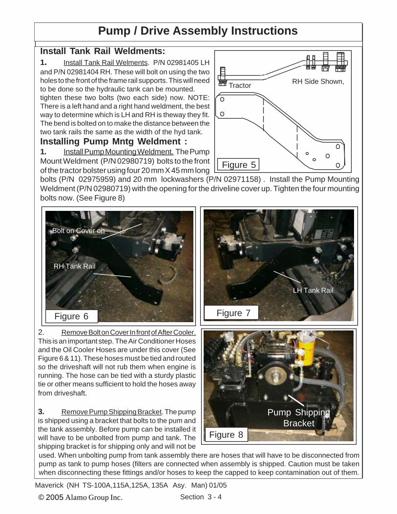
bolts (P/N 02975959) and 20 mm lockwashers (P/N 02971158) . Install the Pump MountingWeldment (P/N 02980719) with the opening for the driveline cover up. Tighten the four mountingbolts now. (See Figure 8)
Pump / Drive Assembly InstructionsInstall Tank Rail Weldments:1. Install Tank Rail Welments. P/N 02981405 LHand P/N 02981404 RH. These will bolt on using the twoholes to the front of the frame rail supports. This will needto be done so the hydraulic tank can be mounted.tighten these two bolts (two each side) now. NOTE:There is a left hand and a right hand weldment, the bestway to determine which is LH and RH is theway they fit.The bend is bolted on to make the distance between thetwo tank rails the same as the width of the hyd tank.Installing Pump Mntg Weldment :1. Install Pump Mounting Weldment. The PumpMount Weldment (P/N 02980719) bolts to the frontof the tractor bolster using four 20 mm X 45 mm long
2. Remove Bolt on Cover In front of After Cooler.This is an important step. The Air Conditioner Hosesand the Oil Cooler Hoses are under this cover (SeeFigure 6 & 11). These hoses must be tied and routedso the driveshaft will not rub them when engine isrunning. The hose can be tied with a sturdy plastictie or other means sufficient to hold the hoses awayfrom driveshaft.
3. Remove Pump Shipping Bracket. The pumpis shipped using a bracket that bolts to the pum andthe tank assembly. Before pump can be installed itwill have to be unbolted from pump and tank. Theshipping bracket is for shipping only and will not be
Figure 5
123123123123123
123123123123123
123123123123
12121212
111212
RH Side Shown,Tractor
Figure 6
RH Tank Rail
Bolt on Cover on
Figure 7
LH Tank Rail
Figure 8
Pump ShippingBracket
used. When unbolting pump from tank assembly there are hoses that will have to be disconnected frompump as tank to pump hoses (filters are connected when assembly is shipped. Caution must be takenwhen disconnecting these fittings and/or hoses to keep the capped to keep contamination out of them.

© 2005 Alamo Group Inc. Section 3 - 5Maverick (NH TS-100A,115A,125A,,135A Asy. Man) 01/05
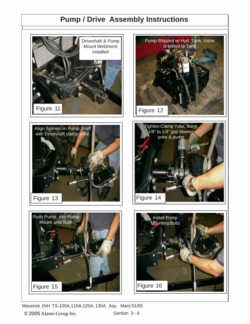
Installing Pump to Pump Mount Weldment :1. Install Pump to Pump Mount Weldment. The Pump has the tube half of driveline attachedand clamp yoke tightened. To install the pump and driveline half it is best to use an assistant oroverhead hoist to help you align the drivelines halves as they are slid together, the Driveline mustbe timed (universal joints aligned the same) as shown in the pump & driveline schematic on (SeeFigure 10 thru 17). Slide Driveline half and pump together until the shoulder on the pump slidein the hole on the pump mount weldment.
When installing the pump always keep ports sealed to keep them clean and free ofcontamination. The pump MUST be turned correctly. This can be done by making certain that thepressure filter that is mounted on top of the pump is up.
Install the two 1/2" X 1-1/2" long pump mount bolts (P/N 02892000) and two 1/2"lockwashers (P/N 00001300). Tighten the two pump mounting bolts.
Pump / Drive Assembly InstructionsInstalling Driveline Half to Pump :1. Install Driveline Half to Pump. Install the clamp yoke of the tube half of driveline onto thepump, slide the clamp yoke on pump shaft until you have about 1/8" to 1/4" gap between yokeand pump. Do not install yoke so far on pump shaft that yoke will rub against pump in anyway.Tighten the two bolts and nuts on clamp yoke at this time. (See Figure 9 & 14)
123456123456123456123456
1212121212121212
1212121212121212
Figure 9 Driveline Tube Half withClamp Yoke
11
11
Pump Mntg Bolts
P/N 02980666 PumpMount Weldment
Figure 10
12345678901123456789011234567890112345678901
123456789012123456789012123456789012123456789012 Mounting Bolts
Bolts ToTractor Bolster
123456789123456789123456789123456789
Mounting Bolts
12341234
12121212121212
1212121212121212
Install Pump Driveline cover here
1
1
© 2005 Alamo Group Inc. Section 3 - 6Maverick (NH TS-100A,115A,125A, 135A Asy. Man) 01/05
Pump / Drive Assembly Instructions
Install PumpMounting Bolts
Tighten Clamp Yoke, leave1/8" to 1/4" gap btween
yoke & pump
Align Splines on Pump Shaftwith Driveshaft clamp yoke.
Push Pump into PumpMount until flush
Driveshaft & PumpMount Weldment
installed
Figure 11
Figure 13 Figure 14
Figure 15 Figure 16
Pump Shipped w/ Hyd. Tank, Valveis bolted to Tank
Figure 12

© 2005 Alamo Group Inc. Section 3 - 7Maverick (NH TS-100A,115A,125A,,135A Asy. Man) 01/05
Pump / Drive Assembly Instructions
Pump EndClamp Yoke
Tractor Engine Pulley
1234512345
Pulley Adpater w/ MountingBolts & Washers (4 bolts)
Driveline Asy
4 Driveline Mounting BoltsP/N 02980398Driveline Cover
Time Universal Joints
123123123123123123
Driveline Cover Mounting Bolts,Flatwashers & Lockwashers (4)
12341234
Pump MountingBolts
P/N 02980666 PumpMount Weldment
Figure 17
Pump (Reference)
123456789012123456789012123456789012123456789012
12345678901123456789011234567890112345678901
Mounting Bolts
Bolts ToTractor Bolster
123456789123456789123456789123456789
Mounting Bolts
12341234
1212121212121212
11111111
1
1
Installing Pump Driveline Cover :1. Install Pump Driveline Cover. The Pump Driveline will have a cover (P/N 02980398) whichretained by four 1/4" X 3/4" bolts (P/N 00021400), four 1/4" flatwashers (P/N 00024100) and four1/4" lockwashers (P/N 00017000), install and tighten these now (See Figure 6).

© 2005 Alamo Group Inc. Section 3 - 8Maverick (NH TS-100A,115A,125A, 135A Asy. Man) 01/05
Pump / Drive Assembly Instructions
Install Tractor Guards & Covers:
1. Reinstall LH Side Engine Guards. The lefthand side engine guards need to be reinstalledusing the original hardware (See Figure 18). Theseguard are to gain access so the pulley adaptercould have been installed as shown (See Figure19).
2. Reinstall Top Cover. There is a top coverthat bolts onto the front of the tractor that isremoved to make certain that the hoses that rununderneath (See Figure 20) are tied back toprevent them from rubbing on the driveshaft thatwas installed, this is very important to preventdamage to the hoses (See Figure 21). The frontcover plate will be installed using the originalhardware.
3. Install Pump Mount Driveshaft Cover. ThePump Mount has a bolt on cover on top of it (SeeFigure 17 & 21). The cover and bolts are furnishedwith kit. In figure 21 is shown without pump in-stalled, this is for illustration only. Do not installcover before pump is installed.
4. Review this section and make certain allcomponents are installed and tightened to speci-fication (Bolt Toque Chart) and hoses are se-cured so as not to interfere with another compo-nent.
Figure 18
LH Side EngineGuards Removed
From Tractor
Figure 19
Air Conditioner &Oil Cooler Hoses
Figure 20 Figure 21
Air Conditioner &Oil Cooler Hoses
Front Cover
PumpMount
Cover BoltsHere

© 2005 Alamo Group Inc. Section 4 - 1
Maverick (NH TS-100A,115A , 125A, 135A Asy. Manl) 01/05
MAVERICKNew Holland Tractor
TS-100A, 115A, 125A, 135A
Hydraulic Tank &Control Valve
Installation
Section 4

© 2005 Alamo Group Inc. Section 4 - 2
Maverick (NH TS-100A,115A, 125A, 135A Asy. Man) 01/05
Hydraulic Tank & Control Valve Installation
Hydraulic Tank and Control Valve installation: This Section covers the installation of the Hydraulic Tank and Control Valve Assembly. The Tankand valve are shipped as an assembly.1. Locate Tank and Valve Asy, this will need to be lifted with a hoist, the front bumper wldmnt
is welded to the front of the tank from the factory.2. All Tools, Work Area, Components and Workers Hands must remain Clean when working on any
part of the Hydraulic System. All hoses and fittings should remain plugged till ready to install themto keep them clean.
3. All components should be rechecked for tightness and Hose routing also double checked.
2. Install Hyd. Tank & Control Valve Asy. Toinstall the tank and valve assembly you shoulduse an over head hoist to lift Tank and ValveAssembly, as it is heavy and can be damaged ifdropped. The hoist will also assist when aligningthe mounting holes. There are three mountingtabs in the rear of the tank. Mount the three rearbolts, Three on each side. The hydraulic tankslide under pump and between the LH & RH Tankrails. Do not remove from hoist until tank has beenbolted on and bolts tightened
3. Rotate Fittings to make better access toValve and tank connections, The fittings in thepump and valve may have to be rotated to makeit more accessable whenconnecting the hoses.
Install Hydraulic Tank to Front of Tractor:1. Hydraulic Tank and Valve Assembly, The Hydraulic Tank, Control Valve and Pump are shippedtogether (See Figure 1). The Pump should have already been mounted.
InnerMounting
Tabs
Figure 1
Hose Connections To Pump And Hyd Tank: (See Figure 2)Item Part No. Qty. DescriptionA 02981427 1 Hose, 8FJX - 8FJX 90° - 24" Lg. w/Red Tie (Charge Filter to Pump)B 02981428 1 Hose, 8FJX - 8FJX 90° - 21" Lg. w/ Blu Tie (Case Drain to Tank)C 02981429 1 Hose, 12FJX - 12FJX - 23" Lg. (Pump to Suction Filter) hose under
pump and cannot be seen in drawing.D 02981430 1 Hose, 12FJX - 12FJX - 31" Lg. w/ Red Tie (Pressure Filter to Supply)E 02981431 1 Hose, 4FJX - 4FJX 90° - 35" Lg. w/ Red Tie (Pump Load Sense to Valve (PX)
Connects to top side of pump as shown.F 02981432 1 Hose, 4FJX - 4FJX 90° - 20" Lg. w/ Blu Tie (Pump Regulator to Tank)
Connects to bottom side of pump not seen.F ------------- 1 Hose #4, Connects here w/ Tee Fitting (Connect to Base End Stabilizer Cyl)G 02981433 1 Hose, 20FJX - 12FJX - 24" Lg. (Pump to Suction Filter)H 02981462 1 Hose, 12FJX - 12FJX 90° - 20" Lg. w/ Org Tie (Valve Return to Tank)J ------------- 1 Hose, # 16 w/ Red Tie (Pressure from Pump to Motor) Bottom PortK ------------- 1 Hose, # 16 w/ Orange Tie (Oil Return from Motor) Top PortL ------------- 1 Hose. w/ Blue Tie (Oil Return from Oil Cooler to Tank)

© 2005 Alamo Group Inc. Section 4 - 3
Maverick (NH TS-100A,115A , 125A, 135A Asy. Manl) 01/05
NOTE: Hoses are not shown in drawing above, this is for clarity. The hose routing is for the hoses whichconnect from one point to the other. Use the instructions and hose description listed to follow hoserouting.Example: Hose - A connects to one end marked A and the other end of hose connects to the other itemmarked A. This is done with the other letters as well, the hose must connect to the same letter markingson each end as in drawing. Some hose will be marked with a colored plastic tie.Some hose will have a straight fitting or a 90° fitting. This is to allow hoses to be routed to where theyclear other items, when connecting hose put the end on that has the correct fitting as noted in drawingwith (90°) or the straight fitting if note marked hose routing that is to make hoses clear other items. DoNot connect hose to different letter items, all hose end must connect to the same letter on both ends.TO ID HOSES: Always check Size, Length, Fittings and Color Plastic Tie to identify the hoses. Somehoses will have the same color tie but the size, length or fittings will be different.
Hydraulic Tank Hose Routing
"A" # 8 Hose(Red Plastic Tie)
"G" # 20 HoseSuction Hose
(No Plastic Tie)
"A" # 8 Hose(90° Elbow)
(Red Plastic Tie)
"B" # 8 Hose(Blue Plastic Tie)
"B" # 8 Hose (90° Elbow)
(Blue Plastic Tie)
"G" # 20 HoseSuction Hose
(No Plastic Tie)
"C" # 12 HoseSuction Hose
(No Plastic Tie)
"J" # 16 Hose(Red Plastic Tie)
"K" # 16 Hose(Orange Plastic Tie)
"D" # 12 Hose(Red Plastic Tie)
"L" # Hose(Blue Plastic Tie)
"H" # 12 Hose(Orange Plastic Tie)
"H" # 12 Hose(90° Elbow)
(Orange Plastic Tie)
"D" # 12 Hose(Red Plastic Tie)
"E" # 4 Hose(Red Plastic Tie)
"F" # 4 Hose(90° Elbow)
(Blue Plastic Tie)"E" # 4 Hose (90° Elbow)
(Red Plastic Tie)
"F" # 4 Hose & TeeTank Return
(Blue Plastic Tie)
Figure 2

© 2005 Alamo Group Inc. Section 4 - 4
Maverick (NH TS-100A,115A, 125A, 135A Asy. Man) 01/05
Directional Control Valve Fittings
Pump PressurePort
Tank Return Port
"A"Ports
"B"Ports
FIGURE 3

© 2005 Alamo Group Inc. Section 4 - 5
Maverick (NH TS-100A,115A , 125A, 135A Asy. Manl) 01/05
Valve Fittings and Location: (See Figure 3)
Item Part No. Qty Description02981888 -- Valve & Fittings Asy, 6 Spool
1 02981370 1 Valve Asy w/o Fittings2 02090800 2 Adapter Hyd, Elbow 12MB - 12MJ 90°3 02972177 11 Adapter Hyd, Straight 10MB - 6MJ4 03200284 1 Adapter Hyd, Straight 6MB - 4MJ5 02981889 1 Adapter Hyd, Straight 10MB - 6MJ6 02972208 1 Valve Solenoid Asy7 02975438 1 Adapter Hyd, Straight 8MB - 8FJX8 02981890 1 Adapter Hyd, Straight 8MB - 6MJ
Directional Control Valve Fittings
HYDRAULIC LOCK VALVE: (Head Tilt Function)An Electric Solenoid Operated Hydraulic Lock Valve (Figure 4) is incorporated in the Head TiltFunction to prevent excessive (Head Lift Cylinder) leak down during storage or transportation.The Solenoid which operates this valve is normally in the Locked position until Head Loweringfunction is actuated at Joystick. When Joystick is actuated to lower Head an electric signalis sent to solenoid to open Lock valve. When the function to raise the Head is activated thereis no electric signal from Joystick. The pressure against the valve when head is being raisedwill force Valve open like a relief Valve allowing Oil to pass through it. If this valve will not openit could stop head from lifting or dropping. The valve is plumbed into the Hydraulic Circuitry ofthe Head Tilt Function and is located near the Control Valve.
Hydraulic Lock ValveItem Part No. Qty. Description
02972208 -- Solenoid Valve Asy1 02971425 1 Seal Kit, f/ solenoid Valve2 02975198 1 Coil, 12V- DC w/Dual
8-32NF Studs3 02975199 1 Cartridge, Solenoid Valve4 02975438 1 Adapter Hyd, Straight 8MB-6FJX5 02981890 1 Adapter Hyd, Straight 5MB - 6MJ
FIGURE 4

© 2005 Alamo Group Inc. Section 4 - 6
Maverick (NH TS-100A,115A, 125A, 135A Asy. Man) 01/05
HYDRAULIC HOSE CODES AT VALVEHydraulic Hose Band Mark Color Codes: Hose's and/or fittings are marked with a
Color Coded Plastic Band around it. Some Bands are a solid Color and some are Colored with aStripe. The purpose of the colored bands are to provide a quick reference for hose and portconnection. A metal band is also attached to the hose, on that band is an Alamo Industrial PartNumber for reference if needing a replacement hose. Always Check Hose Size, Color Code& Part Number (See Figure 5)Boom Cylinder Circuit Hoses:Color Tie (Code) Hose Size Port Diverter Hyd. FunctionGreen G SAE # 6 A --- Swing, Back (Rod End)Green / White G/W SAE # 6 B --- Swing, Forward (Base End)Orange OR SAE # 6 A --- Lift, Down (Rod End)Orange / White OR/W SAE # 6 B --- Lift, Up (Base End)Blue B SAE # 6 A --- Dipper, In (Rod End)Blue / White B/W SAE # 6 B --- Dipper, Out (Base End)Yellow Y SAE # 6 A --- Telescope, In (Rod End)Yellow / White Y/W SAE # 6 B --- Telescope, Out (Base End)Red R SAE # 6 B --- Head Tilt, Up (Rod End)Red / White R/W SAE # 6 A --- Head Tilt, Down (Base End)Green G SAE # 4 A P2 Control Valve tor Diverter valveGreen / White G/W SAE #4 B P1 Control Valve to Diverter ValveGreen G SAE # 4 --- C4 Swivel, CW (Rod End)Green / White G/W SAE # 4 --- C1 Swivel, CCW (Base End)Yellow Y SAE # 4 --- C3 Door, Open (Rod End)Yellow / White Y/W SAE # 4 -- C2 Door, Closed (Base End)Orange OR SAE#12 T --- Valve Return To TankRed R SAE#12 P -- Pressure to Valve.
Motor Circuit Hoses to Boom Connections: (Listed as reference)Color Tie (Code) Hose Size Hyd. FunctionRed R SAE # 16 -- Pressure Flow to MotorOrange OR SAE # 16 -- Return Flow From MotorBlue B SAE # 8 -- Case Flow From Motor to BoomBlue B SAE # 12 -- Case Flow at Boom to Tank
Hydraulic Hose Connections
Diverter Valve.:The Diverter Valve bolts onto the front frame mount bracket on the LH side of the tractor, the holes
are in the bracket (See Figure 5 , 6 & 7). The Diverter valve is a electrical operated valve that allows thehydraulic pressure to be shared to operate two (or more if valves are stacked) functions with a singlepressure supply. This valve is strictly a diverter valve and is designed to direct the pressure, not regulatethe flow or pressure.
The Port openings on this diverter valve are marked with letter number codes which show whichport is connected to which hose and where that hose connect on other end (See Figure 5, 4 & 7))Port Function & ConnectionP1 Hose Hydraulic Pressure from Door / Swivel (B) Port on Control Valve (G/W Tie)P2 Hose Hydraulic Return to Door / Swivel (A) Port on Control Valve (G Tie)C1 Hose to Head Swivel Cylinder Base End (G/W Tie)C2 Hose to Door Cylinder Base End (Y/W Tie)C3 Hose to Door Cylinder Rod End (Y Tie)C4 Hose to Head Swivel Cylinder Rod End (G Tie)

© 2005 Alamo Group Inc. Section 4 - 7
Maverick (NH TS-100A,115A , 125A, 135A Asy. Manl) 01/05
Hydraulic Hose Connections
VS . 125/F
C2
C3SA
E 4
P1P2
Valve "B" Port toDiverter valve P1 Port
(G/W Tie)
Valve "A" Port toDiverter valve P2 Port
(G Tie)
4 Through holes aremounting holes
Diverter Valve "C1" Portto Swivel Cyl BaseEnd Port (G/W Tie)
Diverter Valve "C4" Portto Swivel Cyl Rod End
Port (G Tie)
Diverter Valve "C2" Portto Door Cyl Base End
Port (Y/W Tie)
Diverter Valve "C3" Portto Door Cyl Rod End
Port (Y Tie)
Diverter Valve
FIGURE 5
PressureSupplyPort "P"
ReturnTo Tank
"T"
"B"
"A""A""A""A""A""A"
"B""B""B""B""B"
Sw
ing
Lift
Tele
scop
e
Hea
d Ti
lt
Hea
d Sw
ivel
/ D
oor
(To
Div
erte
r Va
lve)
Dip
per
G
G/W
OR R/W
Y/WB/WOR/W
Y
R
B
G/W
G
Six Spool Control ValveExternal Wire Connec-tions for valve are marked"A" and "B" on Valve &AA1 thru AA12 on wireharness connections
A A11
A A12
B
A
A A9
A A10
B
A
A A7
A A8
B
A
A A5
A A6
B
A
A A3
A A4
B
A
A A2
A A1
B
A

© 2005 Alamo Group Inc. Section 4 - 8
Maverick (NH TS-100A,115A, 125A, 135A Asy. Man) 01/05
Oil Cooler / Fan Assembly
Connecting Oil Cooler And Fan As-sembly to Exterior Wire Harness1. Oil Cooler / Fan Assembly. The Oilcooler / fan assembly is for cooling the oilbeing returned from the Motor Case Drain.The fan is connected to the control box and isturned on & off automatically. It set to run on aprogram that will run the fan in the coolingrotation for a designated time, then stop, re-verse the rotation (cycle to clean debris off ofcooler, then stop and reverse the fan againand begin the cycle all over again.
The connection to the cooler on theexterior wire harness is marked with code R1.The connection from the fan will have twowires, a Blue (+ connection) and a black (-connection) (See Figure 8).
Exterior wire harness con-nection marked R1 connects
here
FIGURE 8
Swivel Cyl. Base End C1 Port (G/W Tie)
Swivel Cyl. RodEnd C4 Port (G Tie)
Door Cyl. Rod EndC3 Port (Y Tie)
Door Cyl.Base EndC2 Port
(Y/W Tie)Valve "A" Port toP2 Diverter Port
Port (G Tie)
From Valve "A"Port to P1 Diverter
Port (G / WTie)
FIGURE 6
FIGURE 7
Diverter Valve
FIGURE 9

© 2005 Alamo Group Inc. Section 5 - 1
Maverick (NH TS-100A,115A,125A,135A Asy. Man) 01/05
Maverick BoomNew Holland Tractor
TS-100A,115A,125A & 135A
Battery ModificationExhaust Modification
Fuel Tank ModificationMain Frame Installation
Section 5

© 2005 Alamo Group Inc. Section 5 - 2
Maverick (NH TS-100A,115A ,125A,135A Asy. Man) 01/05
Battery Holder Relocation:1. The Battery Relocation. The battery holder islocated on the RH side of the tractor (See Figure 1) .It will have to be relocated. The mount kit will includea battery relocation kit. The battery relocation kitincludes a mounting bracket (See Figure 2) that willrelocate the battery tray farther to the rear. This isdone so the Boom Swing will not hit battery when inthe transport position. The RH Step Will need to beremoved to allow access to relocate battery.
2. Remove Factory Battery Cover, Battery,Battery Tray and Battery Tray mount. Remove thebattery cover (See Figure 3), Remove the batterycables from the battery. Remove the battery fromthe battery tray. Unbolt the battery tray from thetractors factory mount bracket. Remove the factorymounting bracket from the tractor (See Figure 4).
3. Install Replacement Battery Tray Bracket.Install the replacement battery tray bracket (SeeFigure 2) using the same bolts and holes as theoriginal bracket. This Bracket is designed to movebattery further back. Install original battery tray usingoriginal hardware. Reinstall battery into batter tray(See Figure 3). DO NOT reconnect battery cables atthis time, leave them off and make certain they donot make contact with the battery connections asyou do not want the battery connected during instal-lation. Replace the battery cover (See Figure 1) fornow this will protect battery and cover.
Figure 1
Figure 2
BatteryRelocation
BracketP/N
02981725
Figure 3 Figure 4
Battery Holder Relocation

© 2005 Alamo Group Inc. Section 5 - 3
Maverick (NH TS-100A,115A ,125A/,35A Asy. Man) 01/05
Exhaust / Muffler Relocation
Exhaust / MufflerRelocation:1. Remove The Exhaust . The Exhaust reloca-tion kit will include a new mounting bracket, Boltinghardware, replacement exhaust pipe from turbo tomuffler. The Muffler needs to be removed first (SeeFigure 5). Remove the Exhaust pipe to turbo (SeeFigure 5). Remove the tractors factory Exhaust pipemounting bracket (See Figure 6).
2. Install Exhaust Replacement MountingBracket. The replacement exhaust mountingbracket will bolt in the place of the factory mountingbracket. The replacement bracket moves the ex-haust inward towards the engine by about 5 to 6inches. This is to give clearance of the boom andexhaust system (See Figure 7).
3. Install Replacement Exhaust Pipe. Installthe replacement exhaust pipe using the new clampfurnished in kit. Fasten the new exhaust pipe to thenew exhaust bracket using the two factory u-Boltsthat were used on the original exhaust pipe (SeeFigure 8).
4. Reinstall the muffler to the exhaust pipe us-ing the factory bolts and hardware. Check all thebolts and components to the exhaust for tightnessand fit.
Figure 5
Tractor FactoryExhaust pipe to
Turbo
Figure 6
Factory ExhaustMount Bracket
Figure 7 Figure 8Replacement
Exhaust BracketP/N 02980933
New Exhaust PipeP/N 02980917

© 2005 Alamo Group Inc. Section 5 - 4
Maverick (NH TS-100A,115A ,125A,135A Asy. Man) 01/05
Fuel Tank Replacement
Fuel Tank Replacement:1. Remove RH Rear Tire and Wheel. Useproper Floor jack to lift the RH Rear Wheel, Supportthe tractor with proper jack stands rated appropri-ately for the tractors weight. The RH rear tire andwheel should be removed for this installation byusing a hoist to support and lift the wheel and tireassembly. The tractors factory fuel tank is mountedbehind the RH rear tire and wheel (See Figure 9).
2. Remove Tractors Factory Fuel Tank andMounting Brackets. The LH factory step will have tobe removed from the tractor before attempting toremove the fuel tank, the step will not be reused.The factory fuel tank will need to drained of fuel. Usean appropriate and safe method for pumping outtank and for the storage of the fuel removed. TheTank is removed by loosening and removing theretaining straps that you will see around the tankfrom the out side. DO NOT Attempt to remove tankwith fuel in it.Store the fuel tank in an appropriate safe place awayfrom flames, extreme heat and or dusting dirtyconditions. The Fuel Pickup and Gauge sending unitwill need to be removed from the factory tank to beinstalled in the new replacement tank later (SeeFigure 10).
3. Install Replacement Fuel Tank MountingBrackets. Remove the factory fuel tank mountingbrackets, there are two new mounting brackets thatwill be supplied to mount the new tank. There is afront and a rear bracket (See Figure 11 & 12).
Figure 9
Remove RHRear Tire &
Wheel
Figure 10
Figure 11 Figure 12
Front Fuel TankBracket P/N02982206
2HolesHere
1HoleHere
Rear Fuel TankBracket P/N02982207

© 2005 Alamo Group Inc. Section 5 - 5
Maverick (NH TS-100A,115A ,125A/,35A Asy. Man) 01/05
4. Install Pick Up Tube & Gauge Sending Unit innew Tank. The Pickup gauge sending unit from thefactory tank will be installed into the new tank. This isrecommended to be done before mounting the newtank to the tractor (See Figure 13). The new tank willhave a fuel capacity of 51 gallons
5. Install the new mount brackets to the tractorframe. The tank mounting brackets will bolt to thetractor the same as the factory brackets that wereremoved. Make certain that the brackets are in-stalled correctly, the front bracket will have 2 outerholes (same as the tank see Figure 11 & 13). Therear bracket will have 1 hole in the outer end (sameas the tank, See Figure 12 & 13)
6. Install The new Fuel tank onto Tractor. Thenew fuel tank with the gauge sending unit slide in ontop of the new mounting brackets with the fuel cap tothe front (See Figure 14). Connect lines to fuel pickup connections, connect wiring to fuel gauge send-ing unit. (See Figure 14)
7. Bolt Tank to the Mounting Brackets. Bolt thetank to the mounting brackets, there are two bolts inthe front bracket and one bolt in the rear bracket.(See Figure 15)
8. Install New replacement Step. The new Re-placement step is a bolt on weldment that will bolt tothe new fuel tank with four bolts, note: below thestep is painted yellow for clarity only (See Figure16).
Figure 13
Pick Up Tube UnitFront
Rear
MountingTabs
Tank P/N 02982198
Figure 14
FrontBracket(2 Bolts)
RearBracket(1 Bolt)
Figure 15 Figure 16
Fuel Tank Replacement

© 2005 Alamo Group Inc. Section 5 - 6
Maverick (NH TS-100A,115A ,125A,135A Asy. Man) 01/05
Under Mount frame Asy:
1. Before beginning any repairs on this section make certain the boom is extended outward tofull extend and laying on the floor. Before removing the Boom Pivot Pin support the boom with anoverhead hoist so as when Pie is removed boom can be lifted out of the way. NEVER REMOVE ANYPINS OR BOLTS unless boom is supported at pivot end and head end is resting on the floor.
2. The under mount frame asy is made up of the Turret, Center Section Frame Weldment,Boom Mount, Swing Cylinders, Swing Cylinder Trunnion Mount, Turret Cylinder Link and CounterWeight.
3. The Turret Asy will be shipped assembled to the Boom mount with the hoses and cylindersplus attaching hardware assembled to it.
4. The Swing Cylinders have replaceable mounting bushing which can be replaced byremoving the bottom cover and trunnion mount weldment. The Cylinders can be dropped downenough to replace the bushing. The replace the Trunnion Mount weldment. Also by removing thecylinders the Turret Cylinder link can be removed.
5. The Turret assembly has a large bearing assembly bolted to it and then bolted to the BoomMount. This Bearing CANNOT be removed (or replaced ) unless the Boom is disconnected from itfirst. When disconnecting boom make certain the boom is supported as not to fall (See Step 1). TheBolts retaining the turret to the bearing and the bolts connecting bearing to the Boom Mount MUSTbe torqued to the required specification, This is very critical. See the Bolt Torque Chart in thebeginning of this manual.
6. DO NOT remove any mount pins and/or bolts unless the components are supported properlyto prevent them from falling
7. The Turret Bearing Assembly has 3 grease fittings, each 120° apart. All three of these greasefittings must be greased because of the diameter of the bearing this to ensure an even distributionof grease though out the diameter of the bearing assembly.
8. If the hoses for the swing cylinders are disconnected or replaced make certain that they arereconnected correctly as shown in this section (Swing Cylinder Hose Routing). If the hoses are notconnected correctly the swing will not function correctly.
Frame Installation

© 2005 Alamo Group Inc. Section 5 - 7
Maverick (NH TS-100A,115A ,125A/,35A Asy. Man) 01/05
Frame Installation
Under Mount Frame Asy(24 & 30 ft are the same except for the LH weight) 30 ft model only
Swing CylindersSwing Cylinder Pivot Bushings
Swing Cylinder Trunnion Mount Weldment
Swing Cylinder Cover
Turret Cylinder Link
Boom Mount, Machined
Boom Mount Attaching Pin, Short Pin
Boom Mount Attaching Pin, Medium Pin
Boom Mount Attaching Pin, Long Pin
Lift Cyl Pin
Turret / Boom Mount Pin
Turret Asy, Machined
LH Counter Weight
Weight Attaching Pin, Long Pin
Center Section Frame Weldment

© 2005 Alamo Group Inc. Section 5 - 8
Maverick (NH TS-100A,115A ,125A,135A Asy. Man) 01/05
Frame Installation:
1. Frame Components. The frame will includethe rear axle mounts, a LH & RH Frame rail. Twofront frame mounts, a LH & RH. One center frameweldment. (See Figure 17, 18, 19, 20 & 21)
2. Install Frame Components. The Framecomponents will only fit one way. The Frame com-ponents are a Bolt together assembly no weldingwill be required. The Frame components will bolttogether and to the tractor using mostly 3/4" and/or20 mm bolts. Each 3/4" & 20 mm bolt will usehardened flat washers, one on the head side whenbolts go into the tractor castings. Two washersused when bolts use a nut and go through theframe. These hardened washers are important.
Frame Installation
Figure 17
Figure 18 Figure 19
Figure 20 Figure 21
Center FrameWeldment
P/N 02981168
LH Front FrameMount Weldment
P/N 02982014
RH Front FrameMount Weldment
P/N 02982015
RH Rear FrameMount Weldment
P/N 02982005
LH Rear FrameMount Weldment
P/N 02982006

© 2005 Alamo Group Inc. Section 5 - 9
Maverick (NH TS-100A,115A ,125A/,35A Asy. Man) 01/05
Frame Installation
3. Install Rear Frame Mount Rails. Rear framerails consist of a LH & RH. We have started with theLeft Hand Rail. The three point lift stabilizer bracketswill need to be unbolted on both sides. In the illustra-tion for the LH side we installed the frame with theLH rear tire and wheel still removed, this was donefor clarity not because the wheel needs to be re-moved. Using a floor jack to lift the rail up under therear axle (Stabilizer brackets for three point havebeen unbolted). Install the bolts up and into the threepoint stabilizer bracket and the tractors rear axlehousing and snug the bolts down. Support the framerail with a jack stand (or leave the floor jack under it).(See Figure 17 & 22).
The RH Rear Frame Rail will basically installthe same, bolts up under the tractor axle housingwith the three point stabilizer bolt back up underframe rail (See Figure 18 & 23). The RH Rail looksdifferent at the rear because the boom rest will bolthere later.
4. Install Front Frame Mount Rails. The FrontFrame mount rails will consist of a RH & LH (SeeFigure 19, 20, 24 & 25) These will only fit one way asthey have a gusset reinforcement on one side thatwill be showing to the outside when installed. Thesecan be lifted by the technician installing them. TheLH and RH will install the same way, Using 4 boltseach that screw into tractor casting on the side ofthe tractor (See Figure 24). Make certain that all 3/4"and 20 mm bolts have hardened flatwashers onthem.
Figure 22
LH Rear FrameMount Weldment
P/N 02982006
Figure 23
RH Rear FrameMount Weldment
P/N 02982005
3 Point Stabi-lizer Bracket
Figure 24
RH Front FrameMount Weldment
P/N 02982015
Figure 25
LH Front FrameMount Weldment
P/N 02982014

© 2005 Alamo Group Inc. Section 5 - 10
Maverick (NH TS-100A,115A ,125A,135A Asy. Man) 01/05
5. Install Center Frame Weldment. The Center Frame Weldment has a front and a back side (LH& RH side). The Center frame must be installed with the two openings (See Figure 26) toward the frontof the tractor. These openings are to allow for the movement of the swing cylinders when moving theboom to the boom rest position.
IMPORTANT NOTE: When bolting the center frame up to the front and rear frame mountingrails the bolts on the RH turret side must have the bolts installed from the bottom with the bolt heads onbottom under center under frame and the nuts on top (See Figure 27 showing nuts on top). The reasonthe nuts must be on top is so the bolts will not hit the swing cylinders when the turret assembly has beenmounted. The Bolts that are used to mount center frame are not the same lentgh. The 8 bolts for the rearfame bracts (bolts that face the rear of the tractor) will be 3/4" X 3-1/2" long. The other twelve bolts will be3/4" X 2-1/4" long. All 20 Bolts that at are used to mount center frame MUST have hardened flat washersinstall on both sides, one under Bolt Head and one under Nut (See Figure 26 & 27)
Using floor jacks (or Fork lift) position the center frame weldment up under the tractor (See Figure27). The center frame weldment will bolt to the front and rear mounting rails on both sides. Make Certainto use hardened flatwashers on all 3/4" and 20 mm bolts, when using nut on bolts it will need twohardened washers, one on each side (See Figure 27) . Double check the frame mounting bolt tightness.
P/N 02981168 Center Section Under Mount Frame Wldmnt
Rear View
Front ofTractor
LH Side ofTractor
RH Sideof Tractor
Rear ofTractor
Install with theseopenings to front of tractor
Figure 26
6. Install Boom Rest Weldment. The boom rest weldment for the 24 foot boom and the 30 ft.boom are not the same (See Figure 29). The boom rest weldment bolts to the RH Side on the RearFrame mount weldment behind the tractor axle weldment (See Figure 30). It is recommended that thisbe installed using an overhead hoist and supported by the hoist until boom rest and support brace(See Figure 28 & 30) are completely installed. The Boom Rest Support also serves as the top axlestrap for the RH Axle mount (See Figure 30).
Rear Mounting Holes use 3/4" X3-1/2" bolts in these 8 places
Front MountingHoles use 3/4" X
2-1/4" bolts inthese 8 places
Rear Top Mounting Holes use 3/4" X 2-1/4" bolts in these 4 places
Frame Installation

© 2005 Alamo Group Inc. Section 5 - 11
Maverick (NH TS-100A,115A ,125A/,35A Asy. Man) 01/05
Frame Installation
Boom RestWeldment
P/N 02982314 (f/24 ft. boom)
&P/N 02982025 (f/ 30 ft. boom)
Figure 29
Figure 31Figure 30
7. Install LH Axle Strap. The Axle Strap boltsdown over the top of the Axle (LH Side) and bolts runthrough the Rear Frame rails. The RH Side the axlestrap is part of the boom support brace weldmentand also bolts down over the axle with the boltsthrough the rear frame rail (See Figure 30 & 31)
Make certain that all the bolts mounting theframe components and the boom rest are properlytorqued, see the bolt torque chart.
8. Reinstall LH Rear Tire and Wheel. Reinstallthe LH rear Tire and Wheel now if it has not alreadybeen done. Use a hoist to lift and secure the reartires is recommended as they are very heavy.
Figure 28
Boom RestSupport Weldment
P/N 02982022 (f/24 ft or 30 ft.. boom)
Bolts toboom rest
Bolts to top oftractor axle
LH side of tractor Upperaxle strap
P/N 02980694
Boom Rest
Boom Rest Support& Axle StrapWeldment
Figure 27
Shown from LHside of tractor
Rear
Front

© 2005 Alamo Group Inc. Section 5 - 12
Maverick (NH TS-100A,115A ,125A,135A Asy. Man) 01/05
Counter Weight Installation 24 & 30 Foot Boom:1. Counter Weight (CWT) Installation. The Counter weight (See Figure 1 ) mounts on the LH side UnderFrame Weldment. Its is retained with three pins, the long pin on top, the short pin at the rear and a shortpin at the front. Using a hoist or other sufficient lifting device align the weight with the frame. The Framefor the weight will slide over the under frame until the upper long pin is aligned with the mounting tube ofthe weight and the mounting tubes of the under frame. Install the long mounting pin. The front and rearpin holes should be aligned, install the short pins front and rear. The short pins are retained using a nutand bolt. The long pin uses two large cotter pins, install cotter pins and bend end of them to secure them.(See Figure 32 , 33 & 34)
2. Additional Counter Weight (CWT) Installation: The 30 foot boom model has an additional bolt on weightat the counter weight. This additional weight bolts to the weight weldment on the 30 foot model only (SeeFigure 32)
3. Wheel Counter Weight (CWT) Installation: The Wheel counter weight is in addition to the framemounted counter weight, they both must be used together, the 30 foot boom will have an additional framecounted counter weight bolted on, (See Figure 32). All these weight are in addition to adding liquid weightinto the Left rear tire. The proper amount of counter weight is not complete until all these weight have beeninstalled.
Additional bolt onWeight Used on30 ft boom modelsonly
LH Counter Weight 24 or30 Foot Boom
Weight Attaching Pin,Short Pin Rear side
Weight Attaching Pin,Short Pin front sideFigure 32
Frame Installation
Center SectionUnder FrameWeldment
Weight MountAttaching Pin,Long Pin

© 2005 Alamo Group Inc. Section 5 - 13
Maverick (NH TS-100A,115A ,125A/,35A Asy. Man) 01/05
Figure 34Figure 33
Frame Installation
Turret Assembly Installation 24 & 30 Foot Boom:1. Turret Assembly. Theturret assembly isshipped assembled with the hydraulic swing cyl-inders, hoses, pivot bearing assembly, boommount weldment and mounting pins installed(See Figure 35 & 36).
2. Under Frame Weldment. The Under frameweldment center section is designed for the turretassembly to mount on the RH side. Remove theone long mounting pin and the front and backshort mounting pins (See Figure 36 & 37). Checkto make certain the mounting bolts mounting thecenter ubder frame weldment are installed withthe bolt heads unter frame weldment and nuts areon top visible looking down, if they are in wrong theswing cylinders will hit the bolts causing damge tocylinders and bolts. (See Figure 37)
Figure 36Figure 35
Turret Attach-ing Pin, ShortPin, one Frontside and onerear side.
Center SectionUnder FrameWeldment
Turret MountAttaching Pin,Long Pin
Turret MountAttaching Pin,Long Pin

© 2005 Alamo Group Inc. Section 5 - 14
Maverick (NH TS-100A,115A ,125A,135A Asy. Man) 01/05
Figure 37 Figure 38
3. Turret Assembly Installation. Theturret assembly mounts on the RH side onto the center sectionunder frame (See Figure 36 & 37) . Using a hoist (or other lifting device) lower the turret assembly untilit is level with the underframe. Slide the turret assembly inward toward the under frame until the retainingpin tube on under frame an turret assembly align. Installthe long upper retaining pin and then the two smallfront and rear pins. The long upper pin is retained with two cotter pins that need to be bent over on theends. The short pins are retained with nuts and bolts (See Figure 36 & 38).
Frame Installation
4. Turret Assembly Grease Fittings. The turret assembly has three grease fittings around the OD ofit. The grease fittings are 120° apart, this is to make certain that the bearing will be greased all the wayaround because of the large diameter of the bearing. This bearing must be greased before unit is put intoservice. It is easier to get to grease fittings now than after boom has been installed. On the under sideof the turret assembly are the grease fittings for the swing cylinder pivot mounts, these need to begreased before operating the unit. Also there is a bolt on cover on the under side of turret that will beinstalled (See Figure 40) at a later time. Greasing the cylinder pivots will need to be done before the coveris installed (See Figure 39) and the boom swing stop will need to be adjusted, but this cannot be doneuntil a later time making it best to leave this cover of until then. After greasing components at assemblyof unit operator should consult the operators manual for maintenance requirements.
Figure 39 Figure 40

© 2005 Alamo Group Inc. Section 5 - 15
Maverick (NH TS-100A,115A ,125A/,35A Asy. Man) 01/05
Front Axle Stabilizer Installation - 30 FT Model (Standard)
This kit is tied to the oil supply at the Lift Cylinder forthe boom, the upper pressure supply hose (# 4 hose withblue plastic tie) is tee'd to the "B" port of valve for the liftcylinder and connected to the Base end of the stabilizercylinder. The lower Hose is connected to the rod end of thecylinder and is connected to the tank return hose at thetank. Install the cylinder with the rod end toward the axleand the base end of cylinder up to the bracket (item 3)bolted to tractor frame. Number 4 hose with a blue plastictie at the front side of tank (See Figure 41 through 48).
The Brackets bolt to the tractor axle and form aclamp around front axle housing (item 1 & 2). The Stabi-lizer cylinder is charged only when the boom lift cylinder isactivated and is controlled automatically with the boom liftcontrols.
The three axle brackets are as followsItem Part No Qty Description
1 02983143 1 Top Axle Bracket2 02983144 1 Bottom Axle Bracket3 02982330 1 Stabilizer Support Bracket4 02981316 1 Hydraulic CylinderSee Mount Kit & Component ID section for Axle Stabilizercomplete component and hardware kit list.2. When installed correctly the three componentsshould be aligned as show (See Figure 44). The upper andlower bracket should have the same gap between them infront as in the back to make certain brackets are even.Check the hose connections and all mounting bolts for theaxle stabilizer kit.
1212
123123123
1234123412341234
123456123456123456123456123456
P/N 02981316 Cylinder Assembly (Included in Front Axle Stabilizer Kit Only)
P/N 02982320 Cyl Sup-port Weldment (In-cluded in Front Axle Sta-bilizer Kit Only)
Figure 42
Figure 43
Pressure Hose End
Return Hose End
Axle EndSupport Bracket End
Front Axle Stabilizer Kit Installation:1. Install Front Axle Stabilizer Kit (Kit P/N 02981895). The front axle stabilizer kit is standard on the30 foot model. The front axle stabilizer kit will consist of all brackets and hardware to install to front RHside of 4 wheel drive axle RH side of tractor frame
P/N 02983143New front axlebracket (top)
P/N 02983144New front axlebracket (bottom)
Back side
RH FrontTire side
Engine side
Figure 41
1234123412341234
123456123456123456123456123456
121212
123123123
Upper CylMount Bolt
Lower CylMount Bolt
Upper Clamp Mount Bolt
Figure 44

© 2005 Alamo Group Inc. Section 5 - 16
Maverick (NH TS-100A,115A ,125A,135A Asy. Man) 01/05
NOTES

© 2005 Alamo Group Inc. Section 6 - 1
Maverick (NH TS-100A,115A , 125A, 135A Asy.Man) 01/05
MAVERICKNew Holland Tractor
TS-100A,115A,125A,135A
OptionalRH Lexan Door
Installation
Section 6

© 2005 Alamo Group Inc. Section 6 - 2Maverick (NH TS-100A,115A , 125A, 135A Asy.Man) 01/05
New Holland "TS" Series Optional Door Kit No. 02980888RH Lexan Door Kit. OptionP/N 02980888
Remove & Dis-Assembly of Factory StockGlass Door.1. To remove the factory door make certainthat you use enough help to remove it safely. It isrecommended to use three people as shown (seefigure 1) Use some type of container to hold allremoved components and hardware, some will bereused & some will not. The Assembly procedureand the dis-assembly procedure is the same exceptin reverse. The RH Door is a mirror image of the LHDoor which can always be used for reference.2. Disconnect the gas shock (it is inside) fromthe door pipe brace, disconnect it at the door end.3. With someone supporting the door at thebottom and some one to hold the nuts inside loosenthe upper hinge bolts and the lower hinge bolts (Seefigure 1) CAUTION! The lower hinge bolts also holdthe Pipe brace to the window, with these hinge boltsremoved DO NOT lift or hold window by using thisbrace, it could put glass window under stress caus-ing it to break. When Removing Bolts from hingesmake a note of the large rubber washer and the largesteel washer and there location as they will be reusedin the same location and order they are in. (SeeFigure 1).4. Lay Removed door on a soft protectedsurface for the disassembly of the latch and bracecomponents (See Figure 2). (Item 1) This is the
12
3
Figure 1
Figure 2
4 56
plastic cover for the latch and will snap off. (Item2) This is the Latch and retaining bolts, nuts & washers for the latch assembly, remove them. Whenremoving the latch you will need to lift and turn it in away that you can get the inside handle rod (connectedto item 5) pulled out of its hole in the latch not the handle item 5. (Item 3) Remove the upper retaining nutand flat washer (this flat washer will not be reused) (Item 4) Remove the lower handle retaining bolt , therewill be rubber washer (that will not be reused) under the steel washer. (Item 5) The outer door handle canbe removed now, there will be rubber pad at the upper (larger portion) end between the glass and thehandle that will have a thin pipe type spacer in it. Also the lower handle mounting bolt will have a smallerrubber pad with a metal insert in it that is between the glass and handle. (Item 6) This is the inner doorhandle and WILL NOT be removed from the pipe brace weldment. (Item 7) This is the pipe brace weldmentand extends from latch / door handle to the lower hinge bolts. At the lower hinge bolts there will be a rubberpad between glass and metal plate, this pad will be reused. (Item 8) This is the lower mount for the pipebrace (See Figure 4 & 5 for fastener) and will be the last fastener removed, this fastener takes a specialtool to remove it. See your New Holland Dealer for instruction & Removal Tool.
7
Optional Lexan RH Door Kit Installation

© 2005 Alamo Group Inc. Section 6 - 3
Maverick (NH TS-100A,115A , 125A, 135A Asy.Man) 01/05
5. Lay the New Lexan Door (P/N 02980803) on aprotected surface (here we used Bubble Wrap Packingmaterial). Install the push-on weather seal material (P/N 02980889) with the soft rubber side up as shown. Thisweather seal is designed to push-on with out adhesive,but you can use adhesive if you wanted. Where the twoend meet an adhesive should be used to jion the two end.Use an adhesve that is rubbery and dries to the touch.The 3M Co. makes a good Black weather strip adhesivethat will work well for this (See Figure 3)6. Install the pipe brace on top of door.( Item 8)This is the lower fastener (See Figure 4 & 5) and willneed to be installed first, make certain to put the rubberwasher back on fastener, install the fastener untill theshoulder of the fastener is into the hole in the door. DONOT Tighten Fastener at this time.7. Install Outer Door Handle and fasteners. (Item9) This is the outer door handle, before it can be installedItem 10 must be modified (Item 10) This is the uppermount of handle rubber pad. There is a shoulder on it thatmust be cut off before it can be used, using a sharp knifecut this shoulder off, The tube Spacer shown with item3 goes through the hole of item 10 and then slide overthreads of item 9.8. Push the lower rubber (with steel insert in it)into the hole of the door, holding the handle in place fronthe bottom start the bolt & washer item 4, there was arubber washer used under item 4 bolt. In some casesit can not be reinstalled, check bolt engage ment to seeif it can be used.
Figure 3The two endsmeet here
Figure 4
Figure 5 Figure 6
89
10
4
3
8
3
49
Inner LatchActuater Rod
Optional Lexan RH Door Kit Installation
New Holland "TS" Series Optional Door Kit No. 02980888

© 2005 Alamo Group Inc. Section 6 - 4Maverick (NH TS-100A,115A , 125A, 135A Asy.Man) 01/05
New Holland "TS" Series Optional Door Kit No. 029808889. Insert Handle into door from bottom, makecertain item 3 tube spacer is inserted through hole ofdoor and through hole of pipe brace, there is a rubberpad to reinstall between pipe brace plate at upperlatch and door (See Figure 6) Install item 3 Nut ontohandle, Note when disassembled there was a largeflat washer here. The flat washer WILL NOT be usedin reassembly. Snug the item 3 nut but DO NOTtighten.10. Lifting the Latch and turning to the correctangle slide the latch actuated rod through the hole onthe latch. Turn and lower latch in place. Using theoriginal Bolts, Washers and nuts bolt on the latch topipe brace (See Figure 7). These can be tightened atthis time.11. Prepare the Door Hinges which are still ontractor (See Figure 8) by making certain the roundrubber washers are in place, the ID of washer willhave the shoulder of the hinge sticking through it asshown (See Large Rubber Washers Figure 8). Thelower hinge uses a two hole oblong rubber padbetween door and pipe brace.12. Install new door, make certain all rubberpads are in place, Holding door push the lower hingeup to door. Install the new 5/16" NC X 1-3/4" Gr. 5Bolts P/N 00021900 from kit, Use the old small ODstructural flatwashers that were removed from origi-nal door. The Top Hinge on the inside will have around rubber washer pad and a large round steelwasher. The lower hinge should have the oblongrubber pad with two holes in it. Put the New 5/16" NClocknuts with any washers that were remove formoriginal door. While supporting the door (see Figure9) tighten the hinge mounting bolts, Do this slowlyand carefully making certain the shoulder oh hingegoes through hole in door. DO NOT over tight thesebolts. Tighten the other fasteners on the door braceand latch handle. If Door is not fitting right the doorstriker bolt on the inner cab frame is adjustable byloosing it up and moving it in or out as needed. USECAUTION when cleaning the Lexan door, DO NOTuse any cleaner that is harmful to plastic, Read alldirections for cleaner use befor using it, if using it forthe first time on the Lexan door, test it in a small outof the way place. DO NOT use rough material suchas paper towels to clean Lexan Door.
Figure 7
InnerLatchActuaterRod
Latch
Latch RetainingBolt, Washer &Nut
Figure 8
Inner Rubber Pad 3
Large RubberWashers
Large RubberWashers
Lower Hinge Upper Hinge
1
2
4
5
3
Figure 9
Optional Lexan RH Door Kit Installation

© 2005 Alamo Group Inc. Section 7 - 1Maverick (NH TS-100A,115A, 125A, 135A Asy. Man) 01/05
MAVERICK Standard Wheel Weight
& Auxiliary Wheel Weight
Installation
New Holland TractorTS-115A,125A & 135A
Section 7

© 2005 Alamo Group Inc. Section 7 - 2
Maverick (NH TS-100A,115A, 125A, 135A Asy. Man) 01/05
Rear Wheel Counter Weight
Item Part No. Qty Description
1 02979603 3 Hex Head Bolt, 7/8" NC X 16"2 02971569 3 Wheel Weight Washer, Special3 02970758 1 Wheel Weight Casting, 1400 lbs.4 5JRC1490 3 Locknut, Top Lock 7/8" NC
Note: some Older Units used a All Thread Rod with Hex Nuts Lock Nuts, with Flat Washerand Lock washer. This was replaced with the Bolt Type shown above. These Bolt and Nutcombinations will replace the old All Thread type.
1
2
3 4Rotate Washer to Match Bolt
Circle dia. and Washer fits intoWheel Weight Slot.
Bolt is shown extra long indrawing for illustration only
Fill Left Rear Wheel with Liquid:
The Left Rear Wheel must be filled with liquid. Alamo Industrial recommends a CalciumChloride Water Mixture. The recommended Ratio of a 30 / 70 mix (30% Calcium Chloride and 70%Water), this mixture will add weight at about 10.5 lbs per gallon. Follow the Mixture proceduresfurnished by the Manufactured of the Brand of Calcium Chloride that you are using. It is alsorecommended that a trained person installs the calcium Chloride. Calcium Chloride must be addedin addition to the Steel Wheel Weight and the Counter Weight that hangs on the Left Side. It is Notrecommended to use straight Water in the Wheel as this would not provide protection against freezing.A 30/70 Calcium Chloride Water mixture provides antifreeze to approx -50 deg. F. below 0.
Figure 1

© 2005 Alamo Group Inc. Section 7 - 3Maverick (NH TS-100A,115A, 125A, 135A Asy. Man) 01/05
Rear Wheel Counter WeightInstalling Wheel Weight1. This Wheel Weight is 1400lbs. Always use caution whenworking with it.
2. Locate the three Holes inLH Rear Wheel. Make sure theseholes are 15/16" dia. if not, theymust be reamed out.
3. Lift Left Rear TractorWheel till it just clears the ground.This will allow the Wheel to berotated when aligning mountingholes for Weight.
4. Using a forklift, lift WheelWeight into Wheel. When WheelWeight is centered in Wheel Se-cure Forklift and Set Parking Brakeon Forklift. Insert one of the threebolts through Weight and Wheel(Rotate Wheel to align holes ifneeded). Install a Hex Lock Nut oninside. Insert the other two Boltsthrough Weight and Wheel andstart the other two Locknuts. Donot tighten yet. (See Figure 2)
5. Looking at the outsidemake sure the three special Wash-ers (Figure 1 Item 2) are alignedwith the Slots in the Wheel Weight.Tighten the three Bolts now. Youwill need an assistant to hold theother Side while you are tighteningthe Bolts. While tightening Bolts,check to make sure the three spe-cial washers are seated correctly.If these Bolts are tightened andwasher are not seated into therecess on Wheel Weight, dam-age will occur. (See Figure 3)
6. Remove forklift away fromWheel and Weight. Recheck tight-ness of Wheel Weight retainingBolts. Bolts should torque to 500ft. lbs.
Wheel WeightMounting Bolts
(3)
Wheel Weight1400 lbs.
Figure 3
Special WashersPart # 02971569
Wheel Weight MntgLocknuts
Figure 2

© 2005 Alamo Group Inc. Section 7 - 4
Maverick (NH TS-100A,115A, 125A, 135A Asy. Man) 01/05
Installing Auxiliary Wheel Weight Kit.
1. The Auxiliary Wheel Weight is made up of three steel plates and mounting hardware. EachAuxiliary Weight weighs approx 136 lbs. When all three are installed on the existing 1400 lb. weight itwill increase the wheel weight by 408 lbs. This makes the total bolt on wheel weights equal 1800 lbs.This will not include the amount of weight to the tire from the installed liquid which, will vary with the sizeof the tire and the liquid that is added.
Auxiliary. Wheel Weight Kit No. 02976671
Qty Part No. Description
2 00012200 Lockwasher, 7/8"2 00012300 Nut, 7/8" NC2 00760266 Bolt, 7/8"-NC X 5-1/2 GR83 02976644 Auxiliary Wheel Weight Plate, 136 lbs Each
2. Install Auxiliary Wheel Weights. The Auxiliary Wheel Weight bolt to the larger 1400 lb. wheelweight. There are two slots in the large weight that the 7/8" bolt heads will slide into. It is recommendedthat the tractor wheel is in position so these two slots has one facing front and one to the rear. Slide thetwo 7/8" bolts into the slots, the slots will prevent the heads of the bolts from turning. The Bolts in thelarge wheel weight will have to be aligned to the proper distance apart, to match the distance of the holesin the auxiliary weights. Slide the auxiliary weight over the two bolts, do this with all three weight for thiskit. Install the lockwashers and hex nuts. Tighten the bolts to required tightness. See bolt torque chartsin tractor preparation section.
Figure 4Auxillary WeightAttaching Stots
Wheel WeightP/N 02970758
Figure 5
Auxiliary Rear Wheel Counter Weight

© 2005 Alamo Group Inc. Section 8 - 1
Maverick (NH TS-100A,115A, 125A, 135A Asy. Man) 01/05
MAVERICKNew Holland Tractor
TS-100A,115A,125A & 135A
Joystick - Wire Harness& Valve Installation
Section 8
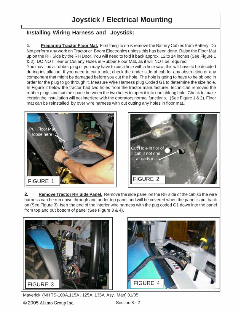
© 2005 Alamo Group Inc. Section 8 - 2
Maverick (NH TS-100A,115A , 125A, 135A Asy. Man) 01/05
Installing Wiring Harness and Joystick:
1. Preparing Tractor Floor Mat. First thing to do is remove the Battery Cables from Battery, DoNot perform any work on Tractor or Boom Electronics unless this has been done. Raise the Floor Matup on the RH Side by the RH Door, You will need to fold it back approx. 12 to 14 inches (See Figure 1& 2). DO NOT Tear or Cut any Holes in Rubber Floor Mat, as it will NOT be required.You may find a rubber plug or you may have to cut a hole with a hole saw, this will have to be decidedduring installation. If you need to cut a hole, check the under side of cab for any obstruction or anycomponent that might be damaged before you cut the hole. The hole is going to have to be oblong inorder for the plug to go through it. Measure Wire Harness plug Coded G1 to determine the size hole.In Figure 2 below the tractor had two holes from the tractor manufacturer, technician removed therubber plugs and cut the space between the two holes to open it into one oblong hole. Check to makecertain the installation will not interfere with the operators normal functions. (See Figure 1 & 2). Floormat can be reinstalled by over wire harness with out cutting any holes in floor mat..
FIGURE 1
Pull Floor Matloose here
Joystick / Electrical Mounting
FIGURE 2
Cut Hole in flor ofcab if not onealready in it.
2. Remove Tractor RH Side Panel. Remove the side panel on the RH side of the cab so the wireharness can be run down through and under top panel and will be covered when the panel is put backon (See Figure 3). Isert the end of the interior wire harness with the pug coded G1 down into the panelfrom top and out bottom of panel (See Figure 3 & 4).
FIGURE 3 FIGURE 4

© 2005 Alamo Group Inc. Section 8 - 3
Maverick (NH TS-100A,115A, 125A, 135A Asy. Man) 01/05
Arm Rest WeldmentP/N 02981415
FIGURE 5
Installing Seat Replacement ArmRest:1. Replace RH Factory Arm Rest. The fac-tory seat RH arm rest will be replaced with aweldment designed to serve as the armrest andmount for the emergency stop switch and thejoystick assembly (See Figure 5, 6 & 7). Unbolt thefactory arm rest and bolt on the replacement armrest. The Arem rest is retained using the same typemethod as thr factory arm rest, this is what allowsthe arm rest to be raised up and down (See Figure6) See the bottom of the welded replacement armrest. It may be required to use a die grinder in slottedhole th help with alignment of retaining bolt. (SeeFigure 6).2. Install Emergency Stop Switch. The emer-gency Stop (E-Stop) Switch mounts into the armrest in the smaller of the two holes. The Knob andmounting nut will need to be removed and theswitch installed from the bottom of the arm rest.Replace mounting nut and knob (See Figure 5 , 7 &8)3. Locate Joystick Assembly. The joystickassembly has a flange around the bottom, it uses 4screws to mount joystick to the arm rest. Lower thewiring of joystick down through hole in arm rest.Make certain the three plugs are in the hole and notbeing pinched. (See Figure 9 & 12).
Locating Joystick and electrical components:
1. Joystick Assembly with Resister Harness. The joystick has the resister wire harnessattached to it when you received the joystick.2. Emergency Stop Switch. The emergency Stop (E-Stop) Switch will be sent with the knob andmounting nuts installed onto it. These will need to be removed when mounting switch.3. Replacement Seat Arm Rest. The Tractor seats Rh arm rest will be replaced with a fabricatedone to mount E-Stop Switch and Joystick.4. Wire Harness. The Wire harness is in two piece, The interior harness inside the cab and theexterior harness connecting to the interior harness and running outside the cab to the pump and tankarea at the front of the tractor.5. Wire Harness through Floor of Tractor Cab. Some tractors may have a hole all ready throughthe floor of the cab on the RH side. Lift Floor mat and check, if no hole (possible with rubber plug in it)a hole will need to be cut with a hole saw. If cutting holes in floor of cab always check under side of floorto make certain there are no components that will be hit and damaged by saw. DO NOT use a torch tocut holes in cab floor.6. Access Panels of Tractor interior. Panels in the cab will need to be loosened and/or removedto gain access to connections and/or mounting of components. Do not remove any panels untilinstructed to do so.
Joystick / Electrical Mounting
FIGURE 6
Under Side ofWelded Arm
Rest withSlotted Hole

© 2005 Alamo Group Inc. Section 8 - 4
Maverick (NH TS-100A,115A , 125A, 135A Asy. Man) 01/05
Joystick / Electrical Mounting
1234
Z AXIS
1234
Y AXIS
1234
X AXIS
P4-2
P4-1
P2-3
P2-2P2-1
P3-3
P3-2 P3-1
H7
H6
H9
H10
H11
H12
H1(+)
H2(-)
H3(T
2)H
4(T3)
H5(T
4)H
6(T5)
9 7 8 6
5
4 3
21
Wire Harness Side
P4 P2 P3
Joystick Side
Red
Blk/W
htBlu
Red/W
htB
rn/Blk
Vio
Blk/R
ed
P4-3
Yel/Red
Blk
Red
BluB
lk/Wht
Red/W
htVioB
rn/Blk
Yel/Red
Blk/R
ed
Blk
PCB Assembly
Pin Numbers &Locations
Pin Numbers &Locations
Resistor HarnessP/N 02981990 Isattached to theJoystick when it is recieved.
J17 8 9
4 5 6
1 2 3
FIGURE 7
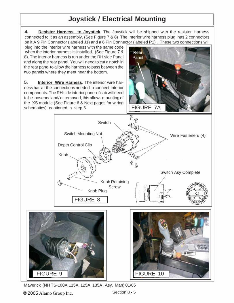
© 2005 Alamo Group Inc. Section 8 - 5
Maverick (NH TS-100A,115A, 125A, 135A Asy. Man) 01/05
FIGURE 9
when the interior harness is installed. (See Figure 7 &8). The Interior harness is run under the RH side Paneland along the rear panel. You will need to cut a notch inthe rear panel to allow the harness to pass between thetwo panels where they meet near the bottom.
5. Interior Wire Harness. The interior wire har-ness has all the connections needed to connect interiorcomponents. The RH side interior panel of cab will needto be loosened and/ or removed, this allows mounting ofthe XS module (See Figure 6 & Next pages for wiringschematics) continued in step 6 FIGURE 7A
Joystick / Electrical Mounting
Knob Plug
Knob RetainingScrew
Knob
Depth Control Clip
Switch Mounting Nut
Switch
Wire Fasteners (4)
Switch Asy Complete
FIGURE 8
4. Resister Harness to Joystick. The Joystick will be shipped with the resister Harnessconnected to it as an assembly. (See Figure 7 & 8) The Interior wire harness plug has 2 connectorson it A 9 Pin Connector (labeled J1) and a 6 Pin Connector (labeled P1) . These two connections willplug into the interior wire harness with the same code
RearPanel
FIGURE 10

© 2005 Alamo Group Inc. Section 8 - 6
Maverick (NH TS-100A,115A , 125A, 135A Asy. Man) 01/05
7. XS Module P/N 02981533. The XS module(See Figure 13) mounts in side the tractor cabbehind the right hand side panel (See Figure 13 &14). The Connections (Three Separate Pugs, Can 1,Can 2 & D) will be inside the side panel after it isreinstalled and will not be visible unless you removethe side panel (See Figure 14 , 16, 17 & 18 ). The XSModule does not have a mount bracket, it will need tobe mounted by the assembly technician insidepanel where it will be out of the way, not interfere withany tractor components and be secured. It can betied in or bolted. The Only Plugs protruding frombehind RH Interior panel shoud be the plugs for thedisplay control box (See Figure 14, 16, 17 & 18). FIGURE 13
XS ModuleP/N 02981533
FIGURE 11
Joystick / Electrical Mounting
1
2
3
4
56
7
8
9
P-1
P2
P3
P4PCB
To Activate Trigger Push In
Joystick P/N 02981347with Resister Harness
J1
FIGURE 12
appropriate place to connect with the interior components.The harness to the joys stick will need to be run along thepanel at the back of the cab. CAUTION: The Harness hastwo wires that run under the floor mat, the positivewire MUST connect to the ignition key switch of thetractor for a power source. DO NOT Connect thepositive wire anywhere else (See Step 9 & Figure 14wire CC1).. The plug (G1) will need to run through the floorto the exterior of the cab, it will connect to the plug (G2) ofthe exterior harness. (See figure 11, 12, 13 & 14). Securewires under arm rest.
6. Interior Wire Harness (continued). The interior wire harness schematic (See Figure 11 & 12)shows the wire harness as it is run through the cab. The XS Module will need to be mounted inside thecab, the best place is behind the RH side panel (See Figure 6, 9 & 12). The wire harness will need it beput under this panel, also with the connectors in the

© 2005 Alamo Group Inc. Section 8 - 7
Maverick (NH TS-100A,115A, 125A, 135A Asy. Man) 01/05
Interior Wire Harness Schematic P/N 02981375B
G1 (Connects to G2 Plugof Exterior Wire Harness)
CC1 +Pos.Key SwitchConnection
CC2 - Neg.ChasisGround
X1 ( ControlBox DisplayConnection
K3 ( ControlBox DisplayConnection
D ( XS ModuleConnector)
Can 1 ( XSModule
Connector)
Can 2 ( XSModule
Connector)
J1 Joystick Connection (9 Pin)
P1 Joystick Connection (6 Pin)
Remove console cover, tie strapXS Module P/N 02981533 inside
console
Code Connection
Can 1 XS Module Can1 Connection (2 of 3 Connections)Can 2 XS Module Can 2 Connection (3 of 3 Connections)CC1 + Positive Key Switch Connection (MUST Connect to key switch wire)CC2 - Negative Chasis GroundD XS Moudule C1 Connection (1 of 3 Connections)G1 Exterior Harness G2 Plug (coonnects Interior & exterior Harness)J1 Joystick Resister Harness (9 Pin Plug)K3 Control Box Display Connection (1 of 2 Connections)M1 E-Stop Switch (use A or B of Switch)M2 E-Stop Switch (use A or B of Switch)X1 Control Box Display Connection (2 of 2 Connections
FIGURE 14

© 2005 Alamo Group Inc. Section 8 - 8
Maverick (NH TS-100A,115A , 125A, 135A Asy. Man) 01/05
Joystick / Electrical Mounting
FIGURE 16
K3
X1
Display ControlBox Connections
8. Wire Exterior & Interior Harness Schematic. The wire harness schematics and instructionswill need to be used together to install the wire harness. The interior Harness and the exterior harnesswill connect together with one plug connection. Figure 14, 16,17, 18 & 19) pertain to the interior harness,Plugs have codes on them to identify where they connect, the connections will have codes on them toidentify where the connection goes. The code on the plug and the code on the connection may not be thesame, see the code connection listings in the illustrations to identify the connection location.
FIGURE 18
FIGURE 17
Display ControlBox Connections
Cut Notch in Small cover panel toallow harness to fit through
Can1Can2 C1
XS ModuleP/N 02981533
FIGURE 15
9. Plugs for Display Control Box. The wire plugs forthe display control box will come up through the smallcover on top of the right hand side panel (See Figure 16,17, 18 & 19). When the small cover is replaced the plugsand wires need to be moved to the back of the panel nearthe RH rear cab post (See Figure 17 & 18). Cut a notch inthe panel at the rear so the cover will fit down around thewire harness plugs (See Figure 17 & 18). Also the reartractor panel will need a notch cut in it to allow the wireharness to be installed between the side and rear panel.Cut this notch near the bottom of the rear panel (SeeFigure 19)
FIGURE 19
RearPanel
Wire Harness to Joystick

© 2005 Alamo Group Inc. Section 8 - 9
Maverick (NH TS-100A,115A, 125A, 135A Asy. Man) 01/05
Interior Wire Harness Schematic P/N 02981375B
CAN 2XS MODULE
CAN 1 XSMODULE
K3
X1
G1
CC2
CC1 (Mustconnect toKey switch
wire)
P1
J2
M1M2
D
FIGURE 20
NOTE: See Figure 11 forlisting of Code Locations

© 2005 Alamo Group Inc. Section 8 - 10
Maverick (NH TS-100A,115A , 125A, 135A Asy. Man) 01/05
Interior XS Module & Display Control Box
10. Tractor RH Side Panel reinstalled. When thetractor side panel is reinstalled the plugs (2 Plugs K3 &X1) for the Display control box will be sticking up out frombe hind the panel (See Figure 21), Run the wiring harnessin from behind panel, use caution to not let wire harnessinterfere with or be in a position to damage or be damagedby other tractor components behind panel.
11. Install Display Control Box Mount Bracket. Thedisplay mount control box mount to the Rh rear cab post(See Figure 22 & 23) . There are two plastic plugs in theplastic cover over cab post. Remove these two plug toexpose two 10 mm bolt holes in cab post. Position themounting bracket with the bent end at the post and usingthe 10 mm bolts furnished bolt the bracket to the post.
12. Install Display Control Box. The display controlbox will bolt to the mount plate P/N 02982324 that ismounted to the RH Rear Cab corner post (See Figure 22,23 & 24). There is a wire setion on disply control box thatwill pug into the two plugs on the interior harness plug KS& X1 (See Figure 21 & 22)The display control box cannot be tested until the interiorand exterior wiring harness installation has been com-pleted and all the other installations of unit have beendone. DO NOT reconnect battery cables at this time, theelectrical wiring is NOT done.
Bend Upward 60° Here
P/N 02982324 MountPlate - (Iqan) DisplayControl Box Mount
FIGURE 23
9. Connect Wires to Key Switch. There are two wires on the interior Harness that connects to thekey switch (Wires CC1 and CC2) these need to be routed under floor mat and in behind dash panels.CAUTION:The positeve wire (CCI) MUST be connected to the wire from the key ignition switchof tractor for an electrical power supply. DO NOT connect the power supply wire (CC1) to anyother power supply as it could cause interference with the electronic components due to apower surge
FIGURE 24
DisplayControl Box
Cab RH RearCorner Post
FIGURE 22
P/N 02982324 MountPlate - (Iqan) DisplayControl Box Mount
FIGURE 21
Display ControlBox Connections
K3
X1

© 2005 Alamo Group Inc. Section 8 - 11
Maverick (NH TS-100A,115A, 125A, 135A Asy. Man) 01/05
Exterior Wire Harness Schematic P/N 02981375A
Plug Valve ValveLabel Function LabelAA1 Swivel BAA2 Swivel AAA3 Tilt AAA4 Tilt BAA5 Telescope AAA6 Telescope BAA7 Dipper AAA8 Dipper BAA9 Lift AAA10 Lift BAA11 Swing / Door AAA12 Swing / Door B
X1 & X2(Return Filter)
E (XT2 Module)
S1 (Temp Sensor)
R1 (Cooler Fan)
G2 (Plug to InteriorWire Harness)
Y1 Connect to White Wire & Y2 Connectto Black Wire ( Valve Filter)
W1 (Charge Filter)
F (XP2 Module)
H1 & H2 ( Lock Valve Connection)
AA (See Below)
BB (Diverter Valve)
FIGURE 25
13. Exterior Wire Harness. The exterior wire harness will run from the cab of the tractor to the front.It will include the wiring for the sensors at the pump. The connections for the valve actuator assemblies.The electronic modules that are mounted to the right side of the tank and the module on the front of thevalve. The plugs have codes labeled on them, there is a matching code on them where the plugs areconnected. Some plugs have instructions and/or color codes. Read the next pages of this manual tobecome familiar with the wire harness connections. There are two electronic modules bolt on the tankassembly in the front of the tractor. The XT2 module bolted on the right hand side of the tank and the XP2bolt on the LH side in front of the 6 spool valve. (See Figure 25, 27 & 28). The exterior wiring harness shouldbe laid out and connections need to be start at the first connection coming from the tractor cab connection,this allows the harness to be moved around and under components as needed.NOTE; V1 Pump Solenoid 2 is only used when the Timbercat Head is installed and will be installed intoplug next to Pump solenoid 1 which is used with all heads. Note: Unless the timbercat head is used onlySolenid 1 will be installed which is Plug V1, leave plug T1 tie to othrer plug out of the way.
NOTE; Decal, Stripes to Base and Solid to Rod end refers to the plastic ties on hoses only ¬ electricl connections
Decal Below shows the Hose location and Plastic tie color on hose.Also the markings for the wire harness plugs on valve ("A" or "B")See Figure 18 & 18A)
FIGURE 26
Pump SolenoidT1 (Sol 2) & V1(Sol1)

© 2005 Alamo Group Inc. Section 8 - 12
Maverick (NH TS-100A,115A , 125A, 135A Asy. Man) 01/05
T1
BB
AA12AA11
AA10AA9
AA8AA7
AA6AA5
AA4AA3
AA2
AA1
Z1
V1
Y2
Y1
H1
H2
F
X2X1
R1
S1
G2
W1E
AA1 Swivel Cylinder, CCWAA2 Swivel Cylinder, CWAA3 Tilt Cylinder, DownAA4 Tilt Cylinder, UpAA5 Telescope Cyl, INAA6 Telescope Cylinder, OutAA7 Dipper Cylinder, DownAA8 Dipper Cylinder, UpAA9 Lift Cylinder, DownAA10 Lift Cylinder, UpAA11 Swing / DoorAA12 Swing / DoorBB Solenoid Valve Connection for Diverter ValveE Connector XT2 ModuleF Connector XP2 ModuleG2 Exterior Harness to G1 Interior HarnessH1 Lock Valve ConnectionH2 Lock Valve ConnectionR1 Cooler Fan ConnectionS1 Temperature Connection SensorT1 Pump Solenoid 1 ConnectionV1 Pump Solenoid 2 (Only on Timbercat Head)W1 Charge Filter connectionX1 Return Filter ConnectionY1 Common, Connect to White Wire at FilterY2 Signal, Connect to Black Wire at FilterZ1 Negative Chasis Ground
Connection Markings on Exterior Wire Harness:
Exterior Wire Harness Schematic P/N 02981375A
FIGURE 27

© 2005 Alamo Group Inc. Section 8 - 13
Maverick (NH TS-100A,115A, 125A, 135A Asy. Man) 01/05
14. Diverter Valve Wiring Connection: The plug for the diverter valve is at the end of the exteriorwiring harness and will be marked with code BB. The plug and wire will run down the LH side of tractorfrom the front mounted hydraulic pump / Tank. The diverter valve is bolted the the LH front FrameMount bracket. The holes are already in the bracket and the diverter valve should have already beenmounted. If valve has not been mounted it can be mounted now (See Figure 27, 28 , 31 & 38).
Exterior Wire Harness Schematic P/N 02981375A
PressureSupplyPort "P"
ReturnTo Tank
"T"
"B"
"A""A""A""A""A""A"
"B""B""B""B""B"
Sw
ing
Lift
Tele
scop
e
Hea
d Ti
lt
Hea
d Sw
ivel
/ D
oor
(To
Div
erte
r Va
lve)
Dip
per
G
G/W
OR R/W
Y/WB/WOR/W
Y
R
B
G/W
G
Six Spool Control Valve
FIGURE 28
External Wire Connec-tions for valve are marked"A" and "B" on Valve &AA1 thru AA12 on wireharness connections
A A11
A A12
B
A
A A9
A A10
B
A
A A7
A A8
B
A
A A5
A A6
B
A
A A3
A A4
B
A
A A2
A A1
B
A
XT2 (Expansion, Transmission)
FIGURE 30 Bolts on RH side on side of Tank
XP2 (Expansion, Power)
Bolts on LH side in front of Valve
FIGURE 29

© 2005 Alamo Group Inc. Section 8 - 14
Maverick (NH TS-100A,115A , 125A, 135A Asy. Man) 01/05
Exterior Wire Harness Schematic P/N 02981375A
VS . 125/F
C2
C3SA
E 4
P1P2
Valve "B" Port toDiverter valve P1 Port
(G/W Tie)
Valve "A" Port toDiverter valve P2 Port
(G Tie)
4 Through holes aremounting holes
Diverter Valve "C1" Portto Swivel Cyl BaseEnd Port (G/W Tie)
Diverter Valve "C4" Portto Swivel Cyl Rod End
Port (G Tie)
Diverter Valve "C2" Portto Door Cyl Base End
Port (Y/W Tie)
Diverter Valve "C3" Portto Door Cyl Rod End
Port (Y Tie)
Diverter Valve
FIGURE 31
Diverter Valve Wire Harness Connection BB ofexterior harness connects here
FIGURE 32
Connecting Oil CoolerAnd Fan Assembly to Ex-terior Wire Harness15. Oil Cooler / Fan As-sembly. The Oil cooler / fanassembly is for cooling the oilbeing returned from the MotorCase Drain. The fan is con-nected to the control box andis turned on & off automati-cally. It set to run on a programthat will run the fan in the cool-ing rotation for a designatedtime, then stop, reverse therotation (cycle to clean debrisoff of cooler, then stop andreverse the fan again and be-gin the cycle all over again.
The connection to thecooler on the exterior wire har-ness is marked with code R1.The connection from the fanwill have two wires, a Blue (+connection) and a black (- con-nection) (See Figure 32).
Exterior wireharness connec-tion marked R1connects here

© 2005 Alamo Group Inc. Section 8 - 15
Maverick (NH TS-100A,115A, 125A, 135A Asy. Man) 01/05
Maverick Sensor Connections:
1. Instrumentation The Maverick Boom utilizesinstrumentation for certain decision making activi-ties. Listed below are the sensors included on thisunit. Tank Temperature Sensor, Charge PressureFilter Switch, Valve Pressure Filter Switch and Re-turn Filter Switch.
2. Tank Temperature Sensor. The tank tem-perature sensor monitors the fluid temperature inthe area of the pump suction screens. the tempera-ture is real time and is used on the network toaccomplish certain objectives. The first, is to displayon the interface while the cutter circuit is operating.The second, is to be used to control the electric fanon the hydraulic cooler. At any time the fluid levelreaches 150° F. the fan is activated and remainsactivated until fluid temperature drops to or belowthe desired temperature (See Figure 33).
3. The Charge Pressure Filter Switch Thecharge filter pressure switch has three wire comingout of it, a white , black and Blue wire. The Blue wirewill not be used and will be cut off. The chargepressure filter switch is located at the filter in thecharge loop on the hydrostatic pump (See Figure34). The sensor monitors the back pressure createdby the filter element when in use. When the backpressure reaches a setting of 50 psi the switch willtrigger and prompt the operator for a filter elementchange of filter element.
4. The Valve Pressure Filter Switch The Valvepressure filter switch is located at the pressure filterin the valve pressure circuit, between the closedcenter load sense pump and the control valve (SeeFigure 35). The sensor monitors the back pressurecreated by the filter element when in use. When theback pressure reaches a setting of 50 psi the switchwill trigger and prompt the operator for a filterelement change.
WARNING! This filter does not have a by-pass. The element must be changed at the appropri-ate time to avoid element damage and systemcontamination.
FIGURE 33
FIGURE 34
FIGURE 35
Exterior Wire Harness Schematic P/N 02981375A

© 2005 Alamo Group Inc. Section 8 - 16
Maverick (NH TS-100A,115A , 125A, 135A Asy. Man) 01/05
5. The Return Filter Switch. The return filterswitch is located at the return filter mounted on to thetank top. The fluid returning from the cylinder controlvalve is filtered before returning to tank at this loca-tion (See Figure 36). The sensor monitors backpressure created by the filter assembly while cylin-der circuit is in operation. When the back pressurereaches 25 psi the switch will trigger and prompt theoperator for a filter element change.
WARNING! This filter does not have a by-pass. The element must be changed at the appropri-ate time to avoid element damage and systemcontamination.
6. Oil Cooler & Fan Assembly. The oil cooler /fan assembly bolts to the tank rail mount bracketbetween tractor front axle and hydraulic tank. Themounting holes are in the tank rail mounting brack-ets (See Figure 37). There will be two hose con-nected to the cooler, one from the motod case drainto the cooler and one from the cooler to the tankreturn, These hose will have blue plastic ties onthem.
FIGURE 36
Exterior Wire Harness Schematic P/N 02981375A
FIGURE 37
FIGURE 38
Diverter Valve
Diverter Valve Plug

© 2005 Alamo Group Inc. Section 8 - 17
Maverick (NH TS-100A,115A, 125A, 135A Asy. Man) 01/05
Decal Mounting
Installing Warning andInstruction Decals:
1. Always clean windows before installingdecals. Windows must be dry and free of any oil,after cleaning do not touch windows before decalsare installed. Take precaution to make sure decalsare right side up and straight when installing them,they cannot be taken off and redone.2. Identify Decals. Lay all the Decals out and IDeach one so you will know which is installed where.The Decals will have the Part Number on them in thelower corners. Decal No. Description 00763977 Notice to Owner 02964677 Important - Boom Rest 02963524 Attention - Boom Swing 02965093 Proper Engine Operating 02965262 Warning - Hose Burst 02967827 Multi - Hazard
3. Multi-Hazard - Danger Decal. This is in-stalled on the Left Side Window of Cab on the insideto Drivers Left. P/N 02967827 (See Figure 39)
4. Warning Hose Burst Decal. This installs onthe Right Side Window of Cab on the Inside toDrivers Right P/N 02965262 . (See Figure 40)
5. Notice To Owner Decal. This installs on theinside top rear of Right Door Glass P/N 02964677 (SeeFigure 41)
6. Attention Boom Swing Decal. This installs on theinside top rear of Right Door Glass P/N 02963524 (SeeFigure 41)
7. Important Boom Rest Decal. This installs on theinside top rear of Right Door Glass P/N 02964677 (SeeFigure 41)
8. Proper Engine Operating Decal. This installs onthe inside top rear of Right Door Glass P/N 02965093 (SeeFigure 41)
FIGURE 3902967827
FIGURE 4002965262
FIGURE 41
0076397702963524
02964677 02965093

© 2005 Alamo Group Inc. Section 8 - 18
Maverick (NH TS-100A,115A , 125A, 135A Asy. Man) 01/05
NOTES

© 2005 Alamo Group Inc. Section 9 - 1
Maverick (NH TS-100A,115A, 125A, 135A Asy. Man) 01/05
MAVERICKNew Holland Tractor
TS-100A,115A, 125A, 135A
Boom & HeadInstallation
Section 9

© 2005 Alamo Group Inc. Section 9 - 2
Maverick (NH TS-100A,115A, 125A, 135A Asy. Man) 01/05
Boom / Head Installation
Figure 1
Swing Cyl. Hosewith Green /White Tie
Swing Cyl. Hosewith Green Tie
Rear of Tractor
Boom Installation / Boom Hoses:1. Turret Assembly, The turret assembly hasthe cylinders connected and the hoses are con-nected to the cylinders. The end of the hoses willbe sticking up through the turret mount weldmentbetween turret and tractor. The hoses will needto be connected there and routed to the hydrauliccontrol valve. One hose will have a Green Tieand one a green and white tie where the come upthrought the turret mount weldment. (See Figure3).
2. Booms Are recieved from the factory withthe Sections of Boom Assmebled to together.The Boom Sections are assembled with the hy-draulic lines and cylinder connected. The hosewill be connected to the boom that are routed tothe control valve and diverter valve and bundledtogether. (See Figure 4). The Boom Hoses areprotruding out the turret mount end of the boom.The Hose connections on the head end will beshipped with metal caps on them, these are toprotect the lines from contamination and shouldnot be removed until the hoses are being in-stalled (See Figure 5). The hose that attaches tothe boom are sent installed on the head assem-bly and the hose will also have plugs in them.
3. Boom Lift Cylinder. The boom lift cylinderwill be connected to the boom at the rod end ofthe cylinder (See Figure 2 & 4) when it is shippedfrom factory. The hoses will also be connected tothe cylinder. The retaining pin for the lift cylinderwill be located in the turret assembly. The LiftCylinder will be fastened to boom with tie wire. Itwill not be required to remove this tie wire beforemounting boom on turret assembly. -
4. Booms & Lift Cylinder Mounting Pins.The Boom and lift cylinder mounting pins areshipped installed in the turrert assembly. Re-move both pins in preparation to mounting theboom. (See Figure 3)
Figure 3
Main BoomMount Pin
Lift Cyl. BaseEnd Mount Pin
Figure 2
LiftingPoint

© 2005 Alamo Group Inc. Section 9 - 3
Maverick (NH TS-100A,115A, 125A, 135A Asy. Man) 01/05
5. Lower Boom onto Turret Assembly. Us-ing an over head hoist lift the boom by placing alift strap at the boom hinge point (See Figure2), the boom assembly will be shipped with thetwo boom end tie wired together (See Figure3A). The wire tie will need to be removed as itis tied through the boom hinge pin hole. Lift theboom above the turret assembly and lower itback down onto the turret assembly aligningthe boom with the mounting pin hole. Install theMount Pin through the turret and into theboom. Make certain the pin is installed cor-rectly as one side of the pin is self locking indesign. Tighten the pin retaining nut and installcotter pin. (See Figure 3C)
6. Connect lower end of Lift Cylinder. TheBase end (lower end) of lift cylinder will mountinto the turret under the boom mount. The Cyl-inder will have to be extended to connect, Ifcylinder has to be extended the best way is tounplug the ends of the lift cylinder hoses wherethey come out of the boom, these will be the #6 hose with the Orange Tie and the # 6 hosewith the orange / White Tie. When pulling (ex-tending or collapsing cylinder) always put theopened end of the hoses into a clean drain panas oil will run out of the cylinder when extendedor collapsed. After installing the cylinder lowermounting pin re-plug the hoses that were in thedrain pan until ready to connect hoses.
7. Connect Head to Boom. The mountingpins to install the head onto the boom will beshipped installed in the mount weldment. Re-move the mounting pins. Use the hoist to lowerboom down over head to connect head, Alignthe upper head mount pin. The lower mountpin is the connect the lift link. (See Figure 4 &5). The Door Cylinder and the Swivel Cylinderare shipped installed on the head with thehoses connected to the cylinder.
Boom / Head Installation
Figure 3A
Turret EndOf Boom
Boom MountingPin Hole
Figure 3B
Mount Pin
Lift Cylinder
Figure 3C

© 2005 Alamo Group Inc. Section 9 - 4
Maverick (NH TS-100A,115A, 125A, 135A Asy. Man) 01/05
Figure 5
8. Heads Are received from the Factory withthe Cylinder and Head hoses Attached to Head.The head will be received with the door cylinder,swivel cylinder and Motor attached to the head.The Hoses for the cylinders and the motor willconnect to the boom. There is a decal that isinstalled on the side of the boom that showswhere the hoses connect to the fitting that havethe metal caps on them. The fittings for the headare located on the side of the main Boom. Thehoses must be connected in the correct order tomake certain of correct operation (See Figure 4,5, 6, 7, 8, 9 & 10).
9. Two Head Options. There are two headsavailable, 60" (See Figure 4,5 & 6) which has thehead Swivel attachment on it. The 50" Head whichwill not have the swivel attachement (See Figure 9& 10) If using the 50" head leave the ports forswivel cylinder on boom capped (See Figure 8)
10. Connect Hose From Boom to ControlValve. The cylinder hoses will connect to thecontrol valve mounted on the front of the tractorwith the exception of the Door and Swivel Cylinderhoses they will connect to the diverter valve andthen there are two hoses that connect tothediverterr valve to the 6 spool control valve (SeeFigure 11). The hoses for door and swivel will berouted under the tractor along the center underframe weldment to the diverted valve which will bemounted on the LH side of the tractor on the frontframe mount bracket.
Figure 4
Figure 6
Figure 7
60 Inch Head withSwivel Hitch Mount
60 Inch Head withSwivel Hitch Mount
60 Inch Head withSwivel Hitch Mount
Boom / Head Installation

© 2005 Alamo Group Inc. Section 9 - 5
Maverick (NH TS-100A,115A, 125A, 135A Asy. Man) 01/05
Figure 8
SwivelCyl. # 4 Hose
(Green / White Tie)
SwivelCyl. # 4 Hose (Green Tie)
DoorCyl. # 4 Hose(Yellow Tie)
Motor Pressure# 16 Hose(Red Tie)
Motor Tank Return#16 Hose
(Orange Tie)Motor Case Drain
#12 Hose (Blue Tie)
DoorCyl. # 4 Hose
(Yellow / White Tie)
Boom / Head Installation
Head MountPin Hole
Head Lift LinkPin Hole
Figure 9
Figure 10
50 Inch Head w/oSwivel Hitch Mount
50 Inch Head w/oSwivel Hitch Mount

© 2005 Alamo Group Inc. Section 9 - 6
Maverick (NH TS-100A,115A, 125A, 135A Asy. Man) 01/05
Boom / Valve Hydraulic Schematic
11
11
11
1212
1212
11
Swin
g
Boo
m L
ift
Dip
per
Tele
scop
e
Hea
d Ti
lt
Swiv
el /
Doo
r
Pressure Supply(Red Tie)
Tank Return(Orange Tie)
"A" Ports
"B" Ports
Gre
en /
Whi
te T
ie
Gre
en T
ie
Boom Lift Cyl
# 6 Hose
Orange / White Tie
Orang
e Tie
Dipper Cyl# 6 Hose
Blue TieBlue / White Tie
Telescope Cyl# 6 Hose
Yellow / White Tie
Yellow Tie
Head Tilt Cyl
Red TieRed / White Tie
P1
P2
C1C2
C3 C4Sw
ivel
Cyl
# 4
Hos
e
# 4
Hos
e
Doo
r Cyl
Gre
en /
Whi
te T
ie
Gre
en T
ie
Yello
w /
Whi
te T
ie
Yello
w T
ie
Gre
en /
Whi
te T
ieG
reen
Tie
Diverter Valve
6 Spool Control Valve
# 6 HoseSwing Cyl
No Colored Ties only HoseBands P/N 02981825
Figure 11
# 6 HoseSwing Cyl
Stabilizer Cyl# 4 Hose
Returns to same port ontan as Oil cooler Hose
Tees into Lift ("B" Port) Hose (No Plastic Tie)

© 2005 Alamo Group Inc. Section 9 - 7
Maverick (NH TS-100A,115A, 125A, 135A Asy. Man) 01/05
Boom / Head Installation
The other cylinder hoses from the boom willbe inserted into sleeving material and also be routedunder the tractor to the LH side (See Figure 14). Theywill continue up the LH side to the front of the tractorwhere they will connect to the valves ports. Thehoses will be held to the frame with metal hose hold-ers bolted to the tractor frame (See Figure 15).
NOTE: the hoses must be run through thesleeving material. On the LH side there is a hole in thecenter frame weldment the hoses can be run throughit if wanted. Connect the hoses to the valve as shown(See Figure 11 & 17) Figure 12
Figure 13 Figure 14
Figure 15
11. Routing Cylinder Hoses from Boom to Valve The Hose from the boom to the valve will besplit, the four hoses to the door cylinder and swivel cylinder will run together through a section ofsleeving material to the RH side of the tractor (See Figure 12). On the Right hand side of thetractor the four hoses will connect to the diverter valve in the coded locations (See Figure 11). Tiethe hoses to the frame under the tractor (See Figure 13). The two hoses from the diverter valve willcontinue along the LH side of tractor with sleeving material over them (See Figure 13) to the frontof the tractor. They will have hose support brackets on them that bolt to the side of the tractor (SeeFigure 13) where they will be connected to the valve at the Door / Swivel Ports in the correct order(See Figure 16 & 17).
Figure 16
Sleeving Materialfor Hoses
Hose SupportBracket

© 2005 Alamo Group Inc. Section 9 - 8
Maverick (NH TS-100A,115A, 125A, 135A Asy. Man) 01/05
HYDRAULIC HOSE CODES AT VALVEHydraulic Hose Band Mark Color Codes: Hose's and/or fittings are marked with a
Color Coded Plastic Band around it. Some Bands are a solid Color and some are Colored with aStripe. The purpose of the colored bands are to provide a quick reference for hose and portconnection. A metal band is also attached to the hose, on that band is an Alamo Industrial PartNumber for reference if needing a replacement hose. Always Check Hose Size, Color Code& Part Number (See Figure 4)Boom Cylinder Circuit Hoses:Color Tie (Code) Hose Size Port Diverter Hyd. FunctionGreen G SAE # 6 A --- Swing, Back (Rod End)Green / White G/W SAE # 6 B --- Swing, Forward (Base End)Orange OR SAE # 6 A --- Lift, Down (Rod End)Orange / White OR/W SAE # 6 B --- Lift, Up (Base End)Blue B SAE # 6 A --- Dipper, In (Rod End)Blue / White B/W SAE # 6 B --- Dipper, Out (Base End)Yellow Y SAE # 6 A --- Telescope, In (Rod End)Yellow / White Y/W SAE # 6 B --- Telescope, Out (Base End)Red R SAE # 6 B --- Head Tilt, Up (Rod End)Red / White R/W SAE # 6 A --- Head Tilt, Down (Base End)Green G SAE # 4 A P2 Control Valve tor Diverter valveGreen / White G/W SAE #4 B P1 Control Valve to Diverter ValveGreen G SAE # 4 --- C4 Swivel, CW (Rod End)Green / White G/W SAE # 4 --- C1 Swivel, CCW (Base End)Yellow Y SAE # 4 --- C3 Door, Open (Rod End)Yellow / White Y/W SAE # 4 -- C2 Door, Closed (Base End)Orange OR SAE#12 T --- Valve Return To TankRed R SAE#12 P -- Pressure to Valve.
Motor Circuit Hoses to Boom Connections: (Listed as reference)Color Tie (Code) Hose Size Hyd. FunctionRed R SAE # 16 -- Pressure Flow to MotorOrange OR SAE # 16 -- Return Flow From MotorBlue B SAE # 8 -- Case Flow From Motor to BoomBlue B SAE # 12 -- Case Flow at Boom to Tank
Hydraulic Hose Connections
Diverter Valve.:The Diverter Valve bolts onto the front frame mount bracket on the LH side of the tractor, the holes
are in the bracket (See Figure 5 & 6). The Diverter valve is a electrical operated valve that allows thehydraulic pressure to be shared to operate two (or more if valves are stacked) functions with a singlepressure supply. This valve is strictly a diverter valve and is designed to direct the pressure, not regulatethe flow or pressure.
The Port openings on this diverter valve are marked with letter number codes which show whichport is connected to which hose and where that hose connect on other end (See Figure 4, 5 & 6))Port Function & ConnectionP1 Hose Hydraulic Pressure from Door / Swivel (B) Port on Control Valve (G/W Tie)P2 Hose Hydraulic Return to Door / Swivel (A) Port on Control Valve (G Tie)C1 Hose to Head Swivel Cylinder Base End (G/W Tie)C2 Hose to Door Cylinder Base End (Y/W Tie)C3 Hose to Door Cylinder Rod End (Y Tie)C4 Hose to Head Swivel Cylinder Rod End (G Tie)

© 2005 Alamo Group Inc. Section 9 - 9
Maverick (NH TS-100A,115A, 125A, 135A Asy. Man) 01/05
Hydraulic Hose Connections
VS . 125/F
C2
C3SA
E 4
P1P2
Valve "B" Port toDiverter valve P1 Port
(G/W Tie)
Valve "A" Port toDiverter valve P2 Port
(G Tie)
4 Through holes aremounting holes
Diverter Valve "C1" Portto Swivel Cyl BaseEnd Port (G/W Tie)
Diverter Valve "C4" Portto Swivel Cyl Rod End
Port (G Tie)
Diverter Valve "C2" Portto Door Cyl Base End
Port (Y/W Tie)
Diverter Valve "C3" Portto Door Cyl Rod End
Port (Y Tie)
Diverter Valve
FIGURE 17
PressureSupplyPort "P"
ReturnTo Tank
"T"
"B"
"A""A""A""A""A""A"
"B""B""B""B""B"
Sw
ing
Lift
Tele
scop
e
Hea
d Ti
lt
Hea
d Sw
ivel
/ D
oor
(To
Div
erte
r Va
lve)
Dip
per
G
G/W
OR R/W
Y/WB/WOR/W
Y
R
B
G/W
G
Six Spool Control ValveExternal Wire Connec-tions for valve are marked"A" and "B" on Valve &AA1 thru AA12 on wireharness connections
A A11
A A12
B
A
A A9
A A10
B
A
A A7
A A8
B
A
A A5
A A6
B
A
A A3
A A4
B
A
A A2
A A1
B
A

© 2005 Alamo Group Inc. Section 9 - 10
Maverick (NH TS-100A,115A, 125A, 135A Asy. Man) 01/05
Hose From Boom(Motor Case Drain)
Blue Platic Tie
Hose From OilCooler to Tank
return, No PlasticTie
Boom / Head Installation12. Routing Boom Hoses to Pump The Boom hose to the pump will be routed on the RH Sideof tractor, They will be run through sleeving material and hose support bracket (See Figure 18).The Pump hoses must be connected correctly to the boom and pump. There are 2 Pump to motorhoses and 1 motor case drain return hose for a total of 3. (Note Motor Case Drain hose will be runthrough the Oil Cooler and then return to tank).
First is the # 20 hose with the red plastic tie the lower connection at Boom, (See Figure17), this is the pressure supply from the pump lower connection at pump (See Figure 20) to themotor connection at the boom.
Figure 17
Red Tie
Blue TieOrange Tie
Figure 19
RH Side of Tractor
Figure 18
Figure 20
Red Tie (Bottom Fitting)
Orange Tie(Top Fitting)
No Tie (F/ OilCooler to Tank)
Second is the # 20 hose with the orange plas-tic tie the upper connection at boom (See Figure 17).This is the Return hose from the motor upper connec-tion at pump (See Figure 20).
Third is the # 16 Hose with the blue plastic tiethe middle connection at the boom (See Figure 17)which is the case drain from the motor. This hoseconnects to the Oil Cooler / Fan Assembly which ismounted under tractor bolster behind hydraulic tank(See Figure 19) . There is a short #16 hose (SeeFigure 19) which will not have a plastic tie on it thatwill connect to the oil cooler, and then goes to the tankto a return port (See Figure 20).
13. Pump Hose Routing at Tank. The hose routingat tank is shown as reference to the Pump hoserouting which most of will already be connected whenthe tank and pump assembly is shipped from thefactory. All hoses that you must disconnect and re-connect during pump and/ or tank assembly, refer tothis figure for the correct location of hose (See Figure21). DO NOT start tractor before all steps of theinstallation is completed, if tractor is started damageto the hydraulic system will occur.
Sleeving Materialfor Hoses
Hose SupportBracket

© 2005 Alamo Group Inc. Section 9 - 11
Maverick (NH TS-100A,115A, 125A, 135A Asy. Man) 01/05
NOTE: Hoses are not shown in drawing above, this is for clarity. The hose routing is for the hoses whichconnect from one point to the other. Use the instructions and hose description listed to follow hoserouting.Example: Hose - A connects to one end marked A and the other end of hose connects to the other itemmarked A. This is done with the other letters as well, the hose must connect to the same letter markingson each end as in drawing. Some hose will be marked with a colored plastic tie.Some hose will have a straight fitting or a 90° fitting. This is to allow hoses to be routed to where theyclear other items, when connecting hose put the end on that has the correct fitting as noted in drawingwith (90°) or the straight fitting if note marked hose routing that is to make hoses clear other items. DoNot connect hose to different letter items, all hose end must connect to the same letter on both ends.TO ID HOSES: Always check Size, Length, Fittings and Color Plastic Tie to identify the hoses. Somehoses will have the same color tie but the size, length or fittings will be different.
Hydraulic Tank Hose Routing
"A" # 8 Hose(Red Plastic Tie)
"G" # 20 HoseSuction Hose
(No Plastic Tie)
"A" # 8 Hose(90° Elbow)
(Red Plastic Tie)
"B" # 8 Hose(Blue Plastic Tie)
"B" # 8 Hose (90° Elbow)
(Blue Plastic Tie)
"G" # 20 HoseSuction Hose
(No Plastic Tie)
"C" # 12 HoseSuction Hose
(No Plastic Tie)
"J" # 16 Hose(Red Plastic Tie)
"K" # 16 Hose(Orange Plastic Tie)
"D" # 12 Hose(Red Plastic Tie)
"L" # Hose(Blue Plastic Tie)
"H" # 12 Hose(Orange Plastic Tie)
"H" # 12 Hose(90° Elbow)
(Orange Plastic Tie)
"D" # 12 Hose(Red Plastic Tie)
"E" # 4 Hose(Red Plastic Tie)
"F" # 4 Hose(90° Elbow)
(Blue Plastic Tie)"E" # 4 Hose (90° Elbow)
(Red Plastic Tie)
"F" # 4 Hose & TeeTank Return
(Blue Plastic Tie)
Figure 21

© 2005 Alamo Group Inc. Section 9 - 12
Maverick (NH TS-100A,115A, 125A, 135A Asy. Man) 01/05
Listed Below are the location, part number , hose size / type and function of the hoses at the tank, thislist is to be used with figure 21 as a reference.
Item Part No. Qty. Description
A 02981427 1 Hose, 8FJX - 8FJX 90° - 24" Lg. w/Red Tie (Charge Filter to Pump)B 02981428 1 Hose, 8FJX - 8FJX 90° - 21" Lg. w/ Blu Tie (Case Drain to Tank)C 02981429 1 Hose, 12FJX - 12FJX - 23" Lg. (Pump to Suction Filter) hose under
pump and cannot be seen in drawing.D 02981430 1 Hose, 12FJX - 12FJX - 31" Lg. w/ Red Tie (Pressure Filter to Supply)E 02981431 1 Hose, 4FJX - 4FJX 90° - 35" Lg. w/ Red Tie (Pump Load Sense to Valve (PX)
Connects to top side of pump as shown.F 02981432 1 Hose, 4FJX - 4FJX 90° - 20" Lg. w/ Blu Tie (Pump Regulator to Tank)
Connects to bottom side of pump not seen.F ------------- 1 Hose #4, Connects here w/ Tee Fitting (Connect to Base End Stabilizer Cyl)G 02981433 1 Hose, 20FJX - 12FJX - 24" Lg. (Pump to Suction Filter)H 02981462 1 Hose, 12FJX - 12FJX 90° - 20" Lg. w/ Org Tie (Valve Return to Tank)J ------------- 1 Hose, # 16 w/ Red Tie (Pressure from Pump to Motor) Bottom PortK ------------- 1 Hose, # 16 w/ Orange Tie (Oil Return from Motor) Top PortL ------------- 1 Hose. w/ Blue Tie (Oil Return from Oil Cooler to Tank)
MOTOR & BOOM PUMP - HOSE ROUTING

© 2005 Alamo Group Inc. Section 10 - 1New Holland (NH TS-100A, 115A, 125A, 135A Asy. Man) 01/05
MAVERICKFill Oil Tank
Electronic Controls Setting
New Holland TractorTS-100A, TS-115ATS-125A, TS-135A
Section 10

© 2005 Alamo Group Inc. Section 10 - 2
New Holland (NH TS-100A, 115A, 125A, 135A Asy. Man) 01/05
Figure 3
Figure 2
Hydraulic Oil Installation 2 WD & 4 WD
Hydraulic Tank Filling:
1. Filling With Recommended Hydraulic Oil. The oilused MUST MEET the requirements as to type andcleanliness level, THIS IS A MUST. The oil must be typeISO Grade Hydraulic Oil w/ protection wear gradebased on abient temperature (See Decal Figure 4).The grade of oil will vary with the ambient twmperature.The Fluid Cleanliness level MUST BE ISO 16/14/11rating. MAKE CERTAIN that the oil you are using meetsthis requirement. If Oil does not test to cleanlenessreguirement, it will have to be filtered to clean it beforeinstalling it into the maverick hydraulic system. NEVERinstall or add Oil that does not meet these stadandrequirenments.2. Remove the Filler Cap and fill the HydraulicTank, Make certain the oil is ISO AW 100 HydraulicFluid with cleanliness level of ISO 16/14/11 is a must,however do not over fill or spill oil.3. Check that all the hydraulic connections arecomplete and tightened on the Motor Hydraulic Sys-tem and the Cylinder Hydraulic System.4. Avoid hydraulic contamination by filtering the hy-draulic oil while filling the hydraulic tank. Filter buggiesor carts are commercially available for Pre cleaning oilbefore it is installed or hydraulic system cleanup. Theseconsist of a high-efficiency, high-capacity filter, a circu-lating pump, a drive motor, and hoses for connecting tooil supply. (See Figure 2 & 3)
When adding hydraulic oil, use only new oil froma sealed barrel. Used oil or oil from an open barrel maycontain high levels of contamination. Transfer the newoil into the hydraulic tank by using a hydraulic filter pumpunit equipped with a properly operating micron filter toachive rquired cleanleness level is a must. This willinsure that the oil being added is safe to use. Do not justpour the oil directly into the hydraulic tank since mostoils (even from a sealed barrel) have contaminants thatshould be removed, before operating the hydraulic sys-tem. (See Figure 2 & 3).
4. Important: Change the return filter in tank andsuction filters at recommended hours of operation
Figure 1
1/2 Full
3/4 Full
SightGauge
FillCap
(See Operators Manual for maintenace schedule). The only hydraulic oil to be used is the AWISOAW Tractor Hydraulic Oil (See Figure 4 for oil Grade ) with a cleanliness level of ISO16/14/11. Always use a good Filter Maintenance program and Oil cleaning system before adding any oilto system..

© 2005 Alamo Group Inc. Section 10 - 3
New Holland (NH TS-100A, 115A, 125A, 135A Asy. Man) 01/05
Prime Hydraulic Pump:
Hydraulic Oil Installation 2 WD & 4 WD
1. The Hydraulic PumpMUST be Primed. The hy-draulic pump is primed by puttingoil directly in to the pump. Lookingat the pump, out near the end of thepump there is a Allen plug (SeeFigure 5). Remove this plug andinstall only approved hydraulic oil (See Step 1 through 3 of hydraulictank filling). Fill the cavity completelyfull up to plug threads. IMPOR-TANT! This must be done beforethe unit is ever started. Make cer-tain that the O-Ring Seal is on plugand reinstall it after cavity is full ofoil, now the pump is primed. TheUnit still will not operate until thenext step of setting the electronicsto operate the system.
Remove This allen headplug to Prime Pump
Figure 5
ATTENTION20°F10°F 30°F 40°F 60°F 70°F 90°F 110°F
AW ISO VG 32
AW ISO VG 46
AW ISO VG 68
AW ISO VG 100
The correct hydraulic fluid is dependent upon ambient temperature. Refer to chart when selecting proper grade
02982828
Figure 4

© 2005 Alamo Group Inc. Section 10 - 4
New Holland (NH TS-100A, 115A, 125A, 135A Asy. Man) 01/05
CONTROL VALVE - BOOM & MOTOR CONTROL
Maverick Boom and Motor Control Circuits:
It is advised that this section be read before proceeding with any repairs or test,with the display and electronics used in this application the system will test manycomponents for you. This is done by following the prompts on the display screen.
DO NOT pressure wash this system, while the components are sealed the soaps, acid andhigh water pressure used in the pressure washer can damage these seals and cause moistureto enter system causing damage.
DO NOT do any welding around these electronic components, If welding is required in arepair the electronic components MUST be disconnected (unplugged). Un plug all components,Joystick, Modules, Displays and any other electronic component. If not unplugged the current fromthe welded can cause serious damage to electronic components.
Additional repair and diagnostic procedures for the electrical system is available on theinternet web site of the manufacture of this system at: REFERENCE PRODUCT MANUAL FORMDM DISPLAY. THIS MANUAL IS AVAILABLE FROM THE MANUFACTURER ON THEINTERNET AT www.iqan.com viewable and printable with ADOBE ACROBAT READER. Ifyou do not have Adobe Acrobat Reader it can be obtained at www.adobe.com. Make certainthat the instructions you refer to is for the MDM system, the manufacturer has more than onesystem.
The boom and motor control is electronic over hydraulics. If these functions are notproperly set or working properly the mower can not be operated. Also make certain that all fluidlevels are OK and with in operating limits.
The first thing that should be checked is the main (electrical) power supply to the system,this can be checked on the display unit when power is on.
The set-up portion as shown in the next pages should be checked to make certain thejoystick and motor functions are set correctly. Check all the connections if not operating properly.If the settings are not correct the system will not function properly.
Check the emergency stop (E-Stop) switch if it is in the off position the system will notoperate and the system cannot be set properly.
Never short across any of these components as the type electronics used can beseriously damaged. Always use a volt / ohm meter to test any circuits.

© 2005 Alamo Group Inc. Section 10 - 5
New Holland (NH TS-100A, 115A, 125A, 135A Asy. Man) 01/05
CONTROL VALVE - BOOM CONTROL
Maverick Boom Control System:
1. Operating the Boom Control functions is done so by means of a load sensing electronicover hydraulic system. There are three main areas of that system, the electronic network,instrumentation and hydraulic components.
2. System components are, The hydraulic System, The electronic network, The instrumen-tation and Operator Interface.
3. The Hydraulic System, The hydraulic components are responsible for transferring me-chanical power into hydraulic power. There are two separate hydraulic circuits, the boom circuitand the mower head circuit.
4. How the boom is controlled, The system progression starts with operator input at thejoystick (Figure 6- Item A) or other instrumentation. Input is received at the CAN module (Figure5- Item B) and joins the network. That information is transferred via the network to the valve solenoid(Figure 5- Item C) which activates and moves the spool sending hydraulic fluid pressure to thecylinder (Figure 5-Item D) and moves the load.
Item -DItem -CItem-BItem-A
FIGURE 6
Maverick Mower Head Circuit:
1. The Motor Circuit. The motor circuit for the cutting head operation is operated throughdisplay (Figure 6- Item A). By selecting the activation parameter the coil will shift the servo-pistonat the hydrostatic pump (Figure 7-item B), stroking the pump into the "On" position. Flow will thenbe supplied to the hydraulic motor at the cutter head (Figure 6-Item C). Activate the motor circuitwhile the engine RPM is at idle. Once activated, the engine RPM can be raised to the 540 PTOrequired speed, if the 540 PTO engine speed is not noted on the tractors RPM gauge consult tractorowners manual to find what the required speed is. At any time the Emergency stop switch (Figure7-Item D) located on the joystick will deactivate the cutter motor circuit. The blade will stop within6 second when the emergency switch is shut "Off"
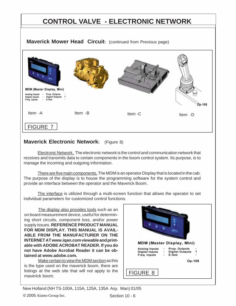
© 2005 Alamo Group Inc. Section 10 - 6
New Holland (NH TS-100A, 115A, 125A, 135A Asy. Man) 01/05
CONTROL VALVE - ELECTRONIC NETWORK
Maverick Mower Head Circuit: (continued from Previous page)
Item -DItem -CItem -BItem -A
FIGURE 7
Maverick Electronic Network: (Figure 8)
Electronic Network. The electronic network is the control and communication network thatreceives and transmits data to certain components in the boom control system. Its purpose, is tomanage the incoming and outgoing information.
There are five main components. The MDM is an operator Display that is located in the cab.The purpose of the display is to house the programming software for the system control andprovide an interface between the operator and the Maverick Boom.
The interface is utilized through a multi-screen function that allows the operator to setindividual parameters for customized control functions.
The display also provides tools such as anon board measurement device, useful for determin-ing short circuits, component loss, and/or powersupply issues. REFERENCE PRODUCT MANUALFOR MDM DISPLAY. THIS MANUAL IS AVAIL-ABLE FROM THE MANUFACTURER ON THEINTERNET AT www.iqan.com viewable and print-able with ADOBE ACROBAT READER. If you donot have Adobe Acrobat Reader it can be ob-tained at www.adobe.com.
Make certain to view the MDM section as thisis the type used on the maverick boom, there arelistings at the web site that will not apply to themaverick boom. FIGURE 8

© 2005 Alamo Group Inc. Section 10 - 7
New Holland (NH TS-100A, 115A, 125A, 135A Asy. Man) 01/05
CONTROL VALVE - ELECTRONIC NETWORK
Maverick Electronic Network:( continued)
The XP2 The XP2 is a controller modulethat is mounted at the front of the tractor next to themaverick control valve. The function of this compo-nent is to provide a gateway for incoming and outgo-ing information. Information is sent via the network tothis module in order to provide control of the sole-noids for valve operation (See Figure 9) REFER-ENCE PRODUCT MANUAL FOR MDM DISPLAY.THIS MANUAL IS AVAILABLE FROM THE MANU-FACTURER ON THE INTERNET ATwww.iqan.com viewable and printable withADOBE ACROBAT READER. If you do not haveAdobe Acrobat Reader it can be obtained atwww.adobe.com.
The XT2. The XT2 is also a controller mod-ule that is mounted at the front of the tractor on theside of the tank, The function of this component is toprovide a gateway for incoming and outgoing infor-mation. This module receives input from instrumen-tation, then provides that information to the networkfor further utilization. (See Figure 10) REFER-ENCE PRODUCT MANUAL FOR MDM DISPLAY.THIS MANUAL IS AVAILABLE FROM THE MANU-FACTURER ON THE INTERNET ATwww.iqan.com viewable and printable withADOBE ACROBAT READER. If you do not haveAdobe Acrobat Reader it can be obtained atwww.adobe.com.
The XS The XS is expansion module thatprovides extra input and output capabilities in orderto gain more flexibility on the network (See Figure11). The XS is responsible for receiving the signalsfrom the joystick and other in cab inputs and makingthem available on the network. REFERENCEPRODUCT MANUAL FOR MDM DISPLAY. THISMANUAL IS AVAILABLE FROM THE MANUFAC-TURER ON THE INTERNET AT www.iqan.comviewable and printable with ADOBE ACROBATREADER. If you do not have Adobe AcrobatReader it can be obtained at www.adobe.com. FIGURE 11
FIGURE 9
FIGURE 10

© 2005 Alamo Group Inc. Section 10 - 8
New Holland (NH TS-100A, 115A, 125A, 135A Asy. Man) 01/05
CONTROL VALVE - INSTRUMENTATION
Maverick Instrumentation:
Instrumentation The Maverick Boom uti-lizes instrumentation for certain decision makingactivities. Listed below are the sensors included onthis unit. Tank Temperature Sensor, Charge Pres-sure Filter Switch, Valve Pressure Filter Switch andReturn Filter Switch.
Tank Temperature Sensor. The tank tem-perature sensor monitors the fluid temperature inthe area of the pump suction screens. the tempera-ture is real time and is used on the network toaccomplish certain objectives. The first, is to displayon the interface while the cutter circuit is operating.The second, is to be used to control the electric fanon the hydraulic cooler. At any time the fluid levelreaches 150° F. the fan is activated and remainsactivated until fluid temperature drops to or belowthe desired temperature (See Figure 12).
The Charge Pressure Filter Switch Thecharge pressure filter switch is located at the filter inthe charge loop on the hydrostatic pump (See Figure13). The sensor monitors the back pressure createdby the filter element when in use. When the backpressure reaches a setting of 50 psi the switch willtrigger and prompt the operator for a filter elementchange of filter element.
The Valve Pressure Filter Switch TheValve pressure filter switch is located at the pres-sure filter in the valve pressure circuit, between theclosed center load sense pump and the controlvalve (See Figure 14). The sensor monitors the backpressure created by the filter element when in use.When the back pressure reaches a setting of 50 psithe switch will trigger and prompt the operator for afilter element change.
WARNING! This filter does not have a by-pass. The element must be changed at theappropriate time to avoid element danmage andsystem contamination.
FIGURE 12
FIGURE 13
FIGURE 14

© 2005 Alamo Group Inc. Section 10 - 9
New Holland (NH TS-100A, 115A, 125A, 135A Asy. Man) 01/05
Maverick Instrumentation:(continued)
The Return Filter Switch. The return filterswitch is located at the return filter mounted on to thetank top. The fluid returning from the cylinder controlvalve is filtered before returning to tank at this loca-tion (See Figure 15). The sensor monitors backpressure created by the filter assembly while cylin-der circuit is in operation. When the back pressurereaches 25 psi the switch will trigger and prompt theoperator for a filter element change.
WARNING! This filter does not have a by-pass. The element must be changed at theappropriate time to avoid element damage andsystem contamination.
CONTROL VALVE - INSTRUMENTATION
FIGURE 15
Maverick Operator Interface :
The Operator Interface The operator selects parameters provided by a menu system in theMDM display control box. The parameters are used to establish how the boom unit functions. The menusystem is comprised of two sections. The first section is setup, the second section powers up the boomcontrol circuit and cutter head circuit. The following steps outline how to successfully page through themenu system to execute operation. See the end of this section for Joystick control operation after startup procedure is completed.
Executing Set-Up The following representations will outline the steps necessary to executeset-up.
* Key Escape or back at anytime to revert to the previous screen or restart the set-up menu at any time.
* Key F-1 to access the set-up menu.
* Key the corresponding F-key to establish the desired boom speed. This parameter isprovided for customizable operation.

© 2005 Alamo Group Inc. Section 10 - 10
New Holland (NH TS-100A, 115A, 125A, 135A Asy. Man) 01/05
CONTROL VALVE - INSTRUMENTATION
Maverick Operator Interface : (continued)
* Key the corresponding F-key for the head attachment that will be used, This is an important stepbecause this parameter chooses which direction the fluid will enter the motor. The Timbercat Sicklebarmower is the only head attachment that currently requires the operator to send reverse flow, for allothers chose F-1 key for standard directional flow.
* Key F-1 to activate Joystick, the Boom will not move until the joystick is activated. The Boom functionSet-up is now complete, the boom speed, the head attachment has been chosen and the joystick hasbeen activated.
* Key F-1 to power motor. This is best done when the engine RPM is at idle speed. Doing this a t highRPM will cause the system pressure to surge sending fluid over the relief and causing excess heat tobe introduced into the system.
* At any time the Cutter Head Motor E-Stop (emergency stop) can be pushed to disable the motorcircuit. If this is done the Switch must be raised in the run position before the motor circuit can bereactivated.

© 2005 Alamo Group Inc. Section 10 - 11
New Holland (NH TS-100A, 115A, 125A, 135A Asy. Man) 01/05
CONTROL VALVE - INSTRUMENTATIONMaverick Operator Interface : (continued)
* At this time the motor circuit is powered and the mower head motor is active. This screen also showsthe tank temperature in degrees Fahrenheit. To turn off the motor at this time Key F-1.
* The Joystick Master control switch must be off to prevent accidental movement of boom and cuttinghead when ever mower is not being operated, such as when in transport.
Cylinder Supply Pump PressureAdjust (If Needed):
Special Note: If after setting the displaycontrols, check to make certain that functionsoperate correctly. If the Boom will not lift. The Pumpfor the Cylinder supply may have to be adjusted.This is a simple process that will require a 7/16"wrench for this adjustment and a 1/2" wrench for thelocking nut. Looking on the LH side of the pumpthere are two adjustments, one has a 7/16" hexhead and the other a ridged round head, Only adjustthe one with the hex head. DO NOT adjust orchange the round ridged adjustment as it is set fromthe factory. Adjust the 7/16" hex one by turning it intill it seats completely (Do not force adjustment afteris seats). Then back it back out 1/2 turn, this will giveyou the 2800 psi required to operate the boom. (SeeFigure 16 & 17). Hold the adjusting nut while turningthe locking nut so the adjustment nut does not turnwith it changing the setting.
Pressure Adjust Nut (7/16" Hex)&
Locking Nut (1/2" Hex)
Pressure AdjustControl (7/16" Hex)
FIGURE 16
FIGURE 17

© 2005 Alamo Group Inc. Section 10 - 12
New Holland (NH TS-100A, 115A, 125A, 135A Asy. Man) 01/05
JOYSTICK FUNCTIONS: (Figure 18)To operate a function the following series of events must work.
1. The Joystick Controller is moved in the correct direction the required distance, During its movementan electrical signal is sent to the electric Controller in the proper Valve Section of the Control Valve.
2. The Electric Controller sends an electrical signal, which causes the Proportional Control Valves toactuate the proper amount based on the signal from the Controller. EXAMPLE: Valves 1 & 3 allowPilot Pressure Oil to flow to the corresponding end of the Spool, Thus causing it to move. Valves 2& 4 allow the Oil from the opposite end of the Spool to return to the Tank. (NOTE: Lift, Swing andDipper functions are Proportional, Door and Tilt functions are “ON” or “Off” Only, See later sectionfor explanation of Proportional).
3. The Spool position Transducer sends an electrical signal to the Electronic Controller which indicatesthe position of the Spool.
4. The Electronic Controller will continue to adjust the Valves (1 - 4) in order to maintain an equilibriumbetween the Joystick signal and the feedback signal.
5. Reaction time from the time the Joystick is moved until the Spool moves is approximately 300milliseconds.
Joystick Functions
Push Buttons OnlyTop Left = Swivel CWTop Right = Swivel CCWBottom Left = Tilt UpBotom Right = Tilt Down
Push Button & Trigger SwitchTop Left = Door OpenTop Right = Door Close
Handle MovementPush Front = Lift DownPull Back = Lift UpPush Right = Dipper UpPush Left = Dipper DownRotate Right = Swing BackRotate Left = Swing Forward
Trigger & Handle MovementPush Right = Telescope OutPush Left = Telescope In
Trigger + Dipper = TelescopeTrigger + Swivel = Door
Trigger
LiftDown
DipperDown
TeleIn
LiftUp
SwingIn
DipperUp
TeleOut
SwingOut
Run
E-Stop
StopFIGURE 18
The Joystick is P/N 02981374. The Plug in connections are marked with numbers on the plastic plug.The wires are solid color or a color with a stripe. The Plugs should not fit but one way and that is bymatching the codes on the plugs.
CONTROL VALVE - JOYSTICK

© 2005 Alamo Group Inc. Section 10 - 13
New Holland (NH TS-100A, 115A, 125A, 135A Asy. Man) 01/05
Install Front Pump & Tank Cover
Install Front Pump & Tank Cover:
1. Install The Front Pump / Tank Cover. The frontcover and tank cover are a bolt on part. The hinges aremade onto the cover and the other half of the hinges aremade on the tank mount bracket. There are two bolts (oneeach hinge) that bolt the two hinge halves together. Theis a safety cable that will bolt to the cover and the tankmount bracket, this is to prevent the cover from openingto far forward and hitting the ground.
There are retaining latches that will bolt to the tankmount bracket and the cover. The holes for the fastenerswill have to drilled by the installation technician in the tankmount brackets and the front cover. (See Figure 19, 20,21 & 22) FIGURE 19
FIGURE 20 FIGURE 21
FIGURE 22

© 2005 Alamo Group Inc. Section 10 - 14
New Holland (NH TS-100A, 115A, 125A, 135A Asy. Man) 01/05
Adjust Boom Swing Stop
CAUTION ! You MUST READ and UNDERSTAND thissection as it is critcal BEFORE attempting to put boom rest positionthe first time. FAILURE TO PERFORM THIS ADJUSTMENT could causedamage to the cab of the tractor.
Boom Swing Adjustment:1. Boom Swing Stop Location. The boom Stop adjust-ment cannot be seen from the top of the turret assembly (SeeFigure 23). If the bottom cover plate (See Item 24) is notalready removed it will need to be, it is bolted on from theunder side of the turret assembly. From the under side youwill see the swing cylinders and cylinder pivot mounts (SeeFigure 25).
2. The Swing Stop Lug which is part of the TurretCylinder Link Weldment (See Figure 27). On the side towardthe rear there will be a lug with a bolt and locking nut in it (SeeFigure 27). Loosen the bolt and locking nut, turn the boltoutward.
3. Swinging Boom, DO NOT Swing Boom until theboom has been run with it sticking out away from tractor andall electronic control adjustments have been done. Theboom must be working smoothly. Slowly (with low engineRPM) with some one guiding you swing boom inward towardcab until the boom rest lug is aligned with the boom rest pin(See Figure 26). Set boom securely down over pin.
4. Final Swing Stop Adjustment. Unscrew the stop bolt(See Figure 27) until the head is against the swing stop lug ofthe turret cylinder link weldment (See Figure 27). Hold thebolt so it won't turn tighten the locking nut down against theturret stop swing lug. Recheck to make certain the boom willnot hit the cab of the tractor. It will stop at the turret stop lug
Figure 24
Figure 23
Figure 25 Figure 26
when properlyadjusted. Thismay have to beadjusted morethan once,NEVER allowunit to be run ifBoom will hitthe cab, this willdamage cab.
BoomRestLug Boom
RestPin
BottomTurretCover
TurretAssembly
SwingCylinders

© 2005 Alamo Group Inc. Section 10 - 15
New Holland (NH TS-100A, 115A, 125A, 135A Asy. Man) 01/05
Adjust Boom Swing Stop
Swing Stop LugBuilt onto theTurret CylinderLink Weldment
Turret Assembly as seen from the bottom
Turret Swing Stop Lug withAdjusting Bolt & Locking Nut
SwingCylinders
Figure 27

© 2005 Alamo Group Inc. Section 10 - 16
New Holland (NH TS-100A, 115A, 125A, 135A Asy. Man) 01/05
NOTES

© 2004 Alamo Group Inc. 11 - 1Maverick (NH TS-100A,115A, 125A, 135A Asy. Man) 01/05
MaverickNew Holland Tractor
TS-100A, 115A, 125A, 135A
Mounting Specifications
Section 11

© 2004 Alamo Group Inc. 11 - 2
Maverick (NH TS-100A,115A, 125A, 135A Asy. Man) 01/05
Mounting Specifications
New Holland TS-100A / 115A / 125A / 135A Cab/2&4wd
As of 01-05-05
10.00-16SL (F-2) Min / 11.00-16SL (F-2M) Max 2wd Front Tire12.4-24 (R-1) Min / 14.9-24 (R-1W) Max 4wd Front Tire18.4-30 (R-1) Min / 18.4-34 (R-1W) Max Rear Tire
Mount Kits:24' Maverick 2wd* Mount Kit ………………........ 02982343 (Page 11-7 thru 11-10)24' Maverick 4wd Mount Kit …………………...... 02982341 (Page 11-11 thru 11-14)30' Maverick 4wd** Mount Kit ……………...…... 02981892 (Page 11-15 thru 11-18)
Common pParts Box:Common Parts Box................. ……………..……..02981781 (Page 11-4 thru 11-6)(Common Parts Box shipped with all models no matter which boom or tractor model)
* 2wd tractors must be equipped with heavy duty, eight bolt front wheel hubs & spindles** 30' Maverick booms must be mounted on 4wd tractors only due to front axle spindleloading.
Options:Extra Maverick Installation Manual …………..…… 02982279
Standard Features:1. Modified exhaust pipe for boom transport clearance.2. Replacement arm rest with joystick console.3. Neapco style driveline with double U-joints.4. 1400# wheel weight plus 408# auxiliary weight kit.5. Right hand replacement Lexan door 3/8" Lexan replacement door (right side only). (See Figure 4)6. 51 gallon replacement fuel tank.7. ~10" of ground clearance with the min. tire size shown.
Restriction Notes:1. Exhaust must be modified for clearance. (See Figure 1)2. Battery box must be relocated by installing battery relocation brackets . (See Figure 3)3. Factory Seat Arm rest (RH Side) will be replaced by metal arm rest joystick mount. (See Figure 2)4. Electronic components and display modules will have to be mounted in cab. (See Figure 5), these
must be mounted inside Cab to keep them protected from weather.5. Display must be set to correct operating parameters before unit will function (See Figure 6).
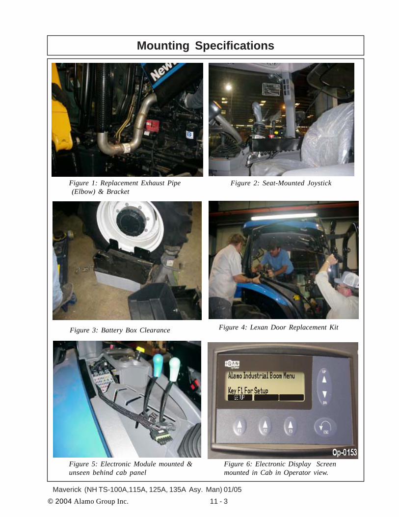
© 2004 Alamo Group Inc. 11 - 3Maverick (NH TS-100A,115A, 125A, 135A Asy. Man) 01/05
Figure 1: Replacement Exhaust Pipe (Elbow) & Bracket
Figure 2: Seat-Mounted Joystick
Figure 3: Battery Box Clearance
Mounting Specifications
Figure 4: Lexan Door Replacement Kit
Figure 5: Electronic Module mounted &unseen behind cab panel
Figure 6: Electronic Display Screenmounted in Cab in Operator view.

© 2004 Alamo Group Inc. 11 - 4
Maverick (NH TS-100A,115A, 125A, 135A Asy. Man) 01/05
Common Box - Component ListIMPORTANT NOTICE; These are parts that are shipped with every unit, these parts will remainthe same no matter which size boom is used or which model tractor is used. DO NOT order any of theseparts unless you are certain that that is what you want, most theses a are complete assemblies and maycontain more prts than are wanted to perform repairs. If ordering parts that are listed here it is recommendedthat you look the parts in a regular parts manual under the specific assembly number.
02981781 Common box Consist of the Following Items:ITEM PART NO. QTY. DESCRITION1. 00037200 7 LOCKNUT, TOPLOCK 3/4”-NC2. 02981381 1 PUMP COVER ASSEMBLY3. 02959924 12 LOCKNUT, TOPLOCK 1/4”-NC PLB4. 10058000 10 BOLT, HEX HEAD 1/4”-NC X 1” PL GR55. 02981441 2 KNOB, CR30 X 1-1/2” STUD6. 00024100 6 FLATWASHER, 1/4” PL STD7. 00992000 3.3 CABLE, 1/4” AIRCRAFT (7X19)8. 00001000 2 CABLE CLAMP9. 02981377 1 OIL COOLER ASY W/ FAN10. 00015800 8 LOCKNUT, TOPLOCK 3/8”-NC11. 00011100 12 FLATWASHER, 3/8” STD12. 02981383 1 COOLER MOUNT, RH13. 02981384 1 COOLER MOUNT, LH14. 02090800 2 ADAPTER, HYD ELBOW 12MB - 12MJ90°15. 02962181 6 ADAPTER, HYD STRAIGHT16. 02977622 1 DIVERTER SOLENOID VALVE17. 02981803 1 VALVE AND HYD TANK ASY (Includes the Next 47 Items)
02981373 1 INDICATOR, ELEC W/PACKARD02981704 1 MOUNT, MODULE03200762 1 ADAPTER, HYD ELBOW 6MB - 4MJ 90°02962181 2 ADAPTER, HYD, STRAIGHT00015800 7 LOCKNUT, TOPLOCK 3/8”00011100 5 FLATWASHER , 3/8” STD00753642 7 BOLT, HEX HEAD 3/8” -NC X 1-1/4” PL GR502964135 1 ADAPTER, HYD STRAIGHT02090800 4 ADAPTER, HYD ELBOW 12MB-12MJ90°02981371 1 FILTER, MEDIUM PRESSURE00001800 4 LOCKNUT, TOPLOCK 1/2”-NC PLB02981436 1 KIT, FLANGE 20, CODE 6102981463 1 ADAPTER, FLANGE 1-1/4” X 20MJ 45°02981468 1 BRACKET, SHIPPING ONLY00002700 2 FLATWASHER, 1/2” PL STD00001300 4 LOCKWASHER, 1/2”02892000 6 BOLT, HEX HEAD 1/2"-13 NC X 1-1/2" PL GR802968923 1 FILTER ASY, PRES ELEMENT63042700 1 ADAPTER, HYD, STRAIGHT03200587 1 PLUG, HEX HEAD #8MB02981372 1 FILTER, HEAD W/IND PORT02822700 1 ADAPTER, HYD ELBOW
Continued Next Page

© 2004 Alamo Group Inc. 11 - 5Maverick (NH TS-100A,115A, 125A, 135A Asy. Man) 01/05
02981781 Common box Consist of the Following Items: (Contiuned from previous page)ITEM PART NO. QTY. DESCRITION
02968167 1 ADAPTER, HYD STRAIGHT 16MB - 8MJ02981435 1 ADAPTER, HYD 10MB - 10 FJX90 ST02043600 2 ADAPTER, HYD ELBOW 16MB -16MJ45°02981369 1 PUMP, LS VARIABLE DISP02978986 1 PUMP, MED DUTY HYDROSTAT02981388 1 TANK ASY, HYDRAULIC02981427 1 HOSE, # 8 - 8FJX - 8FJX90 - 24” LG02981428 1 HOSE, # 8 - 8FJX - 8FJX90° - 21” LG02981429 1 HOSE, # 12 - 12FJX - 12FJX - 23” LG02981430 1 HOSE, # 12 - 12FJX - 12FJX - 31” LG02981431 1 HOSE, # 4 - 4FJX - 4FJX90 - 35” LG02981432 1 HOSE, # 4 - 4FJX - 4FJX90 - 20” LG02981433 1 HOSE, # 20 - 20FJX - 20FJX - 24” LG02981462 1 HOSE, # 12 - 12FJX - 12FJX90 - 20” LG.02981986 1 DECAL, HOSE & ELEC CONNECTION02979473 1 DECAL, AW ISO VG 10002971123 1 DECAL, WARNING PRESSURIZED TANK02965262 1 DECAL, WARNING HOSE BURST02971943 1 DECAL, ALAMO IND YELLOW02981888 1 ASY, VALVE & FITTINGS02968896 1 PLASTIC TIE, ORANGE 11LG02968894 1 PLASTIC TIE, RED 11LG02971943 1 DECAL, ALAMO IND YELLOW02982347 1 ADAPTER, HYD 16MB - 10MJ STRAIGHT02972064 1 ADAPTER, HYD ELBOW 16MB - 8MJIC 90°
18. 02981805 1 ELECTRONIC KIT (includes the following 9 items)02981374 1 CONTROLLER, 3/AXIS 5 BUTTON02981375 1 HARNESS, WIRE, CONTROLS02981376 1 HOUSING, DISPLAY & SWITCH02981531 1 MODULE, XP2, EXPANSION02981532 1 MODULE, XT2, EXPANSION02981533 1 MODULE, XS, EXPANSION02964028A 1 SWITCH, PUSH PULL02982252 1 DWG, INST MAVERICK HARNESS02982340 1 ASY, MDM MODULE & PROGRAM
19. 02981517 2 BOLT, EYE TURNED 1/4”-NC20 X 1”20. 02976531 10 ADAPTER, HYD ELBOW 6FJX - 6FJX45°21. 02981953 5 HOSE HANGER, FORMED22. 02981787 1 BOLT, HEX HEAD 3/4”-NC X 1-1/2” PL GR823. 02981988 2 DECAL, JOYSTICK OPERATION24. 02981992A 1 OPERATORS MANUAL & PARTS MANUAL ASSEMBLY25. 02918600 6 BOLT, HEX HEAD 3/4”-10NC X 2” PL GR826. 00011400 4 BOLT, HEX HEAD 3/8”-NC X 1”
Common Box - Component List
Continued Next Page

© 2004 Alamo Group Inc. 11 - 6
Maverick (NH TS-100A,115A, 125A, 135A Asy. Man) 01/05
02981781 Common box Consist of the Following Items: (Contiuned from previous page)ITEM PART NO. QTY. DESCRITION26. 00011400 4 BOLT, HEX HEAD 3/8”-NC X 1”27. 00023100 4 BOLT, HEX HEAD 3/8”-NC X 1-1/2” PL GR528. 00017000 2 LOCKWASHER, 1/4” PL STD29. 00776031 1 CANISTER, F/ MANUALS30. 00776481 1 DECAL SHEET, CANNISTER MANUAL31. 02977417 1 DECAL, OPERATORS MANUAL INSIDE32. 107079 1 WIRE, BLACK 14 GA. X 24” LONG33. 02982339 2 OVAL SLEEVE, 5/32” DIA.34. D377 1 BOOKLET, DECAL BOOM MOWER35. 02981822 1 HOSE BRACKET WELDMENT36. 00019600 1 LOCKWASHER. 1/2” HEAVY PL37. 02892000 1 BOLT, HEX HEAD 1/2”-13NC X 1-1/2” PL GR838. 02981992CA 1 MANUAL CANNISTER ASSEMBLY
Common Box - Component List

© 2004 Alamo Group Inc. 11 - 7Maverick (NH TS-100A,115A, 125A, 135A Asy. Man) 01/05
New HollandTS-100A / 115A / 125A / 135ACab & 2wd
Mounting Component ID 24 ft. Cab & 2wd
IMPORTANT NOTICE: The following Part / Assembly Numbers are for reference andshould not be ordered as replacement parts, unless all the components in that assembly arewanted. These will break down to bills of material of the components. Some of numbers listed areNOT individual Parts but complete assemblies and/or box of assemblies. Check before ordering.
24 foot Maverick 2wd* Mount Kit(* 2wd tractors must be equipped with heavy duty, eight bolt front wheel hubs & spindles)
02982343 Maverick Mount Kit - NH TS-100A/115A/125A/135A Cab 2 wd:Consist of the Following Items
Item Part No. Qty Description1. 02980888 1 LEXAN REPLACEMENT DOOR KIT, RH SIDE2. 02971789 1 WHEEL WEIGHT KIT, 1400 LBS.3. 02976671 1 AUXILLARY WHEEL WEIGHT KIT 408LBS.4. 02980938 1 REPLACEMENT FUEL TANK KIT5. 02982005 1 RAIL WELDMENT, RH REAR6. 02982006 1 RAIL WELDMENT, LH REAR7. 02982014 1 RAIL WELDMENT, RH FRONT8. 02982015 1 RAIL WELDMENT, LH FRONT9. 02982314 1 BOOM REST WELDMENT10. 02982344 1 COMPONENT BOX
02982344 Component Box: Consist of the following Item No.Item Part No. Qty Description1 02980699 1 PULLEY ADAPTER NH TS-A2 02980719 1 ASSY, TS-A PUMP MOUNT W/COVER3 02980694 1 PLATE, BOOM REST STABILIZER4 02980916 1 KIT, EXHAUST RELOCATION TS115A5 02981750 1 KIT, BATTERY RELOCATION6 02982000 1 DRIVELINE, MODIFIED 02975257A7 02982157 1 HOSE BUNDLE 6 CYL MAVERICK
Continued next page

© 2004 Alamo Group Inc. 11 - 8
Maverick (NH TS-100A,115A, 125A, 135A Asy. Man) 01/05
02982344 Component Box: Consist of the following Item No.Continued from previous pageItem Part No. Qty Description8 02981404 1 MOUNT, TANK, RAIL, RH,TSA9 02981405 1 MOUNT, TANK, RAIL, LH,TSA10 02982022 1 WLDMT. BOOM REST STABILIZER11 02981415 1 WELDMENT, ARMREST, CONTROLLER12 02982279 1 INST MANUAL, NH TS-A MAVERICK13 02981464 1 ASY, MOUNT PUMP COVER TSA14 02982292 1 HOSE #12-12FJX-12FJX-24LG15 02982324 1 PLATE, IQAN MOUNT16 02982345 1 BOLT BAG, NH TS115A C/2 MV24Component Box P/N 02982344 is in Mount Kit P/N 02982343
02982345 Bolt Bag: Consist of the following Item No.
Item Part No. Qty Description1 02980967 4 BOLT, HEX HEAD M12-P1.75 X 60mm PL GR10.92 00754566 4 LOCKWASHER, 12MM3 02976344 4 BOLT, HEX HEAD 7/16”-NC X 1-1/4” PL GR84 00022200 4 LOCKWASHER, 7/16” PL5 02975692 18 BOLT, HEX HEAD M20-P2.5 X 50MM PL GR10.96 02971158 18 LOCKWASHER, 20MM7 00059500 4 NUT, HEX 1”-NC PL8 02032200 4 LOCKWASHER STD,1”9 02980723 8 BOLT, HEX HEAD M18-P1.5 X 80 PL GR10.910 02970066 8 LOCKWASHER, 18MM11 02959587 2 BOLT, HEX HEAD, 3/4”-10NC X 6" PL GR812 00037200 26 LOCKNUT, 3/4”-NC13 02960521 4 BOLT, HEX HEAD 3/4”-NC X 2-3/4” PL GR814 5312316 70 WASHER, 3/4" (20 MM) HARDENED15 02963646 4 BOLT, HEX HEAD 3/4”-NC X 2-1/2” PL GR816 00748547 7 FLATWASHER, 1-1/32” X 2-3/16” X .22” HARDENED17 02981985 8 WASHER,18MM HARDENED18 02966556 3 BOLT, HEX HEAD 1"-NC X 11" PL GR819 02972088 8 BOLT, HEX HEAD 3/4”-NC X 3-1/2” PL GR820 02980721 1 BOLT, HEX HEAD 1"-8UNC X 10-1/2” PL GR821 02918600 8 BOLT, HEX HEAD 3/4”-10UNC X 2” PL GR822 00759457 4 BOLT, LAG 5/16” X 2” PL GR523 00011700 4 LOCKWASHER, 5/16 PL STD24 00762398 2 BOLT, HEX HEAD M10-P1.5 X 30mm PL GR8.825 00755954 2 LOCKWASHER, M10 SPRINGBolt Bag P/N 02982345 is in Component Box P/N 02982344 which is inMount Kit P/N 02982343
Mounting Component ID 24 ft. Cab & 2wd
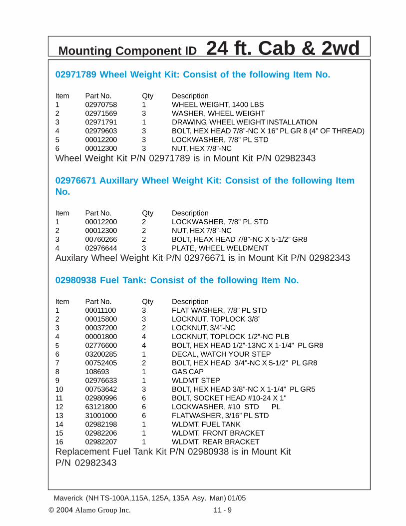
© 2004 Alamo Group Inc. 11 - 9Maverick (NH TS-100A,115A, 125A, 135A Asy. Man) 01/05
02971789 Wheel Weight Kit: Consist of the following Item No.
Item Part No. Qty Description1 02970758 1 WHEEL WEIGHT, 1400 LBS2 02971569 3 WASHER, WHEEL WEIGHT3 02971791 1 DRAWING, WHEEL WEIGHT INSTALLATION4 02979603 3 BOLT, HEX HEAD 7/8”-NC X 16” PL GR 8 (4” OF THREAD)5 00012200 3 LOCKWASHER, 7/8” PL STD6 00012300 3 NUT, HEX 7/8”-NCWheel Weight Kit P/N 02971789 is in Mount Kit P/N 02982343
02976671 Auxillary Wheel Weight Kit: Consist of the following ItemNo.
Item Part No. Qty Description1 00012200 2 LOCKWASHER, 7/8” PL STD2 00012300 2 NUT, HEX 7/8”-NC3 00760266 2 BOLT, HEAX HEAD 7/8”-NC X 5-1/2” GR84 02976644 3 PLATE, WHEEL WELDMENTAuxilary Wheel Weight Kit P/N 02976671 is in Mount Kit P/N 02982343
02980938 Fuel Tank: Consist of the following Item No.
Item Part No. Qty Description1 00011100 3 FLAT WASHER, 7/8” PL STD2 00015800 3 LOCKNUT, TOPLOCK 3/8”3 00037200 2 LOCKNUT, 3/4”-NC4 00001800 4 LOCKNUT, TOPLOCK 1/2”-NC PLB5 02776600 4 BOLT, HEX HEAD 1/2”-13NC X 1-1/4" PL GR86 03200285 1 DECAL, WATCH YOUR STEP7 00752405 2 BOLT, HEX HEAD 3/4”-NC X 5-1/2” PL GR88 108693 1 GAS CAP9 02976633 1 WLDMT STEP10 00753642 3 BOLT, HEX HEAD 3/8”-NC X 1-1/4” PL GR511 02980996 6 BOLT, SOCKET HEAD #10-24 X 1"12 63121800 6 LOCKWASHER, #10 STD PL13 31001000 6 FLATWASHER, 3/16” PL STD14 02982198 1 WLDMT. FUEL TANK15 02982206 1 WLDMT. FRONT BRACKET16 02982207 1 WLDMT. REAR BRACKETReplacement Fuel Tank Kit P/N 02980938 is in Mount KitP/N 02982343
Mounting Component ID 24 ft. Cab & 2wd
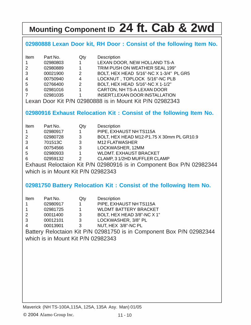
© 2004 Alamo Group Inc. 11 - 10
Maverick (NH TS-100A,115A, 125A, 135A Asy. Man) 01/05
02980888 Lexan Door kit, RH Door : Consist of the following Item No.
Item Part No. Qty Description1 02980803 1 LEXAN DOOR, NEW HOLLAND TS-A2 02980889 1 TRIM PUSH ON WEATHER SEAL 199"3 00021900 2 BOLT, HEX HEAD 5/16”-NC X 1-3/4” PL GR54 00750940 4 LOCKNUT , TOPLOCK 5/16”-NC PLB5 02766400 2 BOLT, HEX HEAD 5/16”-NC X 1-1/2”6 02981016 1 CARTON, NH TS-A LEXAN DOOR7 02981035 1 INSERT,LEXAN DOOR INSTALLATIONLexan Door Kit P/N 02980888 is in Mount Kit P/N 02982343
02980916 Exhaust Relocation Kit : Consist of the following Item No.
Item Part No. Qty Description1 02980917 1 PIPE, EXHAUST NH TS115A2 02980728 3 BOLT, HEX HEAD M12-P1.75 X 30mm PL GR10.93 701513C 3 M12 FLATWASHER4 00754566 3 LOCKWASHER, 12MM5 02980933 1 WLDMT. EXHAUST BRACKET6 02959132 2 CLAMP, 3 1/2HD MUFFLER CLAMPExhaust Reloctaion Kit P/N 02980916 is in Component Box P/N 02982344which is in Mount Kit P/N 02982343
02981750 Battery Relocation Kit : Consist of the following Item No.
Item Part No. Qty Description1 02980917 1 PIPE, EXHAUST NH TS115A1 02981725 1 WLDMT BATTERY BRACKET2 00011400 3 BOLT, HEX HEAD 3/8”-NC X 1”3 00012101 3 LOCKWASHER, 3/8” PL4 00013901 3 NUT, HEX 3/8”-NC PLBattery Reloctaion Kit P/N 02981750 is in Component Box P/N 02982344which is in Mount Kit P/N 02982343
Mounting Component ID 24 ft. Cab & 2wd

© 2004 Alamo Group Inc. 11 - 11Maverick (NH TS-100A,115A, 125A, 135A Asy. Man) 01/05
New HollandTS-100A / 115A /125A / 135ACab & 4wd
Page 1-8 thru 1-11
24 foot Maverick 4wdMount KiT Only
Mount Kit P/N 02982341
Mounting Component ID 24 ft. Cab & 4wd

© 2004 Alamo Group Inc. 11 - 12
Maverick (NH TS-100A,115A, 125A, 135A Asy. Man) 01/05
Mounting Component ID 24 ft. Cab & 4wdIMPORTANT NOTICE: The following Part / Assembly Numbers are for reference andshould not be ordered as replacement parts, unless all the components in that assembly arewanted. These will break down to bills of material of the components. Some of numbers listed areNOT individual Parts but complete assemblies and/or box of assemblies. Check before ordering.
24 foot Maverick 4wd Mount Kit
02982341 Maverick Mount Kit - NH TS-100A/115A/125A/135A Cab 4wd:Consist of the Following Items
Item Part No. Qty Description1. 02980888 1 LEXAN REPLACEMENT DOOR KIT, RH SIDE2. 02971789 1 WHEEL WEIGHT KIT, 1400 LBS.3. 02980938 1 REPLACEMENT FUEL TANK KIT4. 02982005 1 RAIL WELDMENT, RH REAR5. 02982006 1 RAIL WELDMENT, LH REAR6. 02982014 1 RAIL WELDMENT, RH FRONT7. 02982015 1 RAIL WELDMENT, LH FRONT8. 02982314 1 BOOM REST WELDMENT9. 02981893 1 COMPONENT BOX
02981893 Component Box: Consist of the following Item No.
Item Part No. Qty Description1 02980699 1 PULLEY ADAPTER NH TS-A2 02980719 1 ASSY, TS-A PUMP MOUNT W/COVER3 02980694 1 PLATE, BOOM REST STABILIZER4 02980916 1 KIT, EXHAUST RELOCATION TS115A5 02981750 1 KIT, BATTERY RELOCATION6 02982000 1 DRIVELINE, MODIFIED 02975257A7 02982157 1 HOSE BUNDLE 6 CYL MAVERICK8 02981404 1 MOUNT, TANK, RAIL, RH,TSA9 02981405 1 MOUNT, TANK, RAIL, LH,TSA10 02982022 1 WLDMT. BOOM REST STABILIZER11 02981415 1 WELDMENT, ARMREST, CONTROLLER12 02982279 1 INST MANUAL, NH TS-A MAVERICK13 02981464 1 ASY, MOUNT PUMP COVER TSA14 02982292 1 HOSE #12-12FJX-12FJX-24LG15 02982324 1 PLATE, IQAN MOUNT16 02981894 1 BOLT BAG, NH TS115A C/4MV17 02981895 1 TS-A FRONT AXLE STABILIZER KIT18 02982279 1 INSTALLATION MANUAL TS115A/125A/135A MAVERICKComponent Box P/N 02981893 is in Mount Kit P/N 02982341
New Holland TS-100A/115A/125A/135A Cab 4wd

© 2004 Alamo Group Inc. 11 - 13Maverick (NH TS-100A,115A, 125A, 135A Asy. Man) 01/05
02981894 Bolt Bag: Consist of the following Item No.
Item Part No. Qty Description1 02980967 4 BOLT, HEX HEAD M12-P1.75 X 60mm PL GR10.92 00754566 4 LOCKWASHER, 12MM3 02976344 4 BOLT, HEX HEAD 7/16”-NC X 1-1/4” PL GR84 00022200 4 LOCKWASHER, 7/16” PL5 02975692 14 BOLT, HEX HEAD M20-P2.5 X 50MM PL GR10.96 02971158 14 LOCKWASHER, 20MM7 00059500 4 NUT, HEX 1”-NC PL8 02032200 4 LOCKWASHER STD,1”9 02980723 8 BOLT, HEX HEAD M18-P1.5 X 80 PL GR10.910 02970066 8 LOCKWASHER, 18MM11 02959587 2 BOLT, HEX HEAD, 3/4”-10NC X 6" PL GR812 00037200 26 LOCKNUT, 3/4”-NC13 02960521 4 BOLT, HEX HEAD 3/4”-NC X 2-3/4” PL GR814 5312316 70 WASHER, 3/4" (20 MM) HARDENED15 02963646 4 BOLT, HEX HEAD 3/4”-NC X 2-1/2” PL GR816 00748547 7 FLATWASHER, 1-1/32” X 2-3/16” X .22” HARDENED17 02981985 8 WASHER,18MM HARDENED18 02966556 3 BOLT, HEX HEAD 1"-NC X 11" PL GR819 02972088 8 BOLT, HEX HEAD 3/4”-NC X 3-1/2” PL GR820 02980721 1 BOLT, HEX HEAD 1"-8UNC X 10-1/2” PL GR821 02918600 8 BOLT, HEX HEAD 3/4”-10UNC X 2” PL GR822 00759457 4 BOLT, LAG 5/16” X 2” PL GR523 00011700 4 LOCKWASHER, 5/16 PL STD24 00762398 2 BOLT, HEX HEAD M10-P1.5 X 30mm PL GR8.825 00755954 2 LOCKWASHER, M10 SPRINGBolt Bag P/N 02981894 is in Component Box P/N 02981893 which is inMount Kit P/N 02982341
02971789 Wheel Weight Kit: Consist of the following Item No.
Item Part No. Qty Description1 02970758 1 WHEEL WEIGHT, 1400 LBS2 02971569 3 WASHER, WHEEL WEIGHT3 02971791 1 DRAWING, WHEEL WEIGHT INSTALLATION4 02979603 3 BOLT, HEX HEAD 7/8”-NC X 16” PL GR 8 (4” OF THREAD)5 00012200 3 LOCKWASHER, 7/8” PL STD6 00012300 3 NUT, HEX 7/8”-NCWheel Weight Kit P/N 02971789 is in Mount Kit P/N 02982341
Mounting Component ID 24 ft. Cab & 4wd

© 2004 Alamo Group Inc. 11 - 14
Maverick (NH TS-100A,115A, 125A, 135A Asy. Man) 01/05
02980938 Fuel Tank: Consist of the following Item No.
Item Part No. Qty Description1 00011100 3 FLAT WASHER, 7/8” PL STD2 00015800 3 LOCKNUT, TOPLOCK 3/8”3 00037200 2 LOCKNUT, 3/4”-NC4 00001800 4 LOCKNUT, TOPLOCK 1/2”-NC PLB5 02776600 4 BOLT, HEX HEAD 1/2”-13NC X 1-1/4" PL GR86 03200285 1 DECAL, WATCH YOUR STEP7 00752405 2 BOLT, HEX HEAD 3/4”-NC X 5-1/2” PL GR88 108693 1 GAS CAP9 02976633 1 WLDMT STEP10 00753642 3 BOLT, HEX HEAD 3/8”-NC X 1-1/4” PL GR511 02980996 6 BOLT, SOCKET HEAD #10-24 X 1"12 63121800 6 LOCKWASHER, #10 STD PL13 31001000 6 FLATWASHER, 3/16” PL STD14 02982198 1 WLDMT. FUEL TANK15 02982206 1 WLDMT. FRONT BRACKET16 02982207 1 WLDMT. REAR BRACKETReplacement Fuel Tank Kit P/N 02980938 is in Mount KitP/N 02982341
02980888 Lexan Door kit, RH Door : Consist of the following Item No.
Item Part No. Qty Description1 02980803 1 LEXAN DOOR, NEW HOLLAND TS-A2 02980889 1 TRIM PUSH ON WEATHER SEAL 199"3 00021900 2 BOLT, HEX HEAD 5/16”-NC X 1-3/4” PL GR54 00750940 4 LOCKNUT , TOPLOCK 5/16”-NC PLB5 02766400 2 BOLT, HEX HEAD 5/16”-NC X 1-1/2”6 02981016 1 CARTON, NH TS-A LEXAN DOOR7 02981035 1 INSERT,LEXAN DOOR INSTALLATIONLexan Door Kit P/N 02980888 is in Mount Kit P/N 02982341
02980916 Exhaust Relocation Kit : Consist of the following Item No.
Item Part No. Qty Description1 02980917 1 PIPE, EXHAUST NH TS115A2 02980728 3 BOLT, HEX HEAD M12-P1.75 X 30mm PL GR10.93 701513C 3 M12 FLATWASHER4 00754566 3 LOCKWASHER, 12MM5 02980933 1 WLDMT. EXHAUST BRACKET6 02959132 2 CLAMP, 3 1/2HD MUFFLER CLAMPExhaust Reloctaion Kit P/N 02980916 is in Component Box P/N 02981893which is in Mount Kit P/N 02982341
Mounting Component ID 24 ft. Cab & 4wd

© 2004 Alamo Group Inc. 11 - 15Maverick (NH TS-100A,115A, 125A, 135A Asy. Man) 01/05
02981750 Battery Relocation Kit : Consist of the following Item No.
Item Part No. Qty Description1 02981725 1 WLDMT BATTERY BRACKET2 00011400 3 BOLT, HEX HEAD 3/8”-NC X 1”3 00012101 3 LOCKWASHER, 3/8” PL4 00013901 3 NUT, HEX 3/8”-NC PLBattery Reloctaion Kit P/N 02981750 is in Component Box P/N 02981893which is in Mount Kit P/N 02982341
02981895 TS-A Front Axle Stabilizer Kit : Consist of following Item No.
Item Part No. Qty Description1 02981316 1 CYLINDER, ASY2 02981896 1 ADAPTER HYD, REDUCER 6FJX - 4MJ3 02965166 1 ADAPTER HYD, TEE 6MJ - 6MJ - 6FJX4 02960018 1 ADAPTER HYD, ELBOW5 02960054 1 PLUG #4 MB W/T-VENT & O-RING6 001845 1 HOSE #4 - 4FJX - 4FJX90 70LG7 02983143 1 BRACKET WELDMENT, TOP8 02983144 1 BRACKET WELDMENT, BOTTOM9 02982320 1 CYLINDER SUPPORT WELDMENT10 00752716 2 BOLT, HEX HEAD 1/2”-NC X 3-1/2” PL GR811 7B101128 2 BOLT, HEX HEAD 5/8”-NC X 3-1/2” PL GR812 00695100 2 LOCKNUT, TOPLOCK 5/8”13 00001800 2 LOCKNUT, TOPLOCK 1/2”-NC PLB14 02975669 4 BOLT, HEX HEAD M20-P2.5 X 60MM PL GR10.915 02971158 4 LOCKWASHER, 20MMTS-A Front Axle Stabilizer Kit P/N 02981895 is in Component Box P/N02981893 which is in Mount Kit P/N 02982341
Mounting Component ID 24 ft. Cab & 4wd

© 2004 Alamo Group Inc. 11 - 16
Maverick (NH TS-100A,115A, 125A, 135A Asy. Man) 01/05
New HollandTS-100A / 115A /125A / 135ACab & 4wd
Page 1-12 thru 1-15
30 foot Maverick 4wd**Mount KiT Only
Mount Kit P/N 02981892
** 30' Maverick booms must be mounted on 4wd tractorsonly due to front axle spindle loading.
Mounting Component ID 30 ft. Cab & 4wd

© 2004 Alamo Group Inc. 11 - 17Maverick (NH TS-100A,115A, 125A, 135A Asy. Man) 01/05
IMPORTANT NOTICE: The following Part / Assembly Numbers are for reference andshould not be ordered as replacement parts, unless all the components in that assembly arewanted. These will break down to bills of material of the components. Some of numbers listed areNOT individual Parts but complete assemblies and/or box of assemblies. Check before ordering.
30 foot Maverick 4wd** Mount Kit** 30' Maverick booms must be mounted on 4wd tractors only due to front axle spindleloading.02981892 Maverick Mount Kit - NH TS-100A/115A/125A/135A Cab 4wd:Consist of the Following Items
Item Part No. Qty Description1. 02980888 1 LEXAN REPLACEMENT DOOR KIT, RH SIDE2. 02971789 1 WHEEL WEIGHT KIT, 1400 LBS.3. 02976671 1 AUXILLARY WHEEL WEIGHT KIT 408LBS.4. 02980938 1 REPLACEMENT FUEL TANK KIT5. 02982005 1 RAIL WELDMENT, RH REAR6. 02982006 1 RAIL WELDMENT, LH REAR7. 02982014 1 RAIL WELDMENT, RH FRONT8. 02982015 1 RAIL WELDMENT, LH FRONT9. 02982025 1 BOOM REST WELDMENT10. 02981893 1 COMPONENT BOX
02981893 Component Box: Consist of the following Item No.Item Part No. Qty Description1 02980699 1 PULLEY ADAPTER NH TS-A2 02980719 1 ASSY, TS-A PUMP MOUNT W/COVER3 02980694 1 PLATE, BOOM REST STABILIZER4 02980916 1 KIT, EXHAUST RELOCATION TS115A5 02981750 1 KIT, BATTERY RELOCATION6 02982000 1 DRIVELINE, MODIFIED 02975257A7 02982157 1 HOSE BUNDLE 6 CYL MAVERICK8 02981404 1 MOUNT, TANK, RAIL, RH,TSA9 02981405 1 MOUNT, TANK, RAIL, LH,TSA10 02982022 1 WLDMT. BOOM REST STABILIZER11 02981415 1 WELDMENT, ARMREST, CONTROLLER12 02982279 1 INST MANUAL, NH TS-A MAVERICK13 02981464 1 ASY, MOUNT PUMP COVER TSA14 02982292 1 HOSE #12-12FJX-12FJX-24LG15 02982324 1 PLATE, IQAN MOUNT16 02981894 1 BOLT BAG, NH TS115A C/4MV17 02981895 1 TS-A FRONT AXLE STABILIZER KIT18 02982279 1 INSTALLATION MANUAL TS115A/125A/135A MAVERICKComponent Box P/N 02981893 is in Mount Kit P/N 02981892
Mounting Component ID 30 ft. Cab & 4wdNew Holland TS-100A/115A/125A/135A Cab & 4wd

© 2004 Alamo Group Inc. 11 - 18
Maverick (NH TS-100A,115A, 125A, 135A Asy. Man) 01/05
02981894 Bolt Bag: Consist of the following Item No.
Item Part No. Qty Description1 02980967 4 BOLT, HEX HEAD M12-P1.75 X 60mm PL GR10.92 00754566 4 LOCKWASHER, 12MM3 02976344 4 BOLT, HEX HEAD 7/16”-NC X 1-1/4” PL GR84 00022200 4 LOCKWASHER, 7/16” PL5 02975692 14 BOLT, HEX HEAD M20-P2.5 X 50MM PL GR10.96 02971158 14 LOCKWASHER, 20MM7 00059500 4 NUT, HEX 1”-NC PL8 02032200 4 LOCKWASHER STD,1”9 02980723 8 BOLT, HEX HEAD M18-P1.5 X 80 PL GR10.910 02970066 8 LOCKWASHER, 18MM11 02959587 2 BOLT, HEX HEAD, 3/4”-10NC X 6" PL GR812 00037200 26 LOCKNUT, 3/4”-NC13 02960521 4 BOLT, HEX HEAD 3/4”-NC X 2-3/4” PL GR814 5312316 70 WASHER, 3/4" (20 MM) HARDENED15 02963646 4 BOLT, HEX HEAD 3/4”-NC X 2-1/2” PL GR816 00748547 7 FLATWASHER, 1-1/32” X 2-3/16” X .22” HARDENED17 02981985 8 WASHER,18MM HARDENED18 02966556 3 BOLT, HEX HEAD 1"-NC X 11" PL GR819 02972088 8 BOLT, HEX HEAD 3/4”-NC X 3-1/2” PL GR820 02980721 1 BOLT, HEX HEAD 1"-8UNC X 10-1/2” PL GR821 02918600 8 BOLT, HEX HEAD 3/4”-10UNC X 2” PL GR822 00759457 4 BOLT, LAG 5/16” X 2” PL GR523 00011700 4 LOCKWASHER, 5/16 PL STD24 00762398 2 BOLT, HEX HEAD M10-P1.5 X 30mm PL GR8.825 00755954 2 LOCKWASHER, M10 SPRINGBolt Bag P/N 02981894 is in Component Box P/N 02981893 which is inMount Kit P/N 02981892
02971789 Wheel Weight Kit: Consist of the following Item No.
Item Part No. Qty Description1 02970758 1 WHEEL WEIGHT, 1400 LBS2 02971569 3 WASHER, WHEEL WEIGHT3 02971791 1 DRAWING, WHEEL WEIGHT INSTALLATION4 02979603 3 BOLT, HEX HEAD 7/8”-NC X 16” PL GR 8 (4” OF THREAD)5 00012200 3 LOCKWASHER, 7/8” PL STD6 00012300 3 NUT, HEX 7/8”-NCWheel Weight Kit P/N 02971789 is in Mount Kit P/N 02981892
Mounting Component ID 30 ft. Cab & 4wd

© 2004 Alamo Group Inc. 11 - 19Maverick (NH TS-100A,115A, 125A, 135A Asy. Man) 01/05
02976671 Auxillary Wheel Weight Kit: Consist of the following Item No.
Item Part No. Qty Description1 00012200 2 LOCKWASHER, 7/8” PL STD2 00012300 2 NUT, HEX 7/8”-NC3 00760266 2 BOLT, HEAX HEAD 7/8”-NC X 5-1/2” GR84 02976644 3 PLATE, WHEEL WELDMENTAuxilary Wheel Weight Kit P/N 02976671 is in Mount Kit P/N 02981892
02980938 Fuel Tank: Consist of the following Item No.
Item Part No. Qty Description1 00011100 3 FLAT WASHER, 7/8” PL STD2 00015800 3 LOCKNUT, TOPLOCK 3/8”3 00037200 2 LOCKNUT, 3/4”-NC4 00001800 4 LOCKNUT, TOPLOCK 1/2”-NC PLB5 02776600 4 BOLT, HEX HEAD 1/2”-13NC X 1-1/4" PL GR86 03200285 1 DECAL, WATCH YOUR STEP7 00752405 2 BOLT, HEX HEAD 3/4”-NC X 5-1/2” PL GR88 108693 1 GAS CAP9 02976633 1 WLDMT STEP10 00753642 3 BOLT, HEX HEAD 3/8”-NC X 1-1/4” PL GR511 02980996 6 BOLT, SOCKET HEAD #10-24 X 1"12 63121800 6 LOCKWASHER, #10 STD PL13 31001000 6 FLATWASHER, 3/16” PL STD14 02982198 1 WLDMT. FUEL TANK15 02982206 1 WLDMT. FRONT BRACKET16 02982207 1 WLDMT. REAR BRACKETReplacement Fuel Tank Kit P/N 02980938 is in Mount KitP/N 02981892
02980888 Lexan Door kit, RH Door : Consist of the following Item No.
Item Part No. Qty Description1 02980803 1 LEXAN DOOR, NEW HOLLAND TS-A2 02980889 1 TRIM PUSH ON WEATHER SEAL 199"3 00021900 2 BOLT, HEX HEAD 5/16”-NC X 1-3/4” PL GR54 00750940 4 LOCKNUT , TOPLOCK 5/16”-NC PLB5 02766400 2 BOLT, HEX HEAD 5/16”-NC X 1-1/2”6 02981016 1 CARTON, NH TS-A LEXAN DOOR7 02981035 1 INSERT,LEXAN DOOR INSTALLATIONLexan Door Kit P/N 02980888 is in Mount Kit P/N 02981892
Mounting Component ID 30 ft. Cab & 4wd

© 2004 Alamo Group Inc. 11 - 20
Maverick (NH TS-100A,115A, 125A, 135A Asy. Man) 01/05
02980916 Exhaust Relocation Kit : Consist of the following Item No.
Item Part No. Qty Description1 02980917 1 PIPE, EXHAUST NH TS115A2 02980728 3 BOLT, HEX HEAD M12-P1.75 X 30mm PL GR10.93 701513C 3 M12 FLATWASHER4 00754566 3 LOCKWASHER, 12MM5 02980933 1 WLDMT. EXHAUST BRACKET6 02959132 2 CLAMP, 3 1/2HD MUFFLER CLAMPExhaust Reloctaion Kit P/N 02980916 is in Component Box P/N 02981893which is in Mount Kit P/N 02981892
02981750 Battery Relocation Kit : Consist of the following Item No.
Item Part No. Qty Description1 02981725 1 WLDMT BATTERY BRACKET2 00011400 3 BOLT, HEX HEAD 3/8”-NC X 1”3 00012101 3 LOCKWASHER, 3/8” PL4 00013901 3 NUT, HEX 3/8”-NC PLBattery Reloctaion Kit P/N 02981750 is in Component Box P/N 02981893which is in Mount Kit P/N 02981892
02981895 TS-A Front Axle Stabilizer Kit : Consist of following Item No.
Item Part No. Qty Description1 02981316 1 CYLINDER, ASY2 02981896 1 ADAPTER HYD, REDUCER 6FJX - 4MJ3 02965166 1 ADAPTER HYD, TEE 6MJ - 6MJ - 6FJX4 02960018 1 ADAPTER HYD, ELBOW5 02960054 1 PLUG #4 MB W/T-VENT & O-RING6 001845 1 HOSE #4 - 4FJX - 4FJX90 70LG7 02983143 1 BRACKET WELDMENT, TOP8 02983144 1 BRACKET WELDMENT, BOTTOM9 02982320 1 CYLINDER SUPPORT WELDMENT10 00752716 2 BOLT, HEX HEAD 1/2”-NC X 3-1/2” PL GR811 7B101128 2 BOLT, HEX HEAD 5/8”-NC X 3-1/2” PL GR812 00695100 2 LOCKNUT, TOPLOCK 5/8”13 00001800 2 LOCKNUT, TOPLOCK 1/2”-NC PLB14 02975669 4 BOLT, HEX HEAD M20-P2.5 X 60MM PL GR10.915 02971158 4 LOCKWASHER, 20MMTS-A Front Axle Stabilizer Kit P/N 02981895 is in Component Box P/N02981893 which is in Mount Kit P/N 02982341
Mounting Component ID 30 ft. Cab & 4wd

© 2004 Alamo Group Inc. 11 - 21Maverick (NH TS-100A,115A, 125A, 135A Asy. Man) 01/05
Item Part No. Qty Description
02981888 -- Valve & Fittings Asy, 6 Spool1 02981370 1 Valve Asy w/o Fittings2 02090800 2 Adapter Hyd, Elbow 12MB - 12MJ 90°3 02972177 11 Adapter Hyd, Straight 10MB - 6MJ4 03200284 1 Adapter Hyd, Straight 6MB - 4MJ5 02981889 1 Adapter Hyd, Straight 10MB - 6MJ6 02972208 1 Valve Solenoid Asy7 02975438 1 Adapter Hyd, Straight 8MB - 8FJX8 02981890 1 Adapter Hyd, Straight 8MB - 6MJ
Mounting Component ID - Control Valve Fittings

© 2004 Alamo Group Inc. 11 - 22
Maverick (NH TS-100A,115A, 125A, 135A Asy. Man) 01/05
Item Part No. Qty. Description
02972208 -- Solenoid Valve Asy1 02971425 1 Seal Kit, f/ solenoid Valve2 02975198 1 Coil, 12V- DC w/Dual 8-32NF Studs3 02975199 1 Cartridge, Solenoid Valve4 02975438 1 Adapter Hyd, Straight 8MB-6FJX5 02981890 1 Adapter Hyd, Straight 5MB - 6MJ
Mounting Component ID - Hydraulic Lock Valve

© 2004 Alamo Group Inc. 11 - 23Maverick (NH TS-100A,115A, 125A, 135A Asy. Man) 01/05
Mounting Component ID - DIVERTER VALVE
Door / Swing Cylinder Diverter Valve. Asy: P/N 02977622
The Diverter valve is a electrical operated valve that allows the hydraulic pressure to beshared to operate two (or more if valves are stacked) funtions with a single pressure supply. Thisvalve is strictly a diverter valve and is designed to direct the pressure, not regulate the flow orpressure.
The Port openings on this diverter valve are marked with letter number codes which showwich port is connected to which hose and where that hose connect on other end (See Figure 18)
Port Function & Connection
P1 Hose Hydraulic Pressure from Door / Swivel (B) Port on Control ValveP2 Hose Hydraulic Return to Door / Swivel (A) Port on Control ValveC1 Hose to Head Swivel Cylinder Base EndC2 Hose to Door Cylinder Base EndC3 Hose to Door Cylinder Rod EndC4 Hose to Head Swivel Cylinder Rod End
VS . 125/FC2
C3
SAE 4
P1P2
C1 Port thisside (NotSeen), to headswivel cyl baseend
C4 Port thisside (NotSeen), tohead swivelcyl rod endThese 4 holes are through holes
that would be used if this were astacking valve to stack two (ormore) valves together. These holesare not used in this application.
These 2 threaded holes on backside for mounting diverter valveto frame (Not Seen)
C2 Port, todoor cyl baseend
C3 Port, todoor cyl Rodend
P2 Port, Return to controlvalve door / swivel port ofcontrol valve
P1 Port, Pressure from ControlValve door / swivel port of controlvalve
Electric Solenoid
Electric solenoid retaing knob

© 2004 Alamo Group Inc. 11 - 24
Maverick (NH TS-100A,115A, 125A, 135A Asy. Man) 01/05
Under Mount Frame Asy (24 & 30 ft are thesame except for the LH weight)
Mounting Component ID - Under Mnt Frame Asy 24’/30’
30 ft model only
Swing Cylinders
Swing Cylinder Pivot Bushings
Swing Cylinder Trunnion Mount Weldment
Swing Cylinder Cover
Turret Cylinder Link
Boom Mount, Machined
Boom Mount Attaching Pin, Short Pin
Boom Mount Attaching Pin, Medium Pin
Boom Mount Attaching Pin, Long Pin
Lift Cyl Pin
Turret / Boom Mount Pin
Turret Asy, Machined
LH Counter Weight
Weight Attaching Pin, Long Pin
Center Section Frame Weldment

© 2004 Alamo Group Inc. 11 - 25Maverick (NH TS-100A,115A, 125A, 135A Asy. Man) 01/05
Mounting Component ID - Hyd Hose Connections
24 FT Boom

© 2004 Alamo Group Inc. 11 - 26
Maverick (NH TS-100A,115A, 125A, 135A Asy. Man) 01/05
Part No. Qty.End-1 End-2 Description
02981823 1 Y(MJ) Z(FJX) Hose, #4 - 4MJ - 4FJX - 76" Lg. - Yel Tie - Door (Lift Sect'n)
02981824 1 Y(MJ) Z(FJX) Hose, #4 - 4MJ - 4FJX - 76" Lg. - Yel/Wht Tie - Door (Lift Sect'n)
02981828 1 Y(MJ) Z(FJX) Hose, #4 - 4MJ - 4FJX - 76" Lg. - Grn Tie - Swivel (Lift Sect'n)
02981829 1 Y(MJ) Z(FJX) Hose, #4 - 4MJ - 4FJX - 76" Lg. - Grn/Wht Tie - Swivel (Lift Sect'n)
02981830 1 Y(MJ) Z(FJX) Hose, #6 - 6MJ - 6FJX - 76" Lg. - Yel Tie - Ext'n (Lift Sect'n)
02981831 1 Y(MJ) Z(FJX) Hose, #6 - 6MJ - 6FJX - 76" Lg. - Yel/Wht Tie - Ext'n (Lift Sect'n)
02981832 1 Y(MJ) Z(FJX) Hose, #6 - 6MJ - 6FJX - 76" Lg. - Red Tie - Tilt (Lift Sect'n)
02981833 1 Y(MJ) Z(FJX) Hose, #6 - 6MJ - 6FJX - 76" Lg. - Red/Wht Tie - Tilt (Lift Sect'n)
02981834 1 Y(MJ) O(FJX) Hose, #6 - 6MJ - 6FJX - 96" Lg. - Blu Tie - Dipper (Dipper Sect'n)
02981835 1 Y(MJ) P(FJX) Hose, #6 - 6MJ - 6FJX - 96" Lg. - Blu/Wht Tie - Dipper (Dipper Sect'n)
02981836 1 Z(MJ) R(FJX) Hose, #6 - 6MJ - 6FJX - 88" Lg. - Yel Tie - Ext'n (Dipper Sect'n)
02981837 1 Z(MJ) Q(FJX) Hose, #6 - 6MJ - 6FJX - 88" Lg. - Yel/Wht Tie - Ext'n (Dipper Sect'n)
02981838 1 Z(MJ) V(FJX) Hose, #4 - 4MJ - 4FJX - 176" Lg. - Yel Tie - Door (Dipper Sect'n)
02981839 1 Z(MJ) U(FJX) Hose, #4 - 4MJ - 4FJX - 176" Lg. - Yel/Wht Tie - Door (Dipper Sect'n)
02981840 1 Z(MJ) X(FJX) Hose, #4 - 4MJ - 4FJX - 176" Lg. - Grn Tie - Swivel (Dipper Sect'n)
02981841 1 Z(MJ) W(FJX) Hose, #4 - 4MJ - 4FJX - 176" Lg. - Grn/Wht Tie - Swivel (Dipper Sect'n)
02981842 1 Z(MJ) T(FJX) Hose, #6 - 6MJ - 6FJX - 176" Lg. - Red Tie - Tilt (Dipper Sect'n)
02981843 1 Z(MJ) S(FJX) Hose, #6 - 6MJ - 6FJX - 176" Lg. - Red/Wht Tie - Tilt (Dipper Sect'n)
02981846 1 C(FJX) F(FJX) Hose, #16-16FJX-16FJX90°-102" Lg.-Red Tie-Motor-P (Lift Sect'n)
02981847 1 A(FJX) D(FJX) Hose, #16-16FJX-16FJX90°-102" Lg.-Org Tie-Motor-R (Lift Sect'n)
02981848 1 K(FJX) L(FJX) Hose, #16-16FJX-16FJX-54" Lg.-Red Tie-Motor-P (Dipper Sect'n)
02981849 1 H(FJX) N(FJX) Hose, #16-16FJX-16FJX-58" Lg.-Org Tie-Motor-R (Dipper Sect'n)
02981850 1 B(FJX) E(FJX) Hose, #12-12FJX-12FJX90°-102"Lg.-Blu Tie-Case Drain (Lift Sect'n)
02981851 1 J(FJX) M(FJX) Hose, #12-12FJX-12FJX-56" Lg.-Blu Tie-Case Drain (Dipper Sect'n)
NOTE 1: Hose End-1 & End-2, these are where the ends of that hose connect, the letter showslocation of that end and ( ) show type hose fitting at that end.
NOTE 2: The hoses have plastic ties on the to show which hose is which. The colors areabreviated to YEL = Yellow, YEL/W = Yellow with Whiter stripe, GRN = Green, GRN/W = Green with White Stripe, RED = Red, RED/W = Red with White Stripe, BLU -Blue, BLU/W = Blue with White Stripe, ORG = Orange, ORG/W = Orange with WhiteStripe.
NOTE 3: (Sect'n) = Location where hose is located on boom
Mounting Component ID - Hyd Hose Connections
24 FT Boom

© 2004 Alamo Group Inc. 11 - 27Maverick (NH TS-100A,115A, 125A, 135A Asy. Man) 01/05
Mounting Component ID - Hyd Hose Connections
30 FT Boom

© 2004 Alamo Group Inc. 11 - 28
Maverick (NH TS-100A,115A, 125A, 135A Asy. Man) 01/05
Part No. Qty.End-1 End-2 Description
02981879 1 Y(MJ) Z(FJX) Hose, #4 - 4MJ - 4FJX - 115" Lg. - Yel Tie - Door (Lift Sect'n)
02981880 1 Y(MJ) Z(FJX) Hose, #4 - 4MJ - 4FJX - 115" Lg. - Yel/Wht Tie - Door (Lift Sect'n)
02981855 1 Y(MJ) Z(FJX) Hose, #4 - 4MJ - 4FJX - 115" Lg. - Grn Tie - Swivel (Lift Sect'n)
02981856 1 Y(MJ) Z(FJX) Hose, #4 - 4MJ - 4FJX - 115" Lg. - Grn/Wht Tie - Swivel (Lift Sect'n)
02981857 1 Y(MJ) Z(FJX) Hose, #6 - 6MJ - 6FJX - 115" Lg. - Yel Tie - Ext'n (Lift Sect'n)
02981858 1 Y(MJ) Z(FJX) Hose, #6 - 6MJ - 6FJX - 115" Lg. - Yel/Wht Tie - Ext'n (Lift Sect'n)
02981859 1 Y(MJ) Z(FJX) Hose, #6 - 6MJ - 6FJX - 115" Lg. - Red Tie - Tilt (Lift Sect'n)
02981860 1 Y(MJ) Z(FJX) Hose, #6 - 6MJ - 6FJX - 115" Lg. - Red/Wht Tie - Tilt (Lift Sect'n)
02981861 1 Y(MJ) O(FJX) Hose, #6 - 6MJ - 6FJX - 135" Lg. - Blu Tie - Dipper (Dipper Sect'n)
02981862 1 Y(MJ) P(FJX) Hose, #6 - 6MJ - 6FJX - 135" Lg. - Blu/Wht Tie - Dipper (Dipper Sect'n)
02981863 1 Z(MJ) R(FJX) Hose, #6 - 6MJ - 6FJX - 125" Lg. - Yel Tie - Ext'n (Dipper Sect'n)
02981864 1 Z(MJ) Q(FJX) Hose, #6 - 6MJ - 6FJX - 125" Lg. - Yel/Wht Tie - Ext'n (Dipper Sect'n)
02981865 1 Z(MJ) V(FJX) Hose, #4 - 4MJ - 4FJX - 214" Lg. - Yel Tie - Door (Dipper Sect'n)
02981866 1 Z(MJ) U(FJX) Hose, #4 - 4MJ - 4FJX - 214" Lg. - Yel/Wht Tie - Door (Dipper Sect'n)
02981867 1 Z(MJ) X(FJX) Hose, #4 - 4MJ - 4FJX - 214" Lg. - Grn Tie - Swivel (Dipper Sect'n)
02981868 1 Z(MJ) W(FJX) Hose, #4 - 4MJ - 4FJX - 214" Lg. - Grn/Wht Tie - Swivel (Dipper Sect'n)
02981869 1 Z(MJ) T(FJX) Hose, #6 - 6MJ - 6FJX - 214" Lg. - Red Tie - Tilt (Dipper Sect'n)
02981870 1 Z(MJ) S(FJX) Hose, #6 - 6MJ - 6FJX - 214" Lg. - Red/Wht Tie - Tilt (Dipper Sect'n)
02981873 1 C(FJX) F(FJX) Hose, #16-16FJX-16FJX90°-140" Lg.-Red Tie-Motor-P (Lift Sect'n)
02981874 1 A(FJX) D(FJX) Hose, #16-16FJX-16FJX90°-140" Lg.-Org Tie-Motor-R (Lift Sect'n)
02981875 1 K(FJX) L(FJX) Hose, #16-16FJX-16FJX-94" Lg.-Red Tie-Motor-P (Dipper Sect'n)
02981876 1 H(FJX) N(FJX) Hose, #16-16FJX-16FJX-98" Lg.-Org Tie-Motor-R (Dipper Sect'n)
02981877 1 B(FJX) E(FJX) Hose, #12-12FJX-12FJX90°-140"Lg.-Blu Tie-Case Drain (Lift Sect'n)
02981878 1 J(FJX) M(FJX) Hose, #12-12FJX-12FJX-96" Lg.-Blu Tie-Case Drain (Dipper Sect'n)
NOTE 1: Hose End-1 & End-2, these are where the ends of that hose connect, the lettershows location of that end and ( ) show type hose fitting at that end.
NOTE 2: The hoses have plastic ties on the to show which hose is which. The colors areabreviated to YEL = Yellow, YEL/W = Yellow with Whiter stripe, GRN = Green,GRN/W = Green with White Stripe, RED = Red, RED/W = Red with White Stripe,BLU - Blue, BLU/W = Blue with White Stripe, ORG = Orange, ORG/W = Orangewith White Stripe.
NOTE 3: (Sect'n) = Location where hose is located on boom
Mounting Component ID - Hyd Hose Connections
30 FT Boom

© 2004 Alamo Group Inc. 11 - 29Maverick (NH TS-100A,115A, 125A, 135A Asy. Man) 01/05
Item Part No. Qty. DescriptionA 02981427 1 Hose, 8FJX - 8FJX 90° - 24" Lg. w/Red Tie (Charge Filter to Pump)B 02981428 1 Hose, 8FJX - 8FJX 90° - 21" Lg. w/ Blu Tie (Case Drain to Tank)C 02981429 1 Hose, 12FJX - 12FJX - 23" Lg. (Pump to Suction Filter) hose under
pump and cannot be seen in drawing.D 02981430 1 Hose, 12FJX - 12FJX - 31" Lg. w/ Red Tie (Pressure Filter to Supply)E 02981431 1 Hose, 4FJX - 4FJX 90° - 35" Lg. w/ Red Tie (Pump Load Sense to
Valve (PX)F 02981432 1 Hose, 4FJX - 4FJX 90° - 20" Lg. w/ Blu Tie (Pump Regulator to Tank)F ------------ 1 Hose, #4 Hose f/ Base end of Stabilizer Cyl to Tank port Via a Tee fitting.G 02981433 1 Hose, 20FJX - 12FJX - 24" Lg. (Pump to Suction Filter)H 02981462 1 Hose, 12FJX - 12FJX 90° - 20" Lg. w/ Org Tie (Valve Return to Tank)
NOTE: Hoses are not shown in drawing above, this is for clarity. The hose routing is for the hoses whichconnect from one point to the other. Use the instructions and hose description listed to follow hoserouting.Example: Hose - A connects to one end marked A and the other end of hose connects to the other itemmarked A. This is done with the other letters as well, the hose must connect to the same letter markingson each end as in drawing. Some hose will be marked with a colored plastic tie.Some hose will have a straight fitting or a 90° fitting. This is to allow hoses to be routed to where theyclear other items, when connecting hose put the end on that has the correct fitting as noted in drawingwith (90°) or the straight fitting if note marked hose routing that is to make hoses clear other items. DoNot connect hose to different letter items, all hose end must connect to the same letter on both ends.TO ID HOSES: Always check Size, Length, Fittings and Color Plastic Tie to identify the hoses. Somehoses will have the same color tie but the size, length or fittings will be different.
Mounting Component ID - Motor & Boom Pump Hose

© 2004 Alamo Group Inc. 11 - 30
Maverick (NH TS-100A,115A, 125A, 135A Asy. Man) 01/05
Mounting Component ID - Swing Cyl. Hose (24’/30’)
Item Part No. Qty DescriptionA1 02981825 1 Hose, #6-6FJX-6FJX-28"LgB1 02981825 1 Hose, #6-6FJX-6FJX-28"LgC1 02981826 1 Hose, #6-6FJX-6MJ-16"Lg- Geen TieC2 02981827 1 Hose, #6-6FJX-6MJ-16"Lg- Green / White Tie34 02968832 1 Plastic Tie, Green35 02968833 1 Plastic Tie, Green / White
NOTE:Hose are not shown in drawing, this is for clarity. The hose routing is for hoses which
connect from one point to the other. Use the instructions and hose descriptions listed tofollow hose routing.
Example: Hose - A1 connects to one end marked A1 and the other end connects to theother connection marked A1. This is done with the other letters as well, the hose must connect tothe same letter mark on each end. Some hose have a plastic colored tie on it to ID hose andlocation.To ID hoses always check hose size, length and colored plastic tie.

© 2004 Alamo Group Inc. 11 - 31Maverick (NH TS-100A,115A, 125A, 135A Asy. Man) 01/05
PumpPressure
Connection(P1)
Port Load SenseSignal (PL)
Service Port Connection,A-Port (A)
TankReturn
ConnectionT2
Testing Port forPilot Pressure Test
(PS)
Service ConnectionPort, B-Port. (B)
B B B B B B
AAAAAA
Sw
ing
Dip
per
Tele
scop
e
Hea
d Ti
lt
Hea
d S
wiv
el /
Doo
r
Lift
Mounting Component ID - Cyl Cntrl Valve Connections

© 2004 Alamo Group Inc. 11 - 32
Maverick (NH TS-100A,115A, 125A, 135A Asy. Man) 01/05
HYDRAULIC HOSE CODESHydraulic Hose Band Mark Color Codes: Hose's and/or fittings are marked with a
Color Coded Plastic Band around it. Some Bands are a solid Color and some have a Coloredwith a Stripe. The purpose of the colored bands are to provide a quick reference for hose and portconnection. A metal band is also attachted to the hose, on that band is an Alamo Industrial PartNumber for reference if needing a replacement hose. Always Check Hose Size, Color Code& Part Number
Boom Cylinder Circuit Hoses connections from Control Valve:Color Tie (Code) Hose Size Port Hyd. FunctionGreen G SAE # 6 A Swing, Back (Rod End)Green / White G/W SAE # 6 B Swing, Forward (Base End)Orange OR SAE # 6 B Lift, Down (Rod End)Orange / White OR/W SAE # 6 A Lift, Up (Base End)Blue B SAE # 6 A Dipper, In (Rod End)Blue / White B/W SAE # 6 B Dipper, Out (Base End)Yellow Y SAE # 6 B Telescope, In (Rod End)Yellow / White Y/W SAE # 6 A Telescope, Out (Base End)Red R SAE # 6 A Head Tilt, Up (RodEnd)Red / White R/W SAE # 6 B Head Tilt, Down (Base End)Green G SAE # 4 A Swivel, CW (Rod End)Green / White G/W SAE # 4 B Swivel, CCW (Base End)Yellow Y SAE # 4 A Door, Open (Rod End)Yellow / White Y/W SAE # 4 B Door, Closed (Base End)
Mounting Component ID - Cyl Cntrl Valve Connections
Valve Pressure Filter Switch

© 2004 Alamo Group Inc. 11 - 33Maverick (NH TS-100A,115A, 125A, 135A Asy. Man) 01/05
Iqan Display Unit XP2 (Expansion, Power)
XT2 (Expansion, Transmission) XS (Expansion, Signal)
Tank Temperature Sensor Charge Pressure Filter Switch
Component Identification

© 2004 Alamo Group Inc. 11 - 34
Maverick (NH TS-100A,115A, 125A, 135A Asy. Man) 01/05
P/N 02976633 LH Side Step Wldmnt P/N 02980694 LH Rear Top Axle strap
Component Identification
P/N 02981168 Center Section Under Mount Frame Wldmnt
Rear View
Front ofTractor
LH Side ofTractor
RH Sideof Tractor
Rear ofTractor
Install with theseopenings to front of tractor

© 2004 Alamo Group Inc. 11 - 35Maverick (NH TS-100A,115A, 125A, 135A Asy. Man) 01/05
P/N 02982005 Rail WeldmentRH Rear
P/N 02982006 Rail WeldmentLH Rear
Component Identification
P/N 02980933 Exhaust Relocation Bracket
P/N 02981404 Tank Rail Mount RH&
P/N 02981405 Tank Rail Mount LH
P/N 02981415 Arm Rest Controller MountWeldment
P/N 02981725 Battery RelocationBracket Weldment
123123123123123
123123123123
123123123123123
123123123123123
121212
121212
RH Side Shown, LHBent opposite wayTractor End

© 2004 Alamo Group Inc. 11 - 36
Maverick (NH TS-100A,115A, 125A, 135A Asy. Man) 01/05
Bend Upward 60° Here
P/N 02982324 MountPlate - Iqan Display Mount
Component Identification
P/N 02982022 Boom Rest Stabilizer Wldmnt
P/N 02982014 RailWeldment RH Front
P/N 02982015 RailWeldment LH Front
P/N 02982198 Fuel TankWeldment - 51 Gals. 02982206 Fuel Tank Brkt
Weldment - Front
02982207 Fuel Tank BrktWeldment - Rear

© 2004 Alamo Group Inc. 11 - 37Maverick (NH TS-100A,115A, 125A, 135A Asy. Man) 01/05
Component Identification
P/N 02982314 for 24ftBoom Rest Weldment
&P/N 02982025 for 30ftBoom Rest Weldment
P/N 02983143 Front Axle StabilizerTop Bracket Weldment (Included inFront Axle Stabilizer Kit Only for 4WD Tractors)
P/N 02983144 Front Axle StabilizerBottom Bracket Weldment (Includedin Front Axle Stabilizer Kit Only for 4WD Tractos)
P/N 02982320 Cyl SupportWeldment (Included in Front AxleStabilizer Kit Only)
123123123
123123123123
1234123412341234123412341234
12345671234567123456712345671234567123456712345671234567123456712345671234567
P/N 02981316 Cylinder Asembly (Included in Front Axle Stabilizer Kit Only)

© 2004 Alamo Group Inc. 11 - 38
Maverick (NH TS-100A,115A, 125A, 135A Asy. Man) 01/05
Component Identification
Oil Cooler / Fan AssemblyP/N 02981377
Two Wires in plug1 - Blue Wire + Connection1- Black Wire - ConnectionConnecte to R1 Connec-tion of Exterior Wire Harness

© 2004 Alamo Group Inc. Section12 - 1
Maverick (NH TS-100A, 115A, 125A, 135A, Asy. Manl) 01/05
MAVERICKNew Holland Tractor
TS-100A, 115A, 125A, 135A
PRE-DELIVERY INSPECTIONCHECKLIST
Section 12

© 2005 Alamo Group Inc. Section 12 - 2Maverick (NH TS-100A, 115A, 125A, 135A, Asy. Manl) 01/05
MAVERICK PRE-DELIVERY INSPECTION CHECKLIST
Pre-Operation Inspection: Check the following items before operating the unit to assurethat they are properly assembled. (See following page 1-4 for component location)
Saftey Equipment:----- Operators Manual is with Unit.----- The Safety Decals are installed as listed in the Assembly Manual.----- Valve operation plate is installed.----- Operators cage or Tractor Cab is in place.----- Deflectors are installed on the Mower Head.----- Tractor Rops or Cab with seatbels installed properly.
Frame and Boom: (NH TS-100A, 115A, 125A & 135A)----- Axle Plate Bolts are torqued to 280 ft. lbs.----- Boom Rest Axle Plate Bolts are torqued to 280 ft. lbs.----- Front Rail Bolts are torqued to 425 ft. lbs.----- Front Support Bolts at tractor are torqued to 355 ft. lbs.----- Rear Rail Bolts torque to 425 ft lbs.----- Rotator bolts torque to 120 ft. lbs.----- All Welds inspected toinsure proper welds and locations.Hydraulic System:
----- Oil Level in Hydraulic Tank is within the sight gauge.----- Hose connections are tight.----- Hoses do not have any kinks or twist in them.----- Front Pump Shaft adapter bolts are tight..----- Front Pump Shaft Coupler / Drive Shaft is lubricated and has an anti-seize compound
on the Splines of Pump and Shafts.----- The Pump Drive Shaft has correct alignment.----- Suction Hose has no leaks or kinks.
Rotary Mower Head:----- Skid Shoe Bolts are torqued to 120 ft. lbs.----- Spindle Housing Bolts are torqued to 400 ft. lbs.----- The Spindle Housing is properly lubricated.----- Motor Bolts are torqued to 120 ft. lbs.----- Blade Carrier (Bar) Bolts torque to 400 ft. lbs.----- Blade Bolts are torqued and the retainings Pins are in place.----- Blades Swing freely.
Boom:----- Boom Telesoping Bearings Adjusted completely inward.----- All Hoses tightened and no leaks.----- All hoses secured to where they will not rub, get pinched or hanging down where they may
catch on something.----- All Decals installed----- Pump Primed and Pressure adjusted if needed (only applys to Pump for Cylinder control.
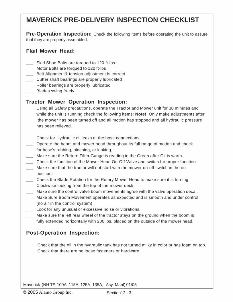
© 2005 Alamo Group Inc. Section12 - 3
Maverick (NH TS-100A, 115A, 125A, 135A, Asy. Manl) 01/05
MAVERICK PRE-DELIVERY INSPECTION CHECKLIST
Pre-Operation Inspection: Check the following items before operating the unit to assurethat they are properly assembled.
Flail Mower Head:
___ Skid Shoe Bolts are torqued to 120 ft-lbs.___ Motor Bolts are torqued to 120 ft-lbs___ Belt Alignment& tension adjustment is correct___ Cutter shaft bearings are properly lubricated___ Roller bearings are properly lubricated___ Blades swing freely
Tractor Mower Operation Inspection:Using all Safety precautions, operate the Tractor and Mower unit for 30 minutes andwhile the unit is running check the following items: Note! Only make adjustments after the mower has been turned off and all motion has stopped and all hydraulic pressurehas been relieved.
___ Check for Hydraulic oil leaks at the hose connections___ Operate the boom and mower head throughout its full range of motion and check
for hose's rubbing, pinching, or kinking.___ Make sure the Return Filter Gauge is reading in the Green after Oil is warm.___ Check the function of the Mower Head On-Off Valve and switch for proper function___ Make sure that the tractor will not start with the mower on-off switch in the on
position.___ Check the Blade Rotation for the Rotary Mower Head to make sure it is turning
Clockwise looking from the top of the mower deck.___ Make sure the control valve boom movements agree with the valve operation decal.___ Make Sure Boom Movement operates as expected and is smooth and under control
(no air in the control system)___ Look for any unusual or excessive noise or vibrations.___ Make sure the left rear wheel of the tractor stays on the ground when the boom is
fully extended horizontally with 200 lbs. placed on the outside of the mower head.
Post-Operation Inspection:
___ Check that the oil in the hydraulic tank has not turned milky in color or has foam on top.___ Check that there are no loose fasteners or hardware.

© 2005 Alamo Group Inc. Section 12 - 4Maverick (NH TS-100A, 115A, 125A, 135A, Asy. Manl) 01/05
NOTES


Maverick (NH TS-100A, 115A, 125A, 135A Asy. Man) 01/05© 2005 Alamo Group Inc.
Maverick Assembly ManualNew Holland
TS-100A, 115A, 125A, 135A2005 Edition
P/N 02982279