public safety bomb suit standard - justnet · prevention; and the office of sex offender...
TRANSCRIPT

U.S. Department of Justice
Office of Justice Programs National Institute of Justice
Public Safety Bomb Suit Standard
NIJ Standard-0117.01
September 2014
NCJ XXXXX

Public Safety Bomb Suit Standard
NATIONAL INSTITUTE OF JUSTICE
William J. Sabol
Acting Director
Chris Tillery
Office Director, Office of Science and Technology
Mark Greene
Division Director, Operational Technologies Division
Debra Stoe
Physical Scientist, Operational Technologies Division
Brian Montgomery
General Engineer, Information and Sensors Technologies Division
The National Institute of Justice is a component of the Office of Justice Programs, which also includes the Bureau of Justice Assistance; the Bureau of Justice Statistics; the Office for Victims of Crime; the Office of Juvenile Justice and Delinquency Prevention; and the Office of Sex Offender Sentencing, Monitoring, Apprehending, Registering, and Tracking (SMART).

Public Safety Bomb Suit Standard
iii
Panel of Experts
This standard was developed by a panel of practitioners, technical experts, and others with experience in standards development and conformity assessment. Panel members, their organizations, and their professional affiliations or expertise are listed in Table 1and Table 2.
Table 1. Practitioners
Type Name Organization Affiliation
Local (Retired)
Martin Hutchings, Lead
Sacramento (Calif.) Sheriff’s Department
National Bomb Squad Commanders Advisory Board (NBSCAB)
Local Tom Sharkey Metro Transit (WMATA) Police Department
NBSCAB
Local Albert Wessel Allegheny County (Pa.) Police Department
NBSCAB
Local Ursula Wiebusch Hartford (Conn.) Police Department
NBSCAB
State Christopher Ennis
Delaware State Police Department NBSCAB

Public Safety Bomb Suit Standard
iv
Table 2. Subject Matter and Technical Experts
Type Name Organization Expertise
Federal Rich Campbell U.S. Department of Justice, Bureau of Alcohol, Tobacco, Firearms and Explosives
Subject Matter Expert
Federal Marina Carboni U.S. Army Natick Soldier Research, Development and Engineering (RD&E) Center
Subject Matter Expert
Federal Fred Chan U.S. Army Natick Soldier RD&E Center
Subject Matter Expert
Federal David Colanto U.S. Army Natick Soldier RD&E Center
Subject Matter Expert
Federal Gordon Gillerman U.S. Department of Commerce, National Institute of Standards and Technology
Conformity Assessment
Federal Jerry Harkleroad U.S. Department of Justice, Federal Bureau of Investigation, Hazardous Devices School
Instructor
Federal Jeffrey Horlick (contractor)
U.S. Department of Commerce, National Institute of Standards and Technology
Conformity Assessment
Federal Everett Johnson (contractor)
U.S. Department of Homeland Security, Office of Science and Technology
Subject Matter Expert
Federal Rich McKee U.S. Department of Homeland Security, Office for Bombing Prevention
Subject Matter Expert
Federal Casandra Robinson U.S. Department of Commerce, National Institute of Standards and Technology
Standards, Conformity Assessment
Federal Mike Zielinski U.S. Army Natick Soldier RD&E Center
Subject Matter Expert
Private Pat Gleason Safety Equipment Institute Standards, Conformity Assessment
Private Richard James Lockheed Martin Corporation (NLECTC-National)
Conformity Assessment
Private Pam Kavalesky Intertek Test Laboratory Testing

Public Safety Bomb Suit Standard
v
Advisory Working Group
The work of the panel was reviewed by an Advisory Working Group (AWG) made up of senior-level representatives from stakeholder organizations and individuals with experience in standards development and conformity assessment. Organizations represented on the AWG are listed in Table 3 below.
Table 3. AWG Members
Organization
Fraternal Order of Police
International Association of Chiefs of Police
National Bomb Squad Commanders Advisory Board
National Sheriffs’ Association
National Tactical Officers Association
U.S. Department of Commerce, National Institute of Standards and Technology
U.S. Department of Defense, Technical Support Working Group
U.S. Department of Homeland Security, Science and Technology Directorate, Explosives Division
U.S. Department of Homeland Security, Science and Technology Directorate, Office of Standards
U.S. Department of Justice, Bureau of Alcohol, Tobacco, Firearms and Explosives
U.S. Department of Justice, Federal Bureau of Investigation, Hazardous Devices School

Public Safety Bomb Suit Standard
vi
Steering Committee
The Steering Committee generally directed the effort and helped to ensure coordination among relevant federal programs. The following were the members of the Steering Committee (shown in Table 4 with their respective organizations during the development of this document).
Table 4. Steering Committee Members
Member Organization Title
Gregory K. Ridgeway, Chair
U.S. Department of Justice, Office of Justice Programs, National Institute of Justice
Deputy Director
Bert Coursey U.S. Department of Homeland Security, Science and Technology Directorate, Office of Standards
Director
Mark Stolorow U.S. Department of Commerce, National Institute of Standards and Technology, Law Enforcement Standards Office
Director

Public Safety Bomb Suit Standard
vii
FOREWORD
This document is a voluntary performance standard for bomb suits for use by certified public safety bomb technicians while performing render safe procedures and disposal activities. It defines both performance requirements and the methods used to test performance. In order for a manufacturer, supplier, or other entity to claim that a particular bomb suit model satisfies this National Institute of Justice (NIJ) standard, the model must be in compliance with this standard, as determined in accordance with this document and the associated document, Public Safety
Bomb Suit Certification Program Requirements, NIJ CR-0117.01. Both this standard and the associated certification program requirements document are produced as part of the Standards and Testing Program of the U.S. Department of Justice, Office of Justice Programs, NIJ, as is a third associated document, the Public Safety Bomb Suit Selection and Application Guide, NIJ Guide–0117.01.
All requirements stated in this standard, including those that explicitly employ mandatory language (e.g., “shall”), are those necessary to satisfy this standard. Nothing in this document is intended to require or imply that commercially available bomb suits must satisfy this standard.
This document is a performance and testing standard and, therefore, provides precise and detailed test methods.
The standard is based on research from the U.S. Army Natick Soldier Research, Development and Engineering (RD&E) Center, which is documented in the report listed below. Portions of the report are used within this standard, and references to the report are cited using the letter symbol indicated below:
Symbol Cited Document
A Recommendations for a Draft Bomb Suit Standard. 2008. Natick, MA: Commander, U.S. Army Research, Development and Engineering Command, Soldier Systems Center, Natick Soldier Research, Development and Engineering Center, National Protection Center.
This standard addresses six key areas: fragmentation, impact, flame, some blast overpressure, optics, and ergonomics. Fragmentation, impact, flame, and blast overpressure are hazards against which a bomb technician needs to be protected when performing render safe procedures. Optics and ergonomics relate to a bomb technician’s ability to perform render safe procedures while wearing the bomb suit. The standard balances the protection requirements against the bomb technician’s need for mobility, clear vision, and dexterity.

Public Safety Bomb Suit Standard
viii
This standard addresses blast overpressure only in terms of bomb suit integrity; i.e., only in terms of the bomb suit’s remaining intact when subjected to an explosion. At present, research and data related to the effects of blast overpressure are limited. The following aspects of blast overpressure will not be addressed until the necessary research is complete: blast head trauma, blast thoracic injury, blunt thoracic injury, blunt lower neck trauma, other neck injury, and blast ear injury. NIJ anticipates publishing addenda or revisions to this standard when the necessary data are available and applicable requirements and test methods are defined.
Additionally, chemical, biological, radiological, and nuclear (CBRN) protection is not addressed within this standard. Research in this area is ongoing. NIJ anticipates publishing addenda or revisions when the necessary data are available and applicable requirements and test methods are defined.
Requirements for manufacturers, suppliers, or other entities seeking to demonstrate conformity with this standard are provided in a separate document, Public Safety Bomb Suit
Certification Program Requirements, NIJ CR-0117.01. Those seeking guidance concerning the selection and application of bomb suits for certified public safety bomb technicians should refer to the most recent version of the Public Safety Bomb Suit Selection and Application Guide, NIJ Guide-0117.01, which explains the standard in nontechnical language and provides guidance into selecting, procuring, using, and maintaining bomb suits.
Although agencies are advised always to require their procurements to meet or exceed the most recent and up-to-date version of this standard, this does not necessarily mean that an agency should remove bomb suits that they currently have in use from service, as a bomb suit that does not meet current standards well may be better than no bomb suit at all.
NIJ standards are subject to continued research, development and testing, review and modification as appropriate on an ongoing basis. Users of this standard are advised to consult the NIJ Standards and Testing Program webpage, accessed from www.nij.gov/standards, on a regular basis to determine whether the documents have been revised or superseded.
Technical comments and recommended revisions are welcome. Please send all written comments and suggestions to: Director, National Institute of Justice, Office of Justice Programs, U.S. Department of Justice, Washington, DC, 20531, ATTN: NIJ Standards and Testing Program.
______________
Nothing in this document is intended to create any legal or procedural rights enforceable against the United States. Moreover, nothing in this document creates any obligation for manufacturers, suppliers, public safety agencies, or others to follow or adopt this voluntary equipment standard.

Public Safety Bomb Suit Standard
ix
CONTENTS
ABBREVIATIONS, SYMBOLS, PREFIXES, AND CONVERSIONS xiii
1. SCOPE, PURPOSE, AND APPLICATION 1
1.1 Scope .......................................................................................................................................1
1.2 Purpose ....................................................................................................................................2
1.3 Application ..............................................................................................................................2
2. REFERENCES 3
2.1 Associated Publications ..........................................................................................................3
2.2 Referenced Publications..........................................................................................................3
3. DEFINITIONS 6
3.1 General ....................................................................................................................................6
3.2 Standard-Specific Definitions .................................................................................................6
4. FORM AND FIT REQUIREMENTS 12
4.1 Requirements for Bomb Suit Models ...................................................................................12
4.2 Requirements for Protective Elements of Models ................................................................13
4.3 Requirements for Accessories of Bomb Suit Models ...........................................................13
5. PERFORMANCE REQUIREMENTS 14
5.1 Acceptance Criteria for Bomb Suit Models ..........................................................................14
5.2 Ergonomics RequirementsA for Bomb Suit Models .............................................................14
5.3 Optics RequirementsA for Bomb Suit Models ......................................................................17
5.4 Flammability RequirementsA for Bomb Suit Models ...........................................................17
5.5 Electrostatic Discharge Requirements for Bomb Suit Models .............................................18
5.6 Head Protection RequirementsA for Bomb Suit Models .......................................................18
5.7 Spine Protection RequirementsA for Bomb Suit Models ......................................................19
5.8 Fragmentation Requirements for Bomb Suit Models ...........................................................19
5.9 Bomb Suit Integrity Requirements for Bomb Suit Models ..................................................20
5.10 Drag Rescue Device Requirements for Bomb Suit Models..................................................21

Public Safety Bomb Suit Standard
x
5.11 Label Durability Requirements for Bomb Suit Models ........................................................21
5.12 Optional Foot Protection Slip Resistance Requirement for Bomb Suit Models ...................21
6. TEST METHODS 22
6.1 General ..................................................................................................................................22
6.2 Donning and Quick Doffing TestA .......................................................................................23
6.3 Incapacitated Doffing TestA ..................................................................................................25
6.4 Static Field of View (FOV) Test ...........................................................................................26
6.5 Dynamic FOV – Head Motion Only TestA ...........................................................................27
6.6 Dynamic FOV – Head and Body Motion TestA ...................................................................30
6.7 Coin Recovery TestA .............................................................................................................33
6.8 Lie on Back and Stand Up TestA ..........................................................................................34
6.9 Test CourseA .........................................................................................................................34
6.10 Gross Body Mobility TestsA .................................................................................................36
6.11 Kneel and Rise TestA ............................................................................................................38
6.12 Upper Arm Abduction TestA ................................................................................................38
6.13 Upper Arm Forward Extension TestA ...................................................................................38
6.14 Upper Arm Backward Extension TestA ................................................................................39
6.15 Upper Leg Abduction TestA ..................................................................................................39
6.16 Upper Leg Flexion TestA ......................................................................................................40
6.17 Upper Leg Forward Extension TestA ....................................................................................40
6.18 Upper Leg Backward Extension TestA .................................................................................41
6.19 Fogging Assessment for Face Shields ..................................................................................41
6.20 Optics Tests ...........................................................................................................................43
6.21 Distortion TestA ....................................................................................................................44
6.22 Luminous Transmittance TestA .............................................................................................44
6.23 Haze Resistance TestA ..........................................................................................................45

Public Safety Bomb Suit Standard
xi
6.24 Refractive Power TestA .........................................................................................................45
6.25 Prismatic Deviation TestA .....................................................................................................47
6.26 Flammability TestA ...............................................................................................................47
6.27 Electrostatic Discharge Test .................................................................................................48
6.28 Head Protection TestA ...........................................................................................................49
6.29 Spine Protection TestA ..........................................................................................................52
6.30 Fragmentation TestA .............................................................................................................53
6.31 Bomb Suit Integrity TestA .....................................................................................................60
6.32 Drag Rescue Device Test ......................................................................................................62
6.33 Label Durability: Wear Test .................................................................................................63
6.34 Label Durability: Chemical Resistance Test .........................................................................63
6.35 Slip Resistance Test ..............................................................................................................64
7. LABELING AND INFORMATION 65
7.1 General Product Label Requirements for Bomb Suit Models ..............................................65
7.2 Compliance Statements on Certified Product Labels of Compliant Bomb Suit Models ......66
7.3 User Information to be Provided by the Supplier .................................................................66
7.4 Technical Data Package to be Provided by the Supplier ......................................................67
APPENDIX A. Protection Areas 68
List of Figures
Figure 1. Static FOV Axes (Oriented to the left pupil of the head form) .............................. 27
Figure 2. Method to Determine Dynamic FOV (Head Motion Only) .................................... 29
Figure 3. Method of Determining Dynamic FOV (Head and Body Motion) ......................... 32
Figure 4. Refractive Power Test Equipment and Setup .......................................................... 46
Figure 5. Protection Areas ......................................................................................................... 68
Figure 6. Body Landmarks ........................................................................................................ 70
Figure 7. Human Body Plane: (1) Frontal or Coronal, (2) Sagittal, (3) Transverse ............. 70

Public Safety Bomb Suit Standard
xii
Figure 8. Human Body Directions ............................................................................................. 70
List of Tables
Table 1. Practitioners................................................................................................................... iii
Table 2. Subject Matter and Technical Experts ....................................................................... iv
Table 3. AWG Members............................................................................................................... v
Table 4. Steering Committee Members ..................................................................................... vi
Table 5. Static FOV Requirements............................................................................................ 15
Table 6. Flammability Acceptance Criteria for Outer shell Material Specimens ................ 18
Table 7. Flammability Acceptance Criteria for Helmet Specimens ....................................... 18
Table 8. Fragmentation Performance Requirements .............................................................. 20
Table 9. Head Protection Test Matrix (DOT TP-218-5) ......................................................... 51
Table 10. Armor Types and Protection Areas for Fragmentation Testing ........................... 54
Table 11. Test Projectiles ........................................................................................................... 57
Table 12. Minimum Distance for Shot Locations .................................................................... 59
Table 13. V50 Ballistic Limit Parameters ................................................................................. 60
Table 14. Required Number of Fair Hits and Maximum Allowable Velocity Range ........... 60
Table 15. Bomb Suit Protection Area ....................................................................................... 69
List of Equations
Equation 1. Percent Difference ................................................... Error! Bookmark not defined.
Equation 2. Angle of Visual Field for Static FOV..................... Error! Bookmark not defined.
Equation 3. Occluded Angle for Dynamic FOV ....................................................................... 30
Equation 4. Back View Distance ................................................................................................ 32

Public Safety Bomb Suit Standard
xiii
ABBREVIATIONS, SYMBOLS, PREFIXES, AND CONVERSIONS
Standard-Specific Abbreviations
AASHTO American Association of State Highway and Transportation Officials
ANSI American National Standards Institute
ASTM ASTM International
CBRN Chemical/Biological/Radiological/Nuclear
DHS Department of Homeland Security
DOJ Department of Justice
DOT Department of Transportation
FBI Federal Bureau of Investigation
FOV Field of View
FSP Fragment Simulating Projectile
HS Highest Stop
IAFF International Association of Fire Fighters
IEC International Electrotechnical Commission
IED Improvised Explosive Device
ISO International Standardization Organization
ITOP International Test Operations Procedure
JIEDDO Joint Improvised Explosive Device Defeat Organization
L/D Length to diameter
LP Lowest Perforation
NFPA National Fire Protection Association
NIJ National Institute of Justice
NIOSH National Institute for Occupational Safety and Health
NIST National Institute of Standards and Technology
NLECTC National Law Enforcement and Corrections Technology Center
PPE Personal Protective Equipment
U.S. United States
VAS Visual Acuity Score
WMATA Washington Metropolitan Area Transit Authority

Public Safety Bomb Suit Standard
xiv
Commonly Used Symbols and Abbreviations
A ampere H henry nm nanometer
ac alternating current h hour No. number
AM amplitude modulation hf high frequency o.d. outside diameter
cd candela Hz hertz Ω ohm
cm centimeter i.d. inside diameter p. page
CP chemically pure in inch Pa pascal
c/s cycle per second IR infrared pe probable error
d day J joule pp. pages
dB decibel kN Kilo newton ppm parts per million
dc direct current L liter qt quart
°C degree Celsius lb pound rad radian
°F degree Fahrenheit lbf pound force rf radio frequency
diam diameter lbf⋅in pound force inch rh relative humidity
emf electromotive force lm lumen s second
eq equation ln logarithm (base e) SD standard deviation
F farad log logarithm (base 10) sec. section
fc footcandle M molar SWR standing wave ratio
fig. figure m meter uhf ultrahigh frequency
FM frequency modulation min. minute UV ultraviolet
ft foot mm millimeter V volt
ft/s foot per second mph miles per hour vhf very high frequency
g acceleration m/s meter per second W watt
g gram N newton λ wavelength
gr grain N⋅m newton meter wt weight

Public Safety Bomb Suit Standard
1
1. SCOPE, PURPOSE, AND APPLICATION
1.1 Scope
1.1.1 This document is a voluntary standard. All requirements stated in this standard, including those that explicitly employ mandatory language (e.g., “shall”) are those necessary to satisfy the standard. Nothing in this document is intended to require or imply that commercially available bomb suits must satisfy this standard. In order for a supplier or other entity to claim that a particular bomb suit model satisfies this NIJ standard, however, the model must be found to comply with this standard as determined in accordance with this document and the associated document, Public Safety Bomb Suit
Certification Program Requirements, NIJ CR-0117.01.
1.1.2 This standard specifies the minimum requirements for the form and fit, performance, testing, documentation, and labeling of bomb suits.
1.1.3 This standard specifies requirements for new, unworn bomb suits.
1.1.4 This standard addresses blast overpressure only in terms of bomb suit integrity. As of the date of the document, blast overpressure protection test measures did not provide sufficient confidence levels to recommend test methods and protective performance requirements.
1.1.5 This standard does not specify requirements for protection of wrists, hands, or ankles.
1.1.6 This standard does specify requirements for foot protection, if such protection is provided by the supplier or other entity as an optional protective element.
1.1.7 The performance requirements of this standard shall be met with all required accessories installed or integrated (see Section 7.3.3).
1.1.8 This standard does not specify requirements for protection from projectiles from firearms (e.g., bullet threats) or CBRN hazards.
1.1.9 This standard does not address search suits or reconnaissance suits (see Section 3.2.45).
1.1.10 This standard shall not be understood as addressing all of the safety concerns associated with the use of bomb suits. Users of this standard should be aware of all safety and health issues associated with the use of bomb suits. User

Public Safety Bomb Suit Standard
2
information related to these issues is provided in Public Safety Bomb Suit
Selection and Application Guide, NIJ Guide-0117.01.
1.1.11 This standard shall not be understood as addressing the safety concerns, if any, associated with the use of this standard by testing facilities.
1.1.12 No supplier or other entity shall claim compliance with only selected portions of this standard. The bomb suit model shall meet all applicable stated requirements of this standard.
1.1.13 Nothing herein shall be understood to restrict any supplier or other entity from exceeding the requirements of this standard.
1.1.14 As appropriate (e.g., for models that employ materials or forms of construction that were not anticipated when this standard was developed or are not addressed by this standard), NIJ may modify the test methods of the standard or establish new ones.
1.2 Purpose
1.2.1 The purpose of this NIJ voluntary standard is to specify minimum requirements for bomb suits worn by bomb technicians conducting render safe procedures, analysis, and disposal activities, and test methods for assessing that the performance requirements are met.
1.2.1.1 The purpose of the test methods in this standard is to assess performance and should not be understood to specify performance levels for all situations and hazards to which bomb technicians may be exposed.
1.3 Application
1.3.1 This standard provides for one level of protection.

Public Safety Bomb Suit Standard
3
2. REFERENCES
2.1 Associated Publications
The following document is a companion publication to NIJ Standard-0117.01 and NIJ CR-0117.01.
NIJ Guide-0117.01, Public Safety Bomb Suit Selection and Application Guide. Washington, DC: National Institute of Justice, U.S. Department of Justice.
2.2 Referenced Publications
The following references form a basis for and provide support for the requirements and procedures described in this standard. For dated references, only the edition cited applies. For undated references, the latest edition of the referenced document applies, including any amendments.
2.2.1 American National Standards Institute Publications
ANSI/ASSE Z87.1-2003, Occupational and Educational Personal Eye and
Face Protection Devices. 2003. Washington, DC: American National Standards Institute.
2.2.2 ASTM International Publications
ASTM Standard D1003-00, 2000, “Standard Test Method for Haze and Luminous Transmittance of Transparent Plastics,” ASTM International, West Conshohocken, PA, 2000, DOI: 10.1520/D1003-00, www.astm.org.
ASTM Standard D6413-99, 1999, “Standard Test Method for Flame Resistance of Textiles (Vertical Test),” ASTM International, West Conshohocken, PA, 1999, DOI: 10.1520/D6413-99, www.astm.org.
ASTM Standard F1587-12a, 2012, “Standard Specification for Head and Face Protective Equipment for Ice Hockey Goaltenders,” ASTM International, West Conshohocken, PA, 2012, DOI: 10.1520/F1587-12A, www.astm.org.
ASTM Standard F2220, 2002, “Standard Specification for Headforms,” ASTM International, West Conshohocken, PA, 2002, DOI: 10.1520/F2220-02, www.astm.org.

Public Safety Bomb Suit Standard
4
ASTM Standard F489, 1996, “Standard Test Method for Static Coefficient of Friction of Shoe Sole and Heel Material as Measured by the James Machine,” ASTM International, West Conshohocken, PA, 1996, DOI: 10.1520/F0489-96, www.astm.org.
2.2.3 Canadian Standards Association Publications
CAN/CSA Z617-06, Personal Protective Equipment (PPE) for Blunt Trauma. 2006. Mississauga, Ontario: Canadian Standards Association.
2.2.4 Electrostatic Discharge Association Publications
STM 2.1-1997, Electrostatic Discharge Association Standard Test Method for
the Protection of Electrostatic Discharge Susceptible Items – Garments. 1997. Rome, NY: Electrostatic Discharge Association.
2.2.5 ISO/IEC Publications
ISO/IEC Guide 65:1997. General Requirements for Bodies Operating Product
Certification Systems.
IEC 60825-1: 2007. Safety of laser products - Part 1: Equipment
classification and requirements.
2.2.6 National Fire Protection Association (NFPA) Publications
NFPA 1971, Standard on Protective Ensembles for Structural Fire Fighting
and Proximity Fire Fighting. 2007. Quincy, MA: National Fire Protection Association.
2.2.7 U.S. Government Publications
Washer, E.; Gardner, I. C. NBS resolution test chart 1952, presented in Method for determining the resolving power of photographic lenses. National Bureau of Standards (U.S.) Spec. Publ. 374; 1973 June.
NIJ CR-0117.01, Public Safety Bomb Suit Certification Program
Requirements. Washington, DC: National Institute of Justice, U.S. Department of Justice.
NIJ Standard-0104.02, NIJ Standard for Riot Helmets and Face Shields. Washington, DC: U.S. Department of Justice, National Institute of Justice.

Public Safety Bomb Suit Standard
5
NIJ Standard-0116.00, CBRN Protective Ensemble Standard for Law
Enforcement. Washington, DC: U.S. Department of Justice, National Institute of Justice.
NIOSH CET-APRS-STP-CBRN-0314, Revision 1.1 – Determination of Lens
Fogging on Full-Facepiece Chemical Biological Radiological and Nuclear
(CBRN) Air-Purifying Respirators Standard Test Procedure, 2005.Washington, DC: National Institute of Occupational Safety and Health.
TP-218-06, Laboratory Test Procedure for Motor Vehicle Safety Standard
FMVSS No. 218 — Motorcycle Helmets. 2006. Washington, DC: U.S. Department of Transportation.
2.2.8 U.S. Military Publications
International Test Operations Procedure (ITOP) 4-2-805 – Projectile Velocity
and Time of Flight Measurements. 1999. Washington, DC: U.S. Department of Defense.
MIL-STD-662F – V50 Ballistic Test for Armor. 1997. Washington, DC: U.S. Department of Defense.
MIL-P-46593A (ORD) — Projectile Calibers .22, .30, .50 and 20 mm
Fragment-Simulating. 1962. Washington, DC: U.S. Department of Defense.
MIL-DTL-43511D — Detail Specification, Face Shields, Flyer’s Helmet,
Polycarbonate. 2006. Washington, DC: U.S. Department of Defense.
Recommendations for a Draft Bomb Suit Standard. 2008. Natick, MA: Commander, U.S. Army Research, Development and Engineering Command, Soldier Systems Center, Natick Soldier Research, Development and Engineering Center, National Protection Center.
Public Safety Bomb Suit Standard
6
3. DEFINITIONS
3.1 General
3.1.1 The definitions contained in this chapter shall apply to these terms as used in this standard. Where terms are not defined in this chapter or within another chapter, they shall be defined using their ordinarily accepted meanings, unless the context unmistakably indicates otherwise.
3.2 Standard-Specific Definitions
3.2.1 Abduction: Movement of a body part away from the medial plane of the body.
3.2.2 Accessories: Any supplier-recommended or aftermarket items that can be attached to the bomb suit.
3.2.2.1 Optional accessories: Items available for use with the bomb suit but not necessary for meeting the requirements of this standard.
3.2.2.2 Required accessories: Items provided with a bomb suit and necessary for meeting the requirements of this standard.
3.2.3 Anchor point: A mechanism intended to prevent unintentional detachment of protective elements.
3.2.4 Blast overpressure: Air pressure that is significantly greater than the surrounding atmospheric pressure, as a result of the shock wave from an explosion.
3.2.5 Bomb suit: An ensemble designed to provide limited protection for the head, face, neck, thorax/abdomen, pelvis, arms, and legs from the hazards associated with the detonation of an explosive device.
3.2.6 Bomb technicians: Qualified public safety personnel who perform render safe procedures, analysis, and disposal activities for hazardous explosive devices.
3.2.7 Care: Cleaning, decontamination, and storage of a product.
3.2.8 Certified product: Any unit of a compliant model.

Public Safety Bomb Suit Standard
7
3.2.9 Chemical, biological, radiological and nuclear (CBRN) hazards: Chemical warfare agents, toxic industrial chemicals, biologically derived toxins or pathogens and radiological particulate hazards that may inflict bodily harm, incapacitation, or death (NIJ Standard-0116.00, 2010).
3.2.10 CBRN protective accessory: A type of optional accessory intended to provide protection against CBRN hazards and that may not meet the requirements of this standard.
3.2.11 Compliant: The condition of a bomb suit model’s meeting or exceeding all applicable requirements of this standard as determined pursuant and subject to NIJ CR-0117.
3.2.12 Component: Any material, part, or subassembly used in construction of the bomb suit or protective element.
3.2.13 Cosmetic damage: Discoloration, fraying, singeing, ripping, tearing, etc., of outer fabric layers and items such as straps or closures.
3.2.14 Disposal: The safe elimination of potentially hazardous materials.
3.2.15 Doff: To remove from a wearer (as in a garment).
3.2.15.1 Incapacitated doff: The removal of a bomb suit from a wearer who is incapable of assisting in bomb suit removal.
3.2.15.2 Quick doff: The quick removal of a bomb suit by the wearer.
3.2.16 Don: To put on a wearer (as in a garment).
3.2.17 Drag rescue device: A reinforced handle on the exterior of a bomb suit for the purpose of moving an incapacitated wearer.
3.2.18 Duty footwear: A shoe or boot worn by a bomb technician that is not designed to provide protection from the hazards associated with the detonation of an explosive device.
3.2.19 Electrostatic discharge: A rapid transfer of electrically charged particles between objects that has the potential to initiate an explosive charge or ignite combustible materials.

Public Safety Bomb Suit Standard
8
3.2.20 Face shield: The protective element that is designed to protect the wearer’s face from the hazards associated with the detonation of an explosive device.
3.2.21 Fair hit: The impact of a projectile on an armor specimen that meets the shot-spacing requirements of Section 6.30.3.5 and the yaw requirements of Section 6.30.3.3.
3.2.22 Field of view (FOV): The area that a bomb suit permits its wearer to see when looking through its face shield.
3.2.23 Flammability: A material’s capacity to support combustion.
3.2.24 Foot protection: An optional protective element that is designed to protect the foot, from the top to the sole.
3.2.25 Fragment simulating projectile (FSP): A standardized cylindrical steel projectile designed to emulate the general ballistic performance of irregularly shaped metallic fragments associated with an explosive device.
3.2.26 Fragmentation test: Laboratory ballistic test procedure for determining the protection level of target materials against an FSP.
3.2.27 Goniometer: A device for measuring angular position.
3.2.28 Head protection: The protective element that is designed to protect the wearer’s head, not including the face.
3.2.29 Helmet: Synonymous with Head Protection.
3.2.30 Impact attenuation: Capacity of personal protective equipment to reduce the severity of contact by absorbing and/or distributing energy.
3.2.31 Maintenance: Inspection, repair, and retirement of a product.
3.2.32 Manufacturer: A commercial enterprise engaged in fabricating a product.
3.2.33 Model: The manufacturer’s design, with unique specifications and characteristics, of a particular item.
3.2.34 Objective: The desired target value for a performance requirement.

Public Safety Bomb Suit Standard
9
3.2.35 Optics test: Procedure that evaluates essential optical properties of the face shield.
3.2.36 Outer shell materials: The exterior layer of material of the bomb suit without the helmet, excluding reinforcements, pouches, fasteners, zippers, closures, binding, or similar items attached to the shell.
3.2.37 Perforation: Any projectile impact that creates a crack or hole passing through something. The term perforation includes complete penetration, as that term is used in other standards.
3.2.38 Personal protective equipment (PPE): Any item providing protection to the wearer against a hazard.
3.2.39 Product: One unit of a particular model.
3.2.40 Protection areas: The following portions of the body that a bomb suit is designed to protect from the hazards associated with the detonation of an explosive device: (1) head, (2) face, (3) neck, (4) thorax/abdomen, (5) pelvis, (6) arms, and (7) legs. Many protection areas have different performance requirements for the front, sides, and rear of the body. Diagrams, sketches, and detailed descriptions are provided in Appendix A. Hands, wrists, and ankles are not protection areas.
3.2.40.1 Head: The area from the top of the skull to the chin in the front and to the base of skull in the rear, excluding the face.
3.2.40.2 Face: The surface of the front of the head, including enough area to meet the vision requirements of this standard.
3.2.40.3 Neck: The part of the body joining the head to the trunk, from the chin to the top of the chest in front, and from the bottom of the skull to the shoulder line in back.
• Neck - Front Lateral
• Neck - Front Medial
• Neck - Rear
3.2.40.4 Thorax/Abdomen: The trunk of the body from the base of the neck to the navel line, in the front and back, excluding the arms.
• Thorax/Abdomen - Front Lateral (left and right)
• Thorax/Abdomen – Front Medial
• Thorax/Abdomen - Rear

Public Safety Bomb Suit Standard
10
3.2.40.5 Pelvis: The trunk of the body below the navel line, in the front and back, excluding the legs.
• Pelvis – Front Lateral
• Pelvis – Front Medial
• Pelvis - Rear
3.2.40.6 Arms: The upper limbs of the body, from the shoulder crease/armpit to the wrist crease.
3.2.40.7 Legs: The lower limbs of the body, from the crotch to the ankle crease.
• Legs - Lower Front: From the bottom of the kneecap to the ankle crease in front of the coronal plane (refer to Figure 6).
• Legs - Lower Rear: From the bottom of the kneecap to the ankle crease behind the coronal plane (refer to Figure 6).
• Legs – Upper: From the crotch to the bottom of the kneecap.
3.2.41 Protective elements: The parts of the bomb suit that provide protection to the areas of the wearer’s body described in Section 3.2.40.
3.2.42 Render safe procedure: Actions taken to mitigate a bomb threat. Such actions may include deploying explosive or mechanical means to separate essential parts of the hazardous device.
3.2.43 Retention system: Hardware assembly used to retain a helmet in position on the head during use.
3.2.44 Sample: A bomb suit, protective element, or component that is to be subjected to conditioning procedures as specified in this standard in preparation for subsequent testing. A sample is to be representative of a model (or a model protective element or a model component, as applicable).
3.2.44.1 Facsimile sample: A type of sample that is not taken from an actual bomb suit, protective element, or component, but that is prepared with materials and construction identical to an actual bomb suit, protective element, or component. Each facsimile sample shall include any protective element(s) and any associated component layer(s).
3.2.45 Search suit or reconnaissance suit: A type of PPE intended to provide protection to a bomb technician during a search for explosive devices but not intended to provide the level of protection offered by the bomb suit addressed in this standard.

Public Safety Bomb Suit Standard
11
3.2.46 Shall: Indicates a mandatory requirement for the purposes of this voluntary standard.
3.2.47 Should: Indicates a recommendation that is advised but not required for the purposes of this voluntary standard.
3.2.48 Specimen: (1) A piece or portion of a sample to be tested (following conditioning as specified in this standard) that is representative of the whole sample, or (2) A complete sample to be tested (following conditioning as specified in this standard). (See 3.2.44, Sample.)
3.2.49 Spine protection: The protective element that is designed to protect the thoracolumbar region.
3.2.50 Spine protector: Synonymous with spine protection.
3.2.51 Stop: Any fair hit of a projectile on a sample or specimen that does not result in a perforation. The term stop includes partial penetration, as that term is used in other standards.
3.2.52 Supplier: The party that is responsible for ensuring that products meet and, if applicable, continue to meet, the requirements on which the certification is based (ISO/IEC Guide 65, 3.1).
3.2.53 Test subject: An individual who dons a bomb suit and performs specified activities for testing purposes under this standard. The test subject shall hold a current Federal Bureau of Investigation Hazardous Device School bomb technician certification.
3.2.54 Test surrogate: Device used as a human substitute in laboratory procedures.
3.2.55 Threshold: A minimum acceptable value for a performance requirement.
3.2.56 V50 ballistic limit: For a given projectile type, an estimate of the velocity at which the projectile is expected to perforate an armor specimen 50% of the time. The ballistic limit is typically denoted as the V50 or V50 value.
3.2.57 Walking surface: The portion of foot protection that contacts the ground during normal walking, including the ball and/or heel where appropriate.
3.2.58 Yaw: The angular deviation of the longitudinal axis of the projectile from its line of flight, measured as close to the target as practical.

Public Safety Bomb Suit Standard
12
4. FORM AND FIT REQUIREMENTS
To be tested under the performance requirements of this standard, bomb suit models shall satisfy the requirements of this chapter.
4.1 Requirements for Bomb Suit Models
4.1.1 Bomb suits shall meet or exceed the applicable requirements specified in this section.
4.1.2 Bomb suits shall be designed to protect at least the wearer’s head, face, neck, thorax/abdomen, pelvis, arms, and legs.
4.1.3 The bomb suit design shall be such that body movement of the user (e.g., reaching and bending) does not result in any protection areas of the body becoming unprotected.
4.1.4 The bomb suit arm protection shall incorporate a means of tightening the sleeve at the wrist when on the wearer.
4.1.5 Bomb suits shall be available in at least three distinct sizes.
4.1.6 Bomb suits, including all required accessories, shall have a maximum weight not exceeding the limits specified in Section 4.1.6.1. This weight does not include optional accessories.
4.1.6.1 If three bomb suits are necessary to meet the requirement for three distinct sizes as specified in Section 4.1.5, the maximum weight for each size shall be as follows: 68.0 lb for smallest size, 76.0 lb for midrange size, and 85.0 lb for largest size. If one bomb suit can be adjusted to meet the requirement for three distinct sizes, then the properly adjusted bomb suit shall meet the weight requirements for each corresponding size.
4.1.7 Bomb suits shall incorporate at least two drag rescue devices, one located on each shoulder.
4.1.8 Bomb suits shall have a grounding strap, extending from at least one leg of the bomb suit, for the purpose of preventing electrostatic discharge between the bomb technician and the explosive device.
Public Safety Bomb Suit Standard
13
4.1.8.1 One end of the grounding strap shall have a means for being fastened to the bomb suit and the wearer’s leg or ankle. The opposite end of the grounding strap shall have a means for being fastened to either the optional foot protection or the bomb suit wearer’s duty footwear, such that the strap discharges any electrical charge to ground.
4.1.9 Bomb suits shall have a nondestructive means for incapacitated doffing, such that the bomb suit meets the requirements of Section 5.2.3 and is functional following incapacitated doffing.
4.2 Requirements for Protective Elements of Models
4.2.1 The face shield shall have no blind spot in or partitioning of the field of view.
4.2.2 The face shield may be attached to the helmet using various means of attachment. A face shield that is hinged and flips up shall have a locking mechanism to keep the face shield in the upright position until the wearer disengages the locking mechanism.
4.2.3 The helmet shall have a means to achieve a snug, comfortable fit using an adjustable fitting system and/or various helmet sizes.
4.2.4 Spine protection shall be designed to protect the wearer’s spine, from at least the top of the T1 vertebra to at least the bottom of the L5 lumbar vertebra, and shall have a minimum width of 20.3 cm (8 inches).
4.3 Requirements for Accessories of Bomb Suit Models
4.3.1 The supplier shall provide written documentation identifying required and optional accessories.
4.3.2 No optional accessories shall be required to meet the form and fit and performance requirements of this standard.
4.3.3 No required accessories shall interfere with the function of the bomb suit. Where bomb suits are provided with required accessories that are attached to or integrated with the bomb suit, the bomb suit with required accessories installed shall meet all of the form and fit and performance requirements of this standard.

Public Safety Bomb Suit Standard
14
5. PERFORMANCE REQUIREMENTS
5.1 Acceptance Criteria for Bomb Suit Models
5.1.1 Bomb suit models shall meet or exceed all applicable performance requirements specified in the categories below:
• Ergonomics (See Section 5.2).
• Optics (See Section 5.3).
• Flammability (See Section 5.4).
• Electrostatic discharge (See Section 5.5).
• Head protection (See Section 5.6).
• Spine protection (See Section 5.7).
• Fragmentation (See Section 5.8).
• Blast integrity (See Section 5.9).
• Drag rescue (See Section 5.10).
• Label durability (See Section 5.11).
• Optional foot protection slip resistance (See Section 5.12).
5.1.2 No specific test sequence is required, but if the supplier opts to use the same helmet samples for tests in Sections 6.26 and 6.28 (as allowed in Section 6.26.1.2), the Section 6.28 testing shall occur first.
5.1.3 Unless the performance requirement is specifically stated as an average result, failure of any individual specimen result to meet the performance requirement shall constitute failing performance.
5.2 Ergonomics RequirementsA for Bomb Suit Models
5.2.1 Bomb suits, including all required accessories, shall be tested for donning time as specified in Section 6.2, Donning and Quick Doffing Test, and each bomb suit size shall have an average assisted donning time of less than 5 minutes.
5.2.2 Bomb suits, including all required accessories, shall be tested for quick doffing time as specified in Section 6.2, Donning and Quick Doffing Test, and each bomb suit size shall have an average quick doffing time of less than 2 minute.

Public Safety Bomb Suit Standard
15
5.2.3 Bomb suits, including all required accessories, shall be tested for incapacitated doffing as specified in Section 6.3, Incapacitated Doffing Test, and for each trial for incapacitated doffing, the test assistant shall remove the bomb suit in less than 1 minute.
5.2.4 Bomb suits, including all required accessories, shall be tested for static field of view as specified in Section 6.4, Static Field of View Test, and the visual field shall not be less than the values provided in Table 5 below:
Table 5. Static FOV Requirements
Measurement Angle
(degrees)
Superior 21
Super-Nasal, Super-Temporal 29
Nasal, Temporal 44
Infero-Nasal, Infero-Temporal 34
Inferior 40
5.2.5 Bomb suits, including all required accessories, shall be tested for dynamic FOV, head rotation as specified in Section 6.5, Dynamic FOV Test — Head
Motion Only, and shall have an average head rotation value for all trials (of a particular size of a specific bomb suit) of no greater than 22.5 degrees.
5.2.6 Bomb suits, including all required accessories, shall be tested for dynamic FOV and head and body motion as specified in Section 6.6, Dynamic FOV
Test – Head and Body Motion, and shall have an average value for all trials (for a particular size of a specific bomb suit) of no less than 30 cm (12 inches) in the backward direction.
5.2.6.1 Bomb suits, including all required accessories, shall be tested as specified in Section 6.7, Coin Recovery Test, and successful completion of the task is required. After locating the coin, it is not required that the subject maintain visual contact with the coin through the face shield throughout the exercise. Each test subject is required to pass, and failure of one subject to complete the task shall result in a failure for the bomb suit.
5.2.6.2 Bomb suits, including all required accessories, shall be tested as specified in Section 6.8, Lie on Back and Stand Up Test, and each subject shall pass all attempts to complete the task. No protective element shall shift in a way that reduces the protection defined in this document.

Public Safety Bomb Suit Standard
16
5.2.7 Bomb suits, including all required accessories, shall be tested as specified in Section 6.9, Test Course, and the test subject shall successfully complete the course. During navigation of the course, no protective element or component shall shift in a way that reduces the protection or functionality of the bomb suit.
5.2.8 Gross Body Mobility RequirementsA
5.2.8.1 All gross body mobility tests referenced below shall begin with the guidelines specified in Section 6.10, Gross Body Mobility Tests.
5.2.8.2 Bomb suits, including all required accessories, shall be tested for gross body mobility as specified in Section 6.11, Kneel and Rise Test, and the test subject shall be able to rise from the kneeling position without any human assistance and without grasping any object or wall for support.
5.2.8.3 Bomb suits, including all required accessories, shall be tested for gross body mobility as specified in Section 6.12, Upper Arm Abduction Test.
5.2.8.4 Bomb suits, including all required accessories, shall be tested for gross body mobility as specified in Section 6.13, Upper Arm Forward Extension Test.
5.2.8.5 Bomb suits, including all required accessories, shall be tested for gross body mobility as specified in Section 6.14, Upper Arm Backward Extension Test.
5.2.8.6 Bomb suits, including all required accessories, shall be tested for gross body mobility as specified in Section 6.15, Upper Leg Abduction Test.
5.2.8.7 Bomb suits, including all required accessories, shall be tested for gross body mobility as specified in Section 6.16, Upper Leg Flexion Test.
5.2.8.8 Bomb suits, including all required accessories, shall be tested for gross body mobility as specified in Section 6.17, Upper Leg Forward Extension Test.
5.2.8.9 Bomb suits, including all required accessories, shall be tested for gross body mobility as specified in Section 6.18, Upper Leg Backward Extension Test.
5.2.9 Bomb suits, including all required accessories, shall be tested as specified in Section 6.19, Fogging Assessment, and the average Visual Acuity Score (VAS) shall be ≥ 75 points (NIOSH Procedure No. CET-APRS-STP-CBRN-0314, Section 6.1).

Public Safety Bomb Suit Standard
17
5.3 Optics RequirementsA for Bomb Suit Models
5.3.1 Optics requirements for face shields shall be assessed by performing the tests specified in Section 6.20.
5.3.2 Face shields, including any supplier-recommended appliqués, shall be tested as specified in Section 6.21, Distortion Test, and line patterns shall not deviate greater than one line width within the critical vision areas as shown in MIL-DTL-43511D, Figure 2.
5.3.3 Face shields, including any supplier-recommended appliqués, shall be tested as specified in Section 6.22, Luminous Transmittance Test, and the luminous transmittance shall not be less than 65% photopic within the critical vision area as described in MIL-DTL-43511D, Section 3.4.
5.3.4 Face shields, including any supplier-recommended appliqués, shall be tested as specified in Section 6.23, Haze Resistance Test, and shall have no more than 4.0% haze within the critical vision areas as described in MIL-DTL-43511D, Section 3.4.
5.3.5 Face shields, including any supplier-recommended appliqués, shall be tested as specified in Section 6.24, Refractive Power Test, and the refractive power shall not exceed ± 0.5 diopters within the critical vision areas as described in MIL-DTL-43511D, Section 3.4.
5.3.6 Face shields, including any supplier-recommended appliqués, shall be tested as specified in Section 6.25, Prismatic Deviation Test. The vertical prismatic deviation for the right eye or left eye shall be no more than 0.25 prism diopters. The vertical prismatic imbalance shall not exceed 0.13 prism diopters along the primary (straight ahead) line of sight. The horizontal prismatic imbalance shall not exceed 3.0 prism diopters BASE OUT or 0.1 prism diopters BASE IN for the primary (straight ahead) line of sight.
5.4 Flammability RequirementsA for Bomb Suit Models
5.4.1 Outer shell materials and helmets shall be tested as specified in Section 6.26, Flammability Test.
5.4.2 Flammability acceptance criteria for outer shell material specimens are specified in Table 6.

Public Safety Bomb Suit Standard
18
Table 6. Flammability Acceptance Criteria for Outer Shell Material Specimens
Measurement Threshold
Char length 89 mm (3.5 inches)
Afterflame 2.0 seconds
Afterglow 25.0 seconds
Flaming melt drip Not allowed
5.4.3 Flammability acceptance criteria for helmet specimens are specified in Table 7.
Table 7. Flammability Acceptance Criteria for Helmet Specimens
Measurement Threshold
Afterflame 15.0 seconds
Afterglow 25.0 seconds
Flaming melt drip Not allowed
Visor Remain Attached
5.5 Electrostatic Discharge Requirements for Bomb Suit Models
5.5.1 Bomb suits, including all required accessories, but excluding the helmet, shall be tested as specified in Section 6.27, Electrostatic Discharge Test. The grounding strap shall have a resistance of greater than 1 MΩ ± 5%.
5.5.2 The grounding strap shall be tested for unintentional detachment during the test specified in Section 5.2.7 and shall not detach or disconnect during the test.
5.6 Head Protection RequirementsA for Bomb Suit Models
5.6.1 Head protection requirements are specified in terms of impact attenuation, perforation resistance and retention system. Head protection shall be tested as specified in Section 6.28, Head Protection Test.
5.6.2 Head protection (without face shields, if detachable) shall be tested for impact attenuation. The following acceleration threshold values for impact attenuation shall not be exceeded:
a) 290 g.

Public Safety Bomb Suit Standard
19
b) 2.0 ms dwell time above 200 g.
c) 4.0 ms dwell time above 150 g.
5.6.3 Head protection (without face shields, if detachable) shall be tested for perforation resistance. As described in clause 12.7.4 of DOT TP-218-06, there shall be no contact between the striker and the surface of the headform at any point above the test line.
5.6.4 Head protection (without face shields, if detachable) shall be tested for the retention system. As described in clause 12.8.3 of DOT TP-218-06, none of the following shall occur:
a) Any separation of the retention system or its components, including the helmet shell, is observed; and/or
b) The retention system moves more than 2.5 cm (1 inch), measured between preliminary and full test load positions.
5.7 Spine Protection RequirementsA for Bomb Suit Models
5.7.1 Spine protection shall be tested as specified in Section 6.29, Spine Protection
Test, and the impact attenuation shall not exceed the maximum force value of 4kN.
5.8 Fragmentation Requirements for Bomb Suit Models
5.8.1 Samples representative of all armor types and corresponding protection areas shall be tested as specified in Section 6.30, Fragmentation Test. The bomb suit shall meet the armor type fragmentation requirements specified in Table 8 for each protection area.
5.8.2 For each test projectile and armor type, the calculated V50 ballistic limit of each test sample shall meet or exceed the appropriate value specified in Table 8, subject to the following exception:
• If the estimated V50 from a single ballistic limit test on a given protection area with a particular projectile is less than the requirement specified in Table 8, but not more than 25 m/s below the requirement, the fragmentation requirement for that protection area and projectile nonetheless shall be considered to have been met if the arithmetic mean of the three V50 ballistic limit values is greater than or equal to the requirement specified in Table 8.

Public Safety Bomb Suit Standard
20
5.8.3 If optional foot protection is provided, the calculated V50 ballistic limit of each test sample shall meet or exceed 450 m/s (1,476 ft/s) for the .22 cal (17 gr) FSP test projectile.
Table 8. Fragmentation Performance Requirements
Armor
Type
Test
Projectile
Projectile Mass V50 Ballistic
Limit
A .30 cal FSP
2.9 g (44gr)
1,100 m/s (3,609 ft/s)
.50 cal FSP
13.4 g (207 gr)
750 m/s (2,461 ft/s)
B .22 cal FSP
1.1 g (17 gr)
775 m/s (2,542 ft/s)
C .22 cal FSP
1.1 g (17 gr)
625 m/s (2,051 ft/s)
.30 cal FSP
2.9 g (44 gr)
525 m/s (1,722 ft/s)
D .22 cal FSP
1.1 g (17 gr)
625 m/s (2,051 ft/s)
.30 cal FSP
2.9 g (44 gr)
550 m/s (1,804 ft/s)
E .22 cal FSP
1.1 g (17 gr)
550 m/s (1,804 ft/s)
.30 cal FSP
2.9 g (44 gr)
525 m/s (1,722 ft/s)
F .22 cal FSP
1.1 g (17 gr)
525 m/s (1,722 ft/s)
.30 cal FSP
2.9 g (44 gr)
500 m/s (1,640 ft/s)
G .22 cal FSP
1.1 g (17 gr)
350 m/s (1,148 ft/s)
.30 cal FSP
2.9 g (44 gr)
300 m/s (984 ft/s)
5.9 Bomb Suit Integrity Requirements for Bomb Suit Models
5.9.1.1 Bomb suits shall be tested for integrity as specified in Section 6.31, Bomb Suit
Integrity Test. The level of bomb suit integrity shall be considered acceptable if all of the following criteria are met:
• All protective elements must remain secured on the test surrogate as follows:
o The helmet shall remain in the donned position. The helmet shall show no evidence of collapse.
o The face shield shall remain attached to the helmet in the donned position. Cosmetic damage is permissible as long as such damage does not compromise the innermost surface. The innermost surface shall

Public Safety Bomb Suit Standard
21
show no evidence of any hole, cracking, spalling, or shattering. The face shield shall remain attached to its frame.
o Protective elements covering the neck, thorax/abdomen, and pelvis protection areas shall remain attached to the bomb suit in the donned position. These protective elements shall maintain shape integrity and show no evidence of collapse.
o Protective elements shall remain attached to the bomb suit at the anchor points.
• Cosmetic damage is permissible, as long as such damage does not compromise the integrity of the protective layers within the bomb suit. Rips or holes in the outer fabric ballistic protection layer are permissible, as long as they do not perforate the innermost fabric ballistic protection layer.
• No gaps that expose the surface of the test surrogate are allowed.
5.10 Drag Rescue Device Requirements for Bomb Suit Models
5.10.1 Each drag rescue device shall be tested independently, as specified in Section 6.32, Drag Rescue Device Test, and the test assistant shall be able to drag the test surrogate in the bomb suit in a straight line using each drag rescue device for the distance specified in NFPA 1971 (2007), Section 8.59.5.10.
5.11 Label Durability Requirements for Bomb Suit Models
5.11.1 The label shall be tested for label durability as specified in Section 6.33, Label
Durability: Wear Test, and the label markings shall meet the legibility requirements specified in NFPA 1971 (2007), Section 8.42.4.2.2.
5.11.2 The label shall be tested for label durability as specified in Section 6.34, Label
Durability: Chemical Resistance Test, and the label markings shall meet the legibility requirements specified in NFPA 1971 (2007), Section 8.42.4.2.2.
5.12 Optional Foot Protection Slip Resistance Requirement for Bomb Suit
Models
5.12.1 Foot protection shall be tested as specified in Section 6.35, Slip Resistance
Test, and shall have a static coefficient of friction of 0.60 or greater under dry conditions.

Public Safety Bomb Suit Standard
22
6. TEST METHODS
6.1 General
6.1.1 Acceptance criteria shall be as stated in Chapter 5, Performance Requirements.
6.1.2 All samples and facsimile samples shall be provided for testing by the supplier.
6.1.3 Any test involving a test subject that results in failure shall be repeated with the subject not wearing the bomb suit, so as to determine if the subject is capable of performing the test. If the subject cannot perform the test successfully while not wearing the bomb suit, those failing test results shall be disregarded, and the test shall be repeated with another subject.
6.1.4 For any viewing or visibility tests involving a test subject (Sections 6.5, 6.6, and 6.19), the test subject shall have 20/40 vision or better, either unaided or with the use of contact lenses.
6.1.5 For all tests requiring a test subject to perform tasks, a warm-up period is required immediately prior to the first test. Warm-up activities will consist of marching in place for 1 minute, 15 deep-knee bends, swinging the arms (forward and backward) for 30 seconds in each direction, and 30 jumping jacks followed by a 10-minute rest period.
6.1.6 The height and weight of the test subject(s) for each test shall be recorded and reported.
6.1.7 All test results and observations shall be recorded and reported.
6.1.8 Unless a tolerance is specified within the test methods, values for measurements (e.g., dimensions, distance, weight, and angular displacement) shall be considered to be approximate. In these cases, where possible, the tolerance should be considered to be within ± 1.0%.
6.1.9 Unless otherwise specified within the test methods, the temperature and
humidity conditions during testing shall be 21 ± 2.9˚C (70 ± 5˚F) and 50 ± 20% rh.

Public Safety Bomb Suit Standard
23
6.1.10 Unless the context unmistakably indicates otherwise, the duration specified in this chapter for any procedure (e.g., “12 hours”) shall be understood to run consecutively (e.g., “12 consecutive hours”).
6.1.11 Unless the context unmistakably indicates otherwise, an indication that an action is to “follow” something else or otherwise is to occur after something else should be understood to mean that the subsequent action should occur immediately after the preceding event.
6.2 Donning and Quick Doffing TestA
6.2.1 Samples
6.2.1.1 One sample each of the smallest and largest size bomb suit offered by the supplier shall be submitted for testing.
6.2.1.2 Bomb suits shall be submitted for testing with all required accessories.
6.2.1.3 Test samples shall be exposed to 21 ± 2.9˚C (70 ± 5˚F) and 50 ± 20% rh for a minimum of 12 hours before testing.
6.2.2 Test Subjects and Equipment
6.2.2.1 One subject is required to test each bomb suit size. The test subjects selected for each bomb suit size being tested shall be appropriate based on the supplier’s sizing chart.
6.2.2.2 An armless chair is required.
6.2.2.3 A timer is required.
6.2.3 Procedure
6.2.3.1 The test subject initially shall wear loose-fitting, nonrestrictive clothing.
6.2.3.2 The subject shall review and practice the supplier’s donning, doffing, and adjustment procedures prior to the start of the test.
6.2.3.3 The donning test shall begin with the subject sitting in an armless chair with the bomb suit in front of the subject on the floor and out of the package.

Public Safety Bomb Suit Standard
24
6.2.3.4 The subject may be assisted by a single donning assistant, and the chair may be used during the process.
6.2.3.5 At a cue from the test administrator, the subject shall rise from the chair and begin donning the bomb suit in accordance with the supplier’s instructions. Timing shall start when the subject receives the cue from the test administrator to begin donning the bomb suit.
6.2.3.6 After completely donning the bomb suit, the subject shall cue the test administrator.
6.2.3.7 Timing shall cease at the cue from the subject. The administrator shall record the donning time.
6.2.3.8 The quick doffing test shall begin with the subject wearing the properly donned bomb suit and sitting in an armless chair.
6.2.3.9 At a cue from the test administrator, the subject shall rise from the chair and begin doffing the bomb suit in accordance with the supplier’s instructions. Timing shall start when the subject receives the cue from the test administrator to begin doffing the bomb suit.
6.2.3.10 The subject shall doff the bomb suit unassisted. The chair may be used during the process.
6.2.3.11 After completely doffing the bomb suit, the subject shall cue the test administrator.
6.2.3.12 Timing shall cease at the cue from the subject. The administrator shall record the doffing time.
6.2.3.13 The subject shall perform donning and quick doffing of the bomb suit in three trials for the appropriate bomb suit size.
6.2.3.14 The result of the test is the average time of the three trials for donning and quick doffing.
6.2.4 Report
6.2.4.1 The donning and quick doffing times for each bomb suit shall be recorded and reported.

Public Safety Bomb Suit Standard
25
6.2.4.2 The average of the three trials for donning of each suit shall be recorded and reported.
6.2.4.3 The average of the three trials for quick doffing of each suit shall be recorded and reported.
6.3 Incapacitated Doffing TestA
6.3.1 Samples
6.3.1.1 One sample of a bomb suit appropriately sized to fit the test surrogate described in Section 6.3.2.2 shall be provided for evaluation.
6.3.1.2 Bomb suits shall be submitted for testing with all required accessories.
6.3.1.3 Test samples shall be exposed to 21 ± 2.9˚C (70 ± 5˚F) and 50 ± 20% rh for a minimum of 12 hours before testing.
6.3.2 Test Subjects and Equipment
6.3.2.1 A timer and one test surrogate are required for the incapacitated doffing test.
6.3.2.2 The test surrogate shall be an IAFF “Rescue Randy” model 1475 mannequin, a Hybrid III 50th-percentile male dummy or equivalent.
6.3.3 Procedure
6.3.3.1 Incapacitated doffing shall be performed in two trials. For the first trial, the surrogate shall be placed face up. For the second trial, the surrogate shall be placed face down.
6.3.3.2 The assistant shall put the bomb suit on the surrogate in accordance with the supplier’s instructions and place the surrogate flat on the floor.
6.3.3.3 The test administrator shall cue the test assistant to begin removing the bomb suit from the surrogate, and timing shall begin at the cue. The assistant shall remove the bomb suit from the surrogate in accordance with the supplier’s instructions without rolling the surrogate over.
6.3.3.4 The test assistant shall cue the test administrator at the completion of the doffing of the bomb suit, and the test administrator shall cease timing at that cue.

Public Safety Bomb Suit Standard
26
6.3.4 Report
6.3.4.1 Doffing times and observations shall be recorded and reported.
6.4 Static Field of View (FOV) Test
6.4.1 Samples
6.4.1.1 One sample each of the smallest and largest size helmet offered by the supplier shall be submitted for testing.
6.4.1.2 Helmets shall be submitted for testing with all required helmet accessories.
6.4.1.3 Test samples shall be exposed to 21 ± 2.9˚C (70 ± 5˚F) and 50 ± 20% rh for a minimum of 12 hours before testing.
6.4.2 Test Equipment
6.4.2.1 The test equipment shall be as described in ASTM F1587-12a, Annex A2.1.
6.4.3 Procedure
6.4.3.1 Field of view shall be evaluated using test methodology described in clause 5.9 of ASTM 1587-12a with the following exception:
a) The angles to be evaluated are as shown in Figure 1. The visual field directions (i.e., nasal, super-nasal, superior, super-temporal, temporal, infero-temporal, inferior, infero-nasal) are shown oriented for the left pupil of the head form.
6.4.4 Report
6.4.4.1 The angle of the field of view for each axis shall be recorded and reported.

Public Safety Bomb Suit Standard
27
6.5 Dynamic FOV – Head Motion Only TestA
6.5.1 Samples
6.5.1.1 One sample each of the smallest and largest size bomb suit offered by the supplier shall be submitted for testing.
6.5.1.2 Bomb suits shall be submitted for testing with all required accessories.
6.5.1.3 Test samples shall be exposed to 21 ± 2.9˚C (70 ± 5˚F) and 50 ± 20% rh for a minimum of 12 hours before testing.
Figure 1. Static FOV Axes (Oriented to the left pupil of the head form)

Public Safety Bomb Suit Standard
28
6.5.2 Test Subjects and Equipment
6.5.2.1 One subject is required to test each bomb suit size. The subjects selected for each bomb suit size being tested shall be appropriate based on the supplier’s sizing chart.
6.5.2.2 Equipment required for this test includes two tape measures graduated in 1 cm increments, a plumb bob, tape, or another suitable marking device, and a pen-size laser pointer, class II1 and producing a circular spot.
6.5.2.3 One tape measure is to be placed on the floor and used as the viewing line.
6.5.3 Procedure
6.5.3.1 The subject shall don the bomb suit and stand upright, centered over the viewing line, such that the majority of the tape measure extends out in front of the subject. A portion of the tape measure, approximately 60 cm (24 inches), is required to extend behind the subject.
6.5.3.2 A plumb bob shall be used to establish the vertical plane located at the surface of the subject’s eyes. This point on the viewing line, referred to as D0, shall be marked using tape or another suitable marking device (See Figure 2).
1 The laser pointer shall comply with IEC Standard 60825-1.

Public Safety Bomb Suit Standard
29
6.5.3.3 The test administrator shall measure and record the height of the subject’s eyes (H). Using a laser pointer, the test administrator shall begin with the dot on the viewing line in front of the subject and move the dot along the viewing line toward the subject. The assistant is to ensure that the subject moves only the head and neck to see the dot. No torso movement is permitted. The subject shall indicate when the laser dot passes out of view as the dot is nearing the subject. This value shall be marked and recorded as point X(j), where j indicates the trial number.
6.5.3.4 Perform the procedure in three trials.
6.5.4 Calculation
6.5.4.1 The distance D(j) is determined by noting the value of the marked line at point
X(j) and subtracting the point at D0. The occluded angle, or α(j), is calculated using Equation 1.
Figure 2. Method to Determine Dynamic FOV (Head Motion Only)
Public Safety Bomb Suit Standard
30
Equation 1. Occluded Angle for Dynamic FOV
αj = tan DjH
6.5.5 Report
6.5.5.1 The occluded angle, α(j), for each trial of each bomb suit shall be recorded and reported.
6.5.5.2 The average of the occluded angles for all trials of each bomb suit shall be recorded and reported.
6.6 Dynamic FOV – Head and Body Motion TestA
6.6.1 Samples
6.6.1.1 For each model being considered, one sample each of the smallest and largest size bomb suit offered by the supplier shall be submitted for testing.
6.6.1.2 Bomb suits shall be submitted for testing with all required accessories.
6.6.1.3 Viewing by the test subject shall occur through the face shield only. No gaps may exist below the helmet that allow the test subject to see through. If any such gap exists, it must be closed before the test is performed.
6.6.1.4 Test samples shall be exposed to 21 ± 2.9˚C (70 ± 5˚F) and 50 ± 20% rh for a minimum of 12 hours before testing.
6.6.2 Test Subjects and Equipment
6.6.2.1 One subject is required to test each bomb suit size. The subjects selected for each bomb suit size being tested shall be appropriate based on the supplier’s sizing chart.
6.6.2.2 Equipment required for this test includes two tape measures graduated in 1 cm increments, a plumb bob, tape, or another suitable marking device, and a pen-size laser pointer, class II2.
2 The laser pointer shall comply with IEC Standard 60825-1.

Public Safety Bomb Suit Standard
31
6.6.2.3 A tape measure is to be placed on the floor and used as the viewing line.
6.6.3 Procedure
6.6.3.1 The subject shall don the bomb suit and stand upright, centered over the viewing line, so that the majority of the tape measure extends out in front of the subject. A portion of the tape measure, approximately 60 cm (24 inches), is required to extend behind the subject.
6.6.3.2 A plumb bob shall be used to establish the vertical plane located at the surface of the subject’s eyes. This point on the viewing line, referred to as D0, shall be marked using tape or another suitable marking device (see Figure 3).
6.6.3.3 The test administrator shall measure and record the height of the subject’s eyes (H). Using a laser pointer, the test administrator shall start with the dot on the viewing line in front of the subject and move the dot along the viewing line toward the subject. The subject may move the torso, bending down and forward, in order to see the laser dot. The dot shall be moved toward the subject and can be moved behind the subject until the subject can no longer see the dot. The test subject shall indicate to the test administrator when the dot passes out of view. This value shall be marked and recorded as point Z(j), where j indicates the trial number. Point Z(j) is the farthest back the subject can see if allowed to bend as desired and look backward between the legs.

Public Safety Bomb Suit Standard
32
Figure 3. Method of Determining Dynamic FOV (Head and Body Motion)
H
D0
αααα
D Db
XXXX
YYYY
ZZZZ
Direction of view
Negative Db values
Positive Db values
6.6.4 Calculation
6.6.4.1 A direct measure in cm is the result of this test. The back view distance, Db(j), is the distance the subject can see behind D0 (see Figure 3) and is calculated using Equation 2.
Equation 2. Back View Distance
Dj = D − Zj
Note: In some bomb suits, the subject may not be able to see behind D0. In this case, the measurement would result in a positive Db(j). The sign of Db(j) must be verified.
6.6.4.2 Perform the procedure in three trials.
Public Safety Bomb Suit Standard
33
6.6.5 Report
6.6.5.1 The back view distance, Db(j), for each trial of each bomb suit shall be recorded and reported.
6.6.5.2 The average of the back view distance for all trials of each bomb suit shall be recorded and reported.
6.7 Coin Recovery TestA
6.7.1 Samples
6.7.1.1 For each model being considered, one sample each of the smallest and largest size bomb suit offered by the supplier shall be submitted for testing.
6.7.1.2 Bomb suits shall be submitted for testing with all required accessories.
6.7.1.3 Test samples shall be exposed to 21 ± 2.9˚C (70 ± 5˚F) and 50 ± 20% rh for a minimum of 12 hours before testing.
6.7.2 Test Subjects and Equipment
6.7.2.1 Two subjects are required to test each bomb suit size. The subjects selected for each bomb suit size being tested shall be appropriate based on the supplier’s sizing chart.
6.7.2.2 A coin, approximately 24 mm (0.95 inches) in diameter and 1.5 mm (0.06 inches) thick (e.g., a U.S. quarter coin) is required for this evaluation.
6.7.3 Procedure
6.7.3.1 The subject shall don the bomb suit. A coin is to be placed directly behind the subject at a distance of 30 cm (12 inches) from the back of the heels to the center of the coin.
6.7.3.2 The subject may bend over to see the coin and is allowed one and only one step in any direction. The subject shall turn around and pick the coin up.
Public Safety Bomb Suit Standard
34
6.8 Lie on Back and Stand Up TestA
6.8.1 Samples
6.8.1.1 For each model being considered, one sample each of the smallest and largest size bomb suit offered by the supplier shall be submitted for testing.
6.8.1.2 Bomb suits shall be submitted for testing with all required accessories.
6.8.1.3 Test samples shall be exposed to 21 ± 2.9˚C (70 ± 5˚F) and 50 ± 20% rh for a minimum of 12 hours before testing.
6.8.2 Test Subjects and Equipment
6.8.2.1 One subject is required to test each bomb suit size. The subjects selected for each bomb suit size being tested shall be appropriate based on the supplier’s sizing chart.
6.8.3 Procedure
6.8.3.1 The subject shall don the bomb suit.
6.8.3.2 The subject shall lie down on the floor in the supine position and stand up without assistance or the use of external items other than the floor (e.g., wall, chair, test assistant). The subject may roll over if desired.
6.8.3.3 Perform the procedure in four trials.
6.8.4 Report
6.8.4.1 Each individual result and observations shall be recorded and reported.
6.9 Test CourseA
6.9.1 Samples
6.9.1.1 For each model being considered, one sample each of the smallest and largest size bomb suit offered by the supplier shall be submitted for testing.
6.9.1.2 Bomb suits shall be submitted for testing with all required accessories.

Public Safety Bomb Suit Standard
35
6.9.1.3 Test samples shall be exposed to 21 ± 2.9˚C (70 ± 5˚F) and 50 ± 20% rh for a minimum of 12 hours before testing.
6.9.2 Test Subjects and Equipment
6.9.2.1 One subject is required to test each bomb suit size. The subjects selected for each bomb suit size being tested shall be appropriate based on the supplier’s sizing chart.
6.9.2.2 The test course may be constructed indoors or outdoors.
6.9.2.3 The test course entails the following items and design requirements:
a) Path: An appropriate path shall be constructed to allow for completion of the test procedure outlined in Section 6.9.3. This path shall be 1.82 m (6 ft) wide at all points except the stairs.
b) Stairs: The stairs shall be a minimum of 91.44 cm (36 inches) between handrails. There shall be 11 stairs, each between 15.24 cm and 20.32 cm (6 inches and 8 inches) high and at least 27.94 cm (11 inches) deep.
c) Obstacle: A standard guardrail3 or substitute, 68.6 cm (27 inches) in height and a minimum of 1.5 m (59 inches) in length, shall be constructed. If a substitute is used, it must be 68.6 cm (27 inches) tall and 7.6 to 8.9 cm (3 to 3.5 inches) deep. The standard guardrail or substitute shall be mounted with the top of the rail at 68.6 cm (27 inches) in height. The obstacle shall be rigidly mounted so that it cannot fall over during the trial.
d) Desk: A desk or mockup shall be provided with a chair opening that is 71.1 cm (28 inches) high and 61 to 71.1 cm (24 to 28 inches) wide.
e) Mock Explosive Device: A mock explosive device shall be in the form of a box, 30 cm x 30 cm x 30 cm (12 inches x 12 inches x 12 inches) and is to be located under the desk on the floor so that the side nearest the subject is 45.7 cm (18 inches) behind the front edge of the desk. A mark shall be placed on the center of one side of the box, and this side shall be positioned nearest to the subject.
f) Disruptor: A disruptor or mockup, having the shock tube or substitute4
attached, shall be provided.
3 The standard guardrail shall have a height defined according to AASHTO (American Association of State Highway and Transportation Officials).
4 A suitable substitute consists of any string material dimensionally the same as that of the shock tube.

Public Safety Bomb Suit Standard
36
6.9.3 Procedure
6.9.3.1 The test subject shall don the bomb suit and perform the following tasks:
a) From a start point, the subject shall walk forward 60.96 m (200 ft).
b) The subject shall ascend or descend the stairs to the next floor.
c) The subject shall descend or ascend the stairs, returning to the starting floor.
d) The subject shall proceed forward 19.81 m (65 ft) and climb over the obstacle.
e) The subject shall continue walking forward 15.24 m (50 ft).
f) The subject shall stop and walk backward 15.24 m (50 ft) to the obstacle, climb over it backward and continue walking backward for an additional 4.57 m (15 ft).
g) The subject shall pick up the disruptor5 that has the shock tube or substitute attached. When the subject is in motion, the shock tube shall lie out behind the subject as the course is negotiated. If the legs of the disruptor are foldable, they are to be folded in, and the barrel is to be flush against the legs.
h) The subject shall walk forward 8.53 m (28 ft) from the start point at a normal pace, turn 90 degrees and walk forward to the device located under the desk. The subject shall stop when the desk is reached.
i) The subject shall set the disruptor down nearby and locate the mark on the box. The subject shall move the disruptor into position, slide the barrel into place, aim the barrel at the mark on the box, and tighten the adjustment mechanism.
j) The subject shall walk backward through the original route to the start point where the disruptor was originally located, following the shock tube.
6.9.4 Report
6.9.4.1 Completion of the procedure shall be recorded as successful or unsuccessful. Observations shall be recorded and reported.
6.10 Gross Body Mobility TestsA
The gross body mobility tests consist of the following:
5 The disruptor may be located at any point along the course (i.e., it does not have to be located at the stop location of task (f) as long as tasks (g) through (i) can be completed as described).
Public Safety Bomb Suit Standard
37
• Kneel and rise test (see Section 6.11).
• Upper arm abduction test (see Section 6.12).
• Upper arm forward extension test (see Section 6.13).
• Upper arm backward extension test (see Section 6.14).
• Upper leg abduction test (see Section 6.15).
• Upper leg flexion test (see Section 6.16).
• Upper leg forward extension test (see Section 6.17).
• Upper leg backward extension test (see Section 6.18).
6.10.1 General Procedure
6.10.1.1 The subject shall begin all mobility tests initially wearing loose-fitting, nonrestrictive clothing.
6.10.1.2 Each test shall be performed twice for each test subject:
(1) Prior to donning the bomb suit
(2) After donning the bomb suit per the supplier’s instructions
6.10.2 Samples
6.10.2.1 For each model being considered, one sample each of the smallest and largest size bomb suit offered by the supplier shall be submitted for testing.
6.10.2.2 Bomb suits shall be submitted for testing with all required accessories.
6.10.2.3 Test samples shall be exposed to 21 ± 2.9˚C (70 ± 5˚F) and 50 ± 20% rh for a minimum of 12 hours before testing.
6.10.3 Test Subjects and Equipment
6.10.3.1 One subject is required to test each bomb suit size. The subjects selected for each bomb suit size being tested shall be appropriate based on the supplier’s sizing chart.
6.10.3.2 A goniometer is required to measure joint movement. The goniometer shall be a Sammons-Preston model 7518 or equivalent.

Public Safety Bomb Suit Standard
38
6.10.3.3 A straight-back chair without arms, or a similar device, is required to provide support to the subject while performing some of the gross body mobility tasks.
6.10.4 Report
6.10.4.1 All results and observations shall be recorded and reported.
6.11 Kneel and Rise TestA
6.11.1 Procedure
6.11.1.1 From a standing position, the subject shall kneel down on both knees and return to a standing position without assistance.
6.12 Upper Arm Abduction TestA
6.12.1 Procedure
6.12.1.1 The subject shall stand facing and in contact with an external corner of a wall, door jamb or similar support to prevent torso movement.
6.12.1.2 With arms at sides and palms facing the body, the subject shall raise the arms sideward and upward as far as possible. Elbows shall remain locked.
6.12.2 Measurement
6.12.2.1 The center of the goniometer shall be held even with the shoulder joint. The goniometer shall be held parallel to the axis of the bone being moved and perpendicular to the floor.
6.12.2.2 The maximum angular rotation of each joint shall be measured and recorded.
6.13 Upper Arm Forward Extension TestA
6.13.1 Procedure
6.13.1.1 The subject shall stand facing and in contact with an external corner of a wall, door jamb or similar support to prevent torso movement.

Public Safety Bomb Suit Standard
39
6.13.1.2 With right arm against the side, palm facing inward and arm perpendicular to the floor, the subject shall raise the arm forward and upward as far as possible. The elbow shall remain locked.
6.13.1.3 Repeat the above steps with the left arm.
6.13.2 Measurement
6.13.2.1 The center of the goniometer shall be held even with the shoulder joint. The goniometer shall be held parallel to the axis of the bone being moved and perpendicular to the floor.
6.13.2.2 The maximum angular rotation of each joint shall be measured and recorded.
6.14 Upper Arm Backward Extension TestA
6.14.1 Procedure
6.14.1.1 The subject shall stand facing and in contact with an external corner of a wall, door jamb, or similar support to prevent torso movement.
6.14.1.2 The subject shall rotate the right arm so that the palm is facing outwards and the thumb is pointing rearward (dorsally). The subject shall extend the arm backward and upward as far as possible while maintaining a rigid, straight elbow and without rotating the wrist.
6.14.1.3 Repeat the above steps with the left arm.
6.14.2 Measurement
6.14.2.1 The center of the goniometer shall be held even with the shoulder joint. The goniometer shall be held parallel to the axis of the bone being moved and perpendicular to the floor.
6.14.2.2 The maximum angular rotation of each joint shall be measured and recorded.
6.15 Upper Leg Abduction TestA
6.15.1 Procedure
6.15.1.1 The subject shall stand facing the back of a chair or other support with feet together, grasping the back of the chair with both hands for support.

Public Safety Bomb Suit Standard
40
6.15.1.2 The subject shall raise the right leg sideways and upward as far as possible without bending the knee or rotating the leg. The subject may not bend at the waist.
6.15.1.3 Repeat the above steps with the left leg.
6.15.2 Measurement
6.15.2.1 The center of the goniometer shall be held even with the hip joint. The goniometer shall be held parallel to the axis of the bone being moved and perpendicular to the floor.
6.15.2.2 The maximum angular rotation of each joint shall be measured and recorded.
6.16 Upper Leg Flexion TestA
6.16.1 Procedure
6.16.1.1 The subject shall stand with the back against a wall and with feet together. The subject shall raise the right leg as far as possible. The subject may bend the knee as needed.
6.16.1.2 Repeat the above steps with the left leg.
6.16.2 Measurement
6.16.2.1 The center of the goniometer shall be held even with the hip joint. The goniometer shall be held parallel to the axis of the bone being moved and perpendicular to the floor.
6.16.2.2 The maximum angular rotation of each joint shall be measured and recorded.
6.17 Upper Leg Forward Extension TestA
6.17.1 Procedure
6.17.1.1 The subject is to stand with the back against a wall, grasping a support (e.g., chair) with the left hand. While maintaining a stiff, straight knee and with the back against the wall, the subject shall raise the right leg forward and upward as far as possible.
6.17.1.2 Repeat the above steps with the left leg.

Public Safety Bomb Suit Standard
41
6.17.2 Measurement
6.17.2.1 The center of the goniometer shall be held even with the hip joint. The goniometer shall be held parallel to the axis of the bone being moved and perpendicular to the floor.
6.17.2.2 The maximum angular rotation of each joint shall be measured and recorded.
6.18 Upper Leg Backward Extension TestA
6.18.1 Procedure
6.18.1.1 The subject is to stand with the chest against a wall. The right hip and leg shall be extended beyond the wall (e.g., at a corner or into a doorway). This is to ensure that there is no bending at the waist during the task. The subject shall raise the right leg backward and upward as far as possible.
6.18.1.2 Repeat the above steps with the left leg.
6.18.2 Measurement
6.18.2.1 The center of the goniometer shall be held even with the hip joint. The goniometer shall be held parallel to the axis of the bone being moved and perpendicular to the floor.
6.18.2.2 The maximum angular rotation of each joint shall be measured and recorded.
6.19 Fogging Assessment for Face Shields
6.19.1 NIOSH Procedure No. CET-APRS-STP-CBRN-0314 serves as the basis for this fogging assessment.
6.19.2 Samples
6.19.2.1 For each model being considered, one sample each of the smallest and largest size bomb suit offered by the supplier shall be submitted for testing.
6.19.2.2 Bomb suits shall be submitted for testing with all required accessories.

Public Safety Bomb Suit Standard
42
6.19.2.3 Only the helmet, including the face shield, is required to be conditioned and
shall be exposed to 21 ± 2.9˚C (70 ± 5˚F) and 50 ± 20% rh for a minimum of 12 hours before testing.
6.19.3 Test Subjects and Equipment
6.19.3.1 One subject is required to test each bomb suit size.
6.19.3.2 The test equipment requirements are as defined in NIOSH Procedure No. CET-APRS-STP-CBRN-0314, Sections 3.1.1, 3.1.3, 3.1.4, and 3.1.5, except that there is no requirement to use an environmental chamber if the conditions can be attained otherwise.
6.19.4 Test Conditions
6.19.4.1 Testing shall be performed in conditions of 21 ± 2.9 ºC (70 ± 5 ºF) and 50 ± 20% rh.
6.19.5 Testing shall be performed in a room with lighting conditions as specified in NIOSH Procedure No. CET-APRS-STP-CBRN-0314, Section 5.3.4.
6.19.6 Test Procedure
6.19.6.1 Measure and record on the test data sheet the temperature in degrees C and degrees F and the humidity in % rh.
6.19.6.2 Measure and record the light level in the room.
6.19.6.3 Record on the data sheet the height and weight of the test subject and the supplier, model, and size of the bomb suit being tested.
6.19.6.4 A baseline test shall be performed to establish the visual acuity of the test subject. The test administrator shall ask the test subject to identify and read aloud all letters of the line of largest letters that can be read when the eye chart is properly positioned 0.41 m (16 inches) from the bridge of the test subject’s nose. If a subject correctly identifies all five letters on the chosen line, the subject shall be asked to attempt to read the next line of smaller letters on the chart. This progression shall continue until the test subject is unable to correctly identify at least two letters of a single chart line. One point shall be awarded for each letter read. Note: The chart does not show the largest letters that make up the first 30 points. This baseline VAS shall be recorded as VAS (Baseline) on the data sheet. (Example: 20/200 is 50 points, 20/20 is 100 points.)

Public Safety Bomb Suit Standard
43
6.19.6.5 The test subject shall don the bomb suit with the face shield in place and activate the defogging mechanism. All subsequent measurements shall be taken when the eye chart is positioned 0.41 m (16 inches) from the bridge of the nose.
6.19.6.6 The Visual Acuity Test shall be administered using the same VAS method described in Section 6.19.6.4. This VAS shall be recorded as VAS # 1 on the test data sheet.
6.19.6.7 The test subject shall exercise for 5 minutes by walking on the treadmill set at 2 mph and 0-degree elevation.
6.19.6.8 After the exercise, the test subject shall rest for 2 minutes in the standing position on the treadmill. At the end of the 2-minute rest period, the Visual Acuity Test shall be administered using the same VAS method described in Section 6.19.6.4. This VAS will be recorded as VAS # 2 on the test data sheet.
6.19.6.9 The test subject shall exercise for 5 minutes by walking on the treadmill set at 2 mph and 0-degree elevation.
6.19.6.10 After the exercise, the treadmill shall be stopped, and the test subject shall remain on the treadmill in the standing position. After the treadmill stops, the Visual Acuity Test shall be administered using the same VAS method described in Section 6.19.6.4. This shall be recorded as VAS #3.
6.19.6.11 The average VAS and any significant observations shall be recorded on the test data sheet.
6.20 Optics Tests
The optics tests consist of the following:
• Distortion test (see Section 6.21).
• Luminous transmittance test (see Section 6.22).
• Haze resistance test (see Section 6.23).
• Refractive power test (see Section 6.24).
• Prismatic deviation test (see Section 6.25).

Public Safety Bomb Suit Standard
44
6.21 Distortion TestA
6.21.1 Samples
6.21.1.1 Three samples of each size of face shield are required for evaluation. If the face shield size is the same for multiple sizes of bomb suit helmets, then only three samples are required for that face shield.
6.21.1.2 Test samples shall be conditioned at 23 ± 2°C (73.4 ± 3.6°F) and 50 ± 5% rh for not less than 40 hours prior to evaluation.
6.21.2 Test Personnel and Equipment
6.21.2.1 Test assistant
6.21.2.2 Refer to MIL-DTL-43511D, Section 4.4.5 and Figure 4, for details of the test apparatus.
6.21.3 Procedure
6.21.3.1 This test shall be conducted in accordance with MIL-DTL-43511D, Section 4.4.5.
6.22 Luminous Transmittance TestA
6.22.1 Samples
6.22.1.1 Three samples of each size of face shield are required for evaluation. If the face shield size is the same for multiple sizes of bomb suit helmets, then only three samples are required for that face shield.
6.22.1.2 Test samples shall be conditioned at 23 ± 2°C (73.4 ± 3.6°F) and 50 ± 5% rh for not less than 40 hours prior to evaluation.
6.22.2 Test Equipment
6.22.2.1 Refer to ASTM D1003-00, Section 8.1, for details of the test apparatus. Illuminant A shall be used.

Public Safety Bomb Suit Standard
45
6.22.3 Procedure
6.22.3.1 This test shall be conducted in accordance with ASTM D1003-00, Section 8, Procedure (Spectrophotometer). Testing shall be performed at each Point “C” for optics (refer to Figure 1 of MIL-DTL-43511D).
6.23 Haze Resistance TestA
6.23.1 Samples
6.23.1.1 Three samples of each size of face shield are required for evaluation. If the face shield size is the same for multiple sizes of bomb suit helmets, then only three samples are required for that face shield.
6.23.1.2 Test samples shall be conditioned at 23 ± 2°C (73.4 ± 3.6°F) and 50 ± 5% rh for not less than 40 hours prior to evaluation.
6.23.2 Test Equipment
6.23.2.1 Refer to ASTM D1003-00, Section 7.1, for details of the test apparatus.
6.23.3 Procedure
6.23.3.1 The test shall be conducted in accordance with ASTM D1003-00, Section 7, Procedure A - Hazemeter.
6.24 Refractive Power TestA
6.24.1 Samples
6.24.1.1 Three samples of each size of face shield are required for evaluation. If the face shield size is the same for multiple sizes of bomb suit helmets, then only three samples are required for that face shield.
6.24.1.2 Test samples shall be conditioned at 23 ± 2°C (73.4 ± 3.6°F) and 50 ± 5% rh for not less than 40 hours prior to evaluation.

Public Safety Bomb Suit Standard
46
6.24.2 Test Equipment
6.24.2.1 Use the test equipment and setup shown in Figure 46.
6.24.2.2 The test target shall be an NBS Resolution Test Chart 19527.
6.24.3 Procedure
6.24.3.1 With no test specimen in the line of sight, place a standard +1/2 diopter lens immediately in front of the objective lens of the telescope, focus the telescope on the test target, and mark a line on the draw tube to indicate the position of best focus.
6.24.3.2 Replace the +1/2 diopter lens with a -1/2 diopter lens, focus the telescope on the test target, and mark the position of best focus on the draw tube. The two lines on the draw tube mark the limits of acceptable refractive power (-1/2 to +1/2 diopter). Remove the -1/2 diopter lens.
6 NIJ Standard-0104.02, NIJ Standard for Riot Helmets and Face Shields. 7 Washer, E.; Gardner, I. C. NBS resolution test chart 1952, presented in Method for determining the
resolving power of photographic lenses. Natl. Bur. Stand. (U.S.) Spec. Publ. 374; 1973 June. Available from the Superintendent of Documents, U.S. Government Printing Office, Washington, DC 20402; Stock No. 0303-01061.
Figure 4. Refractive Power Test Equipment and Setup

Public Safety Bomb Suit Standard
47
6.24.3.3 Position the face shield so that the critical vision area for the right eye is normal to the line of sight. Focus the telescope, and observe and record where the portion of best focus falls on the draw tube. Observe and record whether the series of lines on the test target marked "34" are resolved as separate lines.
6.24.3.4 Repeat step 6.24.3.3 for the left eye.
6.25 Prismatic Deviation TestA
6.25.1 Samples
6.25.1.1 Three samples of each size of face shield are required for evaluation. If the face shield size is the same for multiple sizes of bomb suit helmets, then only three samples are required for that face shield.
6.25.1.2 Test samples shall be conditioned at 23 ± 2°C (73.4 ± 3.6°F) and 50 ± 5% rh for not less than 40 hours prior to evaluation.
6.25.2 Test Equipment
6.25.2.1 Refer to ANSI/ASSE Z87.1-2003, Section 14.9.2, for details of the test apparatus. A mounting fixture is required to position the face shield (without the helmet) relative to the head form. The face shield is to be positioned as if it were attached to the helmet.
6.25.3 Procedure
6.25.3.1 This test shall be conducted in accordance with ANSI/ASSE Z87.1-2003, Section 14.9.3.
6.26 Flammability TestA
6.26.1 Samples
6.26.1.1 Test samples representing all outer shell materials of the bomb suit shall be submitted for evaluation in accordance with the guidelines provided in clause 9 of ASTM D6413-99.
6.26.1.2 Test samples may have been previously used in testing specified in Section 6.28, Head Protection Test.

Public Safety Bomb Suit Standard
48
6.26.1.3 For conditioning, test samples shall be exposed to 21 ± 2.9˚C (70 ± 5˚F) and
50 ± 20% rh for a minimum of 12 hours before testing.
6.26.1.4 Five test specimens in both the warp and fill directions per type of outer shell material shall be tested.
6.26.1.5 Three mid-range sized helmets shall be tested.
6.26.2 Test Equipment
6.26.2.1 The test equipment consists of a burner and a specimen holder contained inside a fire cabinet. See clause 6 of ASTM D6413-99 for the specifications of the specimen holder for outer shell materials.
6.26.2.2 A specimen holder is required to suspend the helmet so that the burner flame impinges the test area at a 90-degree angle and at a vertical distance of 38 mm (1.5 inches) above the outlet of the burner.
6.26.3 Procedure
6.26.3.1 The test method for flammability shall be as described in clause 11 of ASTM D6413-99 for outer shell material specimens.
6.26.3.2 Each helmet specimen shall be tested on the crown area and all visor attachment points. This test area is to be exposed above a controlled flame following the procedure described in clauses 11.3 to 11.7 of ASTM D6413-99.
6.26.4 Report
6.26.4.1 All results and observations shall be recorded and reported.
6.27 Electrostatic Discharge Test
6.27.1 Samples
6.27.1.1 One bomb suit sample of any size shall be submitted for electrostatic discharge testing. This sample may have been previously tested in another nondestructive test method of this standard. All detachable accessories shall be removed, and the helmet is not required. It is not required that samples be processed through any cleaning cycle or conditioning, other than that which is specified below, prior to performing the evaluation.

Public Safety Bomb Suit Standard
49
6.27.1.2 Test samples shall be conditioned as described in clause 5.2.2 of STM 2.1-1997.
6.27.2 Test Equipment
6.27.2.1 The test equipment consists of a calibrated resistance meter, electrodes, and a support surface as described by clause 5.1 of STM 2.1-1997.
6.27.3 Procedure
6.27.3.1 The resistance of the grounding strap shall be measured using the calibrated ohmmeter.
6.27.4 Report
6.27.4.1 All results and observations shall be recorded and reported.
6.28 Head Protection TestA
6.28.1 Samples
6.28.1.1 Nine helmets, with all required accessories (three samples each configured appropriately to fit the ASTM F 2220 size E, J, and M head forms), shall be submitted for evaluation. The helmets shall be tested without the face shields if the face shields are detachable. The combined weight of the instrumented test head forms and supporting assembly for impact tests shall be as follows:
Small: 3.5kg + 0.00kg/ -0.063kg (7.8 lbs +0.00 lbs/ -0.14 lbs)
Medium: 5.0kg + 0.00kg/ -0.090kg (11.0 lbs +0.00 lbs/ -0.20 lbs)
Large: 6.1kg + 0.00kg/ -0.108kg (13.4 lbs +0.00 lbs/ -0.24 lbs)
6.28.1.2 For conditioning, one sample of each size of helmet shall be exposed to each of the following conditions as described in FMVSS No. 218, S6.4:
1. Ambient conditions: Test samples shall be exposed to a temperature of
21 ± 6°C (70 ± 10°F) and a humidity range of 40% to 60% RH for 12 hours.
2. Low temperature: Test samples shall be exposed to a temperature of -10 +8/-0°C (14 +14/-0°F) for 12 hours.

Public Safety Bomb Suit Standard
50
3. High temperature: Test samples shall be exposed to a temperature of 50 +0/-4°C (122 +0/-7°F) for 12 hours.
6.28.1.3 Testing shall be completed within 4 minutes after the helmet has been removed from the conditioning environment. If the time to complete the test is greater than 4 minutes, the test specimen shall be returned to the conditioning environment. Required times for reconditioning are outlined in Section 12.5.7 of DOT TP-218-06.
6.28.2 Test Sequence
6.28.2.1 Helmet specimens shall be prepared and tested using the following sequence from DOT TP-218-06, Section 12.4:
1. Preparation of test specimens according to clauses 12.5.1, 12.5.2 and 12.5.5 of DOT TP-218-06.
2. Conditioning as described in Section 6.28.1.2.
3. Impact attenuation test in accordance with FMVSS No. 218, Section 7.1 and clause 12.6 of DOT TP-218-06.
4. Perforation resistance test in accordance with FMVSS No. 218, Section 7.2 and clause 12.7 of DOT TP-218-06.
5. Retention system test in accordance with FMVSS No. 218, Section 7.3 and clause 12.8 of DOT TP-218-06.
6.28.3 Test Matrix
6.28.3.1 Each size shall be subjected to the tests described in Table 9. If a failure occurs for a specific size of helmet, the supplier may stop the testing for that size helmet.
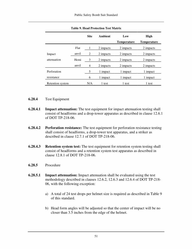
Public Safety Bomb Suit Standard
51
Table 9. Head Protection Test Matrix
Site Ambient Low
Temperature
High
Temperature
Impact
attenuation
Flat
anvil
1 2 impacts 2 impacts 2 impacts
2 2 impacts 2 impacts 2 impacts
Hemi
anvil
3 2 impacts 2 impacts 2 impacts
4 2 impacts 2 impacts 2 impacts
Perforation
resistance
5 1 impact 1 impact 1 impact
6 1 impact 1 impact 1 impact
Retention system N/A 1 test 1 test 1 test
6.28.4 Test Equipment
6.28.4.1 Impact attenuation: The test equipment for impact attenuation testing shall consist of headforms and a drop-tower apparatus as described in clause 12.6.1 of DOT TP-218-06.
6.28.4.2 Perforation resistance: The test equipment for perforation resistance testing shall consist of headforms, a drop-tower test apparatus, and a striker as described in clause 12.7.1 of DOT TP-218-06.
6.28.4.3 Retention system test: The test equipment for retention system testing shall consist of headforms and a retention system test apparatus as described in clause 12.8.1 of DOT TP-218-06.
6.28.5 Procedure
6.28.5.1 Impact attenuation: Impact attenuation shall be evaluated using the test methodology described in clauses 12.6.2, 12.6.3 and 12.6.4 of DOT TP-218-06, with the following exception:
a) A total of 24 test drops per helmet size is required as described in Table 9
of this standard.
b) Head form angles will be adjusted so that the center of impact will be no closer than 3.5 inches from the edge of the helmet.

Public Safety Bomb Suit Standard
52
6.28.5.2 Perforation resistance: Perforation resistance shall be evaluated using the test methodology described in clauses 12.7.2 and 12.7.3 of DOT TP-218-06 with the following exception:
a) A total of six test drops per helmet size is required as described in Table 9 of this standard.
6.28.5.3 Retention system: The retention system shall be evaluated using the test methodology described in clause 12.8.2 of DOT TP-218-06 with the following exception:
a) Three retention system tests per helmet size are required as described in Table 9 of this standard.
6.28.6 Report
6.28.7 All results and observations shall be recorded and reported.
6.29 Spine Protection TestA
6.29.1 Samples
6.29.1.1 Three facsimile samples, each, of the spine protector for the smallest and largest size bomb suit offered by the supplier (including any component layers associated with the spine protector) shall be submitted for impact attenuation evaluation. Coverage area (length x width) of the spine protector shall be specified by the supplier when submitting the bomb suit for evaluation. All facsimile samples shall be compared with a bomb suit sample to verify that materials and construction are identical.
6.29.1.2 For conditioning, three samples shall be exposed as follows:
• High temperature conditions: One sample shall be exposed as specified in CSA/CAN Z617-06, clauses 11.3.1 and 11.3.2.
• Low temperature conditions: One sample shall be exposed as specified in CSA/CAN Z617-06, clauses 11.3.1 and 11.3.3.
• Ambient conditions: One sample shall be exposed to a temperature of
21°C ± 2.9°C (70°F ± 5.2°F) for a minimum of 4 hours and not more than 24 hours.

Public Safety Bomb Suit Standard
53
6.29.2 Test Equipment
6.29.2.1 The test equipment shall consist of a support anvil for the spine protector and one impactor representing sphere threat, as described in clauses 11.4.4.1.7 and 11.4.4.2 of CSA/CAN Z617-06.
6.29.3 Test Sequence
6.29.3.1 The test sequence shall be two impacts to each specimen using the sphere threat at the threat energy of 45 J for each spine protector sample in accordance with the test specifications described in clauses 11.4.5.1 and 11.4.5.3 of CSA/CAN Z617-06.
6.29.4 Procedure
6.29.4.1 Impact attenuation shall be evaluated for each environmental condition using the test methodology described in clause 11.4 of CSA/CAN Z617-06. The following exceptions apply:
a) Impact shall be via a gravity drop method.
b) If the construction of the spine protector is not uniform, the minimum number of impacts required in Section 6.29.3 shall be repeated for all portions of the spine protectors where the protection performance is expected to differ.
6.29.5 Report
6.29.5.1 All data and observations shall be recorded and reported, and digital photos of the samples shall be taken before and after the procedure.
6.30 Fragmentation TestA
6.30.1 Samples
6.30.1.1 Fragmentation requirements for seven different armor types are defined in Table 8. Table 10 identifies the corresponding protection area for each armor type. Each protection area represents an area of coverage on the human body as defined in Appendix A.

Public Safety Bomb Suit Standard
54
Table 10. Armor Types and Protection Areas for Fragmentation Testing
6.30.1.2 The required number of test samples that shall be submitted for fragmentation testing for each protection area is defined in Sections 6.30.1.3 and 6.30.1.4.
6.30.1.3 Helmets and face shields shall be used as the test samples for both the head
and face protection areas.
• If the helmet and face shield design is such that both are necessary to meet the fragmentation protection requirements, then the helmet and face shield shall be tested as a system. Otherwise, the helmet and face shield shall be tested independently.
• For the head protection area, the helmet shell and all ballistic-resistant materials used in construction of the helmet shall be submitted for testing.
o A total of six samples shall be submitted for testing, and a V50 ballistic limit test shall be performed on each sample individually. Half of the samples shall be used for each of the two test projectiles specified.
o Helmet accessories, nonballistic-resistant liner materials, and retention systems (if detachable) are not to be used for fragmentation testing.
Armor Type Protection Area Description
A
Thorax/abdomen - Front Medial
Pelvis - Front Medial
Neck - Front Medial
B Face
C Head
D Legs – Upper Front
E
Thorax/abdomen - Front Lateral
Neck - Front Lateral
Pelvis - Front Lateral
F Thorax/abdomen - Rear
Arms
Neck - Rear
Legs – Lower Front
G Pelvis - Rear
Legs - Rear

Public Safety Bomb Suit Standard
55
• For the face protection area, the face shield shall be submitted for testing.
o A minimum of three face shields shall be submitted for testing, and a V50 ballistic limit test shall be performed on each face shield individually. However, additional face shields shall be used if a single face shield does not have sufficient area to meet the V50 ballistic limit test shot spacing requirements.
o If the face shield assembly includes both transparent and opaque regions of different construction, these two regions must be tested separately to determine the V50 ballistic limit of each region.
6.30.1.4 Facsimile samples for protection areas that contain fabric ballistic-resistant materials shall be submitted for fragmentation testing. (The term facsimile
sample, as used in this context, is commonly referred to as a shoot pack.) All facsimile samples shall be compared with a bomb suit sample to verify that materials and construction are identical.
• For protection areas that do not contain rigid ballistic inserts:
o Six facsimile samples for each armor type shall be submitted for testing, and a V50 ballistic limit test shall be performed on each facsimile sample individually. Half of the facsimile samples shall be used for each of the two test projectiles specified.
o Facsimile samples shall be sized 38 cm x 38 cm (15 inches x 15 inches).
• For protection areas that contain rigid ballistic inserts:
o Facsimile samples shall be a minimum size of 38 cm x 38 cm (15 inches x 15 inches) or an appropriately sized rectangle with enough area to fit the ballistic insert and allow stitching across all four edges. If the ballistic insert is sufficiently small, multiple ballistic inserts may be used in a single facsimile sample with stitching in the facsimile sample to hold the ballistic inserts in position. The edges of the ballistic inserts constitute the edges referenced in the edge requirements in Section 6.30.3.5.
o Additional facsimile samples shall be used if the ballistic insert within a single facsimile sample does not have sufficient area to meet the V50 ballistic limit test shot spacing requirements.

Public Safety Bomb Suit Standard
56
6.30.1.5 For conditioning, samples shall be exposed to 20˚C ± 5.5˚C (68˚F ± 10˚F) and 20% to 70% rh for a minimum of 24 hours before testing.
6.30.2 Test Equipment and Conditions
6.30.2.1 Test facility: The test facility shall provide the conditions necessary to meet the requirements stated in the following sections.
6.30.2.2 Launcher to target distance: The spacing from the launcher muzzle to the target shall be 5.0 m ± 1.0 m (16.4 ft ± 3.28 ft). The spacing from the launcher muzzle to the first pair of triggering devices shall be sufficient to prevent damage from muzzle blast and obstruction from smoke in case optical devices are used. Recommended distances can be found in ITOP 4-2-805. The last pair of triggering devices shall be placed as close as possible to the test sample but no farther than 1.5 m (5 ft) and shall be protected from possible damage resulting from fragments.
6.30.2.3 Launching system: Any launching device may be used, provided that it is capable of consistently propelling the test projectiles at the required aiming point with an acceptable accuracy, impact velocity, angle of impact, and yaw.
6.30.2.4 Projectile velocity measurement: Projectile velocity measurement methods shall employ either high velocity lumiline screens or electrical contact screens that either open or close an electric circuit on passage of the projectile through the detector. Contact screens may consist of metallic foils separated by a thin insulating layer, or may consist of a circuit printed on paper with the circuit spacing, such that the projectile passing through the screen will break the circuit. An electric-counter-type chronograph measuring to the nearest microsecond, or at most 10 microseconds, shall be used with these measuring devices. Alternatively, radiographic or radar equipment capable of calculating projectile velocity may be used. Velocity correction methodology shall be used to calculate the actual striking velocity of the projectile.8
6.30.2.5 Projectile yaw measurement: Projectile yaw shall be measured as close to the target as possible for each firing by yaw cards, flash radiograph, or high-speed video. The measurement system employed should be capable of measuring yaw within an accuracy of ± 5 degrees.
6.30.2.6 Witness plate for perforation and stop determination: Perforations and stops shall be determined based on the effects on an aluminum alloy witness
8 See MIL-STD-662F, Section 5.5, and ITOP 4-2-805, Appendix F, for additional information on velocity
correction methodology.

Public Safety Bomb Suit Standard
57
plate rigidly mounted around its perimeter and located behind the specimen. Witness plate material specifications and mounting locations are described in MIL-STD-662F, Section 5.2.2, with the following exception: The witness plate for armor types B and C shall be 0.51 mm (0.02 inches) thick aluminum sheet rigidly mounted 51mm (2 inches) behind the area of impact. Witness plates shall be sized according to the facsimile sample being tested. For example, the 38 cm x 38 cm (15 inches x 15 inches) size facsimile samples will require witness plates of the same size. Smaller size witness plates shall be used for helmet and face shield testing and be of sufficient size to capture all fragments resulting from the ballistic event.
6.30.2.7 Sample retention system: Specimens shall be supported as described in MIL-STD-662F, Section 4.5.
• The frame supports, clamps, or mounting fixtures must be capable of retaining the specimen securely both before and after the ballistic impact by the test projectiles. The test specimen mount shall be capable of withstanding the shock of the ballistic impact by the test projectiles. The test sample mount shall be capable of moving the specimen in the vertical and horizontal directions so that the point of impact can be located anywhere on the specimen and so that appropriate degree obliquity impacts can be achieved anywhere on the specimen. The test specimen mount shall be capable of rotating on the vertical or horizontal axis so that various obliquity attack angles can be achieved.
• For all size specimens, a metallic frame of 5 mm (0.2 inches) thick aluminum or steel with a minimum of 35 mm (1.4 inches) wide webbing shall be employed to restrain the test material during ballistic impact. The specimen shall be sandwiched between two frames and restrained with mechanical or pneumatic clamping devices at each of the four corners of the frame. No shots shall be closer than 64 mm (2.5 inches) from any internal frame edge. For all facsimile samples, the restraining frames shall be cut to provide an overlap of at least 12.5 mm (0.5 inch) on all edges of the sample.
• Helmet and face shield specimens shall be rigidly mounted and attached to the mount in at least two mounting locations. Accommodations shall be made to ensure that any perforating projectiles do not strike the opposite side of the helmet.
6.30.2.8 Fragment-simulating projectiles shall be used to evaluate the fragmentation protection performance of a bomb suit. Projectiles used shall conform to the details of Table 11.
Table 11. Test Projectiles
Test Projectile Projectile Mass Reference in

Public Safety Bomb Suit Standard
58
MIL-DTL-46593B
.22 cal
FSP
1.1 g
(17 gr)
Figure 1
.30 cal
FSP
2.9 g
(44 gr)
Figure 2
.50 cal
FSP
13.4 g
(207 gr)
Figure 3
6.30.2.9 Test conditions: All tests shall be conducted at 20˚C ± 5.5˚C (68˚F ± 10˚F) and 20% to 70% rh. Temperature and humidity measurements shall be recorded for each test specimen.
6.30.3 Procedure
6.30.3.1 V50 ballistic limit testing shall be performed according to the “up and down” method of firing specified in MIL-STD-662F.
6.30.3.2 A perforation of a test specimen occurs when the impacting projectile, any fragment of the impacting projectile, or any fragment of the test specimen perforates the witness plate, resulting in a crack or hole that permits light passage when a 60 W, 110 V bulb is placed behind the witness plate defined in 6.30.2.6.
6.30.3.3 A fair hit shall have less than 5 degrees projectile yaw.
6.30.3.4 Facsimile samples may be reformed to initial shape after every shot. At a minimum, the specimen shall be reformed when excessive pulling from the restraining fixture is exhibited. Excessive pulling occurs when the fabric extends more than 51 mm (2.0 inches) beyond the original rear surface of the facsimile sample or when the distance between the rear facsimile sample surface is within 102 mm (4.0 inches) of the witness plate.
6.30.3.5 All specimens shall be tested at 0 degree obliquity as defined in MIL-STD-662F, Section 3.20.
a) A fair hit shall meet the minimum distance requirements for shot location detailed in Table 12 unless the supplier specifies a lesser value for minimum distance in advance. The supplier is allowed to specify in advance lesser values for the minimum distances. For a given hit, if the distance from edges, holes, or points of impact of previous shots is less than the minimum specified, the hit is considered fair if the result is a stop.

Public Safety Bomb Suit Standard
59
For facsimile samples, each shot shall be staggered 19 mm (0.75 inches) from points of impact of previous shots off the horizontal and vertical lines.
Table 12. Minimum Distance for Shot Locations
Armor Type Test
Projectile
Distance From
Edges or Holes
Distance From
Impact Points of
Previous Shots
B .22 cal
FSP
25 mm
(1.0 inch)
51 mm
(2.0 inches)
All others .22 cal
FSP
64 mm
(2.5 inches)
64 mm
(2.5 inches)
.30 cal
FSP
64 mm
(2.5 inches)
76 mm
(3.0 inches)
.50 cal
FSP
76 mm
(3.0 inches)
102 mm
(4.0 inches)
6.30.4 Calculation of V50 Ballistic Limit
6.30.4.1 The V50 ballistic limit testing shall use the up-and-down methodology described in Table 13. The V50 ballistic limit shall be calculated by taking the arithmetic mean of the required number of the highest stop (HS) and the lowest perforation (LP) impact velocities of fair hits within the maximum allowable velocity range. The required number of fair hits used to calculate the V50 ballistic limit and the corresponding maximum allowable velocity range for the fair hits used in the calculation are specified in Table 14. If the velocity range is greater than the maximum allowed in Table 14 but the estimated V50 ballistic limit value is greater than the minimum requirement in Table 8, this test shall be considered to be inconclusive and the test may be performed up to two additional times. If after three attempts, the test result is inconclusive, the test result shall be considered a failure.
6.30.4.2 If the specimen’s V50 ballistic limit is so high that the velocity necessary for perforation is not achieved within 5 stops above the V50 limit, the test laboratory shall record that this has occurred and the test will be considered acceptable.

Public Safety Bomb Suit Standard
60
Table 13. V50 Ballistic Limit Parameters
Parameter
Description
Value Section Reference
in MIL-STD-662F
Velocity of first
shot
The V50 ballistic limit for the
armor type and test projectile
(Table 8)
5.3.3
Velocity step until
first reversal
-30.5 m/s (-100 ft/s) if first shot
was a perforation
5.3.5
+ 30.5 m/s (+100 ft/s) if first
shot was a stop
Exception to 5.3.5
Velocity step until
second reversal
±22.9 m/s (±75 ft/s) depending
on result of previous shot
5.3.5
Velocity step after
second reversal
± 15.2 m/s (50 ft/s) depending
on result of previous shot
5.3.5
Table 14. Required Number of Fair Hits and
Maximum Allowable Velocity Range
Armor Type High Stops Low Perforations Velocity Range
B 3 3 38 m/s (125 ft/s)
4 4 45 m/s (150 ft/s)
All others 5 5 38 m/s (125 ft/s)
7 7 45 m/s (150 ft/s)
6.30.5 Report
6.30.5.1 All results and observations shall be recorded and reported.
6.31 Bomb Suit Integrity TestA
6.31.1 Samples
6.31.1.1 One bomb suit shall be provided for this test.

Public Safety Bomb Suit Standard
61
6.31.1.2 The bomb suit shall be sized appropriately based on the test surrogate dimensions and the bomb suit supplier’s specifications.
6.31.1.3 For conditioning, the sample shall be exposed to 21 ± 2.9˚C (70 ± 5˚F) and 50
± 20% rh for a minimum of 12 hours before testing.
6.31.2 Test Equipment and Conditions
6.31.2.1 The ambient temperature shall be between 24 ± 11˚C (75 ± 20˚F) and the
humidity shall be 70 ± 25 % rh. If this test is not performed in a sheltered environment, there shall be no precipitation.
6.31.2.2 A Hybrid III 50th-percentile male crash test dummy shall be used as the test surrogate. The test surrogate shall be kept at the environmental conditions identified by its manufacturer. If no temperature is identified, the temperature
shall be set to 21 ± 2.9˚C (70 ± 5˚F).
6.31.2.3 A positioning fixture shall be provided to properly support and/or suspend the explosive charge such that it cannot interfere with the blast exposure of the test surrogate.
6.31.2.4 A positioning fixture shall be provided to support the test surrogate in the kneeling posture.
6.31.2.5 Two separate free field side-on blast overpressure gauges shall be positioned at a distance of 1.52 m (5 ft) from the explosive charge and a height of 77 cm (30 inches) from its horizontal center to the ground. These gauges shall be used to record blast overpressure values for reference data only.
6.31.2.6 A data acquisition system shall be used to record values from the blast overpressure gauges and shall have an adequate sampling rate to capture the blast event. All data collected shall be sampled at a frequency of 500 kHz. If hardware anti-alias filtering is incorporated, this information shall be recorded.
6.31.2.7 One explosive charge of C4 plastic explosive material is required. The C4 shall be packed into a cylindrical cardboard tube of appropriate dimensions for a length to diameter ratio of one. The test charge shall meet the following criteria:
1. Weight of 1.25 lbs ± 0.002 lbs (567 g ± 1 g) of C4 plastic explosive.
2. The detonator positioned in the charge center.

Public Safety Bomb Suit Standard
62
6.31.2.8 When in a position for detonation, the cylinder shall be oriented vertically (i.e., each end of the cylinder shall be in a horizontal plane).
6.31.3 Procedure
6.31.3.1 The test surrogate shall be clothed in the bomb suit per supplier donning instructions and positioned in a kneeling posture supported by a positioning fixture. The test surrogate shall be positioned so that the exterior of the bomb suit is at a standoff distance of 0.6 m (2 ft) from the test charge. The explosive charge shall be positioned at a distance of 77 cm (30 inches) from its horizontal center to the ground.
6.31.3.2 Photographs of the test setup (including the test surrogate wearing the bomb suit) shall be taken for inclusion in the test report.
6.31.3.3 The explosive charge shall be detonated, and the results shall be recorded and reported. Photographs of the test setup following the explosion shall be taken for inclusion in the test report.
6.32 Drag Rescue Device Test
6.32.1 Samples
6.32.1.1 One sample of a bomb suit appropriately sized to fit the test surrogate described in Section 6.32.2.1 shall be provided for evaluation.
6.32.2 Test Equipment
6.32.2.1 The test surrogate shall be an IAFF “Rescue Randy” model 1475 mannequin, a Hybrid III 50th-percentile male dummy, or equivalent.
6.32.2.2 A 27-kg (60-lb) weighted vest or belt is required to increase the weight of the test surrogate.
6.32.3 Procedure
6.32.3.1 The test assistant shall install the weighted vest or belt on the test surrogate such that the weight is distributed evenly around the torso. The assistant shall place the bomb suit on the test surrogate in accordance with the supplier’s instructions.

Public Safety Bomb Suit Standard
63
6.32.3.2 The test surrogate shall be positioned as specified in NFPA 1971 (2007), Section 8.59.5.6.
6.32.3.3 The test assistant, using a gloved hand9, shall perform the test as specified in NFPA 1971 (2007), Section 8.59.5.10.
6.32.3.4 The above steps shall be performed for each drag rescue device, and the results shall be recorded and reported.
6.33 Label Durability: Wear Test
6.33.1 Samples
6.33.1.1 Three labels shall be submitted for testing. The samples shall include individual labels sewn onto a separate square of material identical to the material to which the label is attached in the construction of the bomb suit.
6.33.2 Procedure
6.33.2.1 The samples shall be tested in accordance with NFPA 1971(2007), Section 8.42.4.2.1, with the exception of item (3).
6.33.2.2 The samples shall be examined in accordance with NFPA 1971 (2007), Section 8.42.4.2.2.
6.34 Label Durability: Chemical Resistance Test
6.34.1 Samples
6.34.1.1 Three labels shall be submitted for testing.
6.34.2 Procedure
6.34.2.1 A representative area of the label markings shall be rubbed by hand for 15 seconds with a cotton cloth soaked with distilled water.
6.34.2.2 The same area shall be rubbed by hand for 15 seconds with a cotton cloth soaked with denatured alcohol (methylated spirit).
9 The glove shall be a commonly used type of work glove for protection against sharp edges and similar
physical hazards.

Public Safety Bomb Suit Standard
64
6.34.2.3 The same area shall be rubbed by hand for 15 seconds with cotton cloth soaked with isopropyl alcohol.
6.34.2.4 The samples shall be examined in accordance with NFPA 1971 (2007), Section 8.42.4.2.2.
6.35 Slip Resistance Test
6.35.1 Samples
6.35.1.1 Two test samples per type of foot protection material shall be tested.
6.35.2 Procedure
6.35.2.1 Test samples representing the walking surface of the foot protection shall be submitted for evaluation in accordance with ASTM F 489, Standard Test
Method for Static Coefficient of Friction of Shoe Sole and Heel Materials as
Measured by the James Machine, for dry conditions.
6.35.2.2 The static coefficient of friction of each sample shall be recorded and reported.

Public Safety Bomb Suit Standard
65
7. LABELING AND INFORMATION
7.1 General Product Label Requirements for Bomb Suit Models
7.1.1 Each detachable protective element of the bomb suit, with the exception of the face shield, shall have a product label permanently attached to, embossed on, or printed on an inside surface.
7.1.2 The face shield shall have a product label permanently attached to, embossed on, or printed on it in letters at least 2 mm (1/16 inch) high. The product label shall include at least the model number and serial number.
7.1.3 All worded portions of a required product label shall appear in English, but other languages may be added.
7.1.4 Symbols and other graphical information may be used to supplement text on the product label(s) and shall be explained in the user information.
7.1.5 For each compliant bomb suit model, each certified-product label shall include the applicable compliance and information statements specified in Section 7.2.
7.1.6 In addition to the compliance and information statements required by Section 7.1.5, each detachable protective element of the bomb suit, with the exception of the face shield, shall have at least the following information printed legibly on the product label(s) in letters a minimum of 3.2 mm (1/8 inch) high:
• Name and legal address of the supplier.
• Address of manufacturing location (city, state/province, country).
• Date of manufacture (i.e., month and year).
• Bomb suit model number.
o If the bomb suit model has detachable protective elements, the bomb suit product label shall include the detachable protective element model numbers for the protective elements that must be used in order for the bomb suit model to be compliant.
• Serial number for the bomb suit.
• Size.
• Assembly orientation of any protective element if necessary for performance requirements of this standard (e.g., strike face, wear face).

Public Safety Bomb Suit Standard
66
7.2 Compliance Statements on Certified Product Labels of Compliant Bomb Suit
Models
7.2.1 Placement of any compliance statement on the certified product label shall be consistent with Sections 7.1.1 and 7.1.2.
7.2.2 A certified product shall have the following compliance statement on the bomb suit product label in letters at least 2.5 mm (3/32 inch) high.
“PURSUANT TO NIJ CR-0117.01, THIS BOMB SUIT MODEL HAS BEEN TESTED AND FOUND TO BE COMPLIANT WITH THE
REQUIREMENTS OF NIJ STANDARD-0117.01 (PUBLIC SAFETY BOMB SUIT STANDARD). DO NOT REMOVE THIS LABEL.”
7.3 User Information to be Provided by the Supplier
7.3.1 In order to have a bomb suit model tested under this standard, the supplier must agree that, if the model is found to be compliant, it will provide written user information including, but not limited to, warnings, information, and instructions with each individual bomb suit (and with each protective element that may be acquired or provided separately).
7.3.2 The supplier shall provide the required user information in such a manner as to make such information clear, prominent, and immediately available to any individual opening the package.
7.3.3 The supplier shall provide at least the following warnings, information, and instructions as part of the written user information:
• List of required accessories provided with the bomb suit or protective element.
• Pre-use information as follows:
o Safety considerations.
o Recommendations and precautions regarding the application of public safety agency markings after purchase.
o Any limitations or precautions as to type(s) of clothing worn under the bomb suit.
o Description of mechanism(s) to prevent condensation on the face shield.
o Warranty information, including length of warranty.
• Donning and doffing information as follows:
Public Safety Bomb Suit Standard
67
o Donning and doffing procedures, including quick doffing and incapacitated doffing, and any bomb suit protective element interface considerations.
o Sizing and adjustment procedures,
• Instructions for proper use as intended by the supplier.
• Care and maintenance, as follows:
o Cleaning instructions and precautions.
o Recommended decontamination procedures.
o Recommended storage conditions.
o Inspection details.
o Repair methods, where applicable.
o Retirement and disposal criteria and considerations.
7.4 Technical Data Package to be Provided by the Supplier
7.4.1 In order to have a bomb suit model tested under this standard, the supplier must agree that, if the model is found to be compliant, it will furnish, as set forth in this section, a technical data package for the bomb suit model upon the request of the purchaser or the prospective purchaser.
7.4.2 The technical data package shall contain all data showing compliance of the model with this standard. In particular, for any test in which the result is recorded and reported only (i.e., not having an associated pass/fail requirement), the result shall be included in the technical data package.
7.4.3 In the technical data package, the supplier shall describe the bomb suit model in terms of the supplier name, trade name, model number, supplier-replaceable protective elements and components, and available sizes.
7.4.3.1 Descriptions of size shall include the ranges in height and weight for persons fitting each particular available size of bomb suit.
7.4.3.2 The technical data package shall include a list and descriptions of the following with respect to the bomb suit model, as applicable:
• All protective elements and components.
o Face shield: Permanent or removable appliqués or films. o Protective element and component methods of attachment.
• Required accessories.
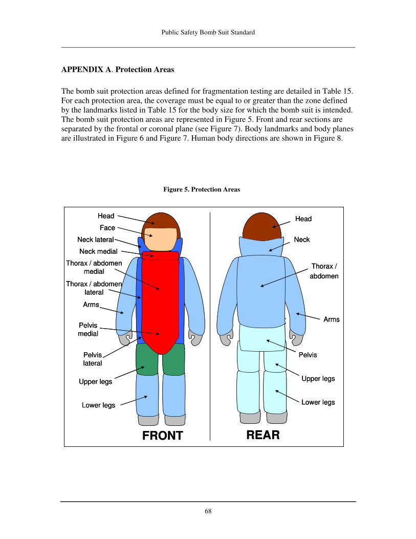
Public Safety Bomb Suit Standard
68
APPENDIX A. Protection Areas
The bomb suit protection areas defined for fragmentation testing are detailed in Table 15. For each protection area, the coverage must be equal to or greater than the zone defined by the landmarks listed in Table 15 for the body size for which the bomb suit is intended. The bomb suit protection areas are represented in Figure 5. Front and rear sections are separated by the frontal or coronal plane (see Figure 7). Body landmarks and body planes are illustrated in Figure 6 and Figure 7. Human body directions are shown in Figure 8.
Figure 5. Protection Areas
REAR
Thorax /
abdomen
Neck
Upper legs
Arms
Lower legs
Pelvis
lateral
Head
Face
Thorax / abdomen
lateral
Neck medial
Thorax / abdomen
medial
FRONT
Neck lateral
Pelvis
medial
Pelvis
Arms
Upper legs
Lower legs
Head
REAR
Thorax /
abdomen
Neck
Upper legs
Arms
Lower legs
Pelvis
lateral
Head
Face
Thorax / abdomen
lateral
Neck medial
Thorax / abdomen
medial
FRONT
Neck lateral
Pelvis
medial
Pelvis
Arms
Upper legs
Lower legs
Head

Public Safety Bomb Suit Standard
69
Table 15. Bomb Suit Protection Area
Armor
Type
Protection Area
Description
Body Landmarks
Medial/Lateral Superior/
Proximal Interior/Distal
A
Thorax/ Abdomen – Front
Medial
Front thorax/abdomen
between bust points Sternale Omphalion
Pelvis - Front Medial Front pelvis between
bust points Omphalion Crotch level
Neck – Front Medial Front neck between
bust points Menton Sternale
B Face Front head (Note 1) Note 1 Note 1
C Head Entire head without
face area Vertex
Nuchale
Menton
Gonion
D Legs – Upper Front Front upper legs Crotch level
Femoral epicondyles
Trochanterion Mid-patella
E
Thorax/ Abdomen – Front Lateral
Front thorax/abdomen lateral to the bust
points
Sternale Omphalion
Neck – Front Lateral Front neck lateral to
the bust points
Nuchale Cervicale
Menton Sternale
Pelvis – Front Lateral Front pelvis lateral to the bust points
Omphalion Crotch level
Gluteal furrow
F
Thorax/ Abdomen - Rear
Rear thorax/abdomen Cervicale Omphalion
Arms Front and rear arms
Acromion Radial styloid
Anterior scye Stylion
Posterior scye Wrist crease
Neck - Rear Rear neck Nuchale Cervicale
Legs – Lower Front Front lower legs
Femoral Epicondyles
Medial malleolus
Mid-patella
Lateral malleolus
Ankle crease
G
Pelvis - Rear Rear pelvis Omphalion Gluteal furrow
Legs - Rear Rear legs
Gluteal furrow Medial
malleolus
Trochanterion Lateral
Malleolus
Ankle crease
Note 1: Area large enough to meet FOV requirements.

Public Safety Bomb Suit Standard
70
Figure 7. Human Body Plane: (1) Frontal or
Coronal, (2) Sagittal, (3) Transverse
Figure 8. Human Body Directions
Figure 6. Body Landmarks