pts 4v ptk 4 - wacker neusonproducts.wackerneuson.com/manuals/operators/0154628en_005.pdf · pts 4v...
TRANSCRIPT

Pump
PTS 4VPTK 4
OPERATOR’S MANUAL
0154628en 005
0107
0 1 5 4 6 2 8 E N


PTS 4V / PTK 4 Table of Contents
1. Foreword 3
2. Safety Information 4
2.1 Laws Pertaining to Spark Arresters ...................................................... 4
2.2 Operating Safety .................................................................................. 5
2.3 Operator Safety while using Internal Combustion Engines .................. 6
2.4 Service Safety ...................................................................................... 7
2.5 Label Locations ................................................................................. 8
2.6 Safety Labels ........................................................................................ 9
3. Technical Data 11
3.1 Engine ................................................................................................ 11
3.2 Pump .................................................................................................. 12
3.3 Sound Measurements ........................................................................ 13
3.4 Dimensions ......................................................................................... 13
4. Operation 14
4.1 Application .......................................................................................... 14
4.2 Recommended Fuel ........................................................................... 14
4.3 Before Starting ................................................................................... 14
4.4 To Start ............................................................................................... 16
4.5 To Stop ............................................................................................... 17
4.6 Operation ............................................................................................ 17
4.7 Pump Wrench ..................................................................................... 17
4.8 Accessories ........................................................................................ 18
4.9 Hoses and Clamps ............................................................................. 18
wc_bo0154628en_005TOC.fm 1

Table of Contents PTS 4V / PTK 4
5. Maintenance 19
5.1 Periodic Maintenance Schedule ..........................................................195.2 Engine Lubrication ...............................................................................205.3 Changing Oil Filter ...............................................................................215.4 Air Cleaner ..........................................................................................225.5 Spark Plug ...........................................................................................235.6 Fuel Filter ............................................................................................245.7 Carburetor Adjustment ........................................................................245.8 Mechanical Seal Lubrication ...............................................................255.9 Adjusting Impeller Clearance ..............................................................265.10 Cleaning Pump ....................................................................................275.11 Storage ................................................................................................285.12 Lifting ...................................................................................................285.13 Troubleshooting ...................................................................................29
wc_bo0154628en_005TOC.fm 2

wc_tx000001gb.fm 3
CALIFORNIA
Proposition 65 Warning:
Engine exhaust, some of its constituents, and certain vehiclecomponents, contain or emit chemicals known to the State ofCalifornia to cause cancer and birth defects or other reproductiveharm.
1. Foreword
This manual provides information and procedures to safely operateand maintain this Wacker model. For your own safety and protectionfrom injury, carefully read, understand and observe the safetyinstructions described in this manual.
Keep this manual or a copy of it with the machine. If you lose thismanual or need an additional copy, please contact WackerCorporation. This machine is built with user safety in mind; however,it can present hazards if improperly operated and serviced. Followoperating instructions carefully! If you have questions about operatingor servicing this equipment, please contact Wacker Corporation.
The information contained in this manual was based on machines inproduction at the time of publication. Wacker Corporation reserves theright to change any portion of this information without notice.
All rights, especially copying and distribution rights, are reserved.
Copyright 2007 by Wacker Corporation.
No part of this publication may be reproduced in any form or by anymeans, electronic or mechanical, including photocopying, withoutexpress written permission from Wacker Corporation.
Any type of reproduction or distribution not authorized by WackerCorporation represents an infringement of valid copyrights and will beprosecuted. We expressly reserve the right to make technicalmodifications, even without due notice, which aim at improving ourmachines or their safety standards.
WARNING

Safety Information PTS 4V / PTK 4
2. Safety Information
This manual contains DANGER, WARNING, CAUTION, and NOTEcallouts which must be followed to reduce the possibility of personalinjury, damage to the equipment, or improper service.
This is the safety alert symbol. It is used to alert you to potentialpersonal injury hazards. Obey all safety messages that follow thissymbol to avoid possible injury or death.
DANGER indicates a hazardous situation which, if not avoided, willresult in death or serious injury.
WARNING indicates a hazardous situation which, if not avoided, couldresult in death or serious injury.
CAUTION indicates a hazardous situation which, if not avoided, couldresult in minor or moderate injury.
CAUTION: Used without the safety alert symbol, CAUTION indicatesa potentially hazardous situation which, if not avoided, may result inproperty damage.
Note: Contains additional information important to a procedure.
2.1 Laws Pertaining to Spark Arresters
Notice: State Health Safety Codes and Public Resources Codesspecify that in certain locations spark arresters be used on internalcombustion engines that use hydrocarbon fuels. A spark arrester is adevice designed to prevent accidental discharge of sparks or flamesfrom the engine exhaust. Spark arresters are qualified and rated bythe United States Forest Service for this purpose.
In order to comply with local laws regarding spark arresters, consultthe engine distributor or the local Health and Safety Administrator.
DANGER
WARNING
CAUTION
wc_si000130gb.fm 4
PTS 4V / PTK 4 Safety Information
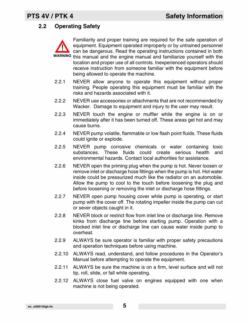
2.2 Operating Safety
Familiarity and proper training are required for the safe operation ofequipment. Equipment operated improperly or by untrained personnelcan be dangerous. Read the operating instructions contained in boththis manual and the engine manual and familiarize yourself with thelocation and proper use of all controls. Inexperienced operators shouldreceive instruction from someone familiar with the equipment beforebeing allowed to operate the machine.
2.2.1 NEVER allow anyone to operate this equipment without propertraining. People operating this equipment must be familiar with therisks and hazards associated with it.
2.2.2 NEVER use accessories or attachments that are not recommended byWacker. Damage to equipment and injury to the user may result.
2.2.3 NEVER touch the engine or muffler while the engine is on orimmediately after it has been turned off. These areas get hot and maycause burns.
2.2.4 NEVER pump volatile, flammable or low flash point fluids. These fluidscould ignite or explode.
2.2.5 NEVER pump corrosive chemicals or water containing toxicsubstances. These fluids could create serious health andenvironmental hazards. Contact local authorities for assistance.
2.2.6 NEVER open the priming plug when the pump is hot. Never loosen orremove inlet or discharge hose fittings when the pump is hot. Hot waterinside could be pressurized much like the radiator on an automobile.Allow the pump to cool to the touch before loosening the plug andbefore loosening or removing the inlet or discharge hose fittings.
2.2.7 NEVER open pump housing cover while pump is operating, or startpump with the cover off. The rotating impeller inside the pump can cutor sever objects caught in it.
2.2.8 NEVER block or restrict flow from inlet line or discharge line. Removekinks from discharge line before starting pump. Operation with ablocked inlet line or discharge line can cause water inside pump tooverheat.
2.2.9 ALWAYS be sure operator is familiar with proper safety precautionsand operation techniques before using machine.
2.2.10 ALWAYS read, understand, and follow procedures in the Operator’sManual before attempting to operate the equipment.
2.2.11 ALWAYS be sure the machine is on a firm, level surface and will nottip, roll, slide, or fall while operating.
2.2.12 ALWAYS close fuel valve on engines equipped with one whenmachine is not being operated.
WARNING
wc_si000130gb.fm 5

Safety Information PTS 4V / PTK 4
2.2.13 ALWAYS store the equipment properly when it is not being used.Equipment should be stored in a clean, dry location out of the reach ofchildren.
2.2.14 ALWAYS wear hearing protection when operating equipment.
2.3 Operator Safety while using Internal Combustion Engines
Internal combustion engines present special hazards during operationand fueling. Read and follow the warning instructions in the engineowner’s manual and the safety guidelines below. Failure to follow thewarnings and safety guidelines could result in severe injury or death.
2.3.1 DO NOT run the machine indoors or in an enclosed area such as adeep trench unless adequate ventilation, through such items asexhaust fans or hoses, is provided. Exhaust gas from the enginecontains poisonous carbon monoxide gas; exposure to carbonmonoxide can cause loss of consciousness and may lead to death.
2.3.2 DO NOT smoke while operating the machine.
2.3.3 DO NOT smoke when refueling the engine.
2.3.4 DO NOT refuel a hot or running engine.
2.3.5 DO NOT refuel the engine near an open flame.
2.3.6 DO NOT spill fuel when refueling the engine.
2.3.7 DO NOT run the engine near open flames.
2.3.8 ALWAYS refill the fuel tank in a well-ventilated area.
2.3.9 ALWAYS replace the fuel tank cap after refueling.
DANGER
wc_si000130gb.fm 6

PTS 4V / PTK 4 Safety Information
2.4 Service Safety
Poorly maintained equipment can become a safety hazard! In orderfor the equipment to operate safely and properly over a long period oftime, periodic maintenance and occasional repairs are necessary.
2.4.1 DO NOT attempt to clean or service the machine while it is running.Rotating parts can cause severe injury.
2.4.2 DO NOT crank a flooded engine with the spark plug removed ongasoline-powered engines. Fuel trapped in the cylinder will squirt outthe spark plug opening.
2.4.3 DO NOT test for spark on gasoline-powered engines if the engine isflooded or the smell of gasoline is present. A stray spark could ignitethe fumes.
2.4.4 DO NOT use gasoline or other types of fuels or flammable solvents toclean parts, especially in enclosed areas. Fumes from fuels andsolvents can become explosive.
2.4.5 ALWAYS operate machine with all safety devices and guards in placeand in working order. DO NOT modify or defeat safety devices. DONOT operate machine if any safety devices or guards are missing orinoperative.
2.4.6 ALWAYS keep the area around the muffler free of debris such asleaves, paper, cartons, etc. A hot muffler could ignite the debris andstart a fire.
2.4.7 ALWAYS replace worn or damaged components with spare partsdesigned and recommended by Wacker Corporation.
2.4.8 ALWAYS disconnect the spark plug on machines equipped withgasoline engines, before servicing, to avoid accidental start-up.
2.4.9 ALWAYS keep the machine clean and labels legible. Replace allmissing and hard-to-read labels. Labels provide important operatinginstructions and warn of dangers and hazards.
2.4.10 ALWAYS handle impeller carefully. The impeller can develop sharpedges which can cut.
WARNING
wc_si000130gb.fm 7
Safety Information PTS 4V / PTK 4
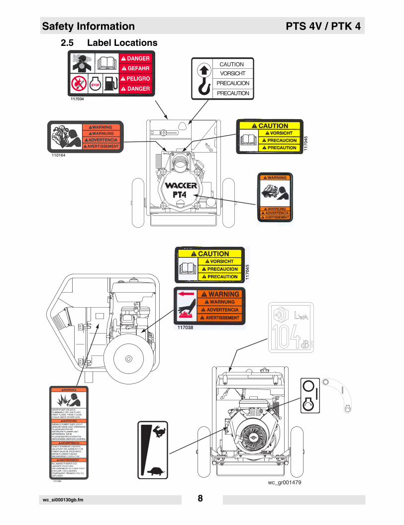
2.5 Label Locations
wc_gr001479
PRECAUTION
PRECAUCION
VORSICHT
CAUTION
wc_si000130gb.fm 8

PTS 4V / PTK 4 Safety Information
2.6 Safety Labels
Wacker machines use international pictorial labels where needed.These labels are described below:
Label Meaning
DANGER!Engines emit carbon monoxide; operate only in well-ventilated area. Read the Operator’s Manual.No sparks, flames, or burning objects near the machine. Shut off the engine before refueling.
WARNING! Hot surface!
CAUTION!Read and understand the supplied Operator’s Manuals before operating this machine. Failure to do so increases the risk of injury to yourself or others.
WARNING! Do not open if pump is hot. Hot water and/or steam inside could be pressurized.
WARNING! Never pump volatile, flammable or low flash point fluids. These fluids could ignite or explode.
CAUTION! Lifting point
PRECAUTION
PRECAUCION
VORSICHT
CAUTION
wc_si000130gb.fm 9

Safety Information PTS 4V / PTK 4
Guaranteed sound power level in dB(A)
Key switch:offonstart
Throttle control lever:Rabbit = Full or FastTurtle = Idle or Slow
A nameplate listing the model number, item num-ber, revision number, and serial number is attached to each unit. Please record the informa-tion found on this plate so it will be available should the nameplate become lost or damaged. When ordering parts or requesting service infor-mation, you will always be asked to specify the model number, item number, revision number, and serial number of the unit.
This machine may be covered by one or more patents.
Label Meaning
� � � � � � � � � � � � � �
� � � � � � � � � � � � � � � � � � � � � � � � �
� �� � �
! " # � $ � � % � & � ' � �
� ( ! �
� )
� � * �
� � � � �
� + � � � � � �
,,--�
wc_si000130gb.fm 10

PTS 4V / PTK 4 Technical Data
3. Technical Data
3.1 Engine
Item No. PTS 4V0007683 Rev 115 & lower0007691 Rev 116 & lower
0007692
PTS 4V0007683 Rev 116 & higher0007691 Rev 117 & higher
Engine
Engine Make Briggs and Stratton
Engine Model Vanguard 303447-1256-E2
Vanguard 305447-0144-E1
Rated Power kW (Hp) 12 (16)
Spark Plug Champion RC12YC
Electrode Gap mm (in.) 0.76 (0.030)
Engine Speed rpm 3600
Air Cleaner type Dual element
Battery V/CCA/amp-hr./size
12 / 230 / 32 / 22NF
Engine Lubrication oil grade /service class
>5°C (40°F) SAE 10W30 / SG, SF, or SE<5°C (40°F) SAE 30W / SG, SF, or SE
Engine Oil Capacity ml (oz.) 1400 (48)
Fuel type Regular unleaded gasoline
Fuel Tank Capacity l (gal.) 17 (4.5)
wc_td000132gb.fm 11

Technical Data PTS 4V / PTK 4
3.2 Pump
Item number: PTS 4V0007683, 0007691, 0007692
Pump
Weight kg (lbs.) 163 (360)
*Max. Suction Lift m (ft.) 7.5 (25)
Max. Total Head m (ft.) 32 (106)
Mechanical Seal Lubrication oil grademl (oz.)
SAE 30150 (5)
Suction / Discharge Diameter mm (in.) 100 (4)
Max. Solid Size mm (in.) 50 (2)
*Based on pump operating at sea level. Maximum suction lift will be less at higher altitudes.
wc_td000132gb.fm 12

PTS 4V / PTK 4 Technical Data
3.3 Sound Measurements
The required sound specifications per Appendix 1, Paragraph 1.7.4 ofthe EC-Machine Regulations, is:
• the guaranteed sound power level (LWA) = 104 dB(A)
These sound values were determined according to ISO 3744 for thesound power (LWA).
The sound measurements were obtained with the unit operating onpavement at nominal speed.
3.4 Dimensionsmm (in.)
890 (35) 915 (36)
890(35)
wc_gr001478
wc_td000132gb.fm 13

Operation PTS 4V / PTK 4
4. Operation
4.1 Application
This pump is intended for removing clean water and water containingsome debris and solids. Refer to “Technical Data” for maximum solidsize.
4.1.1 NEVER pump volatile, flammable or low flash point fluids. These fluidscould ignite or explode.
4.1.2 NEVER pump corrosive chemicals or water containing toxicsubstances. These fluids could create serious health andenvironmental hazards. Contact local authorities for assistance.
4.2 Recommended Fuel
The engine requires regular grade unleaded gasoline. Use only fresh,clean gasoline. Gasoline containing water or dirt will damage fuelsystem. Consult engine Owner’s Manual for complete fuelspecifications.
4.3 Before Starting
See Graphic: wc_gr000013
4.3.1 Read safety instructions at the beginning of manual.
4.3.2 Place pump as near to water as possible, on a firm, flat, level surface.
4.3.3 To prime pump, remove prime plug (a) and fill pump case with water.If the pump case is not filled with water before starting, it will not beginpumping.
DO NOT open priming plug, discharge plug, or loosen hose fittings ifpump is hot! Water or vapor inside pump may be under pressure.
4.3.4 Check for leaks between pump and engine. If water is leaking, the sealinside pump is worn or damaged. Continued operation may causewater damage to engine.
WARNING
WARNING
WARNING
wc_tx000339gb.fm 14

PTS 4V / PTK 4 Operation
4.3.5 Check that hoses are securely attached to pump. Suction hose (b)must not have any air leaks. Tighten hose clamps (c) and couplings(d). Check that discharge hose (e) is not restricted. Lay hose out asstraight as possible. Remove any twists or sharp bends from hosewhich may block the flow of water.
4.3.6 Make sure suction strainer (f) is clean and securely attached to end ofhose. The strainer is designed to protect the pump by preventing largeobjects from being pulled into the pump.
CAUTION: Strainer should be positioned so it will remain completelyunder water. Running the pump with the strainer above water for longperiods can damage the pump.
4.3.7 Check fuel level, engine oil level, and condition of air cleaner.
wc_tx000339gb.fm 15
Operation PTS 4V / PTK 4
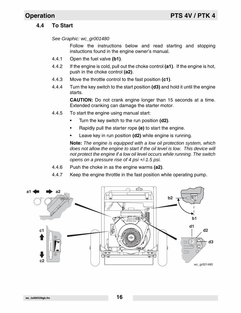
4.4 To Start
See Graphic: wc_gr001480
Follow the instructions below and read starting and stoppinginstuctions found in the engine owner’s manual.
4.4.1 Open the fuel valve (b1).
4.4.2 If the engine is cold, pull out the choke control (a1). If the engine is hot,push in the choke control (a2).
4.4.3 Move the throttle control to the fast position (c1).
4.4.4 Turn the key switch to the start position (d3) and hold it until the enginestarts.
CAUTION: Do not crank engine longer than 15 seconds at a time.Extended cranking can damage the starter motor.
4.4.5 To start the engine using manual start:
• Turn the key switch to the run position (d2).
• Rapidly pull the starter rope (e) to start the engine.
• Leave key in run position (d2) while engine is running.
Note: The engine is equipped with a low oil protection system, whichdoes not allow the engine to start if the oil level is low. This device willnot protect the engine if a low oil level occurs while running. The switchopens on a pressure rise of 4 psi +/-1.5 psi.
4.4.6 Push the choke in as the engine warms (a2).
4.4.7 Keep the engine throttle in the fast position while operating pump.
wc_gr001480
d1d2
d3
b2
b1
c1
c2
a1 a2
wc_tx000339gb.fm 16

PTS 4V / PTK 4 Operation
4.5 To Stop
See Graphic: wc_gr001480
4.5.1 Reduce engine RPM by moving the throttle completely to the idleposition (c2).
4.5.2 Turn the engine switch to the stop position (d1).
4.5.3 Close the fuel valve (b2).
4.6 Operation
Pump should begin pumping water within a minute depending onlength of suction hose and height of pump above water. Longer hoseswill require more time.
If pump does not prime, check for loose fittings or air leak in suctionhose. Make sure strainer in water is not blocked.
Run engine at full speed while operating pump.
4.6.1 NEVER pump corrosive chemicals or water containing toxicsubstances. These fluids could create serious health andenvironmental hazards. Contact local authorities for assistance.
4.7 Pump Wrench
See Graphic: wc_gr001481
The wrench (a) supplied with the pump can be used to loosen andtighten: hose couplings, knobs on pump cover, priming plug, and drainplug on front cover.
Store wrench on pump frame.
WARNING
a
wc gr001481
wc_tx000339gb.fm 17

Operation PTS 4V / PTK 4
4.8 Accessories
Wacker offers a complete line of fittings, hoses, and clamps to properlyconnect the pump to match various job conditions.
4.9 Hoses and Clamps
See Graphic: wc_gr000021
Suction hoses (a) must be rigid enough not to collapse when pump isoperating.
Discharge hoses (b) are usually thin-walled collapsible hoses. Rigidhoses similar to those used as suction hoses may also be used asdischarge hoses.
Note: Suction and discharge hoses are available from Wacker.Contact your nearest dealer for more information.
Two clamps (c) are recommended for connection of suction hoses toinlet coupling.
Note: This connection is important. Even a small air leak on the suctionside of pump will prevent the pump from priming.
For other hose connections, one T-bolt or worm-gear type clamp isusually sufficient to hold hoses in place. In some cases, slightvariances in hose diameters may make it necessary to add moreclamps in order to maintain tight connections.
wc_tx000339gb.fm 18

PTS 4V / PTK 4 Maintenance
5. Maintenance
5.1 Periodic Maintenance Schedule
The chart below lists basic machine and engine maintenance. Refer tothe engine manufacturer’s Operator’s Manual for additionalinformation on engine maintenance.
Dailybefore
starting
Afterfirst
5 hrs.
Every50
hrs.
Every100 hrs.
Everyyear
Check fuel level.
Check engine oil level.
Inspect for leaks between pump and engine.
Inspect air filter. Clean as needed.
Check external hardware.
Inspect shock mounts for damage.
Change oil in pump housing.
Change engine oil and replace filter.
Replace air cleaner.
Check and clean spark plug.
Replace in-line fuel filter.
Check and adjust valve clearances.
wc_tx000340gb.fm 19

Maintenance PTS 4V / PTK 4
5.2 Engine Lubrication
See Graphic: wc_gr000562
Check engine oil level daily before starting engine. Add oil as required.
5.2.1 To check oil level, place machine on a level surface.
5.2.2 Clean area around oil fill and remove dipstick.
5.2.3 Pour oil (a) slowly, checking oil level occasionally with dipstick.
5.2.4 Fill to full mark on dipstick (b). DO NOT overfill.
5.2.5 When measuring oil level, screw dipstick (c) firmly in place until capbottoms on tube.
. / 0 ) � � � � � 1 -
����
�**
�
�
�
wc_tx000340gb.fm 20
PTS 4V / PTK 4 Maintenance
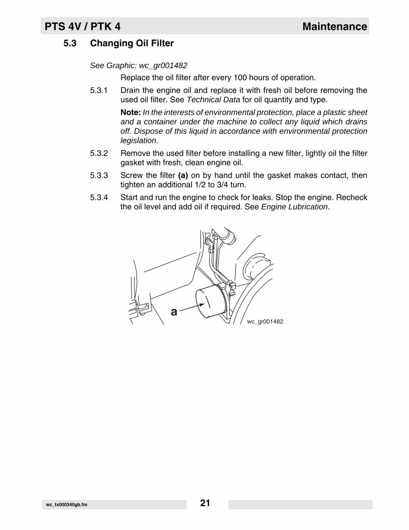
5.3 Changing Oil Filter
See Graphic: wc_gr001482
Replace the oil filter after every 100 hours of operation.
5.3.1 Drain the engine oil and replace it with fresh oil before removing theused oil filter. See Technical Data for oil quantity and type.
Note: In the interests of environmental protection, place a plastic sheetand a container under the machine to collect any liquid which drainsoff. Dispose of this liquid in accordance with environmental protectionlegislation.
5.3.2 Remove the used filter before installing a new filter, lightly oil the filtergasket with fresh, clean engine oil.
5.3.3 Screw the filter (a) on by hand until the gasket makes contact, thentighten an additional 1/2 to 3/4 turn.
5.3.4 Start and run the engine to check for leaks. Stop the engine. Recheckthe oil level and add oil if required. See Engine Lubrication.
awc_gr001482
wc_tx000340gb.fm 21

Maintenance PTS 4V / PTK 4
5.4 Air Cleaner
See Graphic: wc_gr000564
Service air cleaner frequently to prevent carburetor malfunction.
CAUTION: NEVER run the engine without the air cleaner. Severeengine damage will occur.
NEVER use gasoline or other types of low flash point solvents forcleaning the air cleaner. A fire or explosion could result.
The engine is equipped with a dual element air cleaner. To service aircleaner:
5.4.1 Remove cover (a), knob (b), and retaining plate (c).
5.4.2 Remove foam precleaner (d) from filter cartridge (e).
5.4.3 Wash precleaner in liquid detergent and water. Squeeze dry in a cleancloth. Saturate precleaner in engine oil, squeeze out excess oil.Replace precleaner if it is damaged or heavily soiled.
5.4.4 To clean cartridge, remove and tap lightly on a flat surface. Replacecartridge if it is damaged or heavily soiled.
Note: Do not use petroleum solvents to clean precleaner or cartridge.Petroleum type solvents will damage them. Do not use pressurized airto clean cartridge. Pressurized air can also damage the cartridge.
. / 0 ) � � � � � 1 2
�
�
�
�
�
wc_tx000340gb.fm 22

PTS 4V / PTK 4 Maintenance
5.5 Spark Plug
See Graphic: wc_gr000028
Clean or replace the spark plug as needed to ensure proper operation.Refer to the engine owner’s manual.
The muffler becomes very hot during operation and remains hot for awhile after stopping the engine. Do not touch the muffler while it is hot.
Note: Refer to the Technical Data for the recommended spark plugtype and the electrode gap setting.
5.5.1 Remove the spark plug and inspect it.
5.5.2 Replace the spark plug if the insulator is cracked or chipped.
5.5.3 Clean the spark plug electrodes with a wire brush.
5.5.4 Set the electrode gap (a).
5.5.5 Tighten the spark plug securely.
CAUTION: A loose spark plug can become very hot and may causeengine damage.
WARNING
wc_tx000340gb.fm 23

Maintenance PTS 4V / PTK 4
5.6 Fuel Filter
See Graphic: wc_gr001483
5.6.1 Change in-line fuel filter (a) once a year.
5.6.2 Check fuel lines and fittings frequently for cracks or leaks. Replace asneeded.
Allow engine to cool and close fuel valve before replacing fuel filter.
5.7 Carburetor Adjustment
See Graphic: wc_gr000566
Note: the air cleaner must be in place and the engine warm whenmaking adjustments to carburetor.
5.7.1 With engine running, place throttle in SLOW position and rotatecarburetor throttle lever against the idle speed screw (a) and hold itthere.
5.7.2 Turn the idle speed screw to obtain 1300 to 1500 rpm.
5.7.3 While still holding the throttle lever against the idle speed screw, turnthe idle mixture valve (b) midway between limits.
5.7.4 Readjust the idle speed to 1200 rpm and release carburetor throttlelever. Engine should accelerate smoothly when throttle is opened. If itdoes not, readjust idle mixture valve slightly counterclockwise.
a b
wc_gr000566wc_gr001483
a
wc_tx000340gb.fm 24
PTS 4V / PTK 4 Maintenance
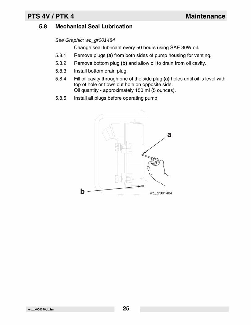
5.8 Mechanical Seal Lubrication
See Graphic: wc_gr001484
Change seal lubricant every 50 hours using SAE 30W oil.
5.8.1 Remove plugs (a) from both sides of pump housing for venting.
5.8.2 Remove bottom plug (b) and allow oil to drain from oil cavity.
5.8.3 Install bottom drain plug.
5.8.4 Fill oil cavity through one of the side plug (a) holes until oil is level withtop of hole or flows out hole on opposite side. Oil quantity - approximately 150 ml (5 ounces).
5.8.5 Install all plugs before operating pump.
a
b wc_gr001484
wc_tx000340gb.fm 25
Maintenance PTS 4V / PTK 4
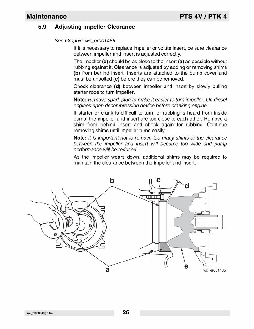
5.9 Adjusting Impeller Clearance
See Graphic: wc_gr001485
If it is necessary to replace impeller or volute insert, be sure clearancebetween impeller and insert is adjusted correctly.
The impeller (e) should be as close to the insert (a) as possible withoutrubbing against it. Clearance is adjusted by adding or removing shims(b) from behind insert. Inserts are attached to the pump cover andmust be unbolted (c) before they can be removed.
Check clearance (d) between impeller and insert by slowly pullingstarter rope to turn impeller.
Note: Remove spark plug to make it easier to turn impeller. On dieselengines open decompression device before cranking engine.
If starter or crank is difficult to turn, or rubbing is heard from insidepump, the impeller and insert are too close to each other. Remove ashim from behind insert and check again for rubbing. Continueremoving shims until impeller turns easily.
Note: It is important not to remove too many shims or the clearancebetween the impeller and insert will become too wide and pumpperformance will be reduced.
As the impeller wears down, additional shims may be required tomaintain the clearance between the impeller and insert.
wc_gr001485ea
b cd
wc_tx000340gb.fm 26

PTS 4V / PTK 4 Maintenance
5.10 Cleaning Pump
See Graphic: wc_gr001486
After pumping water containing a large amount of dirt or debris, cleanout inside of pump housing.
5.10.1 Remove drain plug (a) from pump housing and drain any water left inpump.
5.10.2 Loosen the four knobs (b) holding the pump cover and remove cover.
5.10.3 Clean out dirt and debris. Inspect impeller and volute insert for wear.
Note: Tighten cover evenly at all four corners using a wrench.
CAUTION: The impeller may develop sharp edges. Use care whencleaning around impeller to prevent getting cut.
a
b
wc_gr001486
wc_tx000340gb.fm 27

Maintenance PTS 4V / PTK 4
5.11 Storage
If pump is being stored for more than 30 days:
NEVER open priming plug, discharge plug, or cover when pump is hot.
5.11.1 Remove discharge plug from pump casing and drain out any water leftin the housing after pump has cooled.
5.11.2 Remove pump cover and clean inside of pump housing. Coat inside ofpump with a light film of oil to reduce corrosion. A spray can of oil workswell for this.
5.11.3 Tape up suction and discharge ports to prevent anything from fallinginto pump.
5.11.4 Change engine oil and follow procedures described in engine manualfor engine storage.
5.11.5 Cover pump and engine and store in a clean, dry area.
5.12 Lifting
See Graphic: wc_gr001487
To lift machine mechanically:
CAUTION: Before attempting to lift, be sure that lifting devices cansafely handle weight of machine. See Technical Data for weight ofmachine.
Attach hook, harness, or cable to machine as shown and lift asdesired.
WARNING
wc_gr001487
wc_tx000340gb.fm 28

PTS 4V / PTK 4 Maintenance
5.13 Troubleshooting
Problem / Symptom Reason / Remedy
Pump does not take in water. • Not enough priming water in housing.
• Engine speed too low. Adjust speed.
• Strainer plugged. Clean strainer.
• Suction hose damaged. Replace or repair hose.
• Air leak at suction port. Check that fittings are tight and sealing properly.
• Pump too high above water.
• Debris collecting in pump housing. Clean pump housing.
• Too much clearance between impeller and insert.
Pump takes in water, little or no discharge.
• Engine speed too low. Adjust speed.
• Suction strainer partially plugged. Clean strainer.
• Impeller worn. Adjust clearance by adding shims or replace impeller.
• Volute insert worn or damaged. Adjust clearance or replace insert.
Suction hose leaks at inlet. • Clamps are not sealing properly. Tighten, replace, or add clamp.
• Hose diameter is too large.
• Hose is damaged.
Discharge hose does not stay on coupling.
• Pressure may be too high for clamps being used. Add another clamp.
• Hose kinked or end blocked. Check hose.
Impeller does not turn; pump is hard to start.
• Impeller jammed or blocked. Open pump cover and clean dirt and debris from inside of pump housing.
• Impeller and insert binding. Adjust clearance by remov-ing shim from behind insert.
Engine does not start or stops during operation.
• Debris in pump housing, blocking impeller.
• Low oil level in engine.
• Impeller rubbing on insert.
wc_tx000340gb.fm 29

Maintenance PTS 4V / PTK 4
Noteswc_tx000340gb.fm 30


2005-CE-PTS4V-Q.fm
William Lahner Dan DomanskiVice President of Engineering Manager, Product Engineering
WACKER CORPORATIONDate / Datum / Fecha / Date
EC DECLARATION OF CONFORMITYCE-KONFORMITÄTSERKLÄRUNG
DECLARACIÓN DE CONFORMIDAD DE LA CE DÉCLARATION DE CONFORMITÉ C.E.
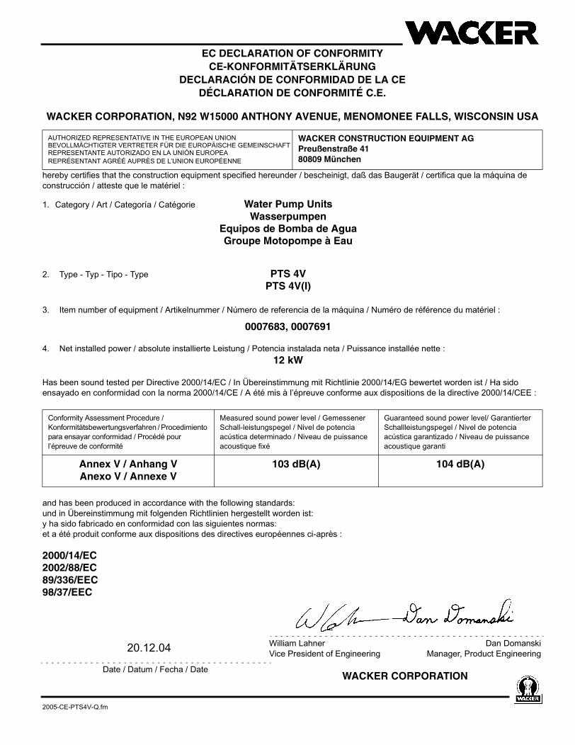
WACKER CORPORATION, N92 W15000 ANTHONY AVENUE, MENOMONEE FALLS, WISCONSIN USA
hereby certifies that the construction equipment specified hereunder / bescheinigt, daß das Baugerät / certifica que la máquina de construcción / atteste que le matériel :
1. Category / Art / Categoría / Catégorie Water Pump UnitsWasserpumpen
Equipos de Bomba de AguaGroupe Motopompe à Eau
2. Type - Typ - Tipo - Type PTS 4VPTS 4V(I)
3. Item number of equipment / Artikelnummer / Número de referencia de la máquina / Numéro de référence du matériel :
0007683, 0007691
4. Net installed power / absolute installierte Leistung / Potencia instalada neta / Puissance installée nette :12 kW
Has been sound tested per Directive 2000/14/EC / In Übereinstimmung mit Richtlinie 2000/14/EG bewertet worden ist / Ha sido ensayado en conformidad con la norma 2000/14/CE / A été mis à l’épreuve conforme aux dispositions de la directive 2000/14/CEE :
and has been produced in accordance with the following standards:und in Übereinstimmung mit folgenden Richtlinien hergestellt worden ist:y ha sido fabricado en conformidad con las siguientes normas:et a été produit conforme aux dispositions des directives européennes ci-après :
2000/14/EC2002/88/EC89/336/EEC98/37/EEC
AUTHORIZED REPRESENTATIVE IN THE EUROPEAN UNIONBEVOLLMÄCHTIGTER VERTRETER FÜR DIE EUROPÄISCHE GEMEINSCHAFTREPRESENTANTE AUTORIZADO EN LA UNIÓN EUROPEAREPRÉSENTANT AGRÉÉ AUPRÈS DE L’UNION EUROPÉENNE
WACKER CONSTRUCTION EQUIPMENT AGPreußenstraße 4180809 München
Conformity Assessment Procedure / Konformitätsbewertungsverfahren / Procedimiento para ensayar conformidad / Procédé pour l’épreuve de conformité
Measured sound power level / Gemessener Schall-leistungspegel / Nivel de potencia acústica determinado / Niveau de puissance acoustique fixé
Guaranteed sound power level/ Garantierter Schallleistungspegel / Nivel de potencia acústica garantizado / Niveau de puissance acoustique garanti
Annex V / Anhang VAnexo V / Annexe V
103 dB(A) 104 dB(A)
20.12.04

Wacker Construction Equipment AG · Preußenstraße 41 · D-80809 München · Tel.: +49-(0)89-3 54 02 - 0 · Fax: +49 - (0)89-3 54 02-3 90Wacker Corporation · P.O. Box 9007 · Menomonee Falls, WI 53052-9007 · Tel. : (262) 255-0500 · Fax: (262) 255-0550 · Tel. : (800) 770-0957Wacker Asia Pacific Operations · Skyline Tower, Suite 2303, 23/F · 39 Wang Kwong Road, Kowloon Bay, Hong Kong · Tel. +852 2406 60 32 · Fax: +852 2406 60 21