pt500 500mbps powerline adapter user guide -...
TRANSCRIPT

PT500 500Mbps Powerline Adapter
User Guide

i
PT500 500Mbps Powerline Adapter
V100R001
User Guide
202593_04
Huawei Technologies Co., Ltd. provides customers with comprehensive technical
support and service. Please feel free to contact our local office or company
headquarters.
Huawei Technologies Co., Ltd.
Address: Huawei Industrial Base
Bantian, Longgang
Shenzhen 518129
People's Republic of China
Website: http://www.huawei.com
Email: [email protected]
ii
Copyright © Huawei Technologies Co., Ltd. 2013. All rights reserved. No part of this document may be reproduced or transmitted in any form or by any means
without prior written consent of Huawei Technologies Co., Ltd.
The product described in this manual may include copyrighted software of Huawei
Technologies Co., Ltd and possible licensors. Customers shall not in any manner
reproduce, distribute, modify, decompile, disassemble, decrypt, extract, reverse engineer,
lease, assign, or sublicense the said software, unless such restrictions are prohibited by
applicable laws or such actions are approved by respective copyright holders under
licenses.
Trademarks and Permissions
、 、and are trademarks or registered trademarks of
Huawei Technologies Co., Ltd.
HDMI, the HDMI Logo, and High-Definition Multimedia Interface are trademarks
or registered trademarks of HDMI Licensing LLC in the United States and other
countries.
Other trademarks, product, service and company names mentioned are the
property of their respective owners.
Notice Some features of the product and its accessories described herein rely on the software
installed, capacities and settings of local network, and may not be activated or may be
limited by local network operators or network service providers. Thus the descriptions
herein may not exactly match the product or its accessories you purchase.
Huawei Technologies Co., Ltd reserves the right to change or modify any information or
specifications contained in this manual without prior notice or obligation.
DISCLAIMER ALL CONTENTS OF THIS MANUAL ARE PROVIDED “AS IS”. EXCEPT AS REQUIRED
BY APPLICABLE LAWS, NO WARRANTIES OF ANY KIND, EITHER EXPRESS OR

iii
IMPLIED, INCLUDING BUT NOT LIMITED TO, THE IMPLIED WARRANTIES OF
MERCHANTABILITY AND FITNESS FOR A PARTICULAR PURPOSE, ARE MADE IN
RELATION TO THE ACCURACY, RELIABILITY OR CONTENTS OF THIS MANUAL.
TO THE MAXIMUM EXTENT PERMITTED BY APPLICABLE LAW, IN NO EVENT
SHALL HUAWEI BE LIABLE FOR ANY SPECIAL, INCIDENTAL, INDIRECT, OR
CONSEQUENTIAL DAMAGES, OR LOSS OF PROFITS, BUSINESS, REVENUE, DATA,
GOODWILL SAVINGS OR ANTICIPATED SAVINGS REGARDLESS OF WHETHER
SUCH LOSSES ARE FORSEEABLE OR NOT.
THE MAXIMUM LIABILITY (THIS LIMITATION SHALL NOT APPLY TO LIABILITY FOR
PERSONAL INJURY TO THE EXTENT APPLICABLE LAW PROHIBITS SUCH A
LIMITATION) OF HUAWEI ARISING FROM THE USE OF THE PRODUCT DESCRIBED
IN THIS MANUAL SHALL BE LIMITED TO THE AMOUNT PAID BY CUSTOMERS FOR
THE PURCHASE OF THIS PRODUCT.
Import and Export Regulations
Customers shall comply with all applicable export or import laws and regulations and will
obtain all necessary governmental permits and licenses in order to export, re-export or
import the product mentioned in this manual including the software and technical data
therein.
Privacy Policy
To better understand how we protect your personal information, please see the privacy
policy at http://consumer.huawei.com/en/privacy-policy/index.htm.

iv
Contents
1 About PT500 ......................................................... 1
2 PT500 Installation ................................................. 4
3 Advanced Configuration ...................................... 6
4 Tab Pages on the PCU User Interface................ 12
5 FAQs ................................................................... 16
6 Technical Specifications .................................... 18
1
1 About PT500
Functions
The state of the art, plug and play PT500 power line adapter enables fast communication
on your existing home power line network without extra routing. With the PT500, the
power line serves as a network cable and the power socket serves as a network adapter.
You can connect to your network directly by connecting the PT500 to a power socket. The
PT500 is sleek and convenient, and can transmit data to a 300-meter distance at a rate of
200 Mbit/s on the power line network.
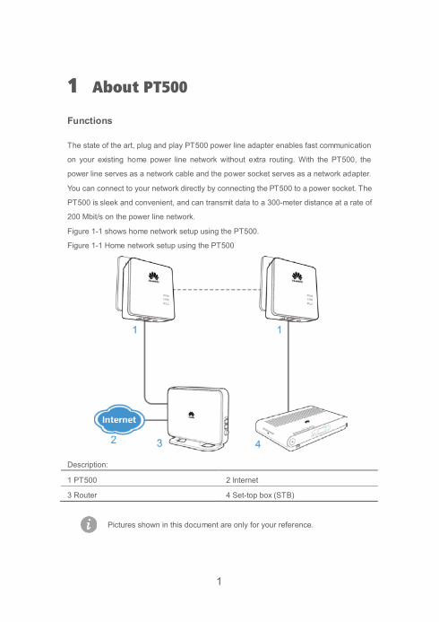
Figure 1-1 shows home network setup using the PT500.
Figure 1-1 Home network setup using the PT500
Description:
1 PT500 2 Internet
3 Router 4 Set-top box (STB)
Pictures shown in this document are only for your reference.

2
Buttons Figure 1-2 shows the buttons on the PT500 shell.
Figure 1-2 Buttons on the PT500 shell
Table 1-1 describes the buttons on the PT500.
Table 1-1 Buttons on the PT500
Button Description Pair Button Connects the PT500 to a safety network or restores the PT500
to its default settings.
Press and hold the Pair button on a PT500 (no more than 4
seconds), and repeat the operation on the other PT500 within
2 minutes. The two adapters are then connected and a LAN is
set up. After paired successfully, the two PT500 can be
plugged in or out at any time and you don’t need to pair them
again.
The PT500 is restored to its default settings when you push
and hold the Reset button for 8 seconds in running mode.
AC power plug Can be plugged into a power socket.
Network Port Connects the PT500 to a network device.
3
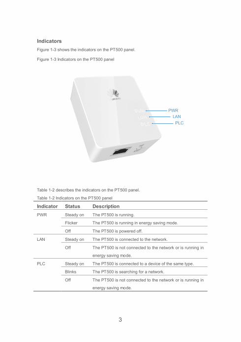
Indicators Figure 1-3 shows the indicators on the PT500 panel.
Figure 1-3 Indicators on the PT500 panel
Table 1-2 describes the indicators on the PT500 panel.
Table 1-2 Indicators on the PT500 panel
Indicator Status Description PWR Steady on The PT500 is running.
Flicker The PT500 is running in energy saving mode.
Off The PT500 is powered off.
LAN Steady on The PT500 is connected to the network.
Off The PT500 is not connected to the network or is running in
energy saving mode.
PLC Steady on The PT500 is connected to a device of the same type.
Blinks The PT500 is searching for a network.
Off The PT500 is not connected to the network or is running in
energy saving mode.

4
2 PT500 Installation Network cables and power line adapters are required if you want to use power lines to
connect terminal devices to a LAN.
Connecting the Hardware
Figure 2-1 shows how to use the power line adapter to set up a network.
Figure 2-1 Using the power line adapter to set up a network
1 . Use a network cable to connect a PT500 and network device, such as a
gateway.
2 . Connect the PT500 to a power socket. The PWR indicator turns steady on.
3 . Use another network cable to connect the other PT500 and an STB or other
terminal devices.
Connect the second PT500 to another power socket. The PWR indicator turns
steady on.
One PT500 is required to add each terminal device to the network.
Number of required PT500 adapters = Number of terminal devices + 1

5
Setting up a Network Quickly The PT500 supports the 128-bit Advanced Encryption Standard (AES). You can use the
Pair button to quickly set up a network with multiple PT500 adapters to ensure secure
data transmission.
To quickly set up a network with multiple PT500 adapters:
1 . Press and hold the Pair button on a PT500 no more than 4 seconds, and then
release it.
The PWR indicator starts to blink.
2 . Within 2 minutes, press and hold the Pair button on the other PT500 for 4
seconds, and then release it.
The PWR indicator starts to blink.
3 . View the indicator status. When all indicators turn off and then steady on, a LAN
is then set up.
4 . Press and hold the Pair button on a PT500 not connected to the LAN for 4
seconds, and then release it. Within 2 minutes, press and hold the Pair button
on any PT500 already connected to the LAN, and then release it.
The indicators on the newly connected PT500 turn off and then steady on. The
PT500 automatically restarts and is connected to the network.
A home network supports a maximum of eight PT500 adapters.
If the PLC indicator didn't blink after you press the Pair button, then please
plug the PT500 into the socket again and repeat this operation until the
indicator blinks.
If the pairing process fail for several attempts, press and hold PT500's PAIR
button more than 8 seconds until the PWR indicator turns off and then
release it. When the PWR indicator lights up again, repeat the pairing
process.

6
3 Advanced Configuration The PCU(PT500 Configuration Utility) software is used to manage the power line
adapters. This software can scan and manage all devices on a private network and
display information about devices with the same network membership key. You can go to
http://consumer.huawei.com/en to download the product configuration software.
The PCU software is required only when you use the advanced PT500
applications.
Configuring a Private Network To implement power line communication, connect at least one pair of PT500 adapters. A
power line network can be divided by network names. Each PT500 powerline adapter is
preset with a network name. PT500 powerline adapters with the same network name can
connect to each other in the same power line network. If multiple PT500 powerline
adapters are in the power line network, you can create a private network by changing the
PT500 network names. This also improves data transmission security.
After you connect them using network cables and making sure there is at least a PC in
your network, install the PT500 configuration utility (PCU) software to configure your
private network, such as home network or working network.
Figure 3-1 shows PT500’s network.
Figure 3-1 PT500’s network

7
To configure your private network:
1 . Check that the PWR indicator on the PT500 is steady on.
2 . Install PCU software.
Please run PCU software in Windows XP, Windows Vista or Windows 7.
3 . After the setup is complete, running the PT500 Configuration Utility software
, the PT500 Configuration Utility window is displayed, as shown in
Figure 3-2:
Figure 3-2 PT500 Configuration Utility window
8
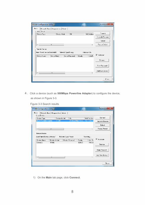
4 . Click a device (such as 500Mbps Powerline Adapter) to configure the device,
as shown in Figure 3-3.
Figure 3-3 Search results
1) On the Main tab page, click Connect.

9
The system displays the information about all devices on the LAN, such
as the device name, model, and software version in the Remote Device
area.
2) Click Device 2.
Click Enter Password to enter device’s password.
5 . Display the Network Name tab page to configure the network shown in Figure
3-4.
Figure 3-4 Network Name tab page
1) Enter a name for the private network in the Network Name text box.
2) Click Set All Devices.
All devices will restart to set up a private LAN with all device passwords
registered to the local device.
You can click Default Public Network Name to retrieve a default network
name, and then click Set All Devices to release the private LAN to set up a
public LAN.

10
Update the PT500 Firmware
1) On the Main tab page, click Upgrade Firmware.
The Enter PIB & NVM files dialog box is displayed, as shown in Figure 3-5.
Figure 3-5 Enter PIB & NVM files dialog box
2) In the Enter PIB & NVM files dialog box, click Browse to specify the path
for storing the PIB and NVM.
3) Click OK.
The files are loaded.
You can download the latest update files from the technical support Web site:
http://www.huaweidevice.com.
Restoring Default Settings
Be careful all self-defined data will be lost when you use this function.

11
To restore the PT500 to its default settings, press and hold the Pair button for 6 seconds
after it is powered on.

12
4 Tab Pages on the PCU User Interface For more information about the PCU software functions, please refer to the following
details.
Main Tab Page Main Tab Page includes two areas. The Local Device area shows the information of
device which connects your current PC and the Remote Device area show the
information of other device which in your network.
Figure 4-1 shows the Main tab page.
Figure 4-1 Main tab page
Table 4-1 describes the buttons on the Main tab page.
Table 4-1 Buttons on the Main tab page
Button Description Connect Connect to the specified remote device.
Upgrade Firmware Upgrade the firmware.
Reboot Restart a specified device.
Restore Default Restore a specified device to default settings.
Rename Rename a specified device.
13
Enter Password Set password for a specified device. When you manage a
remote power line adapter through the PCU software, you
must match the password first.
Add New Device Add a device.
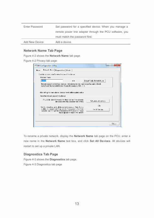
Network Name Tab Page Figure 4-2 shows the Network Name tab page.
Figure 4-2 Privacy tab page
To rename a private network, display the Network Name tab page on the PCU, enter a
new name in the Network Name text box, and click Set All Devices. All devices will
restart to set up a private LAN.
Diagnostics Tab Page Figure 4-3 shows the Diagnostics tab page.
Figure 4-3 Diagnostics tab page

14
The Diagnostics tab page displays the information about the system and remote
devices.
The System Information area displays the system information.
The Remote Device History area displays the remote device information.
About Tab Page Figure 4-4 shows the About tab page.
Figure 4-4 About tab page

15
The About tab page displays the PCU software information, such as the version and
release date.

16
5 FAQs
What Can I Do If the PWR Indicator Is Off To resolve this problem:
1 . Check that the PT500 is correctly connected to the power socket.
2 . Check whether the power socket is faulty. If yes, replace it or find another.
3 . If the PWR indicator is still off but other indicators are normal, consult your local
Internet service provider (ISP) for help.
What Can I Do If the LAN Indicator Is Off To resolve this problem:
1 . Check whether the PT500 is connected to the network port.
2 . Check whether the network adapter and driver are running properly and the
configured parameters are correct.
3 . Check whether the computer can assess the Internet after you connect it to the
LAN port of the router.
4 . Connect the PT500 to another LAN port of the router.
5 . If the LAN indicator is still off, consult your local ISP for help.
What Can I Do If the PLC Indicator Is Off If the PLC indicator didn't blink after you press the Pair button, the device may be running
in energy saving mode. Please plug the PT500 into the socket again and repeat this
operation until the indicator blinks.
What Can I Do If the PT500 Fails to Connect to the Network To resolve this problem:
1 . Plug the PT500 into the socket again.
2 . Press and hold PT500's PAIR button more than 8 seconds until the PWR
indicator turns off and then release it. When the PWR indicator lights up again,
repeat the pairing process.

17
3 . Press and hold the Pair button on a PT500 more than 1 second and less than 4
seconds, and repeat the operation on the other PT500 within 2 minutes.
4 . If the PLC indicators are still off, consult your local ISP for help.
Can I Connect Multiple PT500 Adapters A home network supports a maximum of eight PT500 adapters. To connect multiple
adapters to a home network, repeat the operation of connecting two PT500 adapters.

18
6 Technical Specifications
Item Specifications Power supply 100V ~240V AC, 50/60Hz
Power consumption < 3W
Working temperature 0℃~40℃
Working humidity 5% ~ 95% RH (non-condensing)
Dimensions (H x W x D) CN: About 71 mm × 62 mm × 48 mm
UK: About 71 mm × 62 mm × 57 mm
UL: About 71 mm × 62 mm × 49 mm
EU: About 71 mm × 62 mm × 64 mm
Weight CN: About 80 g (single piece)
UK: About 86 g (single piece)
UL: About 81 g (single piece)
EU: About 85 g (single piece)