pt pg pd - wacker neusonproducts.wackerneuson.com/manuals/repair/117617_001rep.pdf · pt / pg / pd...
TRANSCRIPT

www.wackergroup.com
Trash PumpsDewatering PumpsDiaphragm Pumps
PTPGPD
REPAIR MANUAL
0117617 001
0999 en
0 1 1 7 6 1 7

PT / PG / PD REPAIR FOREWORD
Operating / Parts Information
You must be familiar with the operation of this machine before you attempt to troubleshoot or make any repairsto it. Basic operating and maintenance procedures are described in the operator’s / parts manual supplied withthe machine. The operator’s / parts manual should be kept with the machine. Use it to order replacement partswhen needed. If this manual becomes lost, please contact WACKER Corporation to order a replacement.
Damage caused by misuse or neglect of the unit should be brought to the attention of the operator, to preventsimilar occurrences from happening in the future.
This manual provides information and procedures to safely repair and maintain this WACKER model. For yourown safety and protection from injury, carefully read, understand and observe the safety instructions describedin this manual. THE INFORMATION CONTAINED IN THIS MANUAL WAS BASED ON MACHINES INPRODUCTION PRIOR TO THE TIME OF PUBLICATION OF THIS MANUAL. WACKER CORPORATIONRESERVES THE RIGHT TO CHANGE ANY PORTION OF THIS INFORMATION WITHOUT NOTICE.
i
Information Contained in This Manual
This repair manual is intended to provide information and procedures to safely operate, maintain and servicethe WACKER Model PT, PG and PD Series Pumps. Step-by-step instructions and illustrations are providedwhenever possible. Refer to this repair manual and the owner’s manual supplied with the unit wheneverservicing this machine.
It is the responsibility of the individual servicing this equipment to familiarize himself with its operatingcharacteristics and service procedures before attempting any repairs. Repairs caused by misuse or neglectof the unit should be brought to the attention of the operator, to prevent similar failures from happening in thefuture.
This manual covers pump modelsPT, PG & PD
Refer to the following pages for machine serial numbers oritem numbers.

FOREWORD PT / PG / PD REPAIR
Serial Number
My machine’s numbers are:
RevisionItem NumberModel number
MENOMONEE FALLS, WI USA 53051
Serial Number
Manuf.Yr.
m3/hrm ft
Model
Item Number
dB(A) MADE IN USA
kWlbskg
Rev.
gpm
hp
1111
73
PT3APT3APT3APT3APT3A
00067290006729000672900067290006729 101101101101101 50101015010101501010150101015010101
Nameplate
A nameplate listing the Model Number, Item Number, Revision, and Serial Number is attached to each unit.Please record the information found on this plate so it will be available should the nameplate become lost ordamaged. When ordering parts or requesting service information, you will always be asked to specifythe model, item number, revision number, and serial number of the unit.
1027SD33
1011SD33
1027SD32
ii

PT / PG / PD REPAIR FOREWORD
Item Number Model EngineMake Model
4185 PT 4B Briggs 3264324186 PT 2B Briggs 1322324187 PT 2R Robin EY 18-3W4188 PT 3B Briggs 1954324189 PT 3R Robin EY 27W
4193 PD 3B Briggs 802524200 PT 4H Hatz E 7854201 PT 2F Farymann 15A4304202 PT 3H Hatz E 795000 PT 2B Briggs 132232
5001 PT 2R Robin EY 18-3W5002 PT 2F Farymann 15A4305003 PT 3B Briggs 1954325004 PT 3R Robin EY 27W5005 PT 3H Hatz E 79
5006 PT 4B Briggs 3264325007 PT 4H Hatz E 7855014 PG 2 Honda G 1505015 PG 3 Honda G 25016 PG 2 Honda G150
5016 01151 & up PG 2 Honda GX 1105017 PG 3 Honda G 2005017 01151 & up PG 3 Honda GX 1405018 PD 3B Briggs 810005018 01049 & up PD 3B Briggs 80252
5022 PT 2R Robin WI-1855023 PT 2R Robin WI-1855029 PT 3H Hatz E 795034 PTS 3H Hatz E 795035 PTS 3H Hatz E 79
5036 PT 4H Hatz E 7855037 PTS 4H Hatz E 7855037 01017 & up PTS 4H Hatz E 7865038 PTS 4H Hatz E 7855038 01009 & up PTS 4H Hatz E 786
5039 PT 4B Briggs 3264325040 PTS 4H Hatz E 7855043 PT 3R Robin EY 27W5044 PT 3B Briggs 1954325045 PTS 3H Hatz E 79
5046 PT 3R Robin WI-1855047 PT 2F Farymann 15A4305048 PT 2B Briggs 1322325057 PT 2H Hatz E 6735058 PT 2H Hatz E 673
5059 PT 2H Hatz E 6735061 PD 3H Hatz E 6735063 PD 3H Hatz E 6735066 PT 2A Honda GX 1405067 PT 2A Honda GX 140
5068 PT 3A Honda G 3005068 01581 & up PT 3A Honda GX 2405069 PT 3A Honda G 3005069 01026 & up PT 3A Honda GX 2405794 PD 2B Briggs 80252
5795 PD 2B Briggs 802525825 PD 3B Briggs 1322125826 PD 3B Briggs 1322126216 PD 3A Honda GX 1106217 PD 3A Honda GX 110
6246 PT 3R Robin WI-2806247 PT 3R Robin WI-2806248 PT 3R Robin WI-2806292 PT 2B Briggs 1322326294 PT 2B Briggs 132232
6303 PT 2R Robin WI-1856532 PT 2A Honda GX 1406533 PT 2A Honda GX 1406534 PT 2B Briggs 1322326535 PT 2B Briggs 132232
6536 PT 2R Robin WI-1856537 PT 2R Robin WI-1856557 PT 4B Briggs 3264326558 PT 4H Hatz E 7856574 PT 3A Honda GX 240
6575 PT 3B Briggs 1954326576 PT 3B Briggs 1954326577 PT 3H Hatz ES 796578 PT 3R Robin WI-2806579 PT 3R Robin WI-280
6580 PT 2H Hatz 673 LS6586 PT 3V Vanguard 1614326587 PT 3V Vanguard 1614326720 PT 2A Honda GX 1606721 PT 2A Honda GX 160
6722 PT 2B Briggs 1322326724 PT 2R Robin WI-1856725 PT 2R Robin WI-1856726 PT 2R Robin WI-1856729 PT 3A Honda GX 240
6730 PT 3A Honda GX 2406731 PT 3B Briggs 1954326732 PT 3B Briggs 1954326733 PT 3H Hatz ES 796734 PT 3R Robin WI-280
6735 PT 3R Robin WI-2806772 PT 2R Robin WI-1856788 PT 2R Robin W01-1706789 PT 2R Robin W01-1706801 PD 3B Briggs 133412
7116 PT 2Y Yanmar L48AE-D7117 PT 2Y Yanmar L48AE-D7118 PT 3Y Yanmar L70AE-D7119 PT 3Y Yanmar L70AE-D7120 PD 2B Briggs 80212
7121 PD 2B Briggs 802127160 PT 2R Robin W01-1707163 PT 3A Honda GX2407171 PT 3V Vanguard 1854327610 PDT 2A Honda GX120
Item Number Model EngineMake Model
Pump models and engine options are listed below in item number sequence.
Pump Model by Item Number
iii

FOREWORD PT / PG / PD REPAIR
Item Number Model EngineMake Model
7611 PDT2A(I) Honda GX1207614 PDT 3A Honda GX1207615 PDT3A(I) Honda GX1207616 PDT3A Honda GX1207619 PDT3 (I) n/a n/a
7624 PDI 2A Honda GX1207625 PDI2A(I) Honda GX1207628 PDI 3A Honda GX1207629 PDI3A(I) Honda GX1207633 PDT 2 n/a n/a
7658 PG 2 Honda GX1207659 PG 3 Honda GX1607683 PTS 4V Vanguard 3034477691 PTS4V(I) Vanguard 3034478023 PT3V(I) Vanguard 185432
Item Number Model EngineMake Model
iv

1-1
PT / PG / PD REPAIR GENERAL 1
Table of Contents
1.1 Safety Notes ........................................................................................... 1-21.2 Laws Pertaining to Spark Arresters ......................................................... 1-21.3 Tools ....................................................................................................... 1-21.4 Reference Numbers ( ) ........................................................................... 1-21.5 Ordering Parts ......................................................................................... 1-21.6 Application .............................................................................................. 1-31.7 Operating Safety ..................................................................................... 1-41.8 Operator Safety while using Internal Combustion Engines ...................... 1-41.9 Service Safety ......................................................................................... 1-51.10 Technical Data (PT2) .............................................................................. 1-61.11 Technical Data (PT3) .............................................................................. 1-81.12 Technical Data (PTS4) .......................................................................... 1-101.13 Technical Data (PG2 / PG3).................................................................. 1-121.14 Technical Data (PD2 / PD3) .................................................................. 1-141.15 Performance Curves ............................................................................. 1-16
1-2
1 GENERAL PT / PG / PD REPAIR
1.4 Reference Numbers ( )
Repair procedures contain reference numbers enclosedin parentheses ( ). These numbers refer to the itemnumbers shown on the appropriate assembly drawingsand other detailed drawings. They are included to aid themechanic in identifying parts and assembling compo-nents.
1.3 Tools
Since all possible problems encountered while repairingthe equipment cannot be anticipated, it is up to themechanic to use common sense and good judgment intool selection.
The use of any special tools is recommended only forthose operations where the use of conventional toolsproves inadequate.
Before substituting another tool or procedure, you shouldbe satisfied that neither personal injury nor damage to thecomponent will result.
1.5 Ordering Parts
The repair procedures contained in this manual do notinclude part numbers. For parts replacement informa-tion, refer to the Parts Manual originally supplied with theunit.
If the original Parts Manual has been lost, a replacementmanual may be ordered from WACKER Corporation.When ordering a replacement Parts Manual, please listmodel number, item number, revision number, and serialnumber of machine.
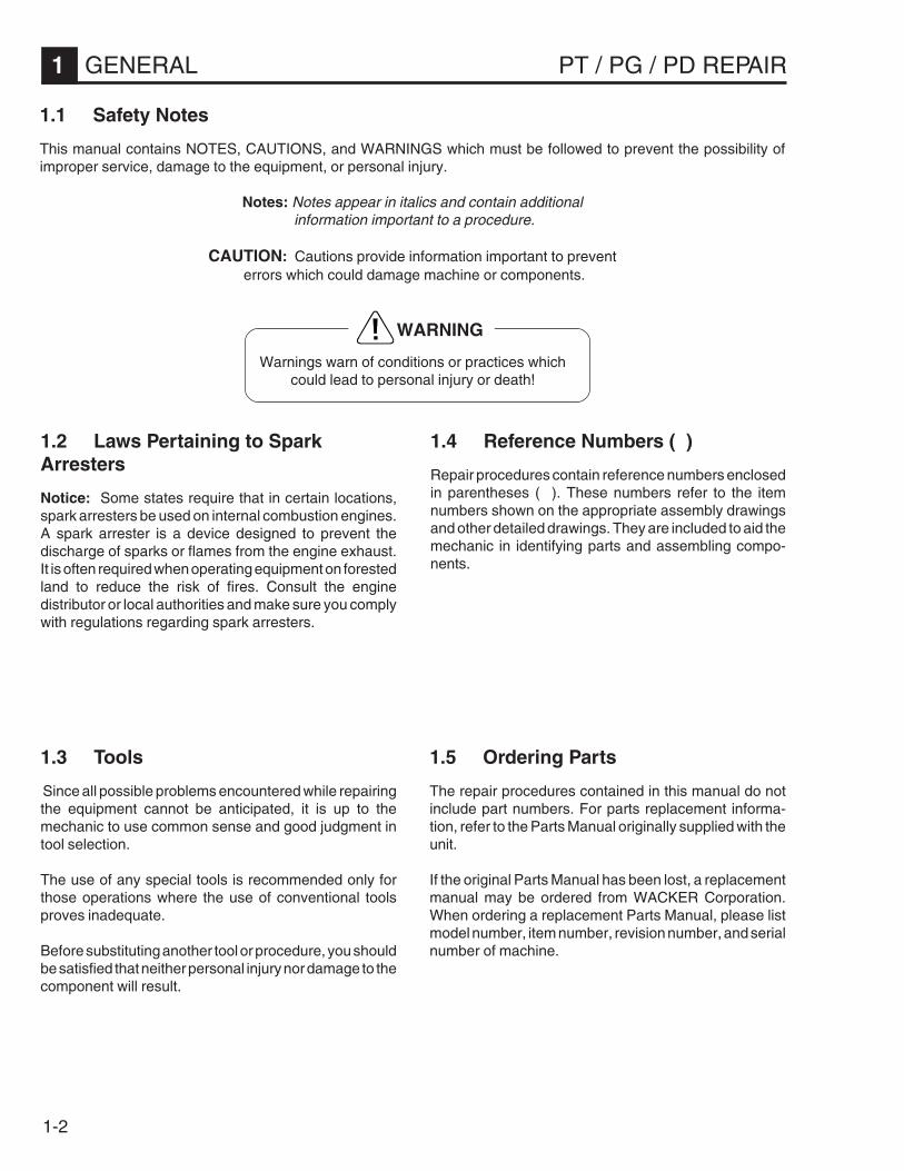
1.1 Safety Notes
This manual contains NOTES, CAUTIONS, and WARNINGS which must be followed to prevent the possibility ofimproper service, damage to the equipment, or personal injury.
Notes: Notes appear in italics and contain additional information important to a procedure.
CAUTION: Cautions provide information important to prevent errors which could damage machine or components.
Warnings warn of conditions or practices whichcould lead to personal injury or death!
WARNING
1.2 Laws Pertaining to SparkArresters
Notice: Some states require that in certain locations,spark arresters be used on internal combustion engines.A spark arrester is a device designed to prevent thedischarge of sparks or flames from the engine exhaust.It is often required when operating equipment on forestedland to reduce the risk of fires. Consult the enginedistributor or local authorities and make sure you complywith regulations regarding spark arresters.

1-3
PT / PG / PD REPAIR GENERAL 1
1.6 Application
PT Series
The WACKER PT Series Trash Pumps are high capac-ity, centrifugal pumps designed for pumping wastewater.Their heavy duty construction allows them to handle solidparticles and debris suspended in the water. Refer to“Technical Data” for maximum solid size.
Close internal tolerances provide suction lifts up to 25'(7.6m) and high discharge capacities.
These pumps are desirable in applications where largevolumes of water must be pumped or high dischargepressures are required.
CAUTION: These pumps are not intended for thepumping of heavy sludges or slurries, mud, corrosive orvolatile liquids. DO NOT pump gasoline, diesel fuel, oilor corrosive chemicals.
PG Series
The WACKER PG Series Dewatering Pumps are highcapacity, centrifugal pumps similar in operation to the PTSeries. The centrifugal design gives them the same highperformance characteristics found in the PT Pumps.
The PG Pump can handle small particles up to 0.25"(6.5mm) in diameter. They are not designed to handlelarge solids or debris particles which may occur in certainapplications. Refer to “Technical Data” for maximumsolid size.
These pumps should only be used in applications whererelatively clean water is being pumped. Pumping volumeis less than similar size PT Pumps.
CAUTION: These pumps are not intended for thepumping of heavy sludges or slurries, mud, corrosive orvolatile liquids. DO NOT pump gasoline, diesel fuel, oilor corrosive chemicals.
PD Series
The WACKER PD Series Diaphragm Pumps are ideal forpumping seepage water, mud and slurries from excava-tions, trenches, industrial sumps, septic tanks or holdingponds. Their heavy duty construction allows them tohandle solid particles and debris suspended in the water.Refer to “Technical Data” for maximum solid size.
The PD diaphragm design, while capable of providingsuction lifts up to 25' (7.6m), cannot achieve the highdischarge capacities and pressures produced by PT andPG Series centrifugal type pumps. Discharge head islimited to 25' (7.6m).
CAUTION: DO NOT pump gasoline, diesel fuel, oil orother volatile or corrosive chemicals.
1027SD33 1011SD33
1027SD32
1-4
1 GENERAL PT / PG / PD REPAIR
WARNING
DO NOT spill fuel when refueling engine.
DO NOT operate near open flames.
ALWAYS refill fuel tank in well-ventilated area.
ALWAYS replace fuel tank cap after refueling.
DO NOT smoke while operating pump.
DO NOT smoke when refueling engine.
DO NOT refuel hot or running engine.
DO NOT refuel engine near open flame.
1.8 Operator Safety while using Internal Combustion Engines
Internal combustion engines present special hazards during operation and fueling! Failure to follow the safetyguidelines described below could result in severe injury or death.
1.7 Operating Safety
Familiarity and proper training are required for the safe operation of equipment! Equipment operated improperly or byuntrained personnel can be dangerous! Read the operating instructions contained in both this manual and the enginemanual and familiarize yourself with the location and proper use of all controls.
WARNING
NEVER allow improperly trained people to operatethis equipment. People operating this equipmentmust be familiar with the potential risks and haz-ards associated with it.
NEVER touch engine or muffler while pump isoperating or immediately after it has been turnedoff. These areas get hot and may cause burns.
NEVER use accessories or attachments which arenot recommended by WACKER for this equip-ment. Damage to equipment and/or injury to usermay result.
NEVER pump volatile, flammable or low flash pointfluids. These fluids could ignite or explode.
NEVER pump corrosive chemicals or water con-taining toxic substances. These fluids could createserious health and environmental hazards. Con-tact local authorities for assistance.
NEVER open priming plug when pump is hot.Never loosen or remove inlet or discharge hosefittings when pump is hot. Hot water inside couldbe pressurized much like the radiator on an auto-mobile. Allow pump to cool to the touch beforeloosening plug and before loosening or removinginlet or discharge hose fittings.
NEVER open pump housing cover while pump isoperating or start pump with the cover off. Therotating impeller inside the pump can cut or severobjects caught in it.
NEVER block or restrict flow from inlet line ordischarge line. Remove kinks from discharge linebefore starting pump. Operation with a blockedinlet line or discharge line can cause water insidepump to overheat.
ALWAYS read, understand, and follow proce-dures in Operator’s Manual before attempting tooperate equipment.
ALWAYS be sure operator is familiar with propersafety precautions and operation techniques be-fore using pump.
ALWAYS be sure pump is on a firm, level surfaceand will not tip, roll, slide, or fall while operating.
ALWAYS close fuel valve on engines equipped withone, when pump is not being operated.
ALWAYS store equipment properly when it is notbeing used. Equipment should be stored in a clean,dry location out of the reach of children.

1-5
PT / PG / PD REPAIR GENERAL 1
1.9 Service Safety
Poorly maintained equipment can become a safety hazard! In order for the equipment to operate safely and properlyover a long period of time, periodic maintenance and occasional repairs are necessary.
WARNING
DO NOT attempt to clean or service pump while it isrunning. Rotating parts can cause severe injury.
DO NOTDO NOTDO NOTDO NOTDO NOT crank a flooded engine with the sparkplug removed on gasoline-powered engines.Fuel trapped in the cylinder will squirt out thespark plug opening.
DO NOTDO NOTDO NOTDO NOTDO NOT test for spark on gasoline-poweredengines, if engine is flooded or the smell ofgasoline is present. A stray spark could ignitefumes.
DO NOTDO NOTDO NOTDO NOTDO NOT use gasoline or other types of fuels orflammable solvents to clean parts, especially inenclosed areas. Fumes from fuels and solventscan accumulate and become explosive.
ALWAYS operate pump with all safety devicesand guards in place and in working order.
ALWAYS keep area around muffler free of debris suchas leaves, paper, cartons, etc. A hot muffler couldignite them, starting a fire.
ALWAYSALWAYSALWAYSALWAYSALWAYS replace worn or damaged componentswith spare parts designed and recommended byWACKER for servicing this machine.
ALWAYS remove or disconnect spark plug on pumpsequipped with gasoline engines, before servicing pump,to avoid accidental start-up.
ALWAYS handle impeller carefully. The impeller candevelop sharp edges which can cut.
1-6
1 GENERAL PT / PG / PD REPAIR
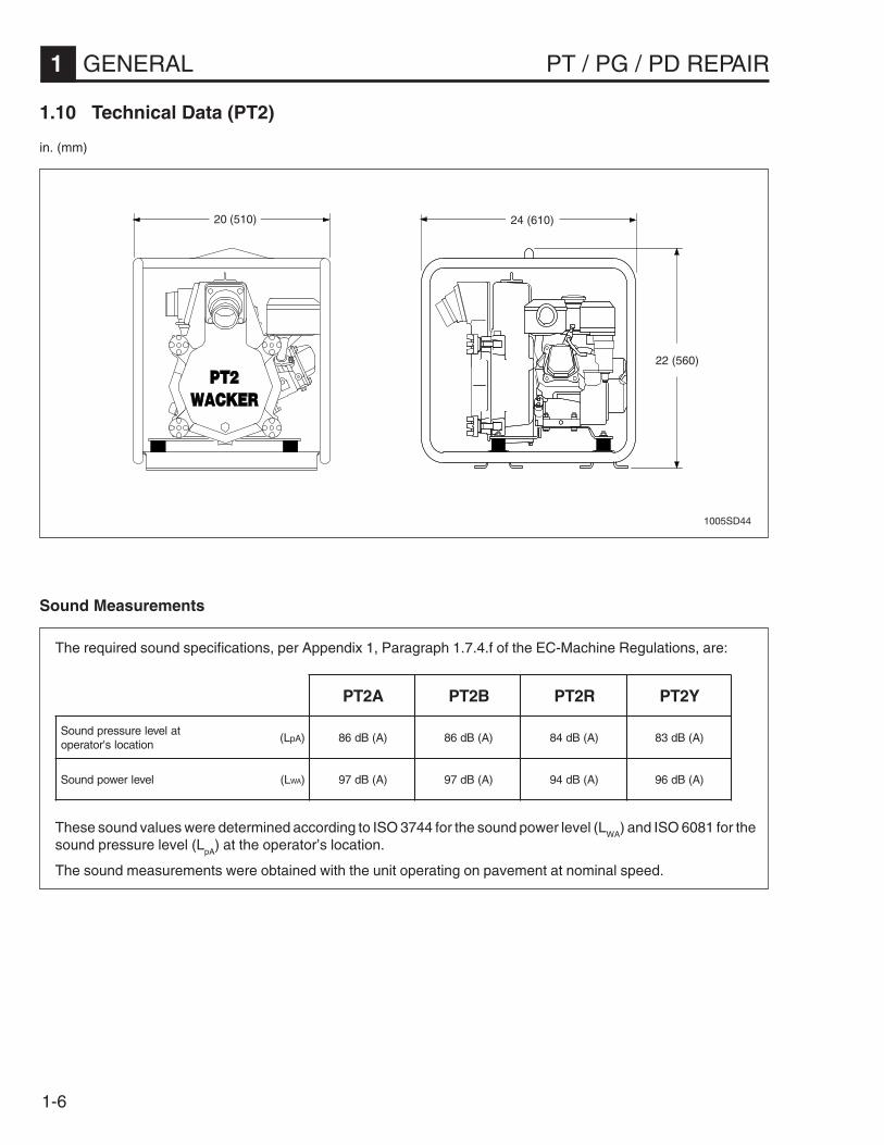
1.10 Technical Data (PT2)
in. (mm)
1005SD44
22 (560)
24 (610)20 (510)
The required sound specifications, per Appendix 1, Paragraph 1.7.4.f of the EC-Machine Regulations, are:
These sound values were determined according to ISO 3744 for the sound power level (LWA
) and ISO 6081 for thesound pressure level (L
pA) at the operator’s location.
The sound measurements were obtained with the unit operating on pavement at nominal speed.
Sound Measurements
A2TP B2TP R2TP Y2TP
talevelerusserpdnuoSnoitacols'rotarepo
L( Ap ) )A(Bd68 )A(Bd68 )A(Bd48 )A(Bd38
levelrewopdnuoS L( AW ) )A(Bd79 )A(Bd79 )A(Bd49 )A(Bd69

1-7
PT / PG / PD REPAIR GENERAL 1
1.10 Technical Data (PT2) cont.
enignE A2TP B2TP R2TP Y2TP
ekaMenignE adnoH sggirB niboR ramnaY
ledoMenignE XQ1K061XG 232331,232231 071-1OW D-EA84L
rewoPdetaR )Wk(pH )1.4(5.5 )7.3(0.5 )7.3(0.5 )7.3(0.5
gulPkrapS epytSE6RPB)KGN(CD7RWHCSOB
NOIPMAHC8JCR
roSH6B)KGN(C68LNOIPMAHC
—
paGedortcelE )mm(.ni130.0–820.0
)8.0–7.0()67.0(030.0
820.0–420.0)7.0–6.0(
—
daollluf-deepSenignE mpr 001±0053 001±0053 002±0053 001±0043
eldi-deepSenignE mpr 001±0061 001±0061 001±0061 001±0061
renaelCriA epyt tnemelelauDrepap,epytyrD
maof/wtnemelerenaelcerp
tnemelelauDrepap,epytyrD
maof/wtnemelerenaelcerp
noitacirbuLenignEedargliossalcecivres
03W01EASCS,DS,ES,FS
03W01EASCS,DS,ES,FS
03W01EASCS,DS,ES,FS
03W01EAS04W02EAS
yticapaCliOenignE )lm(.zo )006(02 )006(02 )056(12 )008(72
leuF epytdedaelnUralugeR
enilosaG-leseiD2.oN
54>enatec
yticapaCknaTleuF )l(.stq )8.3(0.4 )8.2(0.3 )6.3(8.3 )5.2(6.2
pmuP
thgieW )gk(.sbl )16(431 )06(331 )16(431 )66(541
tfiLnoitcuS.xaM* )m(.tf )5.7(52* )5.7(52* )5.7(52* )5.7(52*
daeHlatoT.xaM )m(.tf )03(001 )03(001 )03(001 )72(98
noitacirbuLlaeSlacinahceMedarglio)lm(.zo
03EAS)021(4.xorppA
03EAS)021(4.xorppA
03EAS)021(4.xorppA
03EAS)021(4.xorppA
.aiDegrahcsiD/noitcuS )mm(.ni )05(2 )05(2 )05(2 )05(2
eziSdiloS.xaM )mm(ni )52(1 )52(1 )52(1 )52(1
* Based on pump operating at sea level. Maximum suction lift will be less at higher altitudes.

1-8
1 GENERAL PT / PG / PD REPAIR
1.11 Technical Data (PT3)
in. (mm)
1007SD50
��������
25 (635)
31 (790)20 (510)
The required sound specifications, per Appendix 1, Paragraph 1.7.4.f of the EC-Machine Regulations, are:
These sound values were determined according to ISO 3744 for the sound power level (LWA
) and ISO 6081 for thesound pressure level (L
pA) at the operator’s location.
The sound measurements were obtained with the unit operating on pavement at nominal speed.
Sound Measurements
A3TP V3TP Y3TP
talevelerusserpdnuoSnoitacols'rotarepo
L( Ap ) )A(Bd68
levelrewopdnuoS L( AW ) )A(Bd79

1-9
PT / PG / PD REPAIR GENERAL 1
1.11 Technical Data (PT3) cont.
enignE A3TP V3TP Y3TP
ekaMenignE adnoH draugnaV ramnaY
ledoMenignE AQ1K042XG 234581 D-EA07L
rewoPdetaR )Wk(pH )0.6(0.8 )0.7(0.9 )0.5(0.7
gulPkrapS epytSE6RPB)kGN(CD7RWHCSOB
NOIPMAHCCY21CR
—
paGedortcelE )mm(.ni130.0–820.0
)8.0–7.0()67.0(030.0 —
daollluf-deepSenignE mpr 001±0053 001±0053 001±0043
eldi-deepSenignE mpr 001±0061 001±0061 001±0061
renaelCriA epyt tnemelelauD tnemelelauDrepap,epytyrD
maof/wtnemelerenaelcerp
noitacirbuLenignEedargliossalcecivres
03W01EASCS,DS,ES,FS
03W01EASCS,DS,ES,FS
03W01EAS04W02EAS
yticapaCliOenignE )lm(.zo )0011(73 )0021(14 )0011(73
leuF epytdedaelnUralugeR
enilosaGdedaelnUralugeR
enilosaG-leseiD2.oN
54>enatec
yticapaCknaTleuF )l(.stq )1.6(4.6 )0.6(3.6 )5.3(6.3
pmuP
thgieW )gk(.sbl )47(461 )08(771 )58(781
tfiLnoitcuS.xaM* )m(.tf )5.7(52* )5.7(52* )5.7(52*
daeHlatoT.xaM )m(.tf )92(59 )92(59 )52(28
noitacirbuLlaeSlacinahceMedarglio.zo
03EAS)021(4.xorppA
03EAS)021(4.xorppA
03EAS)021(4.xorppA
.aiDegrahcsiD/noitcuS )mm(.ni )57(3 )57(3 )57(3
eziSdiloS.xaM )mm(.ni )83(5.1 )83(5.1 )83(5.1
* Based on pump operating at sea level. Maximum suction lift will be less at higher altitudes.

1-10
1 GENERAL PT / PG / PD REPAIR
1.12 Technical Data (PTS4)
in. (mm)
36 (915)
35 (890)
35 (890)
1020SD70
The required sound specifications, per Appendix 1, Paragraph 1.7.4.f of the EC-Machine Regulations, are:
These sound values were determined according to ISO 3744 for the sound power level (LWA
) and ISO 6081 for thesound pressure level (L
pA) at the operator’s location.
The sound measurements were obtained with the unit operating on pavement at nominal speed.
Sound Measurements
V4STP
talevelerusserpdnuoSnoitacols'rotarepo
L( Ap ) —
levelrewopdnuoS L( AW ) )A(Bd301

1-11
PT / PG / PD REPAIR GENERAL 1
enignE V4STP
ekaMenignE draugnaV
ledoMenignE 744303
rewoPdetaR )Wk(pH )21(61
gulPkrapS epyt CY21CRnoipmahC
paGedortcelE )mm(.ni )67.0(030.0
daollluf-deepSenignE mpr 001±0063
renaelCriA epyt tnemelelauD
noitacirbuLenignEedargliossalcecivres
03W01EAS ⇓ W03EASro)C°5(F°04 ⇑ )C°5(F°04GS,ES,FS
yticapaCliOenignE )lm(.zo )0041(84
leuF epyt enilosaGdedaelnUralugeR
yticapaCknaTleuF )l(.stq )41(7.3
yrettaBACC/tloVezis/ruoh-pma
032/21FN22/23
pmuP
thgieW )gk(.sbl )361(063
tfiLnoitcuS.xaM* )m(.tf )5.7(52*
daeHlatoT.xaM )m(.tf )23(601
noitacirbuLlaeSlacinahceMedarglio)lm(.zo
03EAS)051(5
egrahcsiD/noitcuSretemaiD
)mm(.ni )001(4
eziSdiloS.xaM )mm(.ni )05(2
1.12 Technical Data (PTS4) cont.
* Based on pump operating at sea level. Maximum suction lift will be less at higher altitudes.

1-12
1 GENERAL PT / PG / PD REPAIR
1.13 Technical Data (PG2 / PG3)
in. (mm)
1019SD92
A B
C
Sound Measurements
The required sound specifications, per Appendix 1, Paragraph 1.7.4.f of the EC-Machine Regulations, are:
These sound values were determined according to ISO 3744 for the sound power level (LWA
) and ISO 6081for the sound pressure level (LpA) at the operator’s location.
The sound and vibration specifications were obtained with the unit operating on pavement at nominal enginespeed.
2GP 3GP
talevelerusserpdnuoSnoitacols'rotarepo
L( Ap ) )A(Bd48 )A(Bd78
levelrewopdnuoS L( AW ) )A(Bd49 )A(Bd79
2GP 3GP
A )mm(.ni )053(7.31 )573(7.41
B )mm(.ni )074(5.81 )505(0.02
C )mm(.ni )063(0.41 )054(7.71

1-13
PT / PG / PD REPAIR GENERAL 1
1.13 Technical Data (PG2 / PG3) cont.
enignE 2GP 3GP
ekaMenignE adnoH adnoH
ledoMenignE 4B1W021XG 2C1W061XG
rewoPdetaR )Wk(pH )0.3(0.4 )1.4(5.5
gulPkrapS epyt SE6RPB)KGN( SE6RPB)KGN(
paGedortcelE )mm(.ni130.0–820.0
)8.0–7.0(130.0–820.0
)8.0–7.0(
daollluf-deepSenignE mpr 001±0003 001±0003
eldi-deepSenignE mpr 001±0061 001±0061
renaelCriA epyt tnemeleelgniS tnemeleelgniS
noitacirbuLenignEedargliossalcecivres
03W01EASGS,FS
03W01EASGS,FS
yticapaCliOenignE )lm(.zo )006(02 )006(02
leuF epyt enilosaGdedaelnUralugeR enilosaGdedaelnUralugeR
yticapaCknaTleuF )l(.stq )5.2(6.2 )8.3(0.4
ecnaraelCevlaV )mm(.ni)51.0(600.0:telnI)02.0(800.0:teltuO
)51.0(600.0:telnI)02.0(800.0:teltuO
pmuP
thgieW )gk(.sbl )72(06 )33(37
tfiLnoitcuS.xaM* )m(.tf )5.7(52 )5.7(52
daeHlatoT.xaM )m(.tf )03(89 )03(89
.aiDegrahcsiD/noitcuS )mm(.ni )05(2 )05(2
eziSdiloS.xaM )mm(.ni )6(52.0 )6(52.0
* Based on pump operating at sea level. Maximum suction lift will be less at higher altitudes.

1-14
1 GENERAL PT / PG / PD REPAIR
1.14 Technical Data (PD2 / PD3)in. (mm)
PDT 2A/3A
PDI 2A/3A
PDT2A - 22.5 (572)PDT3A - 24 (610)
PDT2A - 40 (1015)PDT3A - 40 (1015)
PDI2A - 17.5 (445)PDI3A - 17.5 (445)
PDI2A - 40 (1015)PDI3A - 40 (1015)
PDI2A - 22.5 (572)PDI3A - 24 (610)
1010SD43
1017SD02
PDT2A - 25 (635)PDT3A - 29.5 (750)
The required sound specifications, per Appendix 1, Paragraph 1.7.4.f of the EC-Machine Regulations, are:
These sound values were determined according to ISO 3744 for the sound power level (LWA
) and ISO 6081 for thesound pressure level (LpA) at the operator’s location.
The sound measurements were obtained with the unit operating on pavement at nominal speed.
Sound Measurements
2DP 3DP
talevelerusserpdnuoSnoitacols'rotarepo
L( Ap ) )A(Bd28
levelrewopdnuoS L( AW ) )A(Bd29

1-15
PT / PG / PD REPAIR GENERAL 1
1.14 Technical Data (PD2 / PD3) cont.
enignE A2DP A3DP
ekaMenignE adnoH
ledoMenignE XQ1K021XG
rewoPdetaR )Wk(pH )0.3(0.4
gulPkrapS epytSE6RPB)KGN(CD7RWHCSOB
paGedortcelE )mm(.ni130.0–820.0
)8.0–7.0(
daollluf-deepSenignE mpr 001±0003
eldi-deepSenignE mpr 001±0061
renaelCriA epyt tnemelelauD
noitacirbuLenignEedargliossalcecivres
03W01EASCS,DS,ES,FS
yticapaCliOenignE )lm(.zo )006(02
leuF epyt enilosaGdedaelnUralugeR
yticapaCknaTleuF )l(.stq )5.2(6.2
pmuP A2IDP/TDP A3IDP/TDP
thgieW )gk(.sbl )25(411 )36(831
tfiLnoitcuS.xaM* )m(.tf )5.7(52 )5.7(52
daeHegrahcsiD.xaM )m(.tf )5.7(52 )5.7(52
daeHlatoT.xaM )m(.tf )51(05 )51(05
egrahcsiD.xaM )h³m(mpg )11(05 02(88
noitacirbuLesaCraeGedarglio)lm(.zo
03EAS)0001(23
03EAS)0001(23
.aiDegrahcsiD/noitcuS )mm(.ni )05(2 )57(3
eziSdiloS.xaM )mm(.ni )03(52.1 )54(57.1
* Based on pump operating at sea level. Maximum suction lift will be less at higher altitudes.

1-16
1 GENERAL PT / PG / PD REPAIR
1.15 Performance Curves
These values are average values based on pumps operating at sea level. To determine accurate values for pumpcapacity, altitude and other factors affecting suction lift and discharge head must be considered. Consult WACKERCorporation for additional information.
PT Pumps
Top curve - Gasoline powered pumpsBottom curve - Diesel powered pumps
On the PT Series, diesel powered pumps operate at lower engine speeds than those driven by gasoline poweredengines. This reduces the amount of water which they can displace and also lowers the discharge pressure, resultingin a slightly lower performance curve.
TO READ PUMP CAPACITY: first, determine the total head being applied to the pump and read across to the curverepresenting the correct engine type and suction lift.
Note: Each leg on the curve indicates a different suction lift.
After locating this point on the curve, read down to find the approximate capacity for the pump.
� � � �� � � � � �
� � � � � �
�
�
�
� �
� �
� �
� �
� �
� �
� �
� � � � � � � � � � �
� � � � � � � � � � � � � � � � � � � � � � � ��
� � � � � � � � �
� � � � � � � � � � � � � � � � � � � � � � � � � � � � � � � �
� � � � � � � � � � � � � � � �
�� � � ��
� � �
� � � � � � � � � �
� � � �
� � �
� � �
� � �
� � �
� � � �
� � � �
� � � �
� � � �
� � � �
� � � �
� � � �
� � � �
� � � �
� � � �
� � � �� � � � �
� � � �
� � � �
� � �
� � � �
� � � �
PT2
1033SD95

1-17
PT / PG / PD REPAIR GENERAL 1
1.15 Performance Curves (cont.)
� � � �� � � � � �
� � � � � �
�
�
�
� �
� �
� �
� �
� �
� �
� �
� � � � � � � � �
� � � � � � � � � � � � � � � � � � � � � � � ��
� � � � � � � � ��� � � ��
� � �
� � �
� � �
� � �
� � �
� � � �
� � � �
� � � �
� � � �
� � � �
� � � �
� � � �
� � � �
� � � �
� � � �
� � � � � � � �
� � � � � � � � � � � � � � � � � � � � � � � � �
� � � � � � � � � � � � � �
� � � � � � � � � � � � � � � � � � � � � � � �
� � � �
� � � �
� � � � �
� � � �
� � � �
� � �
� � � �
� � � �
PT3
PTS4
�� � � ��
� � � �� � � � � �
� � � � � �
�
�
�
� �
� �
� �
� �
� �
� �
� �
� � �
� � � � � �
� � �
� � �
� � �
� � �
� � � �
� � � �
� � � �
� � � �
� � � �
� � � �
� � � �
� � � �
� � � � � � � � � � � � � � � �� � � � � � � � � � � � �
� � � � � � � � � � � � � � � � � � � � �
� �
� � � ! � "� " � � �
� � � � � � � � � � � � � � � � � �
� � � ! � "� " � � �
� � � ! � "� " � � �
� � ! � "� " � � �
1033SD97
1033SD96
1-18
1 GENERAL PT / PG / PD REPAIR
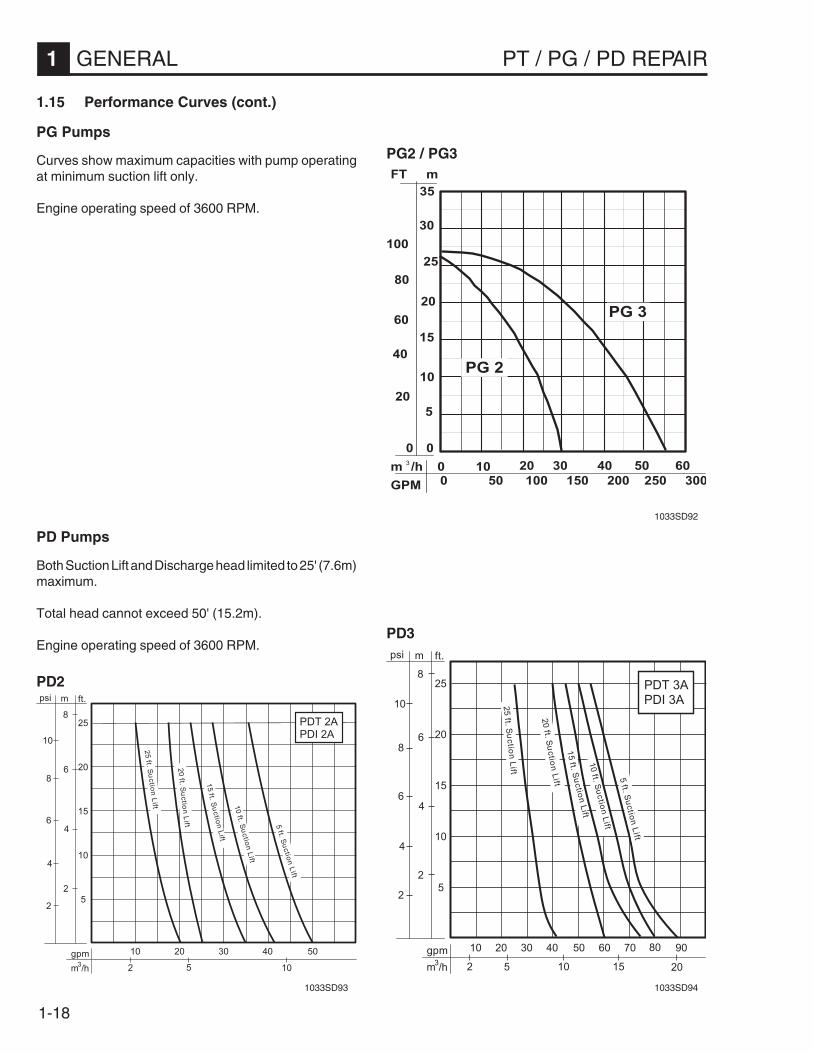
PG Pumps
Curves show maximum capacities with pump operatingat minimum suction lift only.
Engine operating speed of 3600 RPM.
PD Pumps
Both Suction Lift and Discharge head limited to 25' (7.6m)maximum.
Total head cannot exceed 50' (15.2m).
Engine operating speed of 3600 RPM.
� � � � � � � � � � � � � � � � � � � � � � � � � � � � � � � �� � � � � �� � �
� � � � � � � � � � � � � � � � � � � � � � � � � � � � � � � � � � � � � � � � � � � � �
�
�
� �
� �
� �
�
� �
� �
�
�
�
�
��� �
� � �
� � �
� � � �
� � � �
1.15 Performance Curves (cont.)
PG2 / PG3
��� #
��� ! � " � $
%&� ' �
(� )' ! �
! � "�
�
�
�
�
� �
� �
� �
� �
�
* + � � �
� � � � � � � �
� � � � � � � �� � � � � � �
+ � '
� , � � � �� , - � � ��
�� ! � " � $
%&� ' �
(� )' ! �
��� ! � " � $
%&� ' �
(� )' ! �
��� ! � " � $
%&� ' �
(� )' ! �
�� ! � " � $
%&� ' �
(� )' ! �
�
�
�
�
� �
��� #
! � "�
�
�
�
�
� �
� �
� �
� �
�
* + � � �
� � � �
� �� � � � � �
+ � '
� , � � � �� , - � � �
��� ! � " � $
%&� ' �
(� )' ! �
��� ! � " � $
%&� ' �
(� )' ! �
��� ! � " � $
%&� ' �
(� )' ! �
�� ! � " � $
%&� ' �
(� )' ! �
�
�
�
�
� �
��� ! � " � $
%&� ' �
(� )' ! �
PD2
PD3
1033SD92
1033SD93 1033SD94
2-1
PT / PG / PD REPAIR OPERATION 2
Table of Contents
2.1 Factors Affecting Pump Performance...................................................... 2-22.2 High Altitude Operation ........................................................................... 2-32.3 Before Starting ........................................................................................ 2-42.4 Starting / Stopping ................................................................................... 2-62.5 Hoses and Clamps ................................................................................ 2-112.6 Pump Wrench ....................................................................................... 2-12

2-2
2 OPERATION PT / PG / PD REPAIR
2.1 Factors Affecting PumpPerformance
Certain conditions outside the pump will influence thepump's output and ability to lift water. These factors canbe critical if the pump is operating near its maximumlimits.
Before servicing a pump, review the current applicationand conditions under which it is operating.
Suction Lift
As the height of the pump above the water increases,pump output decreases. Always locate the pump asclose to the water as possible. See Section 1.15 Perfor-mance Curves
Total Head / Discharge Head
Discharge head is the height of the discharge hose abovethe pump.
Total head is a measure of the vertical distance the pumpmust lift water.TOTAL HEAD = Suction Lift + Discharge Head + Fric-tional losses.
Pump output decreases as the discharge head or totalhead increases. See Section 1.15 Performance Curves
Altitude
Atmospheric pressure varies above or below sea level.At altitudes above sea level the maximum practicalsuction lift is reduced. See Section 2.2 High AltitudeOperation.
Frictional Loss
The friction created by the liquid as it flows through ahose, pipe, strainer or fitting creates a resistance that thepump must overcome. These losses increase with thelength of the hose, number of fittings and amount of water(GPM) flow. Frictional losses occur in both suction anddischarge lines. In long hoses, these losses will accumu-late to reduce pump output.
Suspended Soils
Suspended soils, such as sand or dirt, may add to theweight of the water, reducing the maximum practicalsuction lift. This condition would most often be observedin diaphragm type pumps operating at high lifts andpumping heavy sludges and mud mixtures.
Water Temperature
As water temperature increases above 65°F (180°C) themaximum practical suction lift will decrease. For mostnormal operating temperatures pump performance is notgreatly affected.
However, certain conditions may arise where watertemperature could be a factor. Allowing the prime waterto sit in the pump housing on a warm day could raise thewater temperature inside the pump case to the pointwhere the pump is unable to create sufficient vacuum topull the water up to it when started. Replace the water inthe pump case with fresh cold water.
While performing a SUCTION TEST the water may heatup sufficiently to give a faulty gauge reading. Completetesting within 3–4 minutes or stop engine and refill pumpcase with cold water. If possible, run continuous streamof cold water into pump case during testing.

2-3
PT / PG / PD REPAIR OPERATION 2
2.2 High Altitude Operation
When a pump is operated at elevations above sea level,the lower atmospheric pressure has a double effect onpump performance.
1. The lower atmospheric pressures cannot support ashigh a column of water, so the maximum suction liftdecreases.
2. The lower atmospheric pressure reduces the horse-power output of the gas engine, causing it to losespeed. This often results in a loss of capacity anddischarge head of the pump.
At elevations above sea level, the maximum rated suc-tion lift of the pump should be reduced.
On pumps driven by internal combustion engines, apower loss of approximately 3% for every 1000 ft. (250m)of elevation occurs and pump capacity and dischargehead should be reduced accordingly.
EDUTITLA)m(.tf
TFILNOITCUSMUMIXAM)m(.tf
leveLaeS )6.7(0.52
)006(0002 )7.6(0.22
)0021(0004 )9.5(5.91
)0081(0006 )3.5(3.71
)0042(0008 )7.4(5.51
)0003(00001 )4.4(3.41
EDUTITLA)m(.tf
EGRAHCSIDYTICAPAC
EGRAHCSIDDAEH
leveLaeS %001 %001
)006(0002 %79 %59
)0021(0004 %59 %19
)0081(0006 %39 %78
)0042(0008 %19 %38
)0003(00001 %88 %87
Maximum suction lifts at higher elevations
Loss of performance at higher elevations

2-4
2 OPERATION PT / PG / PD REPAIR
e
c d
c
b
c
f
a
1003SD38
2.3 Before Starting
PT & PG Series
1. Read safety instructions at the beginning of manual.
2. Place pump as near to water as possible, on a firm,flat, level surface.
3. To prime a PT or PG Series pump, remove primingplug (a) and fill pump case with water. If the pumpcase is not filled with water before starting, it will notbegin pumping.
4. Check for leaks between pump and engine. If water isleaking, the seal inside pump is worn or damaged.Continued operation may cause water damage toengine.
5. Check that hoses are securely attached to pump.Suction hose (b) must not have any air leaks. Tightenhose clamps (c) and coupling (d).
Check that discharge hose (e) is not restricted. Layhose out as straight as possible. Remove any twistsor sharp bends from hose which may block the flow ofwater.
6. Make sure suction strainer (f) is clean and securelyattached to end of hose. The strainer is designed toprotect the pump by preventing large objects frombeing pulled into the pump.
CAUTION: Strainer should be positioned so it willremain completely under water. Running the pumpwith the strainer above water for long periods candamage the pump.
7. Check fuel level, engine oil level, and condition of aircleaner.
WARNING
DO NOT open priming plug or loosen hose fittings ifpump is hot! Water or vapor inside pump may beunder pressure.
2-5
PT / PG / PD REPAIR OPERATION 2
2.3 Before Starting (cont.)
PD Series
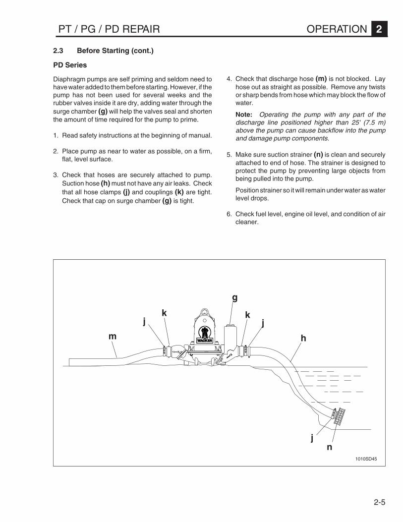
Diaphragm pumps are self priming and seldom need tohave water added to them before starting. However, if thepump has not been used for several weeks and therubber valves inside it are dry, adding water through thesurge chamber (g) will help the valves seal and shortenthe amount of time required for the pump to prime.
1. Read safety instructions at the beginning of manual.
2. Place pump as near to water as possible, on a firm,flat, level surface.
3. Check that hoses are securely attached to pump.Suction hose (h) must not have any air leaks. Checkthat all hose clamps (j) and couplings (k) are tight.Check that cap on surge chamber (g) is tight.
m
k
h
jk
j
jn
g
1010SD45
4. Check that discharge hose (m) is not blocked. Layhose out as straight as possible. Remove any twistsor sharp bends from hose which may block the flow ofwater.
Note: Operating the pump with any part of thedischarge line positioned higher than 25' (7.5 m)above the pump can cause backflow into the pumpand damage pump components.
5. Make sure suction strainer (n) is clean and securelyattached to end of hose. The strainer is designed toprotect the pump by preventing large objects frombeing pulled into the pump.
Position strainer so it will remain under water as waterlevel drops.
6. Check fuel level, engine oil level, and condition of aircleaner.
2-6
2 OPERATION PT / PG / PD REPAIR
1005SD491005SD48
e
1005SD50 1005SD51 1005SD45
CHOKE
a2
a1
b1
d1
d2b2
c1
c2
f
2.4 Starting / Stopping
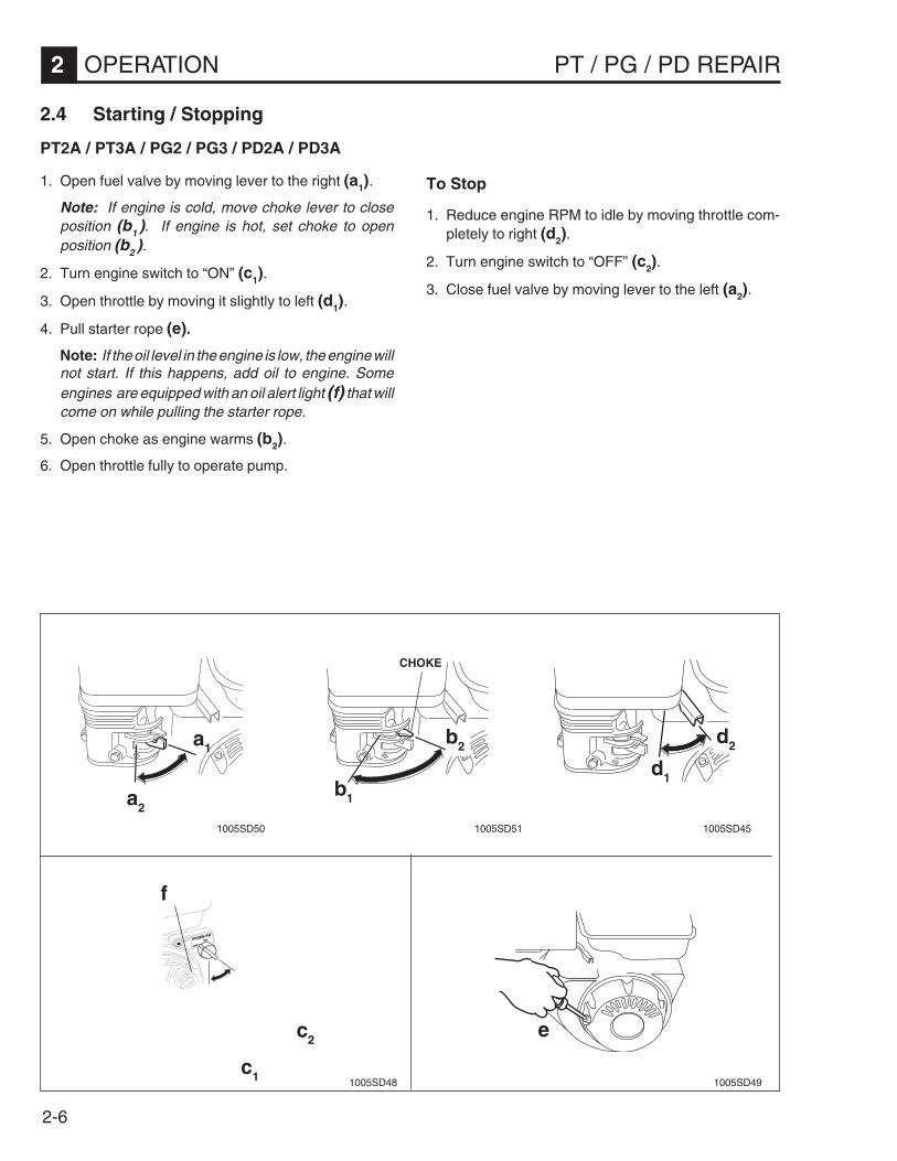
PT2A / PT3A / PG2 / PG3 / PD2A / PD3A
1. Open fuel valve by moving lever to the right (a1).
Note: If engine is cold, move choke lever to closeposition (b1 ). If engine is hot, set choke to openposition (b2 ).
2. Turn engine switch to “ON” (c1).
3. Open throttle by moving it slightly to left (d1).
4. Pull starter rope (e).
Note: If the oil level in the engine is low, the engine willnot start. If this happens, add oil to engine. Someengines are equipped with an oil alert light (f) that willcome on while pulling the starter rope.
5. Open choke as engine warms (b2).
6. Open throttle fully to operate pump.
To Stop
1. Reduce engine RPM to idle by moving throttle com-pletely to right (d2).
2. Turn engine switch to “OFF” (c2).
3. Close fuel valve by moving lever to the left (a2).

2-7
PT / PG / PD REPAIR OPERATION 2
i
��������
� �� ���
hg
g1 g2
h1 h3h2
j
1013SD77
1013SD73
2.4 Starting / Stopping (cont.)
PT2B
1. Move choke lever (g) to “CHOKE” position (g2).
2. Move throttle control (h) to “FAST” position (h3).
3. Pull starter rope (i).
Note: Some engines are equipped with an oil alertlight (j) that will flash while pulling the starter rope. Ifthis happens, the oil level is too low and the engine willnot start. Replenish oil supply before attempting tostart engine.
4. When engine starts, move throttle control to “IDLE”position (h2) and allow engine to warm up a fewminutes.
5. Move choke lever to “RUN” position (g1) when engineis warm.
6. Move throttle control to “FAST” position (h3) to oper-ate pump.
To Stop
1. Move throttle control to “OFF” position (h1).
CAUTION: Do not move choke lever to “CHOKE”position to stop engine. Backfire or engine damage mayoccur.

2-8
2 OPERATION PT / PG / PD REPAIR
1003SD39
ca2
b2b1
a1
2.4 Starting / Stopping (cont.)
PT2Y / PT3Y
1. Open fuel valve (a2).
2. Push the engine throttle lever to “run” (b2).
3. Pull out starter handle until you feel strong resistance,then let it return slowly.
4. Push down decompression lever (c).
Note: Lever will return automatically when the starteris pulled.
5. Pull starter handle to start engine. If engine does notstart, repeat steps 3 and 4.
CAUTION: NEVER operate engine without air cleaner.Engine will be damaged.
To Stop
Place the engine throttle in the “Stop” position (b1). Ifengine keeps running, stop engine by closing fuel valve(a1).
DO NOT stop engine using the decompression lever.

2-9
PT / PG / PD REPAIR OPERATION 2
e2e1
f2f1
d1
g2 g1
d2
d1
h
1007SD56
2.4 Starting / Stopping (cont.)
PT3V
1. Open fuel valve. (d1).
If engine is cold, move choke lever to the “CHOKE”position (e1 ). If engine is hot, set choke to the “RUN”position (e2 ).
2. Move throttle control to the fast ( ) position. (f1).
3. Press stop switch to the on position. (g1).
4. Pull starter rope (h).
The engine is equipped with a low oil protectionsystem. If the oil level is low, the engine will not startand the stop switch will flicker while the starter ropeis pulled. If this happens, add oil to the engine.
5. Open choke to “RUN” position as engine warms (e2).
6. Keep engine throttle in the fast position ( ) while
operating pump.
To Stop
1. Reduce engine RPM by moving throttle completely tothe idle ( ) position (f2).
2. Press engine switch to STOP (g2).
3. Close fuel valve (d2).

2-10
2 OPERATION PT / PG / PD REPAIR
c1
c2
b2
a1
a2
d1d2
d3
e
b1
1020SD71
2.4 Starting / Stopping (cont.)
PTS4V
1. Open fuel valve (a1).
2. If engine is cold, pull choke control out (b1 ). If engineis hot, push choke control in (b2 ).
3. Move throttle control to the fast position (c1).
4. Turn key switch to the start position (d3) and hold untilengine starts.
CAUTION: Do not crank engine longer than 15 secondsat a time. Extended cranking can damage starter motor.
5. To start engine using manual start: Turn key switch tothe run position (d2). Pull starter rope (e) rapidly tostart engine.
Leave key in run position (d2) while engine is running.
Note: The engine is equipped with a low oil protectionsystem. If the oil level is low, the engine will not start.Check engine oil level if engine does not start.
6. Push choke in as engine warms (b2).
7. Keep engine throttle in the fast position while operat-ing pump.
To Stop
1. Reduce engine RPM by moving throttle completely tothe idle position (c2).
2. Turn engine switch to the stop position (d1).
3. Close fuel valve (a2).
2-11
PT / PG / PD REPAIR OPERATION 2
h
f
g
1003SD40
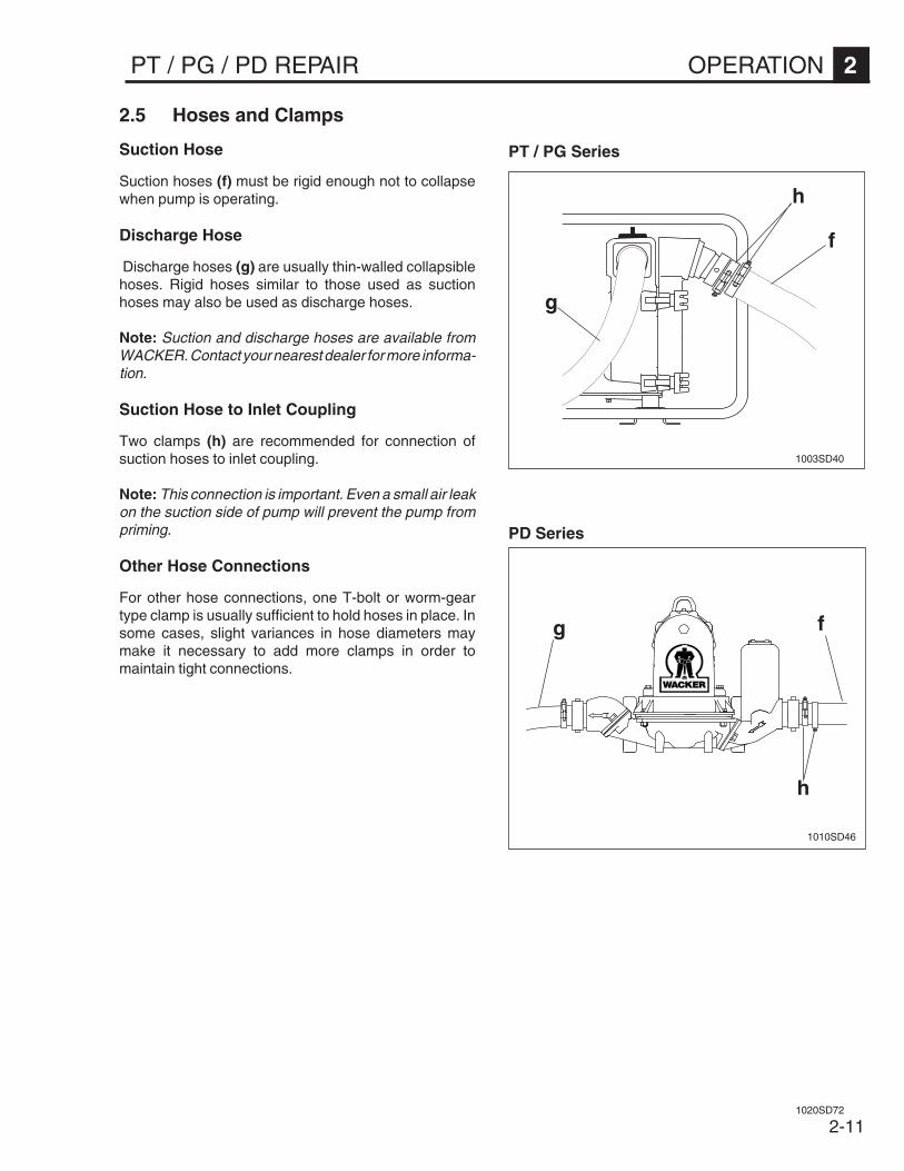
2.5 Hoses and Clamps
Suction Hose
Suction hoses (f) must be rigid enough not to collapsewhen pump is operating.
Discharge Hose
Discharge hoses (g) are usually thin-walled collapsiblehoses. Rigid hoses similar to those used as suctionhoses may also be used as discharge hoses.
Note: Suction and discharge hoses are available fromWACKER. Contact your nearest dealer for more informa-tion.
Suction Hose to Inlet Coupling
Two clamps (h) are recommended for connection ofsuction hoses to inlet coupling.
Note: This connection is important. Even a small air leakon the suction side of pump will prevent the pump frompriming.
Other Hose Connections
For other hose connections, one T-bolt or worm-geartype clamp is usually sufficient to hold hoses in place. Insome cases, slight variances in hose diameters maymake it necessary to add more clamps in order tomaintain tight connections.
1020SD72
g f
h
1010SD46
PD Series
PT / PG Series

2-12
2 OPERATION PT / PG / PD REPAIR
a
2.6 Pump Wrench
The wrench (a) supplied with the pump can be used toloosen and tighten: hose couplings, knobs on pumpcover, priming plug, and drain plug on front cover.
Store wrench on pump frame.
a
1003SD41
PT2 / PT3 Series
PTS4 Series
1020SD72

3-1
PT / PG / PD REPAIR PT SERIES PUMPS 3
Table of Contents
3.1 Description and Operation ....................................................................... 3-23.2 Periodic Maintenance Schedule .............................................................. 3-33.3 Engine Oil ............................................................................................... 3-43.4 Air Cleaner .............................................................................................. 3-63.5 Spark Plug .............................................................................................. 3-93.6 Carburetor Adjustment .......................................................................... 3-103.7 Adjusting Valve Clearance .................................................................... 3-123.8 Adjusting Engine Speed ........................................................................ 3-123.9 Cleaning Sediment Cup ........................................................................ 3-133.10 Mechanical Seal Lubrication ................................................................. 3-143.11 Adjusting Impeller Clearance ................................................................ 3-143.12 Cleaning Pump...................................................................................... 3-153.13 Storage ................................................................................................. 3-153.14 PT2 Pump Assembly ............................................................................. 3-163.15 PT3 Pump Assembly ............................................................................. 3-183.16 PTS4V Pump Assembly ........................................................................ 3-203.17 Inspecting Pump ................................................................................... 3-223.18 Flapper Valve ........................................................................................ 3-233.19 Frame Assembly ................................................................................... 3-243.20 Impeller ................................................................................................. 3-263.21 Pump Seals ........................................................................................... 3-283.22 Inspecting Pump Components .............................................................. 3-303.23 Testing .................................................................................................. 3-323.24 Troubleshooting .................................................................................... 3-33

3-2
3 PT SERIES PUMPS PT / PG / PD REPAIR
3.1 Description and Operation
PT Series Pumps use an impeller (1) and volute (2) tocreate the suction and discharge pressures required forpump operation.
The impeller is bolted directly to the engine drive shaft (3)and rotates inside the volute casing. Water is drawn intothe pump inlet (4) by the low pressure area created at theeye of the impeller. Vanes on the impeller move the liquidinto the volute where it is gathered and directed to thedischarge port (5).
A moveable tapered ring (6) set inside the volute, can beshimmed to maintain close tolerances between the vo-lute and impeller to maintain pump efficiency.
A mechanical seal (7) mounted behind the impeller,prevents water from following the engine drive shaft andseals the rear of the pump housing to prevent leakage.An oil cavity in the pump case holds the seal lubricant,reducing wear to seal surfaces.
1
1033SD43
The flapper valve (8) at the pump inlet, closes when thepump stops. This valve seals the inlet port and preventsthe prime water in the suction hose from being lost.
Pump case is easily filled with water by removing thepriming plug (9).
2
3
4
5
6
7
8
9

3-3
PT / PG / PD REPAIR PT SERIES PUMPS 3
3.2 Periodic Maintenance Schedule
The chart below lists basic pump and engine maintenance. Refer to engine manufacturer’s Operation Manual foradditional information on engine maintenance. A copy of the engine Operator’s Manual was supplied with the machinewhen it was shipped.
2TP 3TP 4TP
TPA2
TPB2
TPR2
TPY2
TPA3
TPV3
TPY3
STPV4
YLIAD )gnitratSerofeB(
.leveldiulfkcehC • • • • • • • •
.levellioenignekcehC • • • • • • • •
.enignednapmupneewtebskaelroftcepsnI • • • • • • • •
.dedeensanaelC.renaelcriatcepsnI • • • • • • • •
.erawdrahlanretxenethgitdnakcehC • • • • • • • •
NI-KAERBENIGNEWEN ).srh02tsriF(
.retlifecalperdnalioenigneegnahC • • • • • • • •
.secnaraelcevlavtsujdadnakcehC • •
SKEEW2YREVE ).srh05(
.egamadrofstnuomkcohstcepsnI • • • • • • • •
.gnisuohpmupnilioegnahC • • • • • • • •
.retlifecalperdnalioenigneegnahC • • • •
.renaelcrianaelC • • • • •
HTNOMYREVE ).srh001(
.gulpkrapsnaelcdnakcehC • • • • • •
.renaelcriaecalpeR • •
.retlifecalperdnalioenigneegnahC • • • •
.metsysgniloocnaelC •
.rebmahcnoitsubmocnaelC •
.retlifleufnaelC • •
SHTNOM3YREVE ).srh003(
.secnaraelcevlavtsujdadnakcehC • •
SHTNOM6YREVE ).srh005(
.secnaraelcevlavtsujdadnakcehC • • • •
.daehrednilycnaelC •
.renaelcriaecalpeR • •
.retlifleufenil-niecalpeR • • •
RAEYYREVE
.secnaraelcevlavtsujdadnakcehC • • •

3-4
3 PT SERIES PUMPS PT / PG / PD REPAIR
3.3 Engine Oil
PT2A / PT2R / PT3A / PT3V
Drain oil while engine is still warm.
1. Remove oil fill plug (a) and drain plug (b) to drain oil.2. Install drain plug.3. Fill engine crankcase with recommended oil up to level
of plug opening (c).
PT2A / PT2R Oil capacity: 21 oz. (0.6 liters)PT3A Oil capacity: 37 oz. (1.1 liters)PT3V Oil capacity: 41 oz. (1.2 liters)
4. Install oil filler plug.
a
b1005SD53
c
e
PT2B
Drain oil while engine is still warm.
1. Remove oil drain plug (d) and drain oil.2. Re-install drain plug.3. To add oil do one of the following:
Remove dipstick (e) and add oil through filler tube. Fillto full mark on dipstick.
orRemove filler plug (f) and fill engine crankcase throughoil filler opening with recommended oil, up to level ofplug opening (g).
Oil capacity: 20 oz. (0.6 liters).
4. When full, re-install filler plug and dipstick.
g f
1013SD74d

3-5
PT / PG / PD REPAIR PT SERIES PUMPS 3
(H)
(L)
PT2Y / PT3Y
Always check oil level before starting engine, and add oilif level is low (L). To check oil, remove dipstick (j) andinsert it into oil pan. Do not screw in the dipstick . Fillengine with oil up to the mouth of the filler port (H).
CAUTION: When checking oil level, make sure engineis level. If it is tilted, you may add too much or too little oil.If you overfill, the engine temperature will get too hot. Ifyou do not add enough oil, the engine could seize up.
j
1003SD42
PTS4V
Check engine oil level daily before starting engine. Addoil as required.
To check oil level, place pump on a level surface. Cleanarea around oil fill and remove dipstick. Pour oil (m)slowly, checking oil level occasionally with dipstick. Fill tofull mark on dipstick (n). DO NOT overfill.
When measuring oil level, screw dipstick (o) firmly inplace until cap bottoms on tube.
m
���
��
o
n
1016SD33
1016SD32
3.3 Engine Oil (cont.)

3-6
3 PT SERIES PUMPS PT / PG / PD REPAIR
3.4 Air Cleaner
PT2A / PT3A / PT2B / PT2R
Service air cleaner frequently to prevent carburetor mal-function.
NEVER run engine without air cleaner. Severe enginedamage will occur.
The engine is equipped with a dual element air cleaner.
1. Remove air cleaner cover (a). Remove both elementsand inspect them for holes or tears. Replace ele-ments if damaged. Undamaged elements may becleaned and reused.
2. To clean foam element (b):Wash in solution of mild detergent and warm water.Rinse thoroughly in clean water. Allow element to drythoroughly. Once dry, soak element in clean engineoil and squeeze out excess.
3. Paper element (c)Tap element lightly to remove excess dirt or blowcompressed air through filter from the inside out.Replace paper element if it appears heavily soiled.
a
b
c
1001SD12
WARNINGNEVER use gasoline or other types of low flashpoint solvents for cleaning the air cleaner. A fire orexplosion could result.
c
a
1013SD75
c
a
b
1006SD80
b
PT2A / PT3A
PT2B
PT2R
3-7
PT / PG / PD REPAIR PT SERIES PUMPS 3
3.4 Air Cleaner (cont.)
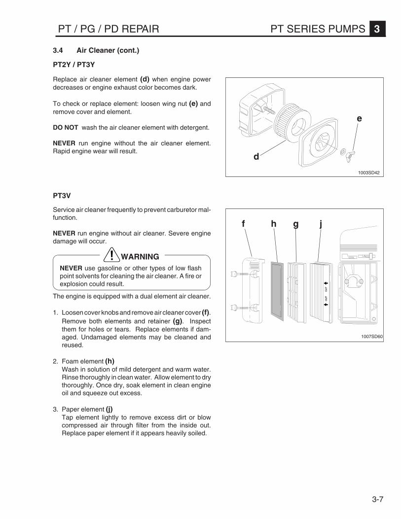
PT2Y / PT3Y
Replace air cleaner element (d) when engine powerdecreases or engine exhaust color becomes dark.
To check or replace element: loosen wing nut (e) andremove cover and element.
DO NOT wash the air cleaner element with detergent.
NEVER run engine without the air cleaner element.Rapid engine wear will result.
d
e
1003SD42
f h jg
1007SD60
PT3V
Service air cleaner frequently to prevent carburetor mal-function.
NEVER run engine without air cleaner. Severe enginedamage will occur.
The engine is equipped with a dual element air cleaner.
1. Loosen cover knobs and remove air cleaner cover (f).Remove both elements and retainer (g). Inspectthem for holes or tears. Replace elements if dam-aged. Undamaged elements may be cleaned andreused.
2. Foam element (h)Wash in solution of mild detergent and warm water.Rinse thoroughly in clean water. Allow element to drythoroughly. Once dry, soak element in clean engineoil and squeeze out excess.
3. Paper element (j)Tap element lightly to remove excess dirt or blowcompressed air through filter from the inside out.Replace paper element if it appears heavily soiled.
WARNINGNEVER use gasoline or other types of low flashpoint solvents for cleaning the air cleaner. A fire orexplosion could result.

3-8
3 PT SERIES PUMPS PT / PG / PD REPAIR
3.4 Air Cleaner (cont.)
PTS4V
Service air cleaner frequently to prevent carburetor mal-function.
NEVER run engine without air cleaner. Severe enginedamage will occur.
NEVER use gasoline or other types of low flash pointsolvents for cleaning the air cleaner. A fire or explosioncould result.
The engine is equipped with a dual element air cleaner.To service air cleaner:
1. Remove cover (a), knob (b), and retaining plate (c).
2. Remove foam precleaner (e) from filter cartridge (d).
3. Wash precleaner in liquid detergent and water.Squeeze dry in a clean cloth. Saturate precleaner inengine oil, squeeze out excess oil. Replace precleanerif it is damaged or heavily soiled.
4. To clean cartridge, remove and tap lightly on a flatsurface. Replace cartridge if it is damaged or heavilysoiled.
Note: Do not use petroleum solvents to clean precleaneror cartridge. Petroleum type solvents will damage them.Do not use pressurized air to clean cartridge. Pressur-ized air can also damage the cartridge.
1016SD34
a
b
c
e
d

3-9
PT / PG / PD REPAIR PT SERIES PUMPS 3
3.5 Spark Plug
Clean or replace spark plug as needed to ensure properoperation. Refer to the engine Owner’s Manual.
1. Remove spark plug and inspect it.2. Replace plug if the insulator is cracked or chipped.
Clean spark plug electrodes with a wire brush.3. Set gap to meet specifications (see chart).4. Tighten spark plug securely.
CAUTION: A loose spark plug can become very hotand may cause engine damage.
1006SD37
WARNINGThe muffler becomes very hot during operation andremains hot for a while after stopping the engine. Donot touch the muffler while it is hot.
A3TP/A2TP B2TP R2TP V4STP/V3TP
gulPkrapS epyt SE6RPB)KGN(CD7RWHCSOB
noipmahC8JCR
SH6B)KGN(noipmahC
C68L
noipmahCCY21CR
paGedortcelE.ni)mm(
130.0–820.0)8.0–7.0(
030.0)67.0(
820.0–420.0)7.0–6.0(
030.0)67.0(
See chart below

3-10
3 PT SERIES PUMPS PT / PG / PD REPAIR
3.6 Carburetor Adjustment
PT2A / PT3A
1. Start engine and allow it to warm up to operatingtemperature.
2. Set pilot screw (a) 2 turns out. See Note.
3. With the engine idling, turn pilot screw (a) in or out tothe setting that produces the highest RPM.
4. After pilot screw is adjusted, turn throttle stop screw(b) to obtain the standard idle speed, 1400 ±150 rpm.
Note: On some engines the pilot screw is fitted with alimiter cap (c) to prevent excessive enrichment of the air-fuel mixture in order to comply with emission regulations.The mixture is set at the factory and no adjustment shouldbe necessary. Do not attempt to remove the limiter cap.The limiter cap cannot be removed without breaking thepilot screw.
ba
c
1015SD05
PT2B
Note: All carburetor adjustments must be made with aircleaner attached to engine.
Initial Adjustment:
1. Turn needle valve (d) clockwise (in) until it just closes.Do not over-tighten or damage may occur.
2. Open needle valve by turning counterclockwise (out) 1-1/2 turns.
This initial adjustment will allow the engine to start andbe warmed up before making final adjustment.
Final Adjustment:
1. Start the engine and allow it to warm up at least twominutes.
2. Turn needle valve (d) clockwise (in) until enginemisses. This is the LEAN setting.
3. Turn the needle valve counterclockwise (out), pastthe point where the engine runs smoothly, until theengine starts missing again. This is the RICH setting.
4. Turn the needle valve clockwise (in) to the mid-pointbetween the RICH and LEAN settings.
d 1013SD76

3-11
PT / PG / PD REPAIR PT SERIES PUMPS 3
1020SD72
PT3V
1. Start engine and allow it to warm up to operatingtemperature.
2. Place throttle control in idle position. Hold carburetorthrottle lever (f) against idle speed screw. Turn idlespeed screw (g) to obtain 1300 RPM.
3. While still holding carburetor throttle lever against idlespeed screw, turn idle mixture screw (h) clockwise(lean) or counterclockwise (rich) until engine runssmoothly. Release carburetor throttle lever.
4. Adjust governed idle screw (i) to 1400 RPM. Movethrottle control to the fast position. Engine shouldaccelerate smoothly. If it does not, readjust carbure-tor, usually to a slighly richer mixture, by turning idlemixture screw (h) 1/8 turn counterclockwise.
5. Adjust top speed screw (j) to 3500 RPM.
f
g
h
ij
1016SD35
PTS4V
Note: Air cleaner must be in place and engine warmwhen making adjustments to carburetor.
1. With engine running, place throttle in SLOW positionand rotate carburetor throttle lever against the idlespeed screw (k) and hold it there.
2. Turn the idle speed screw to obtain 1300 to 1500RPM.
3. While still holding the throttle lever against the idlespeed screw, turn the idle mixture valve (l) midwaybetween limits.
4. Readjust the idle speed to 1200 RPM and releasecarburetor throttle lever. Engine should acceleratesmoothly when throttle is opened. If it does not,readjust idle mixture valve slightly counterclockwise.
k
l
3.6 Carburetor Adjustment (cont.)

3-12
3 PT SERIES PUMPS PT / PG / PD REPAIR
3.7 Adjusting Valve Clearance
PT2Y / PT3Y
Adjust valve clearance after first 20 hours of operation,and every 6 months or 500 hours thereafter.
Set valve clearance with engine cold and piston at the topof its compression stroke.
Valve Clearance Intake: 0.006" (0.15 mm)Exhaust: 0.006" (0.15 mm)
0.006 in.(0.15 mm)
1003SD47
3.8 Adjusting Engine Speed
PT2Y / PT3Y
Before making any engine adjustments, remove pumpcover and check that impeller and pump housing areclean, and that impeller clearance is correct. Adjustengine to a no-load speed of:3400 ± 100 RPM. PT2Y3800 ± 100 RPM. PT3Y
To adjust engine speed:
1. Fill pump housing with water. This will keep pumpseals cool while running engine.
2. Start engine and allow it to warm up for a minute.
3. Loosen locknut (b) on throttle stop screw (c). Turnscrew in to decrease speed, out to increase speed.Make sure throttle lever (a) is touching stop screwbefore measuring RPM. Tighten locknut after correctengine speed is set.
CAUTION: Running pump at a speed higher than thatlisted in “Technical Data” can damage pump and engine.DO NOT adjust governor setting.
a
b
c
1003SD48
3-13
PT / PG / PD REPAIR PT SERIES PUMPS 3
d
e
1001SD13
1006SD76
d
e
f
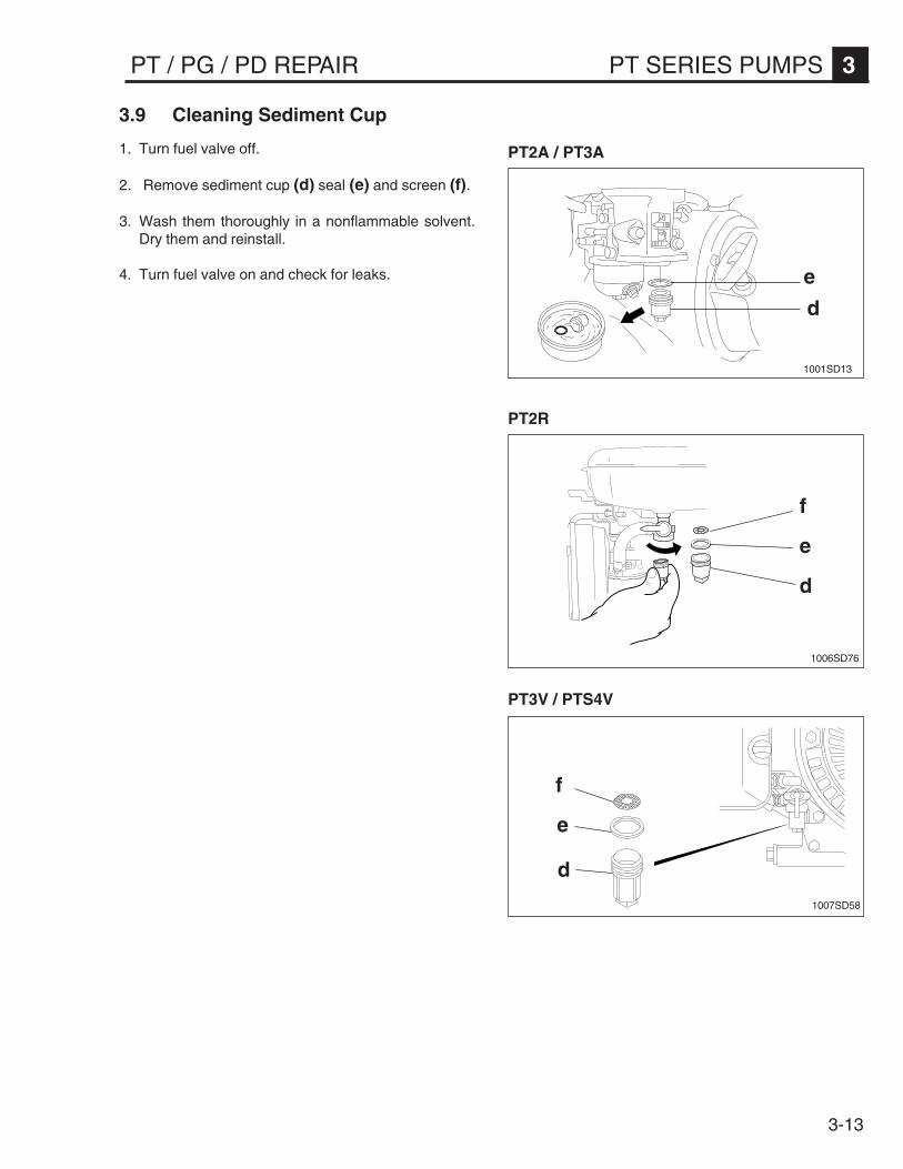
3.9 Cleaning Sediment Cup
1. Turn fuel valve off.
2. Remove sediment cup (d) seal (e) and screen (f).
3. Wash them thoroughly in a nonflammable solvent.Dry them and reinstall.
4. Turn fuel valve on and check for leaks.
d
e
f
1007SD58
PT3V / PTS4V
PT2R
PT2A / PT3A
3-14
3 PT SERIES PUMPS PT / PG / PD REPAIR
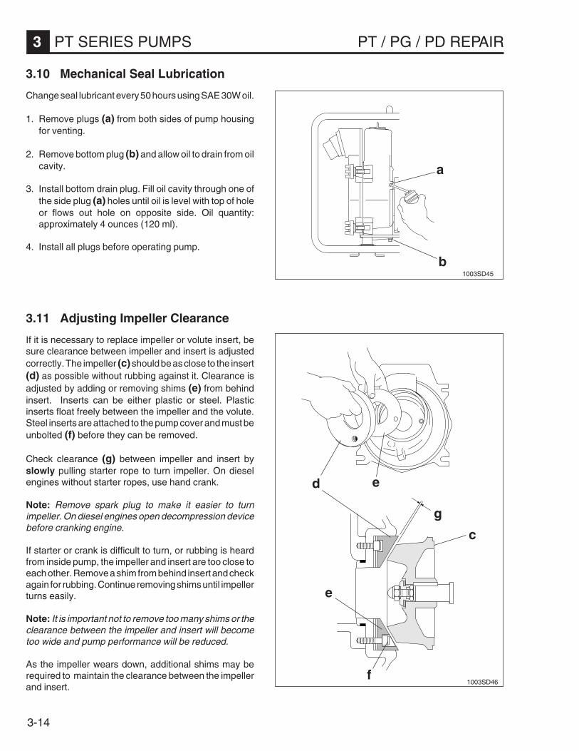
3.10 Mechanical Seal Lubrication
Change seal lubricant every 50 hours using SAE 30W oil.
1. Remove plugs (a) from both sides of pump housingfor venting.
2. Remove bottom plug (b) and allow oil to drain from oilcavity.
3. Install bottom drain plug. Fill oil cavity through one ofthe side plug (a) holes until oil is level with top of holeor flows out hole on opposite side. Oil quantity:approximately 4 ounces (120 ml).
4. Install all plugs before operating pump.
3.11 Adjusting Impeller Clearance
If it is necessary to replace impeller or volute insert, besure clearance between impeller and insert is adjustedcorrectly. The impeller (c) should be as close to the insert(d) as possible without rubbing against it. Clearance isadjusted by adding or removing shims (e) from behindinsert. Inserts can be either plastic or steel. Plasticinserts float freely between the impeller and the volute.Steel inserts are attached to the pump cover and must beunbolted (f) before they can be removed.
Check clearance (g) between impeller and insert byslowly pulling starter rope to turn impeller. On dieselengines without starter ropes, use hand crank.
Note: Remove spark plug to make it easier to turnimpeller. On diesel engines open decompression devicebefore cranking engine.
If starter or crank is difficult to turn, or rubbing is heardfrom inside pump, the impeller and insert are too close toeach other. Remove a shim from behind insert and checkagain for rubbing. Continue removing shims until impellerturns easily.
Note: It is important not to remove too many shims or theclearance between the impeller and insert will becometoo wide and pump performance will be reduced.
As the impeller wears down, additional shims may berequired to maintain the clearance between the impellerand insert.
b
a
1003SD45
e
c
d
e
f1003SD46
g
3-15
PT / PG / PD REPAIR PT SERIES PUMPS 3
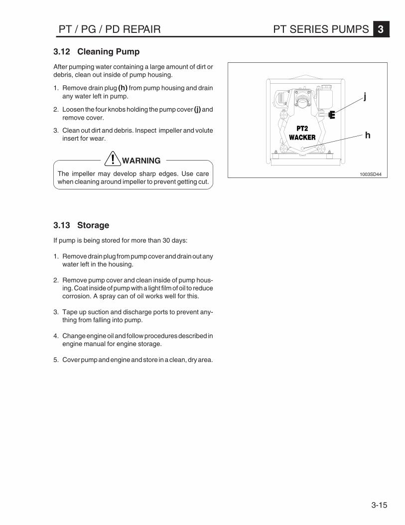
3.12 Cleaning Pump
After pumping water containing a large amount of dirt ordebris, clean out inside of pump housing.
1. Remove drain plug (h) from pump housing and drainany water left in pump.
2. Loosen the four knobs holding the pump cover (j) andremove cover.
3. Clean out dirt and debris. Inspect impeller and voluteinsert for wear.
WARNING
The impeller may develop sharp edges. Use carewhen cleaning around impeller to prevent getting cut.
j
h
1003SD44
3.13 Storage
If pump is being stored for more than 30 days:
1. Remove drain plug from pump cover and drain out anywater left in the housing.
2. Remove pump cover and clean inside of pump hous-ing. Coat inside of pump with a light film of oil to reducecorrosion. A spray can of oil works well for this.
3. Tape up suction and discharge ports to prevent any-thing from falling into pump.
4. Change engine oil and follow procedures described inengine manual for engine storage.
5. Cover pump and engine and store in a clean, dry area.
3-16
3 PT SERIES PUMPS PT / PG / PD REPAIR
2224
21
6
26[L2] 25
1003SD661003SD67
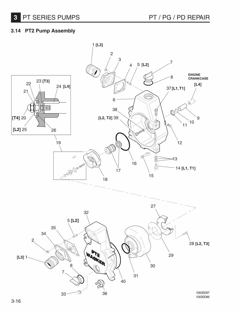
3.14 PT2 Pump Assembly
23 [T3]
[T4] 20
19
14 [L1, T1]
18
16
29
28 [L2, T3]
30
40
27
33
8
7
[L3] 1
2
3435
5 [L2]
38
36
31
11
[L2, T2] 39
8
75 [L2]
1 [L3]
23
4
1715
13
12
109
32
37 [L1, T1] [L4] [L4]
ENGINECRANKCASE

3-17
PT / PG / PD REPAIR PT SERIES PUMPS 3
[L1] - 0029311 [L2] - 0029312 [L3] - 0079356 [L4] - 0073287[T1] - 28 ft.lbs. (38 Nm) [T2] - 16 ft.lbs. (22 Nm) [T3] - 11 ft.lbs. (15 Nm) [T4] - 25 ft.lbs. (34 Nm)
1 Fitting - nipple ..............................................................................................22 Locknut M8 .................................................................................................83 Flange - port ................................................................................................14 Gasket - priming plug ..................................................................................15 Stud M8x30 .................................................................................................86 Kit - pump housing (incl. 7 & 8) ...................................................................17 Plug - priming ..............................................................................................28 Gasket - priming plug ..................................................................................29 Sleeve - engine shaft ..................................................................................110 Washer - flat ................................................................................................111 Seal-shaft ....................................................................................................1
Plug M10 hex ..............................................................................................3Ring - sealing ..............................................................................................3
13 Washer 13 ...................................................................................................314 Screw M12x50 ............................................................................................215 Bolt - eye .....................................................................................................416 O-Ring ........................................................................................................117 Seal - mechanical (std.) ..............................................................................118 Kit - impeller ................................................................................................119 Kit - mounting ..............................................................................................120 Nut M8 hex. .................................................................................................121 Ring - sealing ..............................................................................................122 Hub - impeller mount ...................................................................................123 Nut 5/16-24 hex jam ....................................................................................124 Key - square ................................................................................................125 Stud - impeller mount ..................................................................................126 Gasket - impeller mounting .........................................................................127 Kit - seal insert (incl. 28) ..............................................................................128 Screw M8x25 ..............................................................................................2
Shim .005"" .............................................................................................A/RShim .010"" .............................................................................................A/RShim .020"" .............................................................................................A/RShim .040"" .............................................................................................A/R
30 Volute ..........................................................................................................131 O-Ring ........................................................................................................132 Kit - pump cover (incl. 7 & 8) ......................................................................1
Plug M20, hex. ............................................................................................1Ring - sealing ..............................................................................................1
34 Flange - port ................................................................................................135 Gasket - flapper ..........................................................................................136 Knob ...........................................................................................................437 Screw M12x40 ............................................................................................238 Ring - sealing ..............................................................................................439 Screw M8x45 ..............................................................................................240 O-Ring ........................................................................................................1
REF. DESCRIPTION QTY.
12
29
33

3-18
3 PT SERIES PUMPS PT / PG / PD REPAIR
1004SD131003SD67
3.15 PT3 Pump Assembly
2118
20 [T3]
[L2, T1] 22 23
1
12
37
16
19
25 [L2, T2]
27
29
35
[L3] 2
3233
34
3026
24
15
14
13
10
11 [L1, T5]
8
5
5
36 [L1, T5]
3
4
43
[L4]
[L2, T1] 38
ENGINECRANKCASE
[L4]
7
6
2 [L3]
9
31
28
[T4] 17
3-19
PT / PG / PD REPAIR PT SERIES PUMPS 3
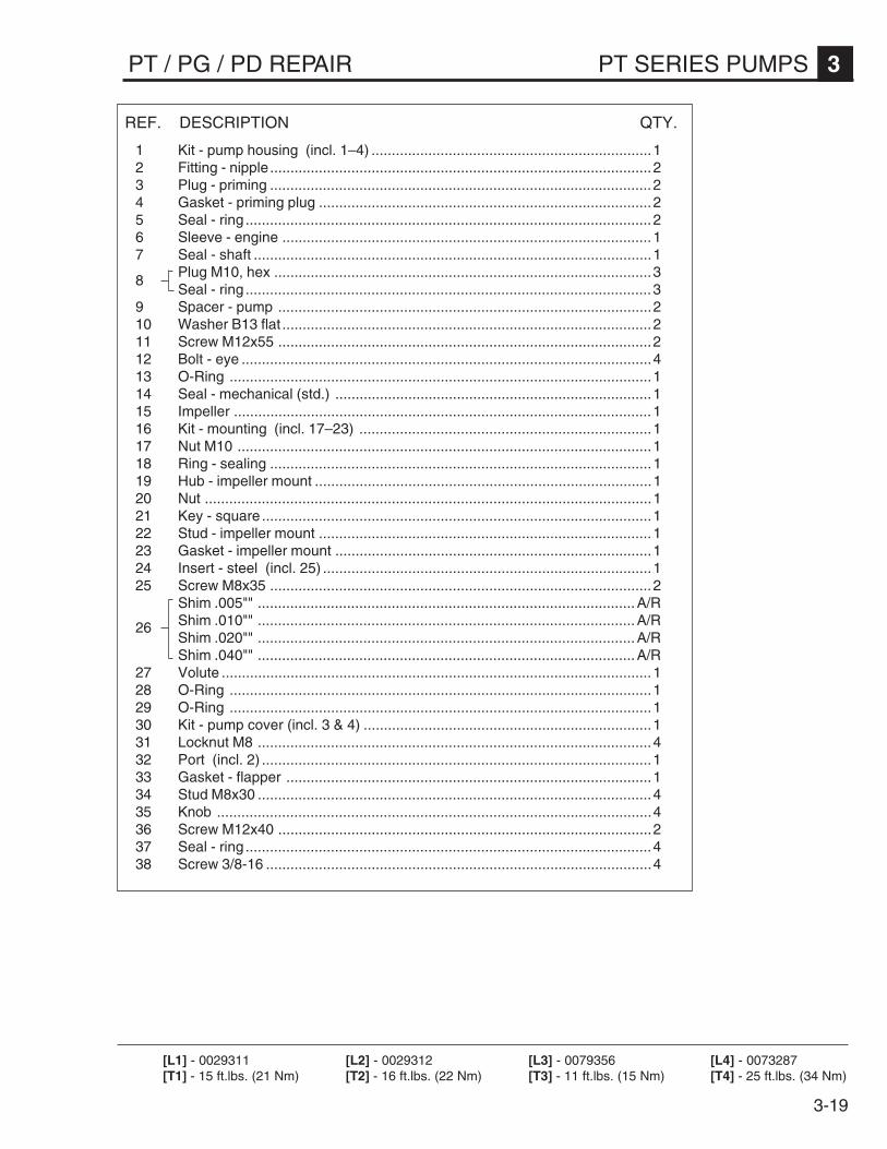
[L1] - 0029311 [L2] - 0029312 [L3] - 0079356 [L4] - 0073287[T1] - 15 ft.lbs. (21 Nm) [T2] - 16 ft.lbs. (22 Nm) [T3] - 11 ft.lbs. (15 Nm) [T4] - 25 ft.lbs. (34 Nm)
1 Kit - pump housing (incl. 1–4) .....................................................................12 Fitting - nipple..............................................................................................23 Plug - priming ..............................................................................................24 Gasket - priming plug ..................................................................................25 Seal - ring ....................................................................................................26 Sleeve - engine ...........................................................................................17 Seal - shaft ..................................................................................................1
Plug M10, hex .............................................................................................3Seal - ring ....................................................................................................3
9 Spacer - pump ............................................................................................210 Washer B13 flat ...........................................................................................211 Screw M12x55 ............................................................................................212 Bolt - eye .....................................................................................................413 O-Ring ........................................................................................................114 Seal - mechanical (std.) ..............................................................................115 Impeller .......................................................................................................116 Kit - mounting (incl. 17–23) ........................................................................117 Nut M10 ......................................................................................................118 Ring - sealing ..............................................................................................119 Hub - impeller mount ...................................................................................120 Nut ..............................................................................................................121 Key - square ................................................................................................122 Stud - impeller mount ..................................................................................123 Gasket - impeller mount ..............................................................................124 Insert - steel (incl. 25) .................................................................................125 Screw M8x35 ..............................................................................................2
Shim .005"" .............................................................................................A/RShim .010"" .............................................................................................A/RShim .020"" .............................................................................................A/RShim .040"" .............................................................................................A/R
27 Volute ..........................................................................................................128 O-Ring ........................................................................................................129 O-Ring ........................................................................................................130 Kit - pump cover (incl. 3 & 4) .......................................................................131 Locknut M8 .................................................................................................432 Port (incl. 2) ................................................................................................133 Gasket - flapper ..........................................................................................134 Stud M8x30 .................................................................................................435 Knob ...........................................................................................................436 Screw M12x40 ............................................................................................237 Seal - ring ....................................................................................................438 Screw 3/8-16 ...............................................................................................4
8
26
REF. DESCRIPTION QTY.

3-20
3 PT SERIES PUMPS PT / PG / PD REPAIR
3.16 PTS4V Pump Assembly
21
2 [L1]
23 [L3]22
20
24
4
3
30
29
31
26
25
27
28 [T2, L3]
9
6
ENGINECRANKSHAFT
2 [L1]
4
3
1
7
1020SD61
[T3, L3] 13
8 [T1, L2]
19
1817
[T2, L2] 16 1514
[G1] 5
11 [T2, L2]12 [L2]
10 [L2]
32

3-21
PT / PG / PD REPAIR PT SERIES PUMPS 3
1 Kit - pump housing (incl. 2–4) .....................................................................12 Fitting - nipple..............................................................................................23 Plug - priming ..............................................................................................24 Gasket - priming plug ..................................................................................25 Seal - shaft ..................................................................................................16 Plug M10, hex .............................................................................................37 Seal - ring ....................................................................................................38 Screw M12x40 ............................................................................................49 Bolt - eye .....................................................................................................410 Stud M8x20 .................................................................................................211 Nut M8 ........................................................................................................212 Setscrew M8x10 .........................................................................................313 Screw 7/16-14x1-1/4 ...................................................................................414 Gasket - pump oil cover ..............................................................................115 Cover - oil chamber .....................................................................................116 Screw M8x20 ..............................................................................................517 O-Ring ........................................................................................................118 Seal - mechanical (std.) ..............................................................................119 Impeller .......................................................................................................120 Kit - suction port replacement (incl. 2) ........................................................121 Locknut M8 .................................................................................................422 Gasket - flapper ..........................................................................................123 Stud M8x30 .................................................................................................424 Kit - pump cover (incl. 3 & 4) .......................................................................125 Volute ..........................................................................................................1
Shim .005"" .............................................................................................A/RShim .010"" .............................................................................................A/RShim .020"" .............................................................................................A/RShim .040"" .............................................................................................A/R
27 Kit - volute insert (incl. 28) ..........................................................................128 Screw M8x35 ..............................................................................................329 O-ring ..........................................................................................................130 O-ring ..........................................................................................................131 Knob ...........................................................................................................432 Sleeve - shaft ..............................................................................................1
[G1] - Gease #2[L1] - 0079356 [L2] - 0029311 [L3] - 0029312[T1] - 28 ft.lbs. (38 Nm) [T2] - 16 ft.lbs. (22 Nm) [T3] - 40 ft.lbs. (54 Nm)
26
REF. DESCRIPTION QTY.
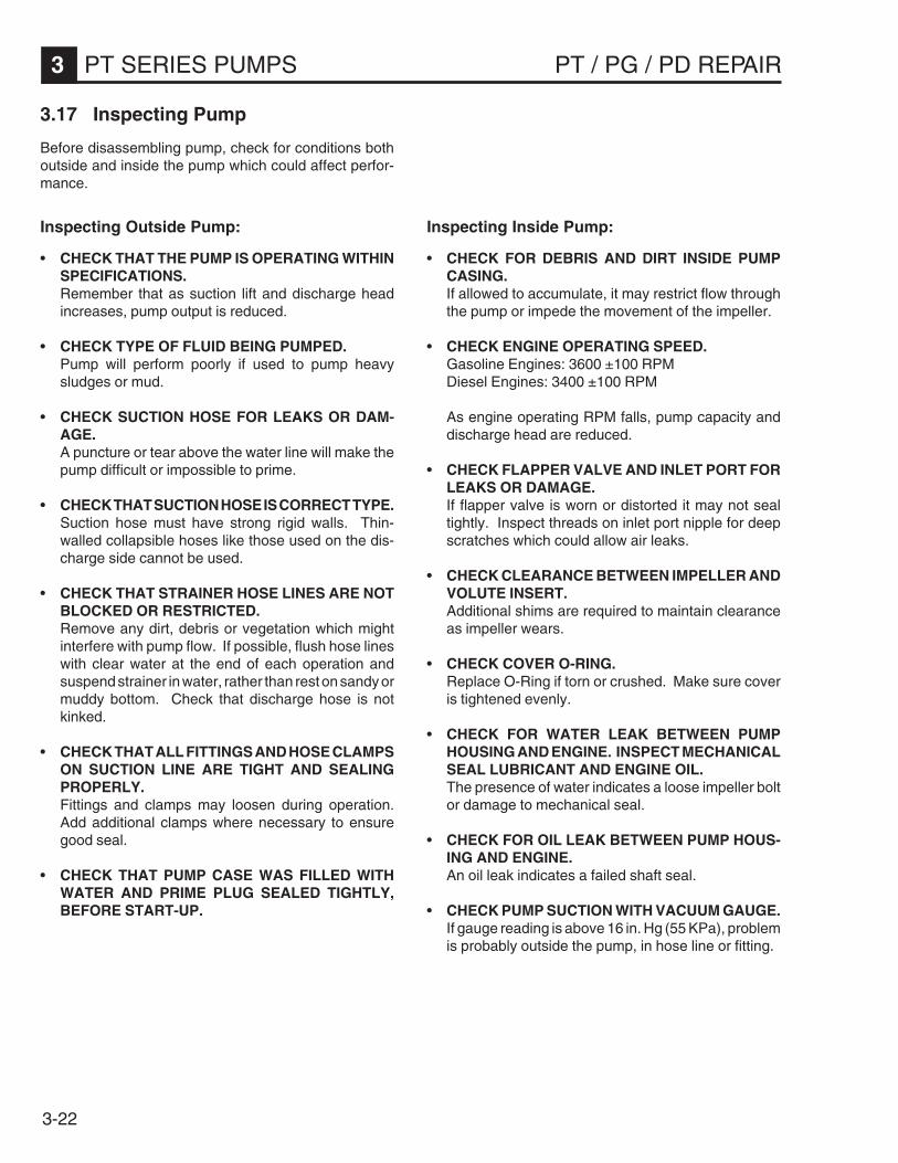
3-22
3 PT SERIES PUMPS PT / PG / PD REPAIR
3.17 Inspecting Pump
Before disassembling pump, check for conditions bothoutside and inside the pump which could affect perfor-mance.
Inspecting Outside Pump:
• CHECK THAT THE PUMP IS OPERATING WITHINSPECIFICATIONS.Remember that as suction lift and discharge headincreases, pump output is reduced.
• CHECK TYPE OF FLUID BEING PUMPED.Pump will perform poorly if used to pump heavysludges or mud.
• CHECK SUCTION HOSE FOR LEAKS OR DAM-AGE.A puncture or tear above the water line will make thepump difficult or impossible to prime.
• CHECK THAT SUCTION HOSE IS CORRECT TYPE.Suction hose must have strong rigid walls. Thin-walled collapsible hoses like those used on the dis-charge side cannot be used.
• CHECK THAT STRAINER HOSE LINES ARE NOTBLOCKED OR RESTRICTED.Remove any dirt, debris or vegetation which mightinterfere with pump flow. If possible, flush hose lineswith clear water at the end of each operation andsuspend strainer in water, rather than rest on sandy ormuddy bottom. Check that discharge hose is notkinked.
• CHECK THAT ALL FITTINGS AND HOSE CLAMPSON SUCTION LINE ARE TIGHT AND SEALINGPROPERLY.Fittings and clamps may loosen during operation.Add additional clamps where necessary to ensuregood seal.
• CHECK THAT PUMP CASE WAS FILLED WITHWATER AND PRIME PLUG SEALED TIGHTLY,BEFORE START-UP.
Inspecting Inside Pump:
• CHECK FOR DEBRIS AND DIRT INSIDE PUMPCASING.If allowed to accumulate, it may restrict flow throughthe pump or impede the movement of the impeller.
• CHECK ENGINE OPERATING SPEED.Gasoline Engines: 3600 ±100 RPMDiesel Engines: 3400 ±100 RPM
As engine operating RPM falls, pump capacity anddischarge head are reduced.
• CHECK FLAPPER VALVE AND INLET PORT FORLEAKS OR DAMAGE.If flapper valve is worn or distorted it may not sealtightly. Inspect threads on inlet port nipple for deepscratches which could allow air leaks.
• CHECK CLEARANCE BETWEEN IMPELLER ANDVOLUTE INSERT.Additional shims are required to maintain clearanceas impeller wears.
• CHECK COVER O-RING.Replace O-Ring if torn or crushed. Make sure coveris tightened evenly.
• CHECK FOR WATER LEAK BETWEEN PUMPHOUSING AND ENGINE. INSPECT MECHANICALSEAL LUBRICANT AND ENGINE OIL.The presence of water indicates a loose impeller boltor damage to mechanical seal.
• CHECK FOR OIL LEAK BETWEEN PUMP HOUS-ING AND ENGINE.An oil leak indicates a failed shaft seal.
• CHECK PUMP SUCTION WITH VACUUM GAUGE.If gauge reading is above 16 in. Hg (55 KPa), problemis probably outside the pump, in hose line or fitting.

3-23
PT / PG / PD REPAIR PT SERIES PUMPS 3
3.18 Flapper Valve
The flapper valve (1) is located at the pump inlet (2). During operation, this valve is open allowing a free path for waterto flow into the pump case. When the pump is stopped, it closes and prevents water in the suction line from being lost.
A leak around the flapper gasket will cause the suction line to lose its prime and make the pump difficult or impossibleto operate.
Recommended tools:Socket wrench - 13mm
1033SD49
1
2
3 4
Removal:
1. Remove four locknuts (3) mounting suction (inlet)port (2) to pump.
2. Remove inlet port and flapper valve assembly (1).
Installation:
3. Install new flapper valve assembly, with large washer(4) facing inside of cover and flap opening facingdown. This washer acts as a counterweight and helpsseal the flapper gasket against the pump inlet whenpump stops.
4. Mount inlet port (2) to pump. Tighten locknuts (3)evenly until flapper gasket begins to compress.
CAUTION: DO NOT overtighten. Overtightening maydistort flapper gasket causing an air leak at inlet port.

3-24
3 PT SERIES PUMPS PT / PG / PD REPAIR
3.19 Frame Assembly
1004SD40
2 1
3
4
5
9
6
5
10
7
8
(PT2 Shown)

3-25
PT / PG / PD REPAIR PT SERIES PUMPS 3
Removal:
1. Remove hardware (1) mounting console (2) toshockmounts (3). Remove from frame.
Note: Mounting hardware varies on all PT Series Pumps.
2. Remove four screws (4), washers (5), and four lock-nuts (6) mounting engine side (7) to console.
3. Remove two screws (8) and washers (9) mountingpump side (10) to console.
3.19 Frame Assembly (cont.)
Installation:
1. Mount pump side (10) to console (2) using screws (8)and washers (9). Apply Loctite 243 or an equivalentmedium strength threadlocker and torque to 28 ft.lbs(38 Nm).
2. Mount engine side (7) to console (2) using screws(4), washers (5), and locknuts (6). Torque to 29 ft.lbs(40 Nm).
3. Mount console (2) to shockmounts (3) using hard-ware (1).
WARNING
Before you start the machine, ensure that all toolshave been removed from the machine and thatreplacement parts and adjusters are firmly tight-ened.
Note: See sealant and torque reference charts in backof book for appropriate threadlocking adhesives andtorque values.
Recommended tools:Socket wrench - 1/2" (13mm), 11/16" (17mm), 3/4" (19mm)Allen wrench - 6mm

3-26
3 PT SERIES PUMPS PT / PG / PD REPAIR
1003SD671033SD50
2
18
1011
5
3
4
76
1014
7
11 13
12
6
9
3.20 Impeller
The impeller (1) will wear gradually during normal pump operations. The amount of wear depends on the quantity andcomposition of the solid particles being carried in the water.
The impeller should be replaced, if a new insert or additional shims are no longer sufficient to maintain clearancebetween insert and impeller.Note: Shim thickness should not exceed 0.125" (3mm).

3-27
PT / PG / PD REPAIR PT SERIES PUMPS 3
3.20 Impeller (cont.)
Recommended tools:Socket wrench - 1/2" (13mm), 9/16"Pry bar
Removal:
1. Remove pump / engine from frame. See Section 3.19Frame Assembly.
2. Loosen four knobs (2) mounting front volute housing(3) to rear impeller housing (4). Thoroughly wash outand clean around impeller (1) and inside of housing.
3. Remove bottom plug (5) from pump housing anddrain oil from pump.
Note: In the interests of invironmental protection, placeplastic sheeting and a container under the pump to collectthe liquid which drains off. Dispose of this liquid properly.
4. Remove dome nut (6) and sealing ring (7). Using apry bar or 3-jaw puller, insert behind impeller and pullimpeller off of engine shaft being carefull not to dam-age O-ring (8) behind impeller.
CAUTION: Use care when handling impeller to avoiddamage to seal surfaces.
Note: The mechanical seal (9) will remain on the impellerwhen it is removed.
5. Push hub (10) out from impeller and remove gasket(11).
6. Loosen jam nut (12) securing stud (13) in engineshaft.
7. Remove stud and key (14).
Installation:
1. Install mechanical seal (9) on impeller (1) if notalready done. See Section 3.21 Pump Seals.
2. Press hub (10), with gasket (11), into front end ofimpeller.
3. Install long threaded end of stud (13) in engine shaftmaking sure enough of the stud is exposed to mountthe impeller. Apply Loctite 271 or an equivalent highstrength threadlocker and secure with jam nut (12).
Note: See chart for stud locating dimensions and torquevalues for jam nuts & dome nuts.
4. Place key (14) in slot on engine shaft.
5. Install impeller (1) on engine shaft. Place sealing ring(7) over stud and secure with dome nut (6). ApplyLoctite 222 or an equivalent low strength threadlocker.
6. Turn impeller by hand and check that it turns freely.
Note: If back of impeller rubs on pump housing, removeimpeller and install one additional copper washer be-tween impeller and shaft sleeve.
7. Install drain plug (5). Fill pump oil cavity to specifiedlevel and check for leaks between pump housing andengine.
Note: See Sections 1.10, 1.11, & 1.12 Technical Data foroil level specifications.
8. Mount front volute housing (3) to rear impeller hous-ing (4) using four knobs (2).
9. Install spark plug and pull starter rope. If impeller isbinding, remove shims from behind volute insert. SeeSection 3.11 Adjusting Impeller Clearance.
WARNING
Remove spark plug from engine before testingimpeller.
.MIDGNITACOL)31(dutS)mm(.ni
EULAVEUQROT)21(tuNmaJ
)mN(.sbl.tf
EULAVEUQROT)6(tuNemoD
)mN(.sbl.tf
A2TPB2TPR2TPY2TP
)52(00.1 )51(11 )43(52
A3TPV3TPY3TP
)03(61/3-1 )24(13 )73(72
V4STP )82(8/1-1 )72(02 )73(72
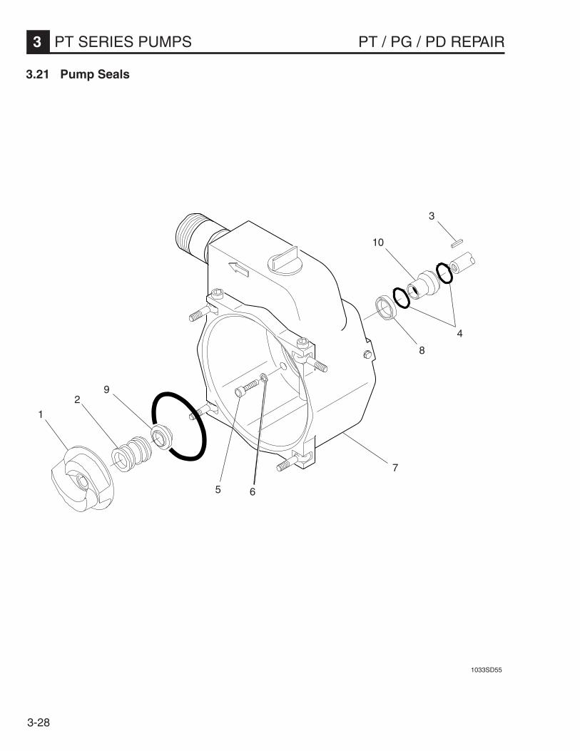
3-28
3 PT SERIES PUMPS PT / PG / PD REPAIR
1033SD55
1
3.21 Pump Seals
29
8
10
4
3
5 6
7

3-29
PT / PG / PD REPAIR PT SERIES PUMPS 3
3.21 Pump Seals (cont.)
Removal:
1. Remove impeller (1). See Section 3.20 Impeller.
2. Pull mechanical seal (2) off impeller.
3. Remove key (3) and washer(s) (4) from engine shaft.
Note: The quantity of washers may vary between pumps.When removing washers, note their position and quantityon engine shaft to ensure that they will be reinstalledcorrectly.
4. Remove four screws (5) and washers (6) mountingthe pump housing (7) to the engine. Remove pumphousing.
5. Remove shaft seal (8) from rear of pump housing.
6. Press stationary half of mechanical seal (9) out frompump housing.
7. Remove sleeve (10) and any remaining washersfrom engine shaft for inspection or replacement.
Installation:
CAUTION: When handling and installing the mechani-cal seal, it is important to keep hands and tools clean andto avoid touching or pressing on seal faces.
1. Grease shaft seal (8) using Shell Alvania #2 orequivalent. Press seal with open end facing into pumphousing (7).
2. Slide sleeve (10) over engine shaft. Be sure toreplace any washers that were removed.
Note: If the quantity or position of the washers are indoubt, install sleeve with one washer on either side.
3. Press stationary half of mechanical seal (9) into pumphousing.
4. Slide pump housing over engine shaft being carefulnot to cut lip of shaft seal (8) on keyway in shaft.
5. Mount pump housing (7) to engine using four screws(5) and washers (6). Apply Loctite 271 or an equiva-lent high strength threadlocker and torque to 16 ft.lbs(22 Nm).
6. Push mechanical seal (2) completely on impeller (1).
7. Install impeller (1). See Section 3.20 Impeller.
Recommended tools:Socket wrench - 1/2" (13mm)Allen wrench - 1/4", 5/16", 3/8"

3-30
3 PT SERIES PUMPS PT / PG / PD REPAIR
3.22 Inspecting Pump Components
1033SD55
1033SD55
5
2
1
Contact Surface
3
6
4
4
7
Oil Cavity

3-31
PT / PG / PD REPAIR PT SERIES PUMPS 3
Mechanical Seal
The PT Series Pumps use a carbon-ceramic mechanicalseal (1). Its design provides excellent wear and sealingcharacteristics. Inspect the seal for damage and wear asdescribed below.
1. The two contact surfaces between seal halves shouldhave flat, smooth surface and be absolutely free ofany scratches, cracks, nicks, or pitting.
CAUTION: Replace seal if surfaces appear damagedin any way.
2. Inspect the rubber ring, inside the rotating seal half(2), for damage.
Note: The rotating seal half must seal tightly around theimpeller (3). For this reason it is important to examine theimpeller surface, in the area where the seal mounts, forpitting, rust or other damage which could prevent a goodfit.
3. Inspect the O-ring on the stationary half (4). Makesure it seals tight enough to prevent water fromleaking past it and the seal from spinning in housing.
3.22 Inspecting Pump Components (cont.)
Shaft Seal and Sleeve
The shaft seal (5) is used to prevent the seal lubricantfrom leaking out of the oil cavity in the pump housing. Itis located at the back of the pump housing and rides ona metal sleeve (6) which is placed over the engine shaft.
If oil is observed leaking from the rear of the pumphousing, both the seal and sleeve must be inspected.The surface of the sleeve, where the seal rides, should besmooth.
CAUTION: Replace sleeve if rusted, pitted or looksworn. Always replace it along with the shaft seal.
Sleeve Washers
Inspect the condition of the copper sleeve washers (7).These washers vary between pumps and in some casesare used to shim the impeller (3) to prevent it fromrubbing against the oil cover or pump housing.
CAUTION: Replace washers if they are badly crushedor distorted.
Washers may be located both in front of and behind theshaft seal (5).
Note: Install washers in the same position and quantitiesas they were removed.
If impeller (3) rubs against housing after it has beeninstalled, insert one additional copper washer betweenimpeller and sleeve (6).
Note: On PT2 Series Pumps an aluminum sleevewasher is used. Install this washer directly behindimpeller.

3-32
3 PT SERIES PUMPS PT / PG / PD REPAIR
3.23 Testing
Suction Test
Required Tools:Vacuum Gauge - P/N 28755Tachometer
1. Fill pump housing with cold water until it flows out fromdischarge port.
2. Tighten pump cover and prime plug .
3. Bring engine up to operating speed. Check engineRPM. See Section 1.10, 1.11, & 1.12 Technical Datafor different PT engine speeds.
Note: Keep pump housing filled with water at all timeswhile pump is running. If too much water is lost during testprocedure, stop engine and reprime pump. It may benecessary to tilt pump or partially cover discharge port, toprevent water in the pump housing from being lost whilestill allowing air to be vented.
4. Grease mounting face of vacuum gauge (1), to en-sure a good seal. Press gauge over inlet port.
5. Gauge reading should slowly climb and then holdsteady.
6. With gauge still against inlet port, turn off engine.Gauge reading should not change.
Note: See vacuum chart for appropriate gauge read-ings.
This test MUST be completed within a few minutes toprevent the water in the pump housing from getting hot,which will result in lower readings. If possible, allow coldwater to run into discharge port while testing pump.
1033SD631033SD65
1
tnellecxE yrotcafsitaS
gH.ni)aPK(
42–02)28–86(
02–61)86–55(

3-33
PT / PG / PD REPAIR PT SERIES PUMPS 3
3.24 Troubleshooting
Problem / Symptom
Pump does not take in water.
Pump takes in water; little or no discharge.
Suction hose leaks at inlet.
Discharge hose does not stay on coupling.
Impeller does not turn; pump is hard to start.
Engine does not start or stops during operation.
Reason / Remedy
1. Not enough priming water in housing.2. Engine speed too low. Adjust speed.3. Strainer plugged. Clean strainer.4. Suction hose damaged. Replace or repair hose.5. Air leak at suction port. Check that fittings are tight and
sealing properly.6. Pump too high above water.7. Debris collecting in pump housing. Clean pump hous-
ing.8. Too much clearance between impeller and insert.
1. Engine speed too low. Adjust speed.2. Suction strainer partially plugged. Clean strainer.3. Impeller worn. Adjust clearance by adding shims or
replace impeller.4. Volute insert worn or damaged. Adjust clearance or
replace insert.
1. Clamps are not sealing properly. Tighten, replace, oradd clamp.
2. Hose diameter is too large.3. Hose is damaged.
1. Pressure may be too high for clamps being used. Addanother clamp.
2. Hose kinked or end blocked. Check hose.
1. Impeller jammed or blocked.Open pump cover andclean dirt and debris from inside of pump housing.
2. Impeller and insert binding. Adjust clearance by re-moving shim from behind insert.
1. Debris in pump housing, blocking impeller.2. Low oil level in engine.

3-34
3 PT SERIES PUMPS PT / PG / PD REPAIR
Notes:

4-1
PT / PG / PD REPAIR PG SERIES PUMPS 4
Table of Contents
4.1 Description and Operation ....................................................................... 4-24.2 Periodic Maintenance Schedule .............................................................. 4-34.3 Air Cleaner .............................................................................................. 4-44.4 Engine Oil ............................................................................................... 4-44.5 Spark Plug .............................................................................................. 4-54.6 Carburetor Adjustment ............................................................................ 4-54.7 Cleaning Sediment Cup .......................................................................... 4-64.8 Adjusting Idle Speed ............................................................................... 4-64.9 Cleaning Pump........................................................................................ 4-64.10 Adjusting Impeller Clearance .................................................................. 4-74.11 Storage ................................................................................................... 4-74.12 PG Pump Assembly ................................................................................ 4-84.13 Inspecting Pump ................................................................................... 4-104.14 Flapper Valve ........................................................................................ 4-114.15 Frame Assembly ................................................................................... 4-124.16 Pump Housing ...................................................................................... 4-134.17 Impeller ................................................................................................. 4-154.18 Mechanical Seal Replacement .............................................................. 4-154.19 Testing .................................................................................................. 4-164.20 Troubleshooting .................................................................................... 4-17
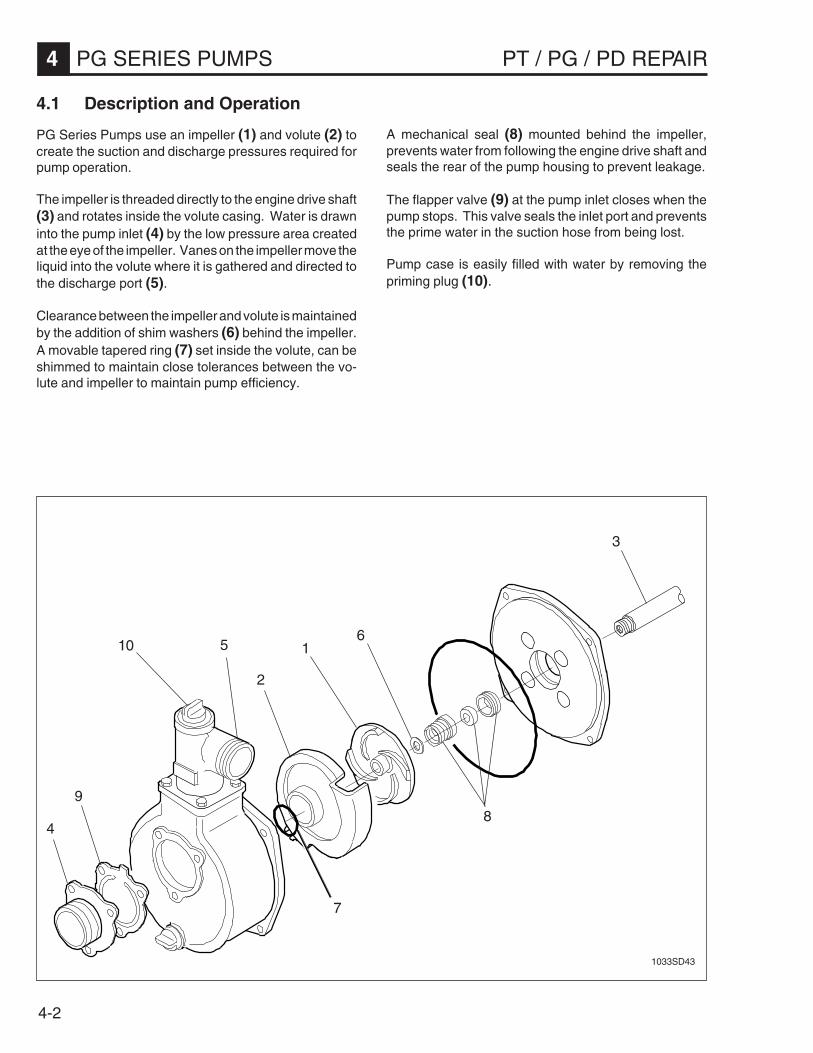
4-2
4 PG SERIES PUMPS PT / PG / PD REPAIR
4.1 Description and Operation
PG Series Pumps use an impeller (1) and volute (2) tocreate the suction and discharge pressures required forpump operation.
The impeller is threaded directly to the engine drive shaft(3) and rotates inside the volute casing. Water is drawninto the pump inlet (4) by the low pressure area createdat the eye of the impeller. Vanes on the impeller move theliquid into the volute where it is gathered and directed tothe discharge port (5).
Clearance between the impeller and volute is maintainedby the addition of shim washers (6) behind the impeller.A movable tapered ring (7) set inside the volute, can beshimmed to maintain close tolerances between the vo-lute and impeller to maintain pump efficiency.
1
1033SD43
A mechanical seal (8) mounted behind the impeller,prevents water from following the engine drive shaft andseals the rear of the pump housing to prevent leakage.
The flapper valve (9) at the pump inlet closes when thepump stops. This valve seals the inlet port and preventsthe prime water in the suction hose from being lost.
Pump case is easily filled with water by removing thepriming plug (10).
2
3
4
56
89
10
7

4-3
PT / PG / PD REPAIR PG SERIES PUMPS 4
4.2 Periodic Maintenance Schedule
The chart below lists basic pump and engine maintenance. Refer to engine manufacturer’s Operation Manual foradditional information on engine maintenance. A copy of the engine Operation Manual was supplied with the machinewhen it was shipped.
A2GP A3GP
YLIAD )gnitratSerofeB(
.leveldiulfkcehC • •
.levellioenignekcehC • •
.enignednapmupneewtebskaelroftcepsnI • •
.dedeensanaelC.renaelcriatcepsnI • •
.erawdrahlanretxenethgitdnakcehC • •
NI-KAERBENIGNEWEN ).srh02tsriF(
.retlifecalperdnalioenigneegnahC • •
SKEEW2YREVE ).srh05(
.renaelcrianaelC • •
HTNOMYREVE ).srh001(
.gulpkrapsnaelcdnakcehC • •
.puctnemidesnaelC • •
.retlifecalperdnalioenigneegnahC • •
.metsysgniloocnaelC • •
SHTNOM3YREVE ).srh003(
.secnaraelcevlavtsujdadnakcehC • •
.ecnaraelcrellepmitsujdadnakcehC • •
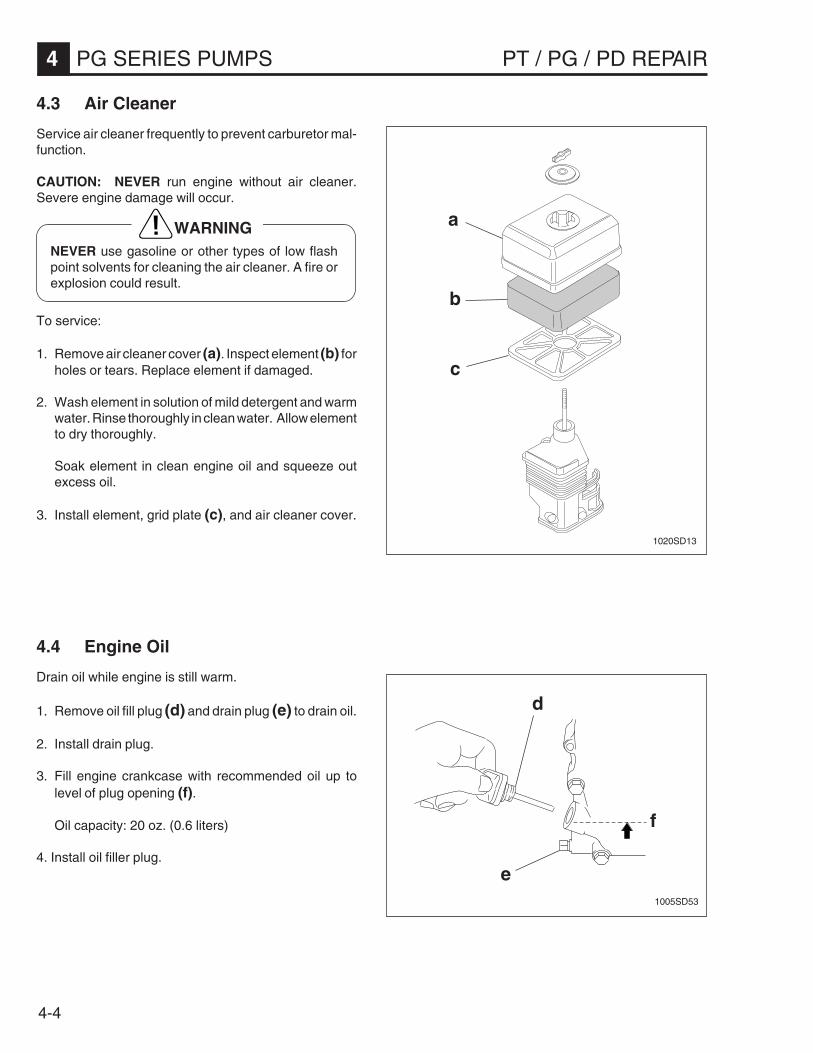
4-4
4 PG SERIES PUMPS PT / PG / PD REPAIR
4.4 Engine Oil
Drain oil while engine is still warm.
1. Remove oil fill plug (d) and drain plug (e) to drain oil.
2. Install drain plug.
3. Fill engine crankcase with recommended oil up tolevel of plug opening (f).
Oil capacity: 20 oz. (0.6 liters)
4. Install oil filler plug.
4.3 Air Cleaner
Service air cleaner frequently to prevent carburetor mal-function.
CAUTION: NEVER run engine without air cleaner.Severe engine damage will occur.
To service:
1. Remove air cleaner cover (a). Inspect element (b) forholes or tears. Replace element if damaged.
2. Wash element in solution of mild detergent and warmwater. Rinse thoroughly in clean water. Allow elementto dry thoroughly.
Soak element in clean engine oil and squeeze outexcess oil.
3. Install element, grid plate (c), and air cleaner cover.
WARNINGNEVER use gasoline or other types of low flashpoint solvents for cleaning the air cleaner. A fire orexplosion could result.
d
f
1005SD53
e
1020SD13
b
c
a
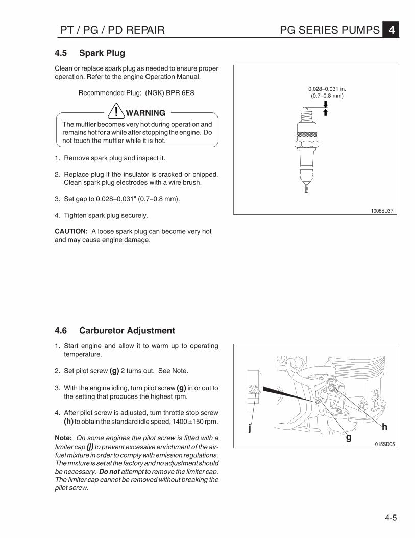
4-5
PT / PG / PD REPAIR PG SERIES PUMPS 4
4.5 Spark Plug
Clean or replace spark plug as needed to ensure properoperation. Refer to the engine Operation Manual.
Recommended Plug: (NGK) BPR 6ES
1. Remove spark plug and inspect it.
2. Replace plug if the insulator is cracked or chipped.Clean spark plug electrodes with a wire brush.
3. Set gap to 0.028–0.031" (0.7–0.8 mm).
4. Tighten spark plug securely.
CAUTION: A loose spark plug can become very hotand may cause engine damage.
WARNINGThe muffler becomes very hot during operation andremains hot for a while after stopping the engine. Donot touch the muffler while it is hot.
0.028–0.031 in.(0.7–0.8 mm)
1006SD37
4.6 Carburetor Adjustment
1. Start engine and allow it to warm up to operatingtemperature.
2. Set pilot screw (g) 2 turns out. See Note.
3. With the engine idling, turn pilot screw (g) in or out tothe setting that produces the highest rpm.
4. After pilot screw is adjusted, turn throttle stop screw(h) to obtain the standard idle speed, 1400 ±150 rpm.
Note: On some engines the pilot screw is fitted with alimiter cap (j) to prevent excessive enrichment of the air-fuel mixture in order to comply with emission regulations.The mixture is set at the factory and no adjustment shouldbe necessary. Do not attempt to remove the limiter cap.The limiter cap cannot be removed without breaking thepilot screw.
hg
j
1015SD05

4-6
4 PG SERIES PUMPS PT / PG / PD REPAIR
4.7 Cleaning Sediment Cup
Turn fuel valve off. Remove sediment cup (a) and O-ring(b). Wash them thoroughly in a nonflammable solvent.Dry them and re-install. Turn fuel valve on and check forleaks.
1001SD13
a
b
4.8 Adjusting Idle Speed
To adjust idle speed:
1. Start engine and allow it to warm up to normal operat-ing temperature.
2. Turn throttle stop screw (c) in to decrease speed, outto increase speed.
1017SD58
c
4.9 Cleaning Pump
After pumping water containing a large amount of dirt ordebris, clean out inside of pump housing.
1. Remove drain plug (d) from pump housing and drainany water left in pump.
2. Remove the four screws (e) holding the pump coverand remove cover.
3. Clean out dirt and debris. Inspect impeller and volutefor wear.
1019SD90
d
e
WARNING
The impeller may develop sharp edges. Use carewhen cleaning around impeller to prevent gettingcut.

4-7
PT / PG / PD REPAIR PG SERIES PUMPS 4
4.10 Adjusting Impeller Clearance
If it is necessary to replace impeller or volute, be sureclearance between impeller and volute is adjusted cor-rectly. The impeller (f) should be as close to the volute(g) as possible without rubbing against it. Clearance isadjusted by adding or removing shims (h) from behindimpeller. To adjust the clearance do the following:
1. Remove pump housing but do not remove impeller.
2. Measure the distance (j) of volute.
3. Measure the distance (k) of impeller.
4. Subtract the distance (k) from (j).(j) - (k) = (m) clearance.
5. The clearance between the volute and the impellershould be 0.012" (0.3 mm) to 0.028" (0.7 mm). Adjustthe distance by removing the impeller and addingshims as needed.
Each shim measures 0.012" (0.3 mm).
As the impeller wears down, additional shims may berequired to maintain the clearance between the impellerand the volute. Check the clearance whenever the me-chanical seal (n), impeller, volute, or rear flange plate arereplaced.
1019SD91
f
jk
n
hm
g
4.11 Storage
If pump is being stored for more than 30 days:
1. Remove drain plug from pump cover and drain out anywater left in the housing.
2. Remove pump cover and clean inside of pump hous-ing. Coat inside of pump with a light film of oil to reducecorrosion. A spray can of oil works well for this.
3. Tape up suction and discharge ports to prevent any-thing from falling into pump.
4. Change engine oil and follow procedures described inengine manual for engine storage.
5. Cover pump and engine and store in a clean, dry area.

4-8
4 PG SERIES PUMPS PT / PG / PD REPAIR
4.12 PG Pump Assembly
1033SD67
34
5
8
7
6 [L2]
9
10
11
12
13
17
14
15
19
[L1, T1] 18
1
2
2
16
1

4-9
PT / PG / PD REPAIR PG SERIES PUMPS 4
[L1] - 0029312 [L2] - 0029311[T1] - 16 ft.lbs. (22 Nm) [T2] - 26 ft.lbs. (37 Nm)
1 Set - plug (incl. 2) ........................................................................................22 O-ring ..........................................................................................................13 Screw
(PG2 - M8x25)(PG3 - M10x30) ..........................................................................................4
4 Port - discharge ...........................................................................................15 Gasket - discharge ......................................................................................16 Screw ..........................................................................................................3
(PG2 - M8x20)(PG3 - M10x25)
7 Port - suction ...............................................................................................18 Gasket - flapper valve .................................................................................19 Screw ..........................................................................................................4
(PG2 - M8x22)(PG3 - M10x25)
10 Housing - pump case ..................................................................................111 Ring - tapered .............................................................................................112 Volute ..........................................................................................................113 Impeller .......................................................................................................114 O-ring ..........................................................................................................115 Flange - mounting .......................................................................................116 Washer - shim .............................................................................................317 Seal - mechanical ........................................................................................118 Screw M8x60 ..............................................................................................419 Washer - seal ..............................................................................................4
REF. DESCRIPTION QTY.

4-10
4 PG SERIES PUMPS PT / PG / PD REPAIR
4.13 Inspecting Pump
Before disassembling pump, check for conditions bothoutside and inside the pump which could affect perfor-mance.
Inspecting Outside Pump:
• CHECK THAT THE PUMP IS OPERATING WITHINSPECIFICATIONS.Remember that as suction lift and discharge headincreases, pump output is reduced.
• CHECK TYPE OF FLUID BEING PUMPED.Pump will perform poorly if used to pump heavysludges or mud.
• CHECK SUCTION HOSE FOR LEAKS OR DAM-AGE.A puncture or tear above the water line will make thepump difficult or impossible to prime.
• CHECK THAT SUCTION HOSE IS CORRECT TYPE.Suction hose must have strong rigid walls. Thin-walled collapsible hoses like those used on the dis-charge side cannot be used.
• CHECK THAT STRAINER HOSE LINES ARE NOTBLOCKED OR RESTRICTED.Remove any dirt, debris or vegetation which mightinterfere with pump flow. If possible, flush hose lineswith clear water at the end of each operation andsuspend strainer in water, rather than rest on sandy ormuddy bottom. Check that discharge hose is notkinked.
• CHECK THAT ALL FITTINGS AND HOSE CLAMPSON SUCTION LINE ARE TIGHT AND SEALINGPROPERLY.Fittings and clamps may loosen during operation.Add additional clamps where necessary to ensuregood seal.
• CHECK THAT PUMP CASE WAS FILLED WITHWATER AND PRIME PLUG SEALED TIGHTLY,BEFORE START-UP.
Inspecting Inside Pump:
• CHECK FOR DEBRIS AND DIRT INSIDE PUMPCASING.If allowed to accumulate, it may restrict flow throughthe pump or impede the movement of the impeller.
• CHECK ENGINE OPERATING SPEED.3600 ±100 RPM
As engine operating RPM falls, pump capacity anddischarge head are reduced.
• CHECK FLAPPER VALVE AND INLET PORT FORLEAKS OR DAMAGE.If flapper valve is worn or distorted it may not sealtightly. Inspect threads on inlet port nipple for deepscratches which could allow air leaks.
• CHECK CLEARANCE BETWEEN IMPELLER ANDVOLUTE INSERT.Additional shims are required to maintain clearanceas impeller wears.
• CHECK PUMP HOUSING O-RING AND REARPUMP FLANGE.Replace O-Ring if torn or crushed. Make sure coveris tightened evenly. Check that rear plate is notwarped.
• CHECK FOR WATER LEAK BETWEEN PUMPHOUSING AND ENGINE. INSPECT MECHANICALSEAL LUBRICANT AND ENGINE OIL.The presence of water indicates a loose impeller boltor damage to mechanical seal.
• CHECK FOR OIL LEAK BETWEEN PUMP HOUS-ING AND ENGINE.An oil leak indicates a failed shaft seal.
• CHECK PUMP SUCTION WITH VACUUM GAUGE.If gauge reading is above 16 in. Hg (55 KPa), problemis probably outside the pump, in hose line or fitting.

4-11
PT / PG / PD REPAIR PG SERIES PUMPS 4
4.14 Flapper Valve
The flapper valve (1) is located at the pump inlet (2). During operation, this valve is open allowing a free path for waterto flow into the pump case. When the pump is stopped, it closes and prevents water in the suction line from being lost.
A leak around the flapper gasket will cause the suction line to lose its prime and make the pump difficult or impossibleto operate.
Recommended tools:Socket wrench - 1/2" (13mm)Phillips head screwdriver
1033SD69
1
2
3 4
Removal:
1. Remove three screws (3) mounting suction (inlet)port (2) to pump.
2. Remove inlet port and flapper valve assembly (1).
Installation:
3. Install new flapper valve assembly, with large washer(4) facing suction port. This washer acts as a coun-terweight and helps seal the flapper gasket againstthe pump inlet when pump stops.
4. Mount inlet port (2) to pump. Secure with screws (3)evenly until flapper gasket begins to compress. UseLoctite 243 or an equivalent medium strengththreadlocker on screws.
CAUTION: DO NOT overtighten. Overtightening maydistort flapper gasket causing an air leak at inlet port.

4-12
4 PG SERIES PUMPS PT / PG / PD REPAIR
Installation:
1. Mount pump / engine (3) to frame (4) using screws (1)and nuts (2). Apply Loctite 243 or an equivalentmedium strength threadlocker and torque to 26 ft.lbs.(35 Nm).
WARNING
Before you start the machine, ensure that all toolshave been removed from the machine and thatreplacement parts and adjusters are firmly tight-ened.
Note: See sealant and torque reference charts in backof book for appropriate threadlocking adhesives andtorque values.
4.15 Frame Assembly
1033SD70
4 2
3
1
Removal:
1. Remove four screws (1) and nuts (2) mounting pump/engine (3) to frame (4).
Recommended tools:Socket wrench - 1/2" (13mm)

4-13
PT / PG / PD REPAIR PG SERIES PUMPS 4
Removal:
1. Remove drain plug (5) from bottom of housing anddrain water from pump case.
2. Remove four screws (6) mounting pump housing (7)to the back pump flange (8).
3. Lightly tap housing with mallet to break seal andremove housing.
4. Thoroughly clean debris from pump housing (7),volute (9), and flange (8).
5. Remove volute (9) and clean O-Ring (10) and intakeport.
Recommended tools:Socket wrench - 1/2" (13mm)Rubber / Plastic mallet
4.16 Pump Housing
Installation:
1. Check clearance between impeller (11) and volute(9). Add shims as required. See Section 4.10Adjusting Impeller Clearance.
2. Inspect O-Rings (12) and (10). Grease O-Ringslightly before assembly. Make sure areas where O-Rings seat are clean.
3. Mount pump housing (7) to flange (8). Secure evenlywith screws (6). Torque to 26 ft.lbs. (37 Nm).
Note: Pump housing MUST seal flush around rearflange. Replace pump flange if it appears warped or bent.
1033SD72
7
56
8
910
11
12

4-14
4 PG SERIES PUMPS PT / PG / PD REPAIR
E-50
2
3
4
1019SD88
1 7
8
9
10
11
5
6
PE-50
3
Impeller / Mechanical Seal Assembly

4-15
PT / PG / PD REPAIR PG SERIES PUMPS 4
4.17 Impeller
CAUTION: When replacing either the impeller (1) or rear pump flange (2), make note of the I.D. numbers found onback of each component casting (3). MAKE SURE REPLACEMENT PARTS HAVE THE SAME NUMBERMARKINGS–THEY ARE NOT INTERCHANGEABLE.
Recommended tools:Socket wrench - 1/2" (13mm)Allen wrench - 6mmPlastic / rubber mallet
Removal:
1. Remove pump housing. See Section 4.16 PumpHousing.
2. Unscrew impeller (1) counterclockwise from engineshaft (4).
Note: If the impeller is hard to remove, tap it with a plasticmallet. Do not lose any adjusting shims.
3. Remove four screws (5) and washers (6) mountingrear pump flange (2) to engine.
Installation:
1. Mount rear pump flange (2) to engine. Secure withscrews (5) and washers (6). Apply Loctite 271 or anequivalent high strength threadlocker and torque to16 ft.lbs. (22 Nm)
Note: Install rear pump flange with drain channel facingdown.
2. Install mechanical seal. See Section 4.18 MechanicalSeal Replacement.
3. Screw impeller (1) clockwise onto engine shaft. DONOT apply any threadlocker to threads of impeller orengine shaft.
4.18 Mechanical Seal Replacement
Removal:
1. Remove the impeller (1). See Section 4.17 Impel-ler.
Note: Do not lose any adjusting shims (7).
2. Remove mechanical seal spring (8) and carbonface (9) from engine shaft.
3. Remove mechanical seal ceramic face (10) andL-ring (11) from rear pump flange.
Installation:
1. Clean engine shaft, remove any rust. Also cleancontact surface of ceramic and carbon faces with aclean cloth. DO NOT lubricate seal faces.
2. Place ceramic face (10) in L-ring (11) and install inpump flange.
3. Carefully place carbon face (9) and seal spring (8)on engine shaft.
4. Mount impeller to engine shaft. Turn impeller shaftclockwise to tighten.

4-16
4 PG SERIES PUMPS PT / PG / PD REPAIR
4.19 Testing
Suction Test
Required Tools:Vacuum Gauge - P/N 28755Tachometer
1. Fill pump housing with cold water until it flows out fromdischarge port.
2. Tighten pump cover and prime plug.
3. Bring engine up to operating speed. Check engineRPM. See Section 1.13 Technical Data for PG enginespeeds.
Note: Keep pump housing filled with water at all timeswhile pump is running. If too much water is lost during testprocedure, stop engine and reprime pump. It may benecessary to tilt pump or partially cover discharge port, toprevent water in the pump housing from being lost whilestill allowing air to be vented.
4. Grease mounting face of vacuum gauge (1), to en-sure a good seal. Press gauge over inlet port.
5. Gauge reading should slowly climb and then holdsteady.
6. With gauge still against inlet port, turn off engine.Gauge reading should not change.
Note: See vacuum chart for appropriate gauge read-ings.
This test MUST be completed within a few minutes toprevent the water in the pump housing from getting hot,which will result in lower readings. If possible, allow coldwater to run into discharge port while testing pump.
1033SD751033SD65
1
tnellecxE yrotcafsitaS
gH.ni)aPK(
42–02)28–86(
02–61)86–55(

4-17
PT / PG / PD REPAIR PG SERIES PUMPS 4
4.20 Troubleshooting
Reason / Remedy
1. Not enough priming water in housing.2. Engine speed too low. Adjust speed.3. Strainer plugged. Clean strainer.4. Suction hose damaged. Replace or repair hose.5. Air leak at suction port. Check that fittings are tight and
sealing properly.6. Pump too high above water.7. Debris collecting in pump housing. Clean pump housing.8. Too much clearance between impeller and volute.
1. Engine speed too low. Adjust speed.2. Suction strainer partially plugged. Clean strainer.3. Impeller worn. Adjust clearance by adding shims or
replace impeller.4. Volute worn or damaged. Adjust clearance or replace
volute.
1. Clamps are not sealing properly. Tighten, replace, or addclamp.
2. Hose diameter is too large.3. Hose is damaged.
1. Pressure may be too high for clamps being used. Addanother clamp.
2. Hose kinked or end blocked. Check hose.
1. Impeller jammed or blocked. Open pump cover and cleandirt and debris from inside of pump housing.
2. Impeller and volute binding. Adjust clearance by remov-ing shim(s) from behind impeller.
Problem / Symptom
Pump does not take in water.
Pump takes in water, little or no discharge.
Suction hose leaks at inlet.
Discharge hose does not stay on coupling.
Impeller does not turn; pump is hard tostart.

4-18
4 PG SERIES PUMPS PT / PG / PD REPAIR
Notes:

5-1
PT / PG / PD REPAIR PD SERIES PUMPS 5
Table of Contents
5.1 Description and Operation ....................................................................... 5-25.2 Periodic Maintenance Schedule .............................................................. 5-35.3 Air Cleaner .............................................................................................. 5-45.4 Engine Oil ............................................................................................... 5-45.5 Spark Plug .............................................................................................. 5-55.6 Carburetor Adjustment ............................................................................ 5-55.7 Cleaning Sediment Cup .......................................................................... 5-65.8 Adjusting Idle Speed ............................................................................... 5-65.9 Gear Case .............................................................................................. 5-65.10 Connecting Rod Bearing ......................................................................... 5-75.11 Cleaning Pump........................................................................................ 5-75.12 Storage ................................................................................................... 5-75.13 PD Pump Assembly ................................................................................ 5-85.14 Gearbox Assembly ................................................................................ 5-105.15 Inspecting Pump ................................................................................... 5-125.16 Flapper Valve ........................................................................................ 5-135.17 Diaphragm ............................................................................................ 5-145.18 Connecting Rod & Bearing .................................................................... 5-165.19 Engine ................................................................................................... 5-175.20 Gearcase .............................................................................................. 5-185.21 Testing .................................................................................................. 5-205.22 Troubleshooting .................................................................................... 5-21
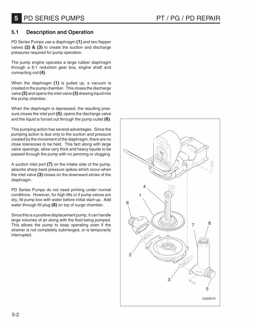
5-2
5 PD SERIES PUMPS PT / PG / PD REPAIR
5.1 Description and Operation
PD Series Pumps use a diaphragm (1) and two flappervalves (2) & (3) to create the suction and dischargepressures required for pump operation.
The pump engine operates a large rubber diaphragmthrough a 6:1 reduction gear box, engine shaft andconnecting rod (4).
When the diaphragm (1) is pulled up, a vacuum iscreated in the pump chamber. This closes the dischargevalve (2) and opens the inlet valve (3) drawing liquid intothe pump chamber.
When the diaphragm is depressed, the resulting pres-sure closes the inlet port (5), opens the discharge valveand the liquid is forced out through the pump outlet (6).
This pumping action has several advantages. Since thepumping action is due only to the suction and pressurecreated by the movement of the diaphragm, there are noclose tolerances to be held. This fact along with largevalve openings, allow very thick and heavy liquids to bepassed through the pump with no jamming or clogging.
A suction inlet port (7) on the intake side of the pump,absorbs sharp back pressure spikes which occur whenthe inlet valve (3) closes on the downward stroke of thediaphragm.
PD Series Pumps do not need priming under normalconditions. However, for high lifts or if pump valves aredry, fill pump box with water before initial start-up. Addwater through fill plug (8) on top of surge chamber.
Since this is a positive displacement pump, it can handlelarge volumes of air along with the fluid being pumped.This allows the pump to keep operating even if thestrainer is not completely submerged, or is temporarilyinterrupted.
1033SD79
1
2
3
4
7
6
5
8

5-3
PT / PG / PD REPAIR PD SERIES PUMPS 5
5.2 Periodic Maintenance Schedule
The chart below lists basic pump and engine maintenance. Refer to engine manufacturer’s Operation Manual foradditional information on engine maintenance. A copy of the engine Operation Manual was supplied with the machinewhen it was shipped.
A2TDPA2IDP
A3TDPA3IDP
YLIAD )gnitratSerofeB(
.leveldiulfkcehC • •
.levellioenignekcehC • •
.dedeensanaelC.renaelcriatcepsnI • •
.erawdrahlanretxenethgitdnakcehC • •
NI-KAERBENIGNEWEN ).srh02tsriF(
.retlifecalperdnalioenigneegnahC • •
SKEEW2YREVE ).srh05(
.renaelcrianaelC • •
.gniraebdorgnitcennocpmupesaerG • •
HTNOMYREVE ).srh001(
.gulpkrapsnaelcdnakcehC • •
.puctnemidesnaelC • •
.retlifecalperdnalioenigneegnahC • •
SHTNOM3YREVE ).srh003(
.secnaraelcevlavtsujdadnakcehC • •
.esacraegpmupnilioegnahC • •

5-4
5 PD SERIES PUMPS PT / PG / PD REPAIR
5.4 Engine Oil
Drain oil while engine is still warm.
1. Remove oil fill plug (d) and drain plug (e) to drain oil.
2. Install drain plug.
3. Fill engine crankcase with recommended oil up tolevel of plug opening (f).
Oil capacity: 21 oz. (0.6 liters)
4. Install oil filler plug.
d
f
1005SD53
e
5.3 Air Cleaner
Service air cleaner frequently to prevent carburetor mal-function.
NEVER run engine without air cleaner. Severe enginedamage will occur.
NEVER use gasoline or other types of low flash pointsolvents for cleaning the air cleaner. A fire or explosioncould result.
The engine is equipped with a dual element air cleaner.
1. Remove air cleaner cover (a). Remove both elementsand inspect them for holes or tears. Replace dam-aged elements.
2. Foam Element (b)Wash in solution of mild detergent and warm water.Rinse thoroughly in clean water. Allow element to drythoroughly.
Soak element in clean engine oil and squeeze outexcess oil.
3. Paper element (c)Tap element lightly to remove excess dirt or blowcompressed air through filter from the inside out.Replace paper element if it appears heavily soiled.
a
b
c
1001SD12

5-5
PT / PG / PD REPAIR PD SERIES PUMPS 5
5.5 Spark Plug
Clean or replace spark plug as needed to ensure properoperation. Refer to the engine Owner’s Manual.
Recommended Plug: (NGK) BPR 6ES BOSCH WR 7DC
1. Remove spark plug and inspect it.
2. Replace plug if the insulator is cracked or chipped.Clean spark plug electrodes with a wire brush.
3. Set gap to 0.028–0.031" (0.7–0.8 mm).
4. Tighten spark plug securely.
CAUTION: A loose spark plug can become very hotand may cause engine damage.
WARNINGThe muffler becomes very hot during operation andremains hot for a while after stopping the engine. Donot touch the muffler while it is hot.
0.028–0.031 in.(0.7–0.8 mm)
1006SD37
5.6 Carburetor Adjustment
1. Start engine and allow it to warm up to operatingtemperature.
2. Set pilot screw (g) 2 turns out. See Note.
3. With the engine idling, turn pilot screw (g) in or out tothe setting that produces the highest rpm.
4. After pilot screw is adjusted, turn throttle stop screw(h) to obtain the standard idle speed, 1400 ±150 rpm.
Note: On some engines the pilot screw is fitted with alimiter cap (j) to prevent excessive enrichment of the air-fuel mixture in order to comply with emission regulations.The mixture is set at the factory and no adjustment shouldbe necessary. Do not attempt to remove the limiter cap.The limiter cap cannot be removed without breaking thepilot screw.
hg
j
1015SD05

5-6
5 PD SERIES PUMPS PT / PG / PD REPAIR
5.7 Cleaning Sediment Cup
Turn fuel valve off. Remove sediment cup (a) and O-ring(b). Wash them thoroughly in a nonflammable solvent.Dry them and re-install. Turn fuel valve on and check forleaks.
1001SD13
a
b
5.8 Adjusting Idle Speed
To adjust idle speed:
1. Start engine and allow it to warm up to normal operat-ing temperature.
2. Turn throttle stop screw (c) in to decrease speed, outto increase speed.
1017SD58
c
5.9 Gear Case
Check the oil level in the gear case once a week or every25 hours of operation.
Remove oil level plug (e). Check that oil level is even withplug opening. If oil level is low, add oil through the top fillplug opening (d). Do not overfill.
Change oil in gear case once a year or every 300 hoursof operation.
Drain oil through drain plug opening (f) at bottom of gearcase. Add oil through fill plug on top of gear case.
Oil capacity: 32 oz. (1000 ml) SAE 30
d
e
f1010SD50

5-7
PT / PG / PD REPAIR PD SERIES PUMPS 5
5.12 Storage
If pump is being stored for more than 30 days:
1. Clean pump as described in Section 5.11 CleaningPump.
2. Drain out any water left in the pump housing.
3. Remove pump cover and clean inside of pump hous-ing. Spray connecting rod and inside of pump coverwith a light film of oil.
4. Tape up suction and discharge ports to prevent any-thing from falling into pump.
5. Change engine oil and follow procedures described inengine manual for engine storage.
6. Cover pump and engine and store in a clean, dry area.
5.11 Cleaning Pump
When pumping heavy sludges or water containing largeamounts of dirt and solids, clean the pump often. Ifallowed to sit in the pump and dry, these materials willharden and could damage the valves or diaphragminside the pump the next time it is used.
When cleaning pump:
1. Pump clean water through pump for a few minutesafter each use to flush dirt from inside pump andhoses.
2. Remove dirt from between engine cooling fins toprevent them from clogging up. This will preventengine from overheating.
3. Remove front cover (g) and clean dirt and greasebuild-up from connecting rod and inside of front pumpcover.
5.10 Connecting Rod Bearing
Grease connecting rod bearing once a week or every 25hours of operation.
Use a hand-operated grease gun. Add grease throughgrease fitting located behind access hole (h) provided onfront cover.
gh
1010SD51

5-8
5 PD SERIES PUMPS PT / PG / PD REPAIR
5.13 PD Pump Assembly
1015SD57
43
30
29
44
23
45
64
1
9 [T1]
10
46
1112
1214
1513
12
14
15
738
18
16
1713
[T2] 27
28
20
21
1922
23
2425
[L1, T3] 3435
3637
38
39
40
41
42
32
33
36
38
39
[T3] 35
37
40
45
34 [L1, T3]
31
26
47
26 [T2]

5-9
PT / PG / PD REPAIR PD SERIES PUMPS 5
[L1] - (0026695)[T1] - 55–60 ft.lbs. (75–81 Nm) [T2] - 35–40 ft.lbs. (48–54 Nm) [T3] - 16–20 ft.lbs. (22–27 Nm)
1 Cover - gearbox ..........................................................................................12 Fitting - grease ............................................................................................13 Screw #10-32x1/2 .......................................................................................64 Washer - retaining .......................................................................................25 Connecting rod ............................................................................................16 Bearing - cam follower ................................................................................17 Crank - arm .................................................................................................18 Seal - oil ......................................................................................................19 Screw 1/2x1-1/2 ..........................................................................................110 Setscrew .....................................................................................................111 Screw 5/16-18x2 .........................................................................................212 Washer 5/16 ................................................................................................613 Shim - engine ..............................................................................................814 Washer - lock 5/16 ......................................................................................415 Nut 5/16 ......................................................................................................416 Screw 5/16-18x2-1/4 ...................................................................................217 Bracket - bumper ........................................................................................118 Screw ..........................................................................................................219 Bracket ........................................................................................................120 Washer - lock ..............................................................................................221 Nut ..............................................................................................................222 Axle .............................................................................................................123 Wheel ..........................................................................................................224 Washer .......................................................................................................225 Pin - cotter ...................................................................................................226 (PD2) Stud ..................................................................................................3
(PD3) Bolt - carriage ...................................................................................327 Screw 1/2x2-1/4 ..........................................................................................428 Screw #10-24x1/2 .......................................................................................229 Housing - pump case ..................................................................................130 Diaphragm - TPE, (standard) ......................................................................131 Diaphragm - rubber, (optional) ....................................................................132 Plug 2", priming ...........................................................................................133 Port - suction (inlet) .....................................................................................134 Fitting - NPT ................................................................................................135 Washer - lock (incl. 36) ...............................................................................436 Screw #10-32x1/2 .......................................................................................437 Weight - retainer valve ................................................................................238 Gasket - flapper valve .................................................................................239 Weight - flapper valve .................................................................................240 Pin 1/8x3/8, spring ......................................................................................241 Washer - lock ..............................................................................................442 Nut 1/2 ........................................................................................................443 Housing - water box ....................................................................................144 Handle - towing pole ...................................................................................145 Flange - discharge ......................................................................................146 Nut - lock .....................................................................................................147 Axle - stub ...................................................................................................2
REF. DESCRIPTION QTY.

5-10
5 PD SERIES PUMPS PT / PG / PD REPAIR
1015SD56
4
3
2
7
6
5
8
9
101112 [T1]
15
14
11
13
14 28 [T3]
2625
24
23
19 [T2]
1617
2221
20
27
1
18
29
5.14 Gearbox Assembly

5-11
PT / PG / PD REPAIR PD SERIES PUMPS 5
[T1] - 55–60 ft.lbs. (75–81 Nm) [T2] - 10–11 ft.lbs. (14–15 Nm)[T3] - 7–8 ft.lbs. (9.5–11 Nm)
1 Screw 1/2-13x2-1/2 (incl. washer) ..............................................................22 Gearbox ......................................................................................................13 Plug - oil 3/8-18 ...........................................................................................14 Gasket - gearbox ........................................................................................15 Bearing........................................................................................................16 Key - woodruff .............................................................................................27 Gear ............................................................................................................18 Shaft - gear .................................................................................................19 Gear - internal .............................................................................................110 Gear - pinion ...............................................................................................111 Bearing........................................................................................................212 Screw 1/2-13x1-3/4 (incl. washer) ..............................................................213 Bearing........................................................................................................114 Pin 1/4x3/4, dowel .......................................................................................215 Cover ..........................................................................................................116 Hook - lifting ................................................................................................117 Screw 1/4x1-1/4 (incl. lock washer) ............................................................218 Key..............................................................................................................119 Screw 5/16-18x1 (incl. lock washer) ...........................................................420 Adapter - engine ..........................................................................................121 O-Ring ........................................................................................................122 Retaining Ring .............................................................................................123 Screw 5/16-24x1 (incl. lock washer) ...........................................................424 Bearing........................................................................................................125 Gear - pinion ...............................................................................................126 Bearing - needle ..........................................................................................127 Plug - oil 1/8 NPT ........................................................................................228 Screw 1/4x1 (incl. lock washer) ..................................................................929 Handle - towing pole ...................................................................................1
REF. DESCRIPTION QTY.

5-12
5 PD SERIES PUMPS PT / PG / PD REPAIR
5.15 Inspecting Pump
Before disassembling pump, check for conditions bothoutside and inside the pump which could affect perfor-mance.
Inspecting Outside Pump:
• CHECK THAT THE PUMP IS OPERATING WITHINSPECIFICATIONS.Remember that as suction lift and discharge headincreases, pump output is reduced. On the PD SeriesPumps, discharge head CANNOT exceed 25' (7.6m).
• CHECK TYPE OF FLUID BEING PUMPED.Although the PD Series Pumps are designed to handleheavy sludges and muddy water, the mixture must befluid enough to flow freely.
• CHECK SUCTION HOSE FOR LEAKS OR DAM-AGE.A puncture or tear above the water line will make thepump difficult or impossible to prime.
• CHECK THAT SUCTION HOSE IS CORRECT TYPE.Suction hose must have strong rigid walls. Thin-walled collapsible hoses like those used on the dis-charge side cannot be used.
• CHECK THAT STRAINER HOSE LINES ARE NOTBLOCKED OR RESTRICTED.Remove any dirt, debris or vegetation which mightinterfere with pump flow. If possible, flush hose lineswith clear water at the end of each operation andsuspend strainer in water, rather than rest on sandy ormuddy bottom. Check that discharge hose is notkinked.
• CHECK THAT ALL FITTINGS AND HOSE CLAMPSON SUCTION LINE ARE TIGHT AND SEALINGPROPERLY.Fittings and clamps may loosen during operation.Add additional clamps where necessary to ensuregood seal.
• CHECK THAT SUCTION HOSE RUNS EVEN WITHOR DOWN HILL FROM PUMP.If the suction line is elevated above pump inlet, backpressure in the hose may prevent pump inlet valvefrom sealing. Discharge rate is reduced.
• CHECK THAT PRIME PLUG IS TIGHT. PRIME FORHIGH LIFTS OR WHEN VALVE RUBBERS AREDRY, TO IMPROVE SUCTION UPON INITIALSTART-UP.
Inspecting Inside Pump:
• CHECK THAT BOLTS AROUND DIAPHRAGM ARESECURE AND TIGHTENED EVENLY.A loose bolt will prevent a good seal around gasket.
• CHECK ENGINE OPERATING SPEED.3000 ±100 RPM
As engine operating RPM falls, pump capacity anddischarge head are reduced.
• CHECK FLAPPER VALVE AND INLET PORT FORLEAKS OR DAMAGE.If flapper valve is worn or distorted it may not sealtightly. Inspect threads on inlet port nipple for deepscratches which could allow air leaks.
• CHECK FOR DEBRIS AND DIRT INSIDE PUMPCASING.Dirt and debris trapped under the diaphragm mayinterfere with its operation. This may occur if a strainerwas not attached to the suction line, allowing largeparticles to enter the pump box. Always attach astrainer to suction hose.
Large solids can also form under the diaphragm, ifsludge or mud from last application is allowed toharden in pump box without being flushed.
• CHECK DIAPHRAGM FOR CRACKS, PUNCTURESOR TEARS.A damaged diaphragm will not produce sufficientsuction or discharge pressure.
• CHECK PUMP SUCTION WITH VACUUM GAUGE.If gauge reading is above 16 in. Hg (55 KPa), problemis probably outside the pump, in hose line or fitting.

5-13
PT / PG / PD REPAIR PD SERIES PUMPS 5
5.16 Flapper Valve
Recommended tools:Socket wrench - 3/8"Screwdriver
1033SD82
1
2
Removal:
1. Remove two screws (1) and washers (2) mountingeither the suction (inlet) port (3) or discharge port (4)to pump water box (5).
2. Remove flapper valves (6).
3. Remove large weights (7) and small weights (8) fromeach side of flapper valve.
Installation:
1. Install new flapper valve assembly, with small weight(8) toward intake side of each valve.
2. Tighten screws (9) on valve weights until rubberbegins to compress.
CAUTION: DO NOT overtighten. Overtightening maydistort rubber gasket, preventing it from sealing properly.
3. Use dowel pins (10) on pump water box (5) andposition flapper valves.
4. Mount suction (inlet) port (3) or discharge port (4) topump using screws (1) and washers (2). Torque to16–20 ft.lbs (22–27 Nm).
CAUTION: DO NOT overtighten. Overtightening maydistort flapper gasket causing an air leak at inlet port.
12
3
10
98
6
7
5
10
8
7
6
9
4
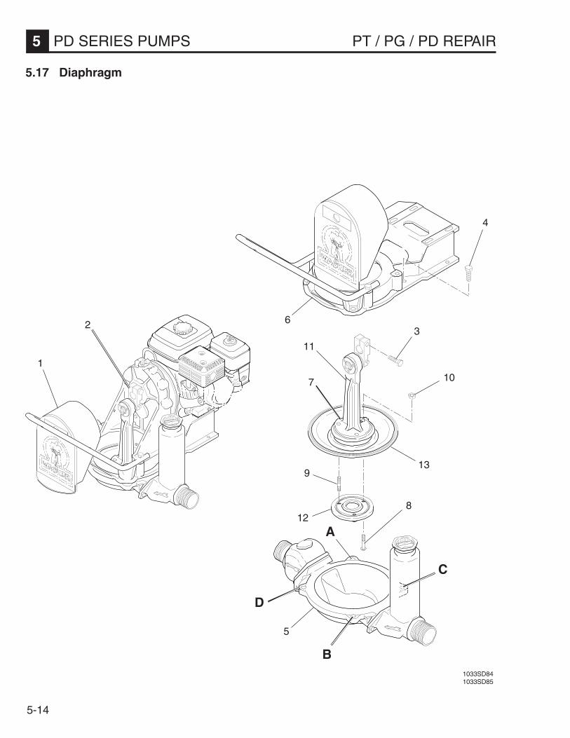
5-14
5 PD SERIES PUMPS PT / PG / PD REPAIR
1
5.17 Diaphragm
23
4
10
11
6
7
139
812
5
C
A
B
D
1033SD841033SD85

5-15
PT / PG / PD REPAIR PD SERIES PUMPS 5
5.17 Diaphragm (cont.)
Recommended tools:Socket wrench - 3/4"ScrewdriverPry bar
Removal:
1. Remove connecting rod cover (1).
2. With stop switch against spark plug, pull starter untilcrank arm (2) is in its uppermost position.
3. Loosen screw (3) mounting crank arm to gear shaft.See Section 5.20 Gearcase.
4. Remove four screws (4) mounting water box (5) topump frame (6).
5. Lower water box assembly (5) from pump frame (6)and remove connecting rod / diaphragm assembly(7).
6. Remove three screws (8) or studs (9) and nuts (10)mounting connecting rod (11) and mounting plate(12) to diaphragm (13).
Installation:
1. Position new diaphragm (13) in between mountingplate (12) and connecting rod (11). Secure witheither screws (8) or studs (9) and nuts (10). Torquenuts to 35–40 ft. lbs. (48–54 Nm).
2. Mount crank arm (2) to gear shaft. Secure with screw(3) and torque to 55–60 ft. lbs. (75–81 Nm).
3. Carefully position connecting rod / diaphragm assem-bly (7) between pump frame (6) and water boxassembly (5). Secure with four screws (4). Torquescrews to 23 ft. lbs. (32 Nm.)
CAUTION: Tighten bolts evenly, in progressive stepsA-B-C &D, to ensure a tight seal around diaphragm.When assembled correctly, diaphragm should be com-pressed to approx. 3/8" (9.5 mm) around entire circum-ference.
4. Replace crank arm cover (1).

5-16
5 PD SERIES PUMPS PT / PG / PD REPAIR
5.18 Connecting Rod & Bearing
Recommended tools:Socket wrench 1-1/8"Allenwrench 5/32"Screwdriver
Removal:
1. Remove connecting rod / diaphragm assembly. SeeSection 5.17 Diaphragm.
2. Remove crank arm retaining nut (1).
3. Loosen crank arm setscrew (2) .
4. Remove three screws (3) mounting retaining wash-ers (4) to both sides of connecting rod (5).
5. Support connecting rod (5) in an arbor press. Presson threaded end of bearing cam (6) to remove it.
CAUTION: When bearing shaft is pressed out of crankarm, 25 bearing needles (9) will be free, and may fall outof the bearing race. If the bearing is to be reused, usecare to avoid losing any bearing needles. DO NOT presson grease fitting (7) in bearing shaft!
Installation:
1. Insert bearing needles (9) into connecting rod (5).
Note: Use grease to hold needles in place during instal-lation.
2. Insert bearing cam (6) into connecting rod.
3. Mount retaining washers (4) to both sides of connect-ing rod using three screws (3).
4. Support bearing shaft in arbor press and press crankarm (8) onto bearing shaft. Secure crank arm usingsetscrew (2) and nut (1).
5. Before mounting connecting rod / diaphragm assem-bly, scrape edges around diaphragm clean. SeeSection 5.17 Diaphragm for installation procedure.
4. After asssembly, grease bearing with Shell Alvania#2 through fitting (7).
1033SD86
7
4
53
6
3
4
2
8
19

5-17
PT / PG / PD REPAIR PD SERIES PUMPS 5
5.19 Engine
Recommended tools:Socket wrench - 1/2" (13mm)
Removal:
1. Remove drain plug (1) from bottom of gearbox anddrain oil. Install plug back into gearbox.
2. Remove four screws (2) and lock washers (3) mount-ing engine adapter (4) to engine (5).
3. Remove two screws (6), washers (7), lock washers(8), and nuts (9) mounting bumper bracket (10) andrear part of engine to pump housing.
4. Remove two screws (11), four washers (7), two lockwashers (8), and nuts (9) mounting front part ofengine to pump housing.
5. Pull engine away from gearbox until engine shaft isclear of engine adapter (4).
Note: When removing engine, keep in mind there areshims (12) between pump housing and engine. DO NOTthrow away shims. They are to be reused when mountingengine to pump housing.
Installation:
1. Position engine (5) on pump housing.
Note: Turn engine shaft to align key (13) with keyway inengine adapter (4).
2. Slide engine into gearbox.
3. Mount engine (5) to engine adapter (4) using fourscrews (2) and lock washers (3).
4. Mount front part of engine to pump housing using twoscrews (11), four washers (7), two lock washers (8),and nuts (9).
Note: Place two shims (12) as shown between engineand pump housing prior to tightening mounting hard-ware. Also note configuration of hardware.
5. Mount rear part of engine and bumper bracket (10) topump housing using two screws (6), washers (7),lock washers (8), and nuts (9).
6. After installation, make sure drain plug (1) is installedand fill gearbox with oil. See Section 1.14 TechnicalData (PD2/PD3) for lubrication specifications.
1
2
3
413
5
610
9
8
7
12
117
89
12
1033SD99
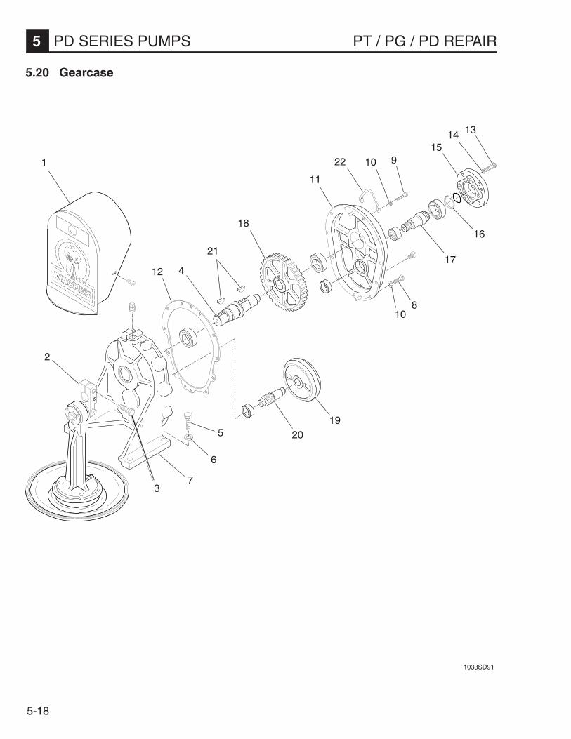
5-18
5 PD SERIES PUMPS PT / PG / PD REPAIR
5.20 Gearcase
1033SD91
1
2
3
4
5
6
7
910
11
810
12
131415
16
17
18
1920
21
22
5-19
PT / PG / PD REPAIR PD SERIES PUMPS 5
Removal:
1. Remove engine from pump housing. See Section5.19 Engine.
2. Remove connecting rod cover (1).
3. With stop switch against spark plug, pull starter untilcrank arm (2) is in its uppermost position.
4. Loosen screw (3) mounting crank arm (2) to gearshaft (4). Pry crank arm off gear shaft.
5. Remove four screws (5) and lock washers (6) mount-ing gearbox (7) to pump housing.
6. Lift gearbox from pump housing.
7. Remove nine screws (8), two screws (9), and lockwashers (10) mounting gearbox cover (11) to gear-box (7).
CAUTION: When separating the cover from gearbox,be careful not to damage gasket (12).
8. Remove four screws (13) and lock washer (14)mounting engine adapter (15) to gearbox cover (11).
9. Remove retaining ring (16) and pull pinion gear (17)from gearbox cover.
10. Pull gear (18) and shaft (4) from gearbox (7).
11. Pull internal gear (19) and pinion gear (20) fromgearbox (7).
5.20 Gearcase (cont.)
Recommended tools:Socket wrench - 7/16"Pry barAllen wrench - 1/4"
Installation:
1. Inspect all gaskets, seals, and bearings betweenpump components and replace if necessary.
2. Press pinion gear (20) and internal gear (19) intogearbox (7).
3. Align keys on shaft (21) with slots in gearbox and gear(18) and press into gearbox.
4. Align pinion gear (17) and press into gearbox cover(11). Install retaining ring (16).
5. Mount engine adapter (15) to gearbox cover usingfour screws (13) and lock washers (14). Torquescrews to 10–11 ft.lbs. (14–15 Nm).
6. Mount gearbox cover (11) to gearbox (7) using ninescrews (8) and lock washers (10). Torque screws to7–8 ft.lbs. (9.5–11 Nm).
7. Mount lifting bracket (22) to gearbox cover (11) usingtwo screws (9) and lock washers (10).
8. Mount gearbox assembly to pump housing using fourscrews (5) and lock washers (6). Torque screws to55–60 ft.lbs. (75–81 Nm).
9. Mount crank arm (2) to gear shaft (4). Secure withscrew (3) and torque to 55–60 ft. lbs. (75–81 Nm).
10. Install engine to gearbox and pump housing. SeeSection 5.19 Engine.
11. Mount connecting rod cover (1).

5-20
5 PD SERIES PUMPS PT / PG / PD REPAIR
5.21 Testing
Suction Test
Required Tools:Vacuum Gauge - P/N 28755Tachometer
1. Check that mounting hardware for diaphragm andvalves are tight.
2. If valves are dry, run pump for a few minutes whileadding water through prime plug in suction chamber.This will wet rubber gaskets in valves and provide abetter seal while testing.
3. Replace prime plug and tighten.
4. Bring engine up to operating speed. Check engineRPM.
3000 ±100 RPM
5. Grease mounting face of vacuum gauge (1), to en-sure a good seal. Press gauge over inlet port.
Note: It is not necessary to keep water in the pump casewhile testing diaphragm pumps. This pump design doesnot use a mechanical seal, which requires water in thepump case to keep seal surfaces cool.
6. Gauge reading will fluctuate slightly as connecting rodoperates diaphragm.
A HIGH reading of 16 in.Hg (55 KPa) is good.
The pump may operate satisfactorily even at readingsless than this. The valve’s rubber gaskets seal betterwhile pump is actually working.
1034SD041033SD65
1

5-21
PT / PG / PD REPAIR PD SERIES PUMPS 5
5.22 Troubleshooting
Problem / Symptom
Engine does not start.
Engine starts but pump does nottake in water.
Pump output low.
Reason / Remedy
1. Engine problem. See engine manufacturer’s service manual fortroubleshooting and repair.
2. Engine oil level too low. Add oil to engine.
3. Pump housing filled with dirt and debris. Disassemble andclean inside of pump.
4. Pump gear case damaged. Inspect and repair.
1. Pump is located too high above or too far away from water.Locate pump closer to water.
2. Air leak on suction side of pump. Check that hose fittings andcap on surge chamber are tight and sealing properly.
3. Suction hose damaged or collapsed. Repair or replace hose.
4. Strainer plugged. Clean or replace strainer.
5. Dirt collecting inside pump and hoses, blocking flow. Cleaninside of pump and flush hoses.
6. Engine running slow. Check engine speed and adjust. See“Technical Data” for engine speed.
7. Pump valves damaged or not seating properly. Check forstones and gravel embedded in valves. Replace valves.
8. Diaphragm loose or damaged. Inspect diaphragm for damage.Replace and tighten.
1. Pump located too high above or too far away from water. Locatepump closer to water.
2. Suction strainer or intake line partially plugged. Clean hose lineand strainer.
3. Discharge hose is kinked or end is blocked. Check that hose liesstraight and flows freely.
4. Discharge hose too narrow. Use hose of equal diameter orlarger than suction hose.

5-22
5 PD SERIES PUMPS PT / PG / PD REPAIR
Notes:

Use Of Threadlockers and Sealants
Threadlocking adhesives and sealants are specified throughout this manual and should be used where indicated.Threadlocking compounds normally break down at temperatures above 350° F (175° C). If a screw or bolt is hardto remove, heat it using a small propane torch to break down sealant. When applying sealants, follow instructionson container. The sealants listed below are recommended for use on WACKER equipment.
SEALANTS
TYPE( ) = Europe COLOR USAGE PART NO. - SIZE
Loctite 222 Purple Low strength, for locking threads smaller than 1/4" (6 mm). 73287 - 10 mlHernon 420 Hand tool removable.Omnifit 1150 (50M) Temp. range, -65 to 300 degrees F (-54 to 149 degrees C)
Loctite 243 Blue Medium strength, for locking threads larger than 1/4" (6 mm). 29311 - .5 mlHernon 423 Hand tool removable. 17380 - 50 mlOmnifit 1350 (100M) Temp. range, -65 to 300 degrees F (-54 to 149 degrees C)
Loctite 271 / 277 Red High strength, for all threads up to 1" (25 mm). 29312 - .5 mlHernon 427 Heat parts before disassembly. 26685 - 10 mlOmnifit 1550 (220M) Temp. range, -65 to 300 degrees F (-54 to 149 degrees C) 73285 - 50 ml
Loctite 290 Green Medium to high strength, for locking preassembled threads 28824 - .5 mlHernon 431 and for sealing weld porosity (wicking). 25316 - 10 mlOmnifit 1710 (230LL) Gaps up to 0.005" (0.13 mm)
Temp. range, -65 to 300 degrees F (-54 to 149 degrees C)
Loctite 609 Green Medium strength retaining compound for slip or press fit 29314 - .5 mlHernon 822 of shafts, bearings, gears, pulleys, etc.Omnifit 1730 (230L) Gaps up to 0.005" (0.13 mm)
Temp. range, -65 to 300 degrees F (-54 to 149 degrees C)
Loctite 545 Brown Hydraulic sealant 79356 - 50 mlHernon 947 Temp. range, -65 to 300 degrees F (-54 to 149 degrees C)Omnifit 1150 (50M)
Loctite 592 White Pipe sealant with Teflon for moderate pressures. 26695 - 6 mlHernon 920 Temp. range, -65 to 300 degrees F (-54 to 149 degrees C) 73289 - 50 mlOmnifit 790
Loctite 515 Purple Form-in-place gasket for flexible joints. 70735 - 50 mlHernon 910 Fills gaps up to 0.05" (1.3 mm)Omnifit 10 Temp. range, -65 to 300 degrees F (-54 to 149 degrees C)
Loctite 496 Clear Instant adhesive for bonding rubber, metal and plastics;Hernon 110 general purpose. 52676 - 1 oz.Omnifit Sicomet 7000 For gaps up to 0.006" (0.15 mm)
Read caution instructions before using.Temp. range, -65 to 180 degrees F (-54 to 82 degrees C)
Loctite Primer T Aerosol Fast curing primer for threadlocking, retaining and 2006124 - 6 oz.Hernon Primer 10 Spray sealing compounds. Must be used with stainless steelOmnifit VC Activator hardware. Recommended for use with gasket sealants.

Size Ft.Lb. Nm Ft.Lb. Nm Ft.Lbs. Nm Inch Metric Inch Metric
No.4 *6 0.7 *14 1.0 *12 1.4 1/4 5.5 3/32 -
No.6 *12 1.4 *17 1.9 *21 2.4 5/16 8 7/64 -
No.8 *22 2.5 *31 3.5 *42 4.7 11/32 9 9/64 -
No.10 *32 3.6 *45 5.1 *60 6.8 3/8 - 5/32 -
1/4 6 8.1 9 12 12 16 7/16 - 3/32 -
5/16 13 18 19 26 24 33 1/2 13 1/4 -
3/8 23 31 33 45 43 58 9/16 - 5/16 -
7/16 37 50 52 71 69 94 5/8 16 3/8 -
1/2 57 77 80 109 105 142 3/4 19 3/8 -
9/16 82 111 115 156 158 214 13/16 - - -
5/8 112 152 159 216 195 265 15/16 24 1/2 -
3/4 200 271 282 383 353 479 1-1/8 - 5/8 -
1 Ft.Lb. = 1.357 Nm 1 Inch = 25.4 mm* = In.Lb.
Metric Fasteners (DIN)
Inch Fasteners (SAE)
Size Ft.Lb. Nm Ft.Lb. Nm Ft.Lbs. Nm Inch Metric Inch Metric
M3 *11 1.2 *14 1.6 *19 2.1 7/32 5.5 - 2.5
M4 *26 2.9 *36 4.1 *43 4.9 9/32 7 - 3
M5 *53 6.0 6 8.5 7 10 5/16 8 - 4
M6 7 10 10 14 13 17 - 10 - 5
M8 18 25 26 35 30 41 1/2 13 - 6
M10 36 49 51 69 61 83 11/16 17 - 8
M12 63 86 88 120 107 145 3/4 19 - 10
M14 99 135 140 190 169 230 7/8 22 - 12
M16 155 210 217 295 262 355 15/16 24 - 14
M18 214 290 298 405 357 485 1-1/16 27 - 14
M20 302 410 427 580 508 690 1-1/4 30 - 17
8.8 10.9
TORQUE VALUES (Based on Bolt Size and Hardness) WRENCH SIZE
12.9 12.910.98.8
TORQUE VALUES
SAE 5 SAE 8


Wacker Construction Equipment AG · Preußenstraße 41 · D-80809 München · Tel.: +49-(0)89-354 02 - 0 · Fax: +49 - (0)89-354 02-390Wacker Corporation · P.O. Box 9007 · Menomonee Falls, WI 53052-9007 · Tel. : +1-(1)(262) 255-0500 · Fax: +1-(1)(262) 255-0550 · Tel. : (800) 770-0957Wacker Asia Pacific Operations · Sunley Center, Unit 912, 9/F · 9 Wing Qin Street, Kwai Chung, N.T. · Hong Kong · Tel. + 852 2406 60 32 · Fax: + 852 2406 60 21