ps scale quick start guide see back for detailed ... · ps scale quick start guide see back for...
TRANSCRIPT

PS Scale Quick Start Guide Models PS90See back for detailed instructions and FAQ
Verify Contents:
Level Scale
Power Supply& RS232 Cable
For Serial (RS232) connection to PC
USB CableFor USB Connection to
PC
Plug USB cable into scale and PC. Go to step 8.
PC Connectors
Plug RS232 cable into scale and PC.Plug in Power Supply.Go to step 8.
Pull Shipping Tabs!! Observe display on first power up !!
Press repeatedly to scroll through codes. Numbers will repeat.Select correct code by pressing twice.Scale will reboot and display should read “ ”.
ACOutlet
Confirm Connection
Put Platter on Scale
Adjust feet until scale is stable and bubble is centered.Tighten lock nut.
Display & BracketPadCableClips
PlatterShipped in separate box
Scale Base
Use a screw-driver to gently pry apart scale base until tabs become loose.
Install Display
To Base Mount: Attach display to base by inserting two plastic clips at yellow arrows, turn 90° to lock in position.
Insert Clips
Display can be wall or base mounted.
Connect display cable at 2 red arrows. Wrap excess cable beneath scale.Adjust the display angle.
Remove 4 red shipping tabs from scale base and discard.
6
Turn to Lock
Correct Level
Incorrect
USB connection preferred if supported by shipping software
Use RS232 connection if USB is
not available For additional product and technical support:
If “ ” is displayed, no code is required. Go to step 9.If “ ” is displayed, enter two digit GeoCal Location Code for your area from the chart on the back.
Open your carrier, shipping, or POS software on the PC.In the shipping software setup screen, select the proper scale model from the pull down list (e.g., “Toledo PS60”).For additional assistance, contact your software provider.
Units Indicator
Zero: Zero scale with no weight on platter
Units: Switch between units( )
Zero Indicator
Scale Over CapacityReduce weight
Scale Under CapacityZero scale with no weight on platter
I/O
Make direct USB connection to PC.
Do not use USB Hub.
PC Connectors
- OR -
To Wall Mount: Remove adhesive liner from pad and insert into bracket. Remove outside liner and position on wall. Press firmly to secure.
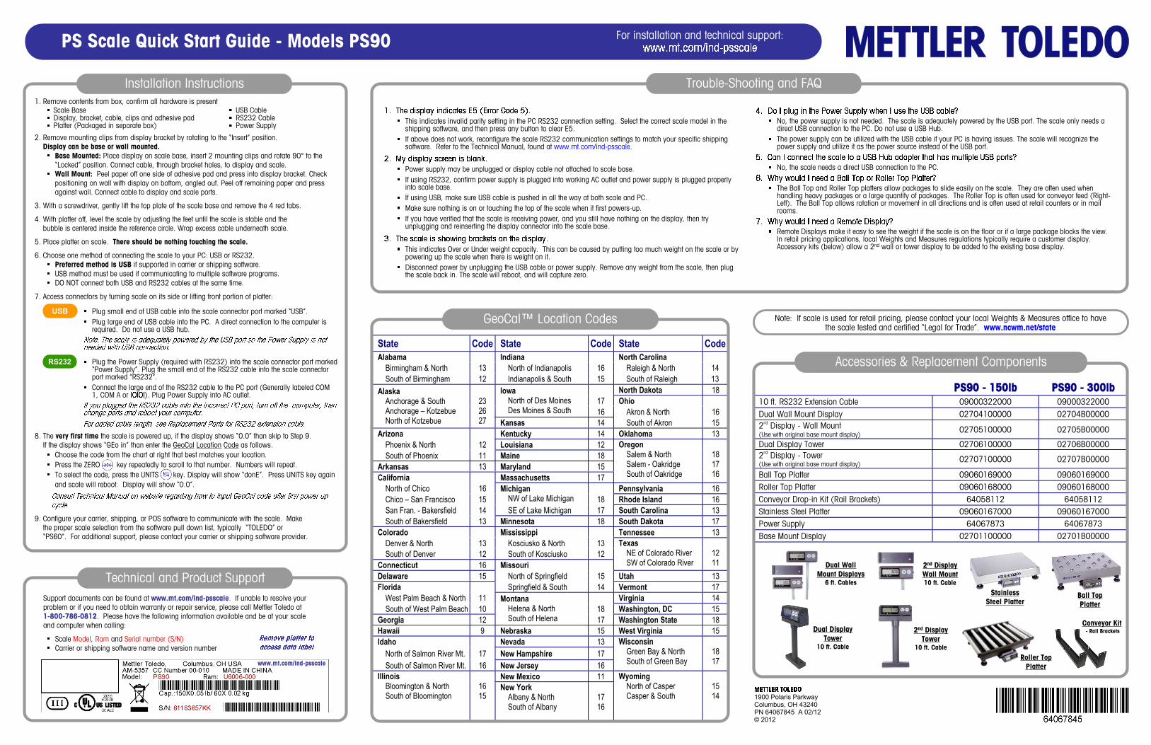
PS90 - 150lb PS90 - 300lb 10 ft. RS232 Extension Cable 09000322000 09000322000 Dual Wall Mount Display 02704100000 02704B00000 2nd Display - Wall Mount (Use with original base mount display) 02705100000 02705B00000
Dual Display Tower 02706100000 02706B00000 2nd Display - Tower (Use with original base mount display) 02707100000 02707B00000
Ball Top Platter 09060169000 09060169000 Roller Top Platter 09060168000 09060168000 Conveyor Drop-in Kit (Rail Brackets) 64058112 64058112 Stainless Steel Platter 09060167000 09060167000 Power Supply 64067873 64067873 Base Mount Display 02701100000 02701B00000
State Code State Code State Code Alabama Indiana North Carolina Birmingham & North 13 North of Indianapolis 16 Raleigh & North 14 South of Birmingham 12 Indianapolis & South 15 South of Raleigh 13
North Dakota 18 17 Ohio
Iowa North of Des Moines Des Moines & South 16 Akron & North 16
Alaska Anchorage & South Anchorage – Kotzebue North of Kotzebue
23 26 27 Kansas 14 South of Akron 15
Arizona Kentucky 14 Oklahoma 13 Phoenix & North 12 Louisiana 12 South of Phoenix 11 Maine 18 Arkansas 13 Maryland 15 California Massachusetts 17
Oregon Salem & North Salem - Oakridge South of Oakridge
18 17 16
North of Chico 16 Pennsylvania 16 Chico – San Francisco 15
Michigan NW of Lake Michigan 18 Rhode Island 16
San Fran. - Bakersfield 14 SE of Lake Michigan 17 South Carolina 13 South of Bakersfield 13 Minnesota 18 South Dakota 17 Colorado Mississippi Tennessee 13 Denver & North 13 Kosciusko & North 13 South of Denver 12 South of Kosciusko 12 Connecticut 16 Missouri
Texas NE of Colorado River SW of Colorado River
12 11
Delaware 15 North of Springfield 15 Utah 13 Florida Springfield & South 14 Vermont 17 West Palm Beach & North 11 Virginia 14 South of West Palm Beach 10 18 Washington, DC 15 Georgia 12
Montana Helena & North South of Helena 17 Washington State 18
Hawaii 9 Nebraska 15 West Virginia 15 Idaho Nevada 13 North of Salmon River Mt. 17 New Hampshire 17 South of Salmon River Mt. 16 New Jersey 16
Wisconsin Green Bay & North South of Green Bay
18 17
New Mexico 11 Illinois Bloomington & North South of Bloomington
16 15
New York Albany & North South of Albany
17 16
Wyoming North of Casper Casper & South
15 14
PS Scale Quick Start Guide - Models PS90 For installation and technical support:
Installation Instructions
Technical and Product Support
Note: If scale is used for retail pricing, please contact your local Weights & Measures office to have the scale tested and certified “Legal for Trade”. www.ncwm.net/state
This indicates invalid parity setting in the PC RS232 connection setting. Select the correct scale model in the shipping software, and then press any button to clear E5.If above does not work, reconfigure the scale RS232 communication settings to match your specific shipping software. Refer to the Technical Manual, found at www.mt.com/ind-psscale.
Power supply may be unplugged or display cable not attached to scale base.If using RS232, confirm power supply is plugged into working AC outlet and power supply is plugged properly into scale base.If using USB, make sure USB cable is pushed in all the way at both scale and PC.Make sure nothing is on or touching the top of the scale when it first powers-up.If you have verified that the scale is receiving power, and you still have nothing on the display, then try unplugging and reinserting the display connector into the scale base.
This indicates Over or Under weight capacity. This can be caused by putting too much weight on the scale or by powering up the scale when there is weight on it.Disconnect power by unplugging the USB cable or power supply. Remove any weight from the scale, then plug the scale back in. The scale will reboot, and will capture zero.
No, the power supply is not needed. The scale is adequately powered by the USB port. The scale only needs a direct USB connection to the PC. Do not use a USB Hub.The power supply can be utilized with the USB cable if your PC is having issues. The scale will recognize the power supply and utilize it as the power source instead of the USB port.
No, the scale needs a direct USB connection to the PC.
The Ball Top and Roller Top platters allow packages to slide easily on the scale. They are often used when handling heavy packages or a large quantity of packages. The Roller Top is often used for conveyor feed (Right-Left). The Ball Top allows rotation or movement in all directions and is often used at retail counters or in mail rooms.
Remote Displays make it easy to see the weight if the scale is on the floor or if a large package blocks the view. In retail pricing applications, local Weights and Measures regulations typically require a customer display. Accessory kits (below) allow a 2nd wall or tower display to be added to the existing base display.
Trouble-Shooting and FAQ
1900 Polaris ParkwayColumbus, OH 43240PN 64067845 A 02/12© 2012
Accessories & Replacement Components
Dual Wall Mount Displays
6 ft. Cables
2nd Display Wall Mount10 ft. Cable
2nd Display Tower
10 ft. Cable
Ball TopPlatter
Dual Display Tower
10 ft. Cable
1. Remove contents from box, confirm all hardware is present
2. Remove mounting clips from display bracket by rotating to the “Insert” position. Display can be base or wall mounted.
Base Mounted: Place display on scale base, insert 2 mounting clips and rotate 90° to the “Locked” position. Connect cable, through bracket holes, to display and scale.Wall Mount: Peel paper off one side of adhesive pad and press into display bracket. Check positioning on wall with display on bottom, angled out. Peel off remaining paper and press against wall. Connect cable to display and scale ports.
3. With a screwdriver, gently lift the top plate of the scale base and remove the 4 red tabs.
4. With platter off, level the scale by adjusting the feet until the scale is stable and thebubble is centered inside the reference circle. Wrap excess cable underneath scale.
5. Place platter on scale. There should be nothing touching the scale.
6. Choose one method of connecting the scale to your PC: USB or RS232.Preferred method is USB if supported in carrier or shipping software. USB method must be used if communicating to multiple software programs.DO NOT connect both USB and RS232 cables at the same time.
7. Access connectors by turning scale on its side or lifting front portion of platter:
Scale BaseDisplay, bracket, cable, clips and adhesive padPlatter (Packaged in separate box)
USB CableRS232 CablePower Supply
8. The very first time the scale is powered up, if the display shows “0.0” than skip to Step 9.If the display shows “GEo in” than enter the GeoCal Location Code as follows.
Choose the code from the chart at right that best matches your location.Press the ZERO key repeatedly to scroll to that number. Numbers will repeat.To select the code, press the UNITS key. Display will show “donE”. Press UNITS key again and scale will reboot. Display will show “0.0”.
9. Configure your carrier, shipping, or POS software to communicate with the scale. Makethe proper scale selection from the software pull down list, typically “TOLEDO” or“PS60”. For additional support, please contact your carrier or shipping software provider.
Support documents can be found at www.mt.com/ind-psscale. If unable to resolve your problem or if you need to obtain warranty or repair service, please call Mettler Toledo at 1-800-786-0812. Please have the following information available and be at your scale and computer when calling:
Scale Model, Ram and Serial number (S/N)Carrier or shipping software name and version number
Plug small end of USB cable into the scale connector port marked “USB”.Plug large end of USB cable into the PC. A direct connection to the computer is required. Do not use a USB hub.
Plug the Power Supply (required with RS232) into the scale connector port marked “Power Supply”. Plug the small end of the RS232 cable into the scale connector port marked “RS232”.Connect the large end of the RS232 cable to the PC port (Generally labeled COM 1, COM A or ). Plug Power Supply into AC outlet.
USB
RS232
Roller TopPlatter
Conveyor Kit- Rail Brackets
StainlessSteel Platter
www.mt.com/ind-psscale
GeoCal™ Location Codes