p/s general purpose pump drives - thermo fisher scientific...5. the p/s general purpose pump drives...
TRANSCRIPT

P/S General PurposePump DrivesOperating ManualModel Number1400-11201400-13201400-1620
A-1299-7150 First Edition
Thermo Scientific
A-1299-7150
01 17651 110520 First Edition RW
REV ECR/ECN DATE DESCRIPTION By
Preface
P/S General Purpose Pump Drives Operating Manual ii
Preface
© 2011 Thermo Fisher Scientific Inc. All rights reserved.
MASTERFLEX and L/S – Reg TM Cole-ParmerNORPRENE, PHARMED and TYGON – Reg TM Saint-Gobain Performance Plastics Corp.
Trademarks bearing the ® symbol in this publication are registered in the U.S. and in other countries.
ORIGINAL INSTRUCTIONS

DANGER: Remove power from the pump before any cleaning operation is started.
WARNING: Remove power from the pump before attemptingany maintenance.
WARNINGS: Tubing breakage may result in fluid being sprayedfrom pump. Use appropriate measures to protect operator andequipment.
Turn Pump System off before removing or installing tubing.Fingers or loose clothing could get caught in drive mechanism.
CAUTIONS: When changing flow direction, allow the pump tocome to a complete stop before starting again. Failure to doso could cause permanent damage to the motor.
Replace the fuse only with one of the same type and rating.The fuse rating and type are stated on the rear panel.
CAUTION: To avoid electrical shock, the power cord protective grounding conductor must be connected to ground.Not for operation in wet locations as defined by EN61010-1.
If the product is not used in a manner specified in the instructions, the protection provided by the equipment may be impaired.
CAUTION: Risk of Danger. Consult Operator’s manual for natureof hazard and corrective actions.
CAUTION: Risk of crushing. Keep fingers away from rotorwhile pump is in operation. Stop pump before loading orunloading tubing.
CAUTION: Hot Surface. Do not touch.
CAUTION: Risk of electric shock. Consult Operator’s manual fornature of hazard and corrective actions.
This product is not designed for, nor intended for use inpatient connected applications; including, but not limited to,medical and dental use, and accordingly has not been submitted for FDA approval.
This product is not designed for, nor intended for use in hazardous duty areas as defined by ATEX or the NEC (NationalElectrical Code); including, but not limited to use with flammable liquids.
Thermo Scientific P/S General Purpose Pump Drives Operating Manual iii
PrefaceSafety Precautions
SAFETYPRECAUTIONS
Explanation ofSymbols
WARNING:Product UseLimitation

1. Read instructions before operating the unit.
2. Observe safety precautions at all times, especially when pumpingdangerous liquids.
3. If the pump runs unusually noisy or if bunching of the tubing in thepump can be observed, make sure the tubing is clamped down tightlyand/or replace it with a new piece of tubing.
4. The P/S General Purpose Pump Drives must be well-grounded at alltimes.
5. The P/S General Purpose Pump Drives are equipped with a current-limiting circuit that will shut the motor down if any of the followingconditions exist:
a. Tubing that is too hard is loaded in the pump.
b. Incorrect tubing size or wall thickness is loaded in the pump.
c. Tubing is improperly loaded into the Pump Head.
6. The unit is fused and grounded to protect the operator in the event ofshort circuits that could be caused by liquid entering the case.
CAUTION: Replace the fuse only with one of the same typeand rating. The fuse rating and type are stated on the rear panel.
7. The P/S General Purpose Pump Drives should not be used in outdooror hazardous locations.
Safety
Thermo Scientificiv P/S General Purpose Pump Drives Operating Manual
Preface

P/S General Purpose Pump Drives Operating Manual vThermo Scientific
Table of Contents
Page
INTRODUCTION . . . . . . . . . . . . . . . . . . . . . . . . . . . . . . . . . . . . . . . . . . . . . .1-1General Description . . . . . . . . . . . . . . . . . . . . . . . . . . . . . . . . . . . . . . . . . . . . .1-1Controls, Indicators and Connectors . . . . . . . . . . . . . . . . . . . . . . . . . . . . . . . .1-2
INSTALLATION AND SETUP . . . . . . . . . . . . . . . . . . . . . . . . . . . . . . . . . . .2-1Before Starting Drive . . . . . . . . . . . . . . . . . . . . . . . . . . . . . . . . . . . . . . . . . . .2-1Mounting the Pump Head . . . . . . . . . . . . . . . . . . . . . . . . . . . . . . . . . . . . . . . .2-1
OPERATION . . . . . . . . . . . . . . . . . . . . . . . . . . . . . . . . . . . . . . . . . . . . . . . . .3-1Inserting Tubing . . . . . . . . . . . . . . . . . . . . . . . . . . . . . . . . . . . . . . . . . . . . . . . .3-1Tubing Inspection and Replacement . . . . . . . . . . . . . . . . . . . . . . . . . . . . . . .3-1Pump Controls . . . . . . . . . . . . . . . . . . . . . . . . . . . . . . . . . . . . . . . . . . . . . . . .3-1Keypad Lockout Enable/Disable . . . . . . . . . . . . . . . . . . . . . . . . . . . . . . . . . . .3-2External Operation . . . . . . . . . . . . . . . . . . . . . . . . . . . . . . . . . . . . . . . . . . . . . .3-2External Inputs . . . . . . . . . . . . . . . . . . . . . . . . . . . . . . . . . . . . . . . . . . . . . . . . .3-3
MAINTENANCE . . . . . . . . . . . . . . . . . . . . . . . . . . . . . . . . . . . . . . . . . . . . . .4-1Replacement Parts . . . . . . . . . . . . . . . . . . . . . . . . . . . . . . . . . . . . . . . . . . . . .4-1Fuse Replacement . . . . . . . . . . . . . . . . . . . . . . . . . . . . . . . . . . . . . . . . . . . . . .4-2Motor Gear and Brush Replacement . . . . . . . . . . . . . . . . . . . . . . . . . . . . . . .4-3Cleaning . . . . . . . . . . . . . . . . . . . . . . . . . . . . . . . . . . . . . . . . . . . . . . . . . . . . . .4-3
TROUBLESHOOTING . . . . . . . . . . . . . . . . . . . . . . . . . . . . . . . . . . . . . . . . . .5-1Troubleshooting Chart . . . . . . . . . . . . . . . . . . . . . . . . . . . . . . . . . . . . . . . . . . .5-1
ACCESSORIES . . . . . . . . . . . . . . . . . . . . . . . . . . . . . . . . . . . . . . . . . . . . . . .6-1Accessories . . . . . . . . . . . . . . . . . . . . . . . . . . . . . . . . . . . . . . . . . . . . . . . . . . .6-1
SPECIFICATIONS . . . . . . . . . . . . . . . . . . . . . . . . . . . . . . . . . . . . . . . . . . . . .7-1
WARRANTY, PRODUCT RETURN and TECHNICAL ASSISTANCE . . . .8-1Warranty . . . . . . . . . . . . . . . . . . . . . . . . . . . . . . . . . . . . . . . . . . . . . . . . . . . . .8-1Product Return . . . . . . . . . . . . . . . . . . . . . . . . . . . . . . . . . . . . . . . . . . . . . . . . .8-2Technical Assistance . . . . . . . . . . . . . . . . . . . . . . . . . . . . . . . . . . . . . . . . . . . .8-2
Section 1
Section 2
Section 3
Section 6
Section 8
Section 7
Section 4
Section 5

Figures
Page
Controls, Indicators and Connectors . . . . . . . . . . . . . . . . . . . . . . . . . . . . . . . .1-2DB9 Pin Configuration with Wiring Scheme . . . . . . . . . . . . . . . . . . . . . . . . .3-2Fuse Replacement . . . . . . . . . . . . . . . . . . . . . . . . . . . . . . . . . . . . . . . . . . . . . .4-2Motor Gear and Brush Replacement . . . . . . . . . . . . . . . . . . . . . . . . . . . . . . .4-3
P/S General Purpose Pump Drives Operating Manual viiThermo Scientific
Figures


P/S General Purpose Pump Drives Operating Manual 1-1Thermo Scientific
Section 1 Introduction
The General Purpose Pump Drives control the speed of MASTERFLEX®Pump Heads to provide flow rates from 0.06 to 3400 mL/min.
The 300 and 600 rpm general purpose drives can mount up to two (2)MASTERFLEX Pump Heads or other pumps adapted to MASTERFLEXdrives.
The 100 rpm general purpose drive can mount up to four (4) MASTERFLEXPump Heads or other pumps adapted to MASTERFLEX drives.
Advantages of Peristaltic Pumps:
• Handle abrasive slurries and corrosive fluids with minimal wear. Idealfor titanium dioxide or diatomaceous earth filter aid applications.
• Low maintenance; sealless and valveless design
• Valveless design prevents clogging.
• Inner surfaces are smooth and easy to clean.
• Contamination free; fluid contacts only the tubing or tube material.
• Suction lift and priming up to 8.8m water column at sea level.
• Low shearing for handling the most shear sensitive of fluids such aslatex or fire fighting foam.
• Capable of running dry and pumping fluids with high quantities ofentrained air, such as black liquor soap.
• High volumetric efficiency allows operation in metering or dosingapplications where high accuracy is required.
• Handles extremely viscous fluids.
• Availability of tubing and tube materials that are suitable for food andpharmaceutical use.
General Description
Application Solutions

1-2 P/S General Purpose Pump Drives Operating Manual Thermo Scientific
Section 1Introduction
Controls, Indicatorsand Connectors
Figure 1-1. Controls, Indicators and ConnectorsA
B E
C D
A. POWER (ON/OFF) SWITCH: Turns the unit ON or OFF.
B. SPEED KEYS: Sets the speed of the pump. The higher the number, thefaster the speed of the pump. When the speed key is depressed thesmallest speed units change first followed by an increasing rate of change.
C. FLOW DIRECTION KEY: Sets the direction of pump rotationClockwise/Counterclockwise. An LED annunciator indicates theactive direction. The motor is brought to a controlled stop beforereversing direction.
D. INTERNAL/EXTERNAL KEY: Changes the drive operation mode.Internal (Local) operation from the front panel keypad is designatedby INT, external (Remote) operation is designated by EXT. In INTmode, START/STOP, FLOW DIRECTION, and SPEED keys on thefront panel determine operating state. Depression and release of keysenables toggling between the two operating states.
E. START/STOP KEY: Upon depression, key toggles the motorON/OFF during INT mode. This key will not start the drive if inEXT mode. If pressed while operating in EXT mode (stop desired),the button will always stop the drive and a toggle of the EXTStart/Stop is required to restart the drive.
F. EXTERNAL/REMOTE CONNECTOR: Utilized to connect wiringfor remote control operation with a DB9 connector.
G. IEC Power Entry Module/Line Cord: Utilized to connect line cord todrive. See page 4-1 for alternative cords.
F
G
P/S General Purpose Pump Drives Operating Manual 2-1Thermo Scientific
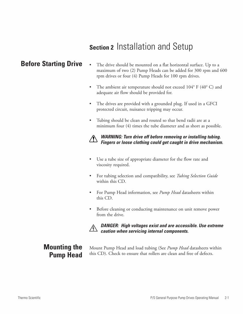
Section 2 Installation and Setup
• The drive should be mounted on a flat horizontal surface. Up to amaximum of two (2) Pump Heads can be added for 300 rpm and 600rpm drives or four (4) Pump Heads for 100 rpm drives.
• The ambient air temperature should not exceed 104° F (40° C) andadequate air flow should be provided for.
• The drives are provided with a grounded plug. If used in a GFCIprotected circuit, nuisance tripping may occur.
• Tubing should be clean and routed so that bend radii are at aminimum four (4) times the tube diameter and as short as possible.
WARNING: Turn drive off before removing or installing tubing.Fingers or loose clothing could get caught in drive mechanism.
• Use a tube size of appropriate diameter for the flow rate and viscosity required.
• For tubing selection and compatibility, see Tubing Selection Guidewithin this CD.
• For Pump Head information, see Pump Head datasheets within this CD.
• Before cleaning or conducting maintenance on unit remove powerfrom the drive.
DANGER: High voltages exist and are accessible. Use extremecaution when servicing internal components.
Mount Pump Head and load tubing (See Pump Head datasheets withinthis CD). Check to ensure that rollers are clean and free of defects.
Before Starting Drive
Mounting the Pump Head


P/S General Purpose Pump Drives Operating Manual 3-1Thermo Scientific
Inserting Tubing
Section 3 Operation
WARNINGS: Tubing breakage may result in fluid beingsprayed from pump. Use appropriate measures to protectoperator and equipment.
Turn Pump System off before removing or installing tubing.Fingers or loose clothing could be caught in the pump mechanism.
CAUTION: To avoid electrical shock, the power cord protec-tive grounding conductor must be connected to ground. Notfor operation in wet locations as defined by EN61010-1.
If the product is not used in a manner specified in theinstructions, the protection provided by the equipmentmay be impaired.
Tubing should be inspected periodically for tears, cracks, cut marks,abrasions, inability to hold pressure, bubbles in the flow stream andreduction or loss of flow.
Tubing life may be extended by periodically moving the worn tubinginside the occlusion bed of the pump to the outside of the occlusion bedto the suction side of the pump. This will avoid excessive tubing wear atany specific point.
Always move the worn tubing to the suction side of the pump.
CAUTION: When changing flow direction, allow the pumpto come to a complete stop before starting again. Failure todo so could cause permanent damage to the motor.
1. Make sure the speed is set to the minimum setting.
2. Turn the power switch ON. Increase the speed to start the pumpaction. The higher the rpm setting, the faster the speed of the pump.
3. The P/S General Purpose Drives are self-priming. To begin pumping,select a flow direction with the flow direction button, insert the intakeand output tubing into a reservoir, and turn the unit ON. Prime thetubing for at least 5 minutes. If accurate flow control is important,allow the pump to prime for approximately 20 minutes for more stableflow conditions.
Tubing Inspection andReplacement
Pump Controls

3-2 P/S General Purpose Pump Drives Operating Manual Thermo Scientific
Section 3Operation
External Operation Models are equipped with inputs that can be controlled by external signalsconnected at the rear panel 9-pin “D” shell connector. The external inputspermit control of the pump by remote equipment or accessories. Figure 3-1indicates the signal locations in the connector.
Pin No. Description1 Speed Control Voltage Input (0–10V) (+) input2 Speed Control Current Input (4–20 mA) (+) input3 Speed Control Input Reference Common4 Local/Remote Speed Control5 Local/Remote Speed Control Reference6 Start/Stop and CW/CCW Reference7 Start/Stop (+) Control8 CW/CCW9 Chassis (Earth) Ground
Figure 3-1. DB9 Pin Configuration with Wiring Scheme
Keypad LockoutEnable/Disable
Press and hold the INT/EXT key. After five (5) seconds, display will change to all dashes. Release INT/EXT key and press UP ARROW key (▲)five (5) times. Repeat this process to unlock the keypad. When the keypadis locked out, display will change to display all dashes (- - - - -) when a keyis depressed.
Note: Jumpers “A” and “B” areoptional. See page 3-3 ExternalInputs for correct usage.
P/S General Purpose Pump Drives Operating Manual 3-3Thermo Scientific
Section 3Operation
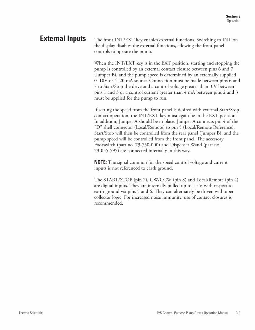
The front INT/EXT key enables external functions. Switching to INT onthe display disables the external functions, allowing the front panelcontrols to operate the pump.
When the INT/EXT key is in the EXT position, starting and stopping thepump is controlled by an external contact closure between pins 6 and 7(Jumper B), and the pump speed is determined by an externally supplied0–10V or 4–20 mA source. Connection must be made between pins 6 and7 to Start/Stop the drive and a control voltage greater than 0V betweenpins 1 and 3 or a control current greater than 4 mA between pins 2 and 3must be applied for the pump to run.
If setting the speed from the front panel is desired with external Start/Stopcontact operation, the INT/EXT key must again be in the EXT position.In addition, Jumper A should be in place. Jumper A connects pin 4 of the“D” shell connector (Local/Remote) to pin 5 (Local/Remote Reference).Start/Stop will then be controlled from the rear panel (Jumper B), and thepump speed will be controlled from the front panel. The accessoryFootswitch (part no. 73-750-000) and Dispenser Wand (part no. 73-055-595) are connected internally in this way.
NOTE: The signal common for the speed control voltage and currentinputs is not referenced to earth ground.
The START/STOP (pin 7), CW/CCW (pin 8) and Local/Remote (pin 4)are digital inputs. They are internally pulled up to +5 V with respect toearth ground via pins 5 and 6. They can alternately be driven with opencollector logic. For increased noise immunity, use of contact closures isrecommended.
External Inputs

P/S General Purpose Pump Drives Operating Manual 4-1Thermo Scientific
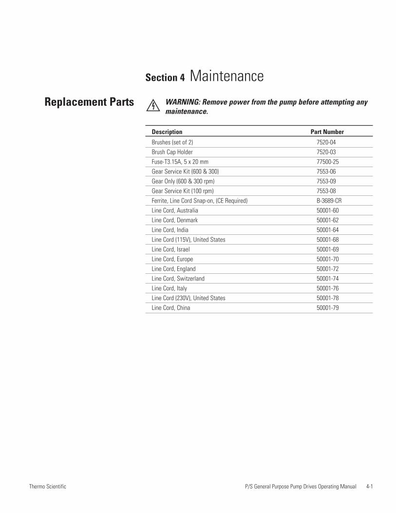
Section 4 Maintenance
Replacement Parts WARNING: Remove power from the pump before attempting anymaintenance.
Description Part Number
Brushes (set of 2) 7520-04Brush Cap Holder 7520-03Fuse-T3.15A, 5 x 20 mm 77500-25Gear Service Kit (600 & 300) 7553-06Gear Only (600 & 300 rpm) 7553-09Gear Service Kit (100 rpm) 7553-08Ferrite, Line Cord Snap-on, (CE Required) B-3689-CRLine Cord, Australia 50001-60Line Cord, Denmark 50001-62Line Cord, India 50001-64Line Cord (115V), United States 50001-68Line Cord, Israel 50001-69Line Cord, Europe 50001-70Line Cord, England 50001-72Line Cord, Switzerland 50001-74Line Cord, Italy 50001-76Line Cord (230V), United States 50001-78Line Cord, China 50001-79
4-2 P/S General Purpose Pump Drives Operating Manual Thermo Scientific
Section 4Section title
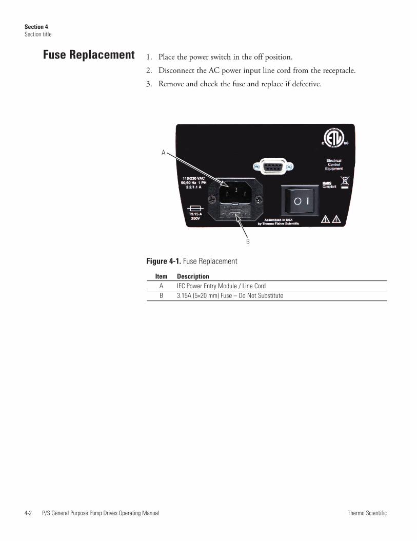
Fuse Replacement
Item DescriptionA IEC Power Entry Module / Line CordB 3.15A (5×20 mm) Fuse – Do Not Substitute
1. Place the power switch in the off position.
2. Disconnect the AC power input line cord from the receptacle.
3. Remove and check the fuse and replace if defective.
Figure 4-1. Fuse Replacement
A
B

P/S General Purpose Pump Drives Operating Manual 4-3Thermo Scientific
Section 4Section title
A
C
D
Motor Gear and BrushReplacement
Figure 4-2. Motor Gear and Brush Replacement
A. 6-600 & 3-300 rpm gear assembly (included in service kit 7553-06)B. GasketC. 1-100 rpm gear set (included in service kit 7553-08)D. Gear Case cover assemblyE. Brush Cap F. Motor Brush (set of two included in 7520-04)
B
Cleaning WARNING: Remove power from the pump before any cleaningoperation is started.
Keep the drive enclosure clean with mild detergents. Do not immerse oruse excessive fluid when cleaning.
F
E


P/S General Purpose Pump Drives Operating Manual 5-1Thermo Scientific
Section 5 Troubleshooting
Symptom Remedy
Unit will not turn on If the unit is plugged into a GFCI protected circuit verify that the circuit has not been tripped or reset the circuit.
Verify that the unit is plugged into a functioning outlet.
Verify that the power cord is firmly attached to the unit.
Verify that the fuse for the incoming voltage is not blown (located in the slot next to the power cord).
Check the tubing. Tubing should be snug, but not tight, against the rollers.
Verify that the mode EXT/INT is set correctly.
Error XX is displayed on the screen Err's 3 & 10, check pump for obstructions, all other Errs return unit for repair.
Unit will turn on but display would Verify that the incoming voltage meets the required dim and pump will not spin minimum of 90Vrms.
Unit vibrates excessively when Check that the tubing was loaded properly.pump is running
Troubleshooting Chart
Unit will turn on but pump will not spin


P/S General Purpose Pump Drives Operating Manual 6-1Thermo Scientific
Section 6 Accessories
1. Footswitch 73-750-000
2. Dispenser Wand 73-055-595
3. DB-9 External Control Connector 7595-45
4. DB-9 Remote control cable, 25 FT. 980-7597
5. Tilt Bail 7523-98
Accessories


Section 7 Specifications
Output:Speed:1400-1120 1 - 100 rpm1400-1320 3 - 300 rpm1400-1620 6 - 600 rpm
Torque, Maximum:300 & 600 rpm models 180 oz-in (13 kg•cm), 540 oz-in Starting100 rpm models 360 oz-in (26 kg•cm), 1080 oz-in Starting
Input:Operating Voltage/Frequency: 90-260Vrms, 50/60 Hz, 2.2A @ 115Vrms,
1.1A @ 230 VrmsExternal Inputs:START/STOP, CW/CCW, Contact closureRemote/Local Speed ControlVoltage input 0–10V DC @ 10 kohm, Accuracy: ±0.5% Full ScaleCurrent input 4–20 mA @ 250 ohm,Accuracy: ±0.5% Full Scale
Environment:Operating Temperature: 32 to 104°F (0 to 40°C) Storage Temperature: -13 to 149°F (-25 to 65°C) Humidity: 10% to 90% non-condensing Altitude: Less than 6562 ft (2000 m)Pollution Degree: Pollution degree 2 (indoor use–lab, office)
Construction:Dimensions (L × W × H): 10.5 in × 8 in × 8 in
(267 × 203 × 203 mm)Weight: 6.9 kgs (15.2lbs)Color: Light Grey (5% Black)Material: Aluminum, ABS plastic and vinylEnclosure Rating: IP33 per IEC-60529
P/S General Purpose Pump Drives Operating Manual 7-1Thermo Scientific

Compliance: UL 61010-1, CAN/CSA-C22.2 No. 61010-1This product has been tested to the requirements of CAN/CSA-C22.2 No. 61010-1, second edition, including Amendment 1, or a later version of the same standard incorporating the same level of testing requirements.(For CE Mark):EN61010-1: (EU Low Voltage Directive) andEN61326: (EU EMC Directive)
7-2 P/S General Purpose Pump Drives Operating Manual Thermo Scientific
Section 7Specifications

Section 8 Warranty, Product Return andTechnical Assistance
This product is warranted against defects in material or workmanship, andat the option of the manufacturer or distributor, any defective product willbe repaired or replaced at no charge, or the purchase price will be refundedto the purchaser, provided that: (a) the warranty claim is made in writingwithin the period of time specified on the warranty card, (b) proof ofpurchase by bill of sale or receipted invoice is submitted concurrently withthe claim and shows that the product is within the applicable warrantyperiod, and (c) the purchaser complies with procedures for returns setforth in the general terms and conditions contained in the manufacturer'sor distributor's most recent catalog.
This warranty shall not apply to: (a) defects or damage resulting from: (i)misuse of the product, (ii) use of the product in other than its normal andcustomary manner, (iii) accident or neglect, (iv) improper testing,operation, maintenance, service, repair, installation, or storage, (v)unauthorized alteration or modification, or (b) post-expiration datedmaterials.
THIS WARRANTY IS THE EXCLUSIVE REMEDY OF THEPURCHASER, AND THE MANUFACTURER AND DISTRIBUTORDISCLAIM ALL OTHER WARRANTIES, WHETHER EXPRESS,IMPLIED, OR STATUTORY, INCLUDING WITHOUTLIMITATION, WARRANTIES OF MERCHANTABILITY ANDFITNESS FOR A PARTICULAR PURPOSE. NO EMPLOYEE,AGENT, OR REPRESENTATIVE OF THE MANUFACTURER ORDISTRIBUTOR IS AUTHORIZED TO BIND THEMANUFACTURER OR DISTRIBUTOR TO ANY OTHERWARRANTY. IN NO EVENT SHALL THE MANUFACTURER ORDISTRIBUTOR BE LIABLE FOR INCIDENTAL, INDIRECT,SPECIAL OR CONSEQUENTIAL DAMAGES.
The warranty period for this product is two (2) years from date of purchase.
P/S General Purpose Pump Drives Operating Manual 8-1Thermo Scientific
Warranty

8-2 P/S General Purpose Pump Drives Operating Manual Thermo Scientific
Section 8Warranty, Product Return and Technical Assistance
To limit charges and delays, contact the seller or Manufacturer forauthorization and shipping instructions before returning the product, eitherwithin or outside of the warranty period. When returning the product, pleasestate the reason for the return. For your protection, pack the productcarefully and insure it against possible damage or loss. Any damages resultingfrom improper packaging are your responsibility.
If you have any questions about the use of this product, contact theManufacturer or authorized seller.
Product Return
Technical Assistance


Thermo Fisher Scientific28W092 Commercial Ave.Barrington, Illinois U.S.A. 60010-23921-800-637-3739 (U.S. and Canada only)11 (847) 381-7050 (Outside U.S.)(847) 381-7050 (Local)
www.thermoscientific.com [email protected]
33
CC1