proximity probe checker pc-100 - amc vibro€¦ · status of the proximity probe position on a led...
TRANSCRIPT

Proximity
Probe Checker
PC-100
User Manual
September 2015, Rev. 5.3
NORTH Protection Ltd, Member of the NORTH Group Page 2 of 14
Please read carefully this manual before
Operating the Proximity Probe Checker
PC-100

NORTH Protection Ltd, Member of the NORTH Group Page 3 of 14
Contents
1 Product Description .................................................................................. 4
2 Basis Data of PC-100 Proximity Probe Checker .................................... 5
3 Using PC-100 Proximity Probe Checker ................................................ 6
3.1 GAP TEST Mode ............................................................................. 7
3.2 CURRENT SOURCE Mode ........................................................... 9
4 Application Notes .................................................................................... 10
5 Battery Replacement ............................................................................... 12
6 Device Dimension .................................................................................... 13
N o t i c e s .......................................................................................................... 14
NORTH Protection Ltd, Member of the NORTH Group Page 4 of 14
1 Product Description
PC-100 is a battery operated, easy to use instrument for checking proximity probe GAP
voltage, which is then indicated on LED bar integrated on the front panel. There is also an LCD
screen for displaying GAP voltage for better accuracy. PC-100 can also be used to simulate a Two-
Wire Loop Powered Transmitter with a DC constant current output of 12.0 mA.
PC-100 is powered by one 9V Alkaline Battery (6LR61). LED indication of LOW Battery is also
present. Operating modes can be selected using the slide switch mounted on the left side of
instrument.
There is also a visual identification of the selected mode, placed on the front panel. In the middle
position of the switch, the device is off.
In GAP TEST Mode, PC-100 measures a proximity probe GAP voltage at the buffered output of the
Proximitor. The measured voltage is displayed on an LCD screen and on LEDs, indicating a distance
of proximity sensor in relation with the object. Using this device with LED bar indicator enables easy
adjustment of a proximity probe gap.
In CURRENT SOURCE Mode, this device operates as a Two-Wire Loop Powered Transmitter and
produces a fixed DC output current of 12.0 mA.
Specifications
Connectors
GAP Input Proximity probe input (±1 ... ±24V DC buffered output from Proximitor)
CURRENT Output Two-wires loop powered constant current output
Output
Constant current 12.0 mA, DC
Accuracy ± 0.5%
Environmental Features
Temperature:
Operating -10°C to +65°C
Storage -18°C to +65°C
Humidity 95% R.H. maximum
Power
Battery 1 x 9V Alkaline Battery (6LR61)
Autonomy
GAP TEST Mode >8h
CURRENT Mode >20h
Physical Features
Dimension 150mm x 80mm x 30mm
Weight 0.4kg typical of Kit
Case Molded Plastic Case
Connection BNC Connectors
NORTH Protection Ltd, Member of the NORTH Group Page 5 of 14
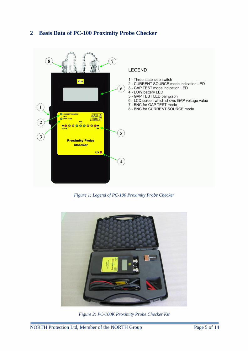
2 Basis Data of PC-100 Proximity Probe Checker
Figure 1: Legend of PC-100 Proximity Probe Checker
Figure 2: PC-100K Proximity Probe Checker Kit
NORTH Protection Ltd, Member of the NORTH Group Page 6 of 14
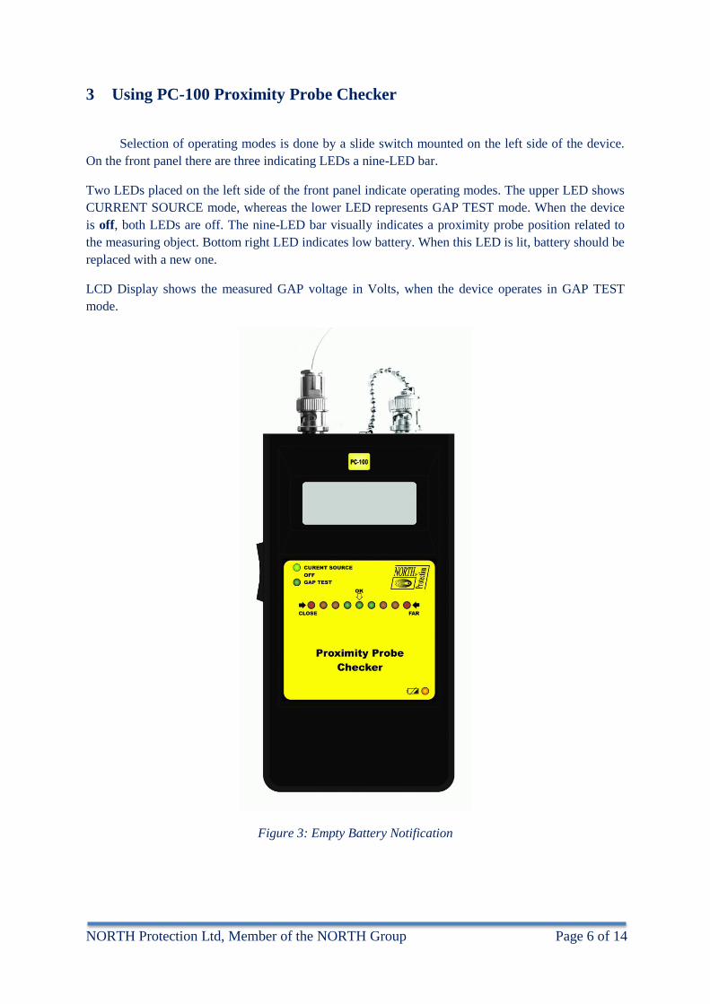
3 Using PC-100 Proximity Probe Checker
Selection of operating modes is done by a slide switch mounted on the left side of the device.
On the front panel there are three indicating LEDs a nine-LED bar.
Two LEDs placed on the left side of the front panel indicate operating modes. The upper LED shows
CURRENT SOURCE mode, whereas the lower LED represents GAP TEST mode. When the device
is off, both LEDs are off. The nine-LED bar visually indicates a proximity probe position related to
the measuring object. Bottom right LED indicates low battery. When this LED is lit, battery should be
replaced with a new one.
LCD Display shows the measured GAP voltage in Volts, when the device operates in GAP TEST
mode.
Figure 3: Empty Battery Notification
NORTH Protection Ltd, Member of the NORTH Group Page 7 of 14
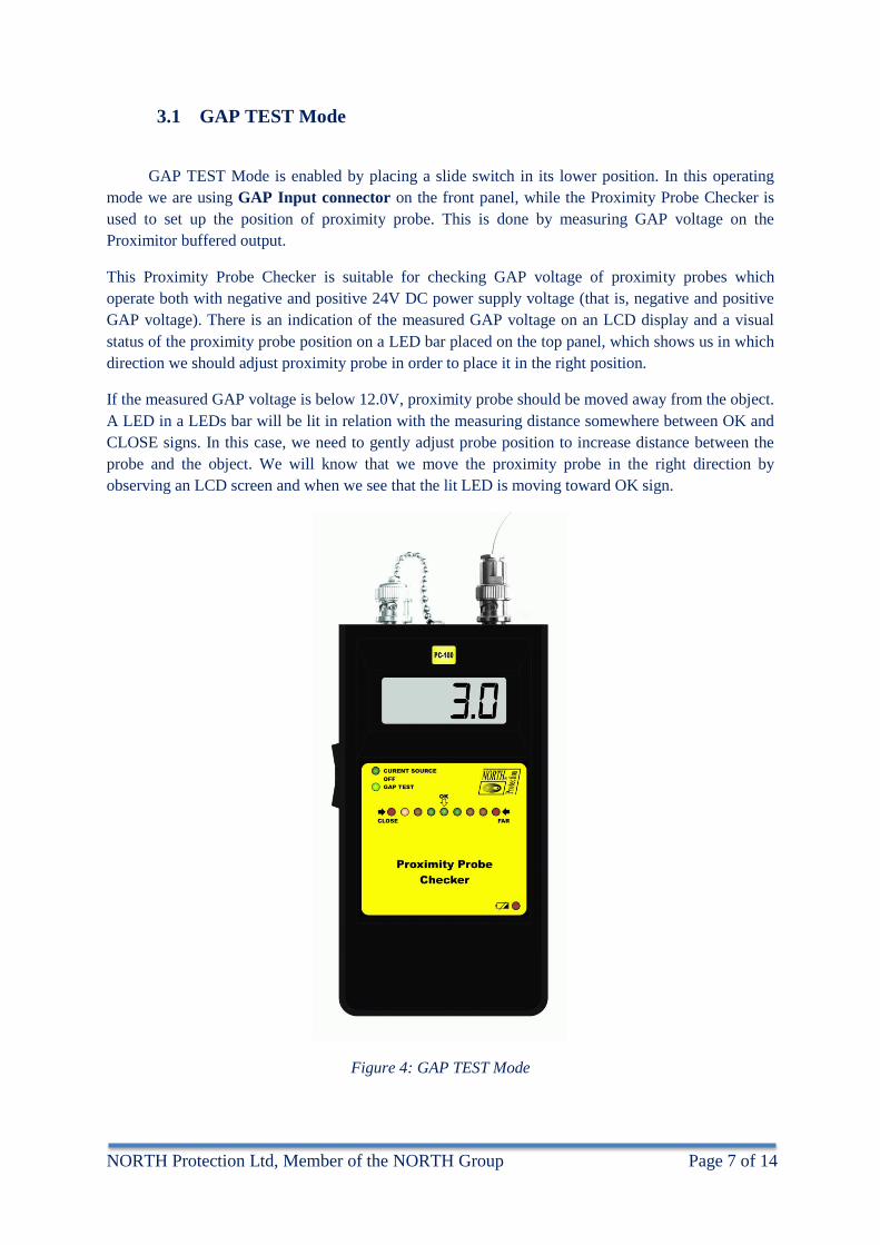
3.1 GAP TEST Mode
GAP TEST Mode is enabled by placing a slide switch in its lower position. In this operating
mode we are using GAP Input connector on the front panel, while the Proximity Probe Checker is
used to set up the position of proximity probe. This is done by measuring GAP voltage on the
Proximitor buffered output.
This Proximity Probe Checker is suitable for checking GAP voltage of proximity probes which
operate both with negative and positive 24V DC power supply voltage (that is, negative and positive
GAP voltage). There is an indication of the measured GAP voltage on an LCD display and a visual
status of the proximity probe position on a LED bar placed on the top panel, which shows us in which
direction we should adjust proximity probe in order to place it in the right position.
If the measured GAP voltage is below 12.0V, proximity probe should be moved away from the object.
A LED in a LEDs bar will be lit in relation with the measuring distance somewhere between OK and
CLOSE signs. In this case, we need to gently adjust probe position to increase distance between the
probe and the object. We will know that we move the proximity probe in the right direction by
observing an LCD screen and when we see that the lit LED is moving toward OK sign.
Figure 4: GAP TEST Mode

NORTH Protection Ltd, Member of the NORTH Group Page 8 of 14
Our primary the aim is to set the proximity probe in the middle position of its linear range. When the
proximity probe is set in the right position, OK LED will be lit, and an LCD display will show 12.0 V
DC.
If the measured voltage is above 12.0 V, the proximity probe should be adjusted closer to the object.
LEDs bar will light up in relation with the distance somewhere between OK and FAR signs. In this
case, we need to gently adjust the probe position to decrease distance between probe and object. We
will know that we move the probe in the proper direction by observig LCD screen and when we see
that the lit up LED is moving toward OK sign.
a) b)
Figure 5: GAP TEST Mode – LED Signalization
a) Proximity probe in good position; b) Proximity probe too far from the measured object

NORTH Protection Ltd, Member of the NORTH Group Page 9 of 14
3.2 CURRENT SOURCE Mode
CURRENT SOURCE Mode is selected by placing a slide switch in the upper position. In this
operating mode we are using Current output (mA Out) connector on the front panel. Now, on this
output the Proximity Probe Checker produces 12.0 mA DC constant current and acts as a Two-Wire
Loop Powered Transmitter. This value for current is factory adjusted and it is chosen based on 50% of
the measuring range for 4...20mA Loop Powered Transmitters (60% of measuring range for
0...20mA). In this operating mode, LCD display is Off, and only the LED indicating this operating
mode is lit on top panel. Application note for this operating mode is given in Chapter 4.
Figure 6: CURRENT SOURCE Mode

NORTH Protection Ltd, Member of the NORTH Group Page 10 of 14
4 Application Notes
When we are using PC-100 as a GAP test device, we need to connect it to a buffered output of
the Proximity Probe Transmiter (Proximitor), as it is shown in Figure 7. PC-100 will measure only
DC GAP voltage, so we can use this Proximity Probe Checker to check and adjust the proximity
probe position while the measured object is rotating.
Figure 7: GAP TEST Mode
NORTH Protection Ltd, Member of the NORTH Group Page 11 of 14
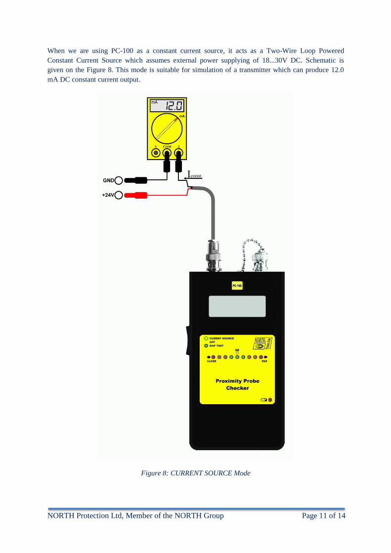
When we are using PC-100 as a constant current source, it acts as a Two-Wire Loop Powered
Constant Current Source which assumes external power supplying of 18...30V DC. Schematic is
given on the Figure 8. This mode is suitable for simulation of a transmitter which can produce 12.0
mA DC constant current output.
Figure 8: CURRENT SOURCE Mode
NORTH Protection Ltd, Member of the NORTH Group Page 12 of 14
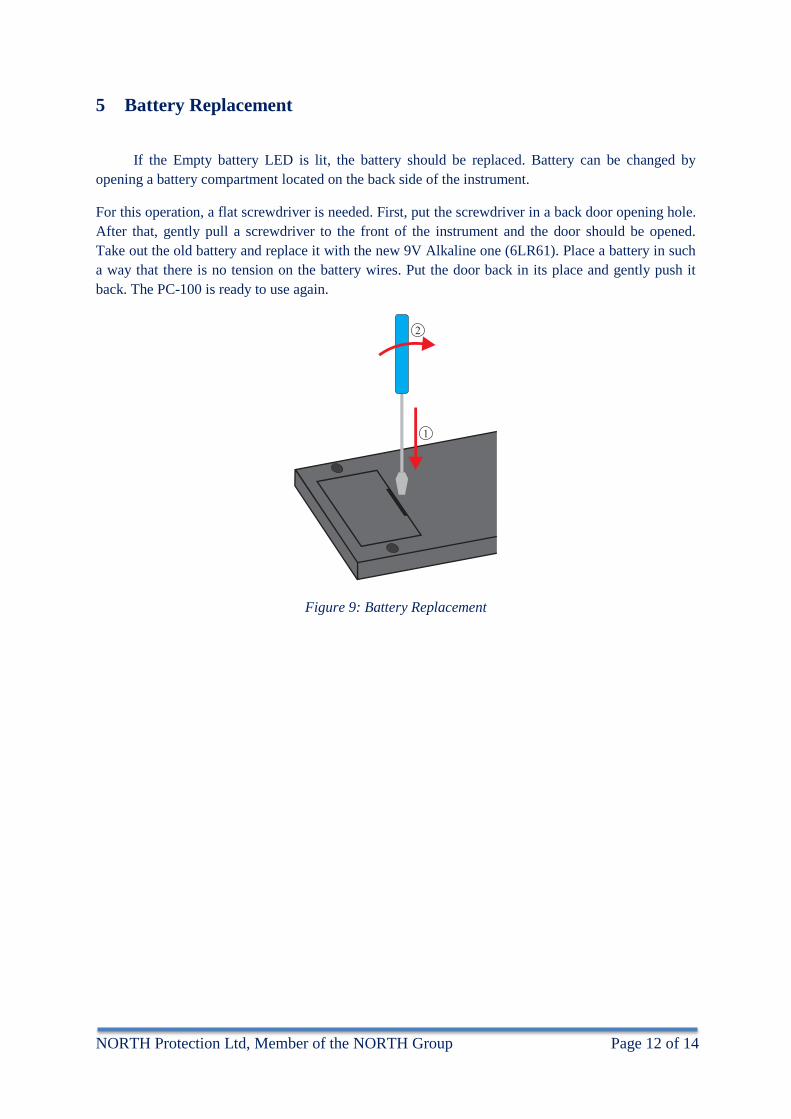
5 Battery Replacement
If the Empty battery LED is lit, the battery should be replaced. Battery can be changed by
opening a battery compartment located on the back side of the instrument.
For this operation, a flat screwdriver is needed. First, put the screwdriver in a back door opening hole.
After that, gently pull a screwdriver to the front of the instrument and the door should be opened.
Take out the old battery and replace it with the new 9V Alkaline one (6LR61). Place a battery in such
a way that there is no tension on the battery wires. Put the door back in its place and gently push it
back. The PC-100 is ready to use again.
Figure 9: Battery Replacement
NORTH Protection Ltd, Member of the NORTH Group Page 13 of 14
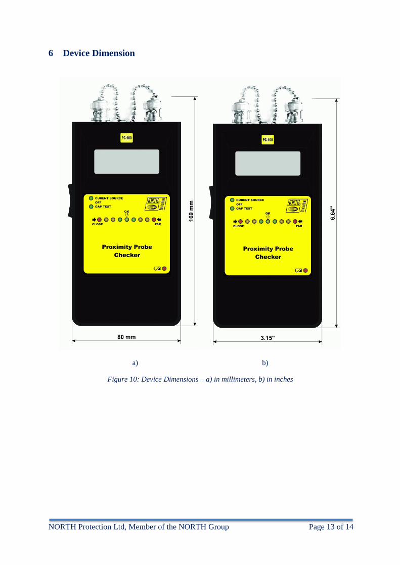
6 Device Dimension
a) b)
Figure 10: Device Dimensions – a) in millimeters, b) in inches

NORTH Protection Ltd, Member of the NORTH Group Page 14 of 14
N o t i c e s