proximity operations and docking sensor development · 17.12.2008 · proximity operations and...
TRANSCRIPT

Proximity Operations and Docking Sensor DevelopmentRichard T. Howard, Thomas C. Bryan and Linda L. Brewster
Automated Rendezvous and Docking Development and Test Branch (ES62)NASA, Marshall Space Flight Center, Huntsville, Alabama, 35812
256-544-3536 [email protected] [email protected]
256-544-0169 [email protected]
James E. LeeExplorations Advanced Capabilities Office (VP33)
NASA, Marshall Space Flight Center, Huntsville, Alabama, 35812256-544-4951 [email protected]
Abstract—The Next Generation Advanced VideoGuidance Sensor (NGAVGS) has been underdevelopment for the last three years as a long-rangeproximity operations and docking sensor for use in anAutomated Rendezvous and Docking (AR&D) system.The first autonomous rendezvous and docking in thehistory of the U.S. Space Program was successfullyaccomplished by Orbital Express, using the AdvancedVideo Guidance Sensor (AVGS) as the primary dockingsensor. That flight proved that the United States now hasa mature and flight proven sensor technology forsupporting Crew Exploration Vehicles (CEV) andCommercial Orbital Transport Systems (COTS)Automated Rendezvous and Docking (AR&D). NASAvideo sensors have worked well in the past: the AVGSused on the Demonstration of Autonomous RendezvousTechnology (DART) mission operated successfully in“spot mode” out to 2 km, and the first generationrendezvous and docking sensor, the Video GuidanceSensor (VGS), was developed and successfully flown onSpace Shuttle flights in 1997 and 1998. 12
Parts obsolescence issues prevent the construction ofmore AVGS units, and the next generation sensor wasupdated to allow it to support the CEV and COTSprograms. The flight proven AR&D sensor has beenredesigned to update parts and add additional capabilitiesfor CEV and COTS with the development of the NextGeneration AVGS at the Marshall Space Flight Center.The obsolete imager and processor are being replacedwith new radiation tolerant parts. In addition, newcapabilities include greater sensor range, auto rangingcapability, and real-time video output.
This paper presents some sensor hardware trades, use ofhighly integrated laser components, and addresses theneeds of future vehicles that may rendezvous and dockwith the International Space Station (ISS) and otherConstellation vehicles. It also discusses approaches forupgrading AVGS to address parts obsolescence, andconcepts for minimizing the sensor footprint, weight, and
11 U.S. Government work not protected by U.S. copyright2 IEEEAC paper #1287, Version 1, Updated December 17, 2008
power requirements. In addition, the testing of thebrassboard and proto-type NGAVGS units will bediscussed along with the use of the NGAVGS as aproximity operations and docking sensor.
TABLE OF CONTENTS
1. INTRODUCTION .................................................................12. FLIGHT HISTORY ............................................................. 23. SENSOR SPECIFICATIONS .................................................34. SENSOR DEVELOPMENT ...................................................45. NGAVGS TESTING ..........................................................56. CONCLUSIONS .................................................................. 7REFERENCES ........................................................................ 8BIOGRAPHIES ....................................................................... 8
1. INTRODUCTION
The NGAVGS is a National Aeronautics and SpaceAdministration (NASA) Marshall Space Flight Center(MSFC) developed sensor capable of supportingautomated operations for spacecraft rendezvous,spacecraft proximity operations, spacecraft docking,spacecraft free-flyer capture, fluid transfers, and OrbitalReplacement Unit (ORU) transfers. The NGAVGSbuilds on the technology of the AVGS, incorporatingrequirements to support the longer ranges required by theCrew Exploration Vehicle (CEV or Orion), up to 5000meters, and real-time video output. Since one of the keytechnologies required to support the International SpaceStation (ISS) re-supply as well as the NASAConstellation Program is Automated Rendezvous andDocking (AR&D), AR&D sensor robustness is vital.Thus, radiation is a bigger concern for the current sensorthan it was for the Orbital Express (OE) Mission.
As an in-house project, the technologies and testingrequired for VGS, AVGS and now NGAVGS weredeveloped by engineers within the MSFC EngineeringDirectorate, continuing the long AR&D heritage atMSFC. These engineers hold a combined 11 patents onthese sensors and related technologies. The NGAVGSflight hardware and software design is also beingaccomplished by the MSFC Engineering Directorate
https://ntrs.nasa.gov/search.jsp?R=20090025872 2019-07-07T16:01:46+00:00Z

personnel. An internal study was conducted in late 2006to assess 13 different configuration options for theNGAVGS. The Processor Control Board (PCB) and theimager were key components assessed as a part of thistrade study. The recommendation resulting from thistrade was a two box configuration with a remote camerahead and laser/electronics box that could be internallymounted in the spacecraft to provide radiation protectionand thermal dissipation. In addition, a one-box optionwas also designed to provide an easier to integrate sensorsolution. Two different NGAVGS brassboards were builtbased on the two-box configuration, and two prototypeswere built based on the one-box configuration. Thebrassboard 2/3 is depicted below in Figure 1.
The first sensor built to fly was the Video GuidanceSensor (VGS). It was based on a modified video camera,frame grabber, processor, and software. The VGS wasdesigned as the sensor that would be used to guide aspacecraft the last 100 meters of its AR&D mission (withthe earlier portion of the mission guided by inertialnavigation sensors and GPS.) The VGS was flown on theShuttle on STS-87 and STS-95. It tracked a target thatwas mounted on a SPARTAN free-flyer. During STS-87,there were some problems with the SPARTAN release, sothe VGS only got to track the SPARTAN while it was onthe shuttle Remote Manipulator System (RMS). Thatlimited the range to a maximum of about 13 meters. OnSTS-95, the full mission was carried out, and the VGSgot to track the SPARTAN intermittently at 200 metersand constantly from 150 meters in to 10 meters (theminimum approach range). In addition, more data wastaken with the SPARTAN mounted on the RMS. [1] [2]
Figure 2: AVGS flight unit mounted on the front ofthe DART vehicle
Figure 1: NGAVGS Brassboard 2/3 configuration
2. FLIGHT HISTORY
The NGAVGS is the latest sensor in a long line of videosensors developed for automated rendezvous anddocking. The proto-type sensors were developed andtested in the MSFC Flight Robotics Laboratory and wereinitially used to guide a 3-degree-of-freedom (3-DOF)vehicle from an initial position 10 to 20 meters away fromthe sensor all the way into contact with the target locationand throughout the closure of a docking mechanism.
The next generation of sensor was initially developed in-house, and then the flight version of the hardware wasbuilt by Orbital Sciences Corporation. The software wasall written, verified, and validated by MSFC’s FlightSoftware group. The Advanced Video Guidance Sensor(AVGS) shown in Figure 2 was 5 times faster than theVGS, used about 1/3 the power, and weighed less thanhalf what the VGS weighed. It was the proximityoperations sensor mounted on the front of theDemonstration of Autonomous Rendezvous Technologies(DART) vehicle. The AVGS was capable of acquiringand tracking a target from 300 meters in to docking range(but 4 meters was the closest planned approach range forDART.) While tracking a target, the AVGS provided allsix pieces of relative position and attitude information. Inaddition, the AVGS had a Spot mode in which it wouldsimply provide bearing information to any spots that itsaw. This mode worked at ranges up to 2 kilometers
2
during the DART mission, but unfortunately the sensorwas never commanded into its tracking mode. [3] [4]
An upgraded version of the DART AVGS was desired byBoeing to be used on the Orbital Express (OE) mission.The changes to the sensor were minor, involving tighterthermal controls on some of the optical components and anew mounting location. The software underwentsignificant improvements, some due to lessons learned onthe DART AVGS and some due to new requirements.The DART mission was only supposed to last 24 hours,so there was no need to update the software on orbit. TheOE mission was originally scheduled to be on orbit for upto one year, so the software needed to have the ability tobe updated. In addition, there were a number ofparameters that may have needed adjusting, so an I-Load(Initial-Load) capability was created so some parameterscould be quickly and easily changed without recompiling,validating, and loading a complete set of new software.The OE mission was extremely successful, with theAVGS being used from docking range (about 1 meter) allthe way out to 150 meters (despite the fact that theplanned use of AVGS was never to have been beyond120 meters.) [5] [6] [7] [8]
3. SENSOR SPECIFICATIONS
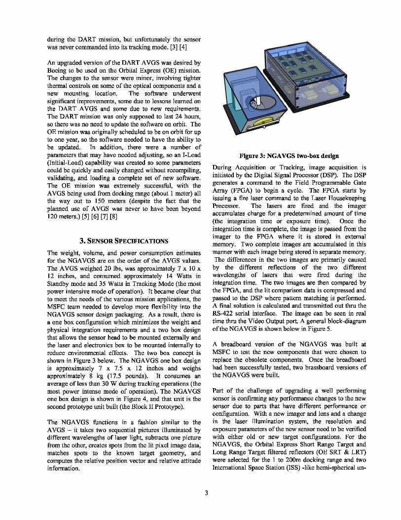
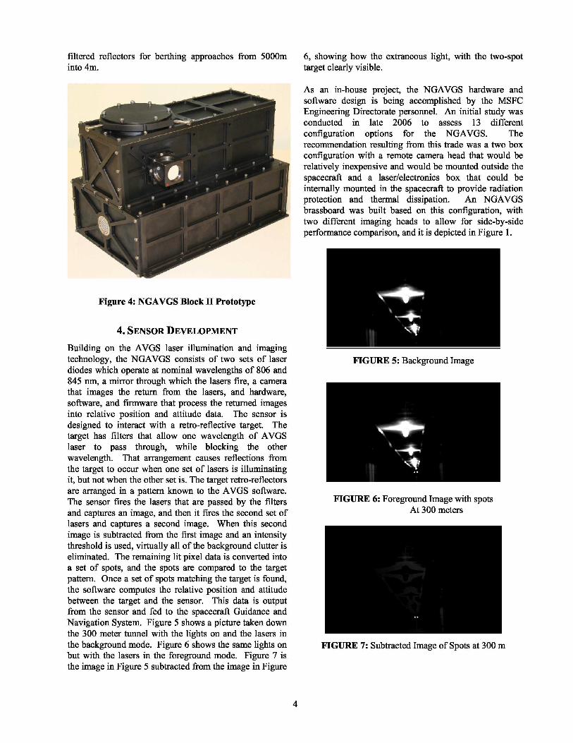
The weight, volume, and power consumption estimatesfor the NGAVGS are on the order of the AVGS values.The AVGS weighed 20 lbs, was approximately 7 x 10 x12 inches, and consumed approximately 14 Watts inStandby mode and 35 Watts in Tracking Mode (the mostpower intensive mode of operation). It became clear thatto meet the needs of the various mission applications, theMSFC team needed to develop more flexibility into theNGAVGS sensor design packaging. As a result, there isa one box configuration which minimizes the weight andphysical integration requirements and a two box designthat allows the sensor head to be mounted externally andthe laser and electronics box to be mounted internally toreduce environmental effects. The two box concept isshown in Figure 3 below. The NGAVGS one box designis approximately 7 x 7.5 x 12 inches and weighsapproximately 8 kg (17.5 pounds). It consumes anaverage of less than 30 W during tracking operations (themost power intense mode of operation). The NGAVGSone box design is shown in Figure 4, and that unit is thesecond prototype unit built (the Block II Prototype).
The NGAVGS functions in a fashion similar to theAVGS – it takes two sequential pictures illuminated bydifferent wavelengths of laser light, subtracts one picturefrom the other, creates spots from the lit pixel image data,matches spots to the known target geometry, andcomputes the relative position vector and relative attitudeinformation.
Figure 3: NGAVGS two-box design
During Acquisition or Tracking, image acquisition isinitiated by the Digital Signal Processor (DSP). The DSPgenerates a command to the Field Programmable GateArray (FPGA) to begin a cycle. The FPGA starts byissuing a fire laser command to the Laser HousekeepingProcessor. The lasers are fired and the imageraccumulates charge for a predetermined amount of time(the integration time or exposure time). Once theintegration time is complete, the image is passed from theimager to the FPGA where it is stored in externalmemory. Two complete images are accumulated in thismanner with each image being stored in separate memory.The differences in the two images are primarily caused
by the different reflections of the two differentwavelengths of lasers that were fired during theintegration time. The two images are then compared bythe FPGA, and the lit comparison data is compressed andpassed to the DSP where pattern matching is performed.A final solution is calculated and transmitted out thru theRS-422 serial interface. The image can be seen in realtime thru the Video Output port. A general block-diagramof the NGAVGS is shown below in Figure 5.
A breadboard version of the NGAVGS was built atMSFC to test the new components that were chosen toreplace the obsolete components. Once the breadboardhad been successfully tested, two brassboard versions ofthe NGAVGS were built.
Part of the challenge of upgrading a well performingsensor is confirming any performance changes to the newsensor due to parts that have different performance orconfiguration. With a new imager and lens and a changein the laser illumination system, the resolution andexposure parameters of the new sensor need to be verifiedwith either old or new target configurations. For theNGAVGS, the Orbital Express Short Range Target andLong Range Target filtered reflectors (OE SRT & LRT)were selected for the 1 to 200m docking range and twoInternational Space Station (ISS) -like hemi-spherical un-
filtered reflectors for berthing approaches from 5000minto 4m.
6, showing how the extraneous light, with the two-spottarget clearly visible.
Figure 4: NGAVGS Block II Prototype
4. SENSOR DEVELOPMENT
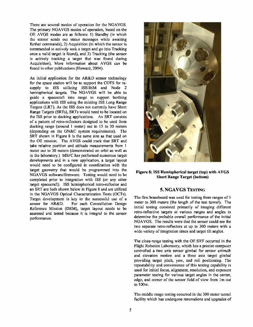
Building on the AVGS laser illumination and imagingtechnology, the NGAVGS consists of two sets of laserdiodes which operate at nominal wavelengths of 806 and845 nm, a mirror through which the lasers fire, a camerathat images the return from the lasers, and hardware,software, and firmware that process the returned imagesinto relative position and attitude data. The sensor isdesigned to interact with a retro-reflective target. Thetarget has filters that allow one wavelength of AVGSlaser to pass through, while blocking the otherwavelength. That arrangement causes reflections fromthe target to occur when one set of lasers is illuminatingit, but not when the other set is. The target retro-reflectorsare arranged in a pattern known to the AVGS software.The sensor fires the lasers that are passed by the filtersand captures an image, and then it fires the second set oflasers and captures a second image. When this secondimage is subtracted from the first image and an intensitythreshold is used, virtually all of the background clutter iseliminated. The remaining lit pixel data is converted intoa set of spots, and the spots are compared to the targetpattern. Once a set of spots matching the target is found,the software computes the relative position and attitudebetween the target and the sensor. This data is outputfrom the sensor and fed to the spacecraft Guidance andNavigation System. Figure 5 shows a picture taken downthe 300 meter tunnel with the lights on and the lasers inthe background mode. Figure 6 shows the same lights onbut with the lasers in the foreground mode. Figure 7 isthe image in Figure 5 subtracted from the image in Figure
As an in-house project, the NGAVGS hardware andsoftware design is being accomplished by the MSFCEngineering Directorate personnel. An initial study wasconducted in late 2006 to assess 13 differentconfiguration options for the NGAVGS. Therecommendation resulting from this trade was a two boxconfiguration with a remote camera head that would berelatively inexpensive and would be mounted outside thespacecraft and a laser/electronics box that could beinternally mounted in the spacecraft to provide radiationprotection and thermal dissipation. An NGAVGSbrassboard was built based on this configuration, withtwo different imaging heads to allow for side-by-sideperformance comparison, and it is depicted in Figure 1.
FIGURE 5: Background Image
FIGURE 6: Foreground Image with spotsAt 300 meters
FIGURE 7: Subtracted Image of Spots at 300 m
4
There are several modes of operation for the NGAVGS.The primary NGAVGS modes of operation, based on theOE AVGS modes are as follows: 1) Standby (in whichthe sensor sends out status messages while awaitingfurther commands), 2) Acquisition (in which the sensor iscommanded to actively seek a target and go into Trackingonce a valid target is found), and 3) Tracking (the sensoris actively tracking a target that was found duringAcquisition). More information about AVGS can befound in other publications (Howard, 2004).
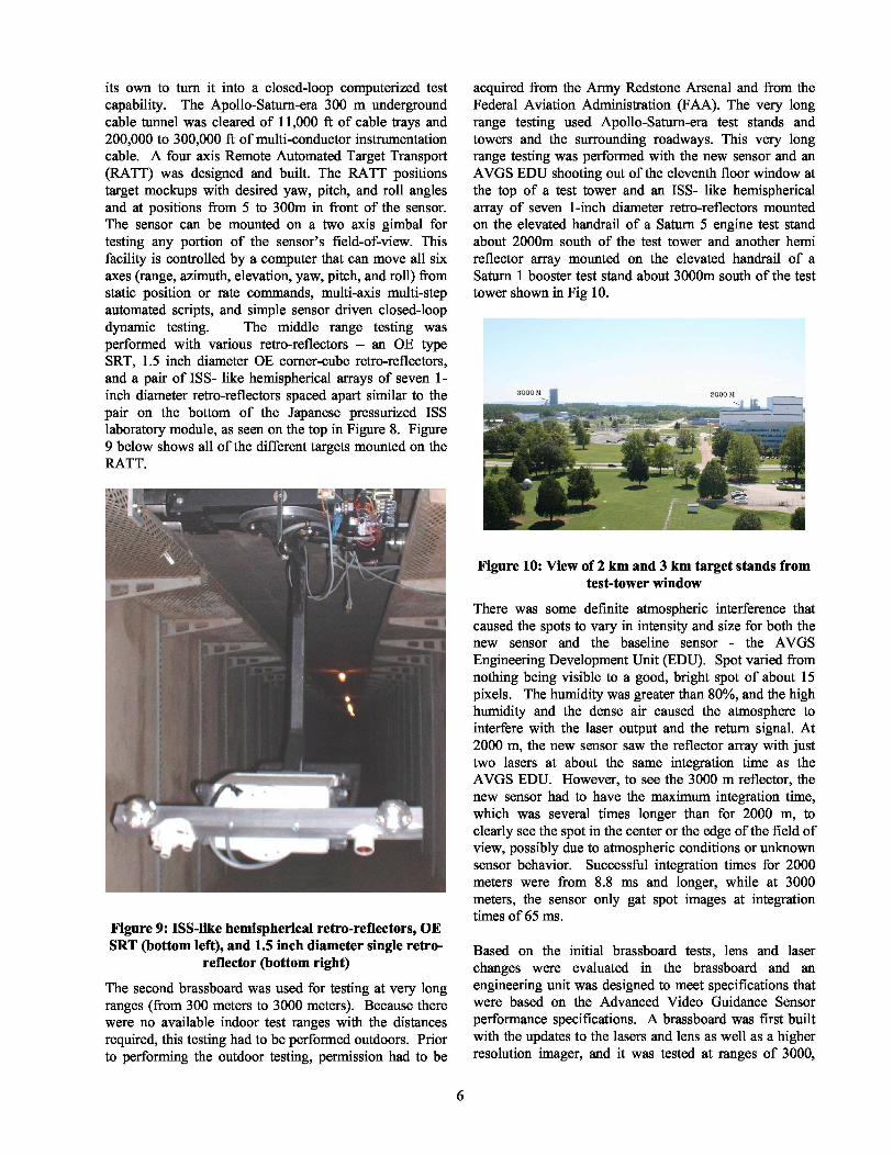
An initial application for the AR&D sensor technologyfor the space station will be to support the COTS for re-supply to ISS utilizing ISS/JEM and Node 2hemispherical targets. The NGAVGS will be able toguide a spacecraft into range to support berthingapplications with ISS using the existing ISS Long RangeTargets (LRT). As the ISS does not currently have ShortRange Targets (SRTs), SRTs would need to be located onthe ISS prior to docking applications. An SRT consistsof a pattern of retro-reflectors designed to be used fromdocking range (around 1 meter) out to 15 to 30 meters(depending on the GN&C system requirements). TheSRT shown in Figure 8 is the same size as that used onthe OE mission. The AVGS could track that SRT andtake relative position and attitude measurements from 1meter out to 30 meters (demonstrated on orbit as well asin the laboratory.) MSFC has performed numerous targetdevelopments and in a new application, a target layoutwould need to be configured in coordination with thetarget geometry that would be programmed into theNGAVGS software/firmware. Testing would need to becompleted prior to integration with ISS (or any othertarget spacecraft). ISS hemispherical retro-reflector andan SRT are both shown below in Figure 8 and are utilizedin the NGAVGS Optical Characterization Tests (OCTs).Target development is key to the successful use of asensor for AR&D. For each Constellation DesignReference Mission (DRM), target layout needs to beassessed and tested because it is integral to the sensorperformance.
Figure 8: ISS Hemispherical target (top) with AVGSShort Range Target (bottom)
5. NGAVGS TESTING
The first brassboard was used for testing from ranges of 1meter to 300 meters (the length of the test tunnel). Theinitial testing consisted primarily of imaging differentretro-reflective targets at various ranges and angles todetermine the probable overall performance of the initialNGAVGS. The results were that the sensor could see thetwo separate retro-reflectors at up to 300 meters with awide variety of integration times and target tilt angles.
The close-range testing with the OE SRT occurred in theFlight Robotics Laboratory, which has a precise computercontrolled a two axis sensor gimbal for sensor azimuthand elevation motion and a three axis target gimbalproviding target pitch, yaw, and roll positioning. Therepeatability and convenience of this testing capability isused for initial focus, alignment, resolution, and exposureparameter testing for various target angles in the center,edge, and corner of the sensor field of view from 1m outto 100m.
The middle range testing occurred in the 300 meter tunnelfacility which has undergone renovations and upgrades of
its own to turn it into a closed-loop computerized testcapability. The Apollo-Saturn-era 300 m undergroundcable tunnel was cleared of 11,000 ft of cable trays and200,000 to 300,000 ft of multi-conductor instrumentationcable. A four axis Remote Automated Target Transport(RATT) was designed and built. The RATT positionstarget mockups with desired yaw, pitch, and roll anglesand at positions from 5 to 300m in front of the sensor.The sensor can be mounted on a two axis gimbal fortesting any portion of the sensor’s field-of-view. Thisfacility is controlled by a computer that can move all sixaxes (range, azimuth, elevation, yaw, pitch, and roll) fromstatic position or rate commands, multi-axis multi-stepautomated scripts, and simple sensor driven closed-loopdynamic testing. The middle range testing wasperformed with various retro-reflectors – an OE typeSRT, 1.5 inch diameter OE corner-cube retro-reflectors,and a pair of ISS- like hemispherical arrays of seven 1-inch diameter retro-reflectors spaced apart similar to thepair on the bottom of the Japanese pressurized ISSlaboratory module, as seen on the top in Figure 8. Figure9 below shows all of the different targets mounted on theRATT.
Figure 9: ISS-like hemispherical retro-reflectors, OESRT (bottom left), and 1.5 inch diameter single retro-
reflector (bottom right)
The second brassboard was used for testing at very longranges (from 300 meters to 3000 meters). Because therewere no available indoor test ranges with the distancesrequired, this testing had to be performed outdoors. Priorto performing the outdoor testing, permission had to be
acquired from the Army Redstone Arsenal and from theFederal Aviation Administration (FAA). The very longrange testing used Apollo-Saturn-era test stands andtowers and the surrounding roadways. This very longrange testing was performed with the new sensor and anAVGS EDU shooting out of the eleventh floor window atthe top of a test tower and an ISS- like hemisphericalarray of seven 1-inch diameter retro-reflectors mountedon the elevated handrail of a Saturn 5 engine test standabout 2000m south of the test tower and another hemireflector array mounted on the elevated handrail of aSaturn 1 booster test stand about 3000m south of the testtower shown in Fig 10.
Figure 10: View of 2 km and 3 km target stands fromtest-tower window
There was some definite atmospheric interference thatcaused the spots to vary in intensity and size for both thenew sensor and the baseline sensor - the AVGSEngineering Development Unit (EDU). Spot varied fromnothing being visible to a good, bright spot of about 15pixels. The humidity was greater than 80%, and the highhumidity and the dense air caused the atmosphere tointerfere with the laser output and the return signal. At2000 m, the new sensor saw the reflector array with justtwo lasers at about the same integration time as theAVGS EDU. However, to see the 3000 m reflector, thenew sensor had to have the maximum integration time,which was several times longer than for 2000 m, toclearly see the spot in the center or the edge of the field ofview, possibly due to atmospheric conditions or unknownsensor behavior. Successful integration times for 2000meters were from 8.8 ms and longer, while at 3000meters, the sensor only gat spot images at integrationtimes of 65 ms.
Based on the initial brassboard tests, lens and laserchanges were evaluated in the brassboard and anengineering unit was designed to meet specifications thatwere based on the Advanced Video Guidance Sensorperformance specifications. A brassboard was first builtwith the updates to the lasers and lens as well as a higherresolution imager, and it was tested at ranges of 3000,
6

4000, and 5000 meters. Prior to retesting the unit at3000+ meters, a second hemi reflector array wasmounted, to allow range measurements also.
At 3000 meters, the atmospheric conditions were verygood, and the sensor could track the target quite well.Both the Star-250 and the Star-1000 imagers were tested,and they measured (on the average) ranges within 50meters of the true range. The standard deviation of thelower-resolution imager was 75 meters, and the standarddeviation for the higher-resolution imager was 33 meters.The bearing data was extremely stable, with standarddeviations of only 0.002 degrees in azimuth andelevation.
Images taken from the sensor during testing at withtargets at 4 km is shown in Figure 11. Despite thenumber of street lights and the occasional car, the targetspots were clearly visible after the background wassubtracted out. The results of the testing were positive.The sensor could detect two separate retro-reflectors ateach range, it could give a range and bearing reading, andthere was laser power and exposure time to spare. Thelaser power was set to maximum, but the sensor could seethe retro-reflectors even when only one laser was actuallyused. That means that there is margin in the opticalpower of the sensor, and it means that the sensor couldprobably operate at even longer ranges were that arequirement.
causing wide variations in the return spots, but the sensorcould image two individual spots and did intermittentlytrack the target. Range values varied +/- 250 meters (witha static range of exactly 5000 meters) due to theatmospherically-caused noise.
Figure 12: Image taken from NGAVGS of 5 km targetarea during daytime. Target tower is barely visible.
During the course of the long range testing, anengineering unit was built. The engineering unit was theBlock I prototype, and it was tested in the laboratory aswell as in the long range test facility at 3 km. It alsofunctioned well, demonstrating that it could see retro-reflectors at that long range, see two distinct retro-reflectors, and actually provide range and bearing data toa pair of retro-reflectors spaced the same distance apart assome of the retro-reflectors on the ISS.
The baseline NGAVGS performance requirements aresimilar to the OE AVGS requirements with regard torange of operation and accuracy (+/- 13mm range, +/-0.033 degrees bearing, +/- 0.3 degrees attitude), but itmust be noted that the sensor performance dependsheavily on the target configuration used. The NGAVGS,like its predecessors, looks at the spots of light generatedby illuminating a retro-reflective target. The accuracy atwhich the sensor tracks those spots is a function ofreflector size, range, and position in the Field of View.
6. CONCLUSIONS
Figure 11: Foreground image (top), backgroundimage (middle), and subtracted image with target
spots circled (bottom).
A picture of the target (on Hatton Mountain) at 5 km isshown in Figure 12. The testing was mostly successful.There was a great deal of atmospheric disturbance,
The work performed so far in the design, development,and test of the NGAVGS has been quite successful. Thehardware trades resulted in a promising design and theperformance tests have shown that the design was a goodone. The NGAVGS benefits from the experiences gainedfrom the successful OE AVGS and it is following in thefootsteps of its successful progenitors, the DART AVGSand the VGS. The NGAVGS, with the ability to measurebearing out to 5 km and measure relative 6-DOFinformation at closer ranges, is able to support theConstellation and COTS programs.
7
REFERENCES
[1] Howard, R. T., Bryan, T. C., and Book, M. L., “The VideoGuidance Sensor – A Flight Proven Technology,” inProceedings of the 22nd Annual American AstronauticalSociety Guidance and Control Conference, 1999.
[2] Howard, R. T., Bryan, T. C., and Book, M. L., “On-OrbitTesting of the Video Guidance Sensor,” in ProceedingsofSPIE Laser Radar Technology and Applications IV, 1999.
[3] Howard, R. T., and Bryan, T. C., “DART AVGS FlightResults,” in Sensors and Systems for Space Applications,edited by R. T. Howard and R. D. Richards, SPIE ConferenceProceedings Vol. 6555, Bellingham, WA, 2007, pp. 1-10.
[4] Howard, R. T., Johnston, A. S., Bryan, T. C., and Book, M. L.,“Advanced Video Guidance Sensor (AVGS) developmenttesting,” in Spaceborne Sensors, edited by R. D. Habbit, Jr.and P. Tchoryk, Jr., SPIE Conference Proceedings Vol. 5418,Bellingham, WA, 2004, pp. 50-60.
[5] Kennedy, F. G. III, “Orbital Express: Accomplishments andLessons Learned,” in proceedings of 31st Annual AASGuidance and Control Conferenece, 2008, paper AAS 08-071.
[6] LeCroy, J. E., Hallmark, D. S., and Howard, R. T., “Effects ofOptical Artifacts in a Laser-Based Spacecraft NavigationSensor,” in Sensors and Systems for Space Applications,edited by R. T. Howard and R. D. Richards, SPIE ConferenceProceedings Vol. 6555, Bellingham, WA, 2007, pp. 1-11.
[7] LeCroy, J. E., Hallmark, D. S., Scott, P., and Howard, R. T.,“Comparison of navigation solutions for autonomousspacecraft from multiple sensor systems,” in Sensors andSystems for Space Applications II, edited by R. T. Howardand P. Motaghedi, SPIE Conference Proceedings Vol. 6958,Bellingham, WA, 2008, paper [6958-13].
[8] Mulder, T., “Orbital Express Autonomous Rendezvous andCapture Flight Operations,” AAS/AIAA Space FlightMechanics Meeting, Galveston, TX, Jan. 27-31, 2008. PaperAAS 08-209.
BIOGRAPHIES
Richard T. (Ricky) Howard is a senior engineer atNASA’s Marshall Space FlightCenter. He is the team leaderfor the Advanced Vehicle
i►
Sensors Team in the Automated' Rendezvous and Docking
Branch. He has worked onseveral video-based sensors thathave been flown on different
spacecraft. He has earned 13 patents, authored or co-authored many conference papers, and been theContracting Officer’s Technical Representative on severalSBIRs. He earned a BS in Electrical and ComputerEngineering in 1986 and an MS in Control Theory in1991, both at the University of Alabama in Huntsville.
Thomas C. Bryan is a Senior Engineer at MarshallSpace Flight Center’s Flight Robotics Laboratory withover thirty years providing engineering support andtechnology development to numerous orbital docking and
servicing programs. Co-Inventor of VideoGuidance Sensor (VGS)and VGS Targets,Principal Investigatorfor two Shuttle FlightExperiments and for the
' !
Demonstration of' Autonomous
Rendezvous Technology (DART) Advanced VideoGuidance Sensor (AVGS). He is the technical lead ondevelopment and testing for the NGAVGS. He is a holderof 10 AR&D sensor and target patents and an Agencyexpert on Rendezvous and Docking sensors (foreign anddomestic) and GN&C implementation and testing. He hasa B.S. in Electrical Engineering from the University ofTennessee, Knoxville.
James E. Lee is the Project Manager of the AutomatedRendezvous and Docking Projects Team in the Scienceand Mission Systems Directorate at the NASA Marshal
Space Flight Center.I He leads a team of! civil service and
and systems to enable future assisted or automatedspacecraft rendezvous and docking maneuvers.Previously he served as project manager for the NASAOrbital Express Advanced Video Guidance Sensor(AVGS) Project and the Hypersonic TechnologyExperiment Project. He is a graduate of AuburnUniversity with a B.S. in Chemistry and a graduate of theUniversity of Alabama in Birmingham with a B.S. andMasters in Materials Engineering.
Linda Brewster is the Autonomous
Rendezvous & DockingDevelopment & Test Branch Chief.She manages the Flight Robotics and
4 the Contact Dynamics SimulationLabs at Marshall Space Flight Centerand the development and testing ofthe Video Guidance Sensor
technology. She was the lead for the TetheredApplications Simulation Lab which supported SEDS,TSS-1 and TSS-1R missions. She has a BSEE from NewMexico State University and a MSEM from FloridaInstitute of Technology.
support contractoremployees whoseAR&D Mission is thedevelopment andtesting of criticalAR&D components


10