proving tripping safety and immunity against malfunctions ... · proving tripping safety and...
TRANSCRIPT
Holger Schau, Arnd Ehrhardt
Proving tripping safety and immunity against malfunctions of the optical arc detection
components of a novel electric fault arc protective system
This publication was developed as part of the event:
ICOLIM 2011 ; 10th International Conference on Live Maintenance ; May 31th - June 2nd 2011, Zagreb, Croatia.
Technische Universität Ilmenau / Fakultät für Elektrotechnik und Informationstechnik / Fachgebiet Elektrische Energieversorgung
Ilmenau, 2012
URN: urn:nbn:de:gbv:ilm1-2012200106

10. Međunarodna konferencija o radu pod naponom ICOLIM 2011 10th International Conference On Live Maintenance ICOLIM 2011
Proving tripping safety and immunity against malfunctions of the optical arc detection components of a novel electric fault arc protective system
Schau, Holger; Ehrhardt, Arnd Technische Universität, Ilmenau; DEHN + SÖHNE GmbH + Co.KG.
Gustav-Kirchhoff-Str. 1, Ilmenau, Germany; Hans-Dehn-Str. 1, Neumarkt, Germany
[email protected], [email protected] Abstract Detecting and extinguishing electric arcs ultra-fast within some milliseconds, a novel modular protective device provides efficient personal protection against the hazards of an electric fault arc particularly in case of direct exposure due to opened LV installations during live working or working in the vicinity of live parts. It is part of the electric power equipment or can be used as mobile unit connected to the electric system before starting work. The paper is reporting on laboratory tests for proving the protective system tripping safety and immunity against malfunctions. Main focus is directed to the optical detection unit of the protective system. Based on an optimized design of the optical detectors unit the modular protective device is prepared for use in the practical work. A couple of test series were directed to evaluate the system response in case of different disturbing optical sources. Among others the system immunity was analyzed when fuses are withdrawn in LV distribution centers with fuses or in-line fuse switch-disconnectors. The switching arcs occurring in such cases may not trip the protection system. Key words: LV arcing fault, protection system, arc detection, optical sensor, tripping safety, immunity 1. Introduction Fault arcs are of potential risk for the injury of persons working in or at electrical power installations, particularly when there is the danger of direct exposure as in case of live working or working in the vicinity of live parts. An effective personal protection is achieved if the arc duration was significantly limited. According protective devices must guarantee a fast detection and extinction of the arcs. The protective devices are either part of the electric installation (fixed built-in in the power equipment) or transportable systems (prepared for partial fixed-mounting or mobile units). A mobile construction enables the operational use of the device for a great variety of working activities in very different distribution boards and other installations of the LV systems. With DEHNarc an according protective system has been developed and designed for a short-circuit current range typically for working activities on opened installations in LV systems. The system has been tested for short-circuit currents of up to 25 kA.

For the arc extinction a special short-circuit unit (short-circuiter) is used whose reliable and efficient function in the 3-phase systems of the different LV network types was proved by measurements in the high-power test lab. This has already been reported in [1]. Besides of the fast current commutation and arc quenching, the reliable detection of the arcs must be proved, too. The optical system selected for arc detection was analyzed and optimized with respect to the detection safety and detection time delay on the one hand, and the immunity against optical disturbances and tripping malfunctions on the other hand. Among others, switching arcs resulting from operational circuit interruption (e.g. withdrawing of fuses) were considered and excluded as source of malfunctions of the protective system. Furthermore the optimum positioning of the optical sensors in a real LV cable distribution centre was investigated. In the following selected results of these investigations are shown and discussed. 2. Detection component of the protective system Set-up, components and function of the protective system DEHNarc have already been described in detail in [1] and [2]. In case of an arcing fault optical sensors detect the arc very fast. The detection signal is used for an immediate tripping of a short-circuit unit that extinguishes the fault arc by providing a defined low-impedance shunt connection and, consequently, a defined bolted short-circuit switched-off by the upstream selective protective device of the power system. The fault arc is usually quenched within a couple of milliseconds. Fig. 1 shows the principle scheme and components of this modular protective system.
Fig. 1: Components of the modular protective system Arc detection is based on an accomplished fabricate [3] included in a detection and control unit. It operates with a pure optical arc detection, having its highest spectral sensitivity in the range of visible light. It was a main intention to abstain from fault current criteria or other ones in order to achieve an ultra-fast system function. The optical sensors are plastics globes (principle of the Ulbricht sphere) connected to the control unit via two light conductors (optical fibres). One conductor is the sensor fibre, the other one is used for monitoring the whole optical fibre system by conducting a modulated light signal to the sensor head. The control unit is prepared for up to 3 sensors. The optical system is particularly constructed for detecting light changes in order to reach a safe fault arc indication. Referring the detected optical signal three criteria are assessed to be matched: 1. Minimum signal altitude (determines the signal threshold) 2. Minimum signal ascent time (gradation threshold) 3. Minimum arc existence time (signal time period above the threshold). The detection algorithm used determines the ascent of the signal coming from the sensor and sets a marker if the minimum ascent time and threshold are reached. The marker remains set as long as the received signal drops below the threshold. A counter is then decremented with constant time interval, the third criterion of an arc is matched when the value becomes zero. If the signal drops below the threshold before counter lapse, counter and marker are reset. Light emissions of durations longer than 2…3 ms are detected by this. In the detection and control unit the single sensor signals are processed by an or- connection. A tripping signal is generated if the criteria mentioned above are fulfilled by one of the sensor signals.
LV power equip-ment
Tripping signal
Optical sensors
up to 3 sensors
tV
Connecting
adapters
Detection and control unit
Short-circuit unit

As shown by the arc tests carried out the minimum detection time of the system is tV = 3…3.5 ms. This is the time delay of the detection unit. There is a release (detection signal creation) if the constant luminance is higher than 120,000 lx. For sudden luminance changes the detection threshold is 9,000 lx. Very extensive investigations were focussed to the reliable function of the optical sensor system and the safety against malfunction. 3. Detection safety and detection delay of the detection system The optical sensor system behaviour was tested in several series with different distances (distance sensor to arc a) positions (horizontal position h, vertical position v; direct exposure, sensor partial and total covering or
shadowing) arc current levels (or prospective test current Ip respectively) electrode gaps d and materials (Cu, Al) [4]. The detection delay was measured. The electric fault arcs were fired in a 400 V AC (50 Hz) electric circuit in a 2-phase vertical electrode configuration with a surrounding box (as used in testing PPE according to IEC or EN 61482-1-2 [5]). Fig. 2 shows the principle test set-up with the sensor positions investigated in the test series. The sensor position is related to the arc axis (horizontally) and the middle of the electrode gap (vertically) and is characterized by the distance a and the space angle coordinates h and v of an according sphere around the arc centre. Consequently, the central sensor position is P = 0,0 (h = 0 and v = 0). The level of the arc power and energy determining the intensity of the radiation and light emission depends on the short-circuit current and the electrode gap influence. The standard parameter adjusted in the test series were a prospective current of 4 kA and an electrode gap of 30 mm resulting in an arc power of about PLB = 440 kW or arc energy of WLB = 44 kJ (average values). From the experience it may be estimated that parameters are not below those levels very often in actual fault events in LV installations. Since the optical detection is most critically if there are very short electric arcs with very small short-circuit currents, also tests were made under existence borderline conditions (1 kA) and with smallest arc column formation (d = 10 mm) in order to find the detection limits. The Tables 1 and 2 show the arc parameters for electrode gaps of 10 mm and 30 mm with an arc duration of 100 ms. Table 1: Parameters for arc duration 100 ms and electrode gap 10 mm Short-circuit current (prospective) 1 kA 4 kA 7 kA Arc power PLB [kW] 124 380 616 Arc energy WLB [kWs] 8,6 38 59
Table 2: Parameters for arc duration 100 ms and electrode gap 30 mm Short-circuit current (prospective) 1 kA 4 kA 7 kA Arc power PLB [kW] * 438 741 Arc energy WLB [kWs] * 44 70
* 1-kA tests with 30 mm electrode gap were not carried out

Fig. 2: Test set-up with dummy and sensor positions, side view (left) and top view (right) In Fig. 3 the detection time tV is shown for standard parameters with variation of the sensor distance a to the arc column (arc axis). Fig. 4 shows examples of arc detection with 2 optical sensors in different positions. Arc current, arc voltage as well as the electric output signal of the detection unit (tripping signal) are presented. In the first example (Fig. 4a) an electric arc at the existence borderline (see above) with extreme weak light emission was detected in a sensor distance of 2 m. The detection delay was tV = tVG – tD = 46.03 ms – 29.86 ms = 16.17 ms. The extremely long “wire period” tD results from firing an arc in a test circuit of very small short-circuit capacity (low-power arc). In the example of Fig. 4b there is an arc of IP = 7 kA and d = 30 mm (sensor distance also a = 2 m); here the detection delay tV = tVG – tD = 6.92 ms – 3.08 ms = 3.84 ms lies in the range of the minimum delay. In general for high arc intensities the reaction time (tripping delay) of the detection system is about 3.5 ms, with low light intensity the reaction time can increase to tens of milliseconds. That also appears in case of sensor shadowing or covering. From the tests can be concluded that a good tripping safety with acceptable detection time can be achieved by using two sensors. Sensor positions are suitable if the distance a to the detection zone was not larger than 2 m in principle; ideal is a < 1 m.
Fig. 3: Detection time in dependency on the sensor distance for standard parameters
90°
60°
30°
45°
-90°
-60°
-45°
-30°
0°R 1,00m
0,1
8m
0,06m
1,0
0m0
,35m
0,80m0,30m
R 1,00
-60°
-30°
-45°
60°
45°
30°
0°
-90°90°

i_L1
-2.0-1.5-1.0-0.50.00.51.01.52.0
kA
u_L3L1
-300-200-100
0100200300
V
u_Erf
-0.50.00.51.01.52.02.53.0
V
70 80 90 100 110 120 130 140 150
ms
i_L1
-9-6-30369
kA
u_L3L1
-300-200-100
0100200300
V
u_Erf
-0.50.00.51.01.52.02.53.0
V
70 80 90 100 110 120 130 140 150
ms
Fig. 4: Time curves of the arc parameters and the detection delay for a) a low intensity arc at the existence border (left) and b) an arc of higher intensity (right) The test series carried out with variation of the sensor positions give information on whether there is a detection and what detection time results. Distance limits of safe and fast detection, and the influence of direct or only indirect sensor irradiation were found. Practically, sensor shadowing or covering can result e.g. from the persons or parts of their bodies when working. Detailed test series were also made, for this reason, with a dummy (with jacket) placed in front of the arc with a distance of 300 mm to the arc axis (the arc box was centred to the breast bone of the dummy torso, see Fig. 2). Under standard parameter conditions there is an influence of the configuration and shadowing effects on the detection time tV as summarized in Fig. 5 for a sensor distance of a = 1 m.
Fig. 5: Detection times for a sensor distance a = 1 m for standard parameters (green: minimum delay, yellow: longer detection time, red: detection uncertain) Generally, the detection is absolutely safe and guaranteed by the system also for arcs of existence borderline conditions until a sensor distance of 2 m if a direct sensor irradiation is given. Detection problems (uncertainties) resulting from total sensor coverage or shadowing may be fully excluded by using 2 sensors in practice. An increase of the detection system sensitivity may also be achieved by mounting of reflector shields around the sensor heads. Under unfavorable irradiation conditions the detection times can be reduced by shields with an inside reflecting layer. Then a safe detection is given up to sensor distances of 6 m, too.
0,1
8m
0,20m
0,13
30°
45°
60°
90°
-60°-45°-30°30° 0°45°60°
-30°
-45°
-60°
-90°
-90°90°

4. Influence of other optical sources on the detection delay The detection system was investigated in further test series with respect to the tripping characteristics under additional illumination and reflection influences. These tests were made with critical sensor positions (transition to indirect irradiation, distance a = 2 m) and arc light intensity borderline conditions. Particularly influences due to Intensive background illumination Reflection by metal walls Extreme reflection by glass mirrors were analyzed. The optical sensors were equipped with shields and reflectors for finding an optimal sensor construction. The basic luminance of the sensor surrounding does absolutely not influencing the detection also with an illumination of 5.000 or 10.000 lx (permanent level); the detection delay does not differ from that occurring with normal illumination conditions of 20…700 lx. There are generally no tripping malfunctions. Table 3 shows the detection times resulting from the test series with a background illumination level of 10.000 lx with 3 sensors S1 to S3) in different positions in each test. The principle test constellation is shown in Fig. 6.
Fig. 6: Test set-up for analyzing extreme background illumination influences and optimizing the sensor construction Table 3: Detection delay in case of constant intensive background light
Test No. sensor detection tV S1 S2 S3 in ms 01 X X X 3,30 02 X X X 3,33 03 X X X 3,31 04 X X X 3,48
X - detected Sensor positions h, v: S1=0,0; S2=30°,0; S3=-30°,0
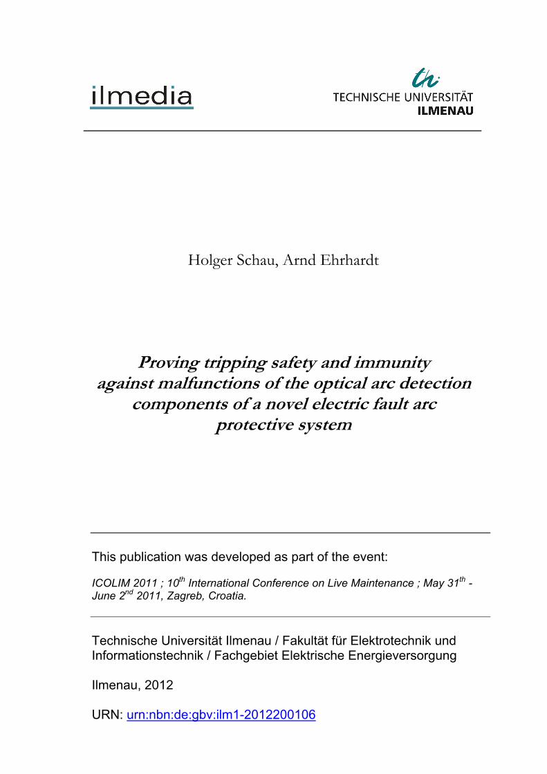
The sensor construction shown in Fig. 7 was found by the several test series to be the optimal variant. It has got only a defined admission zone for arc radiation to be detected. The light sensible sensor heads are optically shielded for preventing tripping due to disturbances by other light sources. Proved in special additional test series, the shields safely prevent a tripping when the permanent light level at the covered sensor areas is above 100.000 lx (tripping threshold) without endangering a reliable fault arc detection in general. In each of the tests arcs were detected as intended, the detection times are not or not significantly influenced respectively. Even a reduction of the detection delay may be achieved by using sensor shields with reflecting inner layers and placing the optically sensible sensor heads in the reflector focal point. Also in case of extremely high background illumination the fault arc detection times are in the range of the minimum delay of about 3.5 ms. It must be remarked, however, that sensor constructions as mentioned last increase the risk of detection malfunction for directly entering high-intensity radiation of ambient or other light sources.
1 m
0,45 m
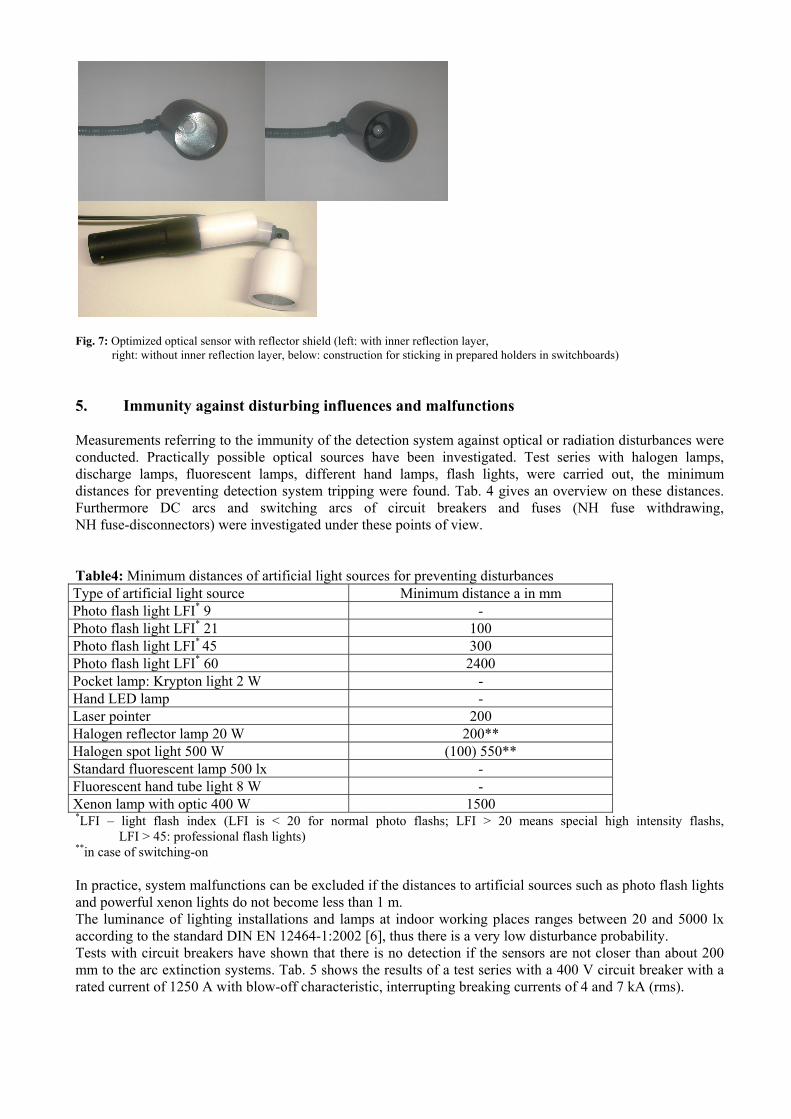
Fig. 7: Optimized optical sensor with reflector shield (left: with inner reflection layer, right: without inner reflection layer, below: construction for sticking in prepared holders in switchboards) 5. Immunity against disturbing influences and malfunctions Measurements referring to the immunity of the detection system against optical or radiation disturbances were conducted. Practically possible optical sources have been investigated. Test series with halogen lamps, discharge lamps, fluorescent lamps, different hand lamps, flash lights, were carried out, the minimum distances for preventing detection system tripping were found. Tab. 4 gives an overview on these distances. Furthermore DC arcs and switching arcs of circuit breakers and fuses (NH fuse withdrawing, NH fuse-disconnectors) were investigated under these points of view. Table4: Minimum distances of artificial light sources for preventing disturbances Type of artificial light source Minimum distance a in mm Photo flash light LFI* 9 - Photo flash light LFI* 21 100 Photo flash light LFI* 45 300 Photo flash light LFI* 60 2400 Pocket lamp: Krypton light 2 W - Hand LED lamp - Laser pointer 200 Halogen reflector lamp 20 W 200** Halogen spot light 500 W (100) 550** Standard fluorescent lamp 500 lx - Fluorescent hand tube light 8 W - Xenon lamp with optic 400 W 1500 *LFI – light flash index (LFI is < 20 for normal photo flashs; LFI > 20 means special high intensity flashs, LFI > 45: professional flash lights) **in case of switching-on In practice, system malfunctions can be excluded if the distances to artificial sources such as photo flash lights and powerful xenon lights do not become less than 1 m. The luminance of lighting installations and lamps at indoor working places ranges between 20 and 5000 lx according to the standard DIN EN 12464-1:2002 [6], thus there is a very low disturbance probability. Tests with circuit breakers have shown that there is no detection if the sensors are not closer than about 200 mm to the arc extinction systems. Tab. 5 shows the results of a test series with a 400 V circuit breaker with a rated current of 1250 A with blow-off characteristic, interrupting breaking currents of 4 and 7 kA (rms).

Three sensors were used in parallel in various distance a from the blow-off system in each test. No sensor indicated the switching arc in the series. Table 5: Results of sensor immunity tests with a 1250 A LV circuit breaker Test No.
Sensor distance a in mm
Breaking current (rms) in kA
detection Sensor 1 Sensor 2 Sensor 3
yes no yes no yes no 01 100 4 X X X 02 100 4 X X X 03 100 4 X X X 04 100 4 X X X 05 50 4 X X X 06 50 4 X X X 07 50 4 X X X 08 50 4 X X X 09 100 7 X X X 10 100 7 X X X 11 100 7 X X X 12 100 7 X X X 13 50 7 X X X 14 50 7 X X X 15 50 7 X X X 16 50 7 X X X
In case of outdoor applications of the detection system significantly higher light intensities occur due to direct and indirect sun radiation particularly. Hence, investigations were made regarding the construction of the optical sensors and the optimization of the necessary sensor shields. By means of the distinguished extensions in the sensor construction described above (special shielding and reflecting constructions for surpressing disturbance light and amplification of arc light receiving) ways to improve the sensor immunity and to shorten the tripping delay were tested and evaluated under critical detection conditions (low arc light intensity, sensor positioning at the limits of direct exposure, high background luminance level, disturbance light reflections) also for outdoor conditions. Tripping malfunctions can practically be excluded to a wide extend by additional use of working walls and coverings preventing a direct illumination of the special sensors by the sun. Another potential source of disturbances of the detection system are open breaking arcs in case of switching processes connected with withdrawing of fuses in electric branches under load. Such processes may also belong to those working activities why the protective system is to be used. The influences of these electric arcs on the detection system are investigated in special test series at opened main distribution boards in connection with optimized sensor positions guaranteeing fault arc detection in the overall equipment when a person is working there (see Par. 7). In general, the risk of unintended tripping can be kept small or in acceptable limits by paying attention to a couple of handling restrictions. Radiation to the optical sensible sensor parts by direct luminance or caused by reflection with more than 9.000 lx from artificial light sources and sun light has to be prevented. This can be reached by definition of minimum distances of the lighting equipment, by positioning of the sensors (height, direction) and by protection walls. In general in indoor applications of the detection system malfunctions of system tripping can practically be excluded, the detection system may be used indoor without any further restrictions.

6. Positioning of the optical sensors for indoor applications Detection itself and the detection time are mainly dependent on the short-circuit current and the sensor distance to the arc. In case of very small short-circuit currents, short detection delay can only be guaranteed when there is no covering or shadowing of the optical sensor but a direct irradiation. The optical sensors have to be positioned under consideration of the specifics of the construction of the power equipment, the short-circuit current range and the working activities as well. The sensors have to be directed to the complete sector area where work is done and may not be covered or shadowed by the electrician when the work is done. Several sensors have to be used with maximum distances of 2 m (or 6 m in case of optimized sensor constructions) to the detection region as found in Par. 3. They have to be directed in such a way that at minimum one of the sensors is directly irradiated by an fault arc in each working position. For practical use special holders for the sensors were developed. In addition, the sensor-shield constructions have a swivelling stick for easily sensor alignment. Effortful investigations are necessary to find the base positions and exact alignment of sensors in real equipment constructions. Such investigations were made for a switchboard with switchable fuse-disconnectors as used in main distribution centres or cable distributors. A dummy in different positions (kneeing, standing) was simulating the workers influences. Three sensors were found to be used: 2 main sensors in the top sector and an additional one in the bottom range ( Fig. 8 to 10 show these base positions). Also the tolerance ranges of these positions were determined.
Fig. 8: Auxiliary tool with holder (left) and illumination ranges resulting from use in the optimized sensor positions in a switchboard (right)

Fig. 9: Light source test for aligning the 3 sensors in the switchboard Based on these experiences procedures were derived for sensor positioning in general. A simple method for fast adjusting of the optical sensors (sensor-shield constructions) exists in using, instead of the sensors, an auxiliary tool. The tool consists of a point light source (e.g. halogen lamp 12 V, 50 W) replacing the optically sensible sensor head in the sensor shield construction and also located in the focal-point of the shield with an inside reflecting layer. Fig. 8 shows this special tool together with the swiveling part of the sensor holder where it to be stuck in. The light illuminating cone resulting from this source indicates the zone where in a fault arc, if existing there, would result in a direct irradiation of the optical sensor. The appropriate sensor positioning and alignment for the application under study has been found when all parts of the protection zone (area) are illuminated by the auxiliary tool at minimum once at the different sensor places selected. Fig. 8 shows the illumination areas representing the protection sectors in the switchboard mentioned above. Fig. 9 illustrates the “light-source tests” verifying the 3 optimized sensor positions for this example. The method is mainly useful in sensor position in existing power equipment. The second method consists in finding the base sensor positions by using 3-D-CAD software. Base is a 3-D model of the power equipment (e.g. switchboard). The sensor positions have to be varied in simulation variants as long as the complete protection zone is covered by the illumination cones resulting from the sensors planned. The equipment construction and optical obstacles such as worker positions have to be taken into account in these calculation variants. The virtual illumination cones result from the opening space angle of the sensor shields. The sensor place and alignment found as the result is described by space coordinates related to a defined coordinate and scale system. In the real installation to be equipped by sensors, first, an auxiliary tool in form of a laser pointer is fixed at the sensor holders. The sensor holder swiveling part is aligned to hit the coordinates found by simulations. After that the sensor-shield constructions are mounted to the holders aligned. This method is particularly suitable for use in the planning phase of equipment. The check by means of a laser pointer can also be applied after maintenance or revision of power equipment. Necessary prerequisite is that check coordinates were provided in the equipment planning phase.
Sensor 1 Sensor 2 Sensor 3

7. Detection system response when withdrawing fuses under load The detection system immunity against optical disturbances when fuses are switched-off under load by persons (withdrawing fuses) was investigated in a real main distribution board (type-tested equipment) with NH fuse-disconnectors. It was analyzed whether the normal manual switch-off activity associated with an open breaking arc results in an unintended tripping signal. A fuse-withdrawing robot was used to switch-off an electric load circuit with defined load current (test current). Fig. 10 shows the switchboard with the robot. Both, a single-phase load circuit and a 2-phase one with ohmic-inductive load were connected to one of the downstream out-going fuse-disconnector branches. In the single-phase circuit the load is connected phase-to ground (test voltage 230 V) to simulate the fuse conditions in a 400 V system. With the 2-phase circuit connected phase-to-phase (test voltage 400 V) 690 V system conditions are considered. The R/X ratio of the load circuit impedance was varied. Together with the load current switch-off angle the R/X has influence on the formation and energy of the breaking arc and, consequently, on its radiation intensity. The pneumatic control system of the robot used does not allow to adjust certain current switch-off angles. The angles are randomly varying, each of the parameter settings was repeated 6 times in order to have also extreme cases of switch-off arcs in the according test series.
Fig. 10: Switchboard with NH fuse-disconnectors and withdrawing robot The optical sensors of the detection system were placed in the basic positions found by optimization for the special switch board construction. Three sensors were used (Fig. 10). Before considering the fuse disconnection effect the intended function of the detection system is proven in two steps. First the professional photo flash device Mecablitz 60 CT (light flash index 60) was used to trip the detection system by direct flashing each of the sensors (exposure distance of about 10 mm). After that, a short electric arc was fired between auxiliary electrodes of small distance for testing the safe detection system function (Fig. 11). A very low-intensity arc was formed with a prospective current of about 1 kA (arc power 36.1 kW). The arc was detected within 18.2 ms, the sensitivity of the arc detection system is verified. In the fuse withdrawing tests 1-pole switchable fuse-disconnectors NH 00 160 A and NH 2 400 A with fuses gL/gG 500 V AC or 690 V AC of different manufacturers were used. Fuse cartridges with contacts of copper as well as brass were investigated to cover different contact material influences. The tool for withdrawing the fuse cartridges is a robot as used in fuse testing. In fuse testing the standard withdrawing speed is about 0.5 ms-1. A trained skilled electrician attains about 2.0 ms-1. In the fuse withdrawing tests under study the average speed was 0.64 ms-1. That is less than the normal working speed. Thus the test conditions regarding the time period of arc existence are more critical than those to be expected in reality (longer arc duration).

The test parameters and results of the several series (each with 6-fold repetition) are summarized in Tab. 6. The Tab. 6 shows that mainly test currents (load currents) representing over-current conditions (up to over-current ratios of more than 3) were adjusted. That means worst case conditions regarding the breaking arcs, too.
Fig. 11: Switchboard location where the arc is ignited fo rthe functional test (above) and test oszillogram cinfirming the detection (below)
Fig. 12: Fuse withdrawing test No. 19 (according to Tab.6) with oszillogram
i_L3_LB i_L3_KS u_L2L3 u_Auslöse
-1.00
0.00
1.00kA
-200
-100
0
100
200V
0.05.0
10.015.020.0
V
0 5 10 15 20 25 30 35 40 45 50 55 60 65 70 75 80
ms
i_L1 u_L1N
-1.50-1.00-0.500.000.501.001.50
kA
-450-300-150
0150300450
V
0 5 10 15 20 25 30 35 40 45 50 55 60 65 70 75 80
ms
auxiliary electrodes for arc ignition
Tripping signal
phase-to phase voltage
tV = 18,2 ms
short circuit unit current
Arc current
load current
fuse voltage

In the tests the breaking arcs last between 1 to 3 current half-cycles. Fig. 12 shows an example. In all cases (120 tests) the according radiation was not sufficient to detect the arc and trip the protective system. Because 3 sensors were active in each test the system immunity against these arcs is verified in 360 exposures. Due to the parameter variation it can be concluded that withdrawing fuses under load will practically not result in protection system malfunctions (unintended tripping). Table 6: Test of withdrawing fuses for verification of the system immunity
test NH fuse Load circuit Optical detection
No. type Rated current Ir in A
Contact material
Voltage in V
Test current in A
R/X 6 tests, 3 sensors each
1 NH 00 160 Cu 230 280 0,26 No 2 NH 00 160 Brass 230 280 0,26 No 3 NH 00 160 Cu 230 540 0,25 No 4 NH 00 160 Brass 230 540 0,25 No 5 NH 00 160 Cu 400 440 0,32 No 6 NH 00 160 Brass 400 440 0,32 No 7 NH 2 400 Cu 230 100 5,66 No 8 NH 2 400 Brass 230 100 5,66 No 9 NH 2 400 Cu 230 200 3,21 No
10 NH 2 400 Brass 230 200 3,21 No 11 NH 2 400 Cu 230 250 2,62 No 12 NH 2 400 Brass 230 250 2,62 No 13 NH 2 400 Cu 230 400 1,53 No 14 NH 2 400 Brass 230 400 1,53 No 15 NH 2 400 Cu 230 700 0,46 No 16 NH 2 400 Brass 230 700 0,46 No 17 NH 2 400 Cu 230 1300 0,51 No 18 NH 2 400 Brass 230 1300 0,51 No 19 NH 2 400 Cu 400 1200 0,47 No 20 NH 2 400 Brass 400 1200 0,47 No
8. Summary The optical arc detection system investigated shows very high detection reliability. It provides very short detection times. There is practically no risk of malfunction (unwanted tripping) when used indoor. The necessary high optical immunity (safety against optical disturbances) may be increased by means of working instructions which forbid a direct exposure of the optically sensitive sensor heads by artificial light sources within short distances. Besides artificial light sources, switching arcs inside circuit breakers of the equipment do not affect the detection system. By laboratory tests it was furthermore verified that system will not be tripped if there are open breaking arcs resulting from manual operational switching-off of electric branches under load by withdrawing fuses as carried out in the frame of typical working activities in opened power equipment. The detection system can also be used in outdoor applications. It is necessary to prevent sensor exposure to sun light by erecting working walls and covers to shield the working or protection area respectively. An essential prerequisite of a fast arcing fault detection is the optical sensor to be exposed directly to the arc irradiation. In practical applications this can become possible by using several sensors at different positions covering the working zone of the opened equipment. In general 3 sensors are sufficient. The appropriate sensor positions and alignment have to be determined and optimized. The detection time is an essential factor regarding the total tripping time of the protection system. Short detection time means generally also a very fast extinction of the fault arc. Detecting fault arc is relatively uncritical in case of high short-circuit currents and arc power, a minimum detection time is achieved. The critical case is represented by fault conditions at the borderline of arc existence

(prospective short-circuit currents of about 1 kA). Under these critical conditions the detection time is increased but not longer than 20 ms for optimized sensor positioning. For short-circuit currents of 7 kA or more the detection time is about 3.5 ms. Based on this, the following total operating times of the protective system (detection and extinction of the arcing fault) are typical: about 20 ms for short-circuit currents of 1 kA, about 8 ms with 7 kA and about 5 ms with 25 kA. The arc detection and extinction times provided by the protection system keep the remaining thermal arc consequences extremely small and wide below the tolerance limits of personal protection (personal injury) [7]. 9. References [1] Schau, H.; Ehrhardt, A.: Quenching arcing faults via a short-circuiter during live working up to 1000 V. 9th International
Conference on Live Maintenance (ICOLIM), June, 4-6, 2008, Torun/Poland, Session S3, Proceedings pp. 72 – 84 [2] Schau, H.; Ehrhardt, A.: Einsatz von Kurzschließern zum Schutz von Personen beim AuS. 7. Fachtagung "Arbeiten unter
Spannung (AuS)", Dresden, Sept. ,19-20, 2007, ETG-Fachbericht vol. 106, 2007, pp 83 – 90 [3] Meyer Industrie-Electronic GmbH Lengerich: LBW21 - Intelligentes Licht Informationssystem. Betriebsanleitung11/2004
u. Montageanleitung 12/2004
[4] Ehrhardt, A.; Schau, H.: Proving of the tripping safety of a novel device for arc flash protection. 54th Intern. Scientific
Colloquium (IWK), Technische Universität Ilmenau, Sept., 7-10, 2009, Session 6.5, Proc., 8 pages [5] DIN IEC 61482-1-2 (VDE 0682-306-1-2): Arbeiten unter Spannung – Schutzkleidung gegen die thermischen Gefahren
eines elektrischen Lichtbogens – Teil 1-2: Prüfverfahren – Verfahren 2: Bestimmung der Lichtbogen-Schutzklasse des Materials und der Kleidung unter Verwendung eines gerichteten Prüflichtbogens (Box-Test), December 2007
[6] DIN EN 12464-1: 2003-03: Licht und Beleuchtung - Beleuchtung von Arbeitsstätten, Teil 1: Arbeitsstätten in Innenräumen [7] Bombik, S.; Ehrhardt, A.; Rotter, G.; Rock, M.: Modulares Störlichtbogenschutzsystem DEHNarc, 8. Fachtagung
"Arbeiten unter Spannung (AuS)", Dresden, Sept., 14-15, 2010, ETG-Fachbericht vol. 123, 2010, pp 35 – 42.