providing gbps/user connectivity in...
TRANSCRIPT

ACM SRC Entry: Candy Yiu ([email protected]) Portland State UniversityResearch Advisers: Prof. Suresh SinghCategory: Graduate
Providing Gbps/User Connectivity in WLANs
Problem and Motivation
It is clear that people have an insatiable appetite for higher and higher data rates. Indeed, bandwidth hungry applications like HDTV(High Definition TeleVision), graphic intensive online games, and network attached storage for high resolution content demand gigabitlinks. Since most applications delivered over the internet pass through at least one wireless hop, for convenience, newer wirelesstechnologies have been created to satisfy this need. For instance, wireless technologies such as MIMO (MultipleInput and MultipleOutput, 802.11n) and WiMAX (Worldwide Interoperability for Microwave Access, 802.16e) can provide up to 70300Mbps in the 2.4GHzand 5GHz bands. However this data rate is shared among multiple users. Even in the ideal case, when there is no overhead due totransmission coordination, these rates are still far from having gigabit links per user.
Our research goal is to provide Gbps/user wireless data rate in indoor environments. However, there are two significant hurdles thatneed to be overcome we need a large amount of available bandwidth and we need to be able to scale the data rate as the number ofusers increases. The newly opened 60GHz ISM (Industrial, Scientific and Medical) band is ideally suited to meet these challengesbecause there is between 57GHz of available bandwidth and this part of the spectrum is amenable to efficient spatial reuse. This isbecause the 60GHz frequency band is highly absorbed by oxygen and by most building materials, in addition to being poorly reflected.Thus, the same channel can be reused many times within a room.
Our approach uses the almost raylike propagation of signals in this band to view the traditional resource allocation problem in ageometric manner. Consider a typical room containing arbitrary obstructions and different user locations. The problem is to createspatial channels to maximize per user throughput. The challenge comes about because the shape of the spatial channels, created bysmart antennas, is complex and varies according to the beamforming angle. A sideeffect is that a naive approach of beamformingtowards individual users yields very poor throughput due to nonuniform groupings of users to channels and the resulting increase ininterference. We consider the problem of jointly creating spatial channels and assigning users to the channels in order to maximizethroughput while ensuring fairness.
Background and Related work
Providing Gbps/user wireless connectivity in indoor environments is an exciting problem that has received much attention in the recentpast. Unlike lower frequency bands (typically between 2 and 6 GHz) used in 802.11, the 60GHz band has unique propagation properties.This band is very well absorbed by oxygen, and reflections are severely attenuated. A comparison of the LoS (Line of Sight) path tofirstorder reflections is addressed in [langen94] for typical indoor environments. A clear conclusion is that the strongest reflections(from windows) are almost 10dB below the LoS path. If the surface is not polished, then the reflected component is much weaker. Thepenetration losses are also severe with many building materials such as concrete causing a 35dB reduction in signal strength. Becauseof these properties, as noted in [felbecker08,lim07,smulder04], the propagation at this frequency can be considered raylike with ameasured path loss exponent of 2.1 [xu02,anderson04].
The severely contained propagation of this frequency and high degree of attenuation has led various authors [smulders02,xu02] tosuggest using highly directional antennas between the access point and users. Using such antennas mitigates the problem of signalattenuation while, simultaneously, allowing spatial reuse. SDMA (Spatial Division Multi Access) has been studied over the past decadeand numerous algorithms have been developed. However, all previous works look at a much lower frequency (25GHz) where multipathcomponents are significant. Thus, a great deal of previous work [hoymann06,kou06,kuz06] develops MIMO/SDMA algorithms to identifythe strongest multipath components in a room and combine them to achieve high data rates. In 60GHz, since multipath is negligible,these previous algorithms are not applicable.
In [singh07], the author presents a MAC (Media Access Control) design for a multihop 60GHz WPAN (Wireless Personal Area Network).Every node uses highly directional antennas and high transmit power to maintain a networkwide rate of 2Gbps when usingapproximately 66% of the available bandwidth. However, the paper does not consider the attenuation due to different materials thatmay obstruct the signal path (including the human body). Furthermore, the antenna model used assumes a fixed 10dB gain in thedirection of the main beam with no sidelobes and interference from reflections and other transmissions are not considered. In our work,we use realistic propagation models and accurate antenna models to study the problem of reaching Gbps/user data rates. Ouralgorithms exploit the welldefined shape created at the intersection of the floor and antenna pattern to reuse the spectrum efficiently.We also exploit the geometric properties to repair broken links by using passive reflectors. These and other innovations are describedin the following section.
Approach and Uniqueness
To explain our approach, we list the technical challenges inherent in creating 60GHz WLANs and follow each challenge with our solution.
Challenge 1: 60GHz has poor propagation with an attenuation of 88dB/10 meters resulting in very low received power and henceachievable data rate.

Solution: Use smart antennas at both the users and access point. This gives us higher received power by increasing the transmit andreceive antenna gains. The received power (in dB) can be written as:
Prx = Ptx + Grx + Gtx 20 log 10(4 π r/ λ)Prx received powerPtx transmit powerGrx receiver gain
Gtx transmitter gainλ wavelength
r distance between transmitter and receiver
Smart antennas (also called antenna arrays) consist of multiple antenna elements. They focus bit energy towards the direction ofinterest while forming nulls towards interference sources. Assume that the smart antenna has M elements, it can form up to M1 nulls.Figure 1(a) shows a 2 element array with distance d separation. As we can see, the signal hitting the first element travels a distanced/2sinθ greater than the distance to the second element. Digital beamforming allows us to form beams in arbitrary directions byweighting and phase shifting each signal prior to summing them together. The array factor for the linear array is calculated using theequation in Figure 1(a). Figure 1(b) shows the beam formed when using a linear array with 20 elements beforming from the center ofthe ceiling to the coordinates (1.5m,1.5m,0.5m) in 3dimensions. The antenna gain we get with 20 elements ranges from 1114dBdepending on user location.
Figure 1(a) Figure 1(b)
Challenge 2: Creating spatial channels to users individually by beamforming towards them yields poor throughput due to nonuniformgrouping of users and an increase in interference between users due to nonuniform beam shapes. Figure 2(a) shows the spatialchannels formed when beamforming towards user A and B individually. As we can see, A lies within B's beam and B lies within A'sbeam resulting in high interference if they are both assigned to the same channel. An alternative way is to beamform at an angularoffset such that each user is within 3dB of the maximum gain of its beam but has lower interference from the other beam. By doing thiscarefully, it is possible to maximize channel reuse. Figure 2(b) shows nonoverlapping beams which allow A and B to transmitsimultaneously with significantly reduced mutual interference.
Figure 2(a) Figure 2(b) Figure 2(c)
Solution: Finding the optimal placement of channels as in Figure 2(b) for arbitrary user placements is computationally expensive. Anefficient solution that we developed is to statically divide the room into 3dB nonoverlapping regions. A region is defined as theintersection of the floor with the beam such that the gain at the edge of the region is 3dB below the maximum gain at the center of theregion. We identify the minimum number of beamforming angles such that the set of regions covers the entire room. Figure 2(c) showsa room of size 10mX10m and the 21 regions formed when using a linear array of 20 elements.
A smart antenna can have multiple beamforming modules. A beamforming module can form a beam in one direction while nulling up toM1 other directions (where M is the number of antenna elements). If we have 21 beamforming modules, for example, we can coverthe entire room shown in Figure 2(c) by using one module per region (of course, the interference between adjacent regions will behigh). Given this capability, we can state the general problem as follows: for a given room geometry and antenna array size, whatchannel allocation and transmission schedule maximizes data rate if the number of beamforming modules is unrestricted? For example,given K modules at the access point, we can simultaneously cover K regions (out of 21, in our example). Therefore, we require 21/K

slots to cover the entire room and simultaneously active regions are separated by 21 mod K regions. By varying K we can determinethe optimal value of K that maximizes data rate. In our example, a maximum data rate of 8 Gbps is obtained when K=8.
Challenge 3: The beams that are formed, when using antenna arrays, have a complex shape resulting in variable gain even within thesame region. They also exhibit a significant amount of sidelobes (energy in unwanted directions) causing interference between regions.These two properties imply inefficient spatial reuse.
Solution: To maximize spatial reuse, we develop a novel M1 nulling method to greatly reduce interference between regions. Let M bethe number of elements in the array and K be the number of beams being formed. We beamform at the center of each region and nulleach of the (K1) other regions using (M1/K1) nulls equally spaced in the region. In Figure 3, the orange line shows the antenna gainwhen beamforming at region 1 and nulling region 11 using 19 nulls. Similarly, the dotted blue line shows the case when we beamformto region 11 and null region 1. Observe that the interference between region 1 and 11 is less than 110dB across the entire region. Inthe case when we only form one null, as is commonly done, the interference is at least 34dB. Given that thermal noise (174dBm/Hz)for a 640MHz bandwidth is 86dBm, we note that our approach reduces interference to the level of noise.
Figure 3
Challenge 4: Recall that this frequency is well absorbed by oxygen [marcus05] which means that human activity within the room willfrequently lead to link breakages. Unlike other frequency bands, multipath here is minimal, and thus there are few alternatives that onecan fall back upon to repair the failed links.
Solution: We use passive reflectors located on the walls of the room to provide alternative paths when needed. Some materials such aswire mesh glass only attenuate the 60GHz signals by 3dB and therefore are good choices for reflectors. The static regions we describedin Figure 2(c) are still used but when a user's LoS is blocked, we simply connect the user via the reflected path from another region.
Results and Contributions
We built a detailed indoor propagation model using ray tracing in Matlab. The reflection and transmission attenuation data from[langen94] was incorporated into the model. For any given room configuration, the model provides accurate signal strength informationfor any pair of transmitter and receiver locations. The model includes the LoS path and the first order reflections from all reflectivesurfaces. Therefore, we also obtain accurate signal strength data for total interference at all points in the room for any arbitrary set oftransmitters. Figure 5(a) shows some of the first order reflections in an empty room where the transmitter is the access point at thecenter of the ceiling. The propagation model we developed is used for all of our experiments.
Interference Mitigation
In order to maximize data rates in our architecture, we allow multiple regions in the room to be active at the same time. Therefore,nodes will see interference from three sources:
1. Interference from the sidelobes of the beam formed by the antenna towards other regions.2. Interference from the first order reflection of the desired signal that arrives later than the symbol time (2.5ns). Figure 5(b) in redshows this intersymbol interference while the white shows the reflection that arrives within the symbol time and hencecontributes to total signal strength.
3. Interference from the first order reflection of all the other simultaneous transmissions.

Figure 5(a) Figure 5(b)
We use three techniques to combat interference:
The distance of the access point to different parts of the room ranges from 3 to 8 meters. Therefore, we use differenttransmission powers in different regions to reduce interference to other regions. The transmission power (in dB) is computedusing the following link budget calculation:
Sensitivity = Noise + Bandwidth + RXnoise + SNRminRXnoise noise figure in the receiver circuits
SNRmin minimum Signal to Noise Ratio requirement
If we use 64QAM (Quadrature Amplitude Modulation) as an example, to achieve a target BER (Bit Error Ratio) of 10^(6), werequire a SNR_min (SignaltoNoise Ratio) of 23.4dB for a Rx_noise figure of 10dB and standard thermal noise of 174dBm/Hz.From this we can calculate the minimum required transmit power (in dB) for region i as:
Ptx(i) = max Ptx(d,i) = max(Sensitivity Gtx(i) Grx(i) Path Gain(d,i))Ptx transmit power
Ptx(d,i) transmit power required for a receiver at distance d from the AP in region iGtx antenna gain at transmitterGrx antenna gain at receiver
Path Gain attenuation with distance for this frequency
Figure 6 shows an example of transmit power for the case when using 64QAM with BER requirement of 10^(6). In oursimulations, we considered four different modulation schemes listed below. The modulation used for a given user is the one thatmaximizes data rate within the BER constraint of 10^(6).We use 1/2 or 3/4 convolution codes (constraint length 8) to get an additional gain of between 37dB.Each antenna module has M=20 elements. We use the M1 nulling idea described previously to reduce the sidelobe interference.
Figure 6
Measured Throughput
We use the following table for our experiments.

Room Dimension 10m x 10m x 3mAP Location Center of the ceiling
Transmit Power 10dBmChannel Bandwidth 640MHzAdaptive Modulation 64QAM, 16QAM, QPSK, BPSKAntenna Elements 20
QAM: Quadrature Amplitude ModulationQPSK: Quadrature Phaseshift Keying
BPSK: Binary Phaseshift Keying
Figure 7
Figure 7 shows the data rate obtained as a function of the number of users when we use 7 channels (each 640MHz). The plot labeled"static" corresponds to our STDMA (Spatial Time Division Multiple Access) algorithm while the "dynamic" corresponds to the greedyalgorithm where no regions are used and we beamform towards individual users. We see a linear scaling for our algorithm while thedynamic algorithm's performance falls when there are too many users. The reason was previously discussed in the context of Figure2(a). When there are 10 users in the system, our approach delivers 1 Gbps/user data rate but this falls to 600Mbps/user when there are50 users. The reason is increased interference between simultaneous transmissions. However, recall that these numbers are based onsimulations for a room size of 10m x 10m. Placing 50 users in such a small room is unrealistic and therefore one can argue that ourscheme does provide Gbps/user for realistic room usage scenarios. Another way of looking at the result is that we achieve anaggregate data rate of 30Gbps in the room which translates to 300Mbps per meter square.
Measured Power
In order to study energy scaling with data rate, we varied the number of modules from 1 to 21 for the 10mx10m room. Figure 8(a)plots the energy per bit as a function of the number of modules K. When K is small, we get a low energy cost because there is littleinterference between simultaneously active regions. As the number of modules increases, more regions are simultaneously activecausing higher interference. However, when K is less than 13, the gain in throughput offsets the increased energy cost due tointerference. When K is greater than 13, the interference is much more significant resulting in high energy per bit. The reason for this isthat by forming M1 nulls, we force the main beam to shift slightly thus lowering gain in the direction of the desired signal, Figure 8(b).Finally, when K is greater than 15, there are more regions towards which we form only 1 null and therefore the behavior illustrated inFigure 8(b) is less pronounced. This results in higher signal strength in the main beam and the corresponding decrease of energy per bitillustrated in Figure 8 (a).
Figure 8 (a) Figure 8 (b)
Repairing Links using Reflectors
Links are easily broken by user mobility or by obstructions. As discussed previously, we use wall mounted passive reflectors to repairlinks. Figure 9 shows the throughput for each region when region 1, 4 and 13 are covered by reflected paths. Note that the throughputfor the reflected paths is lower because the path is longer than the LoS paths and the signal is attenuated by 3dB when reflected.Region 13 has the lowest throughput since it is in the center of the room and thus suffers the highest interference in addition to loweredsignal strength due to the longer path.
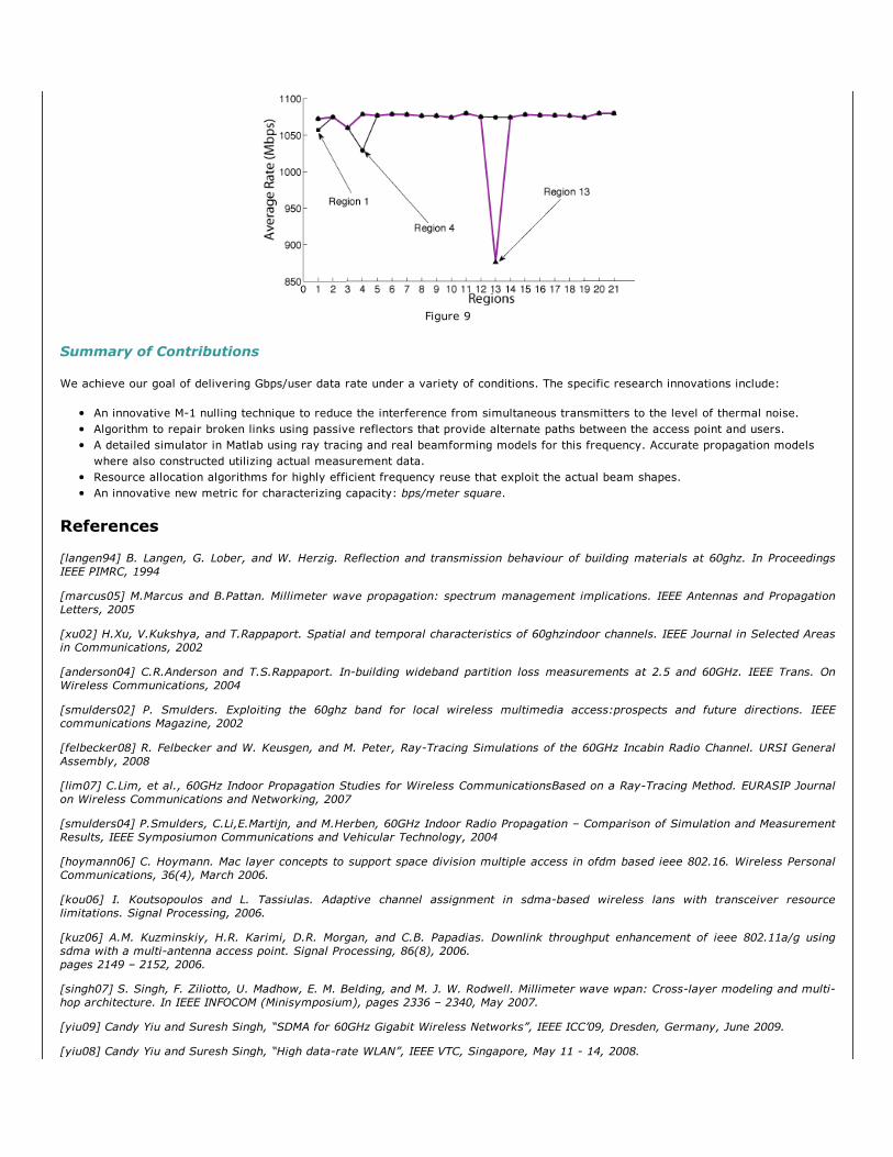
Figure 9
Summary of Contributions
We achieve our goal of delivering Gbps/user data rate under a variety of conditions. The specific research innovations include:
An innovative M1 nulling technique to reduce the interference from simultaneous transmitters to the level of thermal noise.Algorithm to repair broken links using passive reflectors that provide alternate paths between the access point and users.A detailed simulator in Matlab using ray tracing and real beamforming models for this frequency. Accurate propagation modelswhere also constructed utilizing actual measurement data.Resource allocation algorithms for highly efficient frequency reuse that exploit the actual beam shapes.An innovative new metric for characterizing capacity: bps/meter square.
References
[langen94] B. Langen, G. Lober, and W. Herzig. Reflection and transmission behaviour of building materials at 60ghz. In ProceedingsIEEE PIMRC, 1994
[marcus05] M.Marcus and B.Pattan. Millimeter wave propagation: spectrum management implications. IEEE Antennas and PropagationLetters, 2005
[xu02] H.Xu, V.Kukshya, and T.Rappaport. Spatial and temporal characteristics of 60ghz indoor channels. IEEE Journal in Selected Areasin Communications, 2002
[anderson04] C.R.Anderson and T.S.Rappaport. Inbuilding wideband partition loss measurements at 2.5 and 60GHz. IEEE Trans. OnWireless Communications, 2004
[smulders02] P. Smulders. Exploiting the 60ghz band for local wireless multimedia access: prospects and future directions. IEEEcommunications Magazine, 2002
[felbecker08] R. Felbecker and W. Keusgen, and M. Peter, RayTracing Simulations of the 60GHz Incabin Radio Channel. URSI GeneralAssembly, 2008
[lim07] C.Lim, et al., 60GHz Indoor Propagation Studies for Wireless Communications Based on a RayTracing Method. EURASIP Journalon Wireless Communications and Networking, 2007
[smulders04] P.Smulders, C.Li,E.Martijn, and M.Herben, 60GHz Indoor Radio Propagation – Comparison of Simulation and MeasurementResults, IEEE Symposiumon Communications and Vehicular Technology, 2004
[hoymann06] C. Hoymann. Mac layer concepts to support space division multiple access in ofdm based ieee 802.16. Wireless PersonalCommunications, 36(4), March 2006.
[kou06] I. Koutsopoulos and L. Tassiulas. Adaptive channel assignment in sdmabased wireless lans with transceiver resourcelimitations. Signal Processing, 2006.
[kuz06] A.M. Kuzminskiy, H.R. Karimi, D.R. Morgan, and C.B. Papadias. Downlink throughput enhancement of ieee 802.11a/g usingsdma with a multiantenna access point. Signal Processing, 86(8), 2006.pages 2149 – 2152, 2006.
[singh07] S. Singh, F. Ziliotto, U. Madhow, E. M. Belding, and M. J. W. Rodwell. Millimeter wave wpan: Crosslayer modeling and multihop architecture. In IEEE INFOCOM (Minisymposium), pages 2336 – 2340, May 2007.
[yiu09] Candy Yiu and Suresh Singh, “SDMA for 60GHz Gigabit Wireless Networks”, IEEE ICC’09, Dresden, Germany, June 2009.
[yiu08] Candy Yiu and Suresh Singh, “High datarate WLAN”, IEEE VTC, Singapore, May 11 14, 2008.

This project is funded by NSF grant 0722008