providing customer quality with testing and monitoring · customer quality with testing and...
TRANSCRIPT

Providing
Customer
Quality with
Testing and
Monitoring
1.19.2016

2 2
Agenda
New Technology
Fiber
RF Networks
Customer Networks

© 2015 Viavi Solutions, Inc. | Viavi Confidential and Proprietary Information 3
Growing Services Consuming HFC Spectrum
More HD Video Services ▫ Growth plans to 100+ HD channels
More SD Video Content ▫ Expansion to nx100 SD chs to compete w/ satellite
Personalized Video Services ▫ Migration from Broadcast to Unicast services
▫ VoD, Startover, MyPrimetime, etc
Broadband Internet Services Growth ▫ Migration from Web to Web2.0, Video Streaming and P2PTV
Applications
▫ Increased per home BW consumption
▫ Expansion of the peak hour to whole evening
IoT – Internet of Things
Competitive pressure!

© 2015 Viavi Solutions, Inc. | Viavi Confidential and Proprietary Information 4
Seeing the Future
Source: Pipeline Magazine
STREAMING VIDEO DOMINATES WEB TRAFFIC
Nearly60% by 2015

© 2015 Viavi Solutions, Inc. | Viavi Confidential and Proprietary Information 5
337.6
MOBILE POWER USERS CLOG NETWORKS
389.1
435.3
525.5
606.1
Seeing the Future
Average monthly data usage
per user (MB)
Average monthly
per-user data
consumption by
U.S. smartphone
customers jumped
80% from the third
quarter of 2010
to the third quarter
of 2011. Source: The Nielsen Company

© 2015 Viavi Solutions, Inc. | Viavi Confidential and Proprietary Information 6
EXPLOSION IN CONNECTED DEVICES:
Seeing The Future
Source: Ericsson, 2011
T0 500
BILLION
BY 2020

© 2015 Viavi Solutions, Inc. | Viavi Confidential and Proprietary Information 7

© 2015 Viavi Solutions, Inc. | Viavi Confidential and Proprietary Information 8
RF Network Changes
Docsis 3.0
32 Downstream 8 Upstream
Docsis 3.1
192 Mhz Channel Downsteam
24Mhz channel upstream.
OFDM Modulation – More Robust
Plant Design Changes
RFog
Node plus 1 Active or Node passive
Return path spectrum to 85 Mhz or 200 Mhz
Downstream Path Spectrum to 1.2 Ghz or 1.8 Ghz
Source: SCTE

© 2015 Viavi Solutions, Inc. | Viavi Confidential and Proprietary Information 9
SCTE Docsis 3.0 Downstream RF Spec – 32 X 8 Bonded
Source: SCTE

© 2015 Viavi Solutions, Inc. | Viavi Confidential and Proprietary Information 10
SCTE Docsis 3.1 Downstream RF Spec – 192 Mhz Channel
Source: SCTE

© 2015 Viavi Solutions, Inc. | Viavi Confidential and Proprietary Information 11
Voice Quality Impairments – it’s not always the plant!
PSTN
Cable
CMTS
CMTS
CMTS
Aggregation
switch
Core IP
Network
HUB SITE
MEDIA POP
MEDIA POP
Trunk Media
Gateway
Trunk Media
Gateway
Cable
Modem
MTA POTS
Phone
HOME Background noise, handset
speaker/mic interference,
inadequate volume, inside
wiring, mis-configured MTA
(CoS-Diffserv / firewall
settings), wireless phone
delay exacerbates echo
problems, MTA DSP/echo
canceller performance
CABLE PLANT RF downstream and/or
upstream errors leading to
IP packet loss, bandwidth
capacity limitations (esp.
upstream) may lead to
CMTS congestion (dropped
IP packets) and excessive
jitter (packet drops by codec)
Customer
Problem? Cable Provider
Problem?
HUB SITE Excessive NE polling
and/or high utilization
lead to congestion
causing jitter, dropped
packets and increased
transit delay
UPSTREAM or
DOWNSTREAM?
What’s the
problem?
CORE IP NTWK High utilization lead to
congestion causing jitter,
dropped packets and
increased transit delay,
mis-configured routing
can cause inappropriate
hops leading to increased
latency
MEDIA GW POP DSP codec
performance, echo
canceller config., jitter
buffer config. / packet
drops
Telco
Problem?
PSTN analog problems on PSTN
path passed through to IP
network
Cable Provider
Problem?
Where is the Problem?
What is the Problem?
CMTS-Blade-
Port or Switch-
Slot-Port?
What’s the
problem?
Router-Slot-
Port?
LSP/VLAN,
Route?
What’s the
problem?
MediaGW-
Slot-Port?
DSP Card-
Port-CPU?
What’s the
problem?

12 12
Fiber Testing

© 2015 Viavi Solutions, Inc. | Viavi Confidential and Proprietary Information 13
Where is it? – Everywhere
Airborne, hands, clothing, bulkhead adapter, dust
caps, test equipment, etc.
The average dust particle is 2–5µ, which is not
visible to the human eye.
A single spec of dust can be a major problem
when embedded on or near the fiber core.
Even a brand new connector can be dirty. Dust
caps protect the fiber end face, but can also be a
source of contamination.
Fiber inspection microscopes give you a clear
picture of the problems you are facing.
Your biggest problem is right in front of you… you just can’t see it!
DIRT IS EVERYWHERE!

© 2015 Viavi Solutions, Inc. | Viavi Confidential and Proprietary Information 14
Where is it? – Proliferation of Dirt
Test Equipment
Dust Caps
Bulkheads
People
Environment
There are a number of different sources where dirt and other particles
can contaminate the fiber.
Connectors and ports on test equipment are mated frequently and are highly
likely to become contaminated. Once contaminated, this equipment will often
cross-contaminate the network connectors and ports being tested.
Inspecting and cleaning test ports and leads before testing
network connectors prevents cross-contamination.

© 2015 Viavi Solutions, Inc. | Viavi Confidential and Proprietary Information 15
Types of Contamination
A fiber end face should be free of any contamination or defects, as shown below:
Common types of contamination and defects include the following:
Dirt Oil Pits & Chips Scratches
SINGLEMODE
FIBER

© 2015 Viavi Solutions, Inc. | Viavi Confidential and Proprietary Information 16
16
What Makes a GOOD Fiber Connection?
Perfect Core Alignment
Physical Contact
Pristine Connector
Interface
The 3 basic principles that are critical to achieving an efficient fiber
optic connection are “The 3 P’s”:
Core
Cladding
CLEAN
Light Transmitted
Today’s connector design and production techniques have
eliminated most of the challenges to achieving core alignment and
physical contact, but they are SENSITIVE TO CONTAMINATION!

© 2015 Viavi Solutions, Inc. | Viavi Confidential and Proprietary Information 17
17
What Makes a BAD Fiber Connection?
A single particle mated into
the core of a fiber can
cause significant
back reflection,
insertion loss, and even
equipment damage.
Maintaining a clean connector end face is the real challenge!
As a result, CONTAMINATION is still the #1 source for troubleshooting in
optical networks.
DIRT
Core
Cladding
Back Reflection Insertion Loss Light

© 2015 Viavi Solutions, Inc. | Viavi Confidential and Proprietary Information 18
18
Contamination & Signal Performance
Fiber Contamination and Its Effect on Signal Performance CLEAN CONNECTION
Back Reflection = -67.5 dB
Total Loss = 0.250 dB
1
DIRTY CONNECTION
Back Reflection = -32.5 dB
Total Loss = 4.87 dB
3
Clean Connection vs. Dirty Connection
This OTDR trace illustrates a significant decrease in signal
performance when dirty connectors are mated.

© 2015 Viavi Solutions, Inc. | Viavi Confidential and Proprietary Information 19
19
Proactive versus Reactive Inspection
PROACTIVE INSPECTION:
Visually inspecting fiber
connectors at every stage of
handling BEFORE mating them.
Connectors are much easier to
clean prior to mating, before
embedding debris into the fiber.
REACTIVE INSPECTION:
Visually inspecting fiber connectors
AFTER a problem is discovered,
typically during troubleshooting.
By this time, connectors and other
equipment may have suffered
permanent damage.
Dirty Fiber PRIOR to Mating Fiber AFTER Mating and
Numerous Cleanings
Dirty Fiber PRIOR to
Mating
Fiber AFTER Cleaning

© 2015 Viavi Solutions, Inc. | Viavi Confidential and Proprietary Information 20
Inspect Before You Connect
Follow this simple “INSPECT BEFORE YOU CONNECT” process to ensure
fiber end faces are clean prior to mating connectors.
CONNECT INSPECT
CLEAN
Is it
clean?
NO YES

© 2015 Viavi Solutions, Inc. | Viavi Confidential and Proprietary Information 21
Optical Power Meter – verify optical
power at node
▫ Enable quick power check without
requiring a separate meter
Fiber Scope – ensure clean fiber
connection
“Inspect before you connect” policy
Improves reliability
No separate meter required
Innovative solutions
© 2015 Viavi Solutions, Inc. | Viavi Confidential and Proprietary Information 22
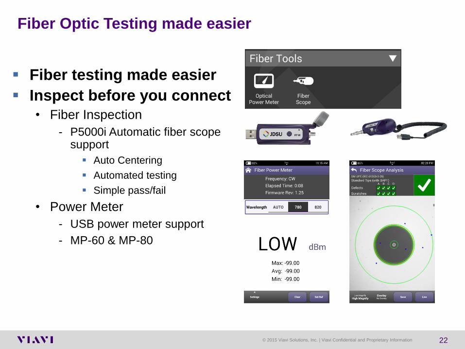
Fiber Optic Testing made easier
Fiber testing made easier
Inspect before you connect
• Fiber Inspection
- P5000i Automatic fiber scope support
Auto Centering
Automated testing
Simple pass/fail
• Power Meter
- USB power meter support
- MP-60 & MP-80

23 23
RF Testing

© 2015 Viavi Solutions, Inc. | Viavi Confidential and Proprietary Information 24
Incorrect Levels
Low Video Levels
Produces noise in
the picture
• High Video Levels
Produces distortion in the
picture

© 2015 Viavi Solutions, Inc. | Viavi Confidential and Proprietary Information 25
Low Digital levels
Causes Digital signal to
Degrade.
This causes Tiling and Loss
of high Speed internet
access.

© 2015 Viavi Solutions, Inc. | Viavi Confidential and Proprietary Information 26
Digital vs. Analog
Power on digital carriers is spread across the channel.
Almost all power on an analog carrier is concentrated at the video carrier frequency.
Analog Video
Spectrum
Digital Video/Cable
Modem Spectrum
Channel Power Channel Power

© 2015 Viavi Solutions, Inc. | Viavi Confidential and Proprietary Information 27
Digital Average Power Level Measurements
Digital Average Power Measurements and Measurement Bandwidth
The spectrum analyzer view is an excellent tool to see discreet RF-carriers. ▫ Caution is needed when viewing digital
modulated signals (haystack). The signal’s level measurement is derived from the selected measurement bandwidth (resolution bandwidth). At an RBW of 300 kHz, a 64QAM - 6 MHz wide digital signal reads in the spectrum analyzer trace 3 dB too low.
The Average Power principle takes small slices from the integrated RF-energy, summing them together to one total power reading in the LEVEL-mode. Analog and digital (broadcast) QAM signal.
The recommended delta in level should be 6
to 10 dB.

© 2015 Viavi Solutions, Inc. | Viavi Confidential and Proprietary Information 28
Frequency +2.5 MHz -2.5 MHz
IF Measurement
Bandwidth = 280
kHz
+/- 140 kHz
0
Digital carrier under test
(6 MHz BW)
Non measured area based
on 280 kHz step size within
6 MHz total Bandwidth
Summing slices of the total integrated energy
Measuring the Digital “Haystack”

© 2015 Viavi Solutions, Inc. | Viavi Confidential and Proprietary Information 29
280 kHz
Bandwidth power
5 MHz
Bandwidth power
Measuring the Digital “Haystack”
Measuring the Peak Level
of the Digital Haystack
Measuring the Average
Level of the Digital
Haystack

© 2015 Viavi Solutions, Inc. | Viavi Confidential and Proprietary Information 30
Measuring Upstream Carrier Amplitudes A
mplit
ude
3.2 MHz wide 6.4 MHz wide 1.6 MHz wide CW
1 Hz wide
Test CW Signal
These three DOCSIS® carriers will NOT have the same peak
amplitude when hitting the input port of a CMTS at 0 dBmV “constant
power per carrier” and then measured with a typical spectrum analyzer
or signal level meter.

© 2015 Viavi Solutions, Inc. | Viavi Confidential and Proprietary Information 31
Digital TV Waterfall Graph
Picture Quality Vs. Impairments
Increasing Impairments ==>
Pic
ture
Qu
ality
==
>
Digital
Analog
Good
Much Better Still Great
Beginning to get
Customer
Complaints
Customer
Rebellion
Good
Until it
Crashes

© 2015 Viavi Solutions, Inc. | Viavi Confidential and Proprietary Information 32
C/N vs. BER vs. MER
No FEC

© 2015 Viavi Solutions, Inc. | Viavi Confidential and Proprietary Information 33
FEC causes Cliff Effect
A small variation
in MER (+/- 1 dB)
will cause a large
variation in BER
measurement.
Using BER for
trouble-shooting
and fault location
is not repeatable
and very
inaccurate.
1.10-1
1.10-9
4.10-4
2 23.5
40
4QAM 16QAM 64QAM 256QAM
MER
BER

© 2015 Viavi Solutions, Inc. | Viavi Confidential and Proprietary Information 34
BER Example
A 256QAM channel transmits at a symbol rate of
5M symbols per second
Bit rate = 8 bits per symbol X 5M symbol per
second =40M bits per second
Error Incident = Bit rate X BER = Errors Per
Second
BER Error Frequency Error Incident
10-12 1 in 1 Trillion bits 25000 secs between errs (6.94 hrs)
10-11 1 in 100 Billion bits 2500 secs between errs (41.67 mins)
10-10 1 in 10 Billion bits 250 secs between errs (4.167 mins) 10-9 1 in 1 Billion bits 25 seconds between errors
10-8 1 in 100 Million bits 2.5 seconds between errors 10-7 1 in 10 Million bits 4 errors per second 10-6 1 in 1 Million bits 40 errors per second
10-5 1 in 100 Thousand bits 400 errors per second
10-4 1 in 10 Thousand Bits 4000 errors per second
10-3 1 in 1 Thousand bits 40000 errors per second

© 2015 Viavi Solutions, Inc. | Viavi Confidential and Proprietary Information 35
Effects of Noise and Interference
Noise and Interference moves the carrier away from its ideal
location causing a spreading of the cluster of dots.
Ideal
Locations

© 2015 Viavi Solutions, Inc. | Viavi Confidential and Proprietary Information 36
Modulation Error Ratio (MER)
Analogous to S/N
A measure of how symbols (I vs. Q) are actually
placed, compared to ideal placement
MER(dB) = 20 x log RMS error magnitude
average symbol magnitude
Good MER
– 64 QAM: 28 dB MER
– 256 QAM: 32 dB MER
RMS error magnitude
Average symbol
magnitude

© 2015 Viavi Solutions, Inc. | Viavi Confidential and Proprietary Information 37
Vector Sum of I and Q Channels
Combining 2 carriers 90° of out of phase results in a carrier with
amplitude and phase modulation
4 Levels
of I
Channel
+ =
00
00
01 10 11
01
10
11
4 Levels
of Q
Channel
..10 11.. Data Stream
..10 11..
16 QAM
4 Levels of Q
4 L
eve
ls o
f I

© 2015 Viavi Solutions, Inc. | Viavi Confidential and Proprietary Information 38
Typical Constellations
I
Q
Decision
Boundary
16 QAM
64 QAM 256 QAM
16 QAM
• 16 combinations of
amplitudes and
phases

© 2015 Viavi Solutions, Inc. | Viavi Confidential and Proprietary Information 39
Phase Noise
Display appears to rotate at the extremes
HE down/up converters can cause phase noise
Random phase errors cause decreased
transmission margin
Caused by transmitter symbol clock jitter
Bad LO in meter can cause phase noise
Constellation
Constellation with Phase Noise Zoomed Constellation with Phase Noise
Rotation Rotation
© 2015 Viavi Solutions, Inc. | Viavi Confidential and Proprietary Information 40
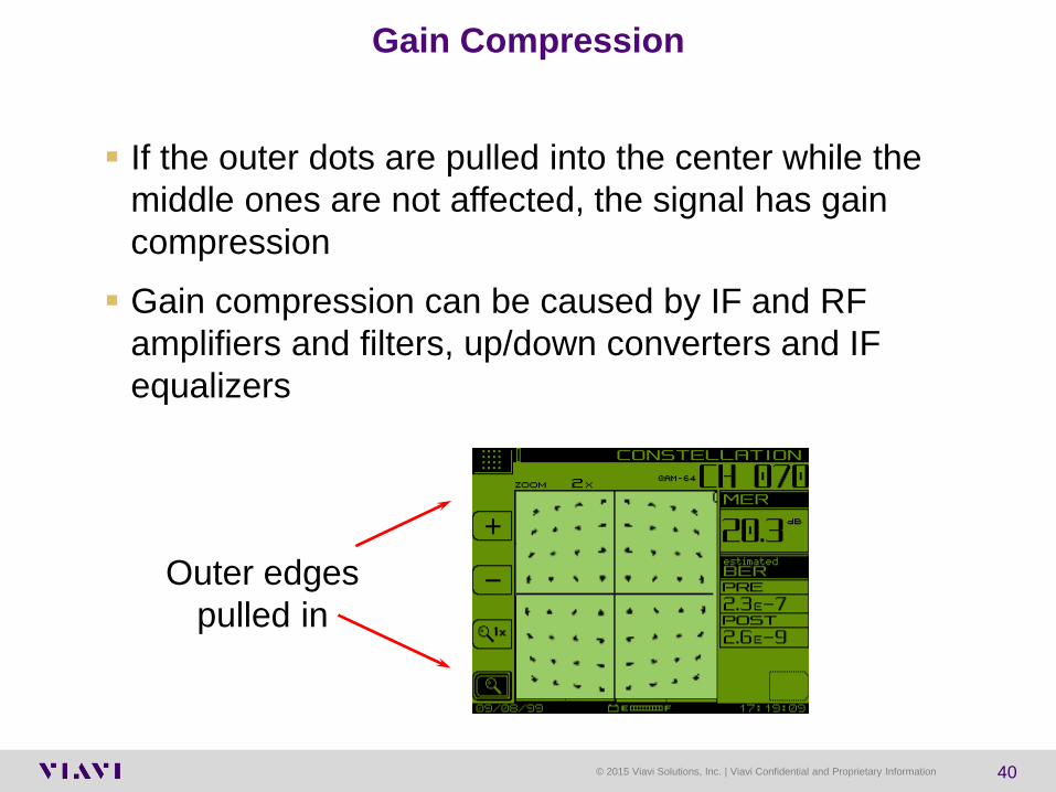
Gain Compression
If the outer dots are pulled into the center while the
middle ones are not affected, the signal has gain
compression
Gain compression can be caused by IF and RF
amplifiers and filters, up/down converters and IF
equalizers
Outer edges
pulled in

© 2015 Viavi Solutions, Inc. | Viavi Confidential and Proprietary Information 41
Coherent Interference
If the accumulation looks like a “donut”, the problem
is coherent interference
– CTB, CSO, Off-Air Carriers (ingress)
Sometimes only a couple dots will be misplaced
– This is usually laser clipping or sweep interference
Circular
“donuts”

© 2015 Viavi Solutions, Inc. | Viavi Confidential and Proprietary Information 42
Dots are spread
out showing
error
System Noise
A constellation displaying significant noise
Dots are spread out indicating high noise and most likely
significant errors
– An error occurs when a dot is plotted across a boundary and is
placed in the wrong location
Meter will not lock if too much noise present

© 2015 Viavi Solutions, Inc. | Viavi Confidential and Proprietary Information 43
Digital – more than just dB’s
MER and Pre and Post BER measurements are
key to insuring Digital Quality

© 2015 Viavi Solutions, Inc. | Viavi Confidential and Proprietary Information 44
High Frequency QAMs Have Margin Issues

© 2015 Viavi Solutions, Inc. | Viavi Confidential and Proprietary Information 45
Expected MER & BER Results

46 46
HFC Network

© 2015 Viavi Solutions, Inc. | Viavi Confidential and Proprietary Information 47
WHY SWEEP?
CATV amplifiers have a trade-off between noise and distortion
performance
Tightly controlling frequency response provides the best
compromise between noise and distortion.

© 2015 Viavi Solutions, Inc. | Viavi Confidential and Proprietary Information 48
Sweep vs. Signal Level Meter Measurements
References: Sweep systems allow a reference to be stored eliminating the
effect of headend level error or headend level drift.
Sweep Segments: Stealth makes it possible to divide the HFC plant into
network sections and test its performance against individual specifications.
Non-Invasive: Sweep systems can measure in unused frequencies. This
is most important during construction and system overbuilding.
BEST Solution to align: Sweep systems are more accurate and faster.

© 2015 Viavi Solutions, Inc. | Viavi Confidential and Proprietary Information 49
What faults cause CATV signals to fail ?
(80-90% of the time, the same faults…)
Success rate of finding and fixing the following problems using:
▫ Signal Levels
▫ TILT
▫ Gain / Loss
▫ Suck-outs (notches)
▫ C/N
▫ HUM
▫ CTB/CSO Intermodulation
▫ CPD - Forward and Reverse
▫ Reverse Ingress
▫ BER / MER
▫ Reflections / Standing waves
Source: Research 11/97-2/98 Market survey with 200 US and European CATV operators
0 50 100
121% Reverse Ingress
23% Signal Level Meters
11% BER Digital Analyzers
72% Forward & Reverse Sweep
5% Spectrum Analyzers
7% Visual TV-picture inspection

© 2015 Viavi Solutions, Inc. | Viavi Confidential and Proprietary Information 50
Sweep Reponse of a Splitter
RF
IN
RF
OUT
INPUT
OUTPUT
© 2015 Viavi Solutions, Inc. | Viavi Confidential and Proprietary Information 51
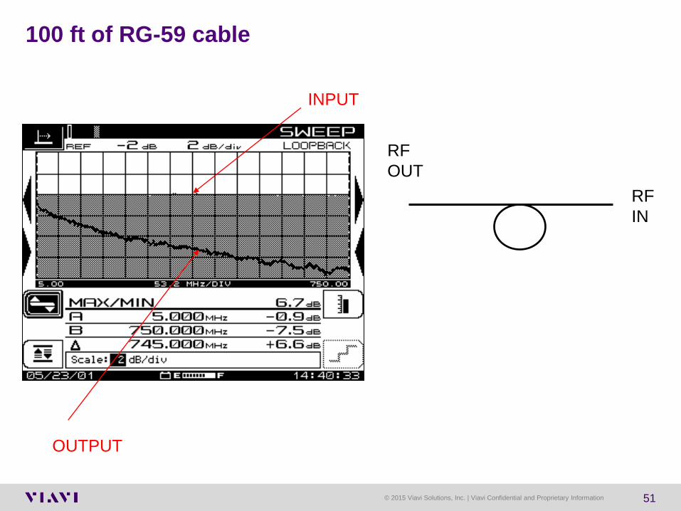
100 ft of RG-59 cable
RF
IN
RF
OUT
INPUT
OUTPUT

© 2015 Viavi Solutions, Inc. | Viavi Confidential and Proprietary Information 52
Forward Path Unity Gain
OUT +36 dBmV
OUT +36 dBmV
OUT +36 dBmV
OUT +36 dBmV
AMP # 1 AMP # 2 AMP # 3
AMP # 4
IN +14 dBmV
IN +11 dBmV
IN +10 dBmV
2 dB
8 dB 22 dB @ 750 MHz 23 dB @ 750 MHz
18 d
B @
750 M
Hz

© 2015 Viavi Solutions, Inc. | Viavi Confidential and Proprietary Information 53
Return Path Unity Gain
AMP # 1 AMP # 2 AMP # 3
AMP # 4
OUT +30 dBmV
2 dB
8 dB
IN +20 dBmV
IN +20 dBmV
IN +20 dBmV
OUT +24 dBmV
OUT +26 dBmV
IN +20 dBmV
4 dB @ 40 MHz 4 dB @ 40 MHz
2 d
B @
40 M
Hz

© 2015 Viavi Solutions, Inc. | Viavi Confidential and Proprietary Information 54
A Sweep Finds Problems That Signal Level Measurements Miss
Standing Waves
Roll off at band edges
Misalignment

© 2015 Viavi Solutions, Inc. | Viavi Confidential and Proprietary Information 55
Balancing Amplifiers Balancing amplifiers using tilt
No Termination
Lose Face Plate, or crack cable shield
Node Reference Signal Sweep response
with a Resonant Frequency
Absorption
Sweep response
with standing waves

© 2015 Viavi Solutions, Inc. | Viavi Confidential and Proprietary Information 56
Typical Forward Sweep Response
Fiber Node Line Extender End of Line Tap

© 2015 Viavi Solutions, Inc. | Viavi Confidential and Proprietary Information 57
Sweep Verifies Construction Quality
• Sweep can find craftsmanship or component
problems that aren’t revealed with other tests
• Damaged cable
• Poor connectorization
• Amplifier RF response throughout its frequency range
• Gain
• Slope
• Loose seizure screws, module hardware, …….

58 58
Customer Netoworks

© 2015 Viavi Solutions, Inc. | Viavi Confidential and Proprietary Information 59
TAP
Drop Cable
House
TV
GROUND
BLOCK
CABLE MODEM
TV
2-Way Splitter
Splitter 3-Way
STB
Courtesy of JDSU
55.25 MHz 745.25 MHz
Low end roll off High end roll off
Resonant Frequency
absorption
Validate tap performance
AMP
1
x
x
x
x
x
x
AMP
2
Min analog Video
Ch 2-78 15.6dBmv
Min QAM
Ch 79-158 8.75 dBmV
1000 MHz
system
Tilt and power levels change from
TAP to TAP
Mechanical issues cause customer
problems
Power Levels
must be
maintained for
high frequency
losses

© 2015 Viavi Solutions, Inc. | Viavi Confidential and Proprietary Information 60
If systems were flat!
Tight limit bands would be a simple solution
Ideal Case
-20
-15
-10
-5
0
5
10
15
20
50 150
250
350
450
550
650
750
850
950
Freq (MHz)
Le
ve
l (d
Bm
V)
Ideal TV
Typ
IdealHLimit
IdealLowLimit
Digital Tiers Analog tiers

© 2015 Viavi Solutions, Inc. | Viavi Confidential and Proprietary Information 61
In real systems – tilt happens!
Tilt Affects Limits
-20
-15
-10
-5
0
5
10
15
20
50 150
250
350
450
550
650
750
850
950
Freq (MHz)
Level
(dB
mV
)
Ideal TV
Typ
PosTilt
NegTilt
IdealHLimit
IdealLowLimit

© 2015 Viavi Solutions, Inc. | Viavi Confidential and Proprietary Information 62
Miniscan and Tilt Views Quick View of Channels with LIMITS
Mix all channels,
analog and digital
Tilt enhances view for
quick check of
alignment
© 2015 Viavi Solutions, Inc. | Viavi Confidential and Proprietary Information 63
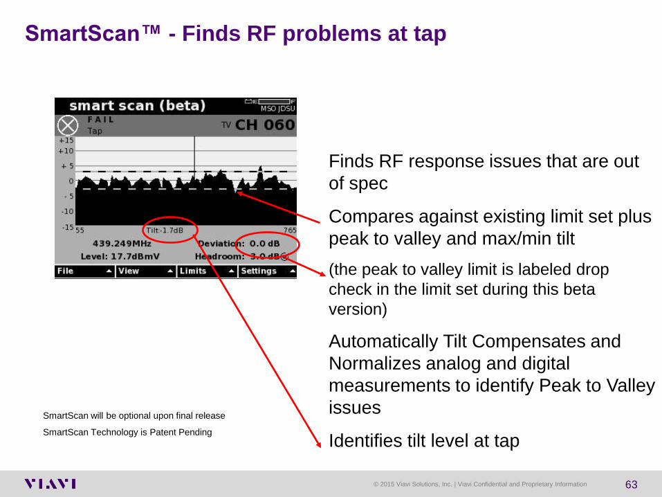
SmartScan™ - Finds RF problems at tap
Finds RF response issues that are out
of spec
Compares against existing limit set plus
peak to valley and max/min tilt
(the peak to valley limit is labeled drop
check in the limit set during this beta
version)
Automatically Tilt Compensates and
Normalizes analog and digital
measurements to identify Peak to Valley
issues
Identifies tilt level at tap
SmartScan will be optional upon final release
SmartScan Technology is Patent Pending

© 2015 Viavi Solutions, Inc. | Viavi Confidential and Proprietary Information 64
DSAM 3.0 Bonded Carrier testing – coming soon
Keeping it simple for the technicians
Validate overall performance
Identifying individual US/DS channel
issues

© 2015 Viavi Solutions, Inc. | Viavi Confidential and Proprietary Information 65
DOCSIS, Video and Ingress Scan made
easier
Validate faster & more efficiently
▫ Ultra-Fast testing of 136 channels in <30
seconds (including MER, BER, Level)
Ingress detection made easier
▫ 2nd port 4-110 MHz simultaneous ingress scan
with connection detection™
▫ Background scanning for Ingress in LTE bands
or other off-air bands
Guided problem resolution
▫ Session Expert directs to suggested next
actions based on measurements
▫ Easily compare between the demarcation
points
Complete RF and DOCSIS service testing made easier

© 2015 Viavi Solutions, Inc. | Viavi Confidential and Proprietary Information 66
Troubleshooting between
demarcation points made easier
Test Location aware helps guide
technicians to problems
Session awareness uses data at the
demarcation points to suggest next
actions
Side by side comparison helps
technicians prove they have fixed
the problems
Complete RF and DOCSIS service testing made easier

© 2015 Viavi Solutions, Inc. | Viavi Confidential and Proprietary Information 67
QAM – testing made easier & faster
▫ Troubleshoot faster & more efficiently
Ultra-Fast testing of 136 channels in <30 seconds
(MER, BER, Level)
Ingress detection
▫ Integrated in-channel Ingress Under the Carrier
detects interferers
Easily find intermittent problems
▫ Concurrent measurements
▫ No need to guess which tool to use
▫ ANY technician can identify problems
▫ DQI over
▫ MER, BER over time
QAM testing made easier

© 2015 Viavi Solutions, Inc. | Viavi Confidential and Proprietary Information 68
DOCSIS – testing made easier & faster
▫ Test and Bond up to 32 carriers simultaneously
▫ Upstream testing and bonding of up to 8 carriers
Gigabit DOCSIS service testing
▫ Validate your premium service offerings with 32x8
Throughput and Packet Quality
Identify and resolve Physical Layer issues
▫ Simultaneous testing of Phy layer and Service
layer identifies carrier and noise problems
▫ DQI over time
▫ MER, BER over time
▫ LTE & Off Air Ingress
DOCSIS troubleshooting made easier

69 69
Ingress and Egress

© 2015 Viavi Solutions, Inc. | Viavi Confidential and Proprietary Information 70
What Type of Problem: Common Impairments
Ingress ▫ Still the most common
▫ Use return path monitoring system to
know when to chase
Common Path Distortion ▫ Old news in analog DS plant
▫ New look in all-digital plant
Impulse Noise ▫ Impulse noise troublesome for CMTS
▫ RFI detector for power-line noise

© 2015 Viavi Solutions, Inc. | Viavi Confidential and Proprietary Information 71
Mobile Networks are Strained
More Cells Required
• For example: a 700 MHz LTE network with 10
MHz, provides 15 Mbps of sector throughput .
• In the US alone there could be on average
1000 subscribers site, or 333 per sector.
• Each subscriber will be sharing 15 Mbps!
Average Subscribers per Cell Site (US)
Too many users are simultaneously
using the same capacity
• LTE/4G build out requires an order of
magnitude more cell sites.
.
More Cells & Antennas Required to Reduce Subscriber Density
Macrocell Coverage
Microcell Coverage

© 2015 Viavi Solutions, Inc. | Viavi Confidential and Proprietary Information 72
Compact Radio Heads
▫ Affordably enable an order of
magnitude more antennas
▫ Lower power, closer to subscribers
▫ Reduce deployment costs, improve
user experience
Massive Antenna Expansion Required
Macrocell expansion alone is not practical
– An Order of Magnitude Increase Needed
– Costly
– Energy hungry
– Unsightly: Not In My Backyard
New Remote Radio Backhaul Strategies are Required
Source: Alcatel-Lucent

© 2015 Viavi Solutions, Inc. | Viavi Confidential and Proprietary Information 73
LTE Uplink and frequency ranges
Frequency range used for LTE Uplinks

© 2015 Viavi Solutions, Inc. | Viavi Confidential and Proprietary Information 74
LTE interference to cell service providers and to
cable customers
▫ Fear of FCC fines/regulation
▫ Potential loss of bandwidth
▫ Churn from dissatisfied customers (strong competitive
environment)
Competition – optimum reliability/performance
▫ Leakage in UHF band tightly linked to
plant integrity
▫ Signals higher due to system tilt
▫ Leak characteristics match test wavelength
QAM Egress Option Market Drivers

© 2015 Viavi Solutions, Inc. | Viavi Confidential and Proprietary Information 75
Optimize signal levels to networked devices
Use components with good shielding integrity
Follow proper procedures for good craftsmanship and
tightening
Avoid locating CPE devices close to uplink devices
▫ Femtocells, MiFi wireless repeaters
▫ Power-down these devices as troubleshooting step
Tech, put cell phone in “airplane” mode while
testing/troubleshooting
▫ Transmit power ~2.2V/m at 3 feet (worst case)
3V/m is target RF immunity of CPE
(UHF Signal Leakage and Ingress, Hranac, R., Segura, N., 2013)
Best Practices (considering LTE presence)
© 2015 Viavi Solutions, Inc. | Viavi Confidential and Proprietary Information 76
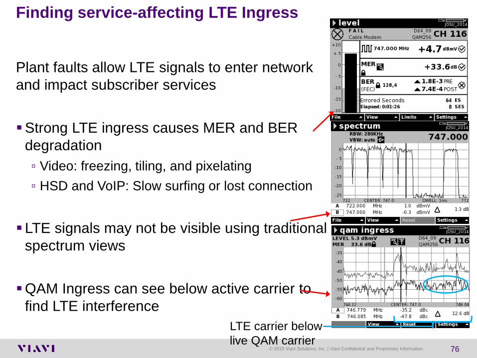
Plant faults allow LTE signals to enter network
and impact subscriber services
Strong LTE ingress causes MER and BER
degradation
▫ Video: freezing, tiling, and pixelating
▫ HSD and VoIP: Slow surfing or lost connection
LTE signals may not be visible using traditional
spectrum views
QAM Ingress can see below active carrier to
find LTE interference
Finding service-affecting LTE Ingress
LTE carrier below
live QAM carrier

© 2015 Viavi Solutions, Inc. | Viavi Confidential and Proprietary Information 77
QAM Egress Test Option – Screens
• Uses active channel plan to identify QAM
channels in spectrum
• Blue regions mark QAM signal boundaries
in active channel plan when QAM signature
is not currently detected
• When blue channel highlights turn RED,
QAM signature detected based on selected
threshold
• Center frequency
• QAM signature detection beep
(on/off)
• Active channel plan overlay (on/off)
• Adjustable QAM detection sensitivity
(Low, Med, High)
• The mode allows users to adjust :

© 2015 Viavi Solutions, Inc. | Viavi Confidential and Proprietary Information 78
What Causes Signal Leakage & Ingress?
Most common source of leakage is within the home wiring
(approximately 75%) and drop cable (approximately 20%).
There’s a lot of homes that still have the original wiring from 20-
30 years ago!
Inferior quality coaxial cable, passives, connectors
Poor installation of splices and connectors - water and weather
can result in pulled out, loose or corroded connectors
Illegal connections to neighbor’s cable
Some of the older TV sets with poor tuner shielding can produce
leakage and ingress problems

© 2015 Viavi Solutions, Inc. | Viavi Confidential and Proprietary Information 79
RF ingress — The 5-42 MHz reverse spectrum is shared
with numerous over-the-air users.
Signals in the over-the-air environment include high power
shortwave broadcasts, amateur radio, citizens band,
government, and other two-way radio communications.
Reverse Path Impairments - Ingress
© 2015 Viavi Solutions, Inc. | Viavi Confidential and Proprietary Information 80
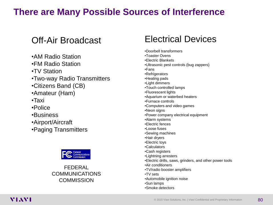
Electrical Devices
•Doorbell transformers
•Toaster Ovens
•Electric Blankets
•Ultrasonic pest controls (bug zappers)
•Fans
•Refrigerators
•Heating pads
•Light dimmers
•Touch controlled lamps
•Fluorescent lights
•Aquarium or waterbed heaters
•Furnace controls
•Computers and video games
•Neon signs
•Power company electrical equipment
•Alarm systems
•Electric fences
•Loose fuses
•Sewing machines
•Hair dryers
•Electric toys
•Calculators
•Cash registers
•Lightning arresters
•Electric drills, saws, grinders, and other power tools
•Air conditioners
•TV/radio booster amplifiers
•TV sets
•Automobile ignition noise
•Sun lamps
•Smoke detectors
There are Many Possible Sources of Interference
Off-Air Broadcast
•AM Radio Station
•FM Radio Station
•TV Station
•Two-way Radio Transmitters
•Citizens Band (CB)
•Amateur (Ham)
•Taxi
•Police
•Business
•Airport/Aircraft
•Paging Transmitters
FEDERAL
COMMUNICATIONS
COMMISSION

© 2015 Viavi Solutions, Inc. | Viavi Confidential and Proprietary Information 81
Headend Headend
Reverse System
“Noise Funneling”
Ingress from seven
amplifiers ends up
at the headend.
Forward Signals
Noise
Noise
Downstream and Upstream
Noise Additions

© 2015 Viavi Solutions, Inc. | Viavi Confidential and Proprietary Information 82
NODE
Tracking Down Ingress – Divide and Conquer
View local spectrum on each return path
test point of node to determine which leg
has the source of ingress
Use divide and conquer technique to
identify and repair source of ingress

© 2015 Viavi Solutions, Inc. | Viavi Confidential and Proprietary Information 83
Typical Problem Areas
Taps ▫ Most ingress comes from houses off of with low value taps of
approximately 17 dB or less
Home Wiring ▫ Drop Cable, splitters & F Connectors are approximately ~95% of
Problem
Amplifiers, hard line cable and the rest of the
system are a small percentage of the problem if a
proper leakage maintenance program is performed
low value taps low value taps

© 2015 Viavi Solutions, Inc. | Viavi Confidential and Proprietary Information 84
Return Path
Taps - Probe the Seizure Screws for Ingress & CPD
If the problem is at the FWD Input and not the FWD
Output, then the problem is likely from one of the
drops If the problem is at
the FWD Output of
tap, continue on
towards end of line Forward Path

© 2015 Viavi Solutions, Inc. | Viavi Confidential and Proprietary Information 85
4 Port Tap
Taps are made up of a Directional Coupler and Splitters
Disconnect one drop at a
time to determine the point
of entry
If the problem is at the Forward Input and not the Forward Output,
then the problem is from one of the drops
Forward Path Return Path

© 2015 Viavi Solutions, Inc. | Viavi Confidential and Proprietary Information 86
Common problems in HFC Networks
© 2015 Viavi Solutions, Inc. | Viavi Confidential and Proprietary Information 87
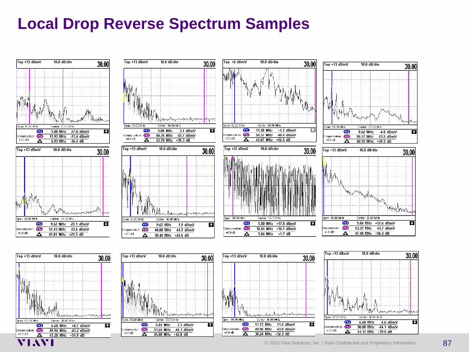
Local Drop Reverse Spectrum Samples

© 2015 Viavi Solutions, Inc. | Viavi Confidential and Proprietary Information 88
The subscriber drop remains the weakest link in the cable network
Seven out of ten service calls are generated by problems at the drop
Ingress caused in the home wreaks havoc on the reverse path ▫ Must be found in the home before connecting to network when
possible ▫ Must be monitored continuously and eliminated quickly
Replacing all home wiring is economically unacceptable,
testing is required to find faults and bring the home wiring up to standards necessary for new services.
In-Home Wiring Is A Potentially Large Stumbling Block

© 2015 Viavi Solutions, Inc. | Viavi Confidential and Proprietary Information 89
Electrical Impulse Noise from One House
-60
-50
-40
-30
-20
-10
0
10
20
30
40
Center: 25.000 MHzSpan: 40.000 MHz
RBW: 300 KHz VBW: 100 KHz Dwell: 400 µS
In-Band Power 10.393 dBmV
-60
-50
-40
-30
-20
-10
0
10
20
30
40
Center: 25.000 MHzSpan: 40.000 MHz
RBW: 300 KHz VBW: 100 KHz Dwell: 400 µS
In-Band Power 8.632 dBmV
•Reverse Spectrum shot at customer's drop

© 2015 Viavi Solutions, Inc. | Viavi Confidential and Proprietary Information 90
eMTA-CABLE MODEM
7 dB TAP
Drop Cable
High Pass
Filter GROUND
BLOCK
3-Way
Splitter
DIGITAL SET-TOP
House
2-Way
Amplifier
Testing the Home for Ingress Contribution
VoIP
OLDER TV SET
Return
Equalizer
ONLINE GAMING
WIRELESS LAPTOP
COMPUTOR
ETHERNET
Disconnect drop from tap
and check for ingress
coming from customer’s
home wiring
INGRESS SPECTRUM MEASUREMENTS
If ingress is detected, scan
spectrum at ground block
for ingress

© 2015 Viavi Solutions, Inc. | Viavi Confidential and Proprietary Information 91
Testing and Troubleshooting House Wiring
Homes
Measuring signal levels throughout the spectrum is a
standard requirement for analog cable TV services.
Leakage detection finds wiring damage or poor
craftsmanship that can result in ingress points, which
impacts upstream and downstream signals.
Spectrum analysis of the reverse spectrum can
identify ingress.
Frequency response checks ensure that there are no
bandwidth problems.
Locating faults for repair can help eliminate reflections
which can seriously impact digital signals.

© 2015 Viavi Solutions, Inc. | Viavi Confidential and Proprietary Information 92
Common Problems Typically Identified in the Drop
Kinked or damaged cable (including cracked cable, which
causes a reflection and ingress)
Use of staples that perforate or compress coaxial cable
resulting in impedance mismatches
Cable-ready TVs and VCRs connected directly to the drop
(Return loss on most cable-ready devices is poor)
Older splitters and amplifiers may not be rated for 750MHz,
860MHz or 1GHz
Some traps and filters have been found to have poor return loss
in the upstream, especially those used for data-only service

© 2015 Viavi Solutions, Inc. | Viavi Confidential and Proprietary Information 93
As operators add more and more QAM carriers to the downstream,
Common Path Distortion beats can show up in the return spectrum as
distinct “haystacks” in the noise floor which are spaced in 6 MHz intervals!
“QAM like haystacks” are 6
MHz wide and spaced in 6
MHz intervals!
Common Path Distortion (CPD)
“QAM CPD beats”
30 MHz
36 MHz
42 MHz
“Analog Video beats” can still show up
at “typical CPD frequencies” which are
spaced in 6 MHz intervals.
“QAM Generated” Common Path Distortion Beats

© 2015 Viavi Solutions, Inc. | Viavi Confidential and Proprietary Information 94
Ingress - Off-air Broadcast Radio Carrier
Off-air public broadcast radio
carrier under the DOCSIS®
16QAM carrier
Coherent Interference If the constellation looks like it has “donut
shapes” in it, the problem is likely to be some
form of coherent interference.
Often caused by off-air ingress such as
citizens band radio, shortwave radio, or
other broadcast radio sources.

© 2015 Viavi Solutions, Inc. | Viavi Confidential and Proprietary Information 95
Ingress - CB Radio
CB Radio

© 2015 Viavi Solutions, Inc. | Viavi Confidential and Proprietary Information 96
Wide Band Impulse Noise and Laser Clipping
Impulse noise goes past
diplex roll-off at 42 MHz

© 2015 Viavi Solutions, Inc. | Viavi Confidential and Proprietary Information 97
Wideband Impulse Noise = Code Word Errors!
Diplex roll-off
at 42 MHz

© 2015 Viavi Solutions, Inc. | Viavi Confidential and Proprietary Information 98
Abnormal rise in
the noise floor
above diplex
roll-off
frequency
Too Much Optical Power into Optical Receiver
Too much optical power (light level) into the input of a return
optical receiver can cause an abnormal rise in the noise floor
above the diplex filter roll-off frequencies.
42 MHz diplex filter
roll-off frequency

© 2015 Viavi Solutions, Inc. | Viavi Confidential and Proprietary Information 99
After adding 2 dB of
optical attenuation at
the input of the
optical receiver, the
noise floor above
diplex roll-off
frequency now looks
normal.
2 dB of additional optical attenuation was added to the return
input of the optical receiver and resulted in a “flatter noise floor”
above the diplex filter roll-off frequencies.
42 MHz diplex filter
roll-off frequency
Too Much Optical Power into Optical Receiver

100 100
Linear Distortions

© 2015 Viavi Solutions, Inc. | Viavi Confidential and Proprietary Information 101
Common Linear Distortion Impairment Types
Micro-reflections
Common Causes
– Damaged/missing
terminators
– Loose seizure screws
– Water-filled taps
– Cheap/damaged splitters or
CPE
– Kinked/damaged cable
– Install Issues
Group Delay
Common Causes
– Operation too close to
diplex roll-off
– Defective diplex filters
– AC power coils/chokes
– Notch Filters (high-pass,
HSD-only, etc)
– Micro-reflections
In-channel Freq. Response
Common Causes
– Misalignment
– Impedance mismatches

© 2015 Viavi Solutions, Inc. | Viavi Confidential and Proprietary Information 102
Optical Link is Critical to Upstream Performance
RF level is too high at input of return laser ▫ Verify light level at input of return optical receiver
▫ Verify RF level at input of return laser
▫ Verify RF spectrum above diplex frequency at input of return laser
30 MHz 60 MHz
36 MHz 72 MHz
WebView v2.5 FFT View of the Upstream

© 2015 Viavi Solutions, Inc. | Viavi Confidential and Proprietary Information 103
Common Impairments: Laser Clipping
Caused by Overdriving Laser ▫ Low end ingress
▫ Improper laser setup
▫ Adding carriers without compensating
Very distinct constellation footprint ▫ Also see as junk above diplex in spectrum
▫ Optical receiver issues can look similar
Before/After:
Faulty Optical Receiver
Similar to Laser Clipping
Wide band impulse
noise above diplex
roll-off frequency

© 2015 Viavi Solutions, Inc. | Viavi Confidential and Proprietary Information 104
Diamond shaped clusters in
the constellation
PathTrak QAM Analyzer View – Group Delay & Micro-
reflections
Multiple cable modems with
different MER levels
Group Delay / Microreflections If the accumulation takes on a diamond shape, the problem is likely a group delay issue
Constellation may take on a diamond or square shape
Clarity of diamond shape will vary with percentage of packets affected
Microreflections are a common cause of group delay
Often caused by unterminated or improperly terminated lines or faulty CPE (cheap TV or VCR)
Group delay can also result from a carrier placed too close to the band edge of the diplex filter

© 2015 Viavi Solutions, Inc. | Viavi Confidential and Proprietary Information 105
Bad In-Band Response from a Single Modem
Move this marker and all of the displays will show the
corresponding measurements for each packet
© 2015 Viavi Solutions, Inc. | Viavi Confidential and Proprietary Information 106
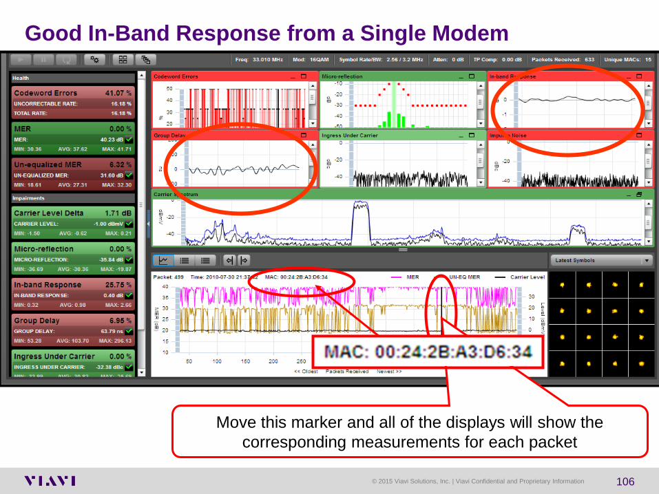
Good In-Band Response from a Single Modem
Move this marker and all of the displays will show the
corresponding measurements for each packet

© 2015 Viavi Solutions, Inc. | Viavi Confidential and Proprietary Information 107
Beware of Taps
Port 1 2thru8 not terminated Port 1 2thru8 terminated

© 2015 Viavi Solutions, Inc. | Viavi Confidential and Proprietary Information 108
Node Performance Summary - Node C012 on June 4th
Impulse Noise = Codeword Errors

© 2015 Viavi Solutions, Inc. | Viavi Confidential and Proprietary Information 109
Correlate: Automatically Separate Modems With
Statistically Similar Freq Responses Into Groups
▫ Their packets are passing through the same
impairment(s)
Localize: Plot Modem Groups on Google Map To
Allow Identification of Last Common Isolation Point
▫ Where to start field find and fix from
Pinpoint: Use Microreflection Data To Calculate
“Echo Cavity” distance
▫ Dispatch to fix, not to find
How Pre-Equalization Data Can Help Cable Operators Correlate, Localize, and Pinpoint Impairments Quickly – Right From Your Desk

© 2015 Viavi Solutions, Inc. | Viavi Confidential and Proprietary Information 110
How To Troubleshoot/Localize Linear Impairments
Reverse path
optical receiver
Forward path Laser Headend
Web-Based Server
Headend
RP Monitoring System
Internet
1. Start at first known-bad point, register meter on suspect carrier
1a. Check meter packets demod’d at headend on laptop
2. If bad go to next test point toward headend, check packets
3. Continue toward HE until packets are good
4. Once localized fix the issue (Bad tap in this example)
5. VERIFY FIX using customer CM and meter packets

© 2015 Viavi Solutions, Inc. | Viavi Confidential and Proprietary Information 111
Linear Distortions Tests
Forward Path
Return Path

© 2015 Viavi Solutions, Inc. | Viavi Confidential and Proprietary Information 112
Testing for Ingress on Forward Digital Carriers

© 2015 Viavi Solutions, Inc. | Viavi Confidential and Proprietary Information 113
Tools for Troubleshooting
▫ View 4MHz – 1GHz, in either 10 or 50 MHz spans, without
changing modes
▫ While viewing return spectrum; enable a Low Pass Filter Cuts out the higher frequency noise
Cleaner return path view; lower noise floor
▫ Increase Dwell time (1-25ms) per frequency scan Find intermittent impairments better/quicker
▫ Adjust resolution bandwidth (RBW) from 330KHz to 30KHz Shows more spectrum characteristics with smaller spectral slices
adding to the overall resolution
Users can now adjust the spectrum mode to better see
intermittent ingress, harmonics, and other channel
anomalies. They can also look over both the upstream and
downstream spectrums in one mode as well as isolate the
return path from the forward path, eliminating noise leaking
down into the return path.
*All HW versions

© 2015 Viavi Solutions, Inc. | Viavi Confidential and Proprietary Information 114
Qualifying Data over RF
VoIPCheck Save ▫ Save and Archive VoIPCheck results ▫ TPP file archiving and result viewing
Increased DOCSIS Throughput ▫ DOCSIS 1.1
1.5 MB/s US; 15 MB/s DS

115 115
Home Networks

© 2015 Viavi Solutions, Inc. | Viavi Confidential and Proprietary Information 116
Home Networking Technologies
Ethernet ▫ Runs on Cat-5 ▫ Less than 5% of Homes wired for Ethernet
MoCA™ Multimedia over Coax Alliance ▫ Runs on existing Coax
HPNAv3 Home Phone Network Alliance ▫ Runs on Coax OR over existing phone lines
HomePlug® A/V ▫ Runs over AC wiring
Proprietary over coax ▫ TV Net(Coaxsys)/HomeRan(TMT Networks)
Wireless 802.11 b/g/a/n/ac ▫ Range limited due to propagation through walls

© 2015 Viavi Solutions, Inc. | Viavi Confidential and Proprietary Information 117
Ethernet testing made easier
▫ Dual 1G Ethernet ports
▫ Ping
▫ HTTP/FTP transfer tests
▫ Web Browser test
▫ TrueSpeed (stand alone option)
Ethernet testing made easier
B I T B I T I T I T Optional

© 2015 Viavi Solutions, Inc. | Viavi Confidential and Proprietary Information 118
HomePlug 1.0 and HomePlug AV
“Products based on the HomePlug 1.0
and HomePlug AV specifications can
bridge an existing networking
technology (such as a wireless or
Ethernet network) and your home's
power lines. “
Network your TV
with HomePlug AV

© 2015 Viavi Solutions, Inc. | Viavi Confidential and Proprietary Information 119
Home Plug Interference
HomePlug uses 917 OFDM sub-
carriers. OFDM modulation allows co-
existence of several distinct data
carriers in the same wire.
“The number of whole-home DVR
installations is expected to grow at a
CAGR of over 100 percent from 2006
to 2008.”
-- In-Stat

© 2015 Viavi Solutions, Inc. | Viavi Confidential and Proprietary Information 120
HomePNA™ - Home Networking
Features
• Uses your existing coaxial wiring
• Perfect for transferring large multimedia files such as movies, music, and photos
• Uses existing coax cabling
• Supports speeds up to 144 Mpbs burst, 95 Mbps sustained
• Complies with the HPNA 3.1 over coax specification (ITU G.9954)
• Supports point-to-point and point-to-multipoint network configurations

© 2015 Viavi Solutions, Inc. | Viavi Confidential and Proprietary Information 121
HPNA Physical Network Topology
Node
Device
Node
Device
Telco
NID
Node
Device
Node
Device
Twisted Pair Star
Configuration3-Way
2-Way
3-Way
Node
Device
Node
Device
Node
DeviceTV
Node
Device
Node
Device
Splitter
JumpingSplitter
Jumping
WAN Entry Point
< 25 db loss
< 300 ft
Coax Network
Configuration

© 2015 Viavi Solutions, Inc. | Viavi Confidential and Proprietary Information 122
Wideband HomePNA™ Ingress in the Return Path
“The HomePNA™ Alliance develops triple-play home networking solutions for distributing
entertainment data over both existing coax cable and phone lines. “
6.4 MHz DOCSIS® Carrier
HPNA signal from a single home!

© 2015 Viavi Solutions, Inc. | Viavi Confidential and Proprietary Information 123
Wireless
20
.00m
.
30.0
0m
.
50
.00m
.
2/24 Mbps
11/54Mbps
802.11b / 802.11g
54 Mbps
36 Mbps
24Mbps
7.0
0m
.
10.0
0m
.
20
.00m
.
802.11a
164.0ft.
65.6ft.
98.4ft.
65.6ft.
32.8ft.
23.0ft.
5.5/36 Mbps

© 2015 Viavi Solutions, Inc. | Viavi Confidential and Proprietary Information 124
WiFi Uses - Subscriber Issue:
Can’t maintain good connection to wireless access point (AP) or Slow surfing speed ▫ Tech checks the following on the subscribers network
If Signal strength at location of interest is low – Move the AP ▫ Avoid large distances or obstructions that can weaken the WiFi signal
Brick/Concrete/Metal Walls, appliances, or furniture can absorb or deflect WiFi signals
▫ WiFi signals typically transmit at the same level in all directions so placing the AP in a more central location allows for the most coverage
Identify a less occupied channel and move the AP to that channel ▫ If many networks use the same WiFi Channel they will conflict and
cause slower surfing speeds on all networks on the same channel ▫ Try to use non-overlapping channels to prevent the most conflicts
In the 2.4GHz range only channels 1, 6, and 11 do not overlap Secure the WiFi network with Password protection
▫ Unsecure, or Open, networks leave the subscriber open for anyone to use the WiFi network which could mean unauthorized users are using too much of the network’s available bandwidth – causing WiFi speed to slow down to the subscriber
▫ Open networks are also potential security holes for hackers

© 2015 Viavi Solutions, Inc. | Viavi Confidential and Proprietary Information 125
Signal Strength and Coverage Problems
▫ Attenuation with distance and materials in the home
▫ 5GHz has shorter reach than 2.4 GHz
802.11 Interference Sources
▫ Co-Channel interference (forces your AP to share the channel)
▫ Adjacent Channel interference (looks like noise to your AP)
Non-802.11 Interference Sources
▫ Microwaves, AV transmitters, cordless phones, baby monitors, etc.
High Channel Utilization:
▫ The more AP’s in a channel the higher the potential utilization
▫ High utilization, low noise = high 802.11 traffic on the channel
▫ High utilization, high noise = potential non-802.11 interferer
802.11a/b/g devices in your network
▫ Slow a/b/g PHY rates occupy the channel longer than modern PHY rates for the same amount of information transfer
▫ Old security types (WEP) limit connection to lower 802.11 rates
Understanding real WiFi Throughput is critical to reliable install
▫ Physical and Link layer results provide indications of actual WiFi throughput performance, but…
▫ WiFi is adaptive. Actual performance is dependent on many environmental factors and under-the-hood design complexities
Typical Residential / SOHO WiFi Problems Addressed
Channel utilization & noise
analysis
Co / adjacent channel
occupancy visualization &
analysis
2.4 & 5 GHz Spectrum
Analyzer
SmartChannel Wizard
auto-detection &
recommendations
Whole-Home Site
Assessment and
throughput margin testing
Problem WiFi Advisor Solutions
RSSI, SNR, noise trending
and throughput testing
© 2015 Viavi Solutions, Inc. | Viavi Confidential and Proprietary Information 126
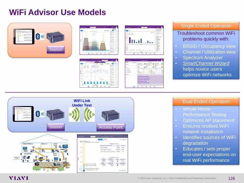
Troubleshoot common WiFi
problems quickly with:
• BSSID / Occupancy view
• Channel / Utilization view
• Spectrum Analyzer
• SmartChannel Wizard
helps novice users
optimize WiFi networks
Single Ended Operation
• Whole-Home
Performance Testing
• Optimizes AP placement
• Ensures resilient WiFi
network installation
• Identifies sources of WiFi
degradation
• Educates / sets proper
end-user expectations on
real WiFi performance
Dual Ended Operation
Station
Access Point Station
WiFi Link
Under Test
WiFi Advisor Use Models

© 2015 Viavi Solutions, Inc. | Viavi Confidential and Proprietary Information 127
WiFi testing made easier
Wi-Fi testing made easier
• Integrated 802.11 a/b/g/n for 2.4 and 5GHz testing
- SSID Scanning
- Signal Strength over Time
- Channel clearing
- (future) External option
WiFi Advisor interface for TrueMargin, 802.11ac 3x3 and Site Assessment
• WiFi Access Point - Test customer CPE for
connectivity and provisioning
B I T B I T B I T
I T

© 2015 Viavi Solutions, Inc. | Viavi Confidential and Proprietary Information 128
Wireless Site Survey Screen
DSAM’s WiFi
Adapter MAC
List of WiFi
networks
detected
Highlighted
Network’s
Information
Scroll bar indicated that more networks than can be
displayed are available for viewing

© 2015 Viavi Solutions, Inc. | Viavi Confidential and Proprietary Information 129
What is MoCA?
Stands for: Multimedia over Coax Alliance
Main applications:
▫ Whole Home DVR
▫ Connect IP enabled devices
MoCA is very robust
▫ 50-60dB of loss
Excess Attenuation is the biggest killer of
MoCA
Several Operators estimate that
MoCA services will first be available
end of this year or early next year

© 2015 Viavi Solutions, Inc. | Viavi Confidential and Proprietary Information 130
Point of Entry (POE) Filter
A MoCA filter (aka: POE filter) performs two jobs.
▫ First it removes the MoCA signal from entering a neighbors house
Stops MoCA signal from leaving the home
▫ Second it gives MoCA a point of reflection for the signal
MoCA relies on the signals to “bounce” output to output on splitters
POE
MoCA/POE
Filter
130

© 2015 Viavi Solutions, Inc. | Viavi Confidential and Proprietary Information 131
MoCA Just Evolved to V2.0
5 MHz 55 MHz 1 GHz 1.7 GHz
Upstream
Range
Downstream
Range
MoCA 1.x
Range
850 – 1525 MHz 55 – 1000 MHz 5 – 45
MHz
MoCA 1.x Frequency View
5 MHz 55 MHz 1 GHz 1.7 GHz
Upstream
Range
Downstream
Range
MoCA 2.0
Range
500 – 1650 MHz 55 – 1000 MHz 5 – 45
MHz
MoCA 2.0 Frequency View
850MHz and
1.525GHz
50MHz wide
‘channels’
Speeds up to
175Mbps
500MHz and
1.65GHz
100MHz wide
‘channels’
Speeds above
400Mbps
DIFFERENT
HARDWARE

© 2015 Viavi Solutions, Inc. | Viavi Confidential and Proprietary Information 132
ID & Locate
with…
Potential In-Home Coax Network Impairment:
1 IW-1000 Bad Splitters
2 IW-1000 Too Many Splitters
3 IW-1000 Hidden Splitters
4 MSQ or Visual High Frequency Roll off of Splitter (rated @ or below 900MHz)
5 Visual Inspection Poor Connector (Wrong type/Hex Crimp)
6 IW-1000 Impedance Mismatches
7 IW-1000 Loose Connection (Ingress)
8 Visual Inspection Loose Connection (Intermittent Signal)
9 IW-1000 Lossy Cable
10 IW-1000 Broken Coax Shield (ingress)
11 IW-1000 Wrong Coax Path
12 IW-1000 Bad Barrel (or wallplate)
13 IW-1000 Corroded Barrel
14 CPE Diagnostic Bad Box (STB, ONT, BHR) MoCA not working
15 IW-1000 Diplex filter or Directional Coupler instead of a splitter (Wrong Coax Element)
16 IW-1000 House Amplifier (1 or 2 way)
17 CPE Diagnostic Provisioning Issues (STB, ONT, BHR)
18 IW-1000 Spliced Coax Cable (Ingress and signal loss)
In-Home Wiring /
Cabling
17%
In-Home Network
Drilling Down to the Physical Layer Root Cause

© 2015 Viavi Solutions, Inc. | Viavi Confidential and Proprietary Information 133
Typical problems “Shorts, opens, cuts, connectors, corrosion”
Splitter
Ground
Block
50ft
50ft
50ft
50ft 100ft Tap
RG – 6 Loss at 1.2 GHz = 3.5 + 3.5 + 3.5 + 3.5 + 30? + 4.5 + 4.5 + 7 = 60
50ft Rg-6 cable
loss Isolation of
input splitter
with reflection
Splitter
loss
STB with MoCA
STB with MoCA
STB with MoCA
Cable modem
F81 barrel
F81 barrel
F81 barrel
Note: 28 cable connections

© 2015 Viavi Solutions, Inc. | Viavi Confidential and Proprietary Information 134
Put a RF tester at each location inside the home where a Set-
top-box or Cable Modem will be located (or is desired to be
tested)
Connect one RF Tester to the DSAM’s USB port
Then Connect that RF Tester to the POE looking into the home
toward CPE (ie: drop cable, ground block, or main split)
Verifying the Customers RF Network
USB to
Mini-USB Point of Entry
or Main Split
Attic
Crawl Space
Splitter
Splitter
POE = Point of Entry
CPE = Customer Premise Equipment
© 2015 Viavi Solutions, Inc. | Viavi Confidential and Proprietary Information 135
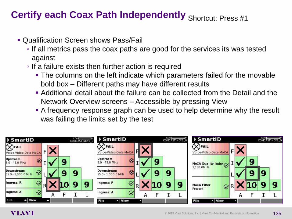
Certify each Coax Path Independently
Qualification Screen shows Pass/Fail
▫ If all metrics pass the coax paths are good for the services its was tested
against
▫ If a failure exists then further action is required
The columns on the left indicate which parameters failed for the movable
bold box – Different paths may have different results
Additional detail about the failure can be collected from the Detail and the
Network Overview screens – Accessible by pressing View
A frequency response graph can be used to help determine why the result
was failing the limits set by the test
Shortcut: Press #1

© 2015 Viavi Solutions, Inc. | Viavi Confidential and Proprietary Information 136
Seeing how everything is connected
Network Overview shows what is connected
▫ RF Tester can determine what it believes is connected and
where those elements have common connections
▫ Each element is shown on the topology map including:
splitters, filters, amplifiers, and found mismatches
▫ Users can easily identify if unexpected elements are
discovered and trace where those elements are located
before beginning to troubleshoot the coax network

© 2015 Viavi Solutions, Inc. | Viavi Confidential and Proprietary Information 137
Shows all items in the path between the two SmartIDs Shown –
Arrow Left and Right to highlight different segments
Each segment and element has additional information available
in the text box
Swap will reverse the orientation from left to right to ease
understanding on distances to elements
Details View
Swapped
Shortcut: Press #2

© 2015 Viavi Solutions, Inc. | Viavi Confidential and Proprietary Information 138
Shows POE to CPE for Full and Upstream Sweeps
User Arrow keys to See amplitude at a specific frequency
Type in the specific freq on the keypad
Press cancel button to go back
Sweep Trace – Freq Response Shortcut: Press #4
Upstream Freq Response Downstream Freq Response –
with MoCA filter in place

© 2015 Viavi Solutions, Inc. | Viavi Confidential and Proprietary Information 139
SmartID Screen Displays

© 2015 Viavi Solutions, Inc. | Viavi Confidential and Proprietary Information 140
MQI score relate to data rate over copper infrastructure
How quickly can I move data from host to client Set top Box

© 2015 Viavi Solutions, Inc. | Viavi Confidential and Proprietary Information 141
Summary of In-Home Wiring Options
Service Typical achievable Data Rate Distances
MoCA >100Mb/s typ. 140 MB/s max >300 ft.
HPNAv3 86-128 Mb/s typ >400 ft
802.11a/g ~10Mb/s Typical ~90 ft
802.11n ~40Mb/s Typical ~150 ft
HomePlug A/V 150 Mb/s Max published <300 estimated
Wired Ethernet 100 Mb/s 300 ft

© 2015 Viavi Solutions, Inc. | Viavi Confidential and Proprietary Information 142
Fundamental Rule
If the customers’ cabling system within the residence has physical layer problems,
it will not support the service!
…no matter how good the offering is or how much technology was applied
outside the home/apartment.
Troubleshooting Customer’s network is by invitation only.
© 2015 Viavi Solutions, Inc. | Viavi Confidential and Proprietary Information 143
Back to the Basics
Check for leakage sources
Check for ingress sources
Do a visual inspection of cable / connectors / passives
Replace questionable cable / connectors / passives
Tighten F-connectors per your company’s installation policy ▫ Be very careful not to over tighten connectors on CPE (TVs, VCRs, converters
etc.) and crack or damage input RFI integrity
© 2015 Viavi Solutions, Inc. | Viavi Confidential and Proprietary Information 144
Back to the Basics
Majority of problems are basic physical layer issues
Most of the tests remain the same
Check AC power
Check forward levels, analog and digital
Sweep – Critical for Frequency Response.
Understand which Tests To use Troubleshoot
© 2015 Viavi Solutions, Inc. | Viavi Confidential and Proprietary Information 145
Training… Training… Training…
▫ You never have too much training!
Learn everything you can about Triple Play & HFC networks ▫ Company sponsored training
▫ SCTE Chapter Meetings & Certification programs
▫ SCTE EXPO & Emerging Technologies
▫ CED and Communications Technology magazines
▫ Vendor “product specific” training
Learn everything you can about the devices in your network, both the physical
layer and data layer ▫ Headend: Modulators, Multiplexers, CMTS etc.
▫ Outside plant: Nodes, Amps, Passives etc.
▫ Subscriber’s drop: Digital Converter, DVRs, Cable Modems, eMTAs, house amps
etc.
Learn how to get the most out of your test equipment & CPE diagnostics ▫ most vendors will train you
▫ Be thorough - Take pride in your work! Do the installation right the first time
Take the time to properly certify every drop for Triple Play services

© 2015 Viavi Solutions, Inc. | Viavi Confidential and Proprietary Information 146
A 7/16” wrench is a “hi-tech” tool?!
“Finger tight ain’t
good enuff!”

© 2015 Viavi Solutions, Inc. | Viavi Confidential and Proprietary Information 147
Viavi Solutions – See Digital in a Whole New Light!
Questions?
See digital in a whole new light!

Mark Ortel
Sales Consultant Engineer
MAC Division www.viaviasolutions.com
National SCTE Member
Supporter of the National
And Local SCTE Chapters