proventia g intrusion prevention appliance quick …...proventia g intrusion prevention appliance...
TRANSCRIPT
®
G Intrusion PreventionAppliance
Quick Start Guide

Internet Security Systems, Inc.6303 Barfield RoadAtlanta, Georgia 30328-4233United States(404) 236-2600http://www.iss.net
© Internet Security Systems, Inc. 2003-2005. All rights reserved worldwide. Customers may make reasonable numbers of copies of this publication for internal use only. This publication may not otherwise be copied or reproduced, in whole or in part, by any other person or entity without the express prior written consent of Internet Security Systems, Inc.
Patent pending.
Internet Security Systems, ADDME, ActiveAlert, AlertCon, the AlertCon logos, FireCell, FlexCheck, SecurityFusion, SecurePartner, SiteProtector, SecureU, System Scanner, Virtual Patch, Wireless Scanner, and X-Press Update are trademarks and service marks; Database Scanner, Internet Scanner, the Internet Security Systems logo, Online Scanner, Proventia, RealSecure, SAFEsuite, Secure Steps, and X-Force are registered trademarks and service marks of Internet Security Systems, Inc. Network ICE, the Network ICE logo, and ICEpac are trademarks, BlackICE a licensed trademark, and ICEcap a registered trademark of Network ICE Corporation, a wholly owned subsidiary of Internet Security Systems, Inc. Powering Content Security is a trademark and Cobion is a registered trademark of Cobion AG, a wholly owned subsidiary of Internet Security Systems, Inc. SilentRunner is a registered trademark of Raytheon Company. Acrobat and Adobe are registered trademarks of Adobe Systems Incorporated. Certicom is a trademark and Security Builder is a registered trademark of Certicom Corp. Check Point, FireWall-1, OPSEC, Provider-1, and VPN-1 are registered trademarks of Check Point Software Technologies Ltd. or its affiliates. Cisco and Cisco IOS are registered trademarks of Cisco Systems, Inc. HP-UX and OpenView are registered trademarks of Hewlett-Packard Company. IBM and AIX are registered trademarks of IBM Corporation. InstallShield is a registered trademark and service mark of InstallShield Software Corporation in the United States and/or other countries. Intel and Pentium are registered trademarks of Intel. Lucent is a trademark of Lucent Technologies, Inc. ActiveX, Microsoft, Windows, and Windows NT are either registered trademarks or trademarks of Microsoft Corporation. Net8, Oracle, Oracle8, SQL*Loader, and SQL*Plus are trademarks or registered trademarks of Oracle Corporation. Seagate Crystal Reports, Seagate Info, Seagate, Seagate Software, and the Seagate logo are trademarks or registered trademarks of Seagate Software Holdings, Inc. and/or Seagate Technology, Inc. Secure Shell and SSH are trademarks or registered trademarks of SSH Communications Security. iplanet, Sun, Sun Microsystems, the Sun Logo, Netra, SHIELD, Solaris, SPARC, and UltraSPARC are trademarks or registered trademarks of Sun Microsystems, Inc. in the United States and other countries. All SPARC trademarks are used under license and are trademarks or registered trademarks of SPARC International, Inc. in the United States and other countries. Adaptive Server, SQL, SQL Server, and Sybase are trademarks of Sybase, Inc., its affiliates and licensers. Tivoli is a registered trademark of Tivoli Systems Inc. UNIX is a registered trademark in the United States and other countries, licensed exclusively through X/Open Company, Ltd. All other trademarks are the property of their respective owners and are used here in an editorial context without intent of infringement. Specifications are subject to change without notice.
© Intel Corporation, 2002.
Disclaimer: The information contained in this document may change without notice, and may have been altered or changed if you have received it from a source other than ISS or the X-Force. Use of this information constitutes acceptance for use in an “AS IS” condition, without warranties of any kind, and any use of this information is at the user’s own risk. ISS and the X-Force disclaim all warranties, either expressed or implied, including the warranties of merchantability and fitness for a particular purpose. In no event shall ISS or the X-Force be liable for any damages whatsoever, including direct, indirect, incidental, consequential or special damages, arising from the use or dissemination hereof, even if ISS or the X-Force has been advised of the possibility of such damages. Some states do not allow the exclusion or limitation of liability for consequential or incidental damages, so the foregoing limitation may not apply.
Reference herein to any specific commercial products, process, or service by trade name, trademark, manufacturer, or otherwise, does not necessarily constitute or imply its endorsement, recommendation, or favoring by Internet Security Systems, Inc. The views and opinions of authors expressed herein do not necessarily state or reflect those of Internet Security Systems, Inc., and shall not be used for advertising or product endorsement purposes.
Links and addresses to Internet resources are inspected thoroughly prior to release, but the ever-changing nature of the Internet prevents Internet Security Systems from guaranteeing the content or existence of the resource. When possible, the reference contains alternate sites or keywords that could be used to acquire the information by other methods. If you find a broken or inappropriate link, please send an email with the topic name, link, and its behavior to [email protected].
Document part number: DOC-QSG-PROVIPAG-006-C
February 24, 2006
Contents
Preface. . . . . . . . . . . . . . . . . . . . . . . . . . . . . . . . . . . . . . . . . . . . . . . . . . . . . . . 5Overview . . . . . . . . . . . . . . . . . . . . . . . . . . . . . . . . . . . . . . . . . . . . . . . . . . . . . . 5Getting Started . . . . . . . . . . . . . . . . . . . . . . . . . . . . . . . . . . . . . . . . . . . . . . . . . . 9
Chapter 1: Connecting the ApplianceOverview . . . . . . . . . . . . . . . . . . . . . . . . . . . . . . . . . . . . . . . . . . . . . . . . . . . . . 11The G100/G200/G1000 and G1200 Front and Back Panels . . . . . . . . . . . . . . . . . 12The G400 and G2000 Front and Back Panels . . . . . . . . . . . . . . . . . . . . . . . . . . . . 20Standard Inline Deployment Scenarios . . . . . . . . . . . . . . . . . . . . . . . . . . . . . . . . . 27Connecting the Cables and Starting the Appliance . . . . . . . . . . . . . . . . . . . . . . . . . 30Configuring the Appliance External Bypass Unit . . . . . . . . . . . . . . . . . . . . . . . . . . . 32
Chapter 2: Configuring the ApplianceOverview . . . . . . . . . . . . . . . . . . . . . . . . . . . . . . . . . . . . . . . . . . . . . . . . . . . . . 37Configuration Checklist . . . . . . . . . . . . . . . . . . . . . . . . . . . . . . . . . . . . . . . . . . . . 38Logging On and Configuring the Appliance . . . . . . . . . . . . . . . . . . . . . . . . . . . . . . . 40Accessing Proventia Manager . . . . . . . . . . . . . . . . . . . . . . . . . . . . . . . . . . . . . . . 45Managing the Appliance . . . . . . . . . . . . . . . . . . . . . . . . . . . . . . . . . . . . . . . . . . . 48Reinstalling the Appliance . . . . . . . . . . . . . . . . . . . . . . . . . . . . . . . . . . . . . . . . . . 51Getting Technical Support . . . . . . . . . . . . . . . . . . . . . . . . . . . . . . . . . . . . . . . . . . 53
Index . . . . . . . . . . . . . . . . . . . . . . . . . . . . . . . . . . . . . . . . . . . . . . . . . . . . . . . . 57
3Proventia G Intrusion Prevention Appliance Quick Start Guide

Contents
4
Preface
Overview
Introduction This guide is designed to help you connect and configure your Proventia G Intrusion Prevention Appliance.
Scope This guide describes the appliance models (G100, G200, G1000 and G1200, G400, G400 (Rev A) and G2000) and explains the different ways to connect the appliances to your network. It also includes initial appliance setup procedures.
Important: To upgrade legacy G100, G200, G1000 and G1200 model appliances to firmware version 1.2, see Proventia G Next Generation Installation and Upgrade Procedures. To configure and manage appliances running firmware version 1.2, see the Proventia G Intrusion Prevention Appliances User Guide.
Additional documentation is located on the ISS Web site at http://www.iss.net/support/documentation.
Audience This guide is intended for network security system administrators responsible for installing and configuring Proventia G Intrusion Prevention Appliances. A fundamental knowledge of network security policies and IP network configuration is helpful.
5Proventia G Intrusion Prevention Appliance Quick Start Guide
Preface
What’s new in this release
The new features in this release include the following:
� G100, G200, G1000, and G1200 appliance management through Proventia Manager. Manage appliance settings using the Web-based Proventia Manager interface.
� Ignore response available for Security Events and Response Filters. Manually set the Ignore response to tell the appliance to ignore events that are not a threat to your network, reducing the number of events you need to track.
� Enhanced diagnostics and statistics. Using the Driver, Packet Analysis, and Protection statistics, view network traffic the appliance has processed to troubleshoot or to determine important trends.
Other changes in this release include:
� for G400 and G2000 models, the ability to configure high availability (HA) through Proventia Manager
� card management is now called adapter management
� SNMP read access configuration
� ability to configure kill port link settings
Important: You must update SiteProtector to the 5.18 Database Service Pack prior to installing the Proventia G firmware version 1.2. See the Readme for more information.
Verifying package contents
The Proventia G appliance packaging includes the following:
� appliance
� power cord
� appliance recovery CD
� null modem serial cable
� warranty statement
� bezel cover with keys
� mouse/keyboard Y-cable
� crossover connectors and patch cables (copper only)
� rack mount kits and instructions
6
Overview
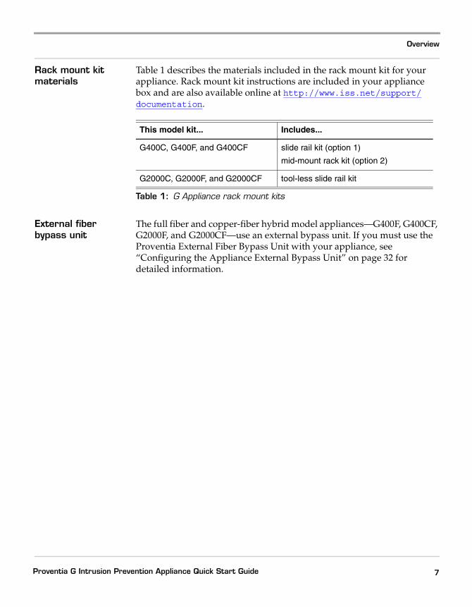
Rack mount kit materials
Table 1 describes the materials included in the rack mount kit for your appliance. Rack mount kit instructions are included in your appliance box and are also available online at http://www.iss.net/support/documentation.
External fiber bypass unit
The full fiber and copper-fiber hybrid model appliances—G400F, G400CF, G2000F, and G2000CF—use an external bypass unit. If you must use the Proventia External Fiber Bypass Unit with your appliance, see “Configuring the Appliance External Bypass Unit” on page 32 for detailed information.
This model kit... Includes...
G400C, G400F, and G400CF slide rail kit (option 1)
mid-mount rack kit (option 2)
G2000C, G2000F, and G2000CF tool-less slide rail kit
Table 1: G Appliance rack mount kits
7Proventia G Intrusion Prevention Appliance Quick Start Guide
Preface
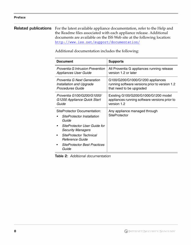
Related publications For the latest available appliance documentation, refer to the Help and the Readme files associated with each appliance release. Additional documents are available on the ISS Web site at the following location: http://www.iss.net/support/documentation/
Additional documentation includes the following:
Document Supports
Proventia G Intrusion Prevention Appliances User Guide
All Proventia G appliances running release version 1.2 or later
Proventia G Next Generation Installation and Upgrade Procedures Guide
G100/G200/G1000/G1200 appliances running software versions prior to version 1.2 that need to be upgraded
Proventia G100/G200/G1000/G1200 Appliance Quick Start Guide
Existing G100/G200/G1000/G1200 model appliances running software versions prior to version 1.2
SiteProtector Documentation:
• SiteProtector Installation Guide
• SiteProtector User Guide for Security Managers
• SiteProtector Technical Reference Guide
• SiteProtector Best Practices Guide
Any appliance managed through SiteProtector
Table 2: Additional documentation
8
Getting Started
Getting Started
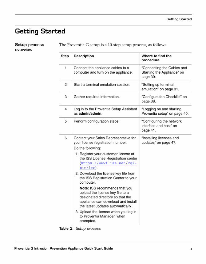
Setup process overview
The Proventia G setup is a 10-step setup process, as follows:
Step Description Where to find the procedure
1 Connect the appliance cables to a computer and turn on the appliance.
“Connecting the Cables and Starting the Appliance” on page 30.
2 Start a terminal emulation session. “Setting up terminal emulation” on page 31.
3 Gather required information. “Configuration Checklist” on page 38.
4 Log in to the Proventia Setup Assistant as admin/admin.
“Logging on and starting Proventia setup” on page 40.
5 Perform configuration steps. “Configuring the network interface and host” on page 41.
6 Contact your Sales Representative for your license registration number.
Do the following:
1. Register your customer license at the ISS License Registration center (https://www1.iss.net/cgi-bin/lrc).
2. Download the license key file from the ISS Registration Center to your computer.
Note: ISS recommends that you upload the license key file to a designated directory so that the appliance can download and install the latest updates automatically.
3. Upload the license when you log in to Proventia Manager, when prompted.
“Installing licenses and updates” on page 47.
Table 3: Setup process
9Proventia G Intrusion Prevention Appliance Quick Start Guide

Preface
7 Verify you have the following:
• Internet Explorer version 6.0 or later
• Java Runtime Environment (JRE) version 1.4.2. The application prompts you with an installation link if you do not have it installed.
“Accessing Proventia Manager” on page 45.
8 Open Internet Explorer and log in to Proventia Manager as username admin and the password you configured during Proventia Setup.
“Logging on to Proventia Manager” on page 45.
9 Install license. “Installing licenses and updates” on page 47
10 Apply updates.
Step Description Where to find the procedure
Table 3: Setup process (Continued)
10
Chapter 1
Connecting the Appliance
Overview
Introduction This chapter contains diagrams and connection procedures all appliances, as well as standard inline deployment scenarios and information on connecting the external fiber bypass unit.
In this chapter This chapter contains the following topics:
Topic Page
The G100/G200/G1000 and G1200 Front and Back Panels 12
The G400 and G2000 Front and Back Panels 20
Standard Inline Deployment Scenarios 27
Connecting the Cables and Starting the Appliance 30
Configuring the Appliance External Bypass Unit 32
11Proventia G Intrusion Prevention Appliance Quick Start Guide
Chapter 1: Connecting the Appliance
The G100/G200/G1000 and G1200 Front and Back Panels
Introduction This topic identifies the front and back panels of a Proventia G100, G200, G1000, and G1200 appliance, along with descriptions for each item.
Front panel diagram and legend
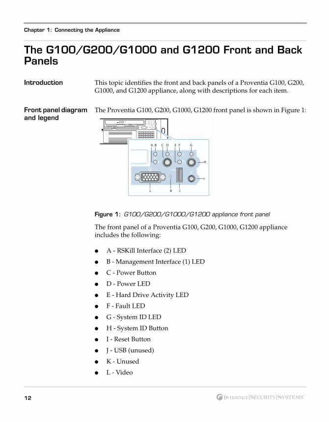
The Proventia G100, G200, G1000, G1200 front panel is shown in Figure 1:
Figure 1: G100/G200/G1000/G1200 appliance front panel
The front panel of a Proventia G100, G200, G1000, G1200 appliance includes the following:
� A - RSKill Interface (2) LED
� B - Management Interface (1) LED
� C - Power Button
� D - Power LED
� E - Hard Drive Activity LED
� F - Fault LED
� G - System ID LED
� H - System ID Button
� I - Reset Button
� J - USB (unused)
� K - Unused
� L - Video
L JK
H
I
BA F GEDC
12
The G100/G200/G1000 and G1200 Front and Back Panels
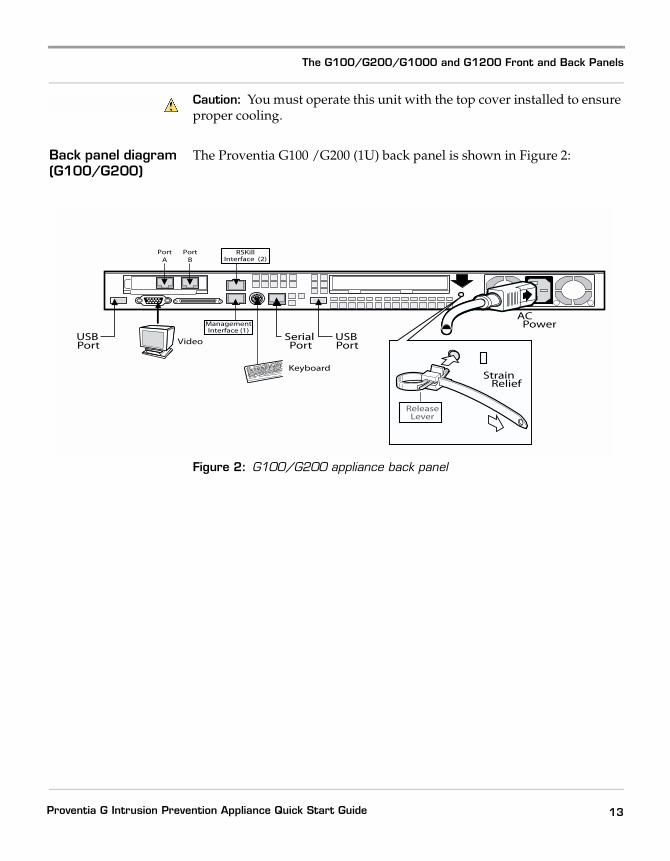
Caution: You must operate this unit with the top cover installed to ensure proper cooling.
Back panel diagram (G100/G200)
The Proventia G100 /G200 (1U) back panel is shown in Figure 2:
Figure 2: G100/G200 appliance back panel
AC Power
SerialPort
USBPort
USBPort Video
Keyboard
ReleaseLever
RSKillInterface (2)
PortA
PortB
ManagementInterface (1)
Strain Relief
13Proventia G Intrusion Prevention Appliance Quick Start Guide
Chapter 1: Connecting the Appliance
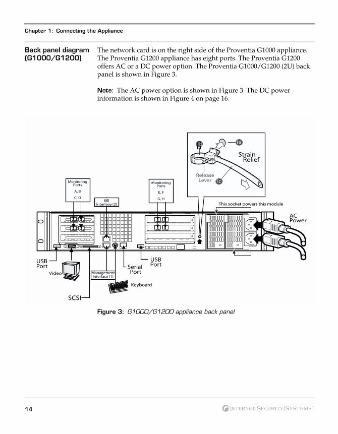
Back panel diagram (G1000/G1200)
The network card is on the right side of the Proventia G1000 appliance. The Proventia G1200 appliance has eight ports. The Proventia G1200 offers AC or a DC power option. The Proventia G1000/G1200 (2U) back panel is shown in Figure 3.
Note: The AC power option is shown in Figure 3. The DC power information is shown in Figure 4 on page 16.
Figure 3: G1000/G1200 appliance back panel
SCSI
Keyboard
Video
ACPower
This socket powers this moduleKill
Interface (2)
SerialPort
USBPort
USBPort
ManagementInterface (1)
ReleaseLever
1a1b
1c
Strain Relief
MonitoringPorts
A, B
C, D
MonitoringPorts
E, F
G, H
14
The G100/G200/G1000 and G1200 Front and Back Panels
Connecting the AC power cord
The Proventia G100/G200 (1U) appliances come with one AC power connector. The Proventia G1000/G1200 (2U) appliances come with dual standard AC power connectors and a DC power option (G1200 only).
To connect the AC power cord(s):
1. Press the strain relief into the platform hole until it snaps into place.
2. Place the power cord into the loop. Leave some slack in the power cord between the strain relief and the power supply.
3. Pull the tab to secure the power cord in the loop.
4. Insert the female end the power cord into the back of the appliance as shown in Figure 2 and Figure 3.
5. Insert the male end of the power cord into a standard AC power supply.
DC power supply The DC power supply used with the Proventia G1200 appliance uses a -48 to -60 VDC input switching power subsystem, which provides up to 470 Watts with -48 to -60 VDC input and with current and remote sense regulation. The power subsystem consists of one or two 470-Watt power supply modules. A system with two modules forms a redundant, hot-swappable (1+1) power subsystem.
Note: The DC power supply is only available for the Proventia G1200 appliance.
15Proventia G Intrusion Prevention Appliance Quick Start Guide
Chapter 1: Connecting the Appliance
Back panel diagram (G1200)
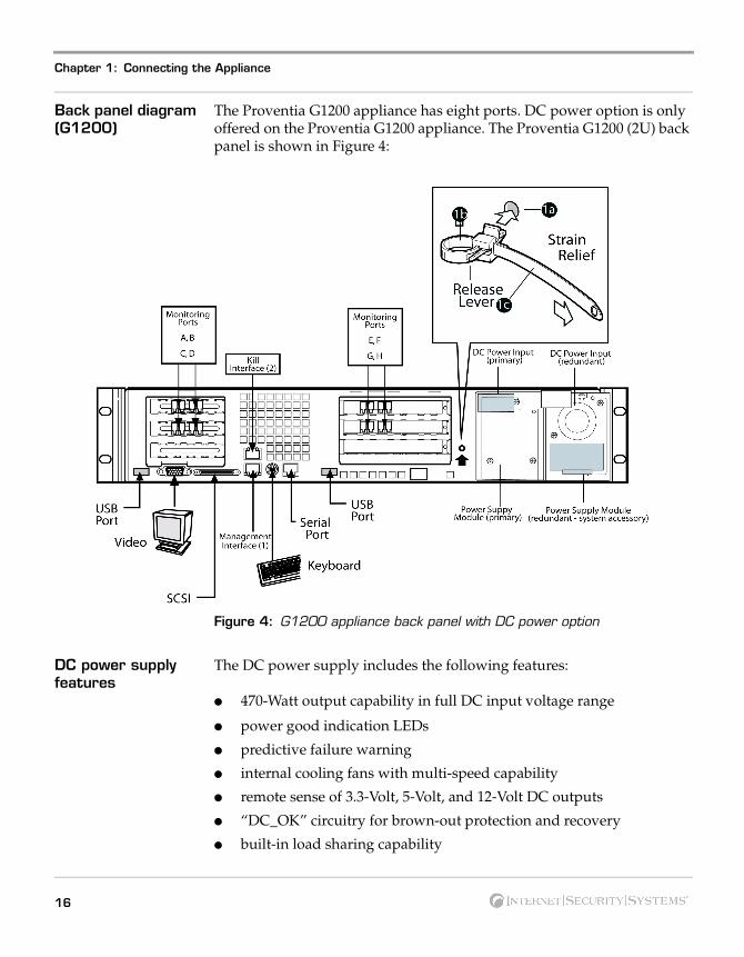
The Proventia G1200 appliance has eight ports. DC power option is only offered on the Proventia G1200 appliance. The Proventia G1200 (2U) back panel is shown in Figure 4:
Figure 4: G1200 appliance back panel with DC power option
DC power supply features
The DC power supply includes the following features:
� 470-Watt output capability in full DC input voltage range
� power good indication LEDs
� predictive failure warning
� internal cooling fans with multi-speed capability
� remote sense of 3.3-Volt, 5-Volt, and 12-Volt DC outputs
� “DC_OK” circuitry for brown-out protection and recovery
� built-in load sharing capability
16
The G100/G200/G1000 and G1200 Front and Back Panels
� built-in overloading protection capability
� onboard field replaceable unit (FRU) information
� I2C interface for server management functions
� integral handle for insertion/extraction
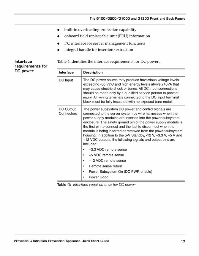
Interface requirements for DC power
Table 4 identifies the interface requirements for DC power:
Interface Description
DC Input The DC power source may produce hazardous voltage levels exceeding -60 VDC and high energy levels above 240VA that may cause electric shock or burns. All DC input connections should be made only by a qualified service person to prevent injury. All wiring terminals connected to the DC input terminal block must be fully insulated with no exposed bare metal.
DC Output Connectors
The power subsystem DC power and control signals are connected to the server system by wire harnesses when the power supply modules are inserted into the power subsystem enclosure. The safety ground pin of the power supply module is the first pin to connect and the last to disconnect when the module is being inserted or removed from the power subsystem housing. In addition to the 5-V Standby, -12 V, +3.3 V, +5 V and +12 VDC outputs, the following signals and output pins are included:
• +3.3 VDC remote sense
• +5 VDC remote sense
• +12 VDC remote sense
• Remote sense return
• Power Subsystem On (DC PWR enable)
• Power Good
Table 4: Interface requirements for DC power
17Proventia G Intrusion Prevention Appliance Quick Start Guide
Chapter 1: Connecting the Appliance
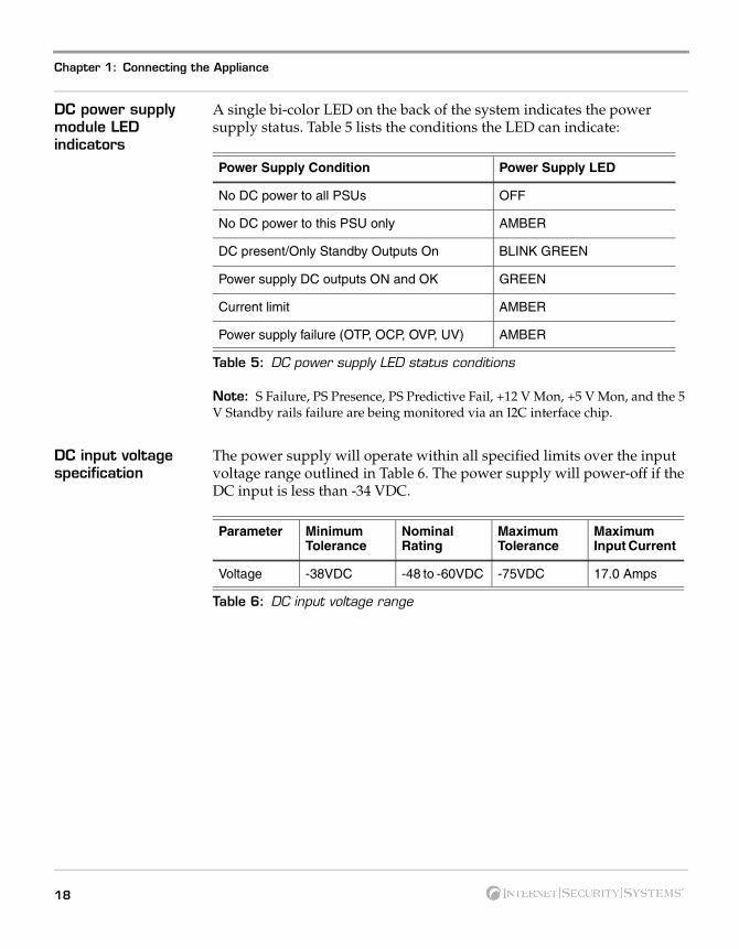
DC power supply module LED indicators
A single bi-color LED on the back of the system indicates the power supply status. Table 5 lists the conditions the LED can indicate:
Note: S Failure, PS Presence, PS Predictive Fail, +12 V Mon, +5 V Mon, and the 5 V Standby rails failure are being monitored via an I2C interface chip.
DC input voltage specification
The power supply will operate within all specified limits over the input voltage range outlined in Table 6. The power supply will power-off if the DC input is less than -34 VDC.
Power Supply Condition Power Supply LED
No DC power to all PSUs OFF
No DC power to this PSU only AMBER
DC present/Only Standby Outputs On BLINK GREEN
Power supply DC outputs ON and OK GREEN
Current limit AMBER
Power supply failure (OTP, OCP, OVP, UV) AMBER
Table 5: DC power supply LED status conditions
Parameter MinimumTolerance
Nominal Rating
MaximumTolerance
Maximum Input Current
Voltage -38VDC -48 to -60VDC -75VDC 17.0 Amps
Table 6: DC input voltage range
18
The G100/G200/G1000 and G1200 Front and Back Panels
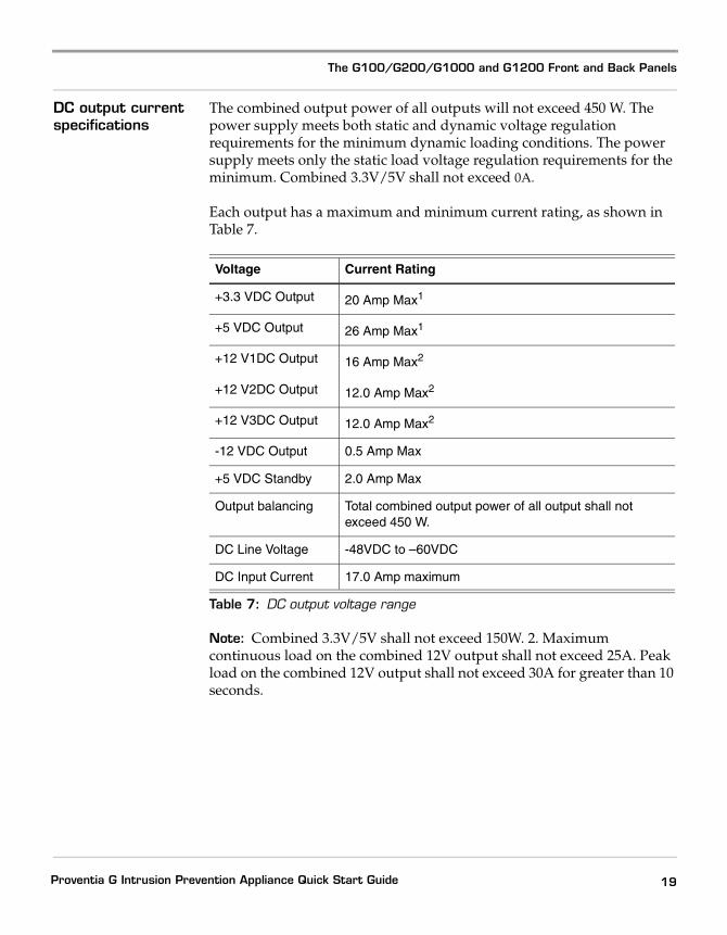
DC output current specifications
The combined output power of all outputs will not exceed 450 W. The power supply meets both static and dynamic voltage regulation requirements for the minimum dynamic loading conditions. The power supply meets only the static load voltage regulation requirements for the minimum. Combined 3.3V/5V shall not exceed 0A.
Each output has a maximum and minimum current rating, as shown in Table 7.
Note: Combined 3.3V/5V shall not exceed 150W. 2. Maximum continuous load on the combined 12V output shall not exceed 25A. Peak load on the combined 12V output shall not exceed 30A for greater than 10 seconds.
Voltage Current Rating
+3.3 VDC Output 20 Amp Max1
+5 VDC Output 26 Amp Max1
+12 V1DC Output 16 Amp Max2
+12 V2DC Output 12.0 Amp Max2
+12 V3DC Output 12.0 Amp Max2
-12 VDC Output 0.5 Amp Max
+5 VDC Standby 2.0 Amp Max
Output balancing Total combined output power of all output shall not exceed 450 W.
DC Line Voltage -48VDC to –60VDC
DC Input Current 17.0 Amp maximum
Table 7: DC output voltage range
19Proventia G Intrusion Prevention Appliance Quick Start Guide
Chapter 1: Connecting the Appliance
The G400 and G2000 Front and Back Panels
Introduction This topic identifies the front and back panels of the G400, G400 (Rev A) and G2000 appliances, along with descriptions for each item, including the external bypass unit.
Identifying the G400 (Rev A) appliance model
To determine the G400 (Rev A) appliance model, check the serial number and model label. It should say “Model G400 Rev: A.”
Note: The G400 (Rev A) hardware port configurations are the same as the G2000 model. Refer to the appropriate diagram for your appliance model for information about ports and external bypass connectivity.
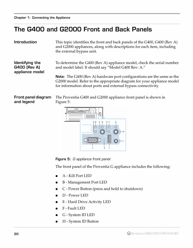
Front panel diagram and legend
The Proventia G400 and G2000 appliance front panel is shown in Figure 5:
Figure 5: G appliance front panel
The front panel of the Proventia G appliance includes the following:
� A - Kill Port LED
� B - Management Port LED
� C - Power Button (press and hold to shutdown)
� D - Power LED
� E - Hard Drive Activity LED
� F - Fault LED
� G - System ID LED
� H - System ID Button
L JK
H
I
BA F GEDC
20
The G400 and G2000 Front and Back Panels
� I - Reset Button
� J - USB (unused)
� K - Unused
� L - Video
Caution: You must operate this unit with the top cover installed to ensure proper cooling. A fault LED light generally does not indicate a problem with the appliance itself. The light can appear if the power cord is not plugged in properly.
21Proventia G Intrusion Prevention Appliance Quick Start Guide
Chapter 1: Connecting the Appliance
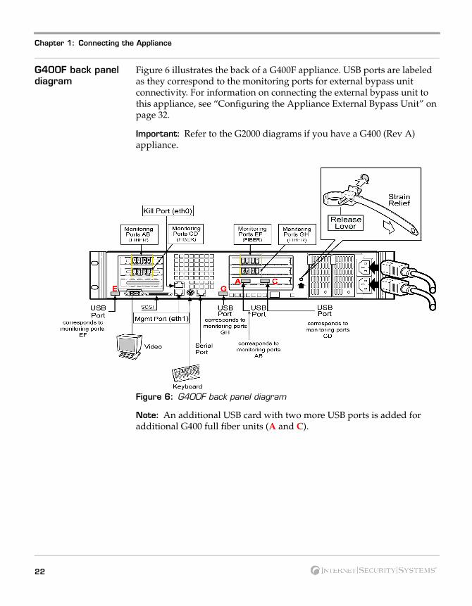
G400F back panel diagram
Figure 6 illustrates the back of a G400F appliance. USB ports are labeled as they correspond to the monitoring ports for external bypass unit connectivity. For information on connecting the external bypass unit to this appliance, see “Configuring the Appliance External Bypass Unit” on page 32.
Important: Refer to the G2000 diagrams if you have a G400 (Rev A) appliance.
Figure 6: G400F back panel diagram
Note: An additional USB card with two more USB ports is added for additional G400 full fiber units (A and C).
22
The G400 and G2000 Front and Back Panels
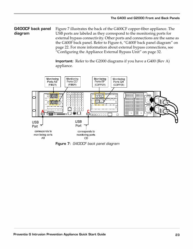
G400CF back panel diagram
Figure 7 illustrates the back of the G400CF copper-fiber appliance. The USB ports are labeled as they correspond to the monitoring ports for external bypass connectivity. Other ports and connections are the same as the G400F back panel. Refer to Figure 6, “G400F back panel diagram” on page 22. For more information about external bypass connections, see “Configuring the Appliance External Bypass Unit” on page 32.
Important: Refer to the G2000 diagrams if you have a G400 (Rev A) appliance.
Figure 7: G400CF back panel diagram
23Proventia G Intrusion Prevention Appliance Quick Start Guide
Chapter 1: Connecting the Appliance
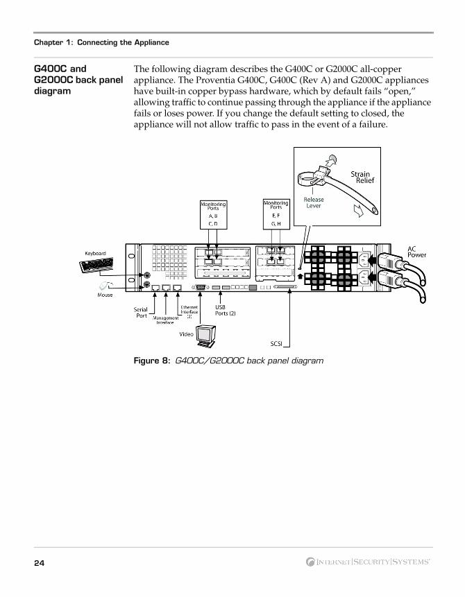
G400C and G2000C back panel diagram
The following diagram describes the G400C or G2000C all-copper appliance. The Proventia G400C, G400C (Rev A) and G2000C appliances have built-in copper bypass hardware, which by default fails “open,” allowing traffic to continue passing through the appliance if the appliance fails or loses power. If you change the default setting to closed, the appliance will not allow traffic to pass in the event of a failure.
Figure 8: G400C/G2000C back panel diagram
24
The G400 and G2000 Front and Back Panels
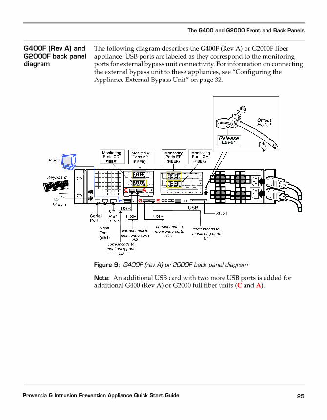
G400F (Rev A) and G2000F back panel diagram
The following diagram describes the G400F (Rev A) or G2000F fiber appliance. USB ports are labeled as they correspond to the monitoring ports for external bypass unit connectivity. For information on connecting the external bypass unit to these appliances, see “Configuring the Appliance External Bypass Unit” on page 32.
Figure 9: G400F (rev A) or 2000F back panel diagram
Note: An additional USB card with two more USB ports is added for additional G400 (Rev A) or G2000 full fiber units (C and A).
25Proventia G Intrusion Prevention Appliance Quick Start Guide
Chapter 1: Connecting the Appliance
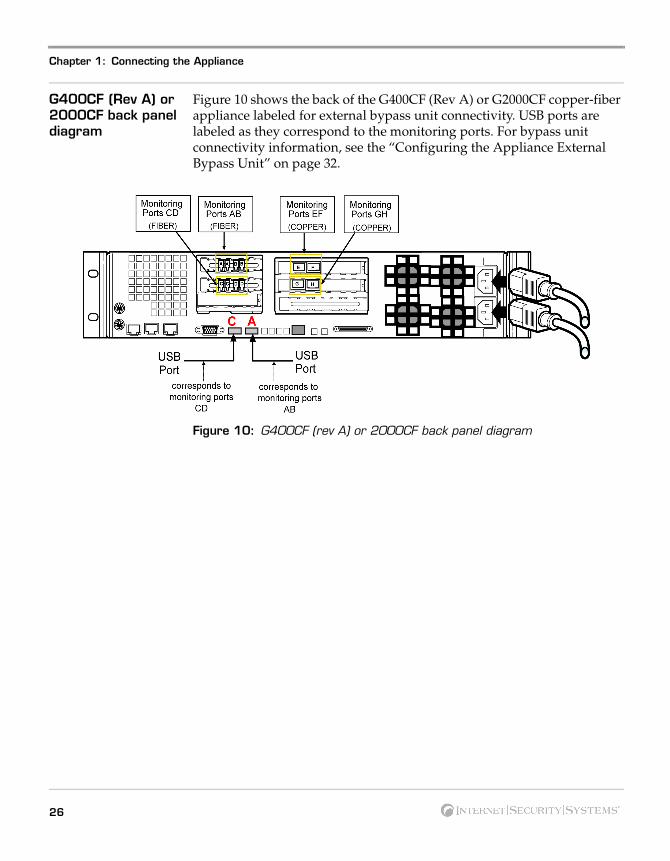
G400CF (Rev A) or 2000CF back panel diagram
Figure 10 shows the back of the G400CF (Rev A) or G2000CF copper-fiber appliance labeled for external bypass unit connectivity. USB ports are labeled as they correspond to the monitoring ports. For bypass unit connectivity information, see the “Configuring the Appliance External Bypass Unit” on page 32.
Figure 10: G400CF (rev A) or 2000CF back panel diagram
26
Standard Inline Deployment Scenarios
Standard Inline Deployment Scenarios
Introduction The Proventia G400C, G400C (Rev A) and G2000C appliances have built-in copper bypass hardware, which by default fails “open,” allowing traffic to continue passing through the appliance if the appliance fails or loses power. If you change the default setting to closed, the appliance will not allow traffic to pass in the event of a failure.
The G400F, G400CF, G400F (Rev A) G400CF (Rev A) and G2000F and G2000CF do not have built-in bypass hardware. You can purchase an optional fiber bypass unit and kit that provides bypass functionality. Contact Internet Security Systems for availability. See “Configuring the Appliance External Bypass Unit” on page 32 for more information.
Note: These models require the external bypass unit for the fiber ports only.
Caution: You should install the correct network cabling and verify that traffic flows before you turn on the appliance.
Cabling guidelines Place a CAT5 crossover cable between a Proventia G appliance and a server or a workstation. ISS recommends using a CAT5 crossover cable between a Proventia G appliance and a router. A straight cable is sufficient between a Proventia G appliance and a switch or hub.
Note: Where a crossover is needed, you may use your own CAT5 crossover cable or the provided one-foot cable and crossover coupler that comes with the appliance. When the appliance is not running, its monitoring ports function as a crossover. The following scenarios work independently of the monitoring port (A or B) you use.
27Proventia G Intrusion Prevention Appliance Quick Start Guide
Chapter 1: Connecting the Appliance
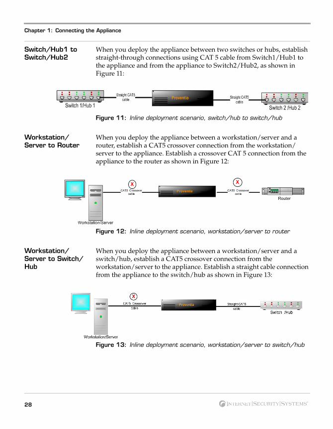
Switch/Hub1 to Switch/Hub2
When you deploy the appliance between two switches or hubs, establish straight-through connections using CAT 5 cable from Switch1/Hub1 to the appliance and from the appliance to Switch2/Hub2, as shown in Figure 11:
Figure 11: Inline deployment scenario, switch/hub to switch/hub
Workstation/Server to Router
When you deploy the appliance between a workstation/server and a router, establish a CAT5 crossover connection from the workstation/server to the appliance. Establish a crossover CAT 5 connection from the appliance to the router as shown in Figure 12:
Figure 12: Inline deployment scenario, workstation/server to router
Workstation/Server to Switch/Hub
When you deploy the appliance between a workstation/server and a switch/hub, establish a CAT5 crossover connection from the workstation/server to the appliance. Establish a straight cable connection from the appliance to the switch/hub as shown in Figure 13:
Figure 13: Inline deployment scenario, workstation/server to switch/hub
28

Standard Inline Deployment Scenarios
Router to Switch/Hub
When you deploy the appliance between a router and a switch/hub, establish a CAT5 crossover connection from the router to the appliance. Establish a straight cable connection from the appliance to the switch/hub as shown in Figure 14:
Figure 14: Inline deployment scenario, router to switch/hub
Router to Router When you deploy the appliance between two routers, establish a CAT5 crossover connection from Router 1 to the appliance, and from the appliance to Router 2, as shown in Figure 15:
Figure 15: Inline deployment scenario, Router to Router
High Availability Deployment
Appliances cannot be configured for high availability (HA) mode during the initial setup in the Proventia Setup Utility. Select one of the standard appliance modes during the initial setup, and then refer to High Availability Configuration topics in the Proventia G Intrusion Prevention Appliances User Guide or the Help for detailed procedures for enabling HA modes.
29Proventia G Intrusion Prevention Appliance Quick Start Guide
Chapter 1: Connecting the Appliance
Connecting the Cables and Starting the Appliance
Introduction This topic provides instructions for connecting cables and starting the appliance for the first time.
Important: Ensure that you keep your management and monitoring communication separate so that network traffic will be allowed to pass uninterrupted through the appliance’s network interface card (NIC).
Connecting the power cord
The appliances have dual standard AC power connectors.
To connect the power cord(s):
1. Press the strain relief into the platform hole until it snaps into place.
2. Insert the power cord into the loop.
Note: Leave some slack in the power cord between the strain relief and the power supply.
3. Pull the tab to secure the power cord in the loop.
4. Plug one end of the power cord into the back of the appliance.
5. Plug the other end of the power cord(s) into a standard AC power supply.
Connecting the network cables
To connect the network cables:
1. Connect the management port (eth1) on the back panel to the network you will use to manage it.
2. Connect the network cables to correspond with the adapter mode (inline or passive) you plan to use for the appliance.
Note: Only connect the Kill port if you want the appliance to send kill responses through the Kill port while in monitoring mode.
Reference: If you configure the appliance to operate in inline protection or inline simulation modes, see “Standard Inline Deployment Scenarios” on page 27.
30
Connecting the Cables and Starting the Appliance
Connecting to the appliance for first time setup
To connect to the appliance:
1. Ensure the appliance is on.
2. Connect the CAT5 cable from your management interface (eth1) to your hub or switch.
3. Plug one end of the null modem (serial) cable into the serial port on the back of the appliance (Figure 6 or Figure 9, depending on your appliance model).
4. Plug the other end of the serial cable into the serial port on your computer or laptop.
5. Use a terminal emulation program, such as Hyperterminal, to create a connection to the appliance.
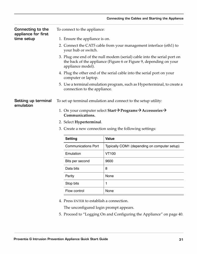
Setting up terminal emulation
To set up terminal emulation and connect to the setup utility:
1. On your computer select Start!Programs!Accessories!Communications.
2. Select Hyperterminal.
3. Create a new connection using the following settings:
4. Press ENTER to establish a connection.
The unconfigured login prompt appears.
5. Proceed to “Logging On and Configuring the Appliance” on page 40.
Setting Value
Communications Port Typically COM1 (depending on computer setup)
Emulation VT100
Bits per second 9600
Data bits 8
Parity None
Stop bits 1
Flow control None
31Proventia G Intrusion Prevention Appliance Quick Start Guide
Chapter 1: Connecting the Appliance
Configuring the Appliance External Bypass Unit
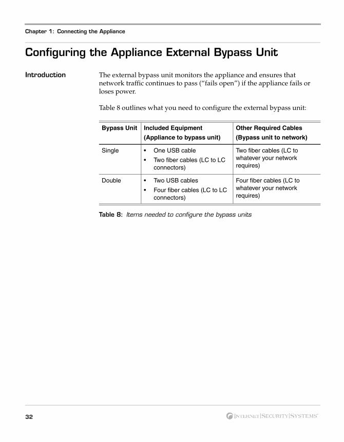
Introduction The external bypass unit monitors the appliance and ensures that network traffic continues to pass (“fails open”) if the appliance fails or loses power.
Table 8 outlines what you need to configure the external bypass unit:
Table 8: Items needed to configure the bypass units
Bypass Unit Included Equipment
(Appliance to bypass unit)
Other Required Cables
(Bypass unit to network)
Single • One USB cable
• Two fiber cables (LC to LC connectors)
Two fiber cables (LC to whatever your network requires)
Double • Two USB cables
• Four fiber cables (LC to LC connectors)
Four fiber cables (LC to whatever your network requires)
32
Configuring the Appliance External Bypass Unit
Configuration diagram
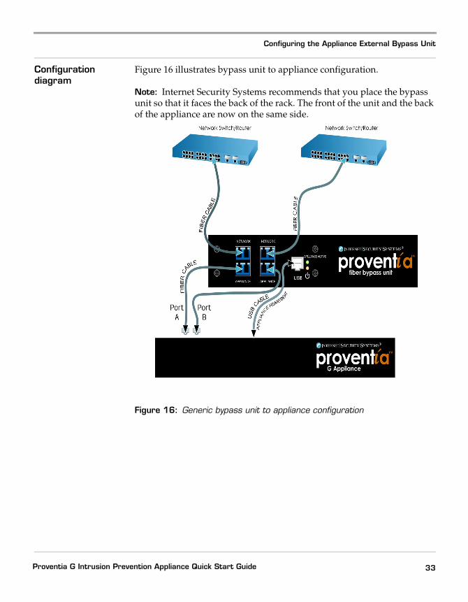
Figure 16 illustrates bypass unit to appliance configuration.
Note: Internet Security Systems recommends that you place the bypass unit so that it faces the back of the rack. The front of the unit and the back of the appliance are now on the same side.
Figure 16: Generic bypass unit to appliance configuration
33Proventia G Intrusion Prevention Appliance Quick Start Guide
Chapter 1: Connecting the Appliance
Before you connect the appliance
For each USB port to be correctly associated with the corresponding pair of monitoring ports, you must connect the USB cables before you turn on the appliance. If you connect or disconnect any USB cables while the appliance is on, you must restart the appliance.
Note: If you are unsure whether your appliance is full fiber or copper, refer to ports on the back of the appliance.
Caution: If you disconnect or change USB port connections, or replace interface cards after the appliance and bypass unit are initialized, the system may renumber the USB ports. ISS recommends that you set up the connections as described in this topic. If you need to adjust your ports, you must turn off the appliance, and then reconfigure your port settings.
Connecting the cables
To connect the bypass unit to the appliance:
Important: The appliance MUST be OFF before you connect the appliance to the external bypass unit.
1. Connect the fiber cables from the network ports on the bypass unit to your network switch and routers.
2. Verify that traffic is flowing between the network and the appliance.
Tip: If you can ping the appliance, traffic is flowing between the network and the appliance.
3. Connect the fiber cables (included with the appliance) from the ports on bypass unit to the corresponding ports on the back of the appliance.
4. Connect the USB cable from the USB port on the bypass unit to the correct USB port(s) on the back of the appliance.
Connecting the G400F and CF appliances
This topic describes how to connect an external bypass unit to the G400F and G400CF appliances. Refer to the back panel diagrams corresponding to your appliance model.
Important: If you have a G400 (Rev A) appliance, refer to the G2000 diagrams for connectivity information.
34

Configuring the Appliance External Bypass Unit
Port configurations for the G400F
Table 9 indicates USB and monitoring port configurations to connect the external bypass unit to a G400F fiber appliance.
Port Configurations for the G400CF
Table 10 indicates USB and monitoring port configurations to connect an external bypass unit to a G400CF copper-fiber appliance.
Connecting the G400 (Rev A) or G2000 Appliances
Refer to your back panel diagrams for labels corresponding to the following tables.
Port configurations for the G400F (Rev A) or G2000F
Table 11 indicates the USB and monitoring port configurations for connecting a G400F (rev A) or G2000F fiber appliance to the external bypass unit.
This USB port driver... Corresponds to monitoring port...
E EF
G GH
A AB
C CD
Table 9: G400F USB port connections
This USB port driver... Corresponds to this monitoring port...
A AB
C CD
Table 10: G400CF copper-fiber USB port configuration
This USB port driver... Corresponds to this monitoring port...
C CD
A AB
G GH
E EF
Table 11: G400F (rev A) or 2000F USB port connections
35Proventia G Intrusion Prevention Appliance Quick Start Guide
Chapter 1: Connecting the Appliance
Port configurations for the G400CF (Rev A) or G2000CF
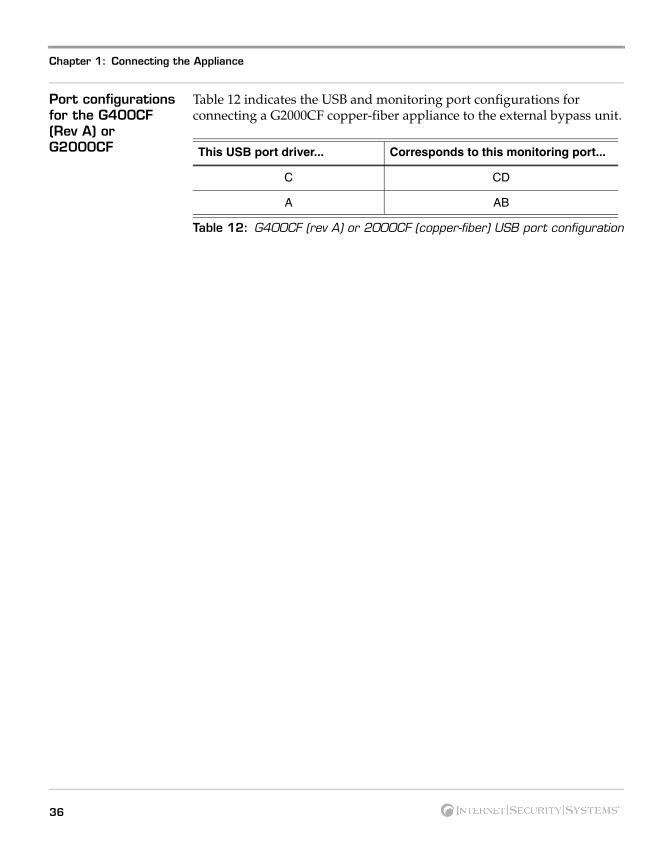
Table 12 indicates the USB and monitoring port configurations for connecting a G2000CF copper-fiber appliance to the external bypass unit.
This USB port driver... Corresponds to this monitoring port...
C CD
A AB
Table 12: G400CF (rev A) or 2000CF (copper-fiber) USB port configuration
36
Chapter 2
Configuring the Appliance
Overview
Introduction This chapter describes how to configure a Proventia G appliance. Use the “Configuration Checklist” on page 38 to gather the information you need to complete the configuration process.
Reference: See the Proventia G Next Generation Installation and Upgrade Procedures Addendum for steps on installing the Next Generation software on an existing legacy G100, G200, G1000 or G1200 model appliance.
In this chapter This chapter contains the following topics:
Topic Page
Configuration Checklist 38
Logging On and Configuring the Appliance 40
Accessing Proventia Manager 45
Managing the Appliance 48
Reinstalling the Appliance 53
Getting Technical Support 53
37Proventia G Intrusion Prevention Appliance Quick Start Guide

Chapter 2: Configuring the Appliance
Configuration Checklist
Required information checklist
Use the checklist in Table 13 to obtain the information you need to configure your Proventia G appliance.
" Setting Description
# Appliance hostname The unique computer name for your appliance
Example: myappliance
Your setting:
# Appliance domain name
The domain suffix for the network
Example: mydomain.com
Your setting:
# Appliance domain name server
This is the IP address of the server you are using to perform domain name lookups (DNS search path). (optional).
Example: 10.0.0.1
Your setting:
# Management Port IP Address
An IP address for the management network adapter.
Your setting:
# Management port subnet mask
The subnet mask value for the network that will connect to your management port.
Your setting:
# Management port default gateway (IP address)
This is the IP address for the management gateway.
Your setting:
# Adapter mode The adapter (operation) mode to use for the appliance. The adapter mode you plan to use should correspond to the way you connected the network cables.
Your setting:
Table 13: Checklist and worksheet for configuration information
38
Configuration Checklist
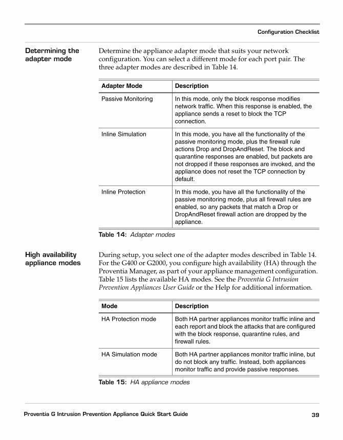
Determining the adapter mode
Determine the appliance adapter mode that suits your network configuration. You can select a different mode for each port pair. The three adapter modes are described in Table 14.
High availability appliance modes
During setup, you select one of the adapter modes described in Table 14. For the G400 or G2000, you configure high availability (HA) through the Proventia Manager, as part of your appliance management configuration. Table 15 lists the available HA modes. See the Proventia G Intrusion Prevention Appliances User Guide or the Help for additional information.
Adapter Mode Description
Passive Monitoring In this mode, only the block response modifies network traffic. When this response is enabled, the appliance sends a reset to block the TCP connection.
Inline Simulation In this mode, you have all the functionality of the passive monitoring mode, plus the firewall rule actions Drop and DropAndReset. The block and quarantine responses are enabled, but packets are not dropped if these responses are invoked, and the appliance does not reset the TCP connection by default.
Inline Protection In this mode, you have all the functionality of the passive monitoring mode, plus all firewall rules are enabled, so any packets that match a Drop or DropAndReset firewall action are dropped by the appliance.
Table 14: Adapter modes
Mode Description
HA Protection mode Both HA partner appliances monitor traffic inline and each report and block the attacks that are configured with the block response, quarantine rules, and firewall rules.
HA Simulation mode Both HA partner appliances monitor traffic inline, but do not block any traffic. Instead, both appliances monitor traffic and provide passive responses.
Table 15: HA appliance modes
39Proventia G Intrusion Prevention Appliance Quick Start Guide
Chapter 2: Configuring the Appliance
Logging On and Configuring the Appliance
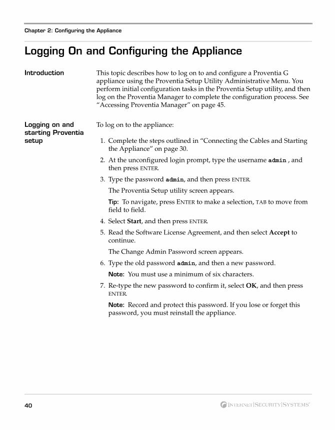
Introduction This topic describes how to log on to and configure a Proventia G appliance using the Proventia Setup Utility Administrative Menu. You perform initial configuration tasks in the Proventia Setup utility, and then log on the Proventia Manager to complete the configuration process. See “Accessing Proventia Manager” on page 45.
Logging on and starting Proventia setup
To log on to the appliance:
1. Complete the steps outlined in “Connecting the Cables and Starting the Appliance” on page 30.
2. At the unconfigured login prompt, type the username admin , and then press ENTER.
3. Type the password admin, and then press ENTER.
The Proventia Setup utility screen appears.
Tip: To navigate, press ENTER to make a selection, TAB to move from field to field.
4. Select Start, and then press ENTER.
5. Read the Software License Agreement, and then select Accept to continue.
The Change Admin Password screen appears.
6. Type the old password admin, and then a new password.
Note: You must use a minimum of six characters.
7. Re-type the new password to confirm it, select OK, and then press ENTER.
Note: Record and protect this password. If you lose or forget this password, you must reinstall the appliance.
40
Logging On and Configuring the Appliance
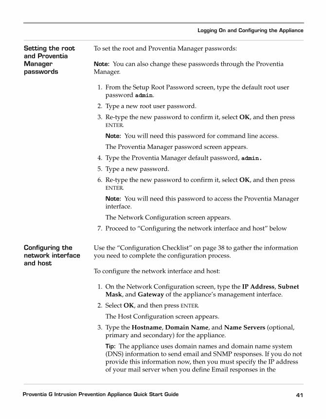
Setting the root and Proventia Manager passwords
To set the root and Proventia Manager passwords:
Note: You can also change these passwords through the Proventia Manager.
1. From the Setup Root Password screen, type the default root user password admin.
2. Type a new root user password.
3. Re-type the new password to confirm it, select OK, and then press ENTER.
Note: You will need this password for command line access.
The Proventia Manager password screen appears.
4. Type the Proventia Manager default password, admin.
5. Type a new password.
6. Re-type the new password to confirm it, select OK, and then press ENTER.
Note: You will need this password to access the Proventia Manager interface.
The Network Configuration screen appears.
7. Proceed to “Configuring the network interface and host” below
Configuring the network interface and host
Use the “Configuration Checklist” on page 38 to gather the information you need to complete the configuration process.
To configure the network interface and host:
1. On the Network Configuration screen, type the IP Address, Subnet Mask, and Gateway of the appliance’s management interface.
2. Select OK, and then press ENTER.
The Host Configuration screen appears.
3. Type the Hostname, Domain Name, and Name Servers (optional, primary and secondary) for the appliance.
Tip: The appliance uses domain names and domain name system (DNS) information to send email and SNMP responses. If you do not provide this information now, then you must specify the IP address of your mail server when you define Email responses in the
41Proventia G Intrusion Prevention Appliance Quick Start Guide
Chapter 2: Configuring the Appliance
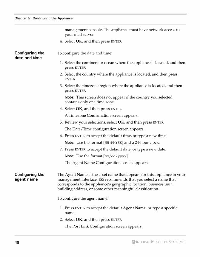
management console. The appliance must have network access to your mail server.
4. Select OK, and then press ENTER.
Configuring the date and time
To configure the date and time:
1. Select the continent or ocean where the appliance is located, and then press ENTER.
2. Select the country where the appliance is located, and then press ENTER.
3. Select the timezone region where the appliance is located, and then press ENTER.
Note: This screen does not appear if the country you selected contains only one time zone.
4. Select OK, and then press ENTER.
A Timezone Confirmation screen appears.
5. Review your selections, select OK, and then press ENTER.
The Date/Time configuration screen appears.
6. Press ENTER to accept the default time, or type a new time.
Note: Use the format [HH:MM:SS] and a 24-hour clock.
7. Press ENTER to accept the default date, or type a new date.
Note: Use the format [mm/dd/yyyy]
The Agent Name Configuration screen appears.
Configuring the agent name
The Agent Name is the asset name that appears for this appliance in your management interface. ISS recommends that you select a name that corresponds to the appliance’s geographic location, business unit, building address, or some other meaningful classification.
To configure the agent name:
1. Press ENTER to accept the default Agent Name, or type a specific name.
2. Select OK, and then press ENTER.
The Port Link Configuration screen appears.
42
Logging On and Configuring the Appliance
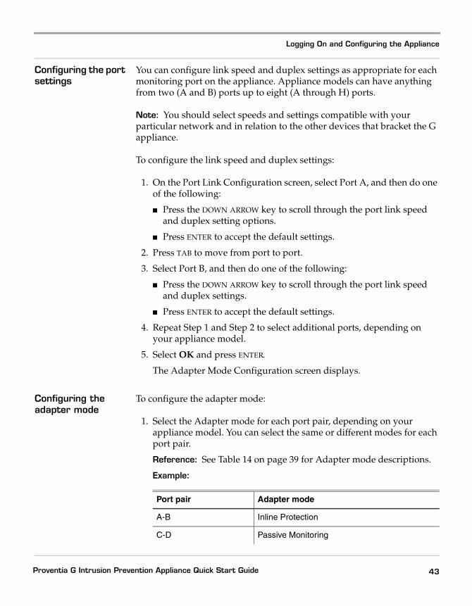
Configuring the port settings
You can configure link speed and duplex settings as appropriate for each monitoring port on the appliance. Appliance models can have anything from two (A and B) ports up to eight (A through H) ports.
Note: You should select speeds and settings compatible with your particular network and in relation to the other devices that bracket the G appliance.
To configure the link speed and duplex settings:
1. On the Port Link Configuration screen, select Port A, and then do one of the following:
� Press the DOWN ARROW key to scroll through the port link speed and duplex setting options.
� Press ENTER to accept the default settings.
2. Press TAB to move from port to port.
3. Select Port B, and then do one of the following:
� Press the DOWN ARROW key to scroll through the port link speed and duplex settings.
� Press ENTER to accept the default settings.
4. Repeat Step 1 and Step 2 to select additional ports, depending on your appliance model.
5. Select OK and press ENTER.
The Adapter Mode Configuration screen displays.
Configuring the adapter mode
To configure the adapter mode:
1. Select the Adapter mode for each port pair, depending on your appliance model. You can select the same or different modes for each port pair.
Reference: See Table 14 on page 39 for Adapter mode descriptions.
Example:
Port pair Adapter mode
A-B Inline Protection
C-D Passive Monitoring
43Proventia G Intrusion Prevention Appliance Quick Start Guide
Chapter 2: Configuring the Appliance
The Adapter Mode Confirmation screen appears.
Caution: When selecting the agent’s adapter mode, you must physically configure the monitored network connection. If is it not configured correctly, the mode setting could have significant network implications.
Reference: Refer to the Appliance Settings chapter of the Proventia G Intrusion Prevention User Guide for more information.
2. Select OK, and then press ENTER.
Applying the settings and logging out
To apply your settings and exit:
1. On the Adapter Mode Configuration screen, press ENTER
A progress bar displays while the appliance applies your settings.
The log out screen displays, indicating that the configuration is complete.
2. Select Logout, and then press ENTER.
E-F Passive Monitoring
G-H Inline Simulation
Port pair Adapter mode
44
Accessing Proventia Manager
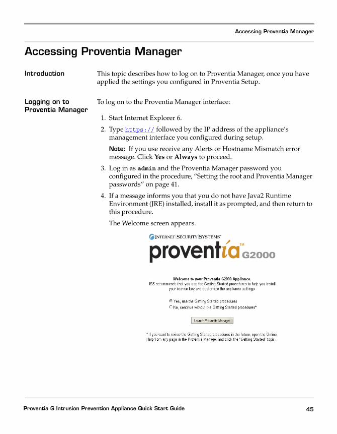
Accessing Proventia Manager
Introduction This topic describes how to log on to Proventia Manager, once you have applied the settings you configured in Proventia Setup.
Logging on to Proventia Manager
To log on to the Proventia Manager interface:
1. Start Internet Explorer 6.
2. Type https:// followed by the IP address of the appliance’s management interface you configured during setup.
Note: If you use receive any Alerts or Hostname Mismatch error message. Click Yes or Always to proceed.
3. Log in as admin and the Proventia Manager password you configured in the procedure, “Setting the root and Proventia Manager passwords” on page 41.
4. If a message informs you that you do not have Java2 Runtime Environment (JRE) installed, install it as prompted, and then return to this procedure.
The Welcome screen appears.
45Proventia G Intrusion Prevention Appliance Quick Start Guide
Chapter 2: Configuring the Appliance
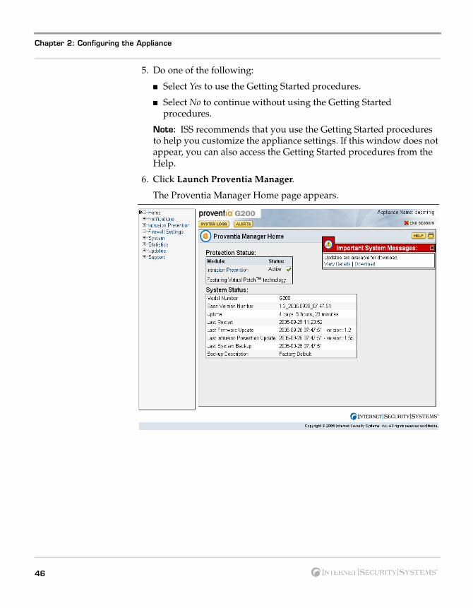
5. Do one of the following:
� Select Yes to use the Getting Started procedures.
� Select No to continue without using the Getting Started procedures.
Note: ISS recommends that you use the Getting Started procedures to help you customize the appliance settings. If this window does not appear, you can also access the Getting Started procedures from the Help.
6. Click Launch Proventia Manager.
The Proventia Manager Home page appears.
46
Accessing Proventia Manager
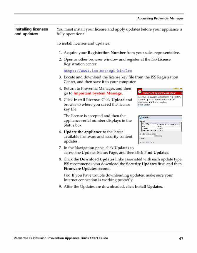
Installing licenses and updates
You must install your license and apply updates before your appliance is fully operational.
To install licenses and updates:
1. Acquire your Registration Number from your sales representative.
2. Open another browser window and register at the ISS License Registration center:
https://www1.iss.net/cgi-bin/lrc
3. Locate and download the license key file from the ISS Registration Center, and then save it to your computer.
4. Return to Proventia Manager, and then go to Important System Message.
5. Click Install License. Click Upload and browse to where you saved the license key file.
The license is accepted and then the appliance serial number displays in the Status box.
6. Update the appliance to the latest available firmware and security content updates.
7. In the Navigation pane, click Updates to access the Updates Status Page, and then click Find Updates.
8. Click the Download Updates links associated with each update type. ISS recommends you download the Security Updates first, and then Firmware Updates second.
Tip: If you have trouble downloading updates, make sure your Internet connection is working properly.
9. After the Updates are downloaded, click Install Updates.
47Proventia G Intrusion Prevention Appliance Quick Start Guide
Chapter 2: Configuring the Appliance
Managing the Appliance
Introduction You can manage the Proventia G appliance locally through the Proventia Manager interface, or you can manage the appliance through SiteProtector, the ISS management console.
For detailed information about configuring appliance management, see The Proventia G Intrusion Prevention Appliances User Guide.
What you manage with Proventia Manager
Proventia Manager is the Web-based local management interface for a single appliance. You can use the Proventia Manager to do the following:
� monitor the appliance status
� configure operation modes
� configure firewall settings
� manage appliance settings and activities, such as updates or event logging
� manage policy inventory
� review alert events.
You can also view appliance statistics and monitor appliance health through the Proventia Manager interface. You also use the Proventia Manager to configure SiteProtector management for your appliance.
What you manage with SiteProtector
With SiteProtector, you can manage components and appliances, monitor events, and schedule reports. By default, your appliance is set up for you to manage it through the Proventia Manager, but if you are managing a group of appliances along with other sensors, you may prefer the centralized management capabilities that SiteProtector provides.
When you register your appliance with SiteProtector, SiteProtector controls the following management functions of the appliance:
� firewall settings
� intrusion prevention settings
� alert events.
48

Managing the Appliance
You can manage update and installation settings in Proventia Manager or in SiteProtector.
Note: When you register the appliance with SiteProtector, some areas of the Proventia Manager become read-only. When you unregister the appliance from SiteProtector, the Proventia Manager become fully functional again.
You manage the following local functions directly on the appliance, even when the appliance is registered with SiteProtector:
� enabling or disabling SiteProtector management
� viewing quarantined intrusions
� deleting quarantine rules.
49Proventia G Intrusion Prevention Appliance Quick Start Guide

Chapter 2: Configuring the Appliance
50
Reinstalling the Appliance
Reinstalling the Appliance
Introduction This topic describes the process for reinstalling the Proventia G Intrusion Prevention Appliances.
Caution: Reinstalling restores the appliance to its original configuration and removes any customized settings.
What you need To reinstall a G appliance, you need the following:
� a computer to use as your configuration interface
� a Proventia G Appliance Recovery CD (model-specific)
� the IP address, subnet mask, and default gateway of the appliance’s management interface.
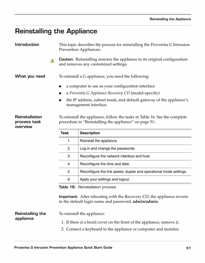
Reinstallation process task overview
To reinstall the appliance, follow the tasks in Table 16. See the complete procedure in “Reinstalling the appliance” on page 51:
Important: After rebooting with the Recovery CD, the appliance reverts to the default login name and password, admin/admin.
Reinstalling the appliance
To reinstall the appliance:
1. If there is a bezel cover on the front of the appliance, remove it.
2. Connect a keyboard to the appliance or computer and monitor.
Task Description
1 Reinstall the appliance.
2 Log in and change the passwords.
3 Reconfigure the network interface and host.
4 Reconfigure the time and date.
5 Reconfigure the link speed, duplex and operational mode settings.
6 Apply your settings and logout.
Table 16: Reinstallation process
51Proventia G Intrusion Prevention Appliance Quick Start Guide
Chapter 2: Configuring the Appliance
Reference: If using a computer, see “Setting up terminal emulation” on page 31.
3. Place your model-specific Proventia G Appliance Recovery CD in the CD-ROM drive.
4. Restart the appliance.
Tip: You can manually turn the power off and on if the appliance is not recognizing the CD .
The appliance restarts
5. At the boot: prompt, type reinstall, and then press ENTER.
The appliance reloads the operating system, displays status messages, ejects the CD, and then reboots.
Important: Promptly remove the CD prior to the appliance restarting.
Wait for the appliance to completely finish the restart process.
6. At the unconfigured login prompt, enter the default username: admin
7. Enter the password, admin.
The Proventia Setup screen displays.
8. Perform the configuration steps as described in “Logging On and Configuring the Appliance” on page 40.
52
Getting Technical Support
Getting Technical Support
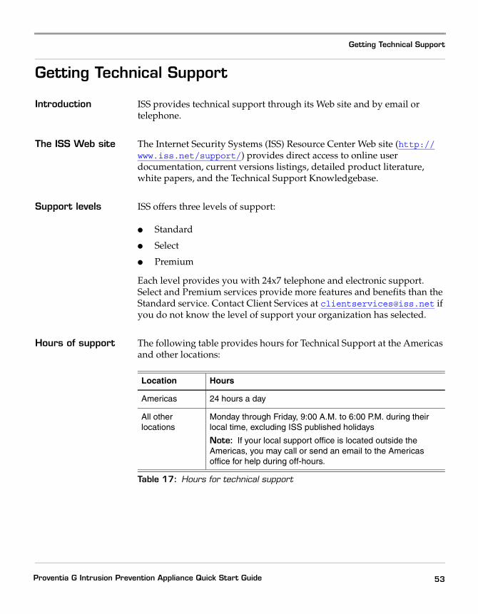
Introduction ISS provides technical support through its Web site and by email or telephone.
The ISS Web site The Internet Security Systems (ISS) Resource Center Web site (http://www.iss.net/support/) provides direct access to online user documentation, current versions listings, detailed product literature, white papers, and the Technical Support Knowledgebase.
Support levels ISS offers three levels of support:
� Standard
� Select
� Premium
Each level provides you with 24x7 telephone and electronic support. Select and Premium services provide more features and benefits than the Standard service. Contact Client Services at [email protected] if you do not know the level of support your organization has selected.
Hours of support The following table provides hours for Technical Support at the Americas and other locations:
Location Hours
Americas 24 hours a day
All other locations
Monday through Friday, 9:00 A.M. to 6:00 P.M. during their local time, excluding ISS published holidays
Note: If your local support office is located outside the Americas, you may call or send an email to the Americas office for help during off-hours.
Table 17: Hours for technical support
53Proventia G Intrusion Prevention Appliance Quick Start Guide
Chapter 2: Configuring the Appliance
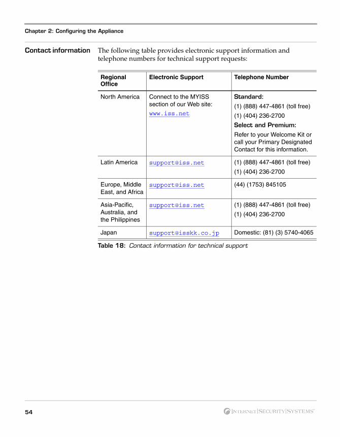
Contact information The following table provides electronic support information and telephone numbers for technical support requests:
Regional Office
Electronic Support Telephone Number
North America Connect to the MYISS section of our Web site:
www.iss.net
Standard:
(1) (888) 447-4861 (toll free)
(1) (404) 236-2700
Select and Premium:
Refer to your Welcome Kit or call your Primary Designated Contact for this information.
Latin America [email protected] (1) (888) 447-4861 (toll free)
(1) (404) 236-2700
Europe, Middle East, and Africa
[email protected] (44) (1753) 845105
Asia-Pacific, Australia, and the Philippines
[email protected] (1) (888) 447-4861 (toll free)
(1) (404) 236-2700
Japan [email protected] Domestic: (81) (3) 5740-4065
Table 18: Contact information for technical support
54

55Proventia G Intrusion Prevention Appliance Quick Start Guide

Chapter 2: Configuring the Appliance
56

Indexdiagram
aAC power 15adapter modes
HA 39non-HA 39
agent name 42appliance
accessing proventia manager 45logging on 40logging out 44
bbypass unit 26
ccabling guidelines 27checklist 38configuring
agent name 42date and time 42link speed and duplex settings 43network interface 41port settings 43
connecting the external bypass unit 25
dDC power 15
Proventia G Intrusion Prevention Appliance Quick Start
G2000F back panel 25G400 back panel 22G400CF (revA) and G2000CF back panel 26G400CF back panel 23G400F (rev A) 25
domain names 41
eemail responses 41
ffault LED 21front panel 12, 20
gG400 (rev A) 22
iinline protection 39inline simulation 39Internet Security Systems
technical support 53Web site 53
57Guide
Index
llicense file
installing 40purchasing 40
logging on and changing the admin password 40
nnetwork cables 30
ppassive monitoring 39passwords 41power connectors 30Proventia setup utility 40
rrack mounting procedures 7reinstalling 51
process 51related publications 8
sserial cable 31setting the root and Proventia Manager
passwords 41setup process 9SNMP responses 41
ttechnical support, Internet Security
Systems 53terminal emulation 31
58
tool-less slide rail kit 7
wWeb site, Internet Security Systems 53