prototype development of a three-wheel riding cultivator ... · yanmar three-wheel riding...
TRANSCRIPT

Introduction
The mechanization rate of upland farming in South
Korea is approximately 58.3% and has increased by more
than 10% over the last decade; however, it is insufficient
compared to the 97.9% mechanization rate of rice farming
that uses rice planting machines and combines. The
mechanization rate of upland farms is higher in larger
farms, but over 85% of upland farms are small farms of
0.3 ha or less. Further, walking farming machinery is used
primarily, apart from tractors used for plowing and land
grading tasks. As such, the rate of riding mechanization
remains under 28.3% (NIAS, 2016). South Korea’s major
upland crops use plastic mulch cultivation primarily to
keep crops warm, conserve moisture, and render weeding
easier. However, the mechanization of the overall task
process is highly limited owing to the increase in the cost
and required manpower caused by plastic mulch cultivation,
as well as difficulties in developing implements for use in
plastic removal, sowing, transplanting, cultivation, fertili-
zation, and harvesting. Most of these tasks are being
Prototype Development of a Three-wheel Riding Cultivator and Its Basic
Performance
Beom Seob Lee1, Soonam Yoo2*, Changhoon Lee2, Il Su Choi3, Yong Choi3, Young Tae Yun3
1Ofe Co. Ltd., Kyoungnam 52007, Republic of Korea2Department of Rural & Bio-systems Engineering, Chonnam National University, Gwangju 61186, Republic of Korea3National Academy of Agricultural Science, Rural Development of Administration, Jeonju 54875, Republic of Korea
Received: September 19th, 2018; Revised: November 21th, 2018; Accepted: November 23th, 2018
Purpose: The aim of this study is to develop a three-wheel riding cultivator for improving the performance of the current
four-wheel riding cultivators in the market. Methods: A prototype three-wheel riding cultivator with the rated power of
15.5-kW, a primary hydrostatic and a two-speed selective gear transmission shifts, front/rear three-wheel drive, a hydraulic
wheel tread adjustment, and the mid-section attachment of the major implements was designed and constructed. Its
specifications and basic performance are investigated. Results: The maximum speeds of the prototype at the low and high
stages were measured to be approximately 7.31, and 11.29 km/h in forward travel, respectively, and approximately 3.60,
and 6.37 km/h in rearward travel, respectively. The minimum ground clearance is shown to be 670 mm. The rotating speeds
of the power takeoff (PTO) shaft at the low and high stages are shown to be approximately 795 and 1,140 rpm, respectively.
The tread of the rear wheels, the minimum radius of turning, and the maximum lifting height of the parallel link device are
measured to be within 1,320–1,720 mm, 2.80 m, and 390 mm, respectively. Approximately 25.3% and 74.7% of the total
weight of the prototype are distributed in the front and rear wheels on flat ground, respectively. When the tread of rear
wheels increased from 1,320 to 1,720 mm, the left and right static lateral overturning angles increased from 33.4° to 39.1°
and from 29.0° to 36.1°, respectively. Conclusions: The prototype three-wheel riding cultivator showed a wide range of
travel and PTO speeds, high minimum ground clearance, small minimum radius of turning, and easy control of the rear
wheel tread. Further, the easy observation of cultivating operations by mid-mounting the implements can improve quality of
work. Therefore, the prototype is expected to contribute to the riding mechanization of cultivating operations for various
upland crops in Korea.
Keywords: Performance, Prototype development, Three-wheel riding cultivator
Original Article Journal of Biosystems Engineering
J. Biosyst. Eng. 43(4):285-295. (2018. 12)https://doi.org/10.5307/JBE.2018.43.4.285
eISSN : 2234-1862 pISSN : 1738-1266
*Corresponding author: Soonam Yoo
Tel: +82-62-530-2155; Fax: +82-62-530-2159
E-mail: [email protected]
Copyright ⓒ 2018 by The Korean Society for Agricultural Machinery
This is an Open Access article distributed under the terms of the Creative Commons Attribution Non-Commercial License (http://creativecommons.org/licenses/by-nc/3.0)
which permits unrestricted non-commercial use, distribution, and reproduction in any medium, provided the original work is properly cited.

Lee et al. Prototype Development of a Three-wheel Riding Cultivator and Its Basic Performance
Journal of Biosystems Engineering • Vol. 43, No. 4, 2018 • www.jbeng.org
286
performed through walking machines. In bean cultivation,
the rate of riding mechanization for each task is 10.4% for
sowing, 23.9% for plastic mulching, 10.7% for pest
control, 0.7% for weeding, 1.5% for reaping, and 0.0% for
topping. These rates are highly limited, and the riding
mechanization is an urgent issue (NIAS, 2016).
Particularly in small-to-mid size farm environments
where it is difficult to use upland crop tractors and
attached implements, it is highly necessary to develop
riding cultivators and attached implements for improving
work efficiency and worker convenience, as well as
reducing cost. In upland crop cultivation, tractors have a
limited ability to perform tasks such as sowing and
transplanting, cultivating and weeding, pest control, fertili-
zation, etc. owing to limitations in ground clearance, and
wheel tread. In South Korea, four-wheel riding cultivators
are being developed and commercialized, but the spread
of the riding cultivators and attached implements has
been extremely slow owing to the machinery’s user-
unfriendliness and performance inadequacies. These
inadequacies cause difficulties in verifying the state of
tasks because most of the machinery is attached at the
back, as well as difficulties in adjusting the wheel tread in
accordance with the variety of cultivation practices that
are used even for a single type of crop in addition to
working limitations such as plastic mulch cultivation. In
Japan, upland farming is moving toward uncovered
cultivation through standardized cultivation practices.
Japan is currently developing and commercializing three-
wheel riding cultivators and attached implements for
upland crops (Minoru, 2005; Yanmar, 2017). This machinery
is suitable for small- to mid-sized farms and provides
work efficiency, work accuracy, and work convenience,
because the operator can see and control the states of
cultivation practices easy by attaching the major imple-
ments to its mid-section, and adjust the wheel tread in
accordance with the variety of cultivation practices by
the hydraulics. In addition to the studies on pest control
implements, none have studied three-wheel riding
cultivators and attached implements that are high in
efficiency and convenience in many tasks, from sowing to
harvesting.
Currently, attempts are performed to spread the
domestic development and commercialization of three-
wheel riding cultivators and attached implements (Choi
et al., 2016 and 2017; Han et al., 2016). In this study, we
designed and built a three-wheel riding cultivator
prototype that can improve the accuracy and convenience
of cultivation tasks through performance improvements
in ground clearance, wheel tread adjustment, and steering,
as well as the improvement in attaching the implements
at the mid-section of the prototype. These improvements
allow it to be used as part of the varying small-scale
upland crop cultivation practices employed in South
Korea to increase the mechanization of upland cultivation
tasks, and for the systematic mechanization of all task
processes. This study provides the primary specifications
of the prototype and evaluates its basic performance.
Materials and Methods
Layout of prototype’s primary arts
The three-wheel riding cultivator includes the following
primary parts. The engine is a 15.5-kW air-cooled four-
stroke gasoline engine. The power transfer unit uses a
constant hydrostatic transmission (HST) as the primary
transmission shift and a two-speed selective gear trans-
mission as the speed range shift, and transmits the motive
power to the front/rear wheel and the implement’s power
takeoff (PTO) axles. The front/rear wheel of the three-
wheel traveling unit is equipped with a front wheel
attachment unit to reduce the turning radius, and allows
the tread of the rear driving wheels to be adjusted using a
hydraulic cylinder to handle various upland crop cultivation
practices. The hydraulic unit provides the precise control
of implements position and steering using hydraulic
devices such as hydraulic cylinders, except for the hydro-
static transmission. The parallel link implement attach-
ment unit improves the precision and convenience of
tasks by allowing for easy observation when major
implements are attached to the three-wheel riding
cultivator’s mid-section. The driving controller unit is for
driving the three-wheel riding cultivator and controlling
the major parts. In addition, the cultivator also includes a
frame, cover, etc.
Prototype’s primary specifications and basic
performance testing
The primary specifications of the three-wheel riding
cultivator prototype that was designed and built in this
study were evaluated and compared with those of Japan’s
Yanmar three-wheel riding cultivator and South Korean’s
four-wheel riding cultivators that are currently in the

Lee et al. Prototype Development of a Three-wheel Riding Cultivator and Its Basic Performance
Journal of Biosystems Engineering • Vol. 43, No. 4, 2018 • www.jbeng.org
287
market. These primary specifications include the body
dimensions and weight, minimum ground clearance,
maximum engine output, front wheel drive type, tire
dimensions, axle and wheel distance, wheel distance
adjustment type, steering type, primary and sub trans-
mission type, number of transmission stages, turning
type and minimum turning radius, PTO type, number of
stages and rotation speed, and the implement attachment
type and control type.
To analyze the basic performance of the three-wheel
riding cultivator prototype, its drive performance was
examined by measuring the traveling speed, straightness,
minimum turning radius, etc. in each transmission stage
at the engine’s rated rotation speed on a concrete test
track at the Department of Agricultural Engineering of
the Rural Development Administration in Jeonbuk Province.
The traveling speed at each transmission stage was
measured on 100 m of flat section by full opening the
governor lever and placing the primary transmission
lever at low speed, medium speed, and high speed when
the sub transmission stage was at low speed and high
speed. The minimum turning radius was measured via
the most exterior tire contact surface mark during left
and right turning. The measurements of the traveling
speed at each transmission stage and the minimum
turning radius were performed three times (FACT,
2016). In addition, the hydraulic cylinder for adjusting
the rear wheel width was operated to measure the
minimum and maximum rear wheel treads and to obtain
the rear wheel adjustment range. The analysis also found
the stage-1 and stage-2 rotation speeds of the mid-section
PTO axle for the operating attached implements at the
engine’s rated rotation speed with no load. Moreover, an
analysis was performed to obtain the lifting range of the
attachment unit’s implement lifting equipment, and to
verify if any lifting malfunctions occurred in the lifting
equipment when attaching three-wheel riding cultivator
implements such as the sowing implement, the cultivating
and weeding implement, the cultivating and hilling
implement, and the topping implement.
To perform a static stability analysis that accounts for
the three-wheel riding cultivator’s pavement gradient,
this study measured its static lateral overturning angle
according to the changes in the real wheel tread, and the
load distribution of the front and rear wheel prototypes
caused by the front/rear gradient, as shown in Figure 1.
The front/rear wheel load distribution was measured by
changing the height of the front wheel from 0 to 25 cm in
5 cm intervals. The static lateral overturning angle was
measured using the overturning angle testing equipment
at the Department of Agricultural Engineering of the
Rural Development Administration using three-wheel
riding cultivator prototype rear wheel widths from 1,330
to 1,725 mm in 80 mm intervals. The static lateral over-
turning angle tests were performed according to the
farming machinery verification standards (FACT, 2016)
by placing a 75 kg sandbag in the driver’s seat, and
measuring the right and left lateral overturning angles of
the test equipment. The line for determining overturning
was set as the line that connects the contact points of the
front wheel and the gradient plane, and the lower rear
wheel and the gradient plane, assuming that the prototype
was turning from the gradient.
Results and Discussion
Layout of Prototype Machine’s Primary Parts
Figure 2 shows the motive power flow diagram for the
three-wheel riding cultivator prototype. It shows the
Figure 1. Views of split of weight on front and rear wheels, and static lateral stability tests.

Lee et al. Prototype Development of a Three-wheel Riding Cultivator and Its Basic Performance
Journal of Biosystems Engineering • Vol. 43, No. 4, 2018 • www.jbeng.org
288
power flow from the engine to the front and rear wheels,
and the implemented mid-section and rear-section PTO
axles. It also shows the driving and PTO axle transmission
control, front wheel quick-turn control, wheel traveling
speed-proportional-type PTO control, and rear wheel
differential lock control.
The prototype’s air-cooled four-stroke gasoline engine
(GX630, Honda, Japan), was measured to exhibit a maximum
output of 15.5 kW / 3,600 rpm. The HST (HVFD21F-R23,
KYB, Japan) contains a pump and motor discharge
volume of 21.5 cm3/rev., maximum pressure of 23 MPa,
and maximum output speed of 0–3,600 rpm.
The prototype machine drives both the front and rear
wheels. The front wheel axle’s driving power passes
through the engine, V-belt drive unit, HST primary trans-
mission, high and low two-stage sub transmission gear
box, front wheel quick-turn chain drive unit and trans-
mission clutch, bevel gear box located on the front wheel,
and the chain gearing unit. The rear wheel axle’s driving
power passes through the engine, V-belt drive unit, HST
primary transmission, high and low two-stage sub trans-
mission gear box, differential unit, and final deceleration
chain drive unit.
The PTO axle for activating the implements and
external power takeoff was installed at two places, i.e., on
the prototype machine’s mid-section and rear-section,
and it allows for driving via the engine and proportional
speed driving via the wheels. The mid-section PTO axle’s
driving power passes through the engine, V-belt drive
unit, HST primary transmission, V-belt drive unit, sub
transmission gear box including a high and low two-stage
PTO transmission, PTO clutch and bevel gear gearing
unit. The rear-section PTO axle installed on the sub
transmission gear box is driven by power that passes
through the engine, V-belt drive unit, HST primary
transmission, V-belt drive unit, and the sub transmission
gear box that includes a high and low two-stage PTO
transmission.
When the engine and rear wheel axle were traveling
forward, the final deceleration ratio was 0.016 during the
sub transmission’s low speed and 0.030 during the sub
transmission’s high speed. The deceleration ratio of the
engine and front wheel axle during forward travel was
the same as the final deceleration ratio of the engine and
rear wheel. However, during turning, the front wheel
attached unit is operated to reduce the turning radius,
and the front wheel’s final deceleration ratio was
calculated as 0.032 and 0.060, which is approximately
twice higher. Therefore, if we ignore the drive wheel’s
slip and the deceleration owing to the HST’s volumetric
efficiency, and consider that the front and rear wheel’s
radii are both approximately 36 cm, the prototype machine’s
theoretical forward travel speed is designed to be within
0–7.8 km/h when the sub transmission is in low speed,
Figure 2. Power flow diagram for the prototype three-wheel riding cultivator.

Lee et al. Prototype Development of a Three-wheel Riding Cultivator and Its Basic Performance
Journal of Biosystems Engineering • Vol. 43, No. 4, 2018 • www.jbeng.org
289
and 0–14.5 km/h when the sub transmission is in high
speed. Similarly, if this is applied to rearward travel, the
theoretical rearward travel speed is 0–4.0 km/h when
the sub transmission is in low speed, and 0–7.5 km/h
when the sub transmission is in high speed.
The final deceleration ratio of the engine and PTO axle
was 0.233 when the PTO transmission was in low speed
and 0.361 when the PTO transmission was in high speed.
Therefore, the theoretical rotation speed of the PTO axis
was calculated to be 838 rpm when the PTO transmission
is in low speed and 1,300 rpm when the PTO trans-
mission is in high speed. In addition, the final deceleration
ratio of the wheels and the speed-proportional PTO axis
was 0.0785 when the sub transmission was in low speed,
and 0.147 when the sub transmission was in high speed.
Considering that the wheel’s final deceleration ratios at
these times were 0.016 and 0.030, respectively, the
speed-proportional PTO’s rotation speed was calculated
as approximately 4.9 turns for every wheel rotation
without regard to the sub transmission stage.
The traveling unit’s front wheel is driven to increase its
traction, and it is equipped with a front wheel quick-turn
unit to perform steering functions and simultaneously
reduce the turning radius such that rapid turning is
possible.
Figure 3 shows the front wheel’s cross section and
exterior. The front wheel drive axle is driven by two bevel
gears and a chain drive units.
Figure 4 shows the front wheel’s steering mechanism.
The steering wheel gear attached to the front wheel’s axle
rotates above the rack gear via a hydraulic cylinder with
a stroke of 95 mm to perform steering, and the maximum
steering angle was set at 80° for the left and right.
Figure 5 shows the front wheel quick-turn apparatus
and its mechanism allows for the automatic change in its
chain gearing sprocket combination if the steering angle
is more than 25°, to increase the front wheel’s rotation
speed by a factor of two and reduce the turning radius. As
shown in the figure, the diamond-shaped link is rotated
by the link connected to the steering mechanism, wire
cable, and spring. This moves the transmission fork and
clutch that are connected to it, and selects a combination
of front wheel chain drive sprockets to drive the front
wheel quick-turn.
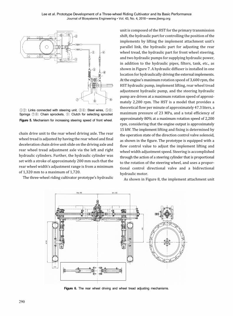
Figure 6 shows the structural diagrams of the rear
wheel power transfer and wheel tread adjustment units.
As shown in the figure, the rear wheel’s driving power is
transferred through the sub transmission gear axle, bevel
and ring gear, differential unit, and final deceleration
Figure 3. Front wheel driving mechanism.
Figure 4. Front wheel steering mechanism.
Lee et al. Prototype Development of a Three-wheel Riding Cultivator and Its Basic Performance
Journal of Biosystems Engineering • Vol. 43, No. 4, 2018 • www.jbeng.org
290
chain drive unit to the rear wheel driving axle. The rear
wheel tread is adjusted by having the rear wheel and final
deceleration chain drive unit slide on the driving axle and
rear wheel tread adjustment axle via the left and right
hydraulic cylinders. Further, the hydraulic cylinder was
set with a stroke of approximately 200 mm such that the
rear wheel width’s adjustment range is from a minimum
of 1,320 mm to a maximum of 1,720.
The three-wheel riding cultivator prototype’s hydraulic
unit is composed of the HST for the primary transmission
shift, the hydraulic part for controlling the position of the
implements by lifting the implement attachment unit’s
parallel link, the hydraulic part for adjusting the rear
wheel tread, the hydraulic part for front wheel steering,
and two hydraulic pumps for supplying hydraulic power,
in addition to the hydraulic pipes, filters, tank, etc., as
shown in Figure 7. A hydraulic diffuser is installed in one
location for hydraulically driving the external implements.
At the engine’s maximum rotation speed of 3,600 rpm, the
HST hydraulic pump, implement lifting, rear wheel tread
adjustment hydraulic pump, and the steering hydraulic
pump are driven at a maximum rotation speed of approxi-
mately 2,200 rpm. The HST is a model that provides a
theoretical flow per minute of approximately 47.3 liters, a
maximum pressure of 23 MPa, and a total efficiency of
approximately 80% at a maximum rotation speed of 2,200
rpm, considering that the engine output is approximately
15 kW. The implement lifting and fixing is determined by
the operation state of the direction control valve solenoid,
as shown in the figure. The prototype is equipped with a
flow control value to adjust the implement lifting and
wheel width adjustment speed. Steering is accomplished
through the action of a steering cylinder that is proportional
to the rotation of the steering wheel, and uses a propor-
tional control directional valve and a bidirectional
hydraulic motor.
As shown in Figure 8, the implement attachment unit
①②: Links connected with steering unit, ③④: Steel wires, ⑤⑥:
Springs ⑦⑧: Chain sprockets, ⑨: Clutch for selecting sprocket
Figure 5. Mechanism for increasing steering speed of front wheel.
Figure 6. The rear wheel driving and wheel tread adjusting mechanisms.

Lee et al. Prototype Development of a Three-wheel Riding Cultivator and Its Basic Performance
Journal of Biosystems Engineering • Vol. 43, No. 4, 2018 • www.jbeng.org
291
uses a parallel link style and consists of the hydraulic
cylinder for implement lifting, vertical parallel link,
implement attachment link. The length of the hydraulic
cylinder for implement lifting can be adjusted to within
290–435 mm. In such a case, the implement lifting range
is approximately 391 mm, and the hitch point’s forward
and backward displacements are approximately 50.4
mm. In the implement attachment unit, an implement
attachment link installed at the end of the parallel link,
and the link is attached to an implement. The implements
are easily attached and detached by simply fastening or
removing the bolts, respectively, on the left and right
sides.
The overall exterior of the three-wheel riding cultivator
prototype is shown in Figure 9. As shown in the figure, the
prototype was designed and built with overall length ´
width ´ height dimensions of 3,280 mm ´ 1,840 mm ´ 1,525
mm when the rear wheel is set to the maximum tread,
Figure 7. Hydraulic circuit for the prototype.
Figure 8. Implements attaching mechanism.

Lee et al. Prototype Development of a Three-wheel Riding Cultivator and Its Basic Performance
Journal of Biosystems Engineering • Vol. 43, No. 4, 2018 • www.jbeng.org
292
excluding any cabin or safety frame.
Primary Specifications of Prototype
Table 1 shows the primary specifications of the three-
wheel riding cultivator prototype that was designed and built.
For the prototype’s transmission, an all-in-one hydraulic
pump and hydraulic motor HST is used as the primary
transmission shift, and a low- and high-speed two-stage
gear transmission is used as the speed range shift. It was
designed to exhibit a forward speed of 0–14.5 km/h and a
backward speed of 0–7.5 km/h. These are the maximum
traveling speeds that are faster than the Japanese Yanmar
three-wheel riding cultivator that is currently in the
market and has an HST primary transmission and a
one-stage gear-style speed range transmission shifts
which exhibit a forward speed of 0–10.2 km/h and a
backward speed of 0–4.8 km/h. When compared to the
South Korean four-wheel riding cultivators with three- to
four-stage constant mesh transmissions and synchromesh
gear style transmissions which exhibit forward speeds of
0–14.3 km/h (Dongyang Moosan Co. Ltd., Korea, K1-C),
0-13.8 km/h (Dongyang Moosan Co. Ltd., Korea, K1-HC),
0-13.8 km/h (Kukje Machinery Co. Ltd., Korea,
KM-2000), 0-11.5 km/h (Asia Technology Co. Ltd., Korea,
CFM-1200), 0-12.6 km/h (Asia Technology Co. Ltd.,
Korea, CFM-1200H), and 0-11.8 km/h (Asia Technology
Co. Ltd., Korea, CFM-1200N), the prototype is almost the
same or faster. As such, it can be used for a variety of
upland crop cultivation tasks (Yanmar, 2017; FACT, 2018).
In South Korea, cultivation practices vary according to
the upland crop and the region; as such, this is a signifi-
Table 1. Specifications of the prototype three-wheel riding cultivator
Item Unit Specifications
Engine
Manufacturer/Model - Honda/GX630
Type - Water cooled, four-stroke, gasoline
Displacement cc 688
Maximum power/speed kW/rpm 15.5/3600
Transmission
Primary shift - HST (assembled hydraulic pump and motor)
Speed range shift - Selective gear type : high, low 2 stages
Theoretical travel speed km/hForward:0–14.5 (high), 0–7.5 (low)
Rearward:0–7.5 (high), 0–4.0 (low)
Travel device
Type - three-wheel driving
Tire dimension - 4.50–19 (outer dia. 720 mm)
Front wheel drive - Gear and chain drive
Rear wheel tread mm 1,320–1,720 (continuously variable)
Front and rear wheel distance mm 2,130
Steering device
Type - Power steering (hydraulic cylinder + wheel and rack gears)
Quick turn - Front wheel speed up
Minimum radius of turning m 2.8
PTO
Number of shafts each 2 (mid and rear)
Clutch type - Tension belt type
Speed stage - 2 (high and low)
Speed rpm 1,300 (high), 838 (low)
Ground PTO - 4.9 rev./1rev. of wheel
Implement hitch
Attaching type - Parallel link type
Implement control - Position control
External hydraulic takeoff each 1
Dimension
Length x width x height mm 3,280 ´ 1,840 ´ 1,525 (without cabin)
Weight kN 8.75
Minimum ground height mm 670
Figure 9. Prototype three-wheel riding cultivator.

Lee et al. Prototype Development of a Three-wheel Riding Cultivator and Its Basic Performance
Journal of Biosystems Engineering • Vol. 43, No. 4, 2018 • www.jbeng.org
293
cant impediment to efficient agricultural mechanization.
Rear wheel tread adjustment is necessary to adapt to
various cultivation practices, and the prototype can
perform the continuously variable adjustment of the rear
wheel tread from 1,320 to 1720 mm through the hydraulic
cylinders. This improves the adaptability and conve-
nience significantly compared to the adjustment methods
of the existing riding cultivators that adjust the wheel
tread by varying the position of the wheels that are
attached to the axle holes.
The prototype’s steering equipment consists of the
hydraulic cylinder, steering wheel, and rack gear. To
reduce the turning radius, it is equipped with a front
wheel attachment unit that turns more quickly and
smoothly than the side clutch methods of the existing
cultivators. The prototype’s minimum turning radius was
2.8 m.
The PTOs for driving the implements are installed at
two places in the mid-section and rear section to drive a
variety of implements, and the transmission operates at
two stages: low and high. Speed proportional PTOs are
installed to perform tasks that are proportional to the
travelling speed such as sowing, etc. The PTO clutch is a
tension belt clutch.
The implement attachment unit is of the parallel link
style. It attaches major implements to the riding
cultivator’s midsection, and controls the position of the
implements through the hydraulic cylinders. An external
hydraulic diffuser is installed at one location to hydrau-
lically drive the implements.
When considering the prototype’s overall size when a
cabin or safety frame is installed, its width and height are
similar to the Yanmar three-wheel riding cultivator, but
the prototype’s length is relatively larger. The weight of
the prototype is 8.75 kN, and its lowest ground clearance
is approximately 670 mm, which is heavier than the 6.40
kN weight of the Yanmar three-wheel riding cultivator
and slightly higher than the 600 mm ground clearance of
the Yanmar (Yanmar, 2017). The lowest ground clearances
of the four-wheel riding cultivators that are currently
being sold in the South Korean market are approximately
490–530 mm, and their weights are within 6.42–9.59 kN
(FACT, 2018). In terms of the lowest ground clearance,
the prototype is the best for upland crop cultivation tasks.
Overall, the prototype was designed and built with
better specifications than the Japanese Yanmar three-
wheel riding cultivator to handle South Korea’s various
upland crops and the cultivation practices that result
from them. Japan is performing significant efforts to
reduce production costs by designing a lightweight body;
further, the prototype’s body must be made lightweight.
It is believed that it will be necessary to simplify the
structure through the field performance testing of the
power transfer unit, steering unit, and PTO equipment to
design and build the prototype to the optimal specifications.
Basic Performance of Prototype
Table 2 shows the average travel speed of the three-
wheel riding cultivator prototype in each transmission
stage at the engine’s rated rotation speed. The maximum
average travel speed when the primary transmission was
in the high-speed stage during forward travel was 7.31
km/h when the speed range transmission shift was at low
speed, and 11.27 km/h when the speed range transmission
shift was at high speed. During backward travel, it was
3.60 km/h when the speed range transmission shift was
at low speed, and 6.37 km/h when the speed range
transmission shift was at high-speed. Its ability to travel
Table 2. Average travel speed of the prototype three-wheel riding cultivator by the stage of transmission
Travel directionStage of
Speed range transmission shift
Stage of
primary transmission shiftAverage travel speed (km/h)
Forward
Low
Low 2.63 (0.04) z
Middle 4.57 (0.04)
High 7.31 (0.25)
High
Low 4.25 (0.14)
Middle 7.16 (0.11)
High 11.27 (0.22)
RearwardLow High 3.60 (0.04)
High High 6.37 (0.14)
zValue in parenthesis means standard deviation.

Lee et al. Prototype Development of a Three-wheel Riding Cultivator and Its Basic Performance
Journal of Biosystems Engineering • Vol. 43, No. 4, 2018 • www.jbeng.org
294
in a straight direction was good. The theoretical-designed
maximum travel speed during forward travel is 7.8 km/h
when the speed range transmission shift is at low speed
and 14.5 km/h when it is at high speed. During backward
travel, it is 4.0 km/h when the speed range transmission
shift is at low speed, and 7.5 km/h when it is at high speed.
Compared to this, the actual travel speed was slightly
reduced. The difference becomes larger when the
transmission stage is at a higher speed. It is believed that
this is because of changes in volume efficiency owing to
friction in the HST primary transmission, and speed
reductions owing to the slip in the drive wheels.
The minimum turning radius during the left and right
turns was approximately 3.45 m when the forward wheel
quick-turn unit was not used and approximately 2.80 m
when it was used. Rear wheel tread adjustment for
adapting to upland crop cultivation practices could be
performed continuously via hydraulic cylinders from
1,320 to 1,720 mm, similar to the range in the target design.
At the engine’s rated rotation speed, the midsection PTO
axle’s rotation speed was approximately 795 at stage 1,
and approximately 1,140 rpm at stage 2. This was
reduced from the design rotation speeds for stages 1 and
2 of 838 and 1,300 rpm, respectively, and this appears to
be due to the volume efficiency changes caused by
friction in the HST. In the results of the tests on the
implement lifting unit, the maximum lifting height was
approximately 390 mm, and it performed without any
malfunctions in tests lifting attached implements such as
a cultivating and weeding implement weighing approximately
2.16 kN.
Table 3 shows the distribution of weight on the front
and rear wheels according to the three-wheel riding
cultivator prototype’s front wheel height. The body’s
overall weight is approximately 8.75 kN; on a flat surface,
this was distributed 25.3% to the front wheel and 74.7%
to the back wheel. However, as the front-rear gradient
was increased, the front wheel weight decreased and the
rear wheel weight increased slightly such that the rear
wheel’s weight distribution ratio increased. Therefore, as
the front-rear gradient increases, the risk of rearward
overturning increases.
Table 4 shows the results of measuring the static
lateral overturning angle according to changes in the rear
wheel tread. As shown in the table, when the rear wheel
tread was adjusted from 1,320 mm to 1,720 mm, the left
lateral overturning angle increased from 33.4° to 39.1°,
and the right lateral overturning angle increased from
29.0° to 36.1°. The lateral overturning angles increased
as the rear width increased, thus implying that increasing
the rear wheel width increases the safety on a sloped
land. A slight difference was shown between the left and
right lateral overturning angles, and this is believed to be
due to the difference in the prototype’s left and right
weight distribution. The left and right lateral overturning
angles of four-wheel riding cultivators being sold in the
South Korean market currently are between 39.9° and
46.0° (FACT, 2018). Compared to this, the prototype’s
safety in regards to lateral overturning is slightly worse
owing to the difference in its structure.
Conclusions
In this study, a three-wheel riding cultivator prototype
was designed and built to increase the riding mechanization
in upland crop cultivation tasks such that the overall task
process was mechanized systematically. The prototype
could achieve improvements in driving performance,
ground clearance, wheel tread adjustment, and steering
performance. By attaching implements to its mid-section,
it provided improvements in task precision, convenience,
and ease of observation. It is believed that this prototype
Table 3. Split of weight on front and rear wheels by the under-propped height of front wheel
Height of front
wheel (cm)
Distribution of mass (kg)
Front wheel Rear wheels
0 226.0 666.0
5 218.5 673.5
10 212.0 680.0
15 203.3 688.7
20 198.3 693.7
25 192.3 699.7
Table 4. Static lateral overturning angle by the tread of rear wheel
Tread of rear wheels
(mm)
Static lateral overturning angle (°)
Left Right
1320 31.4 29.0
1420 34.1 30.9
1520 36.6 33.4
1620 37.4 34.4
1720 39.1 36.1

Lee et al. Prototype Development of a Three-wheel Riding Cultivator and Its Basic Performance
Journal of Biosystems Engineering • Vol. 43, No. 4, 2018 • www.jbeng.org
295
could be used to benefit South Korea’s various upland
crop cultivation practices.
Conflict of Interest
The authors have no conflicting financial or other
interests.
Acknowledgement
This work was performed with the support of the
"Cooperative Research Program for Agriculture Science &
Technology Development (Project No. PJ011807032017)"
The Rural Development Administration, Republic of
Korea.
References
Choi, I. S., S. N. Yoo and B. S. Lee. 2016. Development of a
3-wheeled riding-type cultivator & attaching implements
for upland crops. 2016 Research report for cooperative
research program for agricultural science & technology
development. Project No. PJ011807. Jeonju, Jeonbuk,
Korea: The Rural Development Administration. (In
Korean)
Choi, I. S., S. N. Yoo and B. S. Lee. 2017. Development of a
3-wheeled riding-type cultivator & attaching implements
for upland crops. 2017 Research report for cooperative
research program for agricultural science & technology
development. Project No. PJ011807. Jeonju, Jeonbuk,
Korea: The Rural Development Administration. (In
Korean)
FACT. 2016. Agricultural machinery testing methods –
cultivating vehicle: 209-215. Suwon, Korea The Foundation
of Agriculture Techniques Commercialization and Transfer.
(In Korean)
FACT. 2018. Testing results for 4-wheel riding type cultivating
vehicles. The Foundation of Agriculture Techniques
Commercialization and Transfer. (In Korean)
Han, B. H., I. S. Choi, Y. Choi, Y. T. Yun and S. N. Yoo. 2016.
Design and construction of a 3-wheel riding type
cultivating vehicle. In Proceedings of the KSAM & KSPA
2016 Autumn Conference, pp. 86, Chunan, Chungnam,
Korea: November 2016. (In Korean)
Minoru. 2005. Manual for Minoru 3-wheel cultivating
vehicle RTX30: 1-47. Okayama, Japan: Minoru
Industry Co., Ltd. (In Japanese)
NIAS. 2016. Survey on utilization of agricultural
machinery in 2015: ii, iv-v, 66. Jeonju, Jeonbuk, Korea:
The National Institute of Agricultural Sciences in The
Rural Development Administration. (In Korean)
Yanmar. 2017. Catalog for 3-wheel cultivating vehicle
MD20: 1. Osaka, Japan: Yanmar Co. Ltd. (In Japanese)