proton mission planner's guide mission...proton mission planner's guide
TRANSCRIPT

www.ilslaunch.com
Experience ILS | Achieve Your MissionQuALItY | PErforMAncE | ExPErIEncE | DEDIcAtIon
PROTON LauNch SySTem miSSiON PLaNNeR’S Guide
www.ilslaunch.com
Ref: LKeB-9812-1990, Rev. 7
the technical data included in this document has been cleared for
public release by DoD/office of Security review under case #09-S-2831
and #09-S-3173, on 2 September 2009 and 7 october 2009, respectively.

Revision 7 July 2009
PROTON LAUNCH SYSTEM
MISSION PLANNER’S GUIDE
REVISION NOTICE This document supersedes the Proton Launch System Mission Planner’s Guide - Revision 6, dated December 2004
DISCLOSURE OF DATA LEGEND The technical data included in this document has been cleared for public release by DOD/Office of Security Review under case #09-S-2831 and #09-S-3173, on 2 September 2009 and 7 October 2009, respectively. (Ref: LKEB-9812-1990, Revision 7)
2009 ILS International Launch Services, Inc.
International Launch Services 1875 Explorer Street, Suite 700 Reston, Virginia 20190 USA

Intentionally Blank

Proton Launch System Mission Planner’s Guide, LKEB-9812-1990 Revision 7, July 2009
Cleared for Public Release Through OFOISR Page i
FOREWORD
The Proton Launch System Mission Planner’s Guide is intended to provide information to potential Customers and spacecraft (SC) suppliers, concerning SC design criteria, Baikonur processing facilities, Proton launch capability, available mission analysis and custom engineering support, documentation availability and requirements, and program planning. It is intended to serve as an aid to the planning of future missions but should not be construed as a contractual commitment.
The units of measurement referred to in this document are based on the International System of Units (SI), with English units given in parentheses and all identified dimensions shown should be considered as approximate. In the event that one or more dimensions are critical to a specific payload integration or processing operation, the SC Customer should obtain accurate dimensions from International Launch Services (ILS).
This Guide will be updated periodically. Change pages to this printed document will not be provided, however, the version on the ILS website will be maintained as approved for public release by the U.S. Government. The most current version of this document can be found on the Internet at: http://www.ilslaunch.com.
Users of this guide are encouraged to contact the offices listed below to discuss the Proton Launch Vehicle (LV) family and how the Proton family may meet user needs.
Technical Matters:
Jim Bonner Chief Technical Officer and Vice President Programs and Operations Telephone: +1 (571) 633-7457 Fax: +1 (571) 633-7536 [email protected]
Business Matters:
Wendy Mihalic Vice President, Marketing, Sales and Communications Telephone: +1 (571) 633-7452 Fax: +1 (571) 633-7576 [email protected]
International Launch Services 1875 Explorer Street, Suite 700
Reston, Virginia 20190 USA Telephone: 571.633.7400 Facsimile: 571.633.7535 http://www.ilslaunch.com

Intentionally Blank
Proton Launch System Mission Planner’s Guide, LKEB-9812-1990 Revision 7, July 2009
Cleared for Public Release Through OFOISR Page ii
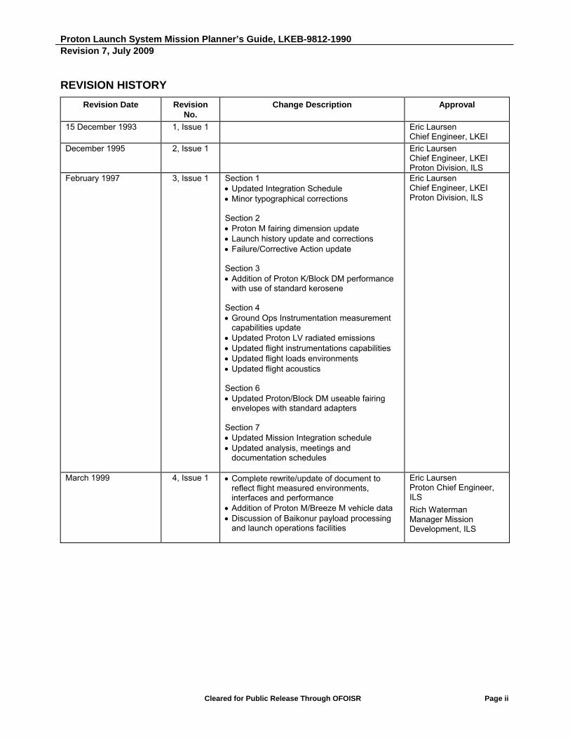
REVISION HISTORY
Revision Date Revision No.
Change Description Approval
15 December 1993 1, Issue 1 Eric Laursen Chief Engineer, LKEI
December 1995 2, Issue 1 Eric Laursen Chief Engineer, LKEI Proton Division, ILS
February 1997 3, Issue 1 Section 1 Updated Integration Schedule Minor typographical corrections Section 2 Proton M fairing dimension update Launch history update and corrections Failure/Corrective Action update Section 3 Addition of Proton K/Block DM performance
with use of standard kerosene Section 4 Ground Ops Instrumentation measurement
capabilities update Updated Proton LV radiated emissions Updated flight instrumentations capabilities Updated flight loads environments Updated flight acoustics Section 6 Updated Proton/Block DM usеable fairing
envelopes with standard adapters Section 7 Updated Mission Integration schedule Updated analysis, meetings and
documentation schedules
Eric Laursen Chief Engineer, LKEI Proton Division, ILS
March 1999 4, Issue 1 Complete rewrite/update of document to reflect flight measured environments, interfaces and performance
Addition of Proton M/Breeze M vehicle data Discussion of Baikonur payload processing
and launch operations facilities
Eric Laursen Proton Chief Engineer, ILS
Rich Waterman Manager Mission Development, ILS

Proton Launch System Mission Planner’s Guide, LKEB-9812-1990 Revision 7, July 2009
Cleared for Public Release Through OFOISR Page iii
REVISION HISTORY (Continued)
Revision Date Revision No.
Change Description Approval
December 2001 5, Issue 1 Complete rewrite/update of document Eric Laursen Chief Engineer, ILS
December 2004 6 Complete rewrite/update of document; deletion of Proton K and Block DM data
Eric Laursen Chief Engineer, ILS
July 2009 7 Updated Proton M/Breeze M vehicle description and performance tables/curves Included Perigee Injection
Supersynchronous Transfer Orbit (SSTO)
Updated transportation and launch induced environments, including low-shock CBOD pyroshock levels
Updated launch facilities descriptions Updated payload adapter (PLA) data in
Appendix D Updated standard payload fairing (PLF)
data and moved from Appendix A.4 and Appendix D to new Appendix E
Clarified standard versus optional mission capabilities and services SSTO performance, Earth escape
performance, etc. moved to new Appendix F
Previous Section 8 data moved to new Appendix F
Updated Quality Management System description (Appendix B)
Removed obsolete data
Jim Bonner, Chief Technical Officer, ILS

Proton Launch System Mission Planner’s Guide, LKEB-9812-1990 Revision 7, July 2009
Cleared for Public Release Through OFOISR Page iv
PREFACE
International Launch Services (ILS) is pleased to offer one of the most capable commercial launch vehicles, and the most comprehensive launch services, available today. The Proton’s services are now available to worldwide Customers at a most competitive price.
ILS is the exclusive marketing agent for commercial sales of the Proton Launch Vehicle (LV) worldwide, and is supported in its operations by full access to the incomparable technological expertise of its partner, Khrunichev State Research and Production Space Center (KhSC). ILS provides customers with a single point of contact for all mission analyses, custom engineering, and launch support tasks involved in using the Proton LV. Both individually and collectively, the members of the ILS team are committed to providing the most cost-effective launch services available in the world - from initial program planning to successful SC launch.

Intentionally Blank

Proton Launch System Mission Planner’s Guide, LKEB-9812-1990 Revision 7, July 2009
Cleared for Public Release Through OFOISR Page v
TABLE OF CONTENTS
FOREWORD ....................................................................................................................................................... I
REVISION HISTORY .......................................................................................................................................... II
PREFACE ......................................................................................................................................................... IV
LIST OF FIGURES ........................................................................................................................................... XI
LIST OF TABLES ............................................................................................................................................ XV
ABBREVIATIONS AND ACRONYMS ......................................................................................................... XVIII
1. INTRODUCTION ........................................................................................................................................ 1-1
1.1 INTERNATIONAL LAUNCH SERVICES: WHO WE ARE ................................................................... 1-2 1.2 RUSSIAN SPACE INDUSTRY CONSOLIDATION .............................................................................. 1-3 1.3 THE QUALITY INITIATIVE: PROVEN COMPREHENSIVE PROGRAM TO IMPROVE PROTON
DESIGN, PRODUCTION AND MANUFACTURING SYSTEMS ............................................................ 1-4 1.4 HISTORY OF PROTON: RUSSA’S PREMIER HEAVY LIFT WORKHORSE .................................... 1-5 1.5 ILS/PROTON: THE TOTAL VALUE SOLUTION ................................................................................. 1-6 1.6 THE PROTON LAUNCH SYSTEM ....................................................................................................... 1-7 1.7 PROTON LAUNCH OPERATIONS: THE BAIKONUR COSMODROME .......................................... 1-10 1.8 ILS LAUNCH SERVICES: WORKING WITH THE ILS TEAM ........................................................... 1-12
2. LV PERFORMANCE .................................................................................................................................. 2-1
2.1 OVERVIEW ........................................................................................................................................... 2-1 2.2 PROTON LAUNCH SYSTEM CAPABILITIES ...................................................................................... 2-1
2.2.1 The Baikonur Launch Site .............................................................................................................. 2-2 2.2.2 Launch Availability .......................................................................................................................... 2-4 2.2.3 Breeze M Upper Stage Capabilities ............................................................................................... 2-4
2.3 PROTON ASCENT PROFILE ............................................................................................................... 2-5 2.3.1 Proton Booster Ascent ................................................................................................................... 2-5 2.3.2 Breeze M Standard Mission Profile .............................................................................................. 2-10 2.3.3 Collision and Contamination Avoidance Maneuver ..................................................................... 2-11
2.4 PERFORMANCE GROUND RULES .................................................................................................. 2-12 2.4.1 Payload Systems Mass Definition ................................................................................................ 2-12 2.4.2 Payload Fairings ........................................................................................................................... 2-17 2.4.3 Mission Analysis Ground Rules ................................................................................................... 2-17 2.4.4 Performance Confidence Levels .................................................................................................. 2-17
2.5 GEOSYNCHRONOUS TRANSFER MISSIONS ................................................................................ 2-18 2.5.1 Launch to GTO/GSO .................................................................................................................... 2-18 2.5.2 Proton M Breeze M Performance ................................................................................................. 2-18
2.6 ORBIT INJECTION ACCURACY ........................................................................................................ 2-27 2.7 SPACECRAFT ORIENTATION AND SEPARATION ......................................................................... 2-27 2.8 LAUNCH VEHICLE TELEMETRY DATA ........................................................................................... 2-29
Proton Launch System Mission Planner’s Guide, LKEB-9812-1990 Revision 7, July 2009
Cleared for Public Release Through OFOISR Page vi
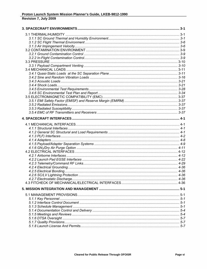
3. SPACECRAFT ENVIRONMENTS ............................................................................................................. 3-1
3.1 THERMAL/HUMIDITY .......................................................................................................................... 3-1 3.1.1 SC Ground Thermal and Humidity Environment ............................................................................ 3-1 3.1.2 SC Flight Thermal Environment ..................................................................................................... 3-6 3.1.3 Air Impingement Velocity ................................................................................................................ 3-6
3.2 CONTAMINATION ENVIRONMENT .................................................................................................... 3-9 3.2.1 Ground Contamination Control ...................................................................................................... 3-9 3.2.2 In-Flight Contamination Control...................................................................................................... 3-9
3.3 PRESSURE ........................................................................................................................................ 3-10 3.3.1 Payload Compartment Venting .................................................................................................... 3-10
3.4 MECHANICAL LOADS ....................................................................................................................... 3-11 3.4.1 Quasi-Static Loads at the SC Separation Plane ......................................................................... 3-11 3.4.2 Sine and Random Vibration Loads .............................................................................................. 3-16 3.4.3 Acoustic Loads ............................................................................................................................. 3-21 3.4.4 Shock Loads ................................................................................................................................. 3-21 3.4.5 Environmental Test Requirements ............................................................................................... 3-28 3.4.6 SC Environmental Test Plan and Report ..................................................................................... 3-34
3.5 ELECTROMAGNETIC COMPATIBILITY (EMC) ................................................................................ 3-37 3.5.1 EMI Safety Factor (EMISF) and Reserve Margin (EMIRM) ......................................................... 3-37 3.5.2 Radiated Emissions ...................................................................................................................... 3-37 3.5.3 Radiated Susceptibility ................................................................................................................. 3-37 3.5.4 EMC of RF Transmitters and Receivers ...................................................................................... 3-37
4. SPACECRAFT INTERFACES ................................................................................................................... 4-1
4.1 MECHANICAL INTERFACES ............................................................................................................... 4-1 4.1.1 Structural Interfaces ....................................................................................................................... 4-1 4.1.2 General SC Structural and Load Requirements ............................................................................ 4-1 4.1.3 PLF) Interfaces ............................................................................................................................... 4-2 4.1.4 Adapters ......................................................................................................................................... 4-8 4.1.5 Payload/Adapter Separation Systems ........................................................................................... 4-9 4.1.6 GN2/Dry Air Purge Option ............................................................................................................ 4-11
4.2 ELECTRICAL INTERFACES .............................................................................................................. 4-12 4.2.1 Airborne Interfaces ....................................................................................................................... 4-12 4.2.2 Launch Pad EGSE Interfaces ...................................................................................................... 4-22 4.2.3 Telemetry/Command RF Links ..................................................................................................... 4-29 4.2.4 Electrical Grounding ..................................................................................................................... 4-36 4.2.5 Electrical Bonding ......................................................................................................................... 4-36 4.2.6 SC/LV Lightning Protection .......................................................................................................... 4-36 4.2.7 Electrostatic Discharge ................................................................................................................. 4-36
4.3 FITCHECK OF MECHANICAL/ELECTRICAL INTERFACES ............................................................ 4-36
5. MISSION INTEGRATION AND MANAGEMENT ...................................................................................... 5-1
5.1 MANAGEMENT PROVISIONS ............................................................................................................. 5-1 5.1.1 Key Personnel ................................................................................................................................ 5-1 5.1.2 Interface Control Document ........................................................................................................... 5-1 5.1.3 Schedule Management .................................................................................................................. 5-1 5.1.4 Documentation Control and Delivery ............................................................................................. 5-4 5.1.5 Meetings and Reviews ................................................................................................................... 5-4 5.1.6 DTSA Oversight ............................................................................................................................. 5-7 5.1.7 Quality Provisions ........................................................................................................................... 5-7 5.1.8 Launch License And Permits.......................................................................................................... 5-7

Proton Launch System Mission Planner’s Guide, LKEB-9812-1990 Revision 7, July 2009
Cleared for Public Release Through OFOISR Page vii
5.2 ILS DELIVERABLES ............................................................................................................................. 5-7 5.2.1 ICD Development ........................................................................................................................... 5-8 5.2.2 Preliminary and Critical Design ...................................................................................................... 5-8 5.2.3 SC Sine Vibration/Acoustic/Fitcheck/Shock Tests Support ......................................................... 5-10 5.2.4 Data Provided After Launch ......................................................................................................... 5-10
5.3 CUSTOMER DELIVERABLES ........................................................................................................... 5-11 5.3.1 ICD Development ......................................................................................................................... 5-12 5.3.2 Preliminary and Critical Design .................................................................................................... 5-12 5.3.3 SC Testing .................................................................................................................................... 5-12 5.3.4 Required Safety Data and Certificates ......................................................................................... 5-13 5.3.5 Launch Campaign and Launch .................................................................................................... 5-13
5.4 SPECIFIC CUSTOMER RESPONSIBILITIES .................................................................................... 5-13 5.4.1 Launch Campaign Duration.......................................................................................................... 5-13 5.4.2 SC and Associated Ground Equipment ....................................................................................... 5-13 5.4.3 Final SC Data ............................................................................................................................... 5-13 5.4.4 SC Readiness .............................................................................................................................. 5-13 5.4.5 Removal of Associated Ground Equipment ................................................................................. 5-14 5.4.6 Evaluation of LV And Associated Services .................................................................................. 5-14 5.4.7 SC Propellants.............................................................................................................................. 5-14 5.4.8 Connectors ................................................................................................................................... 5-14
5.5 ILS SERVICES AND MATERIAL SPECIFICALLY EXCLUDED ........................................................ 5-14
6. SPACECRAFT AND LAUNCH FACILITIES ............................................................................................. 6-1
6.1 FACILITIES OVERVIEW ...................................................................................................................... 6-1 6.1.1 Yubileiny Airfield ............................................................................................................................. 6-1 6.1.2 Building 92A-50 .............................................................................................................................. 6-3 6.1.3 Breeze M Fueling Station (Area 92) ............................................................................................... 6-3 6.1.4 Launch Complexes (Area 81/Area 200) ......................................................................................... 6-3 6.1.5 Hotels ............................................................................................................................................. 6-3
6.2 SC PROCESSING FACILITIES - BUILDING 92A-50 ........................................................................... 6-4 6.2.1 Facility Layout and Area Designations ........................................................................................... 6-4 6.2.2 Receiving/Storage Area - Hall 102 ................................................................................................. 6-6 6.2.3 SC Processing and Fueling Hall - Hall 103A (Room 4101) ........................................................... 6-8 6.2.4 Integration Area - Hall 101 ........................................................................................................... 6-10 6.2.5 Fuel and Oxidizer Conditioning Rooms - Rooms 4112 and 4105 ................................................ 6-12 6.2.6 Fuel and Oxidizer Equipment Decontamination Rooms - Rooms 4111 and 4115 ...................... 6-12 6.2.7 Control Room - Room 4102 ......................................................................................................... 6-13 6.2.8 Entrance/Lobby Area .................................................................................................................... 6-13 6.2.9 Change Room Area ...................................................................................................................... 6-13 6.2.10 Pressurization Airlock - Room 4110 ........................................................................................... 6-15 6.2.11 SCAPE Donning/Doffing Rooms and Showers - Rooms 4108, 4109, 4121 and 4122 .............. 6-15 6.2.12 Clean Storage Hall - Hall 103 ..................................................................................................... 6-15 6.2.13 Ordnance Storage ...................................................................................................................... 6-15 6.2.14 Offices and Conference Room Area - Rooms 1202 through 1209 ............................................ 6-16 6.2.15 LV Processing and Integration Hall - Hall 111 ........................................................................... 6-18
6.3 BREEZE M FUELING FACILITY ........................................................................................................ 6-20 6.4 LAUNCH COMPLEX FACILITIES ...................................................................................................... 6-22
6.4.1 Area 81 Launch Complex ............................................................................................................. 6-22 6.4.2 Area 200 Launch Complex ........................................................................................................... 6-26 6.4.3 Time Countdown .......................................................................................................................... 6-28
Proton Launch System Mission Planner’s Guide, LKEB-9812-1990 Revision 7, July 2009
Cleared for Public Release Through OFOISR Page viii
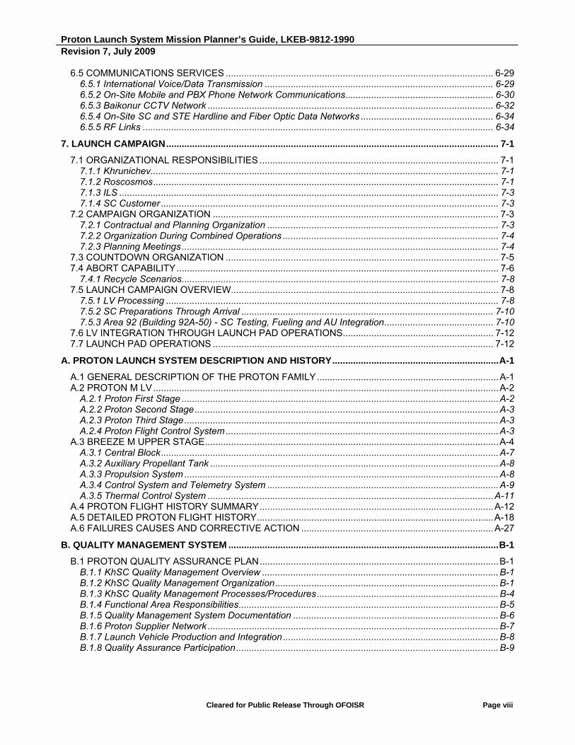
6.5 COMMUNICATIONS SERVICES ....................................................................................................... 6-29 6.5.1 International Voice/Data Transmission ........................................................................................ 6-29 6.5.2 On-Site Mobile and PBX Phone Network Communications ......................................................... 6-30 6.5.3 Baikonur CCTV Network .............................................................................................................. 6-32 6.5.4 On-Site SC and STE Hardline and Fiber Optic Data Networks ................................................... 6-34 6.5.5 RF Links ....................................................................................................................................... 6-34
7. LAUNCH CAMPAIGN ................................................................................................................................ 7-1
7.1 ORGANIZATIONAL RESPONSIBILITIES ............................................................................................ 7-1 7.1.1 Khrunichev ...................................................................................................................................... 7-1 7.1.2 Rosсosmos ..................................................................................................................................... 7-1 7.1.3 ILS .................................................................................................................................................. 7-3 7.1.4 SC Customer .................................................................................................................................. 7-3
7.2 CAMPAIGN ORGANIZATION .............................................................................................................. 7-3 7.2.1 Contractual and Planning Organization ......................................................................................... 7-3 7.2.2 Organization During Combined Operations ................................................................................... 7-4 7.2.3 Planning Meetings .......................................................................................................................... 7-4
7.3 COUNTDOWN ORGANIZATION ......................................................................................................... 7-5 7.4 ABORT CAPABILITY ............................................................................................................................ 7-6
7.4.1 Recycle Scenarios .......................................................................................................................... 7-8 7.5 LAUNCH CAMPAIGN OVERVIEW....................................................................................................... 7-8
7.5.1 LV Processing ................................................................................................................................ 7-8 7.5.2 SC Preparations Through Arrival ................................................................................................. 7-10 7.5.3 Area 92 (Building 92A-50) - SC Testing, Fueling and AU Integration .......................................... 7-10
7.6 LV INTEGRATION THROUGH LAUNCH PAD OPERATIONS .......................................................... 7-12 7.7 LAUNCH PAD OPERATIONS ............................................................................................................ 7-12
A. PROTON LAUNCH SYSTEM DESCRIPTION AND HISTORY ................................................................ A-1
A.1 GENERAL DESCRIPTION OF THE PROTON FAMILY ...................................................................... A-1 A.2 PROTON M LV ..................................................................................................................................... A-2
A.2.1 Proton First Stage .......................................................................................................................... A-2 A.2.2 Proton Second Stage ..................................................................................................................... A-3 A.2.3 Proton Third Stage ......................................................................................................................... A-3 A.2.4 Proton Flight Control System ......................................................................................................... A-3
A.3 BREEZE M UPPER STAGE ................................................................................................................. A-4 A.3.1 Central Block .................................................................................................................................. A-7 A.3.2 Auxiliary Propellant Tank ............................................................................................................... A-8 A.3.3 Propulsion System ......................................................................................................................... A-8 A.3.4 Control System and Telemetry System ......................................................................................... A-9 A.3.5 Thermal Control System .............................................................................................................. A-11
A.4 PROTON FLIGHT HISTORY SUMMARY .......................................................................................... A-12 A.5 DETAILED PROTON FLIGHT HISTORY ........................................................................................... A-18 A.6 FAILURES CAUSES AND CORRECTIVE ACTION .......................................................................... A-27
B. QUALITY MANAGEMENT SYSTEM ........................................................................................................ B-1
B.1 PROTON QUALITY ASSURANCE PLAN ............................................................................................ B-1 B.1.1 KhSC Quality Management Overview ........................................................................................... B-1 B.1.2 KhSC Quality Management Organization ...................................................................................... B-1 B.1.3 KhSC Quality Management Processes/Procedures ...................................................................... B-4 B.1.4 Functional Area Responsibilities .................................................................................................... B-5 B.1.5 Quality Management System Documentation ............................................................................... B-6 B.1.6 Proton Supplier Network ................................................................................................................ B-7 B.1.7 Launch Vehicle Production and Integration ................................................................................... B-8 B.1.8 Quality Assurance Participation ..................................................................................................... B-9

Proton Launch System Mission Planner’s Guide, LKEB-9812-1990 Revision 7, July 2009
Cleared for Public Release Through OFOISR Page ix
B.1.9 Personnel Training ......................................................................................................................... B-9 B.1.10 Quality Parameter Trend Analysis ............................................................................................... B-9 B.1.11 Corrective Action Plans and Continuous Improvement Program .............................................. B-10 B.1.12 Customer Visibility ..................................................................................................................... B-10 B.1.13 Hardware Evolution Design Development Processes ............................................................... B-11 B.1.14 Quality Initiatives ........................................................................................................................ B-13
C. REQUIREMENTS FOR CUSTOMER-SUPPLIED DATA ......................................................................... C-1
C.1 GENERAL INFORMATION .................................................................................................................. C-1 C.2 INPUT DOCUMENTS .......................................................................................................................... C-2 C.3 INTERFACES ....................................................................................................................................... C-3
C.3.1 Mechanical Interfaces .................................................................................................................... C-3 C.3.2 Electrical Interfaces ..................................................................................................................... C-12 C.3.3 Environmental Interfaces ............................................................................................................. C-19 C.3.4 Flight Design ................................................................................................................................ C-20 C.3.5 Operations ................................................................................................................................... C-21
D. ADAPTER SYSTEMS ................................................................................................................................ D-1
D.1 ADAPTER SYSTEM 937VB-1168 ........................................................................................................ D-2 D.1.1 Adapter System Description .......................................................................................................... D-2 D.1.2 Load-Bearing Capability ................................................................................................................ D-8 D.1.3 Interface Ring Characteristics ....................................................................................................... D-8
D.2 ADAPTER SYSTEM 1194VX-1000 (1194VS-1000) ............................................................................ D-9 D.2.1 Adapter System Description .......................................................................................................... D-9 D.2.2 Load-Bearing Capability .............................................................................................................. D-16
D.3 ADAPTER SYSTEM 1666V-1000 ...................................................................................................... D-18 D.3.1 Adapter System Description ........................................................................................................ D-18 D.3.2 Load-Bearing Capability of the Structure ..................................................................................... D-24 D.3.3 Interface Ring Characteristics ..................................................................................................... D-25
D.4 ADAPTER SYSTEM 1664HP-1000 ................................................................................................... D-26 D.4.1 Adapter System Description ........................................................................................................ D-26 D.4.2 Load-Bearing Capability .............................................................................................................. D-31 D.4.3 Interface Ring Characteristics ..................................................................................................... D-31
E. PAYLOAD ENVELOPE ............................................................................................................................. E-1
E.1 PAYLOAD ENVELOPE UNDER FAIRINGS PLF-BR-13305 AND PLF-BR-15255 WITH ADAPTER SYSTEM 937VB-1168 .......................................................................................................... E-2
E.2 PAYLOAD ENVELOPE UNDER FAIRINGS PLF-BR-13305 AND PLF-BR-15255 WITH ADAPTER SYSTEMS 1194VX-1000 AND 1194VS-1000 ..................................................................... E-6
E.3 PAYLOAD ENVELOPE UNDER THE FAIRINGS PLF-BR-13305 AND PLF-BR-15255 WITH ADAPTER SYSTEM 1666V-1000 ........................................................................................................ E-11
E.4 PAYLOAD ENVELOPE UNDER FAIRINGS PLF-BR-13305 AND PLF-BR-15255 ADAPTER SYSTEM 1664HP-1000 ........................................................................................................................ E-15

Proton Launch System Mission Planner’s Guide, LKEB-9812-1990 Revision 7, July 2009
Cleared for Public Release Through OFOISR Page x
F. PROTON LAUNCH SYSTEM OPTIONS AND ENHANCEMENTS .......................................................... F-1
F.1 LEO MISSIONS .................................................................................................................................... F-1 F.2 MEO MISSIONS (INTERMEDIATE CIRCULAR ORBITS) ................................................................... F-1 F.3 HIGHLY ELLIPTICAL ORBITS ............................................................................................................. F-2 F.4 SUPERSYNCHRONOUS TRANSFER ................................................................................................ F-3
F.4.1 PERIGEE INJECTION SUPERSYNCHRONOUS TRANSFER..................................................... F-3 F.4.2 APOGEE INJECTION SUPERSYNCHRONOUS TRANSFER ..................................................... F-8
F.5 EXPRESS GTO MISSION PROFILE ................................................................................................. F-15 F.6 EARTH ESCAPE MISSIONS ............................................................................................................. F-17 F.7 FIVE-METER DIAMETER PAYLOAD FAIRINGS .............................................................................. F-19 F.8 TANDEM LAUNCH SYSTEM ............................................................................................................. F-22 F.9 SHARED LAUNCH WITH THE YAKHTA SC BUS ............................................................................. F-22 F.10 SUMMARY ........................................................................................................................................ F-24

Proton Launch System Mission Planner’s Guide, LKEB-9812-1990 Revision 7, July 2009
Cleared for Public Release Through OFOISR Page xi
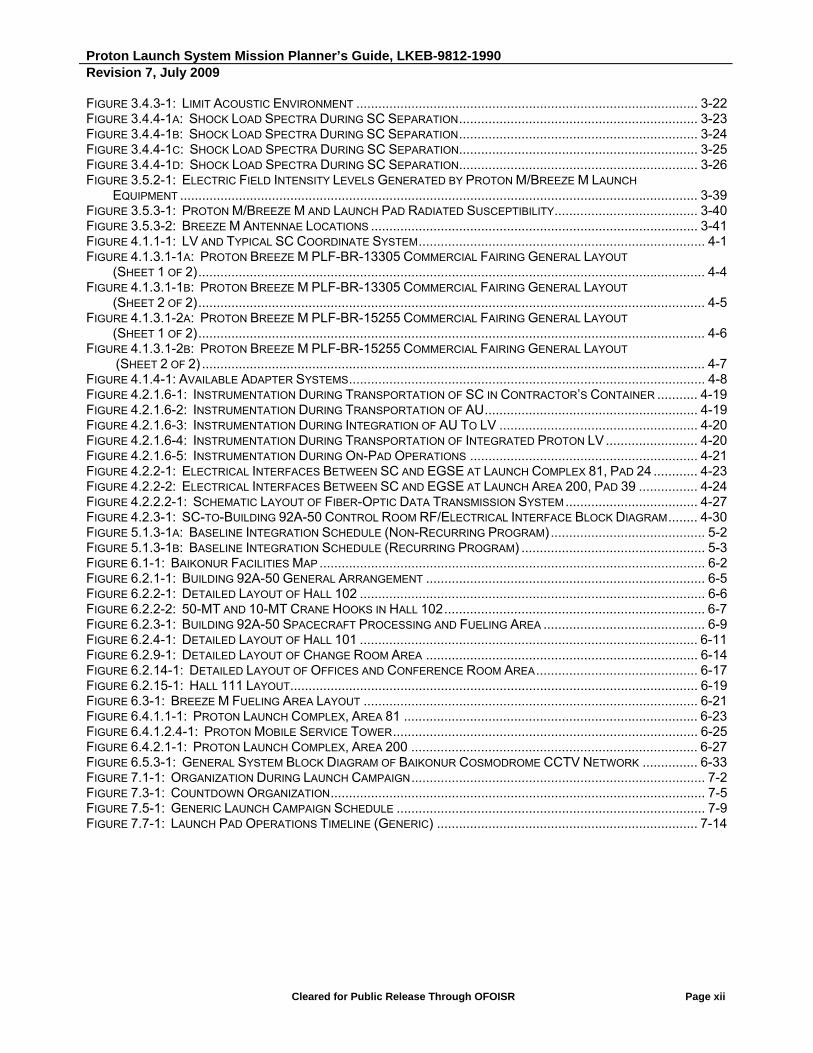
LIST OF FIGURES
FIGURE 1.1: PROTON M BREEZE M LAUNCH ...................................................................................................... 1-1 FIGURE 1.3: PROTON FINAL ASSEMBLY AND TEST AREA .................................................................................... 1-5 FIGURE 1.6-1: PROTON LVS FLIGHT-PROVEN HARDWARE ................................................................................. 1-8 FIGURE 1.6-2: PROTON LVS FLIGHT-PROVEN HARDWARE ................................................................................. 1-9 FIGURE 1.7-1: LOCATION OF BAIKONUR COSMODROME .................................................................................... 1-10 FIGURE 1.7-2: BAIKONUR FACILITIES MAP ....................................................................................................... 1-11 FIGURE 2.2.1-1: THE BAIKONUR LAUNCH SITE SHOWING AVAILABLE PROTON M LV PARKING ORBIT
INCLINATIONS ............................................................................................................................................ 2-3 FIGURE 2.3.1-1: TYPICAL PROTON M LV ASCENT PLUS BREEZE M MAIN ENGINE BURNS .................................... 2-7 FIGURE 2.3.1-2: STANDARD PROTON M LV ASCENT GROUND TRACK AND JETTISON POINTS, AND GROUND
TRACKING STATION ACQUISITION TIMES FOR PROTON M ASCENT ................................................................ 2-8 FIGURE 2.3.1-3: TYPICAL PROTON M LOWER ASCENT ALTITUDE, INERTIAL VELOCITY, LONGITUDINAL
ACCELERATION, AND DYNAMIC PRESSURE .................................................................................................. 2-9 FIGURE 2.3.2-1: TYPICAL 9-HOUR BREEZE M MISSION PROFILE FOR SC INJECTION INTO GTO FROM THE
FIRST ASCENDING NODE OF THE PARKING ORBIT WITH AN INCLINATION OF 51.5 ....................................... 2-13 FIGURE 2.3.2-2: TYPICAL GROUND TRACK OF THE PROTON M BREEZE M FLIGHT FOR SC INJECTION
INTO GTO USING A 9-HOUR MISSION PROFILE FROM THE FIRST ASCENDING NODE OF THE PARKING ORBIT WITH AN INCLINATION OF 51.5 ....................................................................................................... 2-14
FIGURE 2.3.2-3: TYPICAL 7-HOUR BREEZE M MISSION PROFILE FOR SC INJECTION INTO GTO FROM THE FIRST ASCENDING NODE OF THE PARKING ORBIT WITH AN INCLINATION OF 51.5 ....................................... 2-15
FIGURE 2.3.2-4: TYPICAL GROUND TRACK OF THE PROTON M BREEZE M FLIGHT FOR SC INJECTION INTO GTO USING A 7-HOUR MISSION PROFILE FROM THE FIRST ASCENDING NODE OF THE PARKING ORBIT WITH AN INCLINATION OF 51.5 ................................................................................................................. 2-16
FIGURE 2.5.2-1: MASS OF THE PAYLOAD SYSTEM FOR AN OPTIMUM GTO USING A STANDARD 7-HOUR INJECTION FROM THE FIRST ASCENDING NODE OF THE PARKING ORBIT WITH AN INCLINATION OF 51.5 (4 BREEZE M MAIN ENGINE BURNS) ......................................................................................................... 2-19
FIGURE 2.5.2-2: MASS OF THE PAYLOAD SYSTEM FOR AN OPTIMUM GTO USING STANDARD 9-HOUR INJECTION FROM THE FIRST ASCENDING NODE OF THE PARKING ORBIT WITH AN INCLINATION OF 51.5 (5 BREEZE M MAIN ENGINE BURNS) ......................................................................................................... 2-20
FIGURE 2.7-1: SEPARATION AXES DEFINITION ................................................................................................. 2-28 FIGURE 2.8-1: RIGHT ASCENSION AND DECLINATION OF THE +XUS AXIS IN THE EARTH-CENTERED
ABSOLUTE INERTIAL FRAME ..................................................................................................................... 2-33 FIGURE 2.8-2: ORBIT PARAMETERS DEFINITION IN ABSOLUTE OXYZ INERTIAL REFERENCE FRAME ................... 2-34 FIGURE 3.1.1.2-1: FAIRING AIR AND LIQUID THERMAL MODE CONTROL SYSTEMS SCHEMATIC AND
OPERATIONS TIMELINE ............................................................................................................................... 3-5 FIGURE 3.1.1.3-1: SC BATTERY AIR CONDITIONING SYSTEM (OPTION 1) ............................................................ 3-7 FIGURE 3.1.1.3-2: SC BATTERY AIR CONDITIONING SYSTEM (OPTION 2) ............................................................ 3-8 FIGURE 3.3.1-1: NOMINAL PAYLOAD COMPARTMENT INTERNAL PRESSURE CHANGE DURING ASCENT ............... 3-10 FIGURE 3.4.1.1-1: SC TRANSPORTATION IN THE MANUFACTURER'S SC CONTAINER OR IN A KHSC
CONTAINER, AU TRANSPORTATION, AND PROTON-M LV TRANSPORTATION ................................................ 3-12 FIGURE 3.4.1.2-1: LIMIT QUASI-STATIC ACCELERATIONS ON THE SC DURING FLIGHT ........................................ 3-15 FIGURE 3.4.2.1-1: RANDOM VIBRATION LEVELS-GROUND TRANSPORTATION BY RAIL, SC IN CONTAINER
AND SC ATTACHED TO AU ....................................................................................................................... 3-17 FIGURE 3.4.2.1-2: RANDOM VIBRATION LEVELS - ILV GROUND TRANSPORTATION BY RAIL ................................ 3-18 FIGURE 3.4.2.2-1: EQUIVALENT SINE LEVELS AT SC INTERFACE - FLIGHT ENVIRONMENT .................................. 3-20
Proton Launch System Mission Planner’s Guide, LKEB-9812-1990 Revision 7, July 2009
Cleared for Public Release Through OFOISR Page xii
FIGURE 3.4.3-1: LIMIT ACOUSTIC ENVIRONMENT ............................................................................................. 3-22 FIGURE 3.4.4-1A: SHOCK LOAD SPECTRA DURING SC SEPARATION ................................................................. 3-23 FIGURE 3.4.4-1B: SHOCK LOAD SPECTRA DURING SC SEPARATION ................................................................. 3-24 FIGURE 3.4.4-1C: SHOCK LOAD SPECTRA DURING SC SEPARATION ................................................................. 3-25 FIGURE 3.4.4-1D: SHOCK LOAD SPECTRA DURING SC SEPARATION ................................................................. 3-26 FIGURE 3.5.2-1: ELECTRIC FIELD INTENSITY LEVELS GENERATED BY PROTON M/BREEZE M LAUNCH
EQUIPMENT ............................................................................................................................................. 3-39 FIGURE 3.5.3-1: PROTON M/BREEZE M AND LAUNCH PAD RADIATED SUSCEPTIBILITY ....................................... 3-40 FIGURE 3.5.3-2: BREEZE M ANTENNAE LOCATIONS ......................................................................................... 3-41 FIGURE 4.1.1-1: LV AND TYPICAL SC COORDINATE SYSTEM .............................................................................. 4-1 FIGURE 4.1.3.1-1A: PROTON BREEZE M PLF-BR-13305 COMMERCIAL FAIRING GENERAL LAYOUT
(SHEET 1 OF 2) .......................................................................................................................................... 4-4 FIGURE 4.1.3.1-1B: PROTON BREEZE M PLF-BR-13305 COMMERCIAL FAIRING GENERAL LAYOUT
(SHEET 2 OF 2) .......................................................................................................................................... 4-5 FIGURE 4.1.3.1-2A: PROTON BREEZE M PLF-BR-15255 COMMERCIAL FAIRING GENERAL LAYOUT
(SHEET 1 OF 2) .......................................................................................................................................... 4-6 FIGURE 4.1.3.1-2B: PROTON BREEZE M PLF-BR-15255 COMMERCIAL FAIRING GENERAL LAYOUT
(SHEET 2 OF 2) ......................................................................................................................................... 4-7 FIGURE 4.1.4-1: AVAILABLE ADAPTER SYSTEMS ................................................................................................. 4-8 FIGURE 4.2.1.6-1: INSTRUMENTATION DURING TRANSPORTATION OF SC IN CONTRACTOR’S CONTAINER ........... 4-19 FIGURE 4.2.1.6-2: INSTRUMENTATION DURING TRANSPORTATION OF AU .......................................................... 4-19 FIGURE 4.2.1.6-3: INSTRUMENTATION DURING INTEGRATION OF AU TO LV ...................................................... 4-20 FIGURE 4.2.1.6-4: INSTRUMENTATION DURING TRANSPORTATION OF INTEGRATED PROTON LV ......................... 4-20 FIGURE 4.2.1.6-5: INSTRUMENTATION DURING ON-PAD OPERATIONS .............................................................. 4-21 FIGURE 4.2.2-1: ELECTRICAL INTERFACES BETWEEN SC AND EGSE AT LAUNCH COMPLEX 81, PAD 24 ............ 4-23 FIGURE 4.2.2-2: ELECTRICAL INTERFACES BETWEEN SC AND EGSE AT LAUNCH AREA 200, PAD 39 ................ 4-24 FIGURE 4.2.2.2-1: SCHEMATIC LAYOUT OF FIBER-OPTIC DATA TRANSMISSION SYSTEM .................................... 4-27 FIGURE 4.2.3-1: SC-TO-BUILDING 92A-50 CONTROL ROOM RF/ELECTRICAL INTERFACE BLOCK DIAGRAM ........ 4-30 FIGURE 5.1.3-1A: BASELINE INTEGRATION SCHEDULE (NON-RECURRING PROGRAM) .......................................... 5-2 FIGURE 5.1.3-1B: BASELINE INTEGRATION SCHEDULE (RECURRING PROGRAM) .................................................. 5-3 FIGURE 6.1-1: BAIKONUR FACILITIES MAP ......................................................................................................... 6-2 FIGURE 6.2.1-1: BUILDING 92A-50 GENERAL ARRANGEMENT ............................................................................ 6-5 FIGURE 6.2.2-1: DETAILED LAYOUT OF HALL 102 .............................................................................................. 6-6 FIGURE 6.2.2-2: 50-MT AND 10-MT CRANE HOOKS IN HALL 102 ....................................................................... 6-7 FIGURE 6.2.3-1: BUILDING 92A-50 SPACECRAFT PROCESSING AND FUELING AREA ............................................ 6-9 FIGURE 6.2.4-1: DETAILED LAYOUT OF HALL 101 ............................................................................................ 6-11 FIGURE 6.2.9-1: DETAILED LAYOUT OF CHANGE ROOM AREA .......................................................................... 6-14 FIGURE 6.2.14-1: DETAILED LAYOUT OF OFFICES AND CONFERENCE ROOM AREA ............................................ 6-17 FIGURE 6.2.15-1: HALL 111 LAYOUT ............................................................................................................... 6-19 FIGURE 6.3-1: BREEZE M FUELING AREA LAYOUT ........................................................................................... 6-21 FIGURE 6.4.1.1-1: PROTON LAUNCH COMPLEX, AREA 81 ................................................................................ 6-23 FIGURE 6.4.1.2.4-1: PROTON MOBILE SERVICE TOWER ................................................................................... 6-25 FIGURE 6.4.2.1-1: PROTON LAUNCH COMPLEX, AREA 200 .............................................................................. 6-27 FIGURE 6.5.3-1: GENERAL SYSTEM BLOCK DIAGRAM OF BAIKONUR COSMODROME CCTV NETWORK ............... 6-33 FIGURE 7.1-1: ORGANIZATION DURING LAUNCH CAMPAIGN ................................................................................ 7-2 FIGURE 7.3-1: COUNTDOWN ORGANIZATION ...................................................................................................... 7-5 FIGURE 7.5-1: GENERIC LAUNCH CAMPAIGN SCHEDULE .................................................................................... 7-9 FIGURE 7.7-1: LAUNCH PAD OPERATIONS TIMELINE (GENERIC) ....................................................................... 7-14

Proton Launch System Mission Planner’s Guide, LKEB-9812-1990 Revision 7, July 2009
Cleared for Public Release Through OFOISR Page xiii
FIGURE A.3-1: PROTON M/BREEZE M LV MAJOR HARDWARE ELEMENTS ............................................................ A-5 FIGURE A.3-2: GENERAL LAYOUT OF BREEZE M WITH AUXILIARY PROPELLANT TANK .......................................... A-6 FIGURE A.3-3: BREEZE M IN FLIGHT WITH AND WITHOUT AUXILIARY PROPELLANT TANK ...................................... A-7 FIGURE B.1.2-1: MANAGEMENT ORGANIZATION CHART FOR THE KHSC QUALITY MANAGEMENT SYSTEM ............. B-3 FIGURE C.3.1-1: SC PENDULUM MODEL ........................................................................................................... C-8 FIGURE C.3.1-2: SAMPLE SC SLOSH PROPERTIES DURING BALLISTIC FLIGHT AND AT SEPARATION ..................... C-9 FIGURE C.3.1-3: PROPELLANT TANK GEOMETRY REQUIRED DATA ................................................................... C-11 FIGURE D.1.1-1A: ADAPTER SYSTEM 937VB-1168 ............................................................................................ D-3 FIGURE D.1.1-1B: ADAPTER SYSTEM 937VB-1168 ............................................................................................ D-4 FIGURE D.1.1-1C: ADAPTER SYSTEM 937VB-1168 ............................................................................................ D-5 FIGURE D.1.1-1D: ADAPTER SYSTEM 937VB-1168 ............................................................................................ D-6 FIGURE D.1.1-1E: ADAPTER SYSTEM 937VB-1168 ............................................................................................ D-7 FIGURE D.1.3-1: SC AND AS INTERFACE RING CROSS SECTIONS ....................................................................... D-8 FIGURE D.2.1-1A: ADAPTER SYSTEM 1194VX-1000 (1194VS-1000) .............................................................. D-10 FIGURE D.2.1-1B: ADAPTER SYSTEM 1194VX-1000 (1194VS-1000) .............................................................. D-11 FIGURE D.2.1-1C: ADAPTER SYSTEM 1194VX-1000 (1194VS-1000) .............................................................. D-12 FIGURE D.2.1-1D: ADAPTER SYSTEM 1194VX-1000 (1194VS-1000) .............................................................. D-13 FIGURE D.2.1-1E: ADAPTER SYSTEM 1194VX-1000 (1194VS-1000) .............................................................. D-14 FIGURE D.2.1-1F: ADAPTER SYSTEM 1194VX-1000 (1194VS-1000) ............................................................... D-15 FIGURE D.2.2-1: LOAD-BEARING CAPABILITY OF 1194VX-1000 AND 1194VS-1000 ADAPTER SYSTEM ............. D-16 FIGURE D.2.3-1: SC AND AS INTERFACE RING CROSS SECTIONS ..................................................................... D-17 FIGURE D.3.3-1A: ADAPTER SYSTEM 1666V-1000 .......................................................................................... D-19 FIGURE D.3.1-1B: ADAPTER SYSTEM 1666V-1000 .......................................................................................... D-20 FIGURE D.3.1-1C: ADAPTER SYSTEM 1666V-1000 .......................................................................................... D-21 FIGURE D.3.1-1D: ADAPTER SYSTEM 1666V-1000 .......................................................................................... D-22 FIGURE D.3.1-1E: ADAPTER SYSTEM 1666V-1000 .......................................................................................... D-23 FIGURE D.3.2-1: LOAD-BEARING CAPABILITY OF 1666V-1000 ADAPTER SYSTEM .............................................. D-24 FIGURE D.3.3-1: SC AND AS INTERFACE RING CROSS SECTIONS ..................................................................... D-25 FIGURE D.4.1-1A: ADAPTER SYSTEM 1664HP-1000 ........................................................................................ D-27 FIGURE D.4.1-1B: ADAPTER SYSTEM 1664HP-1000 ........................................................................................ D-28 FIGURE D.4.1-1C: ADAPTER SYSTEM 1664HP-1000........................................................................................ D-29 FIGURE D.4.1-1D: ADAPTER SYSTEM 1664HP-1000........................................................................................ D-30 FIGURE E.1-1A: PAYLOAD ENVELOPE UNDER FAIRING PLF-BR-13305 WITH ADAPTER SYSTEM
937VB-1168 ............................................................................................................................................. E-3 FIGURE E.1-1B: PAYLOAD ENVELOPE UNDER FAIRING PLF-BR-15255 WITH ADAPTER SYSTEM
937VB-1168 ............................................................................................................................................. E-4 FIGURE E.1-1C: PAYLOAD ENVELOPE UNDER FAIRINGS PLF-BR-13305 AND PLF-BR-15255 WITH
ADAPTER SYSTEM 937VB-1168 ................................................................................................................ E-5 FIGURE E.2-1A: PAYLOAD ENVELOPE UNDER FAIRING PLF-BR-13305 WITH ADAPTER SYSTEM
1194VX-1000 (1194VS-1000) ................................................................................................................. E-7 FIGURE E.2-1B: PAYLOAD ENVELOPE UNDER FAIRING PLF-BR-15255 WITH ADAPTER SYSTEM
1194VX-1000 (1194VS-1000) ................................................................................................................. E-8 FIGURE E.2-1C: PAYLOAD ENVELOPE UNDER FAIRINGS PLF-BR-13305 AND PLF-BR-15255 WITH
ADAPTER SYSTEM 1194VX-1000 .............................................................................................................. E-9 FIGURE E.2-1D: PAYLOAD ENVELOPE UNDER FAIRINGS PLF-BR-13305 AND PLF-BR-15255 WITH
ADAPTER SYSTEM 1194VS-1000 ............................................................................................................ E-10 FIGURE E.3-1A: PAYLOAD ENVELOPE UNDER FAIRING PLF-BR-13305 WITH ADAPTER SYSTEM
1666V-1000 ........................................................................................................................................... E-12 FIGURE E.3-1B: PAYLOAD ENVELOPE UNDER FAIRING PLF-BR-15255 WITH ADAPTER SYSTEM
1666V-1000 ........................................................................................................................................... E-13 FIGURE E.3-1C: PAYLOAD ENVELOPE UNDER FAIRINGS PLF-BR-13305 AND PLF-BR-15255 WITH
ADAPTER SYSTEM 1666V-1000 ............................................................................................................... E-14

Proton Launch System Mission Planner’s Guide, LKEB-9812-1990 Revision 7, July 2009
Cleared for Public Release Through OFOISR Page xiv
FIGURE E.4-1A: PAYLOAD ENVELOPE UNDER FAIRING PLF-BR-13305 WITH ADAPTER SYSTEM 1664HP-1000 ........................................................................................................................................ E-16
FIGURE E.4-1B: PAYLOAD ENVELOPE UNDER FAIRING PLF-BR-15255 WITH ADAPTER SYSTEM 1664HP-1000 ........................................................................................................................................ E-17
FIGURE E.4-1C: PAYLOAD ENVELOPE UNDER FAIRINGS PLF-BR-13305 AND PLF-BR-15255 WITH ADAPTER SYSTEM 1664HP-1000 ............................................................................................................ E-18
FIGURE F.4.1-1: TYPICAL 4-HOUR BREEZE M FLIGHT FOR SC PERIGEE INJECTION INTO SSTO FROM THE FIRST ASCENDING NODE OF A PARKING ORBIT INCLINED AT 51.5° ............................................................... F-4
FIGURE F.4.1-2: TYPICAL PROTON M/BREEZE M GROUND TRACK FOR SC PERIGEE INJECTION INTO SSTO (HA = 100,000 KM) USING A 4-HOUR TIMELINE FROM THE FIRST ASCENDING NODE OF A PARKING ORBIT
INCLINED AT 51.5 ..................................................................................................................................... F-5 FIGURE 4.1-3: PAYLOAD SYSTEM MASS INJECTED INTO AN OPTIMUM SSTO FROM THE FIRST ASCENDING
NODE OF A PARKING ORBIT INCLINED AT 51.5° (MISSION WITH FOUR BREEZE M BURNS) .............................. F-7 FIGURE F.4.2-1: TYPICAL 15-HOUR BREEZE M MISSION FOR SC APOGEE INJECTION INTO SSTO
(HA = 65,000 KM) FROM THE SECOND DESCENDING NODE OF A PARKING ORBIT INCLINED AT 51.5 .............. F-9 FIGURE F.4.2-2: TYPICAL PROTON M/BREEZE M GROUND TRACK FOR SC APOGEE INJECTION INTO SSTO
(HA = 65000 KM) USING A 15-HOUR TIMELINE FROM THE SECOND DESCENDING NODE OF A PARKING ORBIT INCLINED AT 51.5 ......................................................................................................................... F-10
FIGURE F.4.2-3: MASS OF PAYLOAD SYSTEM INJECTED INTO AN OPTIMUM SSTO (HA = 65,000 KM) USING A 15-HOUR APOGEE INJECTION SCHEME FROM THE SECOND DESCENDING NODE OF THE PARKING ORBIT WITH AN INCLINATION OF 51.5° (MISSION PROFILE WITH FIVE BREEZE M MAIN ENGINE BURNS) .................. F-14
FIGURE F.5-1: BREEZE M TYPICAL INJECTION FOR 4-HOUR EXPRESS MISSION INTO GTO FROM THE FIRST
ASCENDING NODE OF A PARKING ORBIT INCLINED AT 51.5 ....................................................................... F-16 FIGURE F.6-1: PAYLOAD SYSTEM MASS INJECTED BY PROTON M/BREEZE M INTO AN EARTH ESCAPE
TRAJECTORY USING A PARKING ORBIT INCLINED AT 51,5 (MISSION WITH FOUR BREEZE M BURNS) ........... F-18 FIGURE F.7-1A: PAYLOAD ENVELOPE UNDER PROTON BREEZE M 5-METER PLF FAIRING (SHEET 1 OF 2) ......... F-20 FIGURE F.7-1B: PAYLOAD ENVELOPE UNDER PROTON BREEZE M 5-METER PLF FAIRING (SHEET 2 OF 2) ......... F-21 FIGURE F.9-1: LAYOUT OF THE SHARED LAUNCH CONCEPT WITH THE YAKHTA SC BUS ..................................... F-23 FIGURE F.9-2: ALLOWABLE VARIATION IN THE CG OF THE SECOND SC AS A FUNCTION OF THE MASS OF
THE SECOND SC IN A SHARED SC LAUNCH ON THE YAKHTA SC BUS ......................................................... F-24

Proton Launch System Mission Planner’s Guide, LKEB-9812-1990 Revision 7, July 2009
Cleared for Public Release Through OFOISR Page xv
LIST OF TABLES
TABLE 1.6: PROTON LV/SC PLATFORM COMPATIBILITY ..................................................................................... 1-7 TABLE 2.2-1: SUMMARY PROTON M PERFORMANCE (PSM) TO REFERENCE ORBITS ........................................... 2-2 TABLE 2.2.2-1: LAUNCH CONSTRAINTS ............................................................................................................. 2-4 TABLE 2.3.1-1: STANDARD LV ASCENT EVENT TIMES ......................................................................................... 2-6 TABLE 2.5.2-1: PROTON M/BREEZE M PERFORMANCE FOR AN OPTIMUM GTO USING A STANDARD 7-HOUR
INJECTION FROM THE FIRST ASCENDING NODE OF THE PARKING ORBIT WITH AN INCLINATION OF 51.5 (4 BREEZE M MAIN ENGINE BURNS) ......................................................................................................... 2-22
TABLE 2.5.2-2: PROTON M/BREEZE M PERFORMANCE FOR AN OPTIMUM GTO USING A STANDARD 9-HOUR
INJECTION FROM THE FIRST ASCENDING NODE OF THE PARKING ORBIT WITH AN INCLINATION OF 51.5 (5 BREEZE M MAIN ENGINE BURNS) ......................................................................................................... 2-23
TABLE 2.5.2-3: PROTON M/BREEZE M PARAMETRIC PERFORMANCE FOR A NON-OPTIMUM GTO USING A STANDARD 9-HOUR INJECTION FROM THE FIRST ASCENDING NODE OF THE PARKING ORBIT WITH AN
INCLINATION OF 51.5 (5 BREEZE M MAIN ENGINE BURNS) ........................................................................ 2-24 TABLE 2.6-1: BREEZE M UPPER STAGE 3 ORBIT INJECTION ACCURACIES ....................................................... 2-27 TABLE 2.7-1: SC SEPARATION ACCURACIES, LONGITUDINAL SPIN .................................................................... 2-28 TABLE 2.7-2: SC SEPARATION ACCURACIES, TRANSVERSE SPIN ...................................................................... 2-28 TABLE 2.7-3: SC SEPARATION ACCURACIES, THREE-AXIS STABILIZED ............................................................. 2-28 TABLE 2.8-1: FORMAT I - PRELIMINARY ORBIT PARAMETERS ............................................................................ 2-30 TABLE 2.8-2: FORMAT II - BREEZE M ATTITUDE DATA AT SEPARATION .............................................................. 2-31 TABLE 2.8-3: FORMAT III - FINAL SC TARGET ORBIT DATA ............................................................................... 2-32 TABLE 2.8-4: SPACECRAFT-SUPPLIED POST-SEPARATION DATA ...................................................................... 2-35 TABLE 3.1.1-1: AMBIENT TEMPERATURES AT THE BAIKONUR COSMODROME ....................................................... 3-1 TABLE 3.1.1-2: SC THERMAL AND HUMIDITY ENVIRONMENT ............................................................................... 3-2 TABLE 3.1.1.2-1: AU OPERATIONS TIMELINE AT PROCESSING FACILITY AND LAUNCH PAD .................................. 3-4 TABLE 3.2.1-1: GROUND CONTAMINATION ENVIRONMENT .................................................................................. 3-9 TABLE 3.4.1.1-1: QUASI-STATIC SC ACCELERATIONS DURING TRANSPORTATION AND HANDLING
OPERATIONS ........................................................................................................................................... 3-13 TABLE 3.4.1.2-1: LIMIT QUASI-STATIC ACCELERATIONS ON THE SC DURING FLIGHT .......................................... 3-15 TABLE 3.4.4-1: SHOCK LOAD SPECTRA DURING SC SEPARATION .................................................................... 3-27 TABLE 3.4.5-1: TEST REQUIREMENTS SUMMARY ............................................................................................. 3-29 TABLE 3.4.5.1-1: ACOUSTIC TEST REQUIREMENTS .......................................................................................... 3-29 TABLE 3.4.5.3-1: SINE TEST REQUIREMENTS .................................................................................................. 3-31 TABLE 3.4.5.3.1-1: MINIMUM INPUT SIGNAL NOTCHING LEVELS (WITHOUT SAFETY FACTOR) ............................ 3-32 TABLE 3.4.6-1: TYPICAL FORMAT FOR POST-TEST REPORT AND CLA SUMMARY MATRIX ................................. 3-35 TABLE 3.4.6-2: TYPICAL POST-TEST REPORT SINE VIBRATION NOTCHING SUMMARY ........................................ 3-36 TABLE 3.4.6-3: TYPICAL SUMMARY VERIFICATION OF SC FEM BASED ON SINE VIBRATION TEST ....................... 3-36 TABLE 3.5.2-1: PROTON M/BREEZE M RF EQUIPMENT CHARACTERISTICS ....................................................... 3-38 TABLE 4.1.4-1: AVAILABLE PROTON ADAPTER SYSTEMS .................................................................................... 4-8 TABLE 4.1.5-1: MECHANICAL INTERFACE OPTIONS FOR SEPARATION SYSTEM .................................................. 4-10 TABLE 4.1.5-2: PUSH SPRING CHARACTERISTICS ............................................................................................ 4-10 TABLE 4.2.1.5-1: RELAY CLOSURE COMMAND CHARACTERISTICS .................................................................... 4-14 TABLE 4.2.1.6-1: INSTRUMENTATION CHARACTERISTICS AND LOCATIONS FOR GROUND OPERATIONS ................ 4-15

Proton Launch System Mission Planner’s Guide, LKEB-9812-1990 Revision 7, July 2009
Cleared for Public Release Through OFOISR Page xvi
TABLE 4.2.1.6-2: INSTRUMENTATION CHARACTERISTICS AND LOCATIONS FOR FLIGHT EVENTS (TYPICAL) .......... 4-17 TABLE 4.2.2.2-1: CHARACTERISTICS OF FIBER-OPTIC CABLES ......................................................................... 4-28 TABLE 4.2.2.2-2: NUMBERS OF FIBER-OPTIC CABLES ROUTED BETWEEN TECHNICAL COMPLEX AND
LAUNCH COMPLEX FACILITIES .................................................................................................................. 4-28 TABLE 4.2.3-1A: C-BAND RF LINK CHARACTERISTICS ..................................................................................... 4-31 TABLE 4.2.3-1B: KU-BAND RF LINK 1 CHARACTERISTICS ................................................................................. 4-32 TABLE 4.2.3-1C: KU-BAND RF LINK 2 CHARACTERISTICS ................................................................................. 4-33 TABLE 4.2.3-1D: KU-BAND RF LINK 3 CHARACTERISTICS ................................................................................. 4-34 TABLE 4.2.3-1E: KA-BAND RF LINK CHARACTERISTICS .................................................................................... 4-35 TABLE 5.1.5.1-1A: BASELINE MEETING SCHEDULE FOR NON-RECURRING PROGRAM .......................................... 5-5 TABLE 5.1.5.1-1B: BASELINE MEETING SCHEDULE FOR RECURRING PROGRAM .................................................. 5-5 TABLE 5.2-1: ILS DELIVERABLE SCHEDULE FOR A RECURRING AND A NON-RECURRING PROGRAM ...................... 5-8 TABLE 5.2.2-1: DESIGN REVIEW ANALYSES ....................................................................................................... 5-9 TABLE 5.3-1: CUSTOMER DELIVERABLE SCHEDULE FOR A RECURRING AND A NON-RECURRING PROGRAM ........ 5-11 TABLE 6.5.1.1-1: TYPICAL INTERNATIONAL VOICE/DATA TRANSMISSION LINES AVAILABLE TO LAUNCH
CAMPAIGNS ............................................................................................................................................. 6-29 TABLE 6.5.2.1-1: KHSC/ILS-PROVIDED COMMUNICATIONS EQUIPMENT ........................................................... 6-31 TABLE 6.5.4.1-1: ELECTRIC CIRCUIT CHARACTERISTICS OF KHSC PERMANENT CABLES ................................... 6-34 TABLE 6.5.4.2-1: FIBER OPTIC DATA LINKS ..................................................................................................... 6-35 TABLE A.1-1: PROTON M/BREEZE M GENERAL CHARACTERISTICS ..................................................................... A-1 TABLE A.3.3-1: BASIC CHARACTERISTICS OF THE BREEZE M PROPULSION SYSTEM ............................................ A-9 TABLE A.4-1: BREEZE M FLIGHT HISTORY ....................................................................................................... A-13 TABLE A.4-2: PROTON OPERATIONAL LAUNCH RECORD SUMMARY (1970 - 2009) ............................................ A-17 TABLE A.5-1: PROTON OPERATIONAL LAUNCH HISTORY .................................................................................. A-18 TABLE B.1.14-1: LV QUALITY REVIEW BRIEFING — EXAMPLE CONTENTS .......................................................... B-15 TABLE C.3.1-1: SC MASS PROPERTIES ............................................................................................................ C-5 TABLE C.3.1-2: DESCRIPTION OF LIQUID MASSES .............................................................................................. C-6 TABLE C.3.1-3: SC CRITICAL POINTS ................................................................................................................ C-7 TABLE C.3.2-1: SC RF CHARACTERISTICS ...................................................................................................... C-13 TABLE C.3.2-1A: PHASE CENTER LOCATION OF SC T&C ANTENNAS ................................................................ C-14 TABLE C.3.2-2A: J1 UMBILICAL PIN ASSIGNMENTS .......................................................................................... C-15 TABLE C.3.2.2B: J2 UMBILICAL PIN ASSIGNMENTS .......................................................................................... C-17 TABLE C.3.5-1: EGSE DESCRIPTION .............................................................................................................. C-23 TABLE C.3.5-2: FLUIDS/GASES REQUIREMENTS .............................................................................................. C-25 TABLE D.1 PAYLOAD ADAPTER SYSTEMS ........................................................................................................... D-1 TABLE D.1.3-1: CHARACTERISTICS OF SC AND AS INTERFACE RINGS ................................................................. D-8 TABLE D.2.3-1: CHARACTERISTICS OF SC AND AS INTERFACE RINGS ............................................................... D-17 TABLE D.3.3-1: CHARACTERISTICS OF SC AND AS INTERFACE RINGS ............................................................... D-25 TABLE E.1: FAIRINGS AND ADAPTER SYSTEMS DEFINING PAYLOAD ENVELOPES .................................................. E-1 TABLE F.2-1: PROTON M BREEZE M PERFORMANCE TO INTERMEDIATE CIRCULAR ORBITS .................................. F-1 TABLE F.3-1: PROTON M BREEZE M PERFORMANCE TO 24-HOUR ORBITS ......................................................... F-2 TABLE F.4.1-1: PROTON M/BREEZE M PERFORMANCE FOR SC PERIGEE INJECTION INTO SSTO FROM THE
FIRST ASCENDING NODE OF A PARKING ORBIT INCLINED AT 51.5° (MISSION WITH FOUR BREEZE M BURNS) ..................................................................................................................................................... F-6

Proton Launch System Mission Planner’s Guide, LKEB-9812-1990 Revision 7, July 2009
Cleared for Public Release Through OFOISR Page xvii
TABLE F.4.2-1: INJECTION TIME AND COORDINATES OF THE SC SEPARATION POINT FOR APOGEE INJECTION INTO SSTO FROM THE SECOND DESCENDING NODE OF A PARKING ORBIT INCLINED AT 51.5 (MISSION WITH FIVE BREEZE M BURNS) .......................................................................................... F-11
TABLE F.4.2-2: PROTON M BREEZE M PERFORMANCE FOR SC INJECTION INTO OPTIMUM SSTO FROM THE SECOND DESCENDING NODE OF THE PARKING ORBIT WITH AN INCLINATION OF 51.5 (PROFILE WITH FIVE BREEZE M BURNS) .................................................................................................................. F-12
TABLE F.6-1: PROTON M/BREEZE M PERFORMANCE FOR SC LAUNCH INTO AN EARTH ESCAPE TRAJECTORY USING A PARKING ORBIT INCLINED AT 51.5 (MISSION WITH FOUR BREEZE M BURNS) ........... F-17

Intentionally Blank
Proton Launch System Mission Planner’s Guide, LKEB-9812-1990 Revision 7, July 2009
Cleared for Public Release Through OFOISR Page xviii
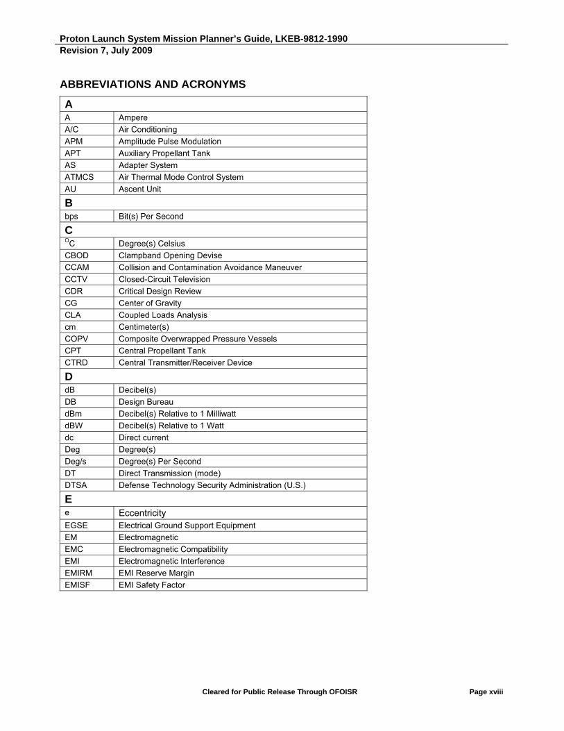
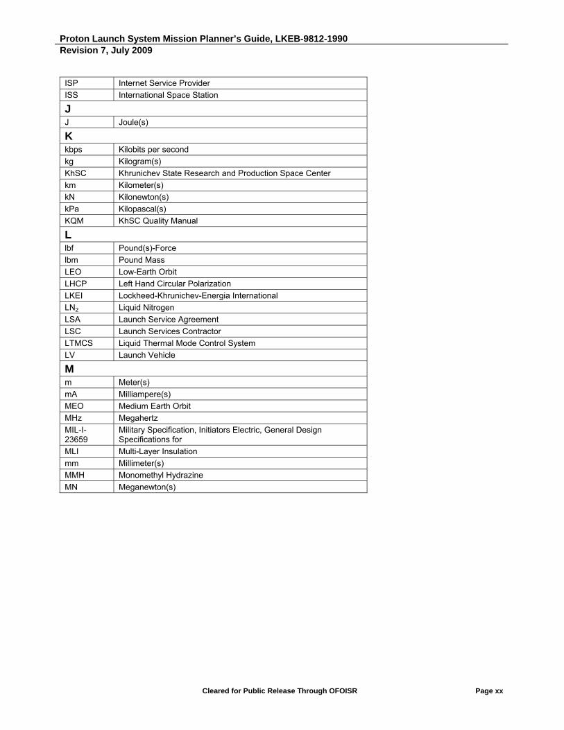
ABBREVIATIONS AND ACRONYMS
A
A Ampere
A/C Air Conditioning
APM Amplitude Pulse Modulation
APT Auxiliary Propellant Tank
AS Adapter System
ATMCS Air Thermal Mode Control System
AU Ascent Unit
B
bps Bit(s) Per Second
C OC Degree(s) Celsius
CBOD Clampband Opening Devise
CCAM Collision and Contamination Avoidance Maneuver
CCTV Closed-Circuit Television
CDR Critical Design Review
CG Center of Gravity
CLA Coupled Loads Analysis
cm Centimeter(s)
COPV Composite Overwrapped Pressure Vessels
CPT Central Propellant Tank
CTRD Central Transmitter/Receiver Device
D
dB Decibel(s)
DB Design Bureau
dBm Decibel(s) Relative to 1 Milliwatt
dBW Decibel(s) Relative to 1 Watt
dc Direct current
Deg Degree(s)
Deg/s Degree(s) Per Second
DT Direct Transmission (mode)
DTSA Defense Technology Security Administration (U.S.)
E
e Eccentricity
EGSE Electrical Ground Support Equipment
EM Electromagnetic
EMC Electromagnetic Compatibility
EMI Electromagnetic Interference
EMIRM EMI Reserve Margin
EMISF EMI Safety Factor

Proton Launch System Mission Planner’s Guide, LKEB-9812-1990 Revision 7, July 2009
Cleared for Public Release Through OFOISR Page xix
F
FEM Finite Element Model
FM Frequency Modulation
FMHF Free Molecular Heat Flux
FODTS Fiber-Optic Data Transmission System
FSA Federal Space Agency/Roscosmos (Russian Federation)
ft Foot; Feet
G
g Gravity or Gram
GEO Geosynchronous Orbit
GHe Gaseous Helium
GHz Gigahertz
GLSTE Ground Launch Support and Test Equipment
GMT Greenwich Mean Time
GN&C Guidance, Navigation, and Control
GN2 Gaseous Nitrogen
GOWG Ground Operations Working Group
GSE Ground Support Equipment
GSO Geostationary Orbit
GTO Geosynchronous Transfer Orbit
H
Ha Apogee Altitude
Hp Perigee Altitude
He Helium
HEO Highly Elliptical Orbit
HEPA High-Efficiency Particulate Air
HERO Hazard of Electromagnetic Radiation to Ordnance
Hg Mercury
hr Hour(s)
HVAC Heating, Ventilation and Air Conditioning
Hz Hertz
I i Inclination
ICD Interface Control Document
IFD In-Flight Disconnect
ILS International Launch Services
IRD Interface Requirements Document
ISDN Integrated Services Digital Network
Proton Launch System Mission Planner’s Guide, LKEB-9812-1990 Revision 7, July 2009
Cleared for Public Release Through OFOISR Page xx
ISP Internet Service Provider
ISS International Space Station
J J Joule(s)
K
kbps Kilobits per second
kg Kilogram(s)
KhSC Khrunichev State Research and Production Space Center
km Kilometer(s)
kN Kilonewton(s)
kPa Kilopascal(s)
KQM KhSC Quality Manual
L
lbf Pound(s)-Force
lbm Pound Mass
LEO Low-Earth Orbit
LHCP Left Hand Circular Polarization
LKEI Lockheed-Khrunichev-Energia International
LN2 Liquid Nitrogen
LSA Launch Service Agreement
LSC Launch Services Contractor
LTMCS Liquid Thermal Mode Control System
LV Launch Vehicle
M
m Meter(s)
mA Milliampere(s)
MEO Medium Earth Orbit
MHz Megahertz
MIL-I-23659
Military Specification, Initiators Electric, General Design Specifications for
MLI Multi-Layer Insulation
mm Millimeter(s)
MMH Monomethyl Hydrazine
MN Meganewton(s)

Proton Launch System Mission Planner’s Guide, LKEB-9812-1990 Revision 7, July 2009
Cleared for Public Release Through OFOISR Page xxi
Mohm Megohm(s)
mohm Milliohm(s)
MOU Memorandum of Understanding
MPa Megapascal(s)
ms Millisecond(s)
m/s Meters Per Second
MST Mobile Service Tower
MT Metric Ton(s)
MUX Multiplexer
V Microvolt(s)
mV Millivolt(s)
N
N Newton(s)
N/A Not Applicable
NASA National Aeronautics and Space Administration (U.S.)
N2H4 Hydrazine
nmi Nautical Mile(s)
N2O4, NTO Nitrogen Tetroxide
NPSK Noise-Like Phase Shift Keying
O
OASPL Overall Sound Pressure Level
OBDC On-Board Digital Computer
OFOISR Office of Freedom of Information and Security Review (U.S.)
OU Orbital Unit
P
Pa Pascal
PBX Private Branch Exchange
PCM Pulse Code Modulation
PDR Preliminary Design Review
PhM Phase Modulation
PLA Payload Adapter
PLCG Proton Launch Campaign Guide

Proton Launch System Mission Planner’s Guide, LKEB-9812-1990 Revision 7, July 2009
Cleared for Public Release Through OFOISR Page xxii
PLE Payload Envelope (or Useable Volume)
PLF Payload Fairing
PM Pulse Modulation
PMPG Proton Mission Planner’s Guide
POP Point of Presence
PPE Personal Protective Equipment
PPF Payload Processing Facility
PSD Power Spectral Density
PSK Phase Shift Keying
PSM Payload Systems Mass
PTRD Peripheral Transmitter/Receiver Device
Q
q Dynamic Pressure
Q Damping Factor
QA Quality Assurance
QMS Quality Management System
QSL Quasi-Static Loads
R
RAAN Right Ascension of the Ascending Node
RF Radio Frequency
RHCP Right Hand Circular Polarization
S
s Second(s)
SC Spacecraft
SCAPE Self-Contained Atmospheric Protective Ensemble
SI International System of Units
SNR Signal-to-Noise Ratio
SOW Statement of Work
SSTO Supersychronous Transfer Orbit
STE System Test Equipment

Proton Launch System Mission Planner’s Guide, LKEB-9812-1990 Revision 7, July 2009
Cleared for Public Release Through OFOISR Page xxiii
T
TBD To Be Determined
TCP/IP Transmission Control Protocol/Internet Protocol
TIM Technical Interchange Meeting
TLM Telemetry
TLS Tandem Launch System
TNT Trinitrotoluene
TV Television
U
UDMH Unsymmetrical Dimethylhydrazine
UPS Uninterruptible Power Supply
UR Universal Rockets
U.S. United States
US Upper Stage - Proton Fourth Stage
V
V Volt(s), Velocity or Vertical
VCR Videocassette Recorder
W
W Watt(s)
W/m2 Watts Per Square Meter
Z
ZERKT Rocket Operations Plant (transliterated)

Proton Launch System Mission Planner’s Guide
SECTION 1
Introduction


Proton Launch System Mission Planner’s Guide, ILSB-9812-1990 Revision 7, July 2009
Cleared for Public Release Through DFOISR Page 1-1
1. INTRODUCTION
The Proton Launch System Mission Planner's Guide (PMPG) is the most comprehensive resource guide available about the Proton Launch Vehicle (LV), the Breeze M Upper Stage (US), and Spacecraft (SC) integration and launch services provided by International Launch Services, Inc. (ILS). Accessible in both electronic and print format, the PMPG allows the user to thoroughly assess the compatibility of the SC payload with the Proton LV system.
The PMPG includes the following planning and technical data:
• Performance and Enhancement data for the Proton LV
• Spacecraft (SC) Environments and Interfaces
• Mission Integration and Management
• Launch Facilities and Campaign
• Quality System
• Customer Data Requirements
• Proton Launch System History
The complete electronic version of the PMPG can be found at www.ilslaunch.com.
Figure 1.1 shows the Proton M Breeze M during launch.
Figure 1.1: Proton M Breeze M Launch
Proton Launch System Mission Planner’s Guide, ILSB-9812-1990 Revision 7, July 2009
Cleared for Public Release Through DFOISR Page 1-2
1.1 INTERNATIONAL LAUNCH SERVICES: WHO WE ARE
International Launch Services, Inc. (ILS) is a U.S.-based company with exclusive rights for worldwide commercial sales and mission management of satellite launches on Russia's premier vehicle, the Proton. ILS is headquartered in Reston, Virginia, a suburb of Washington, D.C. The majority shareholder is Khrunichev State Research and Production Space Center (KhSC) of Moscow. The Proton vehicle launches both commercial ILS missions and Russian government payloads from the Baikonur Cosmodrome, which is operated by the Federal Space Agency (Roscosmos) under lease from the Republic of Kazakhstan. We are a complete launch service organization, committed to long-term relationships with our customers. We are at the customer's side from contract signing through mission completion.
The ILS team has accumulated an extensive experience base, with decades of combined expertise, having launched most commercial satellite platforms and worked with all major satellite operators. This breadth of experience helps ILS keep integration times and launch campaigns short, maintaining a steady launch pace.
Proton launch vehicles are designed and built by KhSC in Moscow, the majority owner of ILS. KhSC is home to all engineering, assembly and test functions for Proton production. And now, with the recent consolidation of Russian space enterprises, KhSC has oversight and control of the majority of all Proton manufacturing from suppliers and manufacturers. The consolidation directly supports Khrunichev’s ongoing efforts for vertical integration of Proton production and the future Angara launch vehicle. Each Proton commercial mission is assigned to a Khrunichev program director who, in partnership with the ILS program director, personally manages each aspect of the mission from kick-off through launch.
ILS and KhSC provide a single source of comprehensive knowledge and support for:
• Mission Design
• Quality Management
• Mission Management
• Proton Manufacturing
• Marketing & Sales
• Integration
• Licensing Support
• Launch Operations

Proton Launch System Mission Planner’s Guide, ILSB-9812-1990 Revision 7, July 2009
Cleared for Public Release Through DFOISR Page 1-3
1.2 RUSSIAN SPACE INDUSTRY CONSOLIDATION
Announced in the summer of 2006 and confirmed by Presidential Decree in February 2007, the first phase of the consolidation of the Russian Space Industry infrastructure is well underway with much of the first phase nearing completion. The consolidation plan is being overseen by Roscosmos, the Federal Space Agency, one of the partners in the International Space Station (ISS) program.
The first phase of the consolidation is scheduled to be complete in 2010, with 8 - 10 organizations merged. The second phase is scheduled to be finalized by 2015 with four remaining core centers: KhSC, RSC Energia, ISS Reshetnev and Progress. Upon completion, 90% of the current 112 Russian space enterprises will be consolidated.
The result of the consolidation is significant for KhSC and ILS. The entities merged under KhSC directly support KhSC’s ongoing efforts for vertical integration of Proton production and the future Angara launch vehicle. This includes the suppliers, subcontractors and manufacturers of all Proton engines ensuring additional streamlining and enhancement of systems, processes and hardware, as well as increased access and production capabilities.
Some of the major space enterprises that have been merged under KhSC to date are:
The Isayev Chemical Engineering Design Bureau (Khimmash) - Khimmash is the leading Russian designer of liquid propellant rocket engines that are used in ILS’s Proton’s Breeze M, Breeze KM for Rokot, and the Fregat upper stages used on Soyuz and Zenit. The Khimmash-made rocket boosters are also used in anti-aircraft rockets, manned spacecraft and space stations.
Voronezh Mechanical Plant (Voronezh) - This mainstay research and production complex has produced aerospace engines since 1940 and began producing rocket engines in 1957. As well, Voronezh has served many of today’s Russian and international space programs with Proton’s 2nd and 3rd stage engines, rocket engines for the Soyuz 3rd stage, Block DM upper stage and ILS’s next generation Angara launch vehicle.
Joint Stock Company Proton-PM (Perm) - KhSC is the major stockholder in Perm, the manufacturer of the 1st stage main engines for Proton since its first launch in 1964. Perm is also the manufacturer of components for aircraft engines and the diagnostics of the gas-turbine electric power supply stations. Perm is also the planned manufacturer of the first stage RD-191 main engines for the next generation Angara launch vehicle.
The Polyot Production Corporation (Polyot, Omsk) - In addition to being the manufacturer and supplier of the Proton first stage riveted modules, Polyot has a long heritage as the single source provider for Russia’s aerospace hardware industry. Its state-of-the-art production facility also produces the multi-purpose booster modules for ILS’s next generation Angara launch vehicle. Polyot’s other product lines include small spacecraft, high-powered engines for military and civilian aircraft and the Kosmos 3M launch vehicle.

Proton Launch System Mission Planner’s Guide, ILSB-9812-1990 Revision 7, July 2009
Cleared for Public Release Through DFOISR Page 1-4
The Design Bureau Khimavtomatika (KBKhA) - On August 7, 2009, the merger of the Design Bureau Khimavtomatika under KhSC was announced after an order was signed by Russian President Dmitry Medvedev to transfer one hundred percent of the federal ownership to KhSC. This merger of the Voronezh-based open joint stock company is another major step in the effort to consolidate the space center industries that contribute to the development of the Proton and future Angara launch systems under KhSC. KBKha is one of the world leaders in the development of liquid rocket engines and major participant in all of the Russian-based manned space flight programs. KBKhA’s liquid rocket engines (LRE) are developed in state of the art production facilities for use in military rockets as well as scientific and commercial launch vehicles. Currently in process is the development of the second and third stage engines for the future Angara vehicle.
Initial results from the consolidation are apparent in terms of the changes associated with Khimmash and Breeze M engine production. Under the direction of the new director general from KhSC, improved facilities and major refurbishment of production lines have allowed a significant increase in the production of the Breeze M engines, with capacity doubled in three years to ten Breeze M engine deliveries in 2008.
KhSC has been in business for over 90 years, supporting a rich heritage in groundbreaking innovation and success in the global space industry. The consolidation of these five key space enterprises not only diversifies the KhSC product offering but also provides a solid foundation for continued growth. The centralization and availability of resources will further ILS’s ability to meet ongoing launch demands and provide schedule assurance for its customers worldwide.
1.3 THE QUALITY INITIATIVE: PROVEN COMPREHENSIVE PROGRAM TO IMPROVE PROTON DESIGN, PRODUCTION AND MANUFACTURING SYSTEMS
In the Spring of 2008, ILS announced a Khrunichev-led top-to-bottom quality assessment and overhaul called the Quality Initiative — a complete review and assessment of Proton design processes and standards, production and management. This top-to- bottom assessment includes immediate and long-term objectives developed to improve Proton and streamline standards across the board.
All of the Quality Initiative activities are designed to provide lasting, long-term benefits in the design, manufacture and launch of Proton vehicles and our approach to quality for years to come.
Working together with our customers, ILS and KhSC are committed to the Quality Initiative’s success and the increased reliability and performance of Proton. We will continue to provide routine updates on the status of our progress as the Quality Initiative evolves. ILS also considers regular reporting of our progress to be crucial to our quality efforts, and we are committed to providing continued insight and transparency to our customers.

Proton Launch System Mission Planner’s Guide, ILSB-9812-1990 Revision 7, July 2009
Cleared for Public Release Through DFOISR Page 1-5
The ILS and KhSC Quality Initiative Program:
New positions at KhSC and ILS that are specifically focused on quality.
Establishing a unified Khrunichev Quality Management System (QMS) across all subsidiaries.
Recertification to the latest international quality standards and continued yearly audits.
Re-evaluation of all factors to improve the launch vehicle design quality.
Enhanced customer visibility into product and process quality.
Factory production is at its highest level in commercial history. Figure 1.3 shows the interior of the Proton final assembly and test area.
Figure 1.3: Proton Final Assembly and Test Area
1.4 HISTORY OF PROTON: RUSSA’S PREMIER HEAVY LIFT WORKHORSE
The Proton has a long and distinguished history, with a record that includes a number of significant firsts.
The first test launch of the original two-stage Proton took place on July 16, 1965, when it was used to launch the four "Proton" satellites for which the launch vehicle was named. Last flown in 1966, the two-stage Proton was succeeded by the three-stage Proton K and four-stage Proton K/Block DM and Proton M/Breeze M launch vehicles.
Since the mid-1960s, Proton has served as the primary heavy-lift launch vehicle for Russian unmanned space programs, orbiting the Salyut series space stations and MIR space station modules, as well as two of the first elements of the International Space Station, the Zvezda and Zarya modules.

Proton Launch System Mission Planner’s Guide, ILSB-9812-1990 Revision 7, July 2009
Cleared for Public Release Through DFOISR Page 1-6
The Proton has launched the Ekran, Express, Raduga and Gorizont series of geostationary communications satellites, Russia's GLONASS navigation satellites and the Zond, Luna, Venera, Mars, Vega, and Phobos interplanetary exploration spacecraft. These missions produced the first samples of the lunar surface to be returned by an unmanned spacecraft, and the first soft landing on the surface of Venus. Its debut as a commercial launch vehicle occurred on April 6, 1996, when Proton injected the Astra 1F satellite into orbit. It also was the first flight under the auspices of ILS.
Utilizing an evolutionary approach, Khrunichev developed a "modernized" version of the Proton — the Proton Breeze M. It provides an increase in performance with the lift capability of over 6 metric tons to Geosynchronous Transfer Orbit (GTO), greater Payload Fairing (PLF) usable volume and increased payload structural capacity. In February of 2009, Proton demonstrated its enhanced lift and performance capabilities with the launch of the dual Express mission. This Proton configuration will be the baseline for all missions beginning in 2010.
The upgraded first stage engines were phased in over a span of three years, while the Breeze M Upper Stage is based on the propulsion system and core module of the Breeze KM unit currently flying on the Rokot lightweight class launch vehicle. The Proton launch vehicle family has become the principal heavy launcher in the Russian space program and one of the premier launch vehicles in the world.
1.5 ILS/PROTON: THE TOTAL VALUE SOLUTION
ILS/Proton has consistently created real value for all of our customers across the globe from major satellite operators, as well as new ventures who are seeking to support their business plans.
Why customers choose ILS/Proton:
High performance vehicle with a flight proven system.
Dedicated launch vehicle.
Proven flight tempo — ILS has launched over 50 commercial missions through July 2009.
Over 340 as of mid-2009 missions launched by Proton since its maiden flight in 1965.
Proton flexibility to meet launch dates is unmatched.
Highly reliable engineering design
Validated launch environments for customer’s SC (e.g., shock, vibration, acoustic and thermal).
Mission design optimization and flexibility.
Multiple launch pads.

Proton Launch System Mission Planner’s Guide, ILSB-9812-1990 Revision 7, July 2009
Cleared for Public Release Through DFOISR Page 1-7
Why customers choose ILS/KhSC:
ILS and KhSC are dedicated to the success of our customers — from contract signing to on-orbit delivery.
Vertically aligned and efficient organization with no conflicting interests.
Experienced commercial launch organization with demonstrated performance.
Full range of quality services from satellite integration to launch.
Mission integration process designed to maximize the production and engineering talents of ILS/KhSC team.
Streamlined production systems with KhSC having direct control over the majority of all suppliers and manufacturers for Proton due to Russian Space Industry Consolidation.
Robust hardware production in the factory ensuring flexibility and reliability.
ILS Europe office created to enhance our level of service and availability across Europe.
1.6 THE PROTON LAUNCH SYSTEM
The Proton Breeze M has more than 6 metric tons of lift capability to GTO with precise delivery to orbit. Proton launch performance is discussed in detail in Section 2 and Appendix F. Because of its compatibility with all major SC platforms (see Table 1.6) the Proton Breeze M has the flexibility for geosynchronous and Supersynchronous Transfer (SST), highly elliptical and direct geostationary insertion missions. The Proton Breeze M has a long heritage of solid performance with over 40 years of experience and over 340 flights since mid-2009.
Table 1.6: Proton LV/SC Platform Compatibility
Satellite Bus Compatible Launched
601
702
A2100
E2000/3000
LS-1300
SB3000/4000
Star2
DS2000
Express
ILS and KhSC have adopted a common nomenclature to identify various components of the Proton Breeze M configuration. These terms are used throughout this PMPG and are summarized in Figures 1.6-1 and 1.6-2.
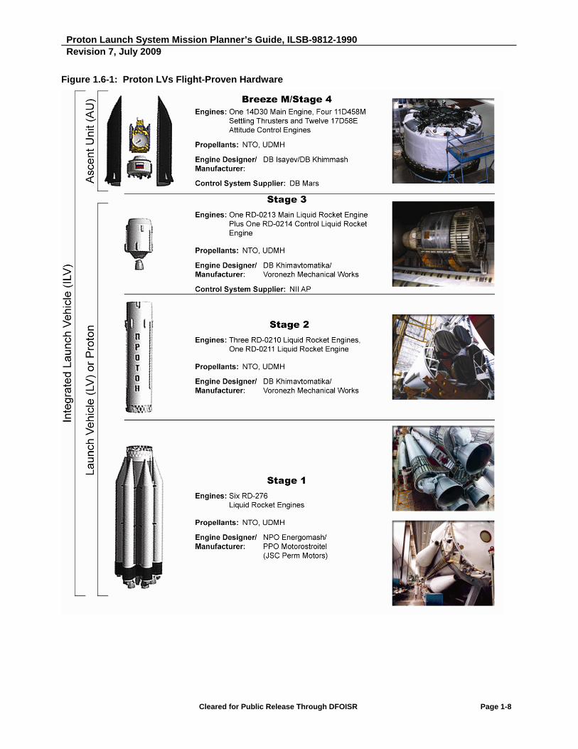
Proton Launch System Mission Planner’s Guide, ILSB-9812-1990 Revision 7, July 2009
Cleared for Public Release Through DFOISR Page 1-8
Figure 1.6-1: Proton LVs Flight-Proven Hardware

Proton Launch System Mission Planner’s Guide, ILSB-9812-1990 Revision 7, July 2009
Cleared for Public Release Through DFOISR Page 1-9
Figure 1.6-2: Proton LVs Flight-Proven Hardware

Proton Launch System Mission Planner’s Guide, ILSB-9812-1990 Revision 7, July 2009
Cleared for Public Release Through DFOISR Page 1-10
1.7 PROTON LAUNCH OPERATIONS: THE BAIKONUR COSMODROME
The Baikonur Cosmodrome is one of the Russian Federation’s two major space launch complexes. As shown in Figure 1.7-1, Baikonur is located in the Republic of Kazakhstan approximately 2100 kilometers from Moscow. Baikonur has been the launch site for Soviet, and later Russian, human spaceflight programs, geostationary satellites and scientific missions to the moon and planets. It is also the site of the first launch of a satellite (Sputnik 1 on October 4, 1957) and the first human into space (Yuri Gagarin in April 12, 1961). The earliest achievements in space exploration have been made at historic Baikonur.
Figure 1.7-1: Location of Baikonur Cosmodrome
Baikonur is a large Y-shaped complex, shown in Figure 1.7-2, that extends about 160 kilometers (100 miles) east to west and 88 kilometers (55 miles) north to south. The vehicle processing and launch areas are connected to each other and to the city of Baikonur by 470 kilometers (290 miles) of wide-gauge railroad lines. The rail system is the principal mode of transportation. Rockets are carried from their vehicle assembly buildings to their launch pads horizontally on railcars and erected onto the launch pad.

Proton Launch System Mission Planner’s Guide, ILSB-9812-1990 Revision 7, July 2009
Cleared for Public Release Through DFOISR Page 1-11
Figure 1.7-2: Baikonur Facilities Map
The SC is transported to the Baikonur Cosmodrome by air and is offloaded at the on-site Yubileiny Airfield. It is then transported to the state-of the-art processing facility in Area 92 for testing, fueling, mating to the Breeze M Upper Stage and encapsulation with the payload fairing.
Weather conditions in Baikonur have very few launch restraints, offering additional schedule assurance for customers.
Two launch pads are available for commercial missions.
Launch vehicle and SC time on pad is five days.

Proton Launch System Mission Planner’s Guide, ILSB-9812-1990 Revision 7, July 2009
Cleared for Public Release Through DFOISR Page 1-12
1.8 ILS LAUNCH SERVICES: WORKING WITH THE ILS TEAM
At ILS, we take great care and pride in the relationships that are fostered with our customers. With ILS and KhSC, customers receive, and have full access to, a wide range of launch services through ILS’s dedicated account team. The account team is designed to provide the most focused attention and highest quality services to each customer led by a single source of contact throughout the life of the program, primarily, the account executive. Team members specialize in the areas of sales and marketing, program management/technical operations, contracts and finance and licensing/government compliance. The account team works with each customer to identify the optimal launch solution for their business and program objective and tirelessly guide the process from initial marketing consultations through launch and post-flight activities.
The ILS Team:
The account executive is the customer’s voice within the ILS organization and has direct access to both ILS and KhSC senior management.
The sales and marketing team provide coordinated support for the launch viewing event in Baikonur and all publicity and marketing collateral associated with the campaign.
The business and finance team member assists the customer with all contractual, insurance and financing matters.
Program and launch operations management is led by the program director who provides technical advice, development and control of the mission-specific Interface Control Document (ICD), managing the necessary resources for the launch mission, and acting as liaison between the suppliers, manufacturers and subcontractors to the launch campaign effort.
- Working with the ILS program director, a dedicated KhSC program director and team is assigned to each customer mission. This team ensures that all customer needs are met from program inception through post-launch activities and reporting.
Licensing and traffic management team members handle the U.S. government requirements as they relate to obtaining the appropriate authorizations to perform the launch services and ensure compliance with applicable U.S. government laws and regulations.
Proton Launch System Mission Planner’s Guide
SECTION 2
LV Performance


Proton Launch System Mission Planner’s Guide, LKEB-9812-1990 Revision 7, July 2009
Cleared for Public Release Through OFOISR Page 2-1
2. LV PERFORMANCE
2.1 OVERVIEW
This section provides the information needed to make preliminary performance estimates for the Proton M launch vehicle and the Breeze M, into a variety of mission orbits. It is organized so as to provide the user with essential background mission planning information; detailed performance tables and charts follow the text material.
Trajectory profile and operational mission characteristics are provided in the first sections of the chapter. Mission performance data, guidance accuracy data, and Breeze M attitude control capabilities are found in the last half of this section. Performance information is provided in terms of Payload Systems Mass (PSM), which includes the SC mass and the mass of the separation system and payload adapter (PLA).
2.2 PROTON LAUNCH SYSTEM CAPABILITIES
The Proton has been operational since 1970 (pre-1970 launches were considered developmental), and as of 31 July 2009 has carried out more than 323 operational launches. The Proton has achieved a historical success rate of 96.5%. The Proton M and Breeze M are used to conduct all commercial launch missions, as well as a significant number of missions for the Russian government.
The Proton M completed development and was first launched in April 2001. Although identical in outward appearance to the Proton K, it incorporates improvements to the avionics and structures of the first three stages. It also incorporates improved RD-276 first stage engines that have been flying since 2007. The Breeze M storable propellant Upper Stage offers enhanced performance and operational capability, as described in Section 1. As of 31 July 2009, the Breeze M has flown successfully 30 times. Table 2.2-1 summarizes performance for Proton M and Proton M Breeze M to a range of mission orbits.
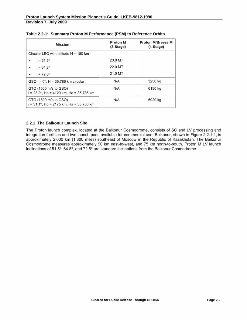
Proton Launch System Mission Planner’s Guide, LKEB-9812-1990 Revision 7, July 2009
Cleared for Public Release Through OFOISR Page 2-2
Table 2.2-1: Summary Proton M Performance (PSM) to Reference Orbits
Mission Proton M (3-Stage)
Proton M/Breeze M (4-Stage)
Circular LEO with altitude H = 180 km
i = 51.5
i = 64.8
i = 72.6
23.0 MT
22.0 MT
21.0 MT
—
GSO i = 0, H = 35,786 km circular N/A 3250 kg
GTO (1500 m/s to GSO) i = 23.2, Hp = 4120 km, Ha = 35,786 km
N/A 6150 kg
GTO (1800 m/s to GSO) i = 31.1, Hp = 2175 km, Ha = 35,786 km
N/A 6920 kg
2.2.1 The Baikonur Launch Site
The Proton launch complex, located at the Baikonur Cosmodrome, consists of SC and LV processing and integration facilities and two launch pads available for commercial use. Baikonur, shown in Figure 2.2.1-1, is approximately 2,000 km (1,300 miles) southeast of Moscow in the Republic of Kazakhstan. The Baikonur Cosmodrome measures approximately 90 km east-to-west, and 75 km north-to-south. Proton M LV launch inclinations of 51.5⁰, 64.8⁰, and 72.6⁰ are standard inclinations from the Baikonur Cosmodrome.

Proton Launch System Mission Planner’s Guide, LKEB-9812-1990 Revision 7, July 2009
Cleared for Public Release Through OFOISR Page 2-3
Figure 2.2.1-1: The Baikonur Launch Site Showing Available Proton M LV Parking Orbit Inclinations

Proton Launch System Mission Planner’s Guide, LKEB-9812-1990 Revision 7, July 2009
Cleared for Public Release Through OFOISR Page 2-4
2.2.2 Launch Availability
The Proton launch system is designed to operate under the environmental conditions encountered at Baikonur (Table 2.2.2-1). The Proton can be launched year round, and the time between launches from an individual pad can be as short as 25 days. Proton has demonstrated a launch rate of four per month from multiple launch pads, and a long-term average launch rate of approximately twelve per year. The capability of the Proton system to launch in severe environmental conditions decreases launch delays and ensures that payloads reach orbit as scheduled to begin revenue-generating activities. The short turnaround time between launches can ensure that SC constellations are deployed quickly, minimizing the time required to enter service.
Table 2.2.2-1: Launch Constraints
Temperature -40C to 45C
Maximum Launch Ground Winds (Standard Commercial PLF)
16.5 m/s
Times Launches available year round
Turn Around Times 25 days per pad
Number of Pads 2 commercial
2.2.3 Breeze M Upper Stage Capabilities
The main engine of the Breeze M can be started up to eight times in flight and allows the stage to offer high precision placement of the SC into orbit. With storable propellant, Breeze M orbital lifetime is limited only by available on-board battery power and is currently 11 hours from LV lift-off to SC separation. The jettisonable Auxiliary Propellant Tank (APT) offers significant mission design flexibility and enables launch services to be offered for low and high energy orbit delivery requirements.

Proton Launch System Mission Planner’s Guide, LKEB-9812-1990 Revision 7, July 2009
Cleared for Public Release Through OFOISR Page 2-5
2.3 PROTON ASCENT PROFILE
2.3.1 Proton Booster Ascent
The Proton LV uses a standard ascent trajectory to place the Orbital Unit (OU), which includes the Breeze M, PLA and SC, into a 170 km to 230 km (92 nmi to 124 nmi) low-earth circular parking orbit inclined at 51.5⁰ after the first Breeze M engine firing. A standard ascent trajectory is required to meet jettisoned stage and payload fairing (PLF) impact point constraints. The use of a standard ascent trajectory also simplifies lower ascent mission design and related analysis, thereby increasing system reliability. Once the OU is in the standard parking orbit the SC can be transferred to its target orbit by the Breeze M.
Table 2.3.1-1 lists the time of occurrence for major ascent events for a typical launch. Figure 2.3.1-1 pictorially illustrates a typical Proton ascent into the standard parking orbit and subsequent Breeze M flight to the target orbit.
At approximately T-1.75 s, the six Stage 1 RD-276 engines are commanded to start at 40% of full thrust. Full thrust is commanded at T-0.15 s. Lift-off confirmation is signaled at T+0.5 s. The staged ignition sequence allows verification that all engines are functioning nominally before being committed to launch. The LV executes a roll maneuver beginning at T+10 s to align the flight azimuth to the desired direction.
Stage 2’s three RD-0210 and one RD-0211 engines are commanded to ignite at 119 s and are commanded to full thrust when Stage 1 is jettisoned at 123 s. Stage 3’s vernier engines are ignited at 332 s followed by Stage 2 shutdown at 334 s.
Stage 2 separation occurs after six small, solid retro-fire motors are ignited at 335 s into flight. Stage 3’s single RD-0213 main engine is ignited at 338 s. PLF jettison typically occurs at 348 s into flight, depending on SC heating constraints. The Stage 3 main engine burns until shutdown at 576 s. The four vernier engines burn for an additional 12 s and are shutdown at 588 s.
The Stage 3 retro-fire motors are ignited and Stage 3 is separated from the Breeze M or SC. Figure 2.3.1-2 shows ascent ground track and jettison points, and ground tracking station acquisition times. Figure 2.3.1-3 shows the times and values for the vehicle’s inertial velocity, altitude, longitudinal acceleration, and dynamic pressure ( ).
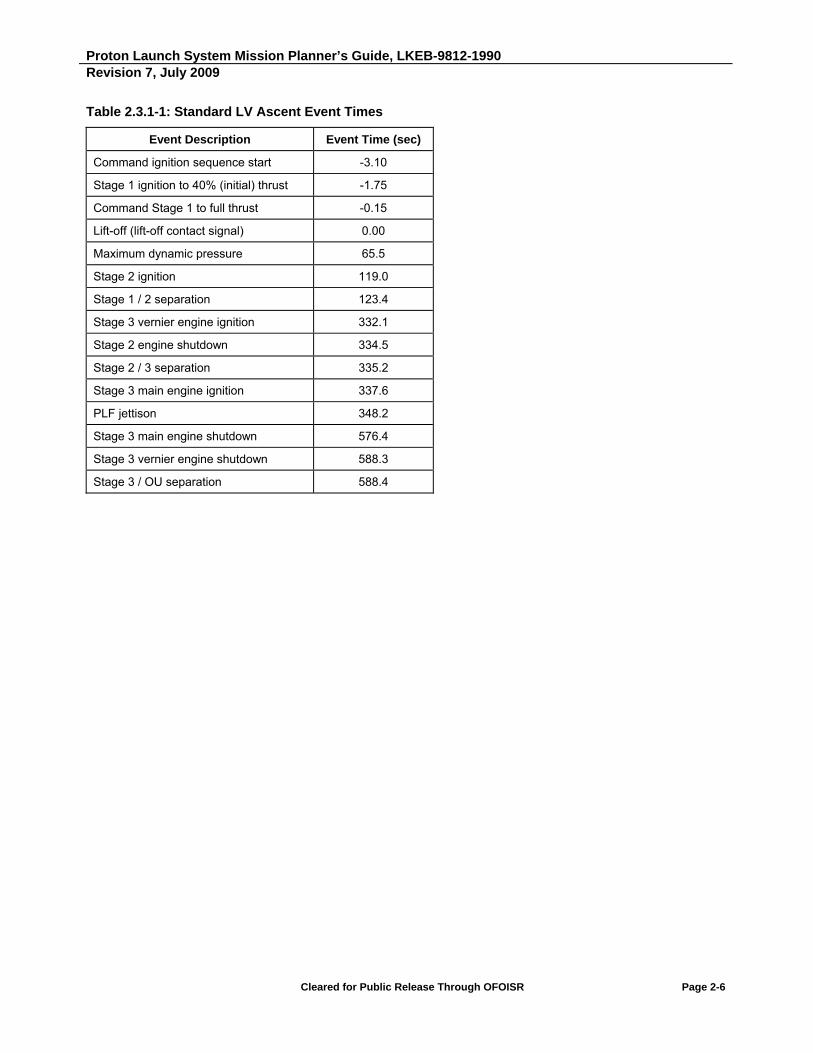
Proton Launch System Mission Planner’s Guide, LKEB-9812-1990 Revision 7, July 2009
Cleared for Public Release Through OFOISR Page 2-6
Table 2.3.1-1: Standard LV Ascent Event Times
Event Description Event Time (sec)
Command ignition sequence start -3.10
Stage 1 ignition to 40% (initial) thrust -1.75
Command Stage 1 to full thrust -0.15
Lift-off (lift-off contact signal) 0.00
Maximum dynamic pressure 65.5
Stage 2 ignition 119.0
Stage 1 / 2 separation 123.4
Stage 3 vernier engine ignition 332.1
Stage 2 engine shutdown 334.5
Stage 2 / 3 separation 335.2
Stage 3 main engine ignition 337.6
PLF jettison 348.2
Stage 3 main engine shutdown 576.4
Stage 3 vernier engine shutdown 588.3
Stage 3 / OU separation 588.4

Proton Launch System Mission Planner’s Guide, LKEB-9812-1990 Revision 7, July 2009
Cleared for Public Release Through OFOISR Page 2-7
Figure 2.3.1-1: Typical Proton M LV Ascent Plus Breeze M Main Engine Burns
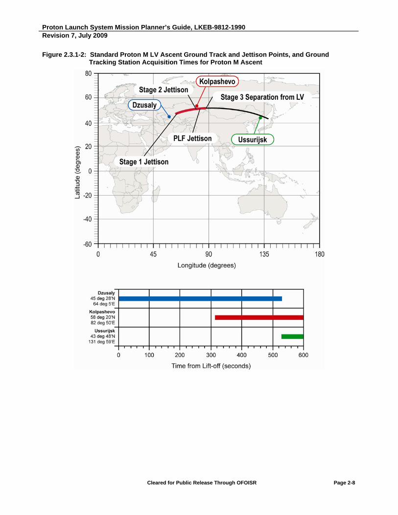
Proton Launch System Mission Planner’s Guide, LKEB-9812-1990 Revision 7, July 2009
Cleared for Public Release Through OFOISR Page 2-8
Figure 2.3.1-2: Standard Proton M LV Ascent Ground Track and Jettison Points, and Ground Tracking Station Acquisition Times for Proton M Ascent

Proton Launch System Mission Planner’s Guide, LKEB-9812-1990 Revision 7, July 2009
Cleared for Public Release Through OFOISR Page 2-9
Figure 2.3.1-3: Typical Proton M Lower Ascent Altitude, Inertial Velocity, Longitudinal Acceleration, and Dynamic Pressure

Proton Launch System Mission Planner’s Guide, LKEB-9812-1990 Revision 7, July 2009
Cleared for Public Release Through OFOISR Page 2-10
2.3.2 Breeze M Standard Mission Profile
The first three stages of the Proton LV inject the Breeze M/SC into a sub-orbital trajectory. After the Proton third stage separation, Breeze M performs the first of five main engine burns that inject the Breeze M/SC into a standard low earth parking orbit. After coasting in the parking orbit for about 50 minutes, the second burn takes place near the first ascending node. This second burn serves as an initial phase of the process of raising the transfer orbit apogee to the geosynchronous apogee altitude. This burn transfers Breeze M into an intermediate transfer orbit with an apogee of 5000 to 7000 km. The actual apogee altitude is determined by the optimized mission design and the final SC mass. After coasting for one revolution in the intermediate orbit, about 2 to 2.5 hours after the second burn, the third and the fourth burns take place across the second ascending node. The duration of the third burn is defined by the complete depletion of the propellant in the APT. When the propellant in this tank is depleted, the main engine shuts down for two minutes while the APT is jettisoned. The fourth burn occurs after APT separation. This fourth burn raises the apogee of the transfer orbit to the altitude of a Geosynchronous Orbit (GEO). The perigee altitude, as well as the transfer orbit inclination, can be modified somewhat in the course of the mission optimization that takes place during the mission integration phase.
During Breeze M coast along the parking, intermediate and transfer orbits, the SC attitude can be changed to meet thermal environment and Sun exposure requirements. To ensure that the SC surface is evenly heated (or cooled), Breeze M can be preprogrammed either to periodically roll 180 degrees about the Breeze M longitudinal Х-axis or pitch about its transverse Z-axis, or to roll continuously about the Breeze M longitudinal X-axis with an angular rate of up to 3 deg/s.
After approximately 5.2 hours in the transfer orbit, the Breeze M performs a fifth burn, which raises perigee and lowers inclination into a Geosynchronous Transfer Orbit (GTO) with the desired target orbit parameters. When this burn is completed, the Breeze M performs a maneuver to orient the SC for separation, which takes place within 12 - 40 minutes of the end of the final burn. The total time of the Breeze M standard mission profile from LV lift-off to SC separation is approximately 9.3 hours.
In the standard “9-hour” Breeze M mission profile described above, the SC is injected into the target orbit from the ascending node of the parking orbit, and SC separation occurs at 52 degrees East longitude. If, however, the Customer requires a longitude at separation other than 52 degrees East, then Breeze M can either remain in the parking orbit or in the intermediate orbit for a longer period of time. Each additional revolution in the parking orbit will change the separation point longitude by 22.5 degrees to the west. Similarly, each additional revolution in the intermediate orbit (with 5,000 km apogee) will move the separation point longitude by approximately 35 degrees to the west. Other values of separation longitude can be achieved by choosing different intermediate orbit apogees. In general, the number of revolutions that the Breeze M remains in the parking orbit or the intermediate orbit will be determined in the course of the mission design optimization process during the mission integration phase.
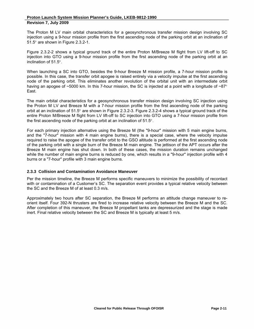
Proton Launch System Mission Planner’s Guide, LKEB-9812-1990 Revision 7, July 2009
Cleared for Public Release Through OFOISR Page 2-11
The Proton M LV main orbital characteristics for a geosynchronous transfer mission design involving SC injection using a 9-hour mission profile from the first ascending node of the parking orbit at an inclination of 51.5 are shown in Figure 2.3.2-1.
Figure 2.3.2-2 shows a typical ground track of the entire Proton M/Breeze M flight from LV lift-off to SC injection into GTO using a 9-hour mission profile from the first ascending node of the parking orbit at an inclination of 51.5.
When launching a SC into GTO, besides the 9-hour Breeze M mission profile, a 7-hour mission profile is possible. In this case, the transfer orbit apogee is raised entirely via a velocity impulse at the first ascending node of the parking orbit. This eliminates another revolution of the orbital unit with an intermediate orbit having an apogee of ~5000 km. In this 7-hour mission, the SC is injected at a point with a longitude of ~87 East.
The main orbital characteristics for a geosynchronous transfer mission design involving SC injection using the Proton M LV and Breeze M with a 7-hour mission profile from the first ascending node of the parking orbit at an inclination of 51.5 are shown in Figure 2.3.2-3. Figure 2.3.2-4 shows a typical ground track of the entire Proton M/Breeze M flight from LV lift-off to SC injection into GTO using a 7-hour mission profile from the first ascending node of the parking orbit at an inclination of 51.5.
For each primary injection alternative using the Breeze M (the "9-hour" mission with 5 main engine burns, and the "7-hour" mission with 4 main engine burns), there is a special case, where the velocity impulse required to raise the apogee of the transfer orbit to the GSO altitude is performed at the first ascending node of the parking orbit with a single burn of the Breeze M main engine. The jettison of the APT occurs after the Breeze M main engine has shut down. In both of these cases, the mission duration remains unchanged while the number of main engine burns is reduced by one, which results in a "9-hour" injection profile with 4 burns or a "7-hour" profile with 3 main engine burns.
2.3.3 Collision and Contamination Avoidance Maneuver
Per the mission timeline, the Breeze M performs specific maneuvers to minimize the possibility of recontact with or contamination of a Customer’s SC. The separation event provides a typical relative velocity between the SC and the Breeze M of at least 0.3 m/s.
Approximately two hours after SC separation, the Breeze M performs an attitude change maneuver to re-orient itself. Four 392-N thrusters are fired to increase relative velocity between the Breeze M and the SC. After completion of this maneuver, the Breeze M propellant tanks are depressurized and the stage is made inert. Final relative velocity between the SC and Breeze M is typically at least 5 m/s.

Proton Launch System Mission Planner’s Guide, LKEB-9812-1990 Revision 7, July 2009
Cleared for Public Release Through OFOISR Page 2-12
2.4 PERFORMANCE GROUND RULES
A number of standard mission ground rules have been used to develop the reference Proton M/Breeze M performance capabilities identified in this document. They are described in this section.
2.4.1 Payload Systems Mass Definition
Performance capabilities quoted throughout this document are presented in terms of Payload Systems Mass (PSM). PSM is defined as the total mission unique mass delivered to the target orbit, including the separated SC, the SC-to-LV adapter, and all other mission-specific hardware required on the LV to support the payload (e.g., harnessing, purge hardware etc.). Table 4.1.4-1 provides masses for the available Proton M adapter systems.
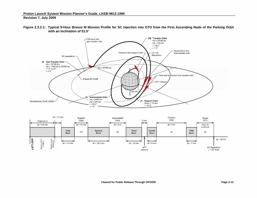
Proton Launch System Mission Planner’s Guide, LKEB-9812-1990 Revision 7, July 2009
Cleared for Public Release Through OFOISR Page 2-13
Figure 2.3.2-1: Typical 9-Hour Breeze M Mission Profile for SC Injection into GTO from the First Ascending Node of the Parking Orbit with an Inclination of 51.5

Proton Launch System Mission Planner’s Guide, LKEB-9812-1990 Revision 7, July 2009
Cleared for Public Release Through OFOISR Page 2-14
Figure 2.3.2-2: Typical Ground Track of the Proton M Breeze M Flight for SC Injection into GTO Using a 9-Hour Mission Profile from the First Ascending Node of the Parking Orbit with an Inclination of 51.5
1 - LV insertion phase 2 - Breeze M main engine first firing - parking orbit insertion 3 - Breeze M main engine second firing - intermediate orbit insertion 4, 5 - Breeze M main engine third and fourth firings - transfer orbit insertion 6 - Breeze M main engine fifth firing - geo-transfer orbit insertion

Proton Launch System Mission Planner’s Guide, LKEB-9812-1990 Revision 7, July 2009
Cleared for Public Release Through OFOISR Page 2-15
Figure 2.3.2-3: Typical 7-Hour Breeze M Mission Profile for SC Injection into GTO from the First Ascending Node of the Parking Orbit with an Inclination of 51.5

Proton Launch System Mission Planner’s Guide, LKEB-9812-1990 Revision 7, July 2009
Cleared for Public Release Through OFOISR Page 2-16
Figure 2.3.2-4: Typical Ground Track of the Proton M Breeze M Flight for SC Injection into GTO Using a 7-Hour Mission Profile from the First Ascending Node of the Parking Orbit with an Inclination of 51.5

Proton Launch System Mission Planner’s Guide, LKEB-9812-1990 Revision 7, July 2009
Cleared for Public Release Through OFOISR Page 2-17
2.4.2 Payload Fairings
Currently, two PLFs are offered for Proton M Breeze M missions. These PLFs are described in Section 4. All performance tables for GTO missions described in this section assume the use of the 15255 mm long PLF (PLF-BR-15255). For GTO missions using the lighter 13305 mm long PLF (PLF-BR-13305) design, a performance increase of 15 kg to GTO can be assumed.
PLF jettison times are constrained to occur so that fairing hardware will impact in designated areas. For Proton M/Breeze M flights, fairing jettison occurs at approximately 340 to 350 seconds into the flight at an altitude of 121 to 125 kilometers or more. Maximum Free Molecular Heat Flux (FMHF) after PLF jettison does not exceed 1135 W/m2.
2.4.3 Mission Analysis Ground Rules
All Proton M mission estimates provided in this document assume launch from the Baikonur Cosmodrome. Launch Pads 24 and 39 at Baikonur are located at 46.1 degrees North geodetic latitude and 63.0 degrees East longitude. All identified altitudes are based on a spherical Earth radius of 6378 km for GTO missions.
Caution must be exercised in deriving performance estimates for missions whose inclinations differ from those presented. The first three stages of the Proton M launch system can only deliver payloads directly into, or near, the standard low earth orbit at an inclination of 51.5, 64.8, or 72.6 degrees. All other inclinations can be reached only through an orbital plane change maneuver. Performance estimates should not be made based on interpolation between performance values derived from different parking orbit inclinations.
2.4.4 Performance Confidence Levels
Proton M missions are targeted to meet the requirements of each user. Most Proton M missions are targeted based on a conservative 2.33 confidence level that the mission objectives will be achieved. All Proton M/Breeze M performance information contained in this document assumes adequate propellant margin to meet a 2.33 confidence level. Proton M LEO performance assumes a 3 propellant margin.
For Customers desiring information about 3 propellant margins for standard GTO Proton M missions, it can be assumed that standard 9-hour (five-burn) Breeze M mission performance is reduced by 40 kg from the values in Table 2.5.2-2, and 7-hour (four-burn) Breeze M mission performance is reduced by 45 kg from the values in Table 2.5.2-1.

Proton Launch System Mission Planner’s Guide, LKEB-9812-1990 Revision 7, July 2009
Cleared for Public Release Through OFOISR Page 2-18
2.5 GEOSYNCHRONOUS TRANSFER MISSIONS
2.5.1 Launch to GTO/GSO
The elliptical GTO transfer mission is the standard mission profile for most commercial Proton launches. Variable mass SC are delivered to a GTO with a 35,786 km apogee altitude, a 0° argument of perigee, and a variable orbit perigee and inclination consistent with the lift-off mass of the SC and the delivered LV performance. From this point, the SC will perform the remaining perigee raising and inclination reduction to reach GSO.
For the purpose of establishing a baseline, ILS uses a reference geosynchronous transfer mission performance quotation based on an injection orbit where the SC -velocity to GSO equals 1,500 m/s. This reference mission is indicative of the geosynchronous transfer missions used by vehicles launched from low inclination launch sites. The reference orbit assumes a 4,120 km perigee altitude, a 35,786 km apogee altitude, a 23.2° orbit inclination, and a 0° argument of perigee.
A SC with a PSM of 3250 kg or less can be injected by the Breeze M directly into GSO. This is made possible by the mission design flexibility and orbital lifetime capability of the Breeze M, and can offer substantial advantages to the SC manufacturer and operator through the elimination of the mass, complexity and cost of the SC apogee propulsion system.
2.5.2 Proton M Breeze M Performance
The Proton M/Breeze M performance to GTO with a GSO apogee is shown in Figures 2.5.2-1 and 2.5.2-2. Data is shown that represents LV performance in terms of PSM versus residual SC -velocity from GTO to GSO. Analyses have been conducted to determine the optimum orbit that can be achieved with Proton M for a given PSM. Given a payload mass and launch from the Baikonur Cosmodrome, the Breeze M delivers the SC to a GTO that results in minimum spacecraft -velocity remaining to reach GSO.
Two major variations of the Breeze M injection to GTO/GSO, described in Section 2.3.2, have been demonstrated with successful missions. As of 31 July 2009, the 9-hour mission has been flown 19 times to GTO using 5 burns of the main engine and five times to GSO using 4 burns. The 7-hour mission has been flown successfully two times to GTO (one 4-burn and one 3-burn) and one time to GSO (3-burn).
As shown in Tables 2.5.2-1 and 2.5.2-2, performance to GTO for the 7-hour mission is considerably lower than for the 9-hour mission due to increased gravity losses (increased propellant consumption) during burns at the first ascending node to raise the apogee of the transfer orbit.
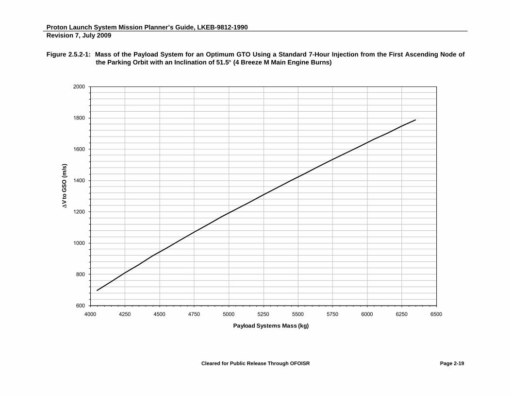
Proton Launch System Mission Planner’s Guide, LKEB-9812-1990 Revision 7, July 2009
Cleared for Public Release Through OFOISR Page 2-19
Figure 2.5.2-1: Mass of the Payload System for an Optimum GTO Using a Standard 7-Hour Injection from the First Ascending Node of the Parking Orbit with an Inclination of 51.5 (4 Breeze M Main Engine Burns)
600
800
1000
1200
1400
1600
1800
2000
4000 4250 4500 4750 5000 5250 5500 5750 6000 6250 6500
V
to G
SO
(m
/s)
Payload Systems Mass (kg)

Proton Launch System Mission Planner’s Guide, LKEB-9812-1990 Revision 7, July 2009
Cleared for Public Release Through OFOISR Page 2-20
Figure 2.5.2-2: Mass of the Payload System for an Optimum GTO Using Standard 9-Hour Injection from the First Ascending Node of the Parking Orbit with an Inclination of 51.5 (5 Breeze M Main Engine Burns)
600
800
1000
1200
1400
1600
1800
2000
4000 4500 5000 5500 6000 6500 7000 7500
V
to G
SO
(m
/s)
Payload Systems Mass (kg)

Proton Launch System Mission Planner’s Guide, LKEB-9812-1990 Revision 7, July 2009
Cleared for Public Release Through OFOISR Page 2-21
The derived orbit parameters are provided in Table 2.5.2-1 for a 7-hour/4-burn Breeze M mission, and Table 2.5.2-2 for a 9-hour/5-burn Breeze M mission. Parametric performance to non-optimized GTOs using the 9-hour/five-burn Breeze M mission design is provided in Table 2.5.2-3.
Argument of Perigee can be varied as a design parameter of the GTO target orbit. Baseline Proton performance in Tables 2.5.2-1 through 2.5.2-3 assumes an argument of perigee of 0 degree. Argument of perigee can be adjusted to 5 degrees at a performance penalty of 10 kg, and adjusted to 10 degrees at a performance penalty of 27 kg.
The Breeze M’s capability for up to eight main engine restarts and up to an 11-hour mission duration allow great flexibility for customized mission designs. Customers with unique mission requirements are encouraged to contact ILS to obtain more information about how the Breeze M can meet their specific needs.

Proton Launch System Mission Planner’s Guide, LKEB-9812-1990 Revision 7, July 2009
Cleared for Public Release Through OFOISR Page 2-22
Table 2.5.2-1: Proton M/Breeze M Performance for an Optimum GTO Using a Standard 7-Hour Injection from the First Ascending Node of the Parking Orbit with an Inclination of 51.5 (4 Breeze M Main Engine Burns)
PSM (kg)
GTO Parameters Minimum SC Velocity for Transfer to GSO,
Vsc (m/s) Inclination
(deg)
Perigee Altitude
(km)
Apogee Altitude
(km)
Argument of Perigee (deg)
4050 8.20 14480 35,786 0 697
4150 9.00 13410 35,786 0 753
4250 9.80 12412 35,786 0 808
4350 10.70 11557 35,786 0 862
4450 11.60 10728 35,786 0 916
4550 12.40 9931 35,786 0 967
4650 13.30 9230 35,786 0 1018
4750 14.20 8571 35,786 0 1068
4850 15.20 7996 35,786 0 1118
4950 16.10 7414 35,786 0 1166
5050 17.10 6910 35,786 0 1214
5150 18.00 6395 35,786 0 1260
5250 18.90 5887 35,786 0 1306
5350 19.90 5449 35,786 0 1352
5450 20.87 4997 35,786 0 1398
5550 21.90 4609 35,786 0 1443
5650 22.90 4228 35,786 0 1487
5750 24.00 3908 35,786 0 1531
5850 25.10 3614 35,786 0 1574
5950 26.20 3318 35,786 0 1617
6050 27.30 3021 35,786 0 1660
6150 28.40 2744 35,786 0 1702
6250 29.54 2489 35,786 0 1744
6350 30.70 2271 35,786 0 1785
SC separation occurs at a geographic longitude of 87 E. Performance is based on the use of a standard PLF-BR-15255. FMHF at fairing jettison shall not exceed 1135 W/m2. The PSM includes LV adapter system mass. The PSM is calculated based on a 2.33 confidence level Breeze M propellant margin.

Proton Launch System Mission Planner’s Guide, LKEB-9812-1990 Revision 7, July 2009
Cleared for Public Release Through OFOISR Page 2-23
Table 2.5.2-2: Proton M/Breeze M Performance for an Optimum GTO Using a Standard 9-Hour Injection from the First Ascending Node of the Parking Orbit with an Inclination of 51.5 (5 Breeze M Main Engine Burns)
PSM (kg)
GTO Parameters Minimum SC Velocity for
Transfer to GSO, Vsc (m/s)
Inclination (deg)
Perigee Altitude
(km)
Apogee Altitude
(km)
Argument of Perigee (deg)
4450 8.60 13,814 35,786 0 729
4550 9.30 13,020 35,786 0 774
4650 10.10 12,211 35,786 0 823
4750 10.90 11,400 35,786 0 873
4850 11.70 10,610 35,786 0 923
4950 12.50 9898 35,786 0 971
5050 13.30 9204 35,786 0 1019
5150 14.20 8597 35,786 0 1067
5250 15.10 8028 35,786 0 1114
5350 16.00 7495 35,786 0 1160
5450 16.90 6995 35,786 0 1205
5550 17.80 6527 35,786 0 1249
5650 18.60 6025 35,786 0 1292
5750 19.50 5591 35,786 0 1335
5850 20.40 5186 35,786 0 1377
5950 21.30 4807 35,786 0 1418
6050 22.20 4432 35,786 0 1459
6150 23.20 4120 35,786 0 1500
6250 24.20 3830 35,786 0 1540
6350 25.20 3540 35,786 0 1580
6450 26.20 3250 35,786 0 1620
6550 27.20 2981 35,786 0 1659
6650 28.25 2742 35,786 0 1698
6750 29.30 2529 35,786 0 1736
6850 30.35 2329 35,786 0 1773
6950 31.40 2135 35,786 0 1810
7050 32.50 1970 35,786 0 1847
7150 33.60 1816 35,786 0 1883
SC separation occurs at a geographic longitude of 52 E. Performance is based on the use of a standard PLF-BR-15255. FMHF at fairing jettison shall not exceed 1135 W/m2. The PSM includes LV adapter system mass. The PSM is calculated based on a 2.33 confidence level Breeze M propellant margin.

Proton Launch System Mission Planner’s Guide, LKEB-9812-1990 Revision 7, July 2009
Cleared for Public Release Through OFOISR Page 2-24
Table 2.5.2-3: Proton M/Breeze M Parametric Performance for a Non-Optimum GTO Using a Standard 9-Hour Injection from the First Ascending Node of the Parking Orbit with an Inclination of 51.5 (5 Breeze M Main Engine Burns)
PSM (kg)
GTO Parameters SC Velocity for
Transfer to GSO, VSC (m/s)
Inclination (deg)
Perigee Altitude
(km)
Apogee Altitude
(km)
Argument of Perigee
(deg)
4450
8.0 13,283 35,786 0 731
7.1 12,508 35,786 0 738
6.1 11,680 35,786 0 751
4550
8.6 12,429 35,786 0 776
7.6 11,600 35,786 0 784
6.6 10,786 35,786 0 798
4650
9.4 11,632 35,786 0 825
8.3 10,736 35,786 0 834
7.2 9882 35,786 0 849
4750
10.2 10,834 35,786 0 875
9.6 10,355 35,786 0 879
9.0 9906 35,786 0 884
8.5 9505 35,786 0 891
7.8 8975 35,786 0 902
4850
11.0 10,062 35,786 0 925
10.4 9595 35,786 0 929
9.8 9134 35,786 0 935
9.2 8698 35,786 0 942
8.5 8173 35,786 0 954
4950
11.8 9364 35,786 0 973
11.1 8829 35,786 0 978
10.5 8385 35,786 0 984
9.9 7943 35,786 0 992
9.1 7375 35,786 0 1005
5050
12.6 8685 35,786 0 1021
11.9 8163 35,786 0 1026
11.2 7662 35,786 0 1033
10.6 7217 35,786 0 1042
9.8 6650 35,786 0 1056

Proton Launch System Mission Planner’s Guide, LKEB-9812-1990 Revision 7, July 2009
Cleared for Public Release Through OFOISR Page 2-25
PSM (kg)
GTO Parameters SC Velocity for
Transfer to GSO, VSC (m/s)
Inclination (deg)
Perigee Altitude
(km)
Apogee Altitude
(km)
Argument of Perigee
(deg)
5150
13.5 8085 35,786 0 1069
12.7 7496 35,786 0 1075
12.0 7008 35,786 0 1082
11.4 6575 35,786 0 1091
10.5 5936 35,786 0 1108
5250
14.4 7523 35,786 0 1116
13.6 6963 35,786 0 1121
12.8 6395 35,786 0 1130
12.1 5898 35,786 0 1141
11.2 5267 35,786 0 1159
5350
15.3 6997 35,786 0 1162
14.4 6371 35,786 0 1168
13.6 5819 35,786 0 1177
12.9 5317 35,786 0 1189
11.9 4640 35,786 0 1209
5450
16.1 6445 35,786 0 1207
15.2 5815 35,786 0 1214
14.4 5260 35,786 0 1224
13.7 4771 35,786 0 1236
12.7 4080 35,786 0 1258
5550
17.1 6041 35,786 0 1251
16.1 5360 35,786 0 1258
15.2 4733 35,786 0 1270
14.5 4258 35,786 0 1282
13.5 3555 35,786 0 1306
5650
17.9 5550 35,786 0 1294
16.9 4866 35,786 0 1302
16.0 4238 35,786 0 1315
15.3 3742 35,786 0 1329
14.3 3060 35,786 0 1353
5750
18.9 5180 35,786 0 1337
17.8 4429 35,786 0 1346
16.9 3810 35,786 0 1359
16.2 3323 35,786 0 1373
15.2 2607 35,786 0 1400
Proton Launch System Mission Planner’s Guide, LKEB-9812-1990 Revision 7, July 2009
Cleared for Public Release Through OFOISR Page 2-26
PSM (kg)
GTO Parameters SC Velocity for
Transfer to GSO, VSC (m/s)
Inclination (deg)
Perigee Altitude
(km)
Apogee Altitude
(km)
Argument of Perigee
(deg)
5850
19.8 4780 35,786 0 1379
18.7 4018 35,786 0 1389
17.8 3391 35,786 0 1403
17.1 2896 35,786 0 1418
16.1 2167 35,786 0 1447
5950
20.7 4404 35,786 0 1420
19.6 3631 35,786 0 1431
18.8 3068 35,786 0 1444
18.1 2574 35,786 0 1459
17.0 1738 35,786 0 1494
6050
21.7 4089 35,786 0 1461
20.6 3314 35,786 0 1472
19.8 2750 35,786 0 1485
19.0 2164 35,786 0 1504
18.0 1360 35,786 0 1540
SC separation occurs at a geographic longitude of 52 E. Performance is based on the use of a standard PLF-BR-15255. FMHF at fairing jettison shall not exceed 1135 W/m2. The PSM includes LV adapter system mass. The PSM is calculated based on a 2.33 confidence level Breeze M propellant margin.
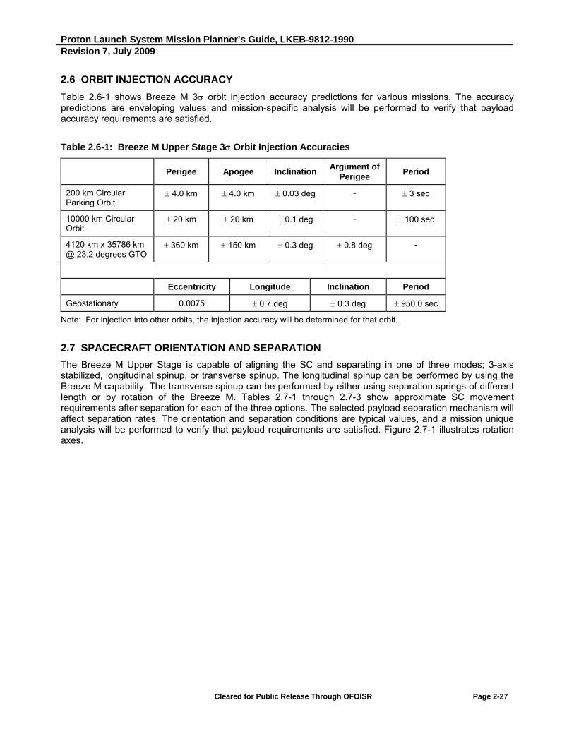
Proton Launch System Mission Planner’s Guide, LKEB-9812-1990 Revision 7, July 2009
Cleared for Public Release Through OFOISR Page 2-27
2.6 ORBIT INJECTION ACCURACY
Table 2.6-1 shows Breeze M 3 orbit injection accuracy predictions for various missions. The accuracy predictions are enveloping values and mission-specific analysis will be performed to verify that payload accuracy requirements are satisfied.
Table 2.6-1: Breeze M Upper Stage 3 Orbit Injection Accuracies
Perigee Apogee Inclination Argument of
Perigee Period
200 km Circular Parking Orbit
4.0 km 4.0 km 0.03 deg - 3 sec
10000 km Circular Orbit
20 km 20 km 0.1 deg - 100 sec
4120 km x 35786 km @ 23.2 degrees GTO
360 km 150 km 0.3 deg 0.8 deg -
Eccentricity Longitude Inclination Period
Geostationary 0.0075 0.7 deg 0.3 deg 950.0 sec
Note: For injection into other orbits, the injection accuracy will be determined for that orbit.
2.7 SPACECRAFT ORIENTATION AND SEPARATION
The Breeze M Upper Stage is capable of aligning the SC and separating in one of three modes; 3-axis stabilized, longitudinal spinup, or transverse spinup. The longitudinal spinup can be performed by using the Breeze M capability. The transverse spinup can be performed by either using separation springs of different length or by rotation of the Breeze M. Tables 2.7-1 through 2.7-3 show approximate SC movement requirements after separation for each of the three options. The selected payload separation mechanism will affect separation rates. The orientation and separation conditions are typical values, and a mission unique analysis will be performed to verify that payload requirements are satisfied. Figure 2.7-1 illustrates rotation axes.

Proton Launch System Mission Planner’s Guide, LKEB-9812-1990 Revision 7, July 2009
Cleared for Public Release Through OFOISR Page 2-28
Table 2.7-1: SC Separation Accuracies, Longitudinal Spin
Reference Value
SC spin rate about spin axis 6 deg/s 1 deg/s
SC tip-off rate about perpendicular spin axes 1.1 deg/s
Relative separation velocity 0.35 m/s
Error of spin axis orientation 5 deg
Table 2.7-2: SC Separation Accuracies, Transverse Spin
Reference Value
SC spin rate about spin axis 2 deg/s 1 deg/s
SC tip-off rate about perpendicular spin axes 0.7 deg/s
Relative separation velocity 0.5 m/s
Error of spin axis orientation 5 deg
Table 2.7-3: SC Separation Accuracies, Three-Axis Stabilized
Reference Value
Relative separation velocity 0.3 m/s
SC tip-off rate about any of SC axes 1.0 deg/s
SC separation attitude error 5 deg
Figure 2.7-1: Separation Axes Definition

Proton Launch System Mission Planner’s Guide, LKEB-9812-1990 Revision 7, July 2009
Cleared for Public Release Through OFOISR Page 2-29
2.8 LAUNCH VEHICLE TELEMETRY DATA
ILS has adopted standard formats regarding orbital state vector data that are provided to the launch services Customer during and after the launch mission. These standard formats enable the satellite operator to properly determine orbital conditions at various times during the mission. The standard data is transmitted to the SC Mission Control Center at relevant times.
The data formats are:
Format I - Preliminary injection orbit parameters (Table 2.8-1) 30 minutes after SC separation
Format II - Breeze M attitude parameters prior to SC separation (Table 2.8-2) 60 minutes after SC separation
Format III - Final target orbit data (Table 2.8-3) no later than 180 minutes after SC separation
ILS will provide in Formats I - III, Tables 2.8-1 through 2.8-3, respectively, US state vector data at SC separation and Breeze M attitude data prior to SC separation. Format I is normally provided only for the target orbit, but may be provided for the transfer orbit on Customer request. Submittal times for the additional Format I data will be established during the mission integration phase.
The formatted telemetered data is submitted to the Customer by ILS at Baikonur via fax or voice to the SC Mission Control Center.
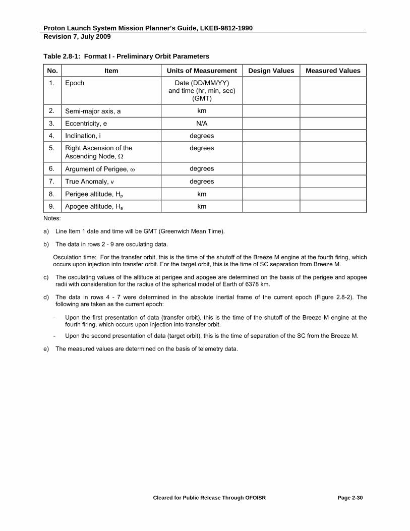
Proton Launch System Mission Planner’s Guide, LKEB-9812-1990 Revision 7, July 2009
Cleared for Public Release Through OFOISR Page 2-30
Table 2.8-1: Format I - Preliminary Orbit Parameters
No. Item Units of Measurement Design Values Measured Values
1. Epoch Date (DD/MM/YY) and time (hr, min, sec)
(GMT)
2. Semi-major axis, a km
3. Eccentricity, e N/A
4. Inclination, i degrees
5. Right Ascension of the Ascending Node,
degrees
6. Argument of Perigee, degrees
7. True Anomaly, ν degrees
8. Perigee altitude, Hp km
9. Apogee altitude, Ha km
Notes:
a) Line Item 1 date and time will be GMT (Greenwich Mean Time).
b) The data in rows 2 - 9 are osculating data.
Osculation time: For the transfer orbit, this is the time of the shutoff of the Breeze M engine at the fourth firing, which occurs upon injection into transfer orbit. For the target orbit, this is the time of SC separation from Breeze M.
c) The osculating values of the altitude at perigee and apogee are determined on the basis of the perigee and apogee radii with consideration for the radius of the spherical model of Earth of 6378 km.
d) The data in rows 4 - 7 were determined in the absolute inertial frame of the current epoch (Figure 2.8-2). The following are taken as the current epoch:
- Upon the first presentation of data (transfer orbit), this is the time of the shutoff of the Breeze M engine at the fourth firing, which occurs upon injection into transfer orbit.
- Upon the second presentation of data (target orbit), this is the time of separation of the SC from the Breeze M.
e) The measured values are determined on the basis of telemetry data.
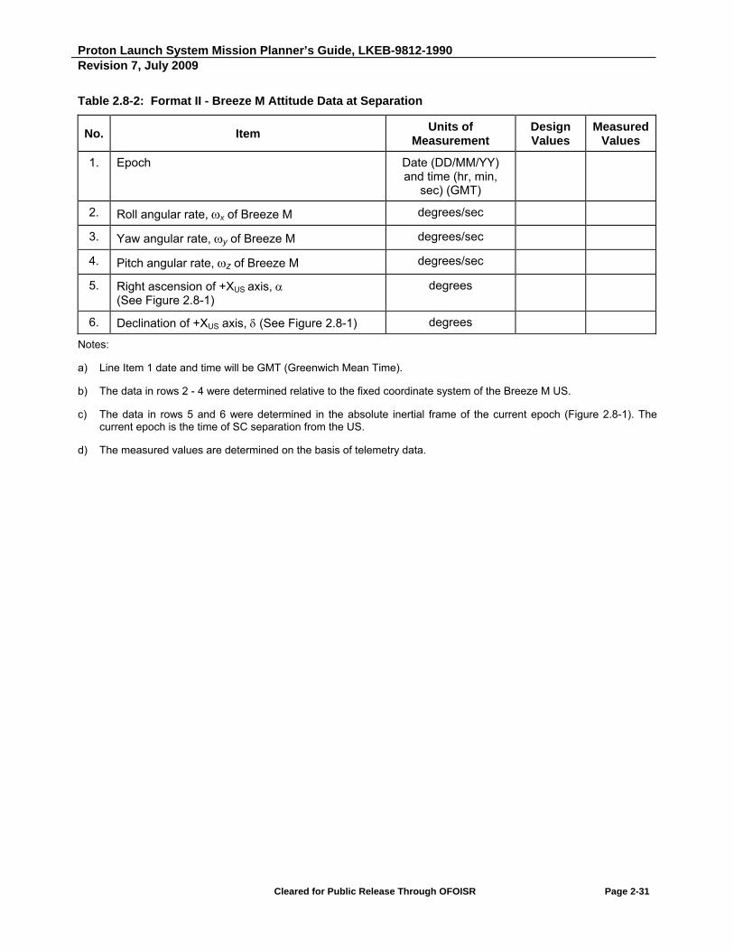
Proton Launch System Mission Planner’s Guide, LKEB-9812-1990 Revision 7, July 2009
Cleared for Public Release Through OFOISR Page 2-31
Table 2.8-2: Format II - Breeze M Attitude Data at Separation
No. Item Units of
Measurement Design Values
Measured Values
1. Epoch Date (DD/MM/YY) and time (hr, min,
sec) (GMT)
2. Roll angular rate, x of Breeze M degrees/sec
3. Yaw angular rate, y of Breeze M degrees/sec
4. Pitch angular rate, z of Breeze M degrees/sec
5. Right ascension of +XUS axis, (See Figure 2.8-1)
degrees
6. Declination of +XUS axis, (See Figure 2.8-1) degrees
Notes:
a) Line Item 1 date and time will be GMT (Greenwich Mean Time).
b) The data in rows 2 - 4 were determined relative to the fixed coordinate system of the Breeze M US.
c) The data in rows 5 and 6 were determined in the absolute inertial frame of the current epoch (Figure 2.8-1). The current epoch is the time of SC separation from the US.
d) The measured values are determined on the basis of telemetry data.

Proton Launch System Mission Planner’s Guide, LKEB-9812-1990 Revision 7, July 2009
Cleared for Public Release Through OFOISR Page 2-32
Table 2.8-3: Format III - Final SC Target Orbit Data
No. Item Units of Measurement Design Values
Measured Values
1. Lift-off time Date (DD/MM/YY) and time (hr, min, sec) (GMT)
2. Epoch Date (DD/MM/YY) and time (hr, min, sec) (GMT)
3. Semi-major axis, a km
4. Eccentricity, e N/A
5. Inclination, i degrees
6. Right Ascension of the Ascending Node,
degrees
7. Argument of Perigee, degrees
8. True Anomaly, ν degrees
9. Perigee altitude, Hp km
10. Apogee altitude, Ha km
11. Separation longitude degrees
12. Separation latitude degrees
Notes:
a) The date and time in Line Items 1 and 2 will be GMT (Greenwich Mean Time).
b) Osculating data will be provided in Line Items 3 - 10. The osculating time is the time of separation of the SC and Breeze M Upper Stage.
c) The osculating values of the altitude at perigee and apogee are determined on the basis of the perigee and apogee radius with consideration for the radius of the spherical model of Earth of 6378 km.
d) Data in rows 5 - 8 are defined in absolute inertial coordinate system of a current epoch (Figure 2.8-2). The current epoch is the time of SC separation from the US.
e) The measured values are determined on the basis of telemetry data.
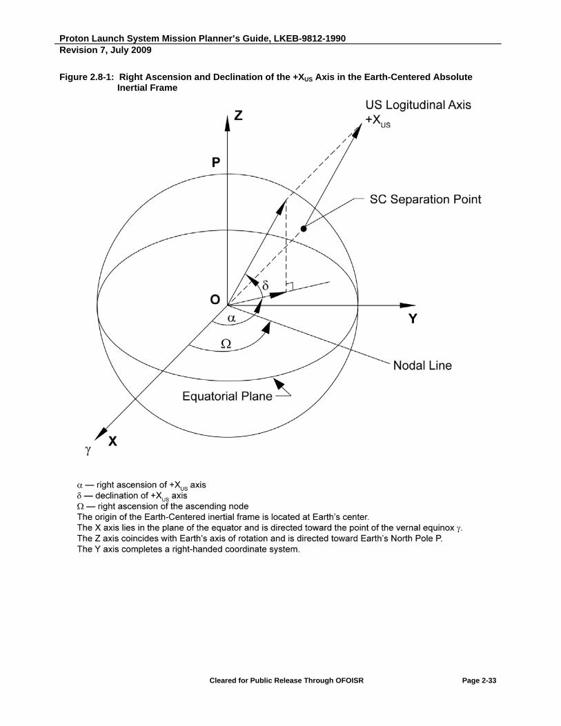
Proton Launch System Mission Planner’s Guide, LKEB-9812-1990 Revision 7, July 2009
Cleared for Public Release Through OFOISR Page 2-33
Figure 2.8-1: Right Ascension and Declination of the +XUS Axis in the Earth-Centered Absolute Inertial Frame
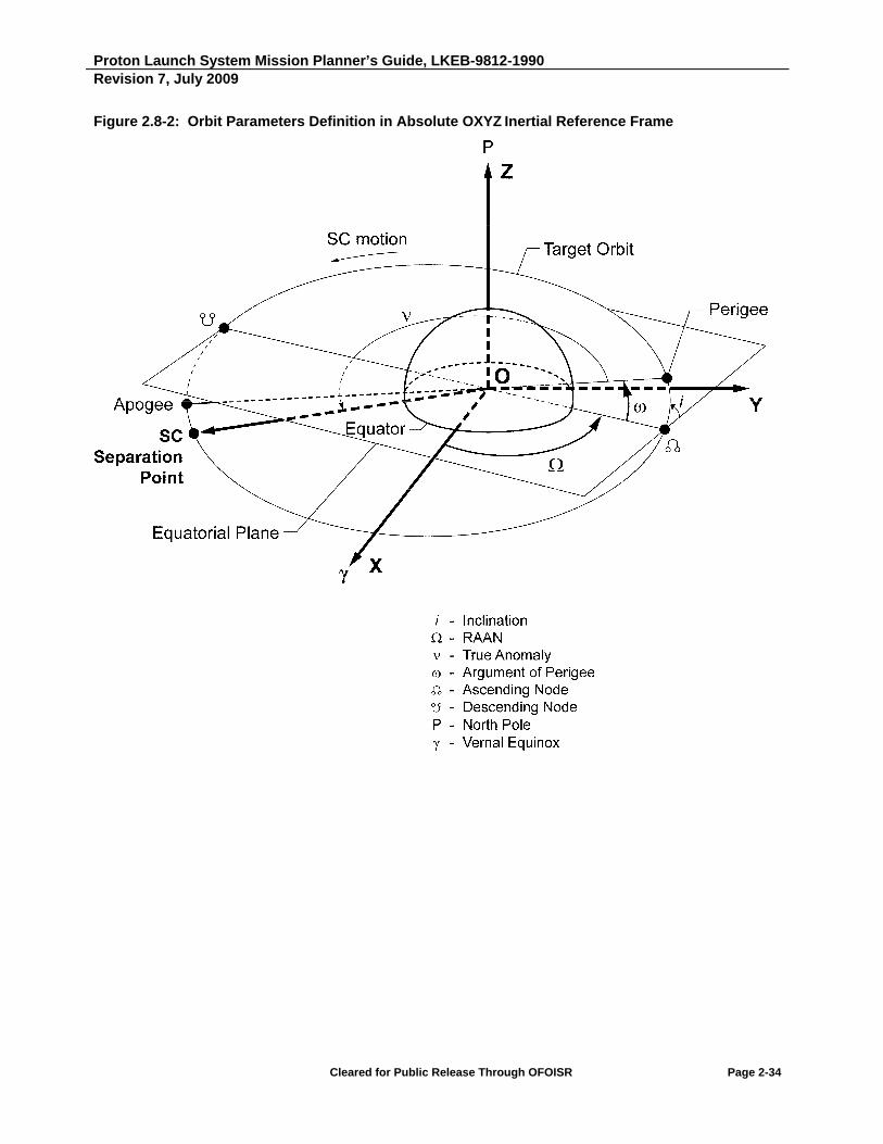
Proton Launch System Mission Planner’s Guide, LKEB-9812-1990 Revision 7, July 2009
Cleared for Public Release Through OFOISR Page 2-34
Figure 2.8-2: Orbit Parameters Definition in Absolute OXYZ Inertial Reference Frame

Proton Launch System Mission Planner’s Guide, LKEB-9812-1990 Revision 7, July 2009
Cleared for Public Release Through OFOISR Page 2-35
Within two days following separation, the SC contractor will provide SC derived state vector data to ILS, as shown in Table 2.8-4.
The SC contractor will provide SC rotation data about the SC X, Y and Z axes immediately after separation.
Table 2.8-4: Spacecraft-Supplied Post-Separation Data
Parameter Units
1 Epoch
Date (DD/MM/YY) and time (hr, min, sec) (GMT)
2 Semi-major axis, a km
3 Eccentricity, e --
4 Inclination, i deg
5 Right Ascension of the Ascending Node, deg
6 True Anomaly, ν deg
7 Perigee altitude, Hp km
8 Apogee altitude, Ha km
9 Argument of Perigee, deg
10 SC spin axis relative right ascension deg
11 SC spin axis declination deg
12 SC angular rate about ZSC immediately after separation deg/sec
13 SC angular rate about YSC immediately after separation deg/sec
14 SC angular rate about XSC immediately after separation deg/sec
Notes:
a) Line Item 1 date and time will be GMT (Greenwich Mean Time).
b) SC separation spin axis right ascension and declination are specified in Earth-centered coordinate system, as defined in Figure 2.8-1.
c) Data in rows 4 - 6 and in 10 are defined in absolute inertial coordinate system of a current epoch (Figure 2.8-2). The current epoch is the time of SC separation from the Breeze M Upper Stage.

Intentionally Blank

Proton Launch System Mission Planner’s Guide
SECTION 3
Spacecraft Environments


Proton Launch System Mission Planner’s Guide, LKEB-9812-1990 Revision 7, July 2009
Cleared for Public Release Through OFOISR Page 3-1
3. SPACECRAFT ENVIRONMENTS
This section provides the expected ground and flight environments that a SC may encounter during a Proton launch campaign and flight.
3.1 THERMAL/HUMIDITY
In this section, the thermal and humidity environment for the SC is defined for transportation from the Yubileiny Airfield through launch base processing, launch and separation. SC component temperatures, to be used for assessing ground and flight thermal compatibility, will be determined by analysis using a Customer-supplied SC thermal model.
3.1.1 SC Ground Thermal and Humidity Environment
Ambient temperatures at the Baikonur Cosmodrome are provided in Table 3.1.1-1. Facility and transportation temperatures and relative humidity are provided in Table 3.1.1-2. During transport, the SC is air-conditioned either by Customer-provided air conditioning equipment or by a railcar-mounted thermal control unit. While on the pad, thermal control is provided by the Air Thermal Mode Control System (ATMCS) and/or the Liquid Thermal Mode Control System (LTMCS).
Table 3.1.1-1: Ambient Temperatures at the Baikonur Cosmodrome
Month Maximum (C) Minimum (C)
January 3 -40
February 0 -37
March 10 -27
April 22 -12
May 33 0
June 41 8
July 44 9
August 41 8
September 35 2
October 27 -12
November 20 -31
December 12 -38

Proton Launch System Mission Planner’s Guide, LKEB-9812-1990 Revision 7, July 2009
Cleared for Public Release Through OFOISR Page 3-2
Table 3.1.1-2: SC Thermal and Humidity Environment
# Location/Event Item
Temperature(C)
Relative Humidity**
(%) Temperature Control
Min. Max. Min. Max.
1 SC Container Inlet air to container
15 30 30 60 Thermal control railcar supplied by KhSC provides flow rate of 2000 to 8000 m3/hr. Monitoring of the temperature environment in SC container is the SCC’s responsibility.
2 Container cleaning and storage area, Building 92A-50 (Hall 102)
SC ambient air
13 25 35 60 Building air conditioning
3 Fueling Hall, 92A-50 (Hall 103A)
SC ambient air
15 25 35 60 Building air conditioning
4 AU Integration Area, Building 92A-50 (Hall 101)
SC ambient air
17 27 35 60 Building air conditioning
5 Transportation of Integrated AU to LV Integration Area (Hall 101 to Hall 111)
SC ambient air
13 27 0.5 60 Thermal control railcar supplied by KhSC. Flow rate 8000 m3/hr.*
6 AU/LV Integration Area, Hall 111, Building 92A-50
SC ambient air
17 27 30 60 Building air conditioning. If needed, the external air conditioning unit provided by KhSC is used. Flow rate 2000 to 8000 m3/hr.*
7 Transportation of Integrated Launch Vehicle (ILV) to the US fueling area
SC ambient air
10 25 0.5 60 Thermal control railcar unit provided by KhSC. Flow rate 8000 m3/hr.*
8 Breeze M fueling station SC ambient air
10 22 0.5 60 Thermal control railcar supplied by KhSC. Flow rate 8000 m3/hr.*
9 Integrated ILV rollout to the pad
SC ambient air
13 25 0.5 60 Thermal control railcar supplied by KhSC. Flow rate 8000 m3/hr.*
10 Erection SC ambient air
10 30 0.5 60 No active temperature control is provided for 3 hours before LTMCS activation.
11 On-pad with air-conditioning by ATMCS
SC ambient air
13 25 0.5 60 Air-conditioning by launch pad ATMCS. Flow rate 5000 to 13000 m3/hr.*
12 On-pad with thermal conditioning by LTMCS
SC ambient air
10 30 0.5 60 LTMCS temperature control panels in fairing.
13 Launch abort SC ambient air
10 30 0.5 60 No active temperature control is provided prior to LTMCS activation.
*The temperature is to be preset jointly by KhSC and the SCC taking into account the SC and LV thermal environment in specific weather conditions and maintained accurate to 2C.
**If relative humidity becomes <35%, operations in the vicinity of the SC (and under PLF after SC encapsulation) are permitted only after coordination with the SCC.

Proton Launch System Mission Planner’s Guide, LKEB-9812-1990 Revision 7, July 2009
Cleared for Public Release Through OFOISR Page 3-3
3.1.1.1 Thermal Control During SC Preparation
SC thermal control occurs during the following phases of launch operations:
- SC arrival. If needed, an external air conditioning unit can be used to supply conditioned air for the SC in the SC container from arrival at Yubileiny Airfield through transport by rail to Building 92A-50, Payload Processing Facility (PPF).
- SC operations. SC preparations, SC fueling and integration with the Ascent Unit (AU) rely upon the building air conditioning system in Building 92A-50.
- Mating of the AU to Proton. Transportation of the AU to Hall 111 for mating to the lower three stages relies upon an external air conditioning unit.
- AU thermal pre-conditioning before transportation to the fueling station. (Pre-conditioning is conducted based on the weather forecast for the transportation day and begins approximately 12 hours prior to transportation. The AU is protected by a thermal cover.)
- Transportation of the LV with the integrated AU to the Breeze M fueling station.
- Breeze M fueling. KhSC’s external air conditioning system is used and it operates in a closed-cycle mode.
- Thermal pre-conditioning before Integrated LV transportation to the pad.
- Integrated LV transportation to the pad.
3.1.1.2 Thermal Control at Launch Pad
An external thermal insulation shroud is placed around the fairing prior to pad rollout to provide additional insulation during the erection of the LV on the pad when there is no active air conditioning. During transportation to the pad, conditioned air is provided to the SC from the thermal control railcar. At the pad, the air conditioning is disconnected and the LV is erected.
Installation of the Integrated LV on the pad takes up to five hours before rollup of the Mobile Service Tower (MST) and reconnection of the air conditioning. For the first 2.5 to 3 hours of this process, there is no active temperature control provided, and the internal AU thermal environment is maintained by the PLF thermal cover and insulation. If thermal control is needed during the remaining 2 to 2.5 hours before MST rollup, the LTMCS can be connected and used.
After the MST is brought up to the LV, the pad ATMCS is connected and the thermal cover is removed. A thermal analysis is performed to verify that under worst-case ambient conditions, the SC temperature will not exceed allowable temperature limits during the erection process.

Proton Launch System Mission Planner’s Guide, LKEB-9812-1990 Revision 7, July 2009
Cleared for Public Release Through OFOISR Page 3-4
The on-pad air conditioning system remains active 24 hours a day until approximately 1 hour 50 minutes prior to launch, when preparations are begun for MST rollback. To provide thermal conditioning of the PLF after MST rollback, a liquid thermal control system is provided in the PLF. This system is the LTMCS, mentioned previously, and consists of radiators mounted on the PLF inside wall and connected to the thermal control system in the launch pad complex. The LTMCS is activated 3 hours 50 minutes prior to launch. The ATMCS and LTMCS operate in parallel from L-3h 50m to L-1h 50m, at which point the ATMCS is deactivated. From L-1h 50m to L-10 minutes, the LTMCS operates. Ten minutes prior to lift-off, the LTMCS is deactivated. Antifreeze fluid is drained from all lines and the lines are purged by dry nitrogen to ensure that the lines are free of liquid prior to lift-off. During this time, the AU thermal environment is maintained by the thermal properties of the AU.
In the event that the launch must be aborted, the liquid system is reactivated in five minutes and the MST rolled up to the LV to renew air conditioning within 2 hours. Two hours after a launch abort, the MST completes roll-up to the LV and the connectors to the ATMCS are remated. The ATMCS and the LTMCS operate together for 15 minutes, and then the LTMCS is deactivated. All further pad operations up to relaunch are conducted in accordance with the previously described timeline.
Table 3.1.1.2-1 summarizes this timeline for the LV from pre-conditioning prior to transport to the Breeze M fueling station through all pad operations. Figure 3.1.1.2-1 shows the AU on-pad thermal control diagram and provides a schematic of the thermal conditioning timeline.
Table 3.1.1.2-1: AU Operations Timeline at Processing Facility and Launch Pad
# Phase Duration
(hours/minutes) 1 AU thermal pre-conditioning before LV transportation to the fueling station 12 h/00 m
2 LV/AU assembly transportation to the Breeze M fueling station. Breeze M fueling. AU thermal pre-conditioning before LV/AU assembly transportation to the pad. LV/AU assembly transportation to the pad.
~ 50 h/00 m
3 Erection 5 h/00 m
4 LV on the pad; ATMCS and LTMCS ON 0 h/15 m
5 LV on the pad; ATMCS ON 96 h to 120 h
6 LV on the pad; ATMCS and LTMCS ON 2 h/00 m
7 LV on the pad; ATMCS OFF, LTMCS ON 1 h/40 m
8 LV on the pad until launch; LTMCS OFF 0 h/10 m
9 Launch abort; LTMCS OFF 0 h/05 m
10 Launch abort; LTMCS ON 2 h/00 m
11 Launch abort; ATMCS and LTMCS ON 0 h/15 m
12 LV on the pad until relaunch; ATMCS and LTMCS operating in accordance with standard timeline
variable

Proton Launch System Mission Planner’s Guide, LKEB-9812-1990 Revision 7, July 2009
Cleared for Public Release Through OFOISR Page 3-5
Figure 3.1.1.2-1: Fairing Air and Liquid Thermal Mode Control Systems Schematic and Operations Timeline

Proton Launch System Mission Planner’s Guide, LKEB-9812-1990 Revision 7, July 2009
Cleared for Public Release Through OFOISR Page 3-6
3.1.1.3 Supplemental Air Conditioning for SC Battery Charging
Supplemental SC air conditioning can be provided on the pad during SC battery charging operations as a Customer requested option. Up to 500 m3/hr can be provided through several access doors in the fairing at a temperature selectable between 10 and 16C up until the time of MST rollback, 1 hour, 50 minutes prior to launch. The air inlets can be provided in the mission-specific access doors (see Figure 3.1.1.3-1 and Figure 3.1.1.3-2), and are described in more detail in Section 4.
3.1.2 SC Flight Thermal Environment
3.1.2.1 Launch to Parking Orbit Injection
During ascent, the LV will be exposed to aerodynamic heat flux. Following PLF jettison, the SC will be exposed to solar radiation and Free Molecular Heat Flux (FMHF). A thermal analysis will be performed using the Customer-supplied SC thermal model to predict SC temperatures during this phase of the mission. The heat flux density radiated upon the SC by the internal surfaces of the PLF does not exceed 500 W/m2 from the time of launch until PLF jettison. The PLF is jettisoned at approximately 340 to 350 seconds into flight (at an altitude of 121 to 125 km or more), and the maximum FMHF does not exceed 1135 W/m2 at any time following PLF jettison.
3.1.2.2 Orbit
Following injection into parking orbit, the SC thermal environment is determined mainly by solar radiation, albedo and infrared earth radiation, and FMHF. Attitude maneuvers of the Breeze M can be programmed to provide desired sun angles for maintaining SC battery power and thermal control. An integrated thermal analysis is performed by KhSC using the SCC-supplied thermal mathematical model to determine SC temperatures as a function of time throughout the flight up to SC separation.
3.1.3 Air Impingement Velocity
The air impingement velocity on the SC surfaces within the PLF does not exceed five m/s during ground operations following encapsulation through launch. The actual value of the velocity will be determined based on mission-specific analysis.

Proton Launch System Mission Planner’s Guide, LKEB-9812-1990 Revision 7, July 2009
Cleared for Public Release Through OFOISR Page 3-7
Figure 3.1.1.3-1: SC Battery Air Conditioning System (Option 1)

Proton Launch System Mission Planner’s Guide, LKEB-9812-1990 Revision 7, July 2009
Cleared for Public Release Through OFOISR Page 3-8
Figure 3.1.1.3-2: SC Battery Air Conditioning System (Option 2)

Proton Launch System Mission Planner’s Guide, LKEB-9812-1990 Revision 7, July 2009
Cleared for Public Release Through OFOISR Page 3-9
3.2 CONTAMINATION ENVIRONMENT
3.2.1 Ground Contamination Control
The contamination environment around the SC is controlled by use of ISO Class 8 cleanroom facilities and strict control of material cleanliness of flight hardware in proximity to the SC. During transportation using KhSC-provided air conditioning systems and while on the pad, air is filtered to provide at least ISO Class 8 particle content. Air cleanliness is monitored regularly in all areas where the SC is present to ensure particle count levels are maintained within specification. In addition, witness plates can be mounted inside the fairing following encapsulation to monitor particle fallout inside the fairing up to L-1 day. The ground contamination environment around the SC meets the cleanliness levels specified in Table 3.2.1-1.
Table 3.2.1-1: Ground Contamination Environment
Location/Event Cleanliness Level
Required* Comments
SC container ISO Class 8 ILS/KhSC-supplied conditioned air
SC processing facilities (Building 92A-50) ISO Class 8 Facility air conditioning
Encapsulated in PLF during transportation, Breeze M fueling and battery charging
ISO Class 8 Payload encapsulated, filtered air provided
Erection ISO Class 8 Payload compartment sealed
On-pad with air conditioning through umbilical ISO Class 8 Filtered air provided
On-pad following removal of air conditioning umbilical ISO Class 8 Payload compartment sealed
* Per ISO 14644-1
3.2.2 In-Flight Contamination Control
The LV systems are designed to preclude in-flight contamination of the SC. The LV pyrotechnic devices near the SC used for PLF jettison and SC separation have sealed gas chambers and do not release significant contamination to the outside environment. The PLF liquid thermal control system pipes are sealed by automatic valves, which close at PLF jettison. The third stage retrorocket plume does not result in any significant particle contact with the SC due to its position on the aft end of the third stage and the orientation of the retrorocket axis 15 degrees away from the LV longitudinal axis. The Breeze M attitude control thrusters are located on the aft section of the central unit and oriented perpendicular to the Breeze M longitudinal axis (worst case), such that the plume does not contact the SC while the SC is attached to the Breeze M.
Following SC separation, the Breeze M maintains the attitude specified at spacecraft separation until the SC is a safe distance away. After an appropriate amount of time, the Breeze M performs a Collision and Contamination Avoidance Maneuver (CCAM).

Proton Launch System Mission Planner’s Guide, LKEB-9812-1990 Revision 7, July 2009
Cleared for Public Release Through OFOISR Page 3-10
3.3 PRESSURE
3.3.1 Payload Compartment Venting
During ascent, the payload compartment is vented through four to six venting orifices distributed equally about the cylindrical portion of the fairing. Maximum rate of pressure drop in the fairing will not exceed 3.5 kPa/s. A representative pressure drop profile inside the fairing during flight is shown in Figure 3.3.1-1.
The archimedes volume of the SC to be taken into account for the venting analysis will be provided by the Customer.
Figure 3.3.1-1: Nominal Payload Compartment Internal Pressure Change During Ascent
Time
(s) Atmosphere Inside Fairing
0 100.11 100.11
10 97.64 98.37
20 89.63 90.92
30 76.32 78.38
40 59.42 62.92
50 41.54 45.47
60 25.76 29.56
70 14 18.51
80 6.9 11.35
90 3.12 6.95
100 1.31 4.25
110 0.53 2.6
120 0.21 1.59
Pressure (kPa)

Proton Launch System Mission Planner’s Guide, LKEB-9812-1990 Revision 7, July 2009
Cleared for Public Release Through OFOISR Page 3-11
3.4 MECHANICAL LOADS
The SC is subject to various types of mechanical loads due to transportation and handling during the launch campaign, as well as due to the various flight events following lift-off. These mechanical loads are maximum expected environments at the SC interface. Mission peculiar updates to these environments may be further specified in the SC/LV Interface Control Document (ICD). In this case, the ICD levels supersede the PMPG values and are applicable only to the specific mission defined.
The PMPG environments are divided into separate loading types: quasi-static loads, sine and random vibration loads, acoustic loads, and shock loads. Operating (maximum expected) environments for SC ground processing and flight are presented in the sections below. These maximum expected environments do not include safety factors typically employed to determine actual environmental requirements, such as qualification or proto-flight levels during static or dynamic tests. Requirements for various kinds of testing are presented in Section 3.4.5.
3.4.1 Quasi-Static Loads at the SC Separation Plane
The operating loads at the SC separation plane are specified using quasi-static accelerations and are determined using the following relations:
CGlateralSCbend
lateralSCshear
axialSCaxial
LamM
amQ
amN
where:
on.acceleratistatic -quasi lateral the is
on,acceleratistatic -quasi axial the is
position, SC suitable a for CG SC the to plane separation the from distance the is
operation, given a for mass SC possible maximum the is
moment, bending the is
force, shear lateral the is
force, axial the is
lateral
axial
CG
SC
bend
shear
axial
a
a
L
m
M
Q
N
For the SC primary structure, the equivalent linear loads along the LV interface serve as the LV compatibility criterion. These loads consider the combined action of longitudinal force and bending moment. The equivalent linear load is calculated using the following relation:
D
MNq bendaxial
4
where:
ring. interface the of diameter the is
moment, bending the is
force, axial the is
load, linear equivalent the is
D
M
N
q
bend
axial

Proton Launch System Mission Planner’s Guide, LKEB-9812-1990 Revision 7, July 2009
Cleared for Public Release Through OFOISR Page 3-12
The interface between the SC and LV shall withstand an equivalent linear load that corresponds to all combinations of quasi-static accelerations, with an appropriate safety factor.
In compiling a test program for a SC/LV interface static environment, the non-uniformity of linear load distribution along the circumference of the interface ring must be considered. If the SC/LV interface is modeled by one six-degree node in the SC dynamic model, then the developer of the SC dynamic mode shall calculate the non-uniformity factor with due regard for the flexibility of the LV adapter system. When the interface is modeled with several nodes (i.e., the interface is statically indeterminate), the non-uniformity factor is calculated on the basis of coupled dynamic models of the SC and LV (or LV adapter system).
3.4.1.1 Ground Operations Environment
SC ground operations include handling operations and operations related to SC transportation, both locally in a container and as part of the AU and integrated launch vehicle as shown in Figure 3.4.1.1-1.
Figure 3.4.1.1-1: SC Transportation in the Manufacturer's SC Container or in a KhSC Container, AU Transportation, and Proton-M LV Transportation

Proton Launch System Mission Planner’s Guide, LKEB-9812-1990 Revision 7, July 2009
Cleared for Public Release Through OFOISR Page 3-13
Quasi-static accelerations in the transport unit reference frame, which are used to determine the operating environment in the SC separation plane during ground operations, are shown in Table 3.4.1.1-1.
Quasi-static accelerations act simultaneously along the X, Y, and Z axes. Quasi-static accelerations along the Y axis include the acceleration of gravity (1g) in all cases.
Table 3.4.1.1-1: Quasi-Static SC Accelerations During Transportation and Handling Operations
Operations
Quasi-Static Accelerations (g)
X-axis Y-axis Z-axis
Standalone SC transport in its transport container (a, b, d) 1.00 1.00 1.00 0.40
SC transportation as part of the AU (a, d) 0.50 1.00 0.50 0.40 SC transportation as part of the integrated LV (a, d) 0.40 1.00 0.30 0.15 Handling operations with the SC and with the container containing the SC (c, e)
0.15 1.00 0.50 -
Notes:
a) During transportation, the employed reference frame is linked to the axes of the transportation unit (Fig. 3.4.1.1-1). Specifically:
- The X axis coincides with the direction of motion
- The Y axis coincides with the direction of the force of gravity
- The Z axis completes a right-handed coordinate system
b) The SC is not loaded with propellant. The container is mounted in such a way that its principal dimension is directed along the direction of motion.
c) The following reference frame is used for handling operations
-The Y axis coincides with the direction of the force of gravity
-The X axis is directed in any transverse direction
d) 22; zylateralxaxial aaaaa
e) aaxiall = ax; alateral = ay

Proton Launch System Mission Planner’s Guide, LKEB-9812-1990 Revision 7, July 2009
Cleared for Public Release Through OFOISR Page 3-14
3.4.1.2 Flight Environments
Loads act on a SC in flight, attaining maximum values in the lateral direction during LV lift-off and in the axial direction during first stage separation.
Quasi-static accelerations for determining the operating environment along the SC separation plane during flight are shown in graphical and tabular form in Figure 3.4.1.2-1 and Table 3.4.1.2-1.
In a conservative assessment of the environment, it is assumed that quasi-static accelerations in the longitudinal and lateral directions act simultaneously (i.e., in the worst case).
The environment shown is the most probable and is refined on the basis of a Coupled Loads Analysis (CLA) using a combined dynamic model of the SC and LV.
The maximum limit equivalent linear load obtained from the CLA should not exceed the maximum equivalent linear load corresponding to all combinations of quasi-static accelerations (Fig. 3.4.1.2-1).

Proton Launch System Mission Planner’s Guide, LKEB-9812-1990 Revision 7, July 2009
Cleared for Public Release Through OFOISR Page 3-15
Figure 3.4.1.2-1: Limit Quasi-Static Accelerations on the SC During Flight
-6
-5
-4
-3
-2
-1
0
1
2
3
4
5
-2 -1 0 1 2
Lo
ng
itu
din
al A
ccel
erat
ion
(g)
Lateral Acceleration (g)
Lighter SC (≤ 6000 kg)
Heavier SC (6000 - 7500 kg)
Table 3.4.1.2-1: Limit Quasi-Static Accelerations on the SC During Flight
Design Case
Quasi-Static Accelerations (g)
aaxial*
alateral mSC ≤ 6000 kg 6000 kg ≤ mSC ≤ 7500 kg
max min max min Lift-off -0.4 -2.60 -0.10 -2.60 ± 1.70 Maximum dynamic pressure, ( max) -2.20 ± 1.30 Stage 1/2 separation 3.2 -4.2 3.70 -5.10 ± 0.90 Stage 2/3 separation -0.30 -3.00 -0.30 -3.00 ± 0.30 Stage 3/4 separation -0.30 -2.80 -0.30 -2.80 ± 0.30
* "+" denotes tension; "-" denotes compression

Proton Launch System Mission Planner’s Guide, LKEB-9812-1990 Revision 7, July 2009
Cleared for Public Release Through OFOISR Page 3-16
3.4.2 Sine and Random Vibration Loads
3.4.2.1 Random Vibrations During Ground Operations
During ground transportation rail transport, the SC is exposed to random vibrations. The random vibration levels for different transport configurations are shown in Figures 3.4.2.1-1 and 3.4.2.1-2. These levels may be considered maximum limit load environments, based on a statistical limit of 99% probability. The duration that is specified is not the actual time of transport, but is an equivalent duration of exposure to maximum load, to which all existing transportation vibration levels are reduced given a log–normal distribution.

Proton Launch System Mission Planner’s Guide, LKEB-9812-1990 Revision 7, July 2009
Cleared for Public Release Through OFOISR Page 3-17
Figure 3.4.2.1-1: Random Vibration Levels-Ground Transportation by Rail, SC in Container and SC Attached to AU
0.00E+00
5.00E-04
1.00E-03
1.50E-03
2.00E-03
2.50E-03
3.00E-03
3.50E-03
1 10 100
Po
we
r S
pe
ctr
al D
en
sit
y (g
2 /H
z)
Frequency (Hz)
X-X
Y-Y
Z-Z
Notes:
X-X Y-Y Z-Z The X-axis is oriented in the direction of movement.
2 0.000075 0.000150 0.000150 The Y-axis is directed vertically, parallel to the gravity field.
4 0.000575 0.003300 0.000330 The Z-axis completes a right-handed coordinate system.
8 0.002000 0.003200 0.00066010 0.000600 0.003200 0.00080014 0.000280 0.000833 0.00033020 0.000275 0.000150 0.00032025 0.000275 0.000150 0.00031030 0.000275 0.000150 0.00030035 0.000500 0.000150 0.00018540 0.000180 0.000150 0.000037 * Durations are as follows:
45 0.000125 0.000150 0.000037
SC and container transport from Yubileiny to Building 92А-50 in 60 minutes.
50 0.000125 0.000150 0.000037AU transport from Hall 101 to Hall 111 of Building 92A-50 in 5 minutes.
Duration (minutes)
* * *
PSD (g2/Hz)
- The transportation velocity is less than or equal to 15 km/hr (SC in container) or 5 km/hr (as part of AU from Building 92A-50)
- The random vibration values shown are those at the base of the container when the SC is transported by itself, and those at the SC/adapter interface for transportation as part of the AU.
Frequency (Hz)

Proton Launch System Mission Planner’s Guide, LKEB-9812-1990 Revision 7, July 2009
Cleared for Public Release Through OFOISR Page 3-18
Figure 3.4.2.1-2: Random Vibration Levels - ILV Ground Transportation by Rail
0.00E+00
2.00E-04
4.00E-04
6.00E-04
8.00E-04
1.00E-03
1.20E-03
1.40E-03
1.60E-03
1.80E-03
2.00E-03
1 10 100
Po
we
r S
pe
ctr
al D
en
sit
y (g
2 /H
z)
Frequency (Hz)
X-X
Y-Y
Z-Z
Notes:
X-X Y-Y Z-Z The X-axis is oriented in the direction of movement.
2 0.0002 0.0002 0.0002 The Y-axis is directed vertically, parallel to the gravity field.
4 0.0002 0.0002 0.0002 The Z-axis completes a right-handed coordinate system.
8 0.0002 0.0002 0.0002 Transportation velocity <5 km/hr.
10 0.0002 0.0002 0.0002 The random vibration values shown are those at the
14 0.0002 0.0020 0.0002 SC/PLA interface.
20 0.0010 0.0001 0.001025 0.0001 0.0001 0.000130 0.0001 0.0001 0.000135 0.0003 0.0001 0.000140 0.0001 0.0001 0.000145 0.0001 0.0001 0.000150 0.0001 0.0001 0.0001
Duration (minutes)
10 10 10
PSD (g2/Hz)Frequency (Hz)

Proton Launch System Mission Planner’s Guide, LKEB-9812-1990 Revision 7, July 2009
Cleared for Public Release Through OFOISR Page 3-19
3.4.2.2 Equivalent Sinusoidal Environments During Flight
At launch, when the propellant valves of the first stage engines are opened, reactive forces act on the liquid propellant in the tanks (for approximately 0.1 sec) causing LV longitudinal oscillations on the elastic pad supports. Prevailing oscillation frequencies are approximately 4 Hz with amplitudes of 0.3 g.
The engines operate at a preliminary thrust level that remains constant for approximately 1.6 sec. During this period, the LV experiences flexible bending oscillations brought about by uneven thrust among the six engines and unequal off-loading of the pad supports. The prevailing frequencies are 5 to 7 Hz.
Longitudinal flexible body oscillations appear simultaneously with frequencies ranging from 5 to 15 Hz. They are magnified as the engines are throttled up to full thrust within 0.5 sec as the LV leaves the pad.
During first stage flight, lateral dynamic loads are generated by wind gusts superimposed on steady-state wind loads generated by the jet stream. LV longitudinal flexible oscillations are produced at 10 to 12 Hz by the natural random pulsation of the engine thrust. There is no pogo phenomenon. The maximum value of these oscillations based on telemetry measurements is 0.35 g.
From 0.5 to 0.6 seconds before first stage cutoff, the four second stage engines start up and gain preliminary thrust. Because of the uneven thrust of the four engines, lateral reaction forces are generated, causing lateral flexible oscillations of the LV body. These oscillations are influenced additionally by the first stage engines reacting to control system commands. The first stage cutoff is characterized by an abrupt decay from 90% to 20% within 0.03 sec, which causes significant flexible longitudinal oscillations of the LV second stage, driven by the preliminary thrust of its own engines. The oscillations are additionally magnified due to the increase in thrust to 100%. These oscillations damp out within about 3 seconds.
Dynamic loads occurring during the propulsive events following first/second stage separation are enveloped by the preceding events.
The above dynamic load environment can be represented by the quasi-sinusoidal vibration environment applied at the SC/LV interface plane shown in Figure 3.4.2.2-1. This can be considered a flight limit load environment.
It must be noted that response of SC primary structure at frequencies significantly lower than the frequency of the fundamental longitudinal mode of the SC will be equivalent to the static load applied. Since the minimum frequency of the SC longitudinal mode is required to be at least 25 Hz (see Section 3.4.1.1), the response of primary structure to longitudinal (i.e., thrust axis) excitations below 15 Hz shall be considered to be quasi-static in nature. Such loading will then be qualified from static testing results. The user should consider the worst-case combination of QSL in accordance with Figure 3.4.1.2-1.
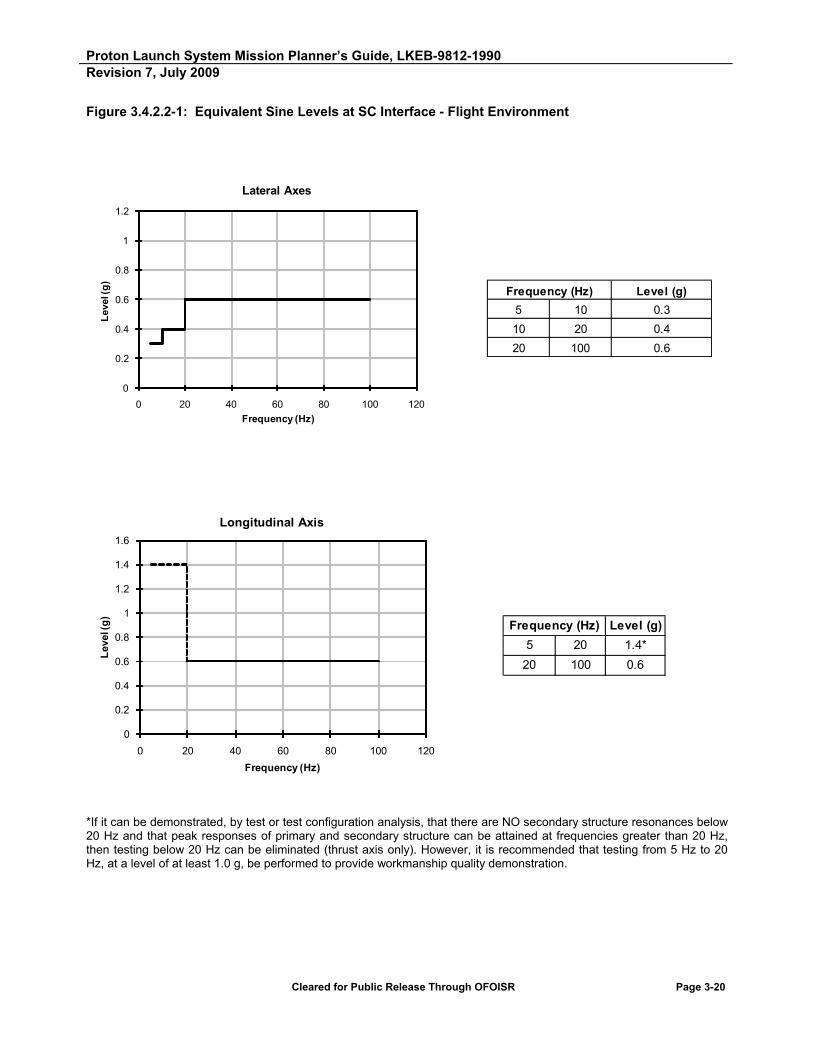
Proton Launch System Mission Planner’s Guide, LKEB-9812-1990 Revision 7, July 2009
Cleared for Public Release Through OFOISR Page 3-20
Figure 3.4.2.2-1: Equivalent Sine Levels at SC Interface - Flight Environment
Frequency (Hz) Level (g)
5 10 0.3
10 20 0.4
20 100 0.6
0
0.2
0.4
0.6
0.8
1
1.2
0 20 40 60 80 100 120
Lev
el (g
)
Frequency (Hz)
Lateral Axes
Frequency (Hz) Level (g)
5 20 1.4*
20 100 0.6
0
0.2
0.4
0.6
0.8
1
1.2
1.4
1.6
0 20 40 60 80 100 120
Lev
el (g
)
Frequency (Hz)
Longitudinal Axis
*If it can be demonstrated, by test or test configuration analysis, that there are NO secondary structure resonances below 20 Hz and that peak responses of primary and secondary structure can be attained at frequencies greater than 20 Hz, then testing below 20 Hz can be eliminated (thrust axis only). However, it is recommended that testing from 5 Hz to 20 Hz, at a level of at least 1.0 g, be performed to provide workmanship quality demonstration.
Proton Launch System Mission Planner’s Guide, LKEB-9812-1990 Revision 7, July 2009
Cleared for Public Release Through OFOISR Page 3-21
3.4.3 Acoustic Loads
The launch acoustic loads arise from acoustic sound waves generated by the supersonic jets from the first stage engine nozzles being diverted by the launch pad and flame deflectors. At transonic velocity and maximum aerodynamic drag, acoustic loads are caused by aerodynamic pressure pulsation effects on the PLF surface. The peak acoustic loads occur for a period no longer than 5 seconds at lift-off. Peak acoustic load characteristics normalized to the threshold pressure of 20 µPa are shown in Figure 3.4.3-1. These levels should be taken as the 95/50 statistical levels, taking into account Proton Breeze M launch history to date.
3.4.4 Shock Loads
Shock loads act on the SC during firing of pyro charges during fairing jettison, Proton LV staging, jettisoning of the Breeze M auxiliary propellant tanks, SC separation from the Proton integrated launch vehicle, etc. The maximum shock load levels occur during SC separation from the adapter, and depend on the type of separation system, as well as the tension of the clampband or the bolts for a 4 hard-point interface.
Figure 3.4.4-1 and Table 3.4.4-1 present the shock spectrum values in the 100 to 10,000 Hz frequency range for an adapter system with 937 mm, 1194 mm, and 1666 mm diameter interfaces, equipped with a clampband separation system, as well as for an adapter system with a 1664 mm diameter, 4 hard point interface. A description of various adapter/clampband systems is given in Section 4.1.5. The clampband tension for different types of clampbands varies between 30 kN and 56 kN. The shock loads in Figure 3.4.4-1 are specified for a plane located 25 mm to 120 mm from the SC separation plane, on the SC side.
The specified loads shown are based on local tests by the adapter system manufacturers (specifically, RUAG, CASA, and KhSC), and have been confirmed by shock load measurements during fitchecks of standard SC.

Proton Launch System Mission Planner’s Guide, LKEB-9812-1990 Revision 7, July 2009
Cleared for Public Release Through OFOISR Page 3-22
Figure 3.4.3-1: Limit Acoustic Environment
100.0
110.0
120.0
130.0
140.0
10 100 1000 10000
Lev
el (d
B)*
Frequency (Hz)
1/3 Octave Band
Full Octave Band**
*Acoustic environments are defined with respect to a reference level of 20 mPa. **Testing is recommended to 1/3 octave; full octave data are provided for information purposes.
1/3 Octave Band Full Octave Band**25 117.0
31.5 123.040 127.050 126.563 127.880 131.6
100 132.4125 131.3160 132.1200 132.1250 132.1315 129.9400 129.0500 127.0630 124.0800 121.01000 119.01250 117.01600 114.52000 112.52500 111.03150 109.04000 108.05000 107.06300 105.58000 104.0
10000 103.5OASPL 141.5 141.5
Center Frequency (Hz)
Acoustic Levels on Spacecraft (dB)*
128.8
134.0
136.7
112.8
109.2
136.3
131.9
124.1
117.7
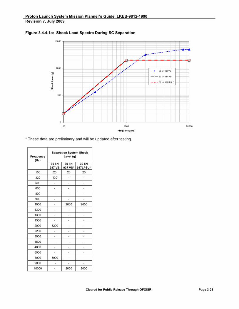
Proton Launch System Mission Planner’s Guide, LKEB-9812-1990 Revision 7, July 2009
Cleared for Public Release Through OFOISR Page 3-23
Figure 3.4.4-1a: Shock Load Spectra During SC Separation
10
100
1000
10000
100 1000 10000
Sh
ock
Lev
el (g
)
Frequency (Hz)
30 kN 937 VB
30 kN 937 VS*
30 kN 937LPSU*
* These data are preliminary and will be updated after testing.
100 20 20 20
320 130 - -
500 - - -
600 - - -
800 - - -
900 - - -
1000 - 2000 2000
1300 - - -
1330 - - -
1500 - - -
2000 3200 - -
2200 - - -
3000 - - -
3500 - - -
4000 - - -
6000 - - -
8000 5000 - -
9000 - - -
10000 - 2000 2000
Frequency (Hz)
30 kN 937LPSU*
30 kN 937 VS*
30 kN 937 VB
Separation System Shock Level (g)
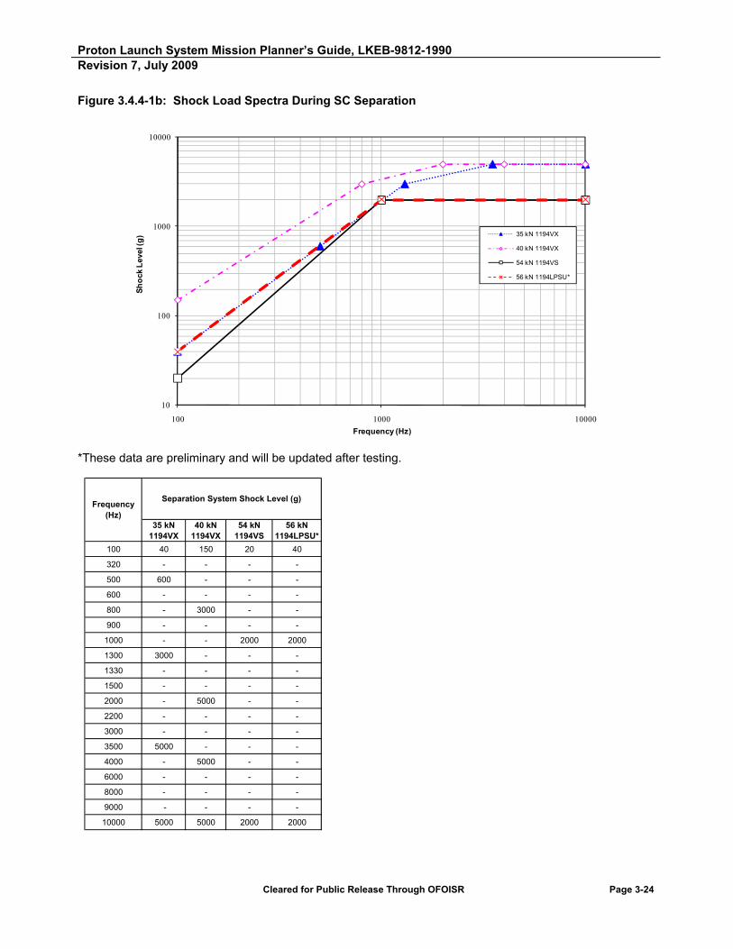
Proton Launch System Mission Planner’s Guide, LKEB-9812-1990 Revision 7, July 2009
Cleared for Public Release Through OFOISR Page 3-24
Figure 3.4.4-1b: Shock Load Spectra During SC Separation
10
100
1000
10000
100 1000 10000
Sh
ock
Lev
el (g
)
Frequency (Hz)
35 kN 1194VX
40 kN 1194VX
54 kN 1194VS
56 kN 1194LPSU*
*These data are preliminary and will be updated after testing.
100 40 150 20 40
320 - - - -
500 600 - - -
600 - - - -
800 - 3000 - -
900 - - - -
1000 - - 2000 2000
1300 3000 - - -
1330 - - - -
1500 - - - -
2000 - 5000 - -
2200 - - - -
3000 - - - -
3500 5000 - - -
4000 - 5000 - -
6000 - - - -
8000 - - - -
9000 - - - -
10000 5000 5000 2000 2000
Frequency (Hz)
54 kN 1194VS
40 kN 1194VX
56 kN 1194LPSU*
35 kN 1194VX
Separation System Shock Level (g)

Proton Launch System Mission Planner’s Guide, LKEB-9812-1990 Revision 7, July 2009
Cleared for Public Release Through OFOISR Page 3-25
Figure 3.4.4-1c: Shock Load Spectra During SC Separation
10
100
1000
10000
100 1000 10000
Sh
ock
Lev
el (g
)
Frequency (Hz)
30 kN 1666V
40 kN 1666VS*
40 kN 1666LPSU*
* These data are preliminary and will be updated after testing.
100 150 40 40
320 - - -
500 - - -
600 - - -
800 - - -
900 3000 - -
1000 - 2000 2000
1300 - - -
1330 - - -
1500 - - -
2000 - - -
2200 - - -
3000 3000 - -
3500 - - -
4000 - - -
6000 3500 - -
8000 - - -
9000 3500 - -
10000 4000 2000 2000
Frequency (Hz)
40 kN 1666LPSU*
40 kN 1666VS*
30 kN 1666V
Separation System Shock Level (g)

Proton Launch System Mission Planner’s Guide, LKEB-9812-1990 Revision 7, July 2009
Cleared for Public Release Through OFOISR Page 3-26
Figure 3.4.4-1d: Shock Load Spectra During SC Separation
10
100
1000
10000
100 1000 10000
Sh
ock
Lev
el (g
)
Frequency (Hz)
1664 HP
Separation System Shock
Level (g)
160 kN1664 HP
100 30
320 -
500 -
600 -
800 -
900 -
1000 -
1300 -
1330 -
1500 -
2000 -
2200 -
3000 1600
3500 -
4000 -
6000 -
8000 -
9000 -
10000 8000
Frequency (Hz)

Proton Launch System Mission Planner’s Guide, LKEB-9812-1990 Revision 7, July 2009
Cleared for Public Release Through OFOISR Page 3-27
Table 3.4.4-1: Shock Load Spectra During SC Separation F
req
uen
cy (
Hz)
Accelerations Above the SC Separation Plane (g)
937 VB Band
tension 30 kN
937 VS* Band
tension 30 kN
937LPSU* Band
tension 30 kN
1194VXBand
tension 35 kN
1194VXBand
tension40 kN
1194VSBand
tension54 kN
1194LPSU*Band
tension 56 kN
1666VBand
tension30 kN
1666VS* Band
tension 40 kN
1666LPSU*Band
tension 40 kN
813МDТВ10Bolt
tension 160 kN
100 20 20 20 40 150 20 40 150 40 40 30
320 130 - - - - - - - -
500 - - - 600 - - - - - -
600 - - - - - - - - -
800 - - - 3000 - - - - - -
900 - - - - - 3000 - - -
1000 - 2000 2000 2000 2000 - 2000 2000 -
1300 - - - 3000 - - - - - -
1330 - - - - - - - - -
1500 - - - - - - - - -
2000 3200 - - 5000 - - - - - -
2200 - - - - - - - - -
3000 - - - - - 3000 - - 1600
3500 - - - 5000 - - - - - -
4000 - - - 5000 - - - - - -
6000 - - - - - 3500 - - -
8000 5000 - - - - - - - -
9000 - - - - - 3500 - - -
10000 - 2000 2000 5000 5000 2000 2000 4000 2000 2000 8000
Note: * These data are preliminary and will be updated after testing.

Proton Launch System Mission Planner’s Guide, LKEB-9812-1990 Revision 7, July 2009
Cleared for Public Release Through OFOISR Page 3-28
3.4.5 Environmental Test Requirements
The SC environmental test program is intended to verify that the SC is capable of withstanding the maximum expected environments defined in Section 3.4, with due regard to applied safety factors.
Static testing of the primary structure is required as a qualification of the structure for flight for first-of-a-kind SC. Demonstration of the SC secondary structures ability to withstand dynamic loads induced by flight events and ground transportation is required for qualification and acceptance of the SC design. Testing is required for hardware that does not have a design margin of safety greater than 2.0 with respect to the maximum expected environment.
Test levels are defined as follows:
Qualification Level Test - Qualification level test is performed on structural test articles that will not be used for flight. This test is used to support early development or verification of preliminary design of new SC hardware.
Proto-Qualification Level Test - Proto-qualification level test is performed on flight hardware for verification of final design and is generally used for first-of-a-kind SC.
Acceptance Level Test - Acceptance level test is performed as workmanship verification for flight hardware and is generally used for follow-on SC that have already been qualified.
The test level is determined by the SC classification: follow-on or first-of-a-kind. The definitions of these SC classifications are as follows:
First-Of-A-Kind SC - First-of-a-kind SC include all SC bus platforms that have not been qualified to Proton ground and flight environments. SC that have flown on the Proton with a bus structure that has been modified in such a manner as to affect critical SC modal responses are considered first-of-a-kind.
Follow-On SC - Previously qualified SC configurations that have demonstrated margins consistent with the levels defined in this document are classified as follow-on missions. SC configurations that have identical primary bus structures to missions previously flown on Proton are also considered as follow-on. These SC configurations shall have no hardware modifications that affect the response of (1) SC primary modes (primary structure, bus components, tanks), and (2) major subsystem assemblies (i.e., antenna feeds/reflectors, solar arrays, bus panels). Secondary hardware that has changed from previous SC configurations may be tested at the component level provided that the interface boundary and associated inputs are representative of the system response.

Proton Launch System Mission Planner’s Guide, LKEB-9812-1990 Revision 7, July 2009
Cleared for Public Release Through OFOISR Page 3-29
In order to classify a mission as follow-on, a list of previous qualification test experience and a description of all major subassemblies shall be provided by the SC manufacturer outlining what components are new/modified. In addition, a comparison of new/old system level frequencies shall be provided to determine the extent of the hardware updates. The determination of follow-on versus first-of-a-kind shall be determined jointly by ILS and the SC Customer.
Tests levels, durations, and margins are defined as they apply to first-of-a-kind and follow-on missions. Table 3.4.5-1 outlines test requirements for both qualification and acceptance level tests for each of the loading environments.
The following paragraphs define the specific loading environment and associated test requirements in more detail.
Table 3.4.5-1: Test Requirements Summary
Quasi-Static
Loads Sine Vibe Random Vibe1 Acoustic Shock2
Qualification/Protoflight (First-of-a-Kind)
X X X X X
Acceptance (Follow-on) X X
1. May be demonstrated by a fatigue analysis and/or test. 2. Consistent with shock test description in Section 3.4.5.5.
3.4.5.1 Acoustic Test Requirements
For newly designed hardware, system level acoustic testing is performed at protoflight or qualification levels to qualify the SC design. The test should use a SC adapter that represents the flight adapter stiffness to avoid over constraining the LV/SC interface. Follow-on SC are also tested at the system level to verify material properties and workmanship at maximum expected flight levels.
The SC test requirements are provided in Table 3.4.5.1-1.
Table 3.4.5.1-1: Acoustic Test Requirements
Type of Test Levels Test Duration (seconds)
Qualification Limit levels + 3 dB 120
Proto-Qualification Limit levels +3 dB 60
Acceptance Not less than operational levels, in accordance with Figure 3.4.3-1 in each band
60

Proton Launch System Mission Planner’s Guide, LKEB-9812-1990 Revision 7, July 2009
Cleared for Public Release Through OFOISR Page 3-30
The SC test shall be configured such that the average of all control microphones represents a good average of the acoustic environment around the entire SC. Levels attained shall be such that the average of all control microphones shall be greater than or equal to the levels shown in Table 3.4.5.1-1 in each band and at each moment in time during the entire test duration. As a consequence, the SC manufacturer has to set the control levels such that with test tolerances, this minimum criteria is attained.
The SC manufacturer may decide to test to single octave equivalent of the levels shown in Figure 3.4.3-1. This is possible on a mission-specific basis with specific approval from ILS.
3.4.5.2 Static Test Requirements
The static test must demonstrate the capability of the structure to withstand the worst-case combination of quasi-static loads shown in Table 3.4.1.2-1 and Figure 3.4.1.3-1 or obtained from CLA. For structure static testing, 1.1 yield safety factor and 1.25 ultimate safety factor must be assumed. For ground handling lift points, ultimate safety factor shall be 1.5 minimum.
3.4.5.3 Equivalent Sine Test Requirements
Sine vibration testing is used in conjunction with mission-specific CLA in order to show that the SC is compatible with the Proton transient vibration environment. This environment covers a frequency range from 5 to 100 Hz.
For all first-of-a-kind hardware, three-axis dynamic sine vibration testing shall be performed to qualify the SC design. Testing shall be performed at either qualification or protoflight levels. For follow-on SC, acceptance sine vibration testing shall be performed to verify workmanship at the system level. Secondary hardware, which has changed from previous SC configurations, may be tested at the component level provided that the interface boundary and associated inputs are representative of the system response.
Loading the SC primary structure with expected static environments is not a goal of the sine vibration testing. Testing of secondary structure to maximum dynamic acceleration without consideration of the quasi-static component must be demonstrated during sine vibration testing. If, during static testing, the SC primary structure has not been qualified for some expected static environment, then such a qualification may be performed during sine testing. Ground tests are considered to be capable of yielding conservative reactions (i.e., reactions with margin) as compared to flight environments. The maximum flight accelerations obtained from the CLA may be attained during sine testing underground conditions at frequencies that differ from loading frequencies in the flight configuration.
The sine test requirements are provided in Table 3.4.5.3-1.

Proton Launch System Mission Planner’s Guide, LKEB-9812-1990 Revision 7, July 2009
Cleared for Public Release Through OFOISR Page 3-31
Table 3.4.5.3-1: Sine Test Requirements
Type of Test Levels Test Frequency Sweep Rate
(octaves/minute)
Sine sweep qualification Sine levels in Figure 3.4.2-1 x 1.25 2
Sine sweep proto-qualification Levels in Figure 3.4.2-1 x 1.25 4
Sine sweep acceptance Levels in Figure 3.4.2-1 4
For thrust axis excitation between 5 and 20 Hz, if it can be demonstrated by test or test configuration analysis that there are NO secondary structure resonances and that peak responses of primary and secondary structure can be attained at frequencies greater than 20 Hz, then testing in this frequency range may be eliminated (for the thrust axis test only).
3.4.5.3.1 Notching Criteria
To prevent overloading of the hardware, sine vibration testing is performed with due regard for CLA. While an input sine vibration signal level to peak design CLA results is permitted, notching at some frequency is allowed only if there is a risk of exceeding design loads on some part of the SC structure. At those frequencies where notching of the excitation level is required, the SC finite element model must be test verified in order to assure conservative CLA predictions. The notched test level must normally ensure that the SC response is greater than the worst-case response predicted by the final CLA, multiplied by the appropriate factor of safety.
For SC secondary structure, where the load level does not attain the values predicted for the worst case, the capability of the structure to withstand these loads shall be proven in any suitable manner.
Table 3.4.5.3.1-1 shows the minimum allowable notching levels, without safety factors.
All input excitation notching levels shall be concurred by ILS and KhSC before each type of sine vibration testing.
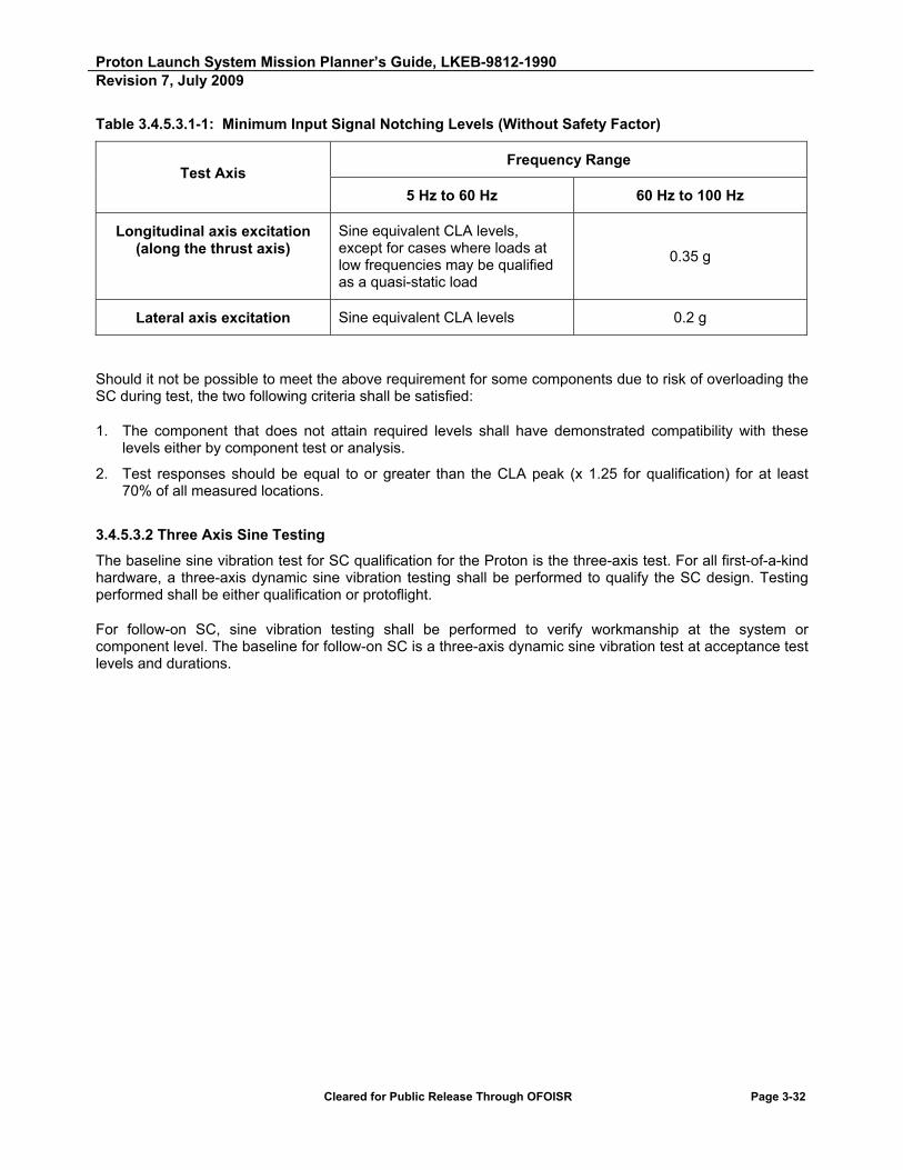
Proton Launch System Mission Planner’s Guide, LKEB-9812-1990 Revision 7, July 2009
Cleared for Public Release Through OFOISR Page 3-32
Table 3.4.5.3.1-1: Minimum Input Signal Notching Levels (Without Safety Factor)
Test Axis Frequency Range
5 Hz to 60 Hz 60 Hz to 100 Hz
Longitudinal axis excitation (along the thrust axis)
Sine equivalent CLA levels, except for cases where loads at low frequencies may be qualified as a quasi-static load
0.35 g
Lateral axis excitation Sine equivalent CLA levels 0.2 g
Should it not be possible to meet the above requirement for some components due to risk of overloading the SC during test, the two following criteria shall be satisfied:
1. The component that does not attain required levels shall have demonstrated compatibility with these levels either by component test or analysis.
2. Test responses should be equal to or greater than the CLA peak (x 1.25 for qualification) for at least 70% of all measured locations.
3.4.5.3.2 Three Axis Sine Testing
The baseline sine vibration test for SC qualification for the Proton is the three-axis test. For all first-of-a-kind hardware, a three-axis dynamic sine vibration testing shall be performed to qualify the SC design. Testing performed shall be either qualification or protoflight.
For follow-on SC, sine vibration testing shall be performed to verify workmanship at the system or component level. The baseline for follow-on SC is a three-axis dynamic sine vibration test at acceptance test levels and durations.
Proton Launch System Mission Planner’s Guide, LKEB-9812-1990 Revision 7, July 2009
Cleared for Public Release Through OFOISR Page 3-33
3.4.5.3.3 Single Axis Sine Testing
For a SC bus that has been three-axes tested previously, it is sometimes preferable for SC manufacturers to utilize a single axis sine vibration test. In lieu of a three-axis dynamic sine vibration test, a single axis test (thrust axis) may be used for acceptance testing if the SC manufacturer submits a waiver to ILS. This waiver must demonstrate that the SC meets certain criteria. The SC manufacturer shall request a waiver for a single axis test to ILS no less than three weeks before testing. This waiver shall include the following:
1. Verification of the SC Finite Element Model (FEM) by test. The FEM shall have been test-correlated during product line modal or sine testing. FEMs of secondary hardware not included in first-of-a-kind testing shall be verified at the component level. The SC manufacturer shall provide a matrix in the format provided in Section 3.4.6 that substantiates the SC FEM is validated based on test.
2. Demonstration of adequate coupling between the thrust and lateral axes. At least 70% of the peak lateral responses must be realized during the single axis testing to demonstrate adequate coupling between the thrust and lateral axes. This criterion must be verified by analysis based on a CLA simulation of single and three-axis testing. Components that are not exposed to acceptance levels shall be tested for workmanship at the component level. The SC manufacturer shall provide a matrix, as specified in Section 3.4.6, to verify that minimum peak lateral responses are realized.
3. Verification of new or changed hardware. System or component level testing shall verify any hardware not included in first-of-a-kind testing and not tested to protoflight levels during single axis testing. The SCC shall identify all hardware that is new or changed from previous three-axis testing. The new and changed hardware shall be tabulated and the method of verification documented according to the format specified in Section 3.4.6.
The SCC shall review the single axis test results and confirm that the analysis and test criteria provided have been met. If the test criteria are not met, the SCC may be required to revert to a three-axis sine vibration test or submit a waiver.
3.4.5.4 Random Vibration
The Proton random environment is based upon ground transportation loads, which the SC will be exposed to during transport from the payload processing facility to the launch site. This environment is defined as an equivalent random environment from a frequency range of 2 to 50 Hz. A fatigue analysis and/or some combination of a system level test and component level test may be used to demonstrate compatibility with this environment.

Proton Launch System Mission Planner’s Guide, LKEB-9812-1990 Revision 7, July 2009
Cleared for Public Release Through OFOISR Page 3-34
3.4.5.5 Shock Test Requirements
A shock test using the adapter clamp system with the flight adapter and SC is required at the SCC’s facility in conjunction with a mechanical/electrical fitcheck for first-of-a-kind SC and the first follow-on SC in a series. For this test, the flight band will be tensioned, as per the manufacturer’s separation system test procedure. Shock levels will be measured at a location 30 to 120 mm above the SC separation plane by the SCC in a minimum of two locations: 1) in proximity to the clampband firing device, and 2) approximately 90 from this location. SC measurements shall be provided to ILS by the SCC following the test to validate conformance with the shock level specification provided in this PMPG.
For subsequent SC, a shock test is not required, providing that there are no significant differences in the SC equipment configuration in proximity to the separation clampband interface.
3.4.6 SC Environmental Test Plan and Report
A SC environmental test plan will be provided to ILS prior to the start of the test program. This test plan will outline the test philosophy as it applies to both new and previously qualified SC hardware. The test plan shall include the following: rationale for acceptance versus protoflight test approach, identification of component versus system level tests, test level durations and acceptable test tolerances.
An environmental test report shall be provided to ILS no later than one month following the completion of the SC environmental test program. This report summarizes the static, sine vibration, acoustics, random vibration and shock testing performed and documents the adequacy of the SC for the Proton environmental loads. This report shall include for each environment: 1) a description of the test setup, 2) as-tested input levels and test durations and 3) a description of any anomalies that may have occurred during the test. Input test levels shall be compared to the environmental levels defined in Section 3.4. For the sine test, test levels shall also be compared to the final CLA results.
Table 3.4.6-1 provides an example of the report format required to verify that coupled loads results have been enveloped by the combination of sine, static and component level testing. Notching inputs should also be summarized as shown in Table 3.4.6-2. The test report shall also include a comparison of the SC FEM predictions and test responses, as shown in the example in Table 3.4.6-3. Frequency response comparisons should also be provided for primary SC modes and major subsystem assemblies (i.e., antenna feeds/reflectors, solar arrays, bus panels).

Proton Launch System Mission Planner’s Guide, LKEB-9812-1990 Revision 7, July 2009
Cleared for Public Release Through OFOILV Page 3-35
Table 3.4.6-1: Typical Format For Post-Test Report And CLA Summary Matrix
NASTRAN Grid ID
Accel No/Axis
Des
crip
tio
n o
f A
ccel
ero
met
er
Max Predicted CLA (g)
Allowable Design (g)
X-Axis Test Y-Axis Test Z-Axis Test
Ove
rall
Max
R
esp
on
se (
g)
Des
ign
Allo
w/
Max
Res
po
nse
Max
R
esp
on
se/C
LA
CLA Value Covered By
Unit Qual Level
(g)
Unit Qual Freq (Hz)
Max
R
esp
on
se (
g)
Max
R
esp
on
se
Fre
q (
Hz)
Max
R
esp
on
se (
g)
Max
R
esp
on
se
Fre
q (
Hz)
Max
R
esp
on
se (
g)
Max
R
esp
on
se
Fre
q (
Hz)
Sine Test
Static Test
Unit Test Design
10001 100-X N Solar Array
18 30 25 38 10 42 4 42 25 1.20 1.39 1 25 5-100
10002 101-Y N Solar Array
17 25 5 38 16 38 5 38 16 1.56 0.94 1 20 5-100
10003 102-Z N Solar Array
6 10 3 42 3 42 3.5 42 3.5 2.86 0.58 1 10 5-100
10004 103-X S Solar Array
18 30 25 38 11 42 4 42 25 1.20 1.39 1 25 5-100
10005 104-Y S Solar Array
17 25 5 38 16 38 5 38 16 1.56 0.94 1 20 5-100
10006 105-Z S Solar Array
6 10 3 42 3 42 3.5 42 3.5 2.86 0.58 1 10 5-100
Total 2 2 2 0
% 0.33 0.33 0.33 0.00

Proton Launch System Mission Planner’s Guide, LKEB-9812-1990 Revision 7, July 2009
Cleared for Public Release Through OFOISR Page 3-36
Table 3.4.6-2: Typical Post-Test Report Sine Vibration Notching Summary
X-Axis Test Notch Y-Axis Test Notch Z-Axis Test Notch
Freq (Hz)
Accel No.
Description/Comp Peak (g)
Freq (Hz)
Accel No.
Description/ Comp
Peak (g)
Freq (Hz)
Accel No.
Description/Comp
Peak (g)
12-14 201-X Base Bending Input 0.2 12-14 301-Y Base Bending Input
0.2 37-39 501-Z Tank Strut 5.5
36-40 100-X Solar Array 25 35-39 75-Y East Reflector 17
Table 3.4.6-3: Typical Summary Verification of SC FEM Based on Sine Vibration Test
System Description
System Mode Description
Test Freq (Hz)
Analysis Freq (Hz)
Ratio Test to Analysis
Test Reference New
Hardware
Primary Structure 1st Bending-X/Y 14.10 14.30 0.99 System level sine testing
no
Primary Structure 2nd Bending-X/Y 25.70 25.90 0.99 System level sine testing
no
Primary Structure 1st Axial 40.00 42.00 0.95 System level sine testing
no
Subsystem Antenna Feed 42.70 44.10 0.97 Component yes
Component Reaction Wheel 38.00 40.00 0.95 System level sine testing
no
Component SADM 39.00 37.00 1.05 System level sine testing
no
Subsystem Reflectors 38.50 38.00 1.01 System level sine testing
no
Subsystem Solar Arrays 40.10 44.10 0.91 System level sine testing
no
Component Batteries 42.80 40.10 1.07 Component yes

Proton Launch System Mission Planner’s Guide, LKEB-9812-1990 Revision 7, July 2009
Cleared for Public Release Through OFOISR Page 3-37
3.5 ELECTROMAGNETIC COMPATIBILITY (EMC)
Electromagnetic Interference (EMI) emissions and susceptibility of the SC and the LV shall be tested separately (individually) to the extent necessary to ensure EMC of the fully integrated system.
3.5.1 EMI Safety Factor (EMISF) and Reserve Margin (EMIRM)
The integrated SC/LV system shall be designed to provide EMC with a minimum of 20 dB EMIRM (versus dc no-fire threshold) for ordnance circuits, and 6 dB EMIRM for the entire system.
3.5.2 Radiated Emissions
The LV intentional emissions are described in Table 3.5.2-1. The SC needs to be compatible with these emissions.
The LV generated and launch base spurious EMI sources shall not exceed the levels of Figure 3.5.2-1 in a plane 1 meter below and parallel to the SC/LV interface plane.
3.5.3 Radiated Susceptibility
LV and launch pad susceptibility limits for Proton M/Breeze M are provided in Figure 3.5.3-1. The antenna locations for the Breeze M are shown in Figure 3.5.3-2.
The LV/Breeze M susceptibility limits have been defined at 1 meter from the SC outer surface for the adapter/SC interface plane.
SC-generated and spurious EMI sources should not exceed the levels of Figure 3.5.3-1 in a plane 1 meter below and parallel to the SC/LV interface plane. Intentional radiation above these values must be verified by an EMC analysis performed by ILS (see Section 3.5.4).
3.5.4 EMC of RF Transmitters and Receivers
The RF characteristics of all SC transmitters and receivers shall be provided by the Customer according to the data requirements of Appendix C. ILS will perform an EMC analysis for each mission to verify the compatibility of SC, LV and launch pad transmitters and receivers.

Proton Launch System Mission Planner’s Guide, LKEB-9812-1990 Revision 7, July 2009
Cleared for Public Release Through OFOISR Page 3-38
Table 3.5.2-1: Proton M/Breeze M RF Equipment Characteristics
Description
Transmitters Receivers
TLM Stage 1
TLM Stage 1
TLM Stage 2
TLM Stage 3
TLM Breeze M
TrajectoryControl
Glonass/ GPS
TrajectoryControl
1. Carrier frequency (MHz)
200.74; 203.3
247.3 - 249.86
239.3 1010.5; 1013.06
1018.5; 1020.5
3410 1570 - 1640
5754.9
2. 3 dB bandwidth (MHz)
0.6 0.6 0.6 0.6 0.563 0.340
0.066 50 40
3. Modulation type and characteristics
APM-FM APM-FM APM-FM APM-FM PCM-FM PCM/PhM/PSK
PCM/NPSK/PhM
PCM/PhM/PSK
4. Transmitter output power at carrier frequency (dBW)
12.3 12.3 12.3 12.3 9.5 6
5. Receiver sensitivity at carrier frequency (dBW)
-160 -133
6. Antenna gain coefficient (dB)
-10 -10 -10 -10 3 dB (0), -10 dB (75)
2.3 dB (0), -10 dB (70)
3 0 dB (0), -12 dB (70)
7. Antenna type, polarization
Omni, linear Semi-directional,
linear
Semi-directional,
circular
Semi-directional,
circular
Semi-directional,
circular
8. Operating on launch pad?
Yes Yes Yes Yes Yes No Yes No
9. Operating in flight?
Yes Yes Yes Yes Yes Yes Yes Yes
APM/FM - Amplitude Pulse Modulation/Frequency Modulation PCM/FM - Pulse Code Modulation/Frequency Modulation PM - Pulse Modulation PCM/PhM/PSK - Pulse Code Modulation/Phase Modulation/Phase Shift Keying PCM/NPSK/PhM - Pulse Code Modulation/Noise-Like Phase Shift Keying/Phase Modulation

Proton Launch System Mission Planner’s Guide, LKEB-9812-1990 Revision 7, July 2009
Cleared for Public Release Through OFOISR Page 3-39
Figure 3.5.2-1: Electric Field Intensity Levels Generated by Proton M/Breeze M Launch Equipment
0
20
40
60
80
100
120
140
100 1000 10000 100000
Fie
ld In
ten
sity
(dB
·μV
/m)
Frequency (MHz)
239 to 240 MHz125 dB·μV/m
247 to 250 MHz113 dB·μV/m
1010.5 to 1020.5 MHz125 dB·μV/m
1570 to 1640 MHz46 dB·μV/m
5750 to 5760 MHz30 dB·μV/m
3410 MHz113 dB·μV/m
200 to 210 MHz113 dB·μV/m
Frequency (MHz) Field Intensity (dB·μV/m) Bandwidth at 3 dB·μV/m
200 to 210 113 0.6239 to 240 125 0.6247 to 250 113 0.6
1010 to 1013 125 0.61018 to 1020 125 0.341570 to 1640 46 50
3410 113 0.0665750 to 5760 30 40
100000 8 N/A

Proton Launch System Mission Planner’s Guide, LKEB-9812-1990 Revision 7, July 2009
Cleared for Public Release Through OFOISR Page 3-40
Figure 3.5.3-1: Proton M/Breeze M and Launch Pad Radiated Susceptibility
0
20
40
60
80
100
120
140
160
180
100 1000 10000 100000
Fie
ld In
ten
sity
(dB∙u
V/m
)
Frequency (MHz)
1570 - 1640 MHz60 dB∙μV/m
134 dB∙μV/m
5750 - 5760 MHz60 dB∙μV/m
Frequency (MHz)
Field Intensity (dB∙μV/m)
100 to 1570 1341570 to 1640 451640 to 5700 1345700 to 5800 30
5800 to 20000 134

Proton Launch System Mission Planner’s Guide, LKEB-9812-1990 Revision 7, July 2009
Cleared for Public Release Through OFOILV Page 3-41
Figure 3.5.3-2: Breeze M Antennae Locations

Intentionally Blank

Proton Launch System Mission Planner’s Guide
SECTION 4
Spacecraft Interfaces


Proton Launch System Mission Planner’s Guide, LKEB-9812-1990 Revision 7, July 2009
Cleared for Public Release Through OFOISR Page 4-1
4. SPACECRAFT INTERFACES
4.1 MECHANICAL INTERFACES
4.1.1 Structural Interfaces
The Spacecraft (SC)-to-Launch Vehicle (LV) structural/mechanical interfaces include a Payload Adapter (PLA) interface ring, a separation system, umbilical connectors, separation switches and bonding straps (if needed). The structural/mechanical interfaces are defined for each Adapter System (AS) in Appendix D of this Proton Mission Planner’s Guide.
The LV coordinate system is shown in Figure 4.1.1-1 with a representative SC and its coordinate system.
Figure 4.1.1-1: LV and Typical SC Coordinate System
Notes:
a) SC longitudinal axis is in direction of flight.
b) Two remaining SC axes are in SC separation plane.
c) Proton M (+XLV) is longitudinal in direction of flight.
d) Proton M (+YLV) is in direction of gravity vector during horizontal transportation operations.
4.1.2 General SC Structural and Load Requirements
4.1.2.1 Design Criteria
The SC and LV interface structure shall support the SC during the limit load condition without yielding. The clearance between the flanges of the SC and the adapter prior to clampband tensioning shall not exceed 0.6 mm. The geometry of the SC flange is provided in Appendix D for a temperature of 21°C. The surface flatness of the SC interface ring shall be less than 0.3 mm. The coating of the surface of the SC/LV interface structural elements shall be conductive.
Proton Launch System Mission Planner’s Guide, LKEB-9812-1990 Revision 7, July 2009
Cleared for Public Release Through OFOISR Page 4-2
4.1.2.2 SC Stiffness
The SC primary structural stiffness shall be such that the minimum fundamental lateral and axial mode frequencies shall be greater than 8.5 Hz and 25 Hz, respectively, as cantilevered from a rigid interface. The SC/LV interface is assumed to behave linearly under all loading conditions.
4.1.2.3 SC Interface Loads
The SC lifting device and structure shall be capable of lifting the SC plus the PLA and the separation system. Maximum adapter, separation system and other mass to be lifted by the SC 220 kg.
Loads affecting the SC at the SC/LV interface include the adapter system springs and the SC/LV electrical umbilical connectors. The adapter system spring forces and the SC/LV electrical umbilical connector forces are provided in Appendix D of this PMPG.
4.1.2.4 SC Mass and Center of Gravity (CG) Offset Requirements
The allowable position of the SC Center of Gravity (CG) relative to the SC/AS separation plane in the longitudinal axis is determined for each type of AS and separation system and are presented in Appendix D.
The SC CG displacement from the LV longitudinal X axis shall not exceed 20 mm in any lateral direction.
4.1.3 Payload Fairing (PLF) Interfaces
This section provides a description of the PLF interfaces, including generic fairing useable volume, allowable access door locations and RF window locations.

Proton Launch System Mission Planner’s Guide, LKEB-9812-1990 Revision 7, July 2009
Cleared for Public Release Through OFOISR Page 4-3
4.1.3.1 PLF General Description
For commercial launches with the Breeze M, two PLF lengths are available: 13305 mm (Figure 4.1.3.1-1a and Figure 4.1.3.1-1b) and 15255 mm (Figure 4.1.3.1-2a and Figure 4.1.3.1-2b). The 15255 mm fairing (PLF-BR-15255), which is the standard, and the 13305 mm fairing (PLF-BR-13305) are of similar design.
Specific useable volumes (i.e., volume under PLF useable for SC accommodation) for the two fairing types tailored to individual adapter systems are provided in Appendix E. Specific adapters take into account required adapter clearances for installation and required flight clearances with the adapter structure.
4.1.3.2 PLF Access Door Locations
The bottom part of the PLF accommodates a door for access to the clampband tension-monitoring electrical connectors and may also accommodate doors for access to the SC, in the locations for the two PLF versions shown in Figures 4.1.3.1-1a and 4.1.3.1-1b, 4.1.3.1-2a and 4.1.3.1-2b, respectively. Some mission-unique designs for door locations may be possible in coordination with KhSC. The Customer may use these doors for access to SC-related interface equipment. These access requirements need to be coordinated and agreed upon with ILS in the mission-specific ICD. From the time of fairing encapsulation up to the beginning of LV fueling on the launch pad, coordination with ILS is necessary for scheduling access through these doors.
4.1.3.3 RF Window Locations
Figures 4.1.3.1-1a, 4.1.3.1-1b, 4.1.3.1-2a and 4.1.3.1-2b show the locations of access doors and RF window cutouts for the two PLF versions, respectively.
There are two RF window positions in the PLF to take into account the possible view angles required at each of the two Proton launch pads. When the launch pad is designated, one out of the two windows will be replaced with a RF-opaque cover, leaving one active window for transmission of the SC telemetry and command signal between the SC and Control Room 4102 via the Bunker.

Proton Launch System Mission Planner’s Guide, LKEB-9812-1990 Revision 7, July 2009
Cleared for Public Release Through OFOISR Page 4-4
Figure 4.1.3.1-1a: Proton Breeze M PLF-BR-13305 Commercial Fairing General Layout (Sheet 1 of 2)

Proton Launch System Mission Planner’s Guide, LKEB-9812-1990 Revision 7, July 2009
Cleared for Public Release Through OFOISR Page 4-5
Figure 4.1.3.1-1b: Proton Breeze M PLF-BR-13305 Commercial Fairing General Layout (Sheet 2 of 2)

Proton Launch System Mission Planner’s Guide, LKEB-9812-1990 Revision 7, July 2009
Cleared for Public Release Through OFOISR Page 4-6
Figure 4.1.3.1-2a: Proton Breeze M PLF-BR-15255 Commercial Fairing General Layout (Sheet 1 of 2)
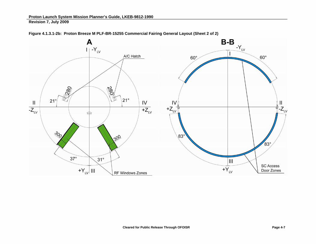
Proton Launch System Mission Planner’s Guide, LKEB-9812-1990 Revision 7, July 2009
Cleared for Public Release Through OFOISR Page 4-7
Figure 4.1.3.1-2b: Proton Breeze M PLF-BR-15255 Commercial Fairing General Layout (Sheet 2 of 2)

Proton Launch System Mission Planner’s Guide, LKEB-9812-1990 Revision 7, July 2009
Cleared for Public Release Through OFOISR Page 4-8
4.1.4 Adapters
The adapter system links the Breeze M and the SC mechanically and electrically during all phases of combined operation prior to the separation of the SC and Breeze M during flight.
Table 4.1.4-1 lists the available PLA systems used by the Proton LV.
A general view of available adapter systems is shown in Figure 4.1.4-1. A description and drawings of the mechanical interface of available adapter systems are shown in the corresponding sections of Appendix D. Other adapter systems may be developed that include other separation systems, in accordance with the requirements of the SC developer.
Figure 4.1.4-1: Available Adapter Systems
Table 4.1.4-1: Available Proton Adapter Systems
Adapter System Height (mm)
Mass (kg)
Adapter System Characteristics Appendix Reference
937VB-1168 1168 120 15 degree ramp angle on the SC side, 9 degree ramp angle on the AS side, 30 kN band tension
D.1
1194VX-1000 1000 110 15 degrees ramp angle on SC side, 9 degrees ramp angle on adapter side, 35 kN to 40 kN band tension
D.2
1194VS-1000 1000 110 15 degree ramp angle on SC side, 9 degrees ramp angle on adapter side, 54 kN band tension
D.2
1666V-1000 1000 155 15 degree ramp angle on the SC side, 11 degree ramp angle on the AS side, 30 kN band tension
D.3
1664HP-1000 1000 120 4 hard-point separation system D.4
Proton Launch System Mission Planner’s Guide, LKEB-9812-1990 Revision 7, July 2009
Cleared for Public Release Through OFOISR Page 4-9
4.1.5 Payload/Adapter Separation Systems
Currently, annular and hard-point separation systems may be used for separation of the SC from the AS.
Annular separation systems of the following reference diameters may be used: 937 mm, 1194 mm, and 1666 mm. If required, a 2624 mm interface may be used. A specific separation system is proposed in each specific case, depending on SC requirements. The separation system can be based on either the traditional pair of pyrotechnically-initiated bolt cutters or a low-shock ClampBand Opening Device (CBOD). The RUAG CBOD system has been flight demonstrated on several launch vehicles, but not yet on Proton. The ground test qualification for use of RUAG CBOD on Proton has been completed. First flight demonstration on Proton is expected in 2010. KhSC is in the process of ground qualification for use on Proton of a CBOD system manufactured by CASA.
A hard-point attachment separation system may be used if the properties and configuration of the SC allow mechanical latches to be installed on the adapter with a pyro actuator or pyro latches (nominal 1664 mm interface). When necessary, a different hard-point interface required by the Customer may be used.
Separation systems have the following typical makeup:
A separation assembly (see Table 4.1.5-1); a set of push-type actuators
Umbilical electrical connectors
Separation verification sensors
A pneumatic purge fitting (if required)
Alternative separation systems of the annual and hard-point type are shown in Table 4.1.5-1.

Proton Launch System Mission Planner’s Guide, LKEB-9812-1990 Revision 7, July 2009
Cleared for Public Release Through OFOISR Page 4-10
Table 4.1.5-1: Mechanical Interface Options for Separation System
# Interface Diameters
(mm) Separation System
Designation Separation System
Manufacturers Separation System
Types
1 937 937VB RUAG AEROSPACE SWEDEN AB/KhSC
Annular
2 937VS RUAG AEROSPACE SWEDEN AB/KhSC
Annular
3 937LPSU EADS CASA Espacio/KhSC
Annular
4 1194 1194VX RUAG AEROSPACE SWEDEN AB/KhSC
Annular
5 1194VS RUAG AEROSPACE SWEDEN AB/KhSC
Annular
6 1194LPSU EADS CASA Espacio/KhSC
Annular
7 1666 1666V RUAG AEROSPACE SWEDEN AB/KhSC
Annular
8 1666LPSU EADS CASA Espacio/KHSC
Annular
9 1666S RUAG AEROSPACE SWEDEN AB/KhSC
Annular
10 1664 1664HP KhSC Point attachment
Requirements are levied on the energy of separation system push-type actuators in order to satisfy the Customer's SC separation requirements. A typical example of push spring characteristics is shown in Table 4.1.5-2. The characteristics may be varied based on the requirements of a specific SC. If SC spin is required, push-type actuators with different travel distances may be installed.
Table 4.1.5-2: Push Spring Characteristics
Travel (mm)
Initial Force (N)
Final Force (N)
Nominal Energy of One Push Spring (J)
Nominal Energy of All Push Springs (J)
65 1180.0 100.0 41.0 328.0

Proton Launch System Mission Planner’s Guide, LKEB-9812-1990 Revision 7, July 2009
Cleared for Public Release Through OFOISR Page 4-11
4.1.6 GN2/Dry Air Purge Option
Pursuant to particular contractual arrangements, the Customer can obtain a Gaseous Nitrogen (GN2)/dry air purge of the SC after PLF encapsulation via special pneumatic fittings at the adapter interface. GN2 can be provided via Customer-provided gas bottles during operations in the Payload Processing Facility (PPF), Building 92A-50, and on the launch pad up to MST rollback. At this time, the line can be connected to a dry air source running through the LV to provide a dry air purge up to lift-off. Characteristics of this purge system are as follows:
Item Characteristic
Number of fittings 1
Type fitting Pneumatic 0.172 inch (4.36 mm) internal diameter, 0.281 inch (7.14 mm) external diameter, 303 CRES material (provided by Customer)
Period of operation a) Accessible by Customer during payload operations in PPF and on-pad, prior to MST rollback (including during transportation operations, as mutually agreed upon between ILS and Customer)
b) Connected to ILS/KhSC dry air source through LV from MST rollback to launch
Operational gas Gaseous nitrogen (GN2) or air
Particulate size <50 microns
Hydrocarbon content Maximum condensable hydrocarbons -
5.0 X 10⁻⁴% by mass
Helium content At standard atmosphere concentrations -
5.0 X 10⁻⁴% maximum by volume
Filtration Preliminary purification and availability of filter at system outlet with mesh of 25 microns to 50 microns
Temperature -30C to +30C
Humidity requirement Maximum dew point temperature = -55C
Flow rate at SC/LV interface 450 cm3/min to 650 cm3/min
Maximum pressure drop from SC/LV interface through SC
0.048 Pa
For a typical mechanical interface layout, see Appendix D of this Proton Mission Planner’s Guide.

Proton Launch System Mission Planner’s Guide, LKEB-9812-1990 Revision 7, July 2009
Cleared for Public Release Through OFOISR Page 4-12
4.2 ELECTRICAL INTERFACES
Electrical interfaces include the SC/LV airborne interfaces, Electrical Ground Support Equipment (EGSE) interfaces, and telemetry/command links.
4.2.1 Airborne Interfaces
Electrical umbilical interfaces are used primarily for providing power to the SC from Customer ground power supplies located in the Vault under the launch pad. They are also used for hardline telemetry and command links between the SC and the Customer GSE located in the PPF Control Room 4102 or the launch control Bunker at the pad. Additionally, the Customer has an option to have SC telemetry recorded by the Breeze M telemetry system via these umbilicals.
4.2.1.1 Electrical Connectors
Two 37-pin or 61-pin umbilical connectors are provided at the SC interface with the LV adapter. The connectors are spring-loaded and at separation will disconnect from the adapter. The type of umbilical connector is mutually agreed to between ILS and the Customer.
Appendix D describes the standard adapters and also provides the type, location and mechanical configuration for these connectors.
4.2.1.2 Separation Verification
Two diametrically opposed separation microswitches are provided on the top adapter interface flange. Refer to Appendix D for specific locations and mounting configuration for each specific adapter. At separation, the microswitches will open a circuit and the LV telemetry will detect this as the separation event.
In addition, continuity loops are provided in each umbilical connector on the SC side. At separation, the umbilical connectors will disengage, thereby opening these circuits and providing a redundant indication of separation to the LV telemetry system.
4.2.1.3 Interface Electrical Constraints
All SC and LV electrical interface circuits shall be restricted at least 20 seconds prior to SC separation, such that there is no current flow greater than 100 milliampere per wire during the separation event.
Proton Launch System Mission Planner’s Guide, LKEB-9812-1990 Revision 7, July 2009
Cleared for Public Release Through OFOISR Page 4-13
4.2.1.4 Spacecraft Environment Telemetry
Flight events and mechanical and temperature environments during SC orbital insertion are recorded by the Proton M LV third stage and Breeze M telemetry systems with the aid of sensor equipment mounted on the adapter system and fairing.
AS sensors are mounted near the upper flange and record the following:
High-frequency vibrations in the direction of flight and in the radial direction
Longitudinal and lateral accelerations
The AS acoustic environment
Temperature values in the upper part of the AS
Sensors on the fairing prior to its separation measure:
Acoustic pressure inside and outside the fairing during first 100 seconds of flight
Internal static pressures
Fairing temperature values
Mechanical and temperature environments are measured during LV operation, including high-frequency vibration parameters and acoustic pressure, low-frequency vibration parameters, and AS temperatures, as well as the fairing acoustic pressure and temperature.
After separation from the LV, the Breeze M telemetry system measures AS temperature parameters and records SC separation events. In special cases, it may also measure low-frequency AS vibrations.
Breeze M telemetry system transmission capabilities and data transfer rates are determined by radio coverage conditions, and implement the following modes:
Direct data transmission with simultaneous recording
Data recording
Direct transmission with simultaneous playback of previously recorded data
Direct transmission of data with redundancy in a time delay mode
Five accelerometers are mounted near the top of the adapter interface flange to record acceleration from lift-off until stage three/four separation. Three accelerometers measure longitudinal loads and two measure lateral loads. Refer to Section 4.2.1.6 for characteristics of these telemetry channels.

Proton Launch System Mission Planner’s Guide, LKEB-9812-1990 Revision 7, July 2009
Cleared for Public Release Through OFOISR Page 4-14
4.2.1.5 Pre-Separation “Dry Loop” Commands
The Customer may choose as an optional service up to two primary and two redundant in-flight commands in the form of relay closures for initiating SC commands during flight. The command for closure will be issued after launch and before SC/LV separation. Timing and signal characteristic requirements need to be provided by the Customer no later than at L-12 months. Characteristics of this command are as follows:
Table 4.2.1.5-1: Relay Closure Command Characteristics
Item Characteristic
Type of relay Electronic switches on IRF7103 transistors
Actuation time Any time from launch to SC separation
Pulse duration 0.1 second to 10 minutes
Timing accuracy 32 ms
Allowable maximum voltage through relay contact at relay closure 16 Volts
Allowable maximum steady-state current through SC/LV interface contact 1 Ampere
4.2.1.6 LV Telemetry, Command and Power
The LV provides the SC separation command and the power for initiating the separation system. There is no LV power or command lines which pass across the SC separation plane.
Table 4.2.1.6-1 provides a description of the measurement system that is used during ground handling. Table 4.2.1.6-2 provides the characteristics and location of each flight telemetry sensor registering flight events of an example mission. Finally, Figures 4.2.1.6-1 through 4.2.1.6-5 show the locations of each sensor on the LV or ground transportation device.
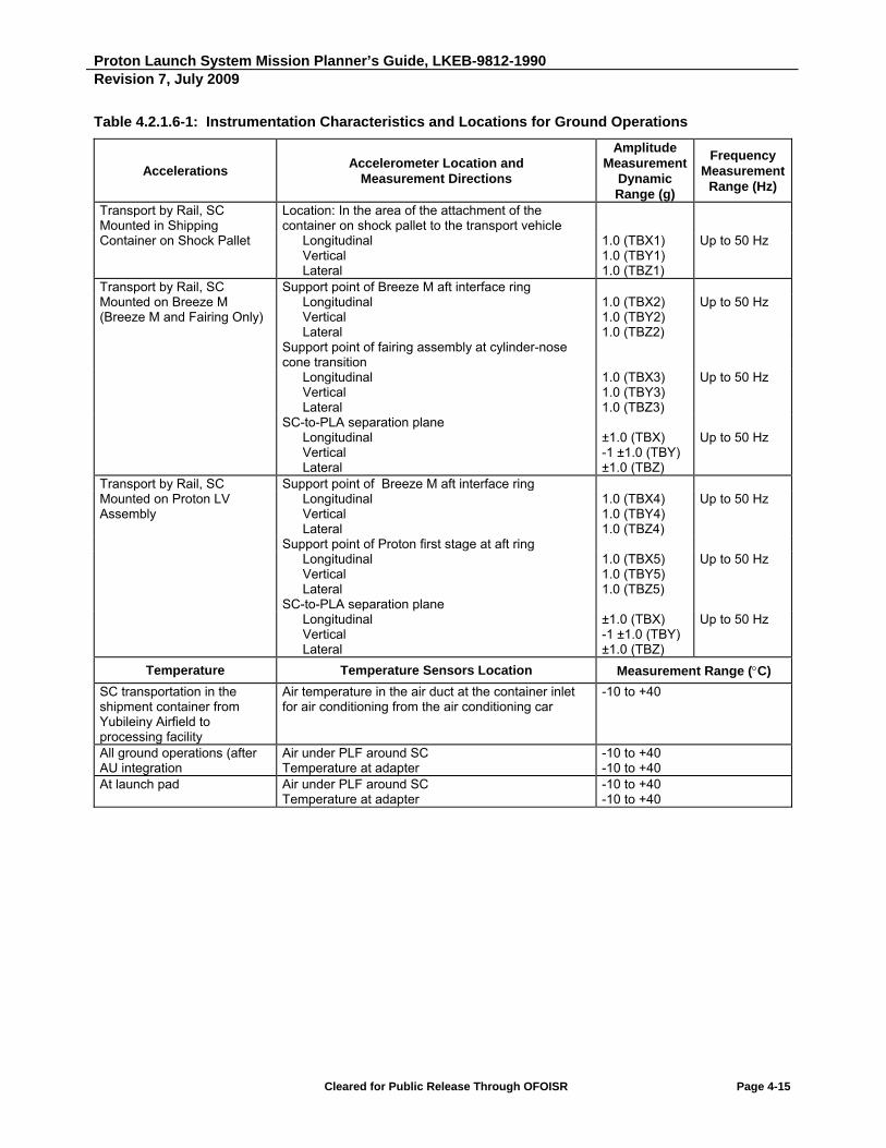
Proton Launch System Mission Planner’s Guide, LKEB-9812-1990 Revision 7, July 2009
Cleared for Public Release Through OFOISR Page 4-15
Table 4.2.1.6-1: Instrumentation Characteristics and Locations for Ground Operations
Accelerations Accelerometer Location and
Measurement Directions
Amplitude Measurement
Dynamic Range (g)
Frequency Measurement
Range (Hz)
Transport by Rail, SC Mounted in Shipping Container on Shock Pallet
Location: In the area of the attachment of the container on shock pallet to the transport vehicle
Longitudinal Vertical Lateral
1.0 (TBX1) 1.0 (TBY1) 1.0 (TBZ1)
Up to 50 Hz
Transport by Rail, SC Mounted on Breeze M (Breeze M and Fairing Only)
Support point of Breeze M aft interface ring Longitudinal Vertical Lateral
1.0 (TBX2) 1.0 (TBY2) 1.0 (TBZ2)
Up to 50 Hz
Support point of fairing assembly at cylinder-nose cone transition
Longitudinal Vertical Lateral
1.0 (TBX3) 1.0 (TBY3) 1.0 (TBZ3)
Up to 50 Hz
SC-to-PLA separation plane Longitudinal Vertical Lateral
±1.0 (TBX) -1 ±1.0 (TBY) ±1.0 (TBZ)
Up to 50 Hz
Transport by Rail, SC Mounted on Proton LV Assembly
Support point of Breeze M aft interface ring Longitudinal Vertical Lateral
1.0 (TBX4) 1.0 (TBY4) 1.0 (TBZ4)
Up to 50 Hz
Support point of Proton first stage at aft ring Longitudinal Vertical Lateral
1.0 (TBX5) 1.0 (TBY5) 1.0 (TBZ5)
Up to 50 Hz
SC-to-PLA separation plane Longitudinal Vertical Lateral
±1.0 (TBX) -1 ±1.0 (TBY) ±1.0 (TBZ)
Up to 50 Hz
Temperature Temperature Sensors Location Measurement Range (C)
SC transportation in the shipment container from Yubileiny Airfield to processing facility
Air temperature in the air duct at the container inlet for air conditioning from the air conditioning car
-10 to +40
All ground operations (after AU integration
Air under PLF around SC Temperature at adapter
-10 to +40 -10 to +40
At launch pad Air under PLF around SC Temperature at adapter
-10 to +40 -10 to +40

Proton Launch System Mission Planner’s Guide, LKEB-9812-1990 Revision 7, July 2009
Cleared for Public Release Through OFOISR Page 4-16
Table 4.2.1.6-1: Instrumentation Characteristics and Locations for Ground Operations (Continued)
Humidity Humidity Sensors Location Measurement Range
Transportation in Container Relative humidity inside shipping container 0 - 90% All Transportation Events Relative humidity of inlet, exit air from KhSC thermal
conditioning car 0 - 80%
Contamination Contamination Sensors Location Measurement Range
All Ground Events Particulate size at inlet/exit from air conditioning car 0.5 microns/5 microns and higher
All Ground Events Witness plates (2) located inside PLF On-Pad Access to PLF air supply for manual reading of
contamination levels 0.5 microns/5 microns and higher
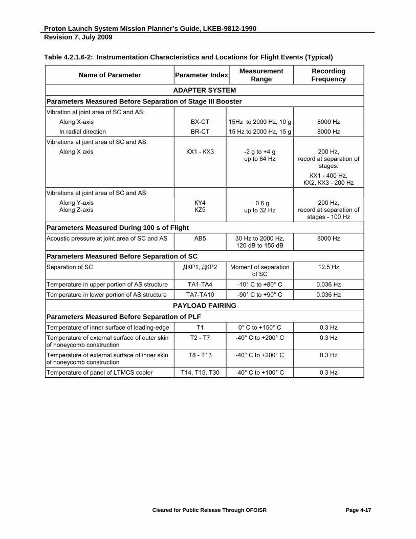
Proton Launch System Mission Planner’s Guide, LKEB-9812-1990 Revision 7, July 2009
Cleared for Public Release Through OFOISR Page 4-17
Table 4.2.1.6-2: Instrumentation Characteristics and Locations for Flight Events (Typical)
Name of Parameter Parameter IndexMeasurement
Range Recording Frequency
ADAPTER SYSTEM
Parameters Measured Before Separation of Stage III Booster
Vibration at joint area of SC and AS:
Along Х-axis ВХ-СТ 15Hz to 2000 Hz, 10 g 8000 Hz
In radial direction ВR-CТ 15 Hz to 2000 Hz, 15 g 8000 Hz
Vibrations at joint area of SC and AS:
Along Х axis
КХ1 - КХ3
-2 g to +4 g up to 64 Hz
200 Hz, record at separation of
stages:
КХ1 - 400 Hz, КХ2, КХ3 - 200 Hz
Vibrations at joint area of SC and AS
Along Y-axis Along Z-axis
КY4 КZ5
0.6 g up to 32 Hz
200 Hz, record at separation of
stages - 100 Hz
Parameters Measured During 100 s of Flight
Acoustic pressure at joint area of SC and AS АВ5 30 Hz to 2000 Hz, 120 dB to 155 dB
8000 Hz
Parameters Measured Before Separation of SC
Separation of SC ДКР1, ДКР2 Moment of separation of SC
12.5 Hz
Temperature in upper portion of AS structure ТА1-ТА4 -10° С to +80° С 0.036 Hz
Temperature in lower portion of AS structure ТА7-ТА10 -90° С to +90° С 0.036 Hz
PAYLOAD FAIRING
Parameters Measured Before Separation of PLF
Temperature of inner surface of leading-edge Т1 0° С to +150° С 0.3 Hz
Temperature of external surface of outer skin of honeycomb construction
Т2 - Т7 -40° С to +200° С 0.3 Hz
Temperature of external surface of inner skin of honeycomb construction
Т8 - Т13 -40° С to +200° С 0.3 Hz
Temperature of panel of LTMCS cooler Т14, Т15, Т30 -40° С to +100° С 0.3 Hz
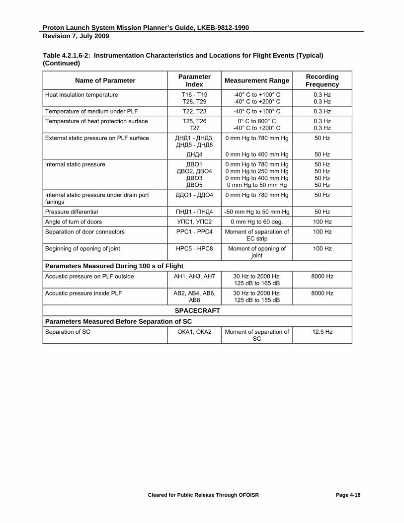
Proton Launch System Mission Planner’s Guide, LKEB-9812-1990 Revision 7, July 2009
Cleared for Public Release Through OFOISR Page 4-18
Table 4.2.1.6-2: Instrumentation Characteristics and Locations for Flight Events (Typical) (Continued)
Name of Parameter Parameter
Index Measurement Range
Recording Frequency
Heat insulation temperature Т16 - Т19 Т28, Т29
-40° С to +100° С -40° С to +200° С
0.3 Hz 0.3 Hz
Temperature of medium under PLF Т22, Т23 -40° С to +100° С 0.3 Hz
Temperature of heat protection surface Т25, Т26 Т27
0° С to 600° С -40° С to +200° С
0.3 Hz 0.3 Hz
External static pressure on PLF surface ДНД1 - ДНД3, ДНД5 - ДНД8
ДНД4
0 mm Hg to 780 mm Hg
0 mm Hg to 400 mm Hg
50 Hz
50 Hz
Internal static pressure ДВО1 ДВО2, ДВО4
ДВО3 ДВО5
0 mm Hg to 780 mm Hg 0 mm Hg to 250 mm Hg 0 mm Hg to 400 mm Hg 0 mm Hg to 50 mm Hg
50 Hz 50 Hz 50 Hz 50 Hz
Internal static pressure under drain port fairings
ДДО1 - ДДО4 0 mm Hg to 780 mm Hg 50 Hz
Pressure differential ПНД1 - ПНД4 -50 mm Hg to 50 mm Hg 50 Hz
Angle of turn of doors УПС1, УПС2 0 mm Hg to 60 deg. 100 Hz
Separation of door connectors РРС1 - РРС4 Moment of separation of EC strip
100 Hz
Beginning of opening of joint НРС5 - НРС8 Moment of opening of joint
100 Hz
Parameters Measured During 100 s of Flight
Acoustic pressure on PLF outside АН1, АН3, AH7 30 Hz to 2000 Hz, 125 dB to 165 dB
8000 Hz
Acoustic pressure inside PLF АВ2, АВ4, AB6, AB8
30 Hz to 2000 Hz, 125 dB to 155 dB
8000 Hz
SPACECRAFT
Parameters Measured Before Separation of SC
Separation of SC ОКА1, ОКА2 Moment of separation of SC
12.5 Hz

Proton Launch System Mission Planner’s Guide, LKEB-9812-1990 Revision 7, July 2009
Cleared for Public Release Through OFOISR Page 4-19
Figure 4.2.1.6-1: Instrumentation During Transportation of SC in Contractor’s Container
Rail transportation of SC in SC contractor’s container from Yubileiny to SC processing facility (40 - 70 km at 15 km/hr).
Figure 4.2.1.6-2: Instrumentation During Transportation of AU
Rail transportation of AU from Building 92A-50, Hall 101 to Hall 111.

Proton Launch System Mission Planner’s Guide, LKEB-9812-1990 Revision 7, July 2009
Cleared for Public Release Through OFOISR Page 4-20
Figure 4.2.1.6-3: Instrumentation During Integration of AU To LV
Temperature, humidity, particle count and witness plate measurements during the AU mate to the LV.
Figure 4.2.1.6-4: Instrumentation During Transportation of Integrated Proton LV
Temperature, humidity, particle count, accelerations and witness plate measurements during transport from Area 95 to the launch pad.

Proton Launch System Mission Planner’s Guide, LKEB-9812-1990 Revision 7, July 2009
Cleared for Public Release Through OFOISR Page 4-21
Figure 4.2.1.6-5: Instrumentation During On-Pad Operations
Temperature, humidity, particle count, and witness plate measurements while on the launch pad.
Proton Launch System Mission Planner’s Guide, LKEB-9812-1990 Revision 7, July 2009
Cleared for Public Release Through OFOISR Page 4-22
4.2.1.7 Customer-Requested SC Telemetry Recording Through the Breeze M Telemetry System
Upon specific Customer request, SC data may be recorded using the Breeze M telemetry system. Recording capabilities, telemetry volume, and polling frequency shall be determined on a mission-specific basis.
4.2.2 Launch Pad EGSE Interfaces
EGSE electrical interfaces at Pads 24 and 39 are shown in Figures 4.2.2-1 and 4.2.2-2. The two interface connectors described in Section 4.2.1 are wired to a mission-specific wiring harness on the adapter, which is connected to the LV flight umbilical harness running the length of the vehicle to an interface connector Ш06 at the bottom of the first stage. From here, ground cabling connects the umbilical to an interface panel in the Vault under the launch pad, where the Customer electrical interface equipment is located. As can be seen from Figures 4.2.2-1 and 4.2.2-2, there are test access connectors (X9 and X10) on the Breeze M that permit access to the umbilical from the MST up to 8 hours prior to launch. These can be used to interface Customer battery charging power supplies on the MST with the SC. They can also be used to connect with wiring in the MST to provide a parallel path with the flight LV umbilical to reduce overall resistance drop from the SC to Customer GSE for high current power lines.
The launch pad interfaces include connections from the base of the Proton LV (and connections at station 43.85 on the MST, if required) to ground wiring interfacing with SC EGSE. ILS provides all necessary electrical harnesses and cables between the SC/LV In-Flight Disconnects (IFDs) and the SC EGSE interface enables in the Vault and on the MST. Figures 4.2.2-1 and 4.2.2-2 provide block diagrams of the electrical interfaces available between the payload, LV and ground systems.

Proton Launch System Mission Planner’s Guide, LKEB-9812-1990 Revision 7, July 2009
Cleared for Public Release Through OFOISR Page 4-23
Figure 4.2.2-1: Electrical Interfaces Between SC and EGSE at Launch Complex 81, Pad 24

Proton Launch System Mission Planner’s Guide, LKEB-9812-1990 Revision 7, July 2009
Cleared for Public Release Through OFOISR Page 4-24
Figure 4.2.2-2: Electrical Interfaces Between SC and EGSE at Launch Area 200, Pad 39

Proton Launch System Mission Planner’s Guide, LKEB-9812-1990 Revision 7, July 2009
Cleared for Public Release Through OFOISR Page 4-25
The Proton M transit cable for commercial SC is routed through the Proton M LV stages from bottom connector Ш06 to electrical connectors 650-1 and 650-2 located at the interface between the Proton M LV third stage and the Breeze M.
The Proton M transit cable includes:
Unshielded wires 71 pcs
Shielded wires 19 pcs
Shielded twisted pairs 20 pairs (40 pcs)
Three wires inside a common shield 2 groups (6 pcs)
Cable for transmission of remote control signals 6 pairs (12 ea)
Total conductors 148 + 2 shields
The transit cable has the following parameters:
- Imin = 1 milliampere with Vmin = 1 mV in one contact circuit.
- Ioperating = 1.5 A per wire.
- Vmax = 100 V (on SC umbilical connectors), also accounting for voltage peaks taking place at transient processes.
- Imax = 140 A, is the maximum transit cable current from connectors 650-1 and 650-2, located at the interface on the Proton M LV third stage, to bottom connector Ш06 over a time not to exceed 1000 hours.
- Breeze M and Proton M transit cable have the same configuration.
- The Breeze M transit cable is laid from:
- Electrical connectors 650-1 and 650-2, located at the interface between the Proton LV third stage and the Breeze M, to the electrical connector, located at the interface between the Breeze M and the AS.
- The shields of single conductors, twisted pairs, and connections using three conductors in Proton LV and Breeze M transit cables are interconnected and linked via electrical connectors to the shields of other cable wiring. Proton M LV transit cable shields connect to pins in bottom electrical connector Ш06. Conductor shields in transit cables are insulated from external cable sheathing, electrical connector housings, and the LV hull.
- The maximum resistance of one line is 2.9 Ohm.
- Wire insulation resistance should not be less than 5 MOhm.
- The LV/AU interface qualification is carried out by using connectors located on the Breeze M.
The external sheathing of onboard cables is current-conducting and is connected to the LV hull.
Signal and power grounds from the SC are passed through the umbilical without connecting them to the LV structure. Likewise, umbilical shield grounds are isolated from the LV structure.
Proton Launch System Mission Planner’s Guide, LKEB-9812-1990 Revision 7, July 2009
Cleared for Public Release Through OFOISR Page 4-26
4.2.2.1 Restrictions on EGSE Electrical Interface Parameters
Maximum voltage on SC P1 and P2 umbilical connectors is 100 V.
The Customer should provide means of limiting current in all electrical interfaces between the SC and EGSE in order to prevent damage to LV ground and on-board systems due to a short. SC test equipment should turn off power no longer than 0.2 second after the permissible current level is exceeded by 50%.
Before mating or demating umbilical connectors, the SC and GSE power should be powered off (no current or voltage on the line).
At lift-off, the transit cable should be void of current both on the SC and GSE side, except jumpers in the umbilical connectors.
4.2.2.2 Fiber-Optic Data Transmission System
To provide communication capability to the checkout equipment situated in the technical complex and launch complex areas, KhSC makes available a Fiber-Optic Data Transmission System (FODTS).
A schematic layout of the FODTS at the technical complex and launch complex is shown in Figure 4.2.2.2-1.
Table 4.2.2.2-1 sums up the fiber-optic cable characteristics.
Table 4.2.2.2-2 shows numbers of the fiber-optic cables routed between the technical complex and launch complex facilities.
Reconfiguring of the fiber-optic communication lines is possible by reconnecting (switching over) at patch panels in Room 4124 of Building 92A-50, Room 250 of Building 84-1, and Room 246 of Building 201-1.
The control room (Room 4102) of Building 92A-50 houses the Central Transmitter/Receiver Device (CTRD).
Halls 101 and 111 of Building 92A-50, the Breeze M fueling workstation, Rooms 64 and 76 of Building 81-1, and also Rooms 79 and 82 of Building 200-2 accommodate the Peripheral Transmitter/Receiver Devices (PTRD).
For connection of the CTRD and PTRD, their side panels are provided with ST optical connectors.

Proton Launch System Mission Planner’s Guide, LKEB-9812-1990 Revision 7, July 2009
Cleared for Public Release Through OFOISR Page 4-27
Figure 4.2.2.2-1: Schematic Layout of Fiber-Optic Data Transmission System

Proton Launch System Mission Planner’s Guide, LKEB-9812-1990 Revision 7, July 2009
Cleared for Public Release Through OFOISR Page 4-28
Table 4.2.2.2-1: Characteristics of Fiber-Optic Cables
Characteristics Values
Fiber type Single mode, 10/125
Attenuation factor at 1310 nm wavelength 0.4 dB/km
Cable outer diameter 18 mm
Cladding diameter 125 µm 2.0 µm
Operating temperature -40 С to +50 С
Optical connector type ST
Table 4.2.2.2-2: Numbers of Fiber-Optic Cables Routed Between Technical Complex and Launch Complex Facilities
Where From Where To Number of Cables
Number of Fibers in Cables Device Building Room Device Building Room
CTRD 92А-50 4102 Patch Panel 92А-50 4124 5 6
Patch Panel
92А-50 4124 PTRD 92А-50 101 WS № 1 5 6
PTRD 101 WS № 2 5 6
PTRD 111 WS № 1 5 6
PTRD 111 WS № 2 5 6
PTRD Breeze M Fueling Area
2 16
Patch Panel 84-1 250 2 16
Patch Panel
84-1 250 PTRD 81-1 64 5 6
PTRD 76 5 6
Patch Panel 201-1 246 2 16
Patch Panel
201-1 246 PTRD 200-2 79 2 16
PTRD 82 2 16
Proton Launch System Mission Planner’s Guide, LKEB-9812-1990 Revision 7, July 2009
Cleared for Public Release Through OFOISR Page 4-29
4.2.3 Telemetry/Command RF Links
An RF command and telemetry channel will be provided between the SC on the launch pad and SC test equipment in Building 92A-50 Control Room 4102. The RF channel is used for radio transmissions from the time of ILV erection until the lift-off. The SC test equipment should have two RF connectors, of which one is used for telemetry input and the other for command output. Through these connectors, SC test equipment is linked to the KhSC RF channel equipment located in the Bunker and connected to the Bunker roof antenna. With a retracted MST, the signals are transmitted directly between the SC antenna and the Bunker roof antenna. With the MST forward, the signals between the SC antenna and the Bunker antenna are transmitted through a relay on the MST.
Figure 4.2.3-1 shows a general block diagram of the RF link.
KhSC will provide an RF channel in compliance with the Customer’s requirements with characteristics similar to one of the five channels presented in Tables 4.2.3-1a, 4.2.3-1b, 4.2.3-1c, 4.2.3-1d and 4.2.3-1e.
In order to ensure compatibility with the KhSC RF channel equipment, the Customer should observe the following requirements:
a) The SC checkout station shall have two physical interfaces; one for commands and the other for telemetry.
b) Total SC test equipment interface impedance should be 50 Ohms.
c) The Customer should provide KhSC with an estimate of signal degradation values for signals passing through a radio transparent window. This degradation will be verified while checking the channel after the SC is encapsulated in the integration facility. The radio channel check at the integration facility shall be performed by using SC Contractor equipment and personnel.
d) The Customer should provide KhSC with SC and radio test equipment per the characteristics in Appendix C.
RF operations are coordinated with the Roscosmos to ensure RF silence as required by pad operations or other reasons. There will be no more than a 20 minute outage of the RF link when the MST crosses the RF line of site during rollback.

Proton Launch System Mission Planner’s Guide, LKEB-9812-1990 Revision 7, July 2009
Cleared for Public Release Through OFOISR Page 4-30
Figure 4.2.3-1: SC-to-Building 92A-50 Control Room RF/Electrical Interface Block Diagram
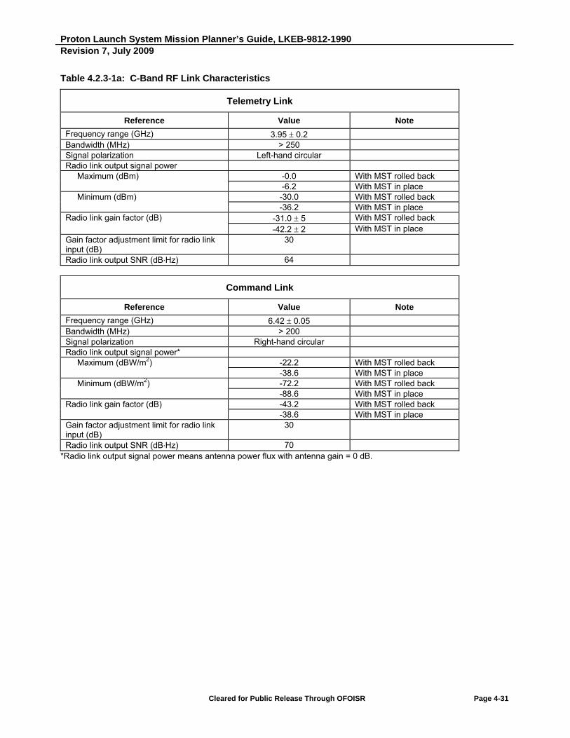
Proton Launch System Mission Planner’s Guide, LKEB-9812-1990 Revision 7, July 2009
Cleared for Public Release Through OFOISR Page 4-31
Table 4.2.3-1a: C-Band RF Link Characteristics
Telemetry Link
Reference Value Note
Frequency range (GHz) 3.95 0.2 Bandwidth (MHz) > 250 Signal polarization Left-hand circular Radio link output signal power Maximum (dBm) -0.0 With MST rolled back
-6.2 With MST in place Minimum (dBm) -30.0 With MST rolled back
-36.2 With MST in place Radio link gain factor (dB) -31.0 5 With MST rolled back
-42.2 2 With MST in place Gain factor adjustment limit for radio link input (dB)
30
Radio link output SNR (dB∙Hz) 64
Command Link
Reference Value Note
Frequency range (GHz) 6.42 0.05 Bandwidth (MHz) > 200 Signal polarization Right-hand circular Radio link output signal power* Maximum (dBW/m2) -22.2 With MST rolled back
-38.6 With MST in place Minimum (dBW/m2) -72.2 With MST rolled back
-88.6 With MST in place Radio link gain factor (dB) -43.2 With MST rolled back
-38.6 With MST in place Gain factor adjustment limit for radio link input (dB)
30
Radio link output SNR (dB∙Hz) 70 *Radio link output signal power means antenna power flux with antenna gain = 0 dB.
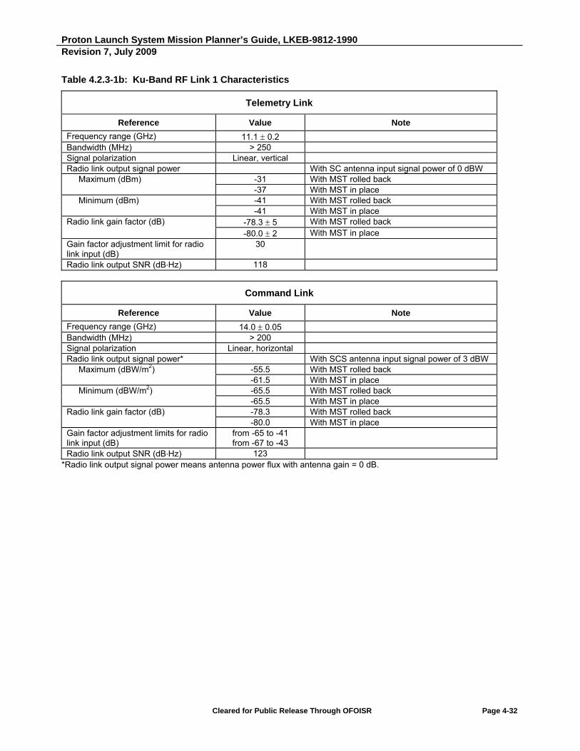
Proton Launch System Mission Planner’s Guide, LKEB-9812-1990 Revision 7, July 2009
Cleared for Public Release Through OFOISR Page 4-32
Table 4.2.3-1b: Ku-Band RF Link 1 Characteristics
Telemetry Link
Reference Value Note
Frequency range (GHz) 11.1 0.2 Bandwidth (MHz) > 250 Signal polarization Linear, vertical Radio link output signal power With SC antenna input signal power of 0 dBW Maximum (dBm) -31 With MST rolled back
-37 With MST in place Minimum (dBm) -41 With MST rolled back
-41 With MST in place Radio link gain factor (dB) -78.3 5 With MST rolled back
-80.0 2 With MST in place Gain factor adjustment limit for radio link input (dB)
30
Radio link output SNR (dB∙Hz) 118
Command Link
Reference Value Note
Frequency range (GHz) 14.0 0.05 Bandwidth (MHz) > 200 Signal polarization Linear, horizontal Radio link output signal power* With SCS antenna input signal power of 3 dBW Maximum (dBW/m2) -55.5 With MST rolled back
-61.5 With MST in place Minimum (dBW/m2) -65.5 With MST rolled back
-65.5 With MST in place Radio link gain factor (dB) -78.3 With MST rolled back
-80.0 With MST in place Gain factor adjustment limits for radio link input (dB)
from -65 to -41 from -67 to -43
Radio link output SNR (dB∙Hz) 123 *Radio link output signal power means antenna power flux with antenna gain = 0 dB.
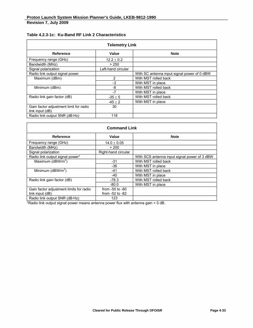
Proton Launch System Mission Planner’s Guide, LKEB-9812-1990 Revision 7, July 2009
Cleared for Public Release Through OFOISR Page 4-33
Table 4.2.3-1c: Ku-Band RF Link 2 Characteristics
Telemetry Link
Reference Value Note
Frequency range (GHz) 12.2 0.2 Bandwidth (MHz) > 250 Signal polarization Left-hand circular Radio link output signal power With SC antenna input signal power of 0 dBW Maximum (dBm) 2 With MST rolled back
-3 With MST in place Minimum (dBm) -8 With MST rolled back
-7 With MST in place Radio link gain factor (dB) -35 5 With MST rolled back
-45 2 With MST in place Gain factor adjustment limit for radio link input (dB)
30
Radio link output SNR (dB∙Hz) 118
Command Link
Reference Value Note
Frequency range (GHz) 14.0 0.05 Bandwidth (MHz) > 200 Signal polarization Right-hand circular Radio link output signal power* With SCS antenna input signal power of 3 dBW Maximum (dBW/m2) -31 With MST rolled back
-36 With MST in place Minimum (dBW/m2) -41 With MST rolled back
-40 With MST in place Radio link gain factor (dB) -78.3 With MST rolled back
-80.0 With MST in place Gain factor adjustment limits for radio link input (dB)
from -50 to -80 from -52 to -82
Radio link output SNR (dB∙Hz) 123 *Radio link output signal power means antenna power flux with antenna gain = 0 dB.

Proton Launch System Mission Planner’s Guide, LKEB-9812-1990 Revision 7, July 2009
Cleared for Public Release Through OFOISR Page 4-34
Table 4.2.3-1d: Ku-Band RF Link 3 Characteristics
Telemetry Link
Reference Value Note
Frequency range (GHz) 12.45 0.25 Bandwidth (MHz) > 500 Signal polarization Linear horizontal Radio link output signal power Maximum (dBm) -8.0 With service tower rolled back
-14.4 With service tower in place Minimum (dBm) -44.0 With service tower rolled back
-49.4 With service tower in place Radio link gain factor (dB) -74.0 With service tower rolled back
-79.4 With service tower in place Gain factor adjustment limit for radio link input (dB)
30
Radio link output SNR (dB∙Hz) 118
Command Link
Reference Value Note
Frequency range (GHz) 17.3 0.05 Bandwidth (MHz) > 200 Signal polarization Linear vertical Radio link output signal power* Maximum (dBW/m2) -59.0 With service tower rolled back
-59.1 With service tower in place Minimum (dBW/m2) -89.0 With service tower rolled back
-89.1 With service tower in place Radio link gain factor (dB) -93.0 With service tower rolled back
-96.0 With service tower in place Gain factor adjustment limit for radio link input (dB)
30
Radio link output SNR (dB∙Hz) 155 *Radio link output signal power means antenna power flux with antenna gain = 0 dB.

Proton Launch System Mission Planner’s Guide, LKEB-9812-1990 Revision 7, July 2009
Cleared for Public Release Through OFOISR Page 4-35
Table 4.2.3-1e: Ka-Band RF Link Characteristics
Telemetry Link
Reference Value Note
Frequency range (GHz) 18.3 0.01 Bandwidth (MHz) 100.0 Signal polarization circular Radio link output signal power Maximum (dBm) -11.0 With MST rolled back
-5.0 With MST in place Minimum (dBm) -41.0 With MST rolled back
-35.0 With MST in place Radio link gain factor (dB) -41.0 ± 5.0 With MST rolled back
-35.0 ± 5.0 With MST in place Gain factor adjustment limit for radio link input (dB)
30.0
Radio link output SNR (dB∙Hz) 68.0
Command Link
Reference Value Note
Frequency range (GHz) 29.374 0.12 Bandwidth (MHz) 100.0 Signal polarization any Radio link output signal power* Maximum (dBW/m2) -70.4 With MST rolled back
-67.4 With MST in place Minimum (dBW/m2) -100.4 With MST rolled back
-97.4 With MST in place Radio link gain factor (dB) -38.0 ± 3.0 With MST rolled back
-41.0 ± 3.0 With MST in place Gain factor adjustment limit for radio link input (dB)
30.0
Radio link output SNR (dB∙Hz) 45.0 *Radio link output signal power means antenna power flux with antenna gain = 0 dB.

Proton Launch System Mission Planner’s Guide, LKEB-9812-1990 Revision 7, July 2009
Cleared for Public Release Through OFOISR Page 4-36
4.2.4 Electrical Grounding
All payload preparation areas used by the SC, as well as launch base facilities used by the SC and SC EGSE, are equipped with earth-referenced steel ground busses with equipment attach points (threaded studs). The resistance between any point on these bars and the building earth ground is less than 4 ohms. The floor surfaces in the payload and hazardous payload processing areas is anti-static and connected to the facility grounding system. The SC contractor shall provide all cables and attachment hardware required to interconnect the SC and support equipment with facility grounds. SC grounding at the launch complex is affected via the serially-bonded adapter, Breeze M, and lower three Proton stages.
4.2.5 Electrical Bonding
The resistance across the SC/adapter separation plane shall not exceed 10 milliohms at a current less than 10 milliamperes, to be measured prior to the installation of separation pyrotechnics. This may be accomplished either by conductive surface contact between the SC and adapter interface ring (1666 adapters) here, the metal structures of the SC and the LV AS are irreversibly disconnected electrically during flight at the umbilical connector housings or by the use of two bonding straps which incorporate a friction contact connector that releases upon SC separation with a separation force of 40 N 5 N (as required by the SC Contractor). The outer surface of the transit cables will be made conductive and electrically joined to the LV body, with resistance not in excess of 1 milliohm.
4.2.6 SC/LV Lightning Protection
All payload preparation areas used by the SC (except the launch complex) will be equipped with a lightning protection system for direct and indirect hits. Augmentation of the standard provisions for any necessary SC individual circuit protection shall be provided by the SC contractor. The launch complex service tower will protect solely against direct lightning hits. Launch constraints preclude launching during a thunderstorm.
4.2.7 Electrostatic Discharge
During the entire flight through SC separation, no electrostatic discharge shall occur from either the LV or the SC surface through the LV-to-SC interface plane.
4.3 FITCHECK OF MECHANICAL/ELECTRICAL INTERFACES
A fitcheck of electrical/mechanical interfaces with the flight adapter and SC is required at the SC manufacturer’s facility for first-of-a-kind SC and the first follow-on SC in a series. Details are available in the ILS Fitcheck Release Test Philosophy document.
Proton Launch System Mission Planner’s Guide
SECTION 5
Mission Integration and Management


Proton Launch System Mission Planner’s Guide, LKEB-9812-1990 Revision 7, July 2009
Cleared for Public Release Through OFOISR Page 5-1
5. MISSION INTEGRATION AND MANAGEMENT
ILS provides the Customer with a Statement of Work (SOW), which defines the management approach for a Customer Launch Service Agreement (LSA), the deliverables provided to the Customer during the course of the LSA, and a schedule for all mission integration activities. This section highlights these provisions.
5.1 MANAGEMENT PROVISIONS
5.1.1 Key Personnel
Immediately after execution of each LSA, ILS, the Customer, KhSC, and the SC manufacturer shall designate their respective Program Directors who shall be responsible for performing all management functions related to the LSA.
ILS shall ensure that personnel necessary for the performance of this contract are made available to the
program to perform the work in a timely fashion and to satisfy requirements of the contract and its exhibits.
5.1.2 Interface Control Document
The Interface Control Document (ICD) shall be created by ILS based on a generic ICD template and the Customer-provided Interface Requirements Document (IRD). It will provide the Customer's technical requirements for the launch of their SC, and characteristics and constraints of the LV and launch site relating to the interface with the SC.
5.1.3 Schedule Management
ILS shall create and maintain an interface activities milestone schedule that provides all key technical interface milestones necessary for successful completion of the contract.
A typical mission integration schedule is shown in Figures 5.1.3-1a for a non-recurring, 24-month long program launching a first-of-a-kind SC which is manufactured on the basis of a new platform, or a platform that has never been launched on Proton M/Breeze M before. Figure 5.1.3-1b shows a recurring 18-month long program in which the SC is manufactured on the basis of a standard platform that has been launched on Proton M/Breeze M before. For recurring programs the integration schedule can be shortened (assuming hardware availability).
The typical meeting schedule and the deliverable milestones are provided in Section 5.1.5.1 and Section 5.2, respectively. This integrated program schedule for a particular program shall be presented and agreed upon between all parties at the Kickoff Meeting, and further changes shall be made, as necessary, and agreed upon at subsequent Technical Interchange Meetings (TIMs). In case of changes to internal schedules, the other parties shall be promptly informed.
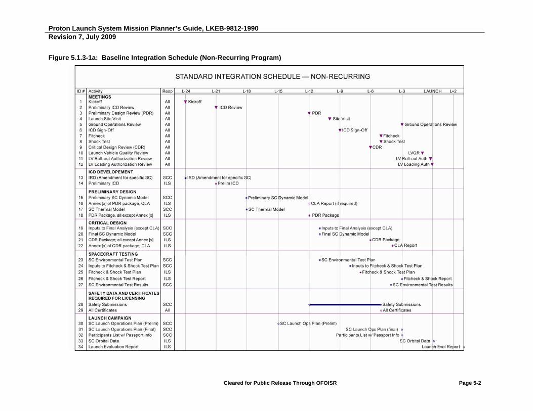
Proton Launch System Mission Planner’s Guide, LKEB-9812-1990 Revision 7, July 2009
Cleared for Public Release Through OFOISR Page 5-2
Figure 5.1.3-1a: Baseline Integration Schedule (Non-Recurring Program)

Proton Launch System Mission Planner’s Guide, LKEB-9812-1990 Revision 7, July 2009
Cleared for Public Release Through OFOISR Page 5-3
Figure 5.1.3-1b: Baseline Integration Schedule (Recurring Program)

Proton Launch System Mission Planner’s Guide, LKEB-9812-1990 Revision 7, July 2009
Cleared for Public Release Through OFOISR Page 5-4
5.1.4 Documentation Control and Delivery
ILS maintains an internal documentation and configuration control system for all LSAs. Deliverable documentation shall be maintained under this configuration control system.
All technical correspondence between ILS and the Customer relating to work on the LSA shall be strictly between the Customer Program Director and the ILS Program Director.
5.1.5 Meetings and Reviews
ILS, the Customer, KhSC and the SC manufacturer shall meet as often as necessary to allow good and timely execution of all activities related to launch preparation of each satellite. A preliminary meeting schedule is defined in Section 5.1.5.1, and meeting schedules will be updated through the course of the contract as part of the interface activities milestone schedule generated by ILS. Exact dates, locations, agendas, and participation are agreed upon in advance, on a case-by-case basis, by the ILS Program Director and the Customer Program Director.
5.1.5.1 Interface Meetings and Reviews
The ILS Program Director chairs all meetings unless otherwise specified. ILS shall provide meeting minutes at the end of each meeting, signed by ILS, the Customer, KhSC and the SC manufacturer.
A baseline meeting schedule is provided in Tables 5.1.5.1-1a and 5.1.5.1-1b for a non-recurring and recurring program, respectively. A non-recurring program is one with a first-of-a-kind SC that requires two analysis cycles. A recurring program is one with a similar SC, which requires only one analysis cycle and no significant changes to the LV and the launch site.
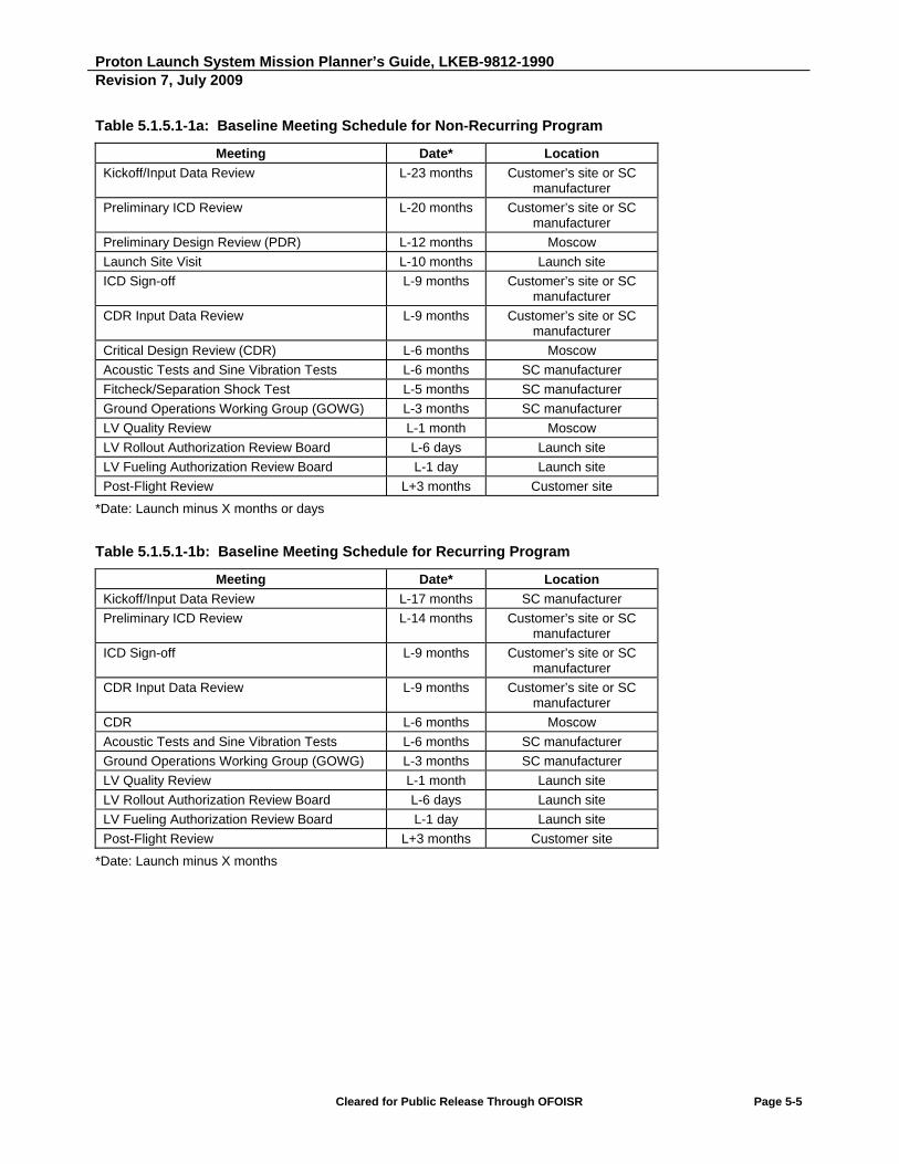
Proton Launch System Mission Planner’s Guide, LKEB-9812-1990 Revision 7, July 2009
Cleared for Public Release Through OFOISR Page 5-5
Table 5.1.5.1-1a: Baseline Meeting Schedule for Non-Recurring Program
Meeting Date* Location
Kickoff/Input Data Review L-23 months Customer’s site or SC manufacturer
Preliminary ICD Review L-20 months Customer’s site or SC manufacturer
Preliminary Design Review (PDR) L-12 months Moscow
Launch Site Visit L-10 months Launch site
ICD Sign-off L-9 months Customer’s site or SC manufacturer
CDR Input Data Review L-9 months Customer’s site or SC manufacturer
Critical Design Review (CDR) L-6 months Moscow
Acoustic Tests and Sine Vibration Tests L-6 months SC manufacturer
Fitcheck/Separation Shock Test L-5 months SC manufacturer
Ground Operations Working Group (GOWG) L-3 months SC manufacturer
LV Quality Review L-1 month Moscow
LV Rollout Authorization Review Board L-6 days Launch site
LV Fueling Authorization Review Board L-1 day Launch site
Post-Flight Review L+3 months Customer site
*Date: Launch minus X months or days
Table 5.1.5.1-1b: Baseline Meeting Schedule for Recurring Program
Meeting Date* Location
Kickoff/Input Data Review L-17 months SC manufacturer
Preliminary ICD Review L-14 months Customer’s site or SC manufacturer
ICD Sign-off L-9 months Customer’s site or SC manufacturer
CDR Input Data Review L-9 months Customer’s site or SC manufacturer
CDR L-6 months Moscow
Acoustic Tests and Sine Vibration Tests L-6 months SC manufacturer
Ground Operations Working Group (GOWG) L-3 months SC manufacturer
LV Quality Review L-1 month Launch site
LV Rollout Authorization Review Board L-6 days Launch site
LV Fueling Authorization Review Board L-1 day Launch site
Post-Flight Review L+3 months Customer site
*Date: Launch minus X months
Proton Launch System Mission Planner’s Guide, LKEB-9812-1990 Revision 7, July 2009
Cleared for Public Release Through OFOISR Page 5-6
A description of each type of meeting is provided below:
Kickoff/Input Data Review - This meeting represents the formal start of the program. A description of overall LSA services will be presented as well as management organization and preliminary program schedules. The IRD (SC input data) will be reviewed as a prelude to the generation of the ICD.
Preliminary ICD Review - The preliminary ICD will be reviewed and agreement reached on inputs to begin the preliminary analysis cycle.
PDR - ILS/KhSC will present all results of preliminary analyses and compare with ICD requirements.
Launch Site Visit - This visit to the launch site will provide a first orientation to the Customer on a non-recurring program. A key goal is to verify compliance with ICD requirements.
Operations Review - Review of requirements and corresponding implementation for launch base
operations.
CDR Inputs Review - Agreement will be reached at this meeting to all final analysis inputs prior to starting these analyses.
Acoustic Test - exposure of SC to acoustic environments expected during Proton LV launch.
Sine Vibration Test - exposure of SC to vibration environments in the 5 Hz to 100 Hz frequency range expected during Proton LV launch. Also used to validate the accuracy of the SC dynamic model.
Fitcheck - This is a fitcheck of flight adapter and separation system hardware to the flight SC at the SC manufacturer's facility.
Shock Test - This is an actuation of the flight type separation system with the flight SC at the manufacturer's facility. It is done in conjunction with the fitcheck.
CDR - ILS/KhSC presents all results from the final analysis cycle.
Launch Site Acceptance Review - This review is held at the launch site prior to SC arrival to confirm the
readiness of the launch site to begin the launch campaign. Compliance with requirements in the ICD will
be verified.
LV Quality Review - This meeting is held at KhSC as part of the quality control process. KhSC presents the quality status of all LV hardware per design documentation.
LV Rollout Authorization Review Board (State Commission Meeting) - A meeting is held at the launch site to confirm readiness to rollout the LV to the launch pad.
LV Fueling Authorization Review Board (State Commission Meeting) - A meeting is held at the launch site to confirm readiness to load the LV with propellants and confirm SC readiness to launch.
Post-Flight Meeting - This meeting is held at the Customer site to review data obtained during the launch campaign and during flight.

Proton Launch System Mission Planner’s Guide, LKEB-9812-1990 Revision 7, July 2009
Cleared for Public Release Through OFOISR Page 5-7
5.1.6 DTSA Oversight
ILS shall arrange for Defense Technology Security Administration (DTSA) oversight, as necessary, for technical interchange involving foreign nationals.
5.1.7 Quality Provisions
Refer to Appendix B for a description of Quality Assurance provisions in place for Proton launch services.
5.1.8 Launch License And Permits
ILS/KhSC shall obtain all necessary Russian Federation permits and approvals required for the processing and launch of the Customer's SC.
The Customer shall obtain permits and approvals required to import and export the SC and associated equipment from its country of origin through the Port of Entry in Russia and Kazakhstan.
5.2 ILS DELIVERABLES
ILS provides the following deliverables during the course of each LSA. A representative delivery schedule is provided in Table 5.2-1.

Proton Launch System Mission Planner’s Guide, LKEB-9812-1990 Revision 7, July 2009
Cleared for Public Release Through OFOISR Page 5-8
Table 5.2-1: ILS Deliverable Schedule for a Recurring and a Non-Recurring Program
Document Recurring Non-Recurring
Date Date
ICD Development
Preliminary ICD L-14 months L-20 months
Signed ICD L-9 months L-9 months
Preliminary Design
PDR package Not Applicable L-12 months
Critical Design
CDR package L-6 months L-6 months
SC Testing
Sine Vibration Test (Notching) Plan Inputs L-7 months L-7 months
Fitcheck and Shock Test Plan Not Applicable L-7 months
5.2.1 ICD Development
5.2.1.1 ICD
ILS shall provide the ICD and will maintain it by issuing revisions, as necessary. The preliminary ICD will contain input data for the preliminary design effort. The signed ICD will contain input data for the critical design effort.
5.2.2 Preliminary and Critical Design
ILS/KhSC shall conduct all performance and mission analyses required for the proper implementation of the Customer’s launch mission, as discussed below.
The following analyses are conducted during the mission integration effort for each satellite launch mission. For first-of-a-kind SC, one preliminary and one final analysis cycle will normally be conducted during each satellite integration effort. For follow-on SC, one analysis cycle will normally be performed; where the SC and/or LV relevant parameters have changed significantly, two cycles will be conducted.
Each cycle includes the analyses defined in Table 5.2.2-1.

Proton Launch System Mission Planner’s Guide, LKEB-9812-1990 Revision 7, July 2009
Cleared for Public Release Through OFOISR Page 5-9
Table 5.2.2-1: Design Review Analyses
No. Title Description
1 Design and Manufacturing A summary of the LV design concentrating on differences with previous vehicles. Emphasis is on specificities in adapter and payload compartment design to meet specific SC payload requirements.
2 Mission Design The flight design, including maneuvers and maneuver sequence, orbit parameters and dispersions, collision avoidance.
3 Thermal Analysis Integrated thermal analysis of combined operations (ground and flight) for SC and LV hardware to ensure thermal compatibility. The SC mathematical model is provided by the Customer per the Thermal Model Specification provided by ILS.
4 Separation Analysis Analysis of SC separation, including presentation of pertinent kinematic parameters and their dispersions during the separation event.
5 CLA/Acoustic/ Shock Loads Environment
1) Dynamic CLA. The SC mathematical model is furnished by the Customer according to the ILS-provided Dynamic Model Specification. The following events are analyzed:
a) Lift-off
b) Flight winds and gust
c) First/second stage separation
For follow-on satellites of the same configuration, only one verification CLA will be conducted unless significant LV configuration changes have occurred.
2) Presentation of other load environments, including acoustic, shock and ground transportation loads.
6 Contamination Analysis of ground and flight contamination sources and effect on SC payload.
7 RF Link and EMC Analysis of the RF link between the Bunker and the pad, and EMC analysis verifying compatibility between the SC and LV systems.
8 Clearance Analysis Clearance analysis between the SC and the LV during flight to verify sufficient dynamic clearances.
9 Venting Analysis Analysis of fairing depressurization during flight.
10 Operations Detailed description of how KhSC will meet operational requirements specified by the Customer in the ICD.
11 Reliability and Quality Assurance
Description of measures to assure reliability and quality of ILV components. Certify ILV launch.
12 Telemetry System Structure of the telemetry system and the ground telemetry complex.
13 SC Electrical Interface to SC EGSE
Description of onboard cable network.
14 Ground Cable Network and Power Supply
Description of the ground cable network, power supply, and electrical interfaces.

Proton Launch System Mission Planner’s Guide, LKEB-9812-1990 Revision 7, July 2009
Cleared for Public Release Through OFOISR Page 5-10
A softcopy of all design documentation will be provided to the Customer two weeks prior to the review.
Reports shall be provided documenting the results of the above analyses. These reports shall be provided for each analysis cycle and include the following topics: summary of results, detail of analyses performed, and comparison of analysis results with ICD requirements. The analyses required may be reduced in scope if agreed upon between ILS and the Customer.
5.2.3 SC Sine Vibration/Acoustic/Fitcheck/Shock Tests Support
ILS shall provide an overall plan describing the Fitcheck/Shock Test and a description of the responsibilities and actions for each of the participants including KhSC, ILS, the SC manufacturer and Customer.
ILS shall also provide inputs to support the SC manufacturer’s Sine Vibration and Acoustic tests.
5.2.4 Data Provided After Launch
5.2.4.1 Orbital Data
ILS/KhSC shall provide the state vector data as described in Section 2.
5.2.4.2 Post-Flight Report
ILS/KhSC shall provide a post-flight report for each LSA documenting the results of ground processing of the SC and the subsequent flight.
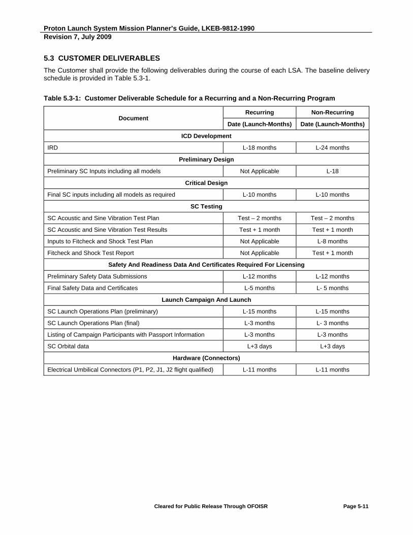
Proton Launch System Mission Planner’s Guide, LKEB-9812-1990 Revision 7, July 2009
Cleared for Public Release Through OFOISR Page 5-11
5.3 CUSTOMER DELIVERABLES
The Customer shall provide the following deliverables during the course of each LSA. The baseline delivery schedule is provided in Table 5.3-1.
Table 5.3-1: Customer Deliverable Schedule for a Recurring and a Non-Recurring Program
Document Recurring Non-Recurring
Date (Launch-Months) Date (Launch-Months)
ICD Development
IRD L-18 months L-24 months
Preliminary Design
Preliminary SC Inputs including all models Not Applicable L-18
Critical Design
Final SC inputs including all models as required L-10 months L-10 months
SC Testing
SC Acoustic and Sine Vibration Test Plan Test – 2 months Test – 2 months
SC Acoustic and Sine Vibration Test Results Test + 1 month Test + 1 month
Inputs to Fitcheck and Shock Test Plan Not Applicable L-8 months
Fitcheck and Shock Test Report Not Applicable Test + 1 month
Safety And Readiness Data And Certificates Required For Licensing
Preliminary Safety Data Submissions L-12 months L-12 months
Final Safety Data and Certificates L-5 months L- 5 months
Launch Campaign And Launch
SC Launch Operations Plan (preliminary) L-15 months L-15 months
SC Launch Operations Plan (final) L-3 months L- 3 months
Listing of Campaign Participants with Passport Information L-3 months L-3 months
SC Orbital data L+3 days L+3 days
Hardware (Connectors)
Electrical Umbilical Connectors (P1, P2, J1, J2 flight qualified) L-11 months L-11 months
Proton Launch System Mission Planner’s Guide, LKEB-9812-1990 Revision 7, July 2009
Cleared for Public Release Through OFOISR Page 5-12
5.3.1 ICD Development
The Customer shall provide an IRD to ILS with interface requirements describing all pertinent design information, including SC characteristics, mechanical and electrical interfaces, and constraints necessary to define the integration tasks and mission operation. This will be used to generate the preliminary ICD.
5.3.2 Preliminary and Critical Design
5.3.2.1 SC Dynamic Model
The Customer shall provide a SC dynamic model conforming to the requirements in Appendix C.
5.3.2.2 SC Thermal Model
The Customer shall provide a SC thermal model conforming to the requirements in Appendix C.
5.3.2.3 SC Fluid Slosh Model
The Customer shall provide a SC fluid slosh model conforming to the requirements in Appendix C.
5.3.2.4 SC CAD Model
The Customer shall provide a CAD model of the SC conforming to the requirements in Appendix C.
5.3.3 SC Testing
5.3.3.1 SC Acoustic and Sine Vibration Test Plans and Results
The Customer shall provide a test plan for ILS approval documenting the tests, including Sine Vibration and Acoustics tests that will be performed by the SC manufacturer to demonstrate compatibility with the Proton ground and flight environments. A summary of the results from these tests will be provided at test completion.
5.3.3.2 Fitcheck/Shock Test Plan, Procedures and Report
The Customer shall provide input to the ILS Fitcheck/Shock Test Plan. The Customer shall provide a SC summary report following the fitcheck and shock test documenting the results.
Proton Launch System Mission Planner’s Guide, LKEB-9812-1990 Revision 7, July 2009
Cleared for Public Release Through OFOISR Page 5-13
5.3.4 Required Safety Data and Certificates
5.3.4.1 Safety Submissions
The Customer shall provide to ILS a SC and GSE Safety Data Package, as well as other safety certificates, required to certify that the SC systems, GSE and procedures are safe during all operations at Baikonur, and during flight up to SC separation from the Breeze M. Safety certificates are to be provided per the dates and formats specified in the Proton Launch Campaign Certificates Template Document.
5.3.5 Launch Campaign and Launch
5.3.5.1 SC Launch Operations Plan
The Customer shall provide a plan that describes the SC launch operations at the launch site.
5.3.5.2 Listing of Campaign Participants
The Customer shall provide a list of all potential campaign participants three months prior to launch with all required passport information. This list will designate primary and backup personnel. This information will be included in the access list that will be provided to the Russian Government for approval. Personnel whose names are not on this access list will be denied access to the Baikonur Cosmodrome.
5.3.5.3 Orbital Data
The Customer shall provide SC state vector data complying with requirements in Section 2.
5.4 SPECIFIC CUSTOMER RESPONSIBILITIES
For each LSA, the Customer has the following responsibilities.
5.4.1 Launch Campaign Duration
The launch campaign duration from Campaign Team arrival to departure should not exceed 45 days.
5.4.2 SC and Associated Ground Equipment
The Customer shall provide at the launch site the SC and associated ground equipment and personnel required to meet the contracted launch date.
5.4.3 Final SC Data
Prior to the commencement of joint operations, the Customer shall supply the actual satellite dry and wet
masses.
5.4.4 SC Readiness
The Customer shall provide a readiness to proceed with operations prior to the start of combined operations; prior to rollout to the pad; and prior to fueling of the LV. These dates will be coordinated with the Baikonur operations schedule.

Proton Launch System Mission Planner’s Guide, LKEB-9812-1990 Revision 7, July 2009
Cleared for Public Release Through OFOISR Page 5-14
5.4.5 Removal of Associated Ground Equipment
Unless prior arrangements have been made, the Customer shall remove from the Baikonur Cosmodrome all of its associated ground equipment using Customer-provided charter aircraft within three days after launch.
5.4.6 Evaluation of LV And Associated Services
As soon as practical after launch, the Customer shall provide to ILS all relevant available data from the launch necessary to assist ILS in evaluating the performance of the LV and associated services provided under each LSA.
5.4.7 SC Propellants
The Customer shall procure SC propellants to support the launch campaign and is responsible for shipment of these propellants to the Port of Entry into Russia (St. Petersburg) and through Customs. After the launch campaign, the Customer shall be responsible for removal of the propellants and associated equipment from the Port of Entry. ILS/KhSC will assist the Customer with Customs clearance procedures.
5.4.8 Connectors
The Customer shall provide flight and test connectors per mission specific requirements. These connectors will be used for the assembly of flight and test harnesses.
5.5 ILS SERVICES AND MATERIAL SPECIFICALLY EXCLUDED
ILS has no obligation to provide the following goods or services:
a) Receiving inspection of SC elements and support equipment upon arrival at the launch site.
b) Analysis of data generated by the SC through its own telemetry system.
c) The SC support consoles.
d) Shipping cost associated with the SC, its components, GSE and support equipment (except at the launch site).
e) SC RF checkout equipment (i.e., antennas, coaxial cables and checkout consoles).
f) Replacement parts for the SC or its support equipment.
g) Installation, handling, or other responsibility related to SC pyrotechnic systems or elements.
h) Responsibility for SC grounding and bonding before mating with the Contractor PLA.
i) Functional operation or installation of the airborne SC control circuits while at the Launch Complex.
j) Any tracking or commanding of the SC after separation from the LV.
Proton Launch System Mission Planner’s Guide, LKEB-9812-1990 Revision 7, July 2009
Cleared for Public Release Through OFOISR Page 5-15
k) SC propellants.
l) Fueling services for the Customer's aircraft used for delivery and return shipment of SC-related equipment.
m) Propellant sampling analysis facilities at or near the launch site are not equipped with equipment or technology necessary for analysis of SC propellants. The Customer must plan for shipment and analysis of samples outside the Russian Federation if these analyses are required.
n) Spacecraft equipment calibration services at the launch site.
o) Analysis and prediction of SC orientation, kinematic parameters and orbit parameters are not provided beyond the moment of separation.
p) Storage of SC and all its Ancillary Equipment after arrival at the launch site in excess of the period set forth in Paragraph 5.1.3 of the mission-specific Proton Launch Services Statement of Work (SOW).
q) Storage of propellants after arrival at the launch site in excess of the period set forth in Paragraph 5.1.2.2.
r) Additional analyses over and above those specified in previous sections, caused by changes to the SC design which are not in any way attributable to the Contractor and which are not required by the terms of the LSA.
s) Additional analyses over and above those required in previous sections, caused by launch postponements attributed to the Customer (unless otherwise specified in the postponement provisions of the LSA).
t) Changes to the LV and/or the launch site facilities as described in this document or the Proton Launch Campaign Guide (PLCG), caused by changes to the SC design which are not in any way attributable to the Contractor and not required by the terms of the LSA.
u) Repeated launch campaign in the event that the initial launch campaign was discontinued for any reason not attributable to the Contractor (unless otherwise provided for in the postponement provisions of the LSA).

Intentionally Blank

Proton Launch System Mission Planner’s Guide
SECTION 6
Spacecraft and Launch Facilities


Proton Launch System Mission Planner’s Guide, LKEB-9812-1990 Revision 7, July 2009
Cleared for Public Release Through OFOISR Page 6-1
6. SPACECRAFT AND LAUNCH FACILITIES
6.1 FACILITIES OVERVIEW
The Baikonur Cosmodrome is located in the Republic of Kazakhstan in Central Asia, approximately 2,000 km southeast of Moscow. The Cosmodrome is a Russian facility leased from Kazakhstan through the year 2050. The annual temperature averages 13oC, ranging from -40oC in winter to +45oC in summer. The Baikonur Cosmodrome is equipped with spur-railroad service lines that are used for most transportation. Specialized equipment is available for fueling, handling of compressed gases, and for SC integration with the AU and the LV.
The Baikonur Cosmodrome includes several facilities that are used for ILS launch campaigns (see Figure 6.1-1). These facilities include:
a) Yubileiny Airfield - SC arrival, GSE and campaign personnel arrival and departure via chartered aircraft.
b) Building 92A-50 - SC preparation, AU and LV preparation, and final integration of AU to LV.
c) Breeze M Fueling Station - Fueling of the Breeze M as part of Integrated Launch Vehicle (ILV).
d) Launch Complex Areas 81 and 200 - Launch from Pad 24 (Area 81) or Pad 39 (Area 200).
e) Hotel Area (Area 95) - Hotel Fili and Hotel Kometa for use by commercial Customers.
The sub-sections that follow provide brief descriptions of these facilities. More in-depth descriptions of these same facilities are provided later in this section.
6.1.1 Yubileiny Airfield
Yubileiny Airfield is located at the Baikonur Cosmodrome and is used for receiving the charter aircraft carrying the SC and GSE, as well as charter flights with campaign personnel. It is an internationally rated airport with a single 4.5 km long, 84 m wide landing strip oriented 60 degrees/240 degrees relative to North. The airport has an elevation of approximately 100 m above sea level.
A 140 m by 420 m concrete pad is available next to a railhead for unloading aircraft and transferring equipment to rail convoys. Prior to aircraft arrival, this area is cleared and ground-handling equipment is positioned. The pad also is equipped with stationary and portable lighting for use in night operations.

Proton Launch System Mission Planner’s Guide, LKEB-9812-1990 Revision 7, July 2009
Cleared for Public Release Through OFOISR Page 6-2
Figure 6.1-1: Baikonur Facilities Map

Proton Launch System Mission Planner’s Guide, LKEB-9812-1990 Revision 7, July 2009
Cleared for Public Release Through OFOISR Page 6-3
6.1.2 Building 92A-50
Building 92A-50 contains all facilities necessary for processing a SC from its arrival through its mating with the adapter and Breeze M, and encapsulation. The SC and GSE containers arrive at Hall 102, where they are cleaned. The SC container is transported on a flatbed railcar into Hall 101, where the SC container is off-loaded from the railcar and the SC is normally removed from the container. The SC is then transported into Hall 103A on the SC transporter or manufacturer supplied dolly, where it is installed onto its fueling/test stand. The SC remains in this hall for all subsequent testing and fueling operations. Following fueling, the SC is transported back to Hall 101 where it is mated to the adapter and Breeze M and encapsulated. Following encapsulation, the AU is transported to Hall 111 for integration with the Proton M LV and final electrical verification of the integrated LV.
6.1.3 Breeze M Fueling Station (Area 92)
The ILV will be transported to the Breeze M fueling facility for filling the Breeze M with low pressure propellant components, and from there to the launch complex (Area 81 or 200).
6.1.4 Launch Complexes (Area 81/Area 200)
At the launch complexes, an underground Vault accommodates the SC Customer’s support equipment providing power to the SC while on the pad (Rooms 64/76 for Launch Pad 24, and Room 79 for Launch Pad 39).
6.1.5 Hotels
The Hotels Kometa, Fili, and Polyot, which are located in Area 95 near the launch complexes, are used to house personnel during a launch campaign.

Proton Launch System Mission Planner’s Guide, LKEB-9812-1990 Revision 7, July 2009
Cleared for Public Release Through OFOISR Page 6-4
6.2 SC PROCESSING FACILITIES - BUILDING 92A-50
This section describes the SC processing facilities, which provide the capability to perform all required operations from receipt of the SC through its encapsulation in preparation for launch on the Proton LV at the Baikonur Cosmodrome. These operations include off-loading in the SC technical zone, testing, fueling, mating to the Breeze M, payload encapsulation, and LV integration.
The main building within the technical complex for integration and testing is Building 92A-50. Stand-alone processing and assembly of the Proton M LV are carried out in Hall 111. SC preparation, testing, and fueling are accomplished in Hall 103A. Integration of the fueled SC with the Breeze M and subsequent encapsulation in the PLF to form the AU are performed in Hall 101. The AU is transferred by rail to the LV side of the building in Hall 111, where it is horizontally mated to the three assembled stages of the Proton to form the integrated LV.
6.2.1 Facility Layout and Area Designations
Building 92A-50 has been expressly modified and outfitted to efficiently complete all SC processing and encapsulation in a single building. The halls/rooms, facility systems, and equipment are sized to accommodate SC of up to approximately 4.5 m diameter, 10.0 m height, and loaded masses of up to 8,700 kilograms.
Building 92A-50 is approximately 229 m long and 147 m wide, but only a portion of the building is used for commercial programs. Figure 6.2.1-1 depicts the overall arrangement of the areas within the building that are used for commercial programs.
The receiving area (Hall 102) is the primary entrance for the SC and associated equipment, and is located on the east side of the building. The SC shipping container is cleaned in the receiving area, Hall 102. The container is then delivered into Hall 101 on a railcar, where it is lifted and placed on the floor. After the railcar exits and the environment is reestablished, the SC is removed from the shipping container and placed on a transporter to be moved into the processing and fueling hall (Hall 103A). Once there, the SC is placed on the fueling stand and requires no further movement in order to complete all necessary standalone assembly, checkout, propellant loading, and pneumatics servicing. When ready, the fueled SC is moved by special transport dolly to the integration hall (Hall 101) for mating to the Breeze M and encapsulation inside the PLF.
The main entry into Building 92A-50 for ILS and SC processing personnel is next to Hall 103A, on the west end of the building. An additional entrance with a vestibule is provided for delivery of equipment into the control room.
To connect Customer’s equipment, 60 Hz and 50 Hz Uninterrupted Power Supply (UPS) sockets are available in the rooms and at workstations, providing transient-free, conditioned power. (For a detailed specification, refer to the Proton Launch Campaign Guide.)
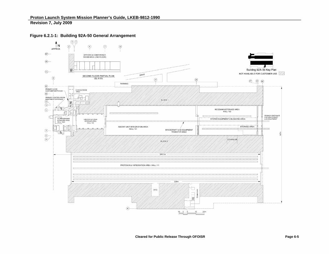
Proton Launch System Mission Planner’s Guide, LKEB-9812-1990 Revision 7, July 2009
Cleared for Public Release Through OFOISR Page 6-5
Figure 6.2.1-1: Building 92A-50 General Arrangement

Proton Launch System Mission Planner’s Guide, LKEB-9812-1990 Revision 7, July 2009
Cleared for Public Release Through OFOISR Page 6-6
6.2.2 Receiving/Storage Area - Hall 102
The receiving area (Hall 102), or the integration area (Hall 101), may be used to off-load the SC container from its transport railcar. Rail access for the SC and GSE is provided through two locally controlled, exterior sliding doors located in the hall’s east wall. Hall 102 is used for wash-down of the railcar and container before transfer to Hall 101. It can also be used for container storage. See Figure 6.2.2-1 for a detailed layout of Hall 102.
The overall clear dimensions of Hall 102 are approximately 70.5 m by 36 m. Hall 102 is equipped with two overhead cranes for handling operations. Each of the two cranes is equipped with hooks for 50 MT and 10 MT. The clear ceiling height is 25.85 m, and the heights of the overhead crane hooks are 17.5 m and 18.25 m, respectively (see Figure 6.2.2-2). The SC unloading area is approximately 8.85 m wide and 34.1 m long. An area of approximately 240 square meters is provided for general storage of non-hazardous items (no environmental controls).
When ready, the SC container is moved, via railcar, from Hall 102 to the inside of Hall 101, where the container is opened and the SC is transferred to its own transport dolly, and moved into Hall 103A.
Figure 6.2.2-1: Detailed Layout of Hall 102

Proton Launch System Mission Planner’s Guide, LKEB-9812-1990 Revision 7, July 2009
Cleared for Public Release Through OFOISR Page 6-7
Figure 6.2.2-2: 50-MT and 10-MT Crane Hooks in Hall 102
Proton Launch System Mission Planner’s Guide, LKEB-9812-1990 Revision 7, July 2009
Cleared for Public Release Through OFOISR Page 6-8
6.2.3 SC Processing and Fueling Hall - Hall 103A (Room 4101)
Hall 103A, the processing and fueling hall, is used for pre-encapsulation SC processing, including loading propellants and servicing pneumatics (see Figure 6.2.3-1). Equipment access to Hall 103A is provided from Hall 103 through two sliding doors with a clear opening that is 9.5 m wide by 11.95 m high. A 15-MT overhead bridge crane, equipped with a load cell device, is provided.
The clear dimensions for Hall 103A are 11.5 m wide by 22 m long. Rooms 4114 and 4116 provide rapid egress routes from Hall 103A, and the pressurization airlock (Room 4110) provides the standard egress route. Rooms 4114 and 4116 each have three emergency showers and eyewashes. The Self-Contained Atmospheric Protective Ensemble (SCAPE) shower areas (Rooms 4121 and 4122) have showers for post-operation clean-up. A parking lot for ambulances and fire trucks is located next to the rapid egress routes. The pressurization airlock (Room 4110) and the space between the double doors between Hall 103 and Hall 103A are pressurized with clean air in order to isolate Hall 103A during propellant loading operations.
An 8 m by 8 m fueling island, located on the west side of Hall 103A, is used for oxidizer and fuel transfer operations. It is surrounded by a grating-covered trench, which drains any fuel or oxidizer spills into separate waste tanks. The grating permits the passage of wheeled dollies. The hall is equipped with a vapor monitoring system, emergency ventilation, fire-suppression system, demineralized and distilled water, gaseous nitrogen (GN2) supply systems, breathing air supply systems, fuel and oxidizer vapor intakes, systems for localized removal of fuel component vapors, and a compressed air supply system.
The floor of Hall 103A has an anti-static coating and a load rating of 10-MT (3,000 kg/cm2) per truck axle. All finishes in Hall 103A use materials that do not react with propellants.
The wall between Hall 103A and Hall 103 includes a pair of large doors designed to withstand a 60 kg/m2 overpressure load.

Proton Launch System Mission Planner’s Guide, LKEB-9812-1990 Revision 7, July 2009
Cleared for Public Release Through OFOISR Page 6-9
Figure 6.2.3-1: Building 92A-50 Spacecraft Processing and Fueling Area

Proton Launch System Mission Planner’s Guide, LKEB-9812-1990 Revision 7, July 2009
Cleared for Public Release Through OFOISR Page 6-10
6.2.4 Integration Area - Hall 101
Once the SC has been processed and fueled in Hall 103A, it is transported to the integration area (Hall 101), which is an ISO Class 8 cleanroom. Hall 101 is used to assemble the Ascent Unit (AU), which involves the following operations:
a) Mating the SC, adapter and Breeze M
b) SC/adapter/Breeze M continuity checks
c) Rollover of the assembled SC, adapter and Breeze M to horizontal
d) Encapsulation within the PLF
Two remotely controlled overhead bridge cranes (50-/10-MT hooks) are used to transfer the SC from the transport dolly to the adapter and to the Breeze M on the rollover fixture, as well as transferring the integrated AU from the rollover fixture to a railcar for delivery to Hall 111, LV integration facility.
This hall is also used for stand-alone processing of the Breeze M prior to integration of the AU.
Hall 101 is 34.5 m wide and 107 m long. It has a full-height wall and ceiling facing, as well as door sealing, thermal insulation, and an anti-static floor coating. See Figure 6.2.4-1 for a detailed layout of Hall 101.

Proton Launch System Mission Planner’s Guide, LKEB-9812-1990 Revision 7, July 2009
Cleared for Public Release Through OFOISR Page 6-11
Figure 6.2.4-1: Detailed Layout of Hall 101
Proton Launch System Mission Planner’s Guide, LKEB-9812-1990 Revision 7, July 2009
Cleared for Public Release Through OFOISR Page 6-12
6.2.5 Fuel and Oxidizer Conditioning Rooms - Rooms 4112 and 4105
Room 4112, the fuel conditioning room, is used for temporary storage of the SC fuel (e.g., monomethyl hydrazine (MMH)) and thermal conditioning of the fuel before loading. Room 4105, the oxidizer conditioning room, is used for temporary storage of the SC oxidizer (e.g., nitrogen textroxide (NTO)) and thermal conditioning of the oxidizer before loading. Both rooms have grounding points and the capability to collect and dispose of propellant spills. Room 4112 contains no materials that react with fuel, and Room 4105 contains no materials that react with oxidizer. Rooms 4105 and 4112 are equipped with a vapor monitoring system, emergency ventilation, demineralized and distilled water, nitrogen supply systems, breathing air supply systems, fuel and oxidizer vapor aspirators, systems for localized removal of fuel component vapors, and a compressed air supply system.
The floors in both rooms have an anti-static coating and a load rating of 10-MT (3,000 kg/cm2) per truck axle. The floor elevations are the same as Room 4101.
Rooms 4105 and 4112 are approximately 5.7 m long and 4.4 m wide, and both have clear ceiling heights of 2.9 m.
6.2.6 Fuel and Oxidizer Equipment Decontamination Rooms - Rooms 4111 and 4115
Room 4111, the fuel equipment decontamination room, is used to decontaminate the fuel loading equipment. Room 4115, the oxidizer equipment decontamination room, is used to decontaminate oxidizer loading equipment. Both rooms have the capability to collect and dispose of propellant spills. Room 4111 contains no materials that react with fuel, and Room 4115 incorporates no materials that react with oxidizer. Rooms 4111 and 4115 are equipped with a vapor monitoring system, emergency ventilation, demineralized and distilled water, nitrogen supply systems, breathing air supply systems, grounding points, fuel and oxidizer vapor aspirators, systems for localized removal of fuel component vapors, and a compressed air supply system.
Rooms 4111 and 4115 are both 6.1 m long and 4.1 m wide, and both have clear ceiling heights of 2.95 m.

Proton Launch System Mission Planner’s Guide, LKEB-9812-1990 Revision 7, July 2009
Cleared for Public Release Through OFOISR Page 6-13
6.2.7 Control Room - Room 4102
Room 4102, the control room, is used for monitoring and controlling SC processing and fueling activities in Hall 103A, as well as SC integration in Hall 101 with the Breeze M, AU integration with the LV in Hall 111 and SC monitoring of the Breeze M fueling area.
A blast-resistant viewing window is provided between the control room and Hall 103A for monitoring all processing and fueling operations. The wall between Hall 103A and the control room is a welded, reinforced steel structure that provides a hermetic seal.
Ten sealable inlets are provided between the control room and Hall 103A for routing the cables that support processing and fueling of the SC. The inlet design precludes ingress of air contaminated with propellant components from migrating from Hall 103A into the Control Room 4102 area.
The control room is 5.9 m by 12.9 m in overall dimension, with a clear ceiling height of 3.1 m. An equipment entry vestibule, with inner and outer doors 2.9 m wide and 2.9 m high, is provided to facilitate equipment movement into the control room.
The floors of the control room and all associated access corridors are designed for wheeled dollies. Forklifts may be used to bring equipment into the vestibule of the room, but they are not permitted to operate in the control room itself. Temporary ramps are available to aid moving items from the entrance vestibule into the control room.
This room is the primary SC control room for launch operations once the LV reaches the pad. The Customer may alternatively use the Bunker (see Section 6.4) for SC control while at the launch pad.
6.2.8 Entrance/Lobby Area
The entrance/lobby area includes the following rooms and features:
a) A street-level entrance
b) Break room (Room 0301)
c) Medical office (Room 0302)
d) SC Customer security checkpoint with viewing windows and security sensor alarm panel (Room 0318)
e) Tool storage room (Room 0319)
f) Restroom (Room 0320)
6.2.9 Change Room Area
The change room area consists of several rooms (Rooms 0303 - 0317), including independent men’s and women’s restrooms, and change areas, a storage and issue room for cleanroom garments, a Personal Protective Equipment (PPE) storage and donning room, and a corridor with an air shower. Clean passage is available from the change rooms to either Hall 103 or Hall 103A. A detailed layout of the change room area is shown in Figure 6.2.9-1.

Proton Launch System Mission Planner’s Guide, LKEB-9812-1990 Revision 7, July 2009
Cleared for Public Release Through OFOISR Page 6-14
Figure 6.2.9-1: Detailed Layout of Change Room Area
Proton Launch System Mission Planner’s Guide, LKEB-9812-1990 Revision 7, July 2009
Cleared for Public Release Through OFOISR Page 6-15
6.2.10 Pressurization Airlock - Room 4110
The pressurization airlock provides clean access between the air shower (Room 0317) and Hall 103A. During propellant loading operations in Hall 103A, the airlock is pressurized slightly more than Hall 103A to prevent vapor migration from Hall 103A. SCAPE-suited personnel use the airlock to access the SCAPE showers and doffing rooms, and the pressurization airlock and corridor to the air shower and change rooms can be used as an emergency egress route from Hall 103A, if necessary.
Room 4110 is 1.4 m by 3.5 m wall-to-wall.
6.2.11 SCAPE Donning/Doffing Rooms and Showers - Rooms 4108, 4109, 4121 and 4122
The SCAPE donning and doffing rooms, Rooms 4108 for fuel and 4109 for oxidizer, are available for donning and doffing PPE for a propellant loading operation. As necessary, SCAPE showers, Rooms 4121 for fuel and 4122 for oxidizer, are available to decontaminate the PPE suits before doffing. The dedicated showers are plumbed to the respective liquid waste tanks.
Room 4108 is approximately 1.65 m by 3.0 m and Room 4109 is approximately 1.9 m by 5.4 m. Room 4121 is 1.2 m by 3.4 m and Room 4122 is 1.2 m by 3.4 m.
6.2.12 Clean Storage Hall - Hall 103
Hall 103, the clean storage hall, provides accessible storage for clean items supporting SC processing. It also provides an ISO Class 8 corridor between Halls 101 and 103A.
Access is via equipment doors leading to/from Hall 101 and 103A.
The wall-to-wall dimensions of the clean storage hall (Hall 103) are 17.5 m by 31.8 m at floor level, and the ceiling height is 15 m. At heights greater than 3 m above the floor, the width of Hall 103 is restricted by Heating, Ventilation and Air Conditioning (HVAC) ducting to about 16 m.
6.2.13 Ordnance Storage
KhSC provides limited storage of ordnance required to support a launch campaign. The ordnance storage room may be accessed through a door located in the north wall of Hall 101.

Proton Launch System Mission Planner’s Guide, LKEB-9812-1990 Revision 7, July 2009
Cleared for Public Release Through OFOISR Page 6-16
Ordnance to be stored must meet the following criteria:
a) A maximum Trinitrotoluen (TNT) equivalent quantity of 50 grams, requiring a volume no more than 60 cm by 60 cm by 60 cm, may be stored in accordance with Russian Federation Standards.
b) Only insensitive explosives are permitted, and each item must be individually packaged in U.S. Department of Transportation-approved shipping and storage containers.
c) The SC Customer must provide a certificate of conformance to the Hazard of Electromagnetic Radiation to Ordnance (HERO) Specification (MIL-I-23659).
6.2.14 Offices and Conference Room Area - Rooms 1202 through 1209
An office/conference room area (Rooms 1202 - 1209) is located on the second floor of Building 92A-50. See Figure 6.2.14-1 for a detailed layout. The functions of the eight constituent rooms are:
a) Security office (Room 1202)
b) ILS office (Room 1203)
c) Support/Interpreter office (Room 1204)
d) DTSA office (Room 1204A)
e) SC manufacturer office (Room 1205)
f) SC manufacturer office (Room 1206)
g) Customer office (Room 1207)
h) Conference rooms (Rooms 1208/1209)
The clear dimensions of these rooms are as follows:
a) Offices - Rooms 1202 through 1207, 8.9 m by 5.9 m (each)
b) Conference Room 1208/1209, 8.9 m by 11.9 m (each)
c) Clear height of all rooms, 3.1 m
Restrooms are accessible from the corridor serving the office/conference room area; general access to the area is via stairs from the “street” entrance to the change room area. As a safety precaution, during SC propellant loading and Breeze M propellant loading, only essential personnel are permitted in Building 92A-50.
Two egress routes are available from the area: the normal route at the western end of the room block that exits to the “street” entrance to the change room area; and an emergency evacuation route that exits east through the KhSC area of the building. A 2,000 kg capacity freight elevator, with a 1.8-m wide by 2.2-m high door opening and floor measuring 2.0 m by 3.0 m, is also available in the KhSC work area.
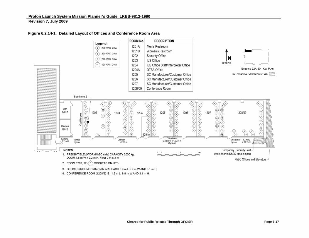
Proton Launch System Mission Planner’s Guide, LKEB-9812-1990 Revision 7, July 2009
Cleared for Public Release Through OFOISR Page 6-17
Figure 6.2.14-1: Detailed Layout of Offices and Conference Room Area
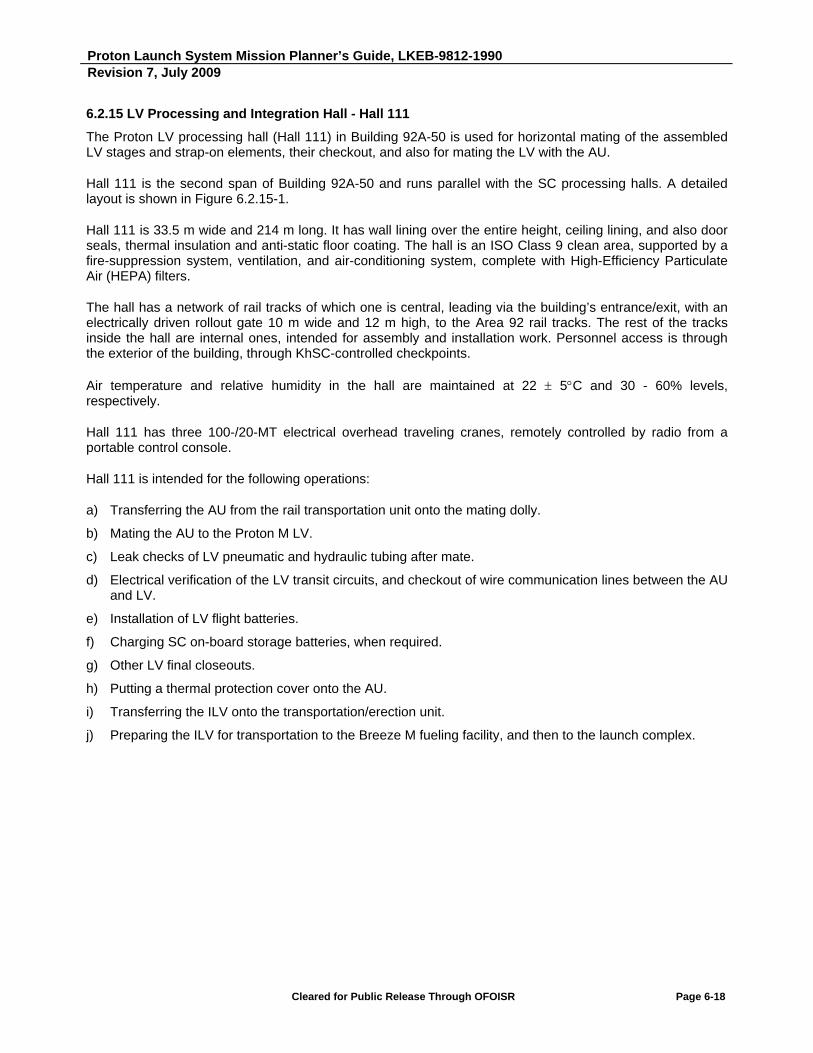
Proton Launch System Mission Planner’s Guide, LKEB-9812-1990 Revision 7, July 2009
Cleared for Public Release Through OFOISR Page 6-18
6.2.15 LV Processing and Integration Hall - Hall 111
The Proton LV processing hall (Hall 111) in Building 92A-50 is used for horizontal mating of the assembled LV stages and strap-on elements, their checkout, and also for mating the LV with the AU.
Hall 111 is the second span of Building 92A-50 and runs parallel with the SC processing halls. A detailed layout is shown in Figure 6.2.15-1.
Hall 111 is 33.5 m wide and 214 m long. It has wall lining over the entire height, ceiling lining, and also door seals, thermal insulation and anti-static floor coating. The hall is an ISO Class 9 clean area, supported by a fire-suppression system, ventilation, and air-conditioning system, complete with High-Efficiency Particulate Air (HEPA) filters.
The hall has a network of rail tracks of which one is central, leading via the building’s entrance/exit, with an electrically driven rollout gate 10 m wide and 12 m high, to the Area 92 rail tracks. The rest of the tracks inside the hall are internal ones, intended for assembly and installation work. Personnel access is through the exterior of the building, through KhSC-controlled checkpoints.
Air temperature and relative humidity in the hall are maintained at 22 5C and 30 - 60% levels, respectively.
Hall 111 has three 100-/20-MT electrical overhead traveling cranes, remotely controlled by radio from a portable control console.
Hall 111 is intended for the following operations:
a) Transferring the AU from the rail transportation unit onto the mating dolly.
b) Mating the AU to the Proton M LV.
c) Leak checks of LV pneumatic and hydraulic tubing after mate.
d) Electrical verification of the LV transit circuits, and checkout of wire communication lines between the AU and LV.
e) Installation of LV flight batteries.
f) Charging SC on-board storage batteries, when required.
g) Other LV final closeouts.
h) Putting a thermal protection cover onto the AU.
i) Transferring the ILV onto the transportation/erection unit.
j) Preparing the ILV for transportation to the Breeze M fueling facility, and then to the launch complex.
Proton Launch System Mission Planner’s Guide, LKEB-9812-1990 Revision 7, July 2009
Cleared for Public Release Through OFOISR Page 6-19
Figure 6.2.15-1: Hall 111 Layout
Proton Launch System Mission Planner’s Guide, LKEB-9812-1990 Revision 7, July 2009
Cleared for Public Release Through OFOISR Page 6-20
6.3 BREEZE M FUELING FACILITY
Following final assembly, the ILV is transported from Building 92A-50 to the Breeze M fueling facility. The fueling facility is located in Area 92, directly adjoining Building 92A-50, with some 70 m distance between the building and the facility’s external fencing. The fueling facility has been upgraded and reequipped to satisfy the needs of the SC manufacturers and contractors, and is capable of supporting any operation required for SC health checkout and SC on-board storage battery recharging during the ILV stay at the facility.
The fueling facility is used for filling Breeze M tanks with propellant components at low-pressure (high-pressure components are filled earlier at Area 31). The area has a dead siding of the standard rail track and a paved road for motor vehicles. In the filling area, the facility has an awning 66 m long, 12 m wide and 11 m high, built of metal truss structures, with wind protection at the sides. The fueling facility is complete with lightning protection and grounding. The work area has explosion-proof lighting. The fueling facility layout is shown in Figure 6.3-1.
For accommodating the equipment for low-rate charging SC on-board storage batteries and checking the health of SC on-board systems, a special facility 5.9 m long, 4.7 m wide and 2.5 m high (battery charging station) is located about 40 m from the LV tail end. The facility has a hinged gate 2 m wide and 2.3 m high for equipment entry, and a personnel access door. The facility’s walls are thermally insulated and soundproof. An air conditioning system supports the required temperature and humidity (see Section 3.1.1) and can be switched over from plenum and exhaust circulation to internal air circulation. The facility offers security and fire alarm signaling, a fire-fighting system, telephone communication, and general and emergency illumination.
The facility supports electrical and fiber-optic communication with the SC control room in Building 92A-50, and 380/220 V, 50 Hz or 208/120 V, 60 Hz power supply for the SC equipment. Appropriate monitoring and measuring instruments are available for propellant component vapor detection.
To safeguard against unauthorized access to the PLF doors, the fueling facility has a close-circuit security TV system.
A thermal control car supports the required temperature, humidity and environment for the encapsulated SC at the fueling facility.

Proton Launch System Mission Planner’s Guide, LKEB-9812-1990 Revision 7, July 2009
Cleared for Public Release Through OFOISR Page 6-21
Figure 6.3-1: Breeze M Fueling Area Layout

Proton Launch System Mission Planner’s Guide, LKEB-9812-1990 Revision 7, July 2009
Cleared for Public Release Through OFOISR Page 6-22
6.4 LAUNCH COMPLEX FACILITIES
Following fueling of the low-pressure tanks of the Breeze M, the ILV is transported to the Proton launch complex for erection, checkout and launch. There are two complexes with two launch pads available for commercial users:
- Area 81, Launch Pad 24
- Area 200, Launch Pad 39
6.4.1 Area 81 Launch Complex
6.4.1.1 Launch Pad 24 - General Description
Following integration, the ILV is transported to the launch complex, Pad 24, in Area 81 for erection and launch. Figure 6.4.1.1-1 shows a layout of the launch complex. The launch area includes the following physical facilities, units, and systems that support processing and launching of the Proton ILV:
a) Launch structure with launch pad (including underground Vault)
b) Mobile Service Tower (MST)
c) Bunker (Rooms 250 and 251)
d) Facilities for support systems
UPS 208/120 V, 60 Hz and 380/220 V, 50 Hz power supplies at the launch complex will be provided from an independent special power supply system. (Refer to the Proton Launch Campaign Guide for details.)
The launch complex facilities have electrical sockets for connecting Customer's equipment.
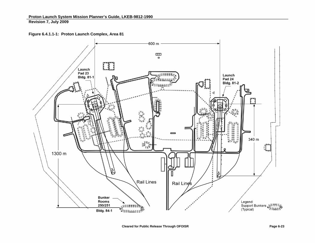
Proton Launch System Mission Planner’s Guide, LKEB-9812-1990 Revision 7, July 2009
Cleared for Public Release Through OFOISR Page 6-23
Figure 6.4.1.1-1: Proton Launch Complex, Area 81

Proton Launch System Mission Planner’s Guide, LKEB-9812-1990 Revision 7, July 2009
Cleared for Public Release Through OFOISR Page 6-24
6.4.1.2 Facility Layout and Area Designations
6.4.1.2.1 Launch Structure with Launch Pad (Including Underground Vault)
The launch structure and Vault house equipment that supports the pre-launch processing of the ILV. They provide electrical, pneumatic, and hydraulic links between the ground system testing equipment and on-board hardware via transit cables and pipes. The launch structure is designed to withstand the first-stage engine plume impingement. The launch pad is intended for ILV installation, erection, and securing in a vertical position.
6.4.1.2.2 Room 64 - Vault
Room 64 can be used to house the SC Customer’s GSE. Room 64 measures approximately 5.1 m by 5.6 m and is equipped with 50/60 Hz electrical power, grounding, and communications services. All launch campaign operations requiring the presence of personnel in the Vault must be completed prior to the start of LV fueling, which occurs approximately seven hours prior to launch. All personnel are required to leave the Vault by this time, and from then on, all Vault equipment must be controlled remotely.
6.4.1.2.3 Room 76 - Vault
Room 76 can be used to house the SC Customer’s GSE. Room 76 measures approximately 5.4 m by 10.8 m and is equipped with 50/60 Hz electrical power, grounding, and communications services. All launch campaign operations requiring the presence of personnel in the Vault must be completed prior to the start of LV fueling, which occurs approximately seven hours prior to launch. All personnel are required to leave the Vault by this time, and from then on, all Vault equipment must be controlled remotely.
6.4.1.2.4 Mobile Service Tower
The MST provides access to the SC and ILV and houses equipment to support SC and ILV pre-launch processing and launch. The MST includes service platforms, a gallery, service fixtures, two cargo/passenger elevators (500 kg rated load capacity each), and two cranes (rated load capacity 500 kg and 5,000 kg, respectively). An overall view of the MST is provided in Figure 6.4.1.2.4-1.
6.4.1.2.5 Rooms 250/251 - Bunker
The Bunker (Rooms 250/251) is used to support a Proton launch. It is located 1.3 km from the launch pad and provides protection for personnel and equipment during the launch. The Bunker houses the ILV System Test Equipment (STE). If required, it can also house the SC STE and GSE required for pre-launch operations and monitoring of SC readiness. Air temperature and humidity inside the Bunker are controlled by an air conditioning unit. While the Bunker can be used to house GSE for pre-launch operations, it is not recommended due to its close proximity to the launch pad.

Proton Launch System Mission Planner’s Guide, LKEB-9812-1990 Revision 7, July 2009
Cleared for Public Release Through OFOISR Page 6-25
Figure 6.4.1.2.4-1: Proton Mobile Service Tower

Proton Launch System Mission Planner’s Guide, LKEB-9812-1990 Revision 7, July 2009
Cleared for Public Release Through OFOISR Page 6-26
6.4.2 Area 200 Launch Complex
6.4.2.1 Launch Pad 39 - General Description
Pad 39 is located 5 km to the southeast of Pad 24. Figure 6.4.2.1-1 shows a layout of the launch complex. The launch area includes the following physical facilities, units, and systems that support processing and launching of the Proton ILV:
a) Launch structure with launch pad (including underground Vault)
b) MST
c) Bunker (Room 246)
d) Facilities for support systems
UPS 208/120 V, 60 Hz and 380/220 V, 50 Hz power supplies are provided at the launch complex from an independent special power supply system.
The launch complex facilities have electrical sockets for connecting Customer's equipment.
6.4.2.2 Facility Layout and Area Designations
6.4.2.2.1 Launch Structure with Launch Pad (Including Underground Vault)
The launch structure and Vault house equipment that supports the pre-launch processing of the ILV. They provide electrical, pneumatic, and hydraulic links between the ground system testing equipment and on-board ILV hardware via transit cables and pipes. The launch structure is designed to withstand the first-stage engine plume impingement. The launch pad is intended for ILV installation, erection, and securing the ILV in a vertical position.
6.4.2.2.2 Room 79 - Vault
Room 79 can be used to house the SC Customer’s GSE. Room 79 measures approximately 8.75 m by 5.7 m and is equipped with 50 Hz and 60 Hz electrical power supplies, grounding, and communications services. All launch campaign operations requiring the presence of personnel in the Vault must be completed prior to the start of LV fueling, which occurs approximately seven hours prior to launch. All personnel are required to leave the Vault by this time, and from then on, all Vault equipment must be controlled remotely.

Proton Launch System Mission Planner’s Guide, LKEB-9812-1990 Revision 7, July 2009
Cleared for Public Release Through OFOISR Page 6-27
Figure 6.4.2.1-1: Proton Launch Complex, Area 200
Proton Launch System Mission Planner’s Guide, LKEB-9812-1990 Revision 7, July 2009
Cleared for Public Release Through OFOISR Page 6-28
6.4.2.2.3 Mobile Service Tower
The MST provides access to the SC and integrated LV and houses equipment to support SC and ILV pre-launch processing and launch. The MST includes service platforms, a gallery, service fixtures, two cargo-passenger elevators (500 kg rated load capacity each), and two cranes (rated load capacity 500 kg and 5,000 kg, respectively). An overall view of the MST is provided in Figure 6.4.1.2.4-1.
6.4.2.2.4 Room 246 - Bunker
The Bunker (Room 246) is used to support a Proton launch. It is located 1.5 km from the launch pad and provides protection for personnel and equipment during the launch. The Bunker houses the ILV STE. If required, it can house the SC STE and GSE required for pre-launch operations and monitoring of SC readiness. Air temperature and humidity inside the Bunker are controlled by an air-conditioning unit. While the Bunker can be used to house GSE for pre-launch operations, it is not recommended due to its close proximity to the launch pad.
6.4.3 Time Countdown
A time countdown system is available for displaying the countdown information and Universal Time (GMT) at various locations in the launch complex:
In operations at Pad 24, the time countdown system is accommodated in Building 84-1 (Bunker).
In operations at Pad 39, the time countdown system is accommodated in Building 201-1 (Bunker).
For information readout, digital displays are situated as follows:
Technical Complex:
- Building 92A-50, in Room 4102
Launch Complex 81 (Pad 24):
- Building 84-1, in Room 251
- Buildings 81-1, 81-2, in Rooms 76
Launch Complex 200 (Pad 39):
- Building 201-1, in Room 246
- Building 200-2, in Room 79
The time countdown system will be activated no earlier than ten days ahead of the launch time, and will supply information (time) on a digital display at 1-minute increments.
At 45 minutes prior to launch time, the time countdown system will switch over to display time at 1-second increments.

Proton Launch System Mission Planner’s Guide, LKEB-9812-1990 Revision 7, July 2009
Cleared for Public Release Through OFOISR Page 6-29
6.5 COMMUNICATIONS SERVICES
This section describes the telecommunications support that KhSC provides for commercial launch campaigns at the Baikonur Cosmodrome. In general, KhSC has overall technical responsibility for configuring and maintaining these services at the Cosmodrome. For details on hardware locations at individual facilities, refer to the facility-specific sections of the Proton Launch Campaign Guide (PLCG).
Specific telecommunications requirements for any given launch campaign are provided by the SC Customer in the mission-specific ICD. The final Launch Campaign Service Order communications inputs defined in the ICD shall be provided by the Customer 90 days prior to the start of the Launch Campaign. Nominally, all communications support is in place no later than one week prior to the start of a campaign and remains fully operational until three days following launch.
6.5.1 International Voice/Data Transmission
Voice/data transmission capacity from the KhSC earth station at Baikonur Cosmodrome to the U.S. and other international locations is procured by ILS by direct subcontract with the long distance service provider. The task order with the long distance service provider shall be completed by ILS no later than two months prior to the first use of the service for domestic (United States) Customers, and no later than three months prior to first use of service for international Customers. Upon ILS request, KhSC provides the long distance service provider with the necessary technical information regarding the interface and test support for link checkouts prior to handing the links over to the SC Customer. Testing of ILS-procured long distance lines shall be completed no later than one week prior to the first use of the service.
A SC Customer telecommunications specialist must be available at Baikonur during SC telecommunications equipment installation and communications link testing and commissioning. The Baikonur-London satellite link time slot numbers for the lines listed in Table 6.5.1.1-1 shall be specified in the ICD.
6.5.1.1 Types of Lines (Termination Other Than Moscow)
Table 6.5.1.1-1 summarizes the typical telecommunication lines that can be provided for international voice/data transmission during any given launch campaign. Additional types of communication lines are available. Specific support requirements are detailed in the mission-specific ICD.
Table 6.5.1.1-1: Typical International Voice/Data Transmission Lines Available to Launch Campaigns
Type of Line Usage
64 kbps channel E-mail or secure FAX or voice
64 kbps channel 4 x 16 kbps compressed voice/FAX channels
64 kbps clear channel Data transmission
Proton Launch System Mission Planner’s Guide, LKEB-9812-1990 Revision 7, July 2009
Cleared for Public Release Through OFOISR Page 6-30
Links are established from the KhSC ground station at the Baikonur Cosmodrome through a Russian satellite (Express AM1) to London, and then by fiber optics from London to the long-distance service provider at a European or domestic Point Of Presence (POP). From the POP, the lines are routed via a dedicated line to a location defined by the SC Customer. ILS also leases several 64 kbps lines from Baikonur to Reston, Virginia. These lines are provided by the long-distance service provider, as described above, and reconfigured for 4 x 16 kbps voice channels. Additional lines in Reston, VA may be made available for Customer lease.
6.5.1.2 Multiplexing
KhSC multiplexes the above lines using an Alcatel 3600 Mainstreet Multiplexer (MUX), equipped with an echo suppression function for each line. Should the SC manufacturer require the use of special MUX equipment, they must provide KhSC with detailed information about the Definity Private Branch Exchange (PBX) interface, signaling protocol, dialing connection procedures, and provide all necessary adapting equipment to ensure compatibility with the Definity PBX. The list of adapting equipment needs to be agreed upon with KhSC not later than 3 months prior to the start of the launch campaign. KhSC will assist the Customer in installing such equipment.
6.5.1.3 Access to Baikonur PBX
All commutated lines mentioned above have access to the Baikonur PBX and a Baikonur Cosmodrome dial tone, which allows automatic switching to/from any SC Customer phone jack location or to/from any mobile radio. No operator assistance is required for international calls. The exact locations of all phone jacks are specified in the facilities section of the PLCG.
6.5.2 On-Site Mobile and PBX Phone Network Communications
Table 6.5.2.1-1 summarizes the telecommunications equipment that KhSC and ILS provide for a launch campaign.
At each Area 95 hotel, one analog voice circuit is provided in each room, each recreation area, and each bar/eating area. Two (2) analog voice/FAX circuits are provided in the reception area of each hotel.
In work areas, a minimum of 20 digital handsets and 50 analog handsets can be provided for ILS and Customer use, and can be distributed to the jacks designated in the facilities section of the PLCG.
The specific phone jacks to be used by the SC Customer are identified in the mission-specific ICD. Final agreement on telecommunications requirements shall be reached with KhSC no later than 45 days prior to the launch campaign.
6.5.2.1 Voice/FAX
Table 6.5.2.1-1 summarizes the quantities and types of equipment provided by KhSC for voice communications.

Proton Launch System Mission Planner’s Guide, LKEB-9812-1990 Revision 7, July 2009
Cleared for Public Release Through OFOISR Page 6-31
Table 6.5.2.1-1: KhSC/ILS-Provided Communications Equipment
Equipment Model Provider Quantity Used By
Customer ILS Total
Portable radios Motorola 838 Model B4
KhSC 6* 11* 17*
Portable radio with telephone keyboard
Motorola 838 Model B7
KhSC 7* 16* 23*
Analog telephone (work areas) AT&T KhSC 36* 14* 50*
Digital telephone with speaker AT&T KhSC 14* 6* 20*
Analog telephone (hotel rooms) AT&T KhSC Each room
SCAPE radios QB-3R/TR/IS KhSC 4 - 4 Note: *Additional quantities may be negotiated on a mission-specific basis.
6.5.2.2 Teleconference Networks
ILS and the Customer have access to two dial-in voice networks functioning as intercom networks for each campaign. One dial-in network can support a maximum of seven callers, while the second can be configured to support a maximum of 14 callers. SC Customers are advised to notify ILS/KhSC a minimum of two days in advance of establishing an intercom network. These networks are accessible from any of the phone jacks and mobile phones, as well as from offsite (international) lines.
6.5.2.3 Mobile Radios
Motorola MTX838 B7 portable radios (with keypads) operate through a Motorola SmartWorks trunking system and have access to international lines (access is limited by number of digits in number dialed), as well as phone jacks used by the SC Customer and ILS. Their operational range includes all areas where Customer/ILS personnel are located, including the airfield. The Motorola MTX838 B4 radios (without keypads) can send calls only to other radios in the same area, but can receive from B7 radios and telephones in other areas. During SC fueling operations in Building 92A-50, Hall 103A, Customer personnel are provided with explosion-proof portable radios, ensuring two-way communication during work in SCAPE.
Nominally, each mobile radio is programmed for the two channels for SC Customer/ILS use. Table 6.5.2.1-1 identifies the numbers of mobile radios supplied by KhSC for a launch campaign.

Proton Launch System Mission Planner’s Guide, LKEB-9812-1990 Revision 7, July 2009
Cleared for Public Release Through OFOISR Page 6-32
6.5.2.4 Data
Data transfer within the Baikonur facility, as well as to Customer offsite facilities, can be made via a digital network. The use of the following data interfaces is possible: V.35 (64 kbps) and Integrated Services Digital Network (ISDN) BRI S/T (2B+D). RJ45 jacks installed at the launch sites facilities are used to form these interfaces. The Customer is required to supply the appropriate interface equipment to adapt to these digital standards, or the Customer may elect to use analog modems. The Customer will specify termination points required for each digital link in the mission-specific ICD.
Up to four pairs of hardline connections may be provided between the Vault and the Bunker to support modem links to Customer electrical test equipment in the Vault. An ISDN termination is not available in the Vault.
In Building 92A-50, a hardline distribution network is provided between the office areas, control room, and Hall 103A to provide the SC Customer with the option of creating a computer network among these areas.
Access to the Internet is provided through a Moscow Internet Service Provider (ISP) to the hotel areas and Building 92A-50.
6.5.3 Baikonur CCTV Network
Figure 6.5.3-1 provides a schematic diagram of the Closed-Circuit Television (CCTV) network.
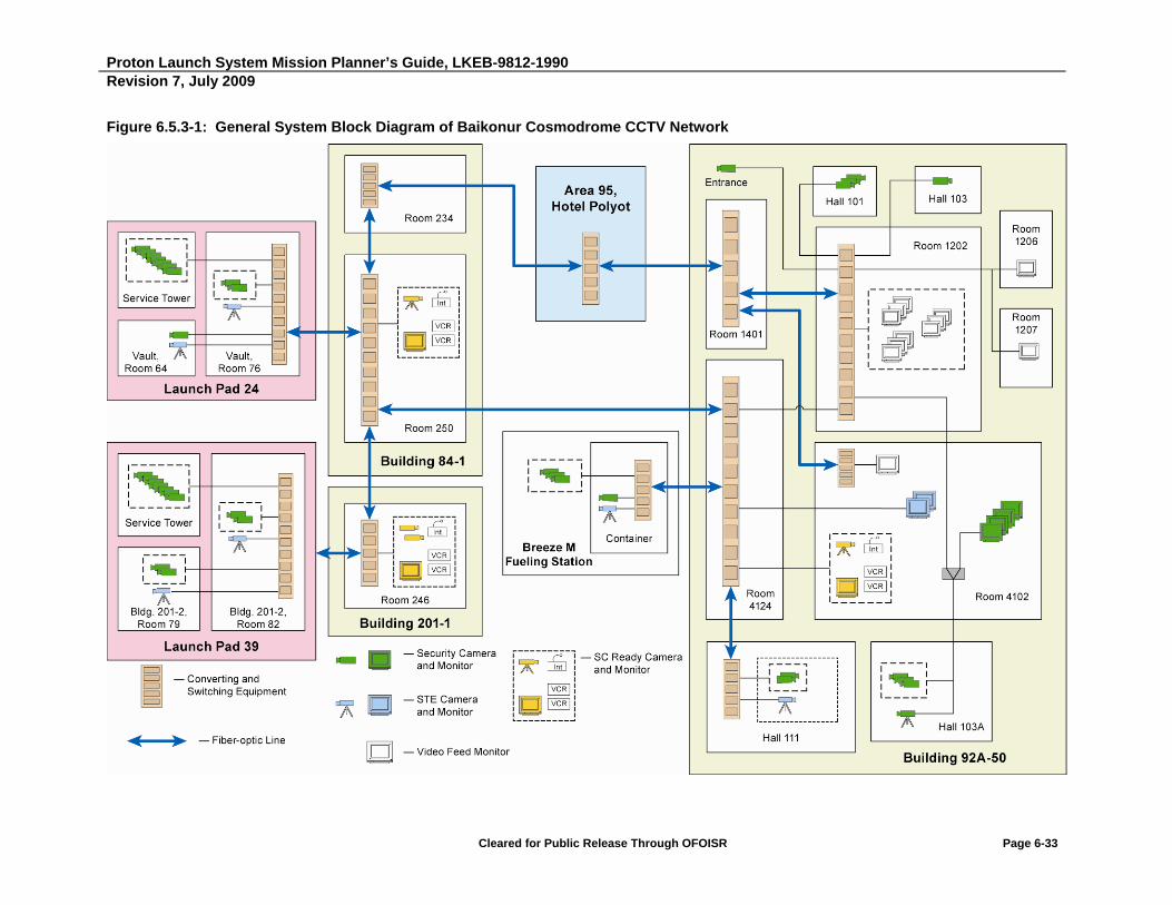
Proton Launch System Mission Planner’s Guide, LKEB-9812-1990 Revision 7, July 2009
Cleared for Public Release Through OFOISR Page 6-33
Figure 6.5.3-1: General System Block Diagram of Baikonur Cosmodrome CCTV Network
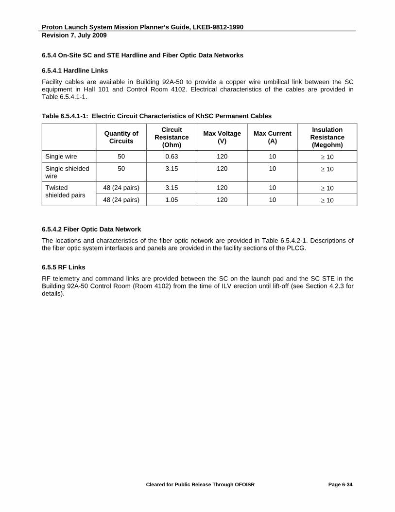
Proton Launch System Mission Planner’s Guide, LKEB-9812-1990 Revision 7, July 2009
Cleared for Public Release Through OFOISR Page 6-34
6.5.4 On-Site SC and STE Hardline and Fiber Optic Data Networks
6.5.4.1 Hardline Links
Facility cables are available in Building 92A-50 to provide a copper wire umbilical link between the SC equipment in Hall 101 and Control Room 4102. Electrical characteristics of the cables are provided in Table 6.5.4.1-1.
Table 6.5.4.1-1: Electric Circuit Characteristics of KhSC Permanent Cables
Quantity of
Circuits
Circuit Resistance
(Ohm)
Max Voltage (V)
Max Current (A)
Insulation Resistance (Megohm)
Single wire 50 0.63 120 10 10
Single shielded wire
50 3.15 120 10 10
Twisted shielded pairs
48 (24 pairs) 3.15 120 10 10
48 (24 pairs) 1.05 120 10 10
6.5.4.2 Fiber Optic Data Network
The locations and characteristics of the fiber optic network are provided in Table 6.5.4.2-1. Descriptions of the fiber optic system interfaces and panels are provided in the facility sections of the PLCG.
6.5.5 RF Links
RF telemetry and command links are provided between the SC on the launch pad and the SC STE in the Building 92A-50 Control Room (Room 4102) from the time of ILV erection until lift-off (see Section 4.2.3 for details).

Proton Launch System Mission Planner’s Guide, LKEB-9812-1990 Revision 7, July 2009
Cleared for Public Release Through OFOISR Page 6-35
Table 6.5.4.2-1: Fiber Optic Data Links
From Number of Lines
To Notes Building
(Room) Interface Building (Room) Interface
92A-50 (4102)
ST Fiber Optic Coupler
6 Breeze M Fueling Station ST Fiber Optic Coupler
Flexible switching (n x 2 lines to any destination)
92A-50 (4102)
ST Fiber Optic Coupler
8 Bunker (Room 250, Area 81)/ Bunker (Room 246, Area 200)/ 92A-50 (101, Work Site 1)/ 92A-50 (101, Work Site 2)/ 92A-50 (111, Work Site 1)/ 92A-50 (111, Work Site 2)/ Pad 24, Vault (Rooms 64 or 76)/ Pad 39, Vault (Room 79)
ST Fiber Optic Coupler
Flexible switching (n x 2 lines to any destination)
92A-50 (4102)
TCP/IP (RJ45 Connector)
2 Breeze M Fueling Station 92A-50 (111, Work Site 1)/ 92A-50 (111, Work Site 2)/ Pad 24, Vault (Rooms 64 or 76)/ Pad 39, Vault (Room 79)
TCP/IP (RJ45 Connector)
Data transmission lines “Control room - Vault (LP 24, LP 39)” and “Control Room - Breeze M Fueling Station” cannot be supported simultaneously.

Intentionally Blank

Proton Launch System Mission Planner’s Guide
SECTION 7
Launch Campaign

Proton Launch System Mission Planner’s Guide, LKEB-9812-1990 Revision 7, July 2009
Cleared for Public Release Through OFOISR Page 7-1
7. LAUNCH CAMPAIGN
7.1 ORGANIZATIONAL RESPONSIBILITIES
Many organizations are involved in a Launch Campaign (see Figure 7.1-1). What follows is a brief overview of the responsibilities of the primary organizations.
7.1.1 Khrunichev
Overall responsibility for coordinating work performed at the launch complex by Roscosmos.
Engineering support and quality inspection for all testing performed on Stages 1 to 3 of the Launch Vehicle (LV), as well as the adapters and fairing. KhSC is also responsible for Breeze M engineering, inspection and test.
Maintenance of Buildings 92A-50 and the hotel complex.
Transportation and food services.
Coordinating Baikonur Cosmodrome and the town of Baikonur medical services with Roscosmos.
Integration facility security.
7.1.2 Rosсosmos
Maintenance of the Breeze M fueling area and the launch complex.
Provision of technicians for performing LV testing.
Provision of quality inspectors.
LV operations from integration in Building 92A-50, Hall 111 through erection on pad and launch.
Launch complex security.

Proton Launch System Mission Planner’s Guide, LKEB-9812-1990 Revision 7, July 2009
Cleared for Public Release Through OFOISR Page 7-2
Figure 7.1-1: Organization During Launch Campaign

Proton Launch System Mission Planner’s Guide, LKEB-9812-1990 Revision 7, July 2009
Cleared for Public Release Through OFOISR Page 7-3
7.1.3 ILS
Prime interface between the Customer and KhSC.
Coordinating campaign schedules and operations with the SC Customer and KhSC.
Logistics.
Safety overview as an advisory function to SC and Customer management.
Physical security of SC assets while at Baikonur processing facilities.
Translation and interpretation services.
Medical staff and emergency medical evacuation.
Compliance with U.S. regulations and licenses.
7.1.4 SC Customer
SC checkout and processing at the Baikonur Cosmodrome.
7.2 CAMPAIGN ORGANIZATION
7.2.1 Contractual and Planning Organization
The fundamental contractual relationships among the principal parties in a launch campaign are as follows:
a) ILS is a contractor to the SC Customer.
b) KhSC is a subcontractor to ILS.
All matters that could potentially affect the terms of the Launch Service Agreement (LSA) (the contract) between a SC Customer and ILS will be coordinated by the SC Customer and ILS. Matters affecting the terms of the subcontract between ILS and KhSC will be resolved by ILS and KhSC. In particular, any issues involving possible additional costs must be mutually agreed upon through these contractual relationships.
ILS will coordinate all logistics support and operations planning with both the SC Customer and KhSC.
ILS may assign a Mission Manager to monitor any operation to ensure that all activities are carried out in conformance with the mutually agreed upon Safety Plan. This Mission Manager is present for all hazardous operations.

Proton Launch System Mission Planner’s Guide, LKEB-9812-1990 Revision 7, July 2009
Cleared for Public Release Through OFOISR Page 7-4
7.2.2 Organization During Combined Operations
Combined operations are those operations involving some combination of SC Customer organization, ILS, and KhSC personnel (e.g., KhSC adapter mating, Breeze M to payload mating, encapsulation, AU checkout, AU integration to mated Stages 1/2/3, and any other operations on the pad which require PLF access). For each such combined operation, one operation leader is assigned, either from KhSC or the SC Customer. This individual directs the operation and ensures that it is carried out in conformance with the mutually agreed upon procedures.
For each operation, one person from the SC Customer organization, ILS and KhSC is designated as team leader for their respective organizations. Agreements among organizations can only be reached among these three team leaders.
Security personnel from either or both ILS and KhSC may be present during any operation if required by the Security Plan.
ILS provides at least one interpreter for each combined operation. Special familiarization is conducted with the SC Customer and Russian personnel for joint crane operations to ensure reliable communications between English and Russian-speaking personnel.
Either KhSC or the SC Customer provides a Quality Assurance representative for each operation who documents any test discrepancies on a Quality Assurance Report.
Roscosmos personnel conduct many of the operations at the Baikonur Cosmodrome. Roscosmos acts as a KhSC subcontractor and coordinates directly with KhSC.
7.2.3 Planning Meetings
ILS maintains the master schedule for operations planning and reviews it with the SC Customer and KhSC at a daily scheduling meeting. At this meeting, the current operations for the day are agreed upon and the operations for the following three days are reviewed. Following each meeting, ILS revises the master schedule for the following day. At a minimum, the following organizations must be represented at the daily scheduling meetings:
SC Customer
KhSC (and RUAG if needed)
SC manufacturer
ILS

Proton Launch System Mission Planner’s Guide, LKEB-9812-1990 Revision 7, July 2009
Cleared for Public Release Through OFOISR Page 7-5
At certain stages in the campaign, all agencies review their status to give the go-ahead for critical phases of a campaign. These critical phases include:
SC off-load and move to integration hall
SC processing and propellant loading
SC encapsulation
Launch
Two State Commission meetings, chaired by the Roscosmos, require high-level concurrence prior to proceeding to the next phase of the campaign. These are:
Vehicle Readiness and Roll to Pad - six days prior to launch
Vehicle Readiness for LV Propellant Load - eight hours prior to launch
7.3 COUNTDOWN ORGANIZATION
The countdown organization is illustrated in Figure 7.3-1.
Figure 7.3-1: Countdown Organization

Proton Launch System Mission Planner’s Guide, LKEB-9812-1990 Revision 7, July 2009
Cleared for Public Release Through OFOISR Page 7-6
Roscosmos directs the countdown, which follows a pre-approved script known as the 7/701 Script. The Launch Commander receives authorization to launch from the Readiness Review Board, which consists primarily of the four entities shown in Figure 7.3-1.
Certain organizations have pre-assigned abort capability. Each of these organizations is asked to acknowledge the readiness of their subsystems on launch day according to the launch day script. These subsystem readiness checks are as follows:
a) Stages 1, 2, and 3 Readiness: KhSC
b) Breeze M Readiness: KhSC
c) SC Readiness: SC Customer
Each organization designates a single individual to provide readiness status to authorities on launch day, and each representative is vested with abort authority over the launch sequencer for their respective area of responsibility. For example, the SC Customer may abort the start sequence as late as 3.1 seconds prior to lift-off contact.
7.4 ABORT CAPABILITY
The Proton M LV has a digital Guidance, Navigation and Control (GN&C) system, which provides the SC Customer, as well as the Breeze M and booster, the capability to abort the launch. The Ground Launch Support & Test Equipment (GLSTE), as part of the LV GN&C, constitutes the principal hardware to support the readiness sequence during pre-launch activities. The GLSTE configures the LV GN&C for launch, leads the launch countdown, generates command signals to adjacent LV systems, performs LV and Breeze M airborne/ground systems health checks, and monitors a launch abort signal generated via the launch abort unit.The LV first stage ignites automatically on command from the LV GN&C.
Launch roles and communications are crucial to ensure that critical activities are performed on time, and that anomalies are clearly communicated and coordinated between all agencies. ILS is the interface between the LV provider and the SC services Customer. In the event of an abort, it is essential that communications remain absolutely clear, not only to ensure that proper action is taken, but because of the contractual relationships involved. The major tool used for coordination is the 7/701 Script, which is coordinated between ILS, the Customer, the SC manufacturer, and KhSC. KhSC coordinates the final 7/701 Script with the LV agencies and LV operator, typically Roscosmos.
The SC Customer is responsible for providing the SC “GO” status and also for initiating an abort, if required. Due to the close proximity of the Bunker to the Launch Pad, only the ILS Program Director will man the Launch Abort Switch in the Bunker.
Proton Launch System Mission Planner’s Guide, LKEB-9812-1990 Revision 7, July 2009
Cleared for Public Release Through OFOISR Page 7-7
Event Timelines:
T-11 hr 30 min Breeze M GN&C GLSTE activated. Breeze M countdown activities commence.
T-8 hr Launch GO/NO GO decision made by Russian Intergovernmental Commission. Launch pad is cleared of all non-essential personnel.
T-6 hr 10 min LV GN&C GLSTE activated. SC abort unit power is applied.
T-6 hr LV propellant loading commences.
T-5 hr LV countdown activities commence.
T-2 hr 30 min Launch pad re-opens for final closeouts.
T-2 hr All personnel should be in their final positions for launch.
T-1 hr Rollback of the Mobile Service Tower commences.
T-45 min LV final countdown activities commence. Propulsion system GO signal is generated by the LV GN&C GLSTE. Countdown display system remote units are synchronized to the master CD clock.
T-35 min LV GN&C GLSTE arms the launch abort systems. Readiness green indicator light illuminates on the launch abort unit front panel. Two redundant displays on the launch abort unit are synchronized to the CD clock and start countdown. SC launch unit abort switch is active.
T-10 min SC Customer (701) gives verbal readiness on countdown network.
T-5 min LV GN&C GLSTE sends a T-300 sec command signal to the Breeze M GN&C GLSTE to synchronize the lift-off time. Breeze M begins transfer to internal power.
T-2 min LV GN&C begins transfer to internal power. Breeze M completes transfer to internal power, sends “BREEZE M GO” signal to LV GN&C GLSTE.
T-3.1 sec LV GN&C GLSTE performs a final GO/NO-GO check of the LV, Breeze M and SC. If all the integrated LV components are GO, the first stage ignition sequence start is sent at the estimated time.
~T-0 Lift-off contact signal received (approximately T+2.49 ms).
T+40 sec If the lift-off contact signal is not received, the Breeze M systems begin transfer to ground power.

Proton Launch System Mission Planner’s Guide, LKEB-9812-1990 Revision 7, July 2009
Cleared for Public Release Through OFOISR Page 7-8
7.4.1 Recycle Scenarios
In the event that the launch count is aborted, recycle operations depend on the configuration of the SC and LV and the cause of the abort. An abort at any time in the count requires a minimum of 24 hours recycle.
The Proton LV does not have a launch window, rather it has a specific launch moment, which is determined during mission analysis and is driven by Customer performance requirements. The State Commission will convene immediately following receipt of an abort signal or certificate and safe completion of an abort. Follow-on actions will be briefed to the Customer if the abort was due to a LV or Breeze M NO-GO. The Customer will be requested for time estimates and requirements in the event of a Customer NO-GO. LV de-fueling and de-erection requirements will be determined at this time. The LV may remain loaded, depending on ambient conditions, if a simple 24-hour recycle is anticipated.
7.5 LAUNCH CAMPAIGN OVERVIEW
This section provides an overview of LV and SC processing.
Figure 7.5-1 provides a generic launch campaign schedule.
The typical duration of a launch campaign from SC arrival to launch is approximately 30 days, depending on SC manufacturer and Customer requirements.
7.5.1 LV Processing
The Proton LV stages, PLA, and fairings are built in Moscow by KhSC and transported by rail to the Baikonur Cosmodrome. After transportation of the Proton’s stages and fairing by rail, LV assembly takes place in an integration and test facility. Prior to SC arrival, the fairing is moved to Building 92A-50 for SC integration, where it is stored and cleaned in preparation for encapsulation. The Breeze M US is manufactured by KhSC in Moscow and transported by air to Baikonur. After arrival, the Breeze M is delivered to Building 92A-50 for pre-launch checkout and testing. The Breeze M is then delivered to Building 44 in Area 31, the propellant fueling hall, where MMH and N2O4 are loaded in the high pressure tanks of the low-thrust settling/attitude control system thrusters. The Breeze M helium pressurant tanks are also loaded in Building 44. Following these operations the Breeze M is then moved to Building 92A-50 for integration with the SC. Payload adapters are similarly delivered to Building 92A-50, where they are cleaned and prepared for assembly of the AU.
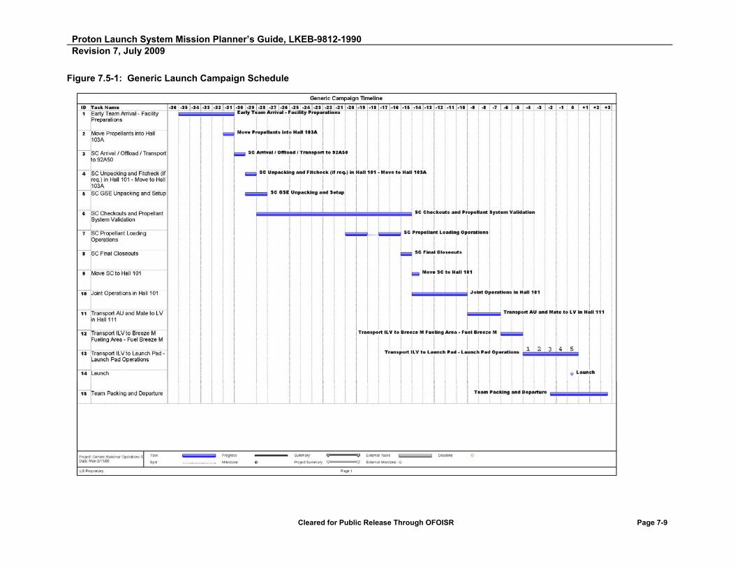
Proton Launch System Mission Planner’s Guide, LKEB-9812-1990 Revision 7, July 2009
Cleared for Public Release Through OFOISR Page 7-9
Figure 7.5-1: Generic Launch Campaign Schedule

Proton Launch System Mission Planner’s Guide, LKEB-9812-1990 Revision 7, July 2009
Cleared for Public Release Through OFOISR Page 7-10
7.5.2 SC Preparations Through Arrival
Prior to campaign start, SC propellants are shipped by rail from St. Petersburg to the Baikonur Cosmodrome. They can be stored in the same temperature-controlled railcars used for transport from St. Petersburg until required for fueling. The propellant containers are transferred to a storage/conditioning room for temperature stabilization prior to SC arrival in Hall 103A.
In advance of SC arrival, the payload processing facilities undergo facility activation and certification. Building 92A-50 is verified to meet environmental control and cleanliness requirements, in addition to commodities and power support requirements, usually three or four days prior to the SC arrival date.
The SC and its GSE arrive at Yubileiny Airfield via a SC Customer-chartered aircraft, where they are loaded onto railcars and trucks. These operations are supported by KhSC-supplied mobile cranes, K-loader, and forklifts, as required. After the SC container is placed on a railcar, it may be connected to a thermal control railcar via two air duct flanges (inlet and outlet air flow) to provide thermal conditioning during transport. Some SC containers are completely self-contained thermally and environmentally and do not require this support option. The thermal car also provides a dynamic load monitoring system. SC Customer personnel effects may be transported directly to the hotel by truck.
7.5.3 Area 92 (Building 92A-50) - SC Testing, Fueling and AU Integration
In this processing scenario, the SC and its GSE are transported by rail approximately 40 km to Building 92A-50, where external cleaning of the SC container is performed in Hall 102. Initial cleaning is conducted while in Hall 102, and final cleaning is performed after the move into Hall 101. Hall 101 is an ISO Class 8 cleanroom, and the SC container cover may be removed here or in Hall 103A as required by the unique mission-specific SC processing flow.
A typical flow is as follows:
a) Move the SC container into Hall 101 on railcar.
b) Remove container from the railcar and place on the floor in Hall 101.
c) Verify environment is within specification.
d) Remove the container lid.
e) Remove the SC from the container.
f) Place the SC on the transporter.
g) Move SC on transporter into Hall 103A for processing.

Proton Launch System Mission Planner’s Guide, LKEB-9812-1990 Revision 7, July 2009
Cleared for Public Release Through OFOISR Page 7-11
The SC container may be stored in Hall 101. Electrical test equipment is brought into the control room by means of an external door, which opens directly into the control room loading area. This is a small buffer zone between two sets of double doors.
After container removal, SC electrical testing, pneumatic testing, and propellant fueling occur in Hall 103A. Pass-throughs from the control room are available for cabling. These cable feeds are verified to be leak-tight prior to propellant operations. The 380 V/220 V/50 Hz and 208 V/120 V/60 Hz power source is provided by an UPS. Typically, the UPS is activated three or four days prior to SC arrival and not deactivated until launch and all parties agree that no further requirement for it exists. A portable blast shield is available for high-pressure tests.
For propellant operations, the facility is configured with liquid waste aspirators, passive vent scrubbers, and a vapor detection system, which alarms locally in the control room and at the Security Command Post. Breathing air is supplied by a single source, which is sampled prior to operations. GN2, water, and shop air are provided on demand. A fire suppression system, which will arm but not release on alarm, is also active in Hall 103A. The command to activate the suppression system deluge is made in the control room, and is not an automatic function of the alarm system. Liquid Nitrogen (LN2) is available with 24-hour call-up.
The loaded SC is transported back to Hall 101 using the transport dolly. The SC is lifted from the transporter and mated to the SC adapter using the 10-MT bridge crane. The adapter clampband is installed and tensioned. The SC/adapter unit is then lifted and mated to the Breeze M, which has been previously installed in the integration stand. Incremental electrical continuity tests are performed at each phase, with the final check being an end-to-end test with the SC mated to the Breeze M.
After SC integration, final closeout operations and photographs are performed. The combined Breeze M/SC is rotated to the horizontal position on the integration stand. After the upper fairing half is emplaced, an RF GO/NO-GO test is performed to ensure that the SC link has not been disturbed and that the RF window is transparent to RF. This is performed as soon as the fairing half is mechanically emplaced and before continuation of encapsulation sealing operations. If any anomaly is found, the fairing may be removed relatively easily at this point. After determining a good RF signal, encapsulation is completed.
After encapsulation and required RF testing, the integrated AU is placed on a railcar for transport to Hall 111 for integration with the Proton LV.

Proton Launch System Mission Planner’s Guide, LKEB-9812-1990 Revision 7, July 2009
Cleared for Public Release Through OFOISR Page 7-12
7.6 LV INTEGRATION THROUGH LAUNCH PAD OPERATIONS
The AU is transported to Hall 111 of Building 92A-50 for integration with the Proton M LV, where it is uncoupled from the thermal conditioning car and loaded onto the integration dollies. The AU is brought horizontally to the docking plane of the assembled Proton LV third stage by the integration dollies. An end-to-end electrical check is performed on the SC/LV umbilical cables. A thermal blanket is installed over the fairing to protect the payload from temperature extremes during periods when there is no active thermal control. The Integrated Launch Vehicle (ILV) is then transferred to the transporter-erector. A typical launch flow requires three to four days of integration hall activities. Integration hall operations are based on the LV pre-launch schedule.
The ILV is transported to the Breeze M fueling station for loading of the low-pressure MMH and N2O4 Breeze M propellant tanks on its way to Pads 24 or 39 for launch.
The first of two State Commission Meetings is held on ~ Day L-6, prior to vehicle roll-out to the pad, to ensure all agencies are ready for pad roll-out. All agencies, including the SC manufacturer acting in support of the Customer, will be called upon to provide a launch readiness statement.
7.7 LAUNCH PAD OPERATIONS
The ILV is transported to the launch pad and erected in one piece at Day L-4 using the LV transporter. From Day L-4 and on, the launch schedule is driven by Roscosmos overall countdown schedule. Coordination of SC-related pad activities is performed through the 7/701 Script (see Table 7-1 of the PLCG for an example). The 7/701 Script is generated by KhSC with SCC/Customer input and should include all pad access requirements and requirements for RF radiation and commanding the SC. Operator “7” is the KhSC Program Director, while Operator “701” is the SC point of contact. The following pad activity information is required from the SC/Customer: RF radiation, battery charging, SC commanding, and pad access. Note that ILS functions, such as scheduling of pad access, will also be coordinated through this script. Figure 7.7-1 provides a generic detailed on-pad operations flow.

Proton Launch System Mission Planner’s Guide, LKEB-9812-1990 Revision 7, July 2009
Cleared for Public Release Through OFOISR Page 7-13
Active commanding of the SC is prohibited during critical LV processing functions. Starting at Day L-5 and every day thereafter, KhSC identifies the RF silence and no-command times. The on-pad operations flow schedule is updated to incorporate these changes and active commanding of the SC is prohibited during these times.
The following items represent typical SC inhibits to RF radiation at the pad:
1. Personnel in vicinity of antenna/couplers
2. KhSC interface command/telemetry and calibration with LV
3. Roscosmos testing (usually a tracking facility or radar)
4. KhSC fueling operations
5. Others as specified by KhSC or Roscosmos
The SC Customer participates in a launch countdown rehearsal on Day L-2 on pad. This countdown rehearsal is supported by a full LV launch crew countdown and requires the SC Customer to indicate SC readiness to go at the required time. The rehearsal also includes a planned abort. SC full fidelity countdown rehearsal is not required for this exercise, simply the operation of the readiness switch at the planned time in accordance with the 7/701 Script.
The second State Commission Meeting is held at T-8 hours to ensure all agencies are GO for launch prior to propellant load of the LV. At T-8 hours, the launch pad is cleared of all non-essential personnel, and at T-6 hours, propellant load commences. At T-2.5 hours, the pad is open for final closeouts and service tower removal. At T-2 hours, all personnel should be in their final positions for launch (i.e., Bunker, Control Room, Viewing Area, and Communications Center). Note that personnel in the Bunker and the Communications Center should be limited to essential personnel only. All personnel must be cleared from the hotel areas for launches from Pad 24.
The SC Customer participates in the final countdown launch day activities including sending a SC readiness to launch signal at T-10 minutes, as noted in the countdown organization discussion.
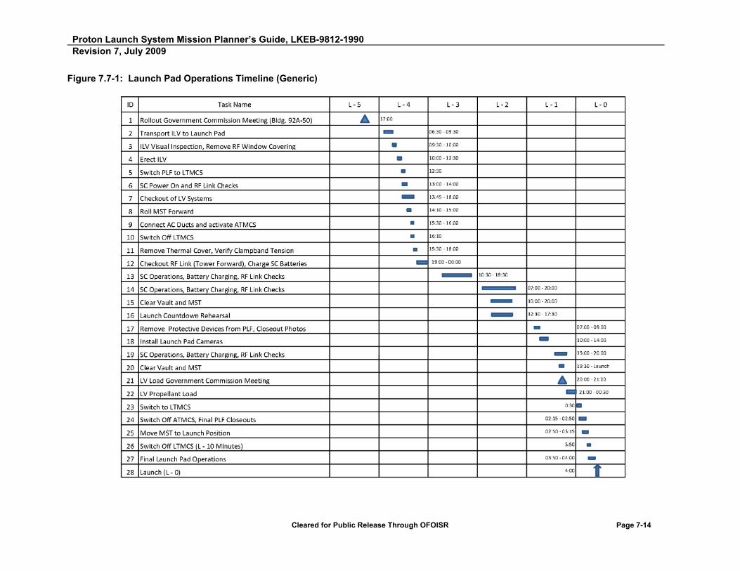
Proton Launch System Mission Planner’s Guide, LKEB-9812-1990 Revision 7, July 2009
Cleared for Public Release Through OFOISR Page 7-14
Figure 7.7-1: Launch Pad Operations Timeline (Generic)
Proton Launch System Mission Planner’s Guide
APPENDIX A
Proton Launch System Description and History

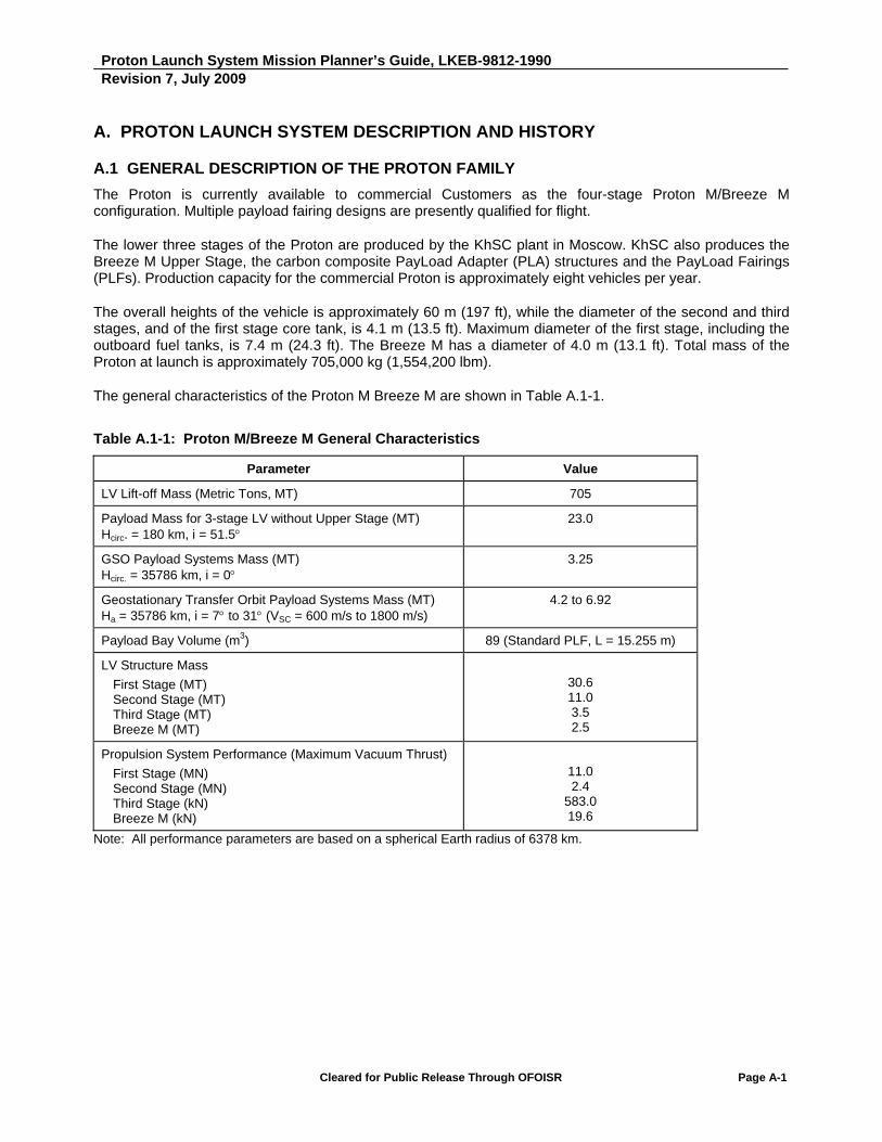
Proton Launch System Mission Planner’s Guide, LKEB-9812-1990 Revision 7, July 2009
Cleared for Public Release Through OFOISR Page A-1
A. PROTON LAUNCH SYSTEM DESCRIPTION AND HISTORY
A.1 GENERAL DESCRIPTION OF THE PROTON FAMILY
The Proton is currently available to commercial Customers as the four-stage Proton M/Breeze M configuration. Multiple payload fairing designs are presently qualified for flight.
The lower three stages of the Proton are produced by the KhSC plant in Moscow. KhSC also produces the Breeze M Upper Stage, the carbon composite PayLoad Adapter (PLA) structures and the PayLoad Fairings (PLFs). Production capacity for the commercial Proton is approximately eight vehicles per year.
The overall heights of the vehicle is approximately 60 m (197 ft), while the diameter of the second and third stages, and of the first stage core tank, is 4.1 m (13.5 ft). Maximum diameter of the first stage, including the outboard fuel tanks, is 7.4 m (24.3 ft). The Breeze M has a diameter of 4.0 m (13.1 ft). Total mass of the Proton at launch is approximately 705,000 kg (1,554,200 lbm).
The general characteristics of the Proton M Breeze M are shown in Table A.1-1.
Table A.1-1: Proton M/Breeze M General Characteristics
Parameter Value
LV Lift-off Mass (Metric Tons, MT) 705
Payload Mass for 3-stage LV without Upper Stage (MT) Hcirc. = 180 km, i = 51.5
23.0
GSO Payload Systems Mass (MT) Hcirc. = 35786 km, i = 0
3.25
Geostationary Transfer Orbit Payload Systems Mass (MT) Ha = 35786 km, i = 7 to 31 (VSC = 600 m/s to 1800 m/s)
4.2 to 6.92
Payload Bay Volume (m3) 89 (Standard PLF, L = 15.255 m)
LV Structure Mass
First Stage (MT) Second Stage (MT) Third Stage (MT) Breeze M (MT)
30.6 11.0 3.5 2.5
Propulsion System Performance (Maximum Vacuum Thrust)
First Stage (MN) Second Stage (MN) Third Stage (kN) Breeze M (kN)
11.0 2.4
583.0 19.6
Note: All performance parameters are based on a spherical Earth radius of 6378 km.
Proton Launch System Mission Planner’s Guide, LKEB-9812-1990 Revision 7, July 2009
Cleared for Public Release Through OFOISR Page A-2
A.2 PROTON M LV
An isometric view of the Proton three-stage booster with Breeze M Upper Stage showing the relationships among the major hardware elements is provided in Figure A.2-1. All three LV stages (and the Breeze M) use nitrogen tetroxide (N2O4) and unsymmetrical dimethylhydrazine (UDMH) as propellants.
A.2.1 Proton First Stage
The Proton M first stage consists of a central tank containing the oxidizer, surrounded by six outboard fuel tanks. Although these fuel tanks give the appearance of being strap-on boosters, they do not separate from the core tank during first stage flight. Each fuel tank also carries one of the six RD-276 engines that provide first stage power. Total first stage sea-level thrust is approximately 10.0 MN (2.25 x 10⁶ lbf) with a vacuum-rated thrust level of 11.0 MN (2.47 x 10⁶ lbf). Total first stage dry mass is approximately 30,600 kg (67,460 lbm); total first stage propellant load is approximately 428,300 kg (944,240 lbm).
The RD-276 engines now used on all Proton first stages are up-rated from the RD-275 design. Lift-off thrust on the engines of the first stage of Proton M has been increased by 5%, or 12% above the original RD-253 engine design. This enhancement was accomplished primarily through a minor modification to the propellant flow control valves. This modification first flew in July 2007. Engines incorporating this change have undergone extensive additional qualification firings since then, in order to approve them for use in standard production vehicles. As of 31 July 2009, a total of six Proton M LVs have flown with the RD-276 engine using the 112% thrust modification. Other than the changes to the propellant flow control valves, pressure feedback sensor and gas generator, the engines on the first stage of the Proton M LV are unchanged in their design and manufacture since 1965.
The propellant feed systems of the first, second and third stages of the Proton M have been simplified and redesigned in order to reduce propellant residuals in these stages by 50%, and a propellant purge system has been added to dump all residuals from the spent first stage before it returns to the earth's surface.
While a reduction in unusable propellants results in a performance gain, the primary rationale for the increased utilization of propellants is to minimize the environmental effects of the impact of the first and second stages in the downrange land-based hardware drop zones.

Proton Launch System Mission Planner’s Guide, LKEB-9812-1990 Revision 7, July 2009
Cleared for Public Release Through OFOISR Page A-3
A.2.2 Proton Second Stage
The second stage, of conventional cylindrical design, is powered by three RD-0210 engines and one RD-0211 engine, developing a total vacuum thrust of 2.4 MN, or 5.4 x 10⁵ lbf. The RD-0211 engine differs from the RD-0210 engine in that it accommodates a gas generator heat exchanger to supply pressurant gas to the fuel and oxidizer tanks. Total second stage dry mass is approximately 11,000 kg (24,250 lbm). Total second stage propellant load is approximately 157,300 kg (346,800 lbm).
A.2.3 Proton Third Stage
The third stage is equipped with one RD-0213 main engine (a non-gimbaled version of the RD-0210), developing 583 kN (1.3 x 10⁵ lbf) thrust, and one RD-0214 control engine with four gimbaled nozzles, developing 31 kN (7.0 x 10³ lbf) thrust. Total third stage dry mass is approximately 3,500 kg (7,700 lbm). Total third stage propellant load is approximately 46,562 kg (102,650 lbm).
A.2.4 Proton Flight Control System
Guidance, navigation, and control of the Proton M during operation of the first three stages is carried out by a single-fault-tolerant majority-voting closed-loop digital avionics system mounted in the Proton's third stage. This self-contained inertial control system uses a precision three-axis gyro-stabilizer and an on-board digital computer. This system also provides for flight termination in the event of a major malfunction during ascent.
The Proton M’s digital flight control system is based on modern avionics technology. The new system allows for simplified control algorithm loading and test. It also enables greater ascent program design flexibility with respect to vehicle pitch profile and other parameters.

Proton Launch System Mission Planner’s Guide, LKEB-9812-1990 Revision 7, July 2009
Cleared for Public Release Through OFOISR Page A-4
A.3 BREEZE M UPPER STAGE
The Breeze M Upper Stage, which is derived from the Breeze K Upper Stage flown on the Rokot, offers substantially improved payload performance and operational capabilities over the Block DM flown on the Proton K. The Breeze M program was initiated in 1994 by the Khrunichev Space Center and the Russian government. An isometric view of the Proton M/Breeze M is shown in Figure A.3-1. The layout and dimensions of the integrated Proton M/Breeze M space rocket are shown in Figure A.3-2.
The Breeze M is 2.65 meters in height and 4.0 meters in diameter, with a dry mass of 2,500 kg and a total propellant mass of 19,800 kg. It consists of the following three main elements:
1) A core section (central block) derived from the original Breeze K that accommodates a set of propellant tanks, the propulsion system, and the avionics equipment bay. Total propellant capacity of the core is 5.2 metric tons.
2) A toroidal Auxiliary Propellant Tank (APT) that surrounds the core section, and which is jettisoned in flight following depletion of its 14.6 metric tons of propellant. The application of the APT substantially improves the performance of the Breeze M stage.
3) A lower spacer used for mounting the Breeze M (at 4100 mm diameter) and payload fairing (at 4350 mm diameter) on the LV third stage; the spacer is jettisoned together with the LV third stage rocket.
Figures A.3-1 and A.3-2 illustrate the layout and dimensions of the Breeze M. Further details of the main elements of the Breeze M are given below.
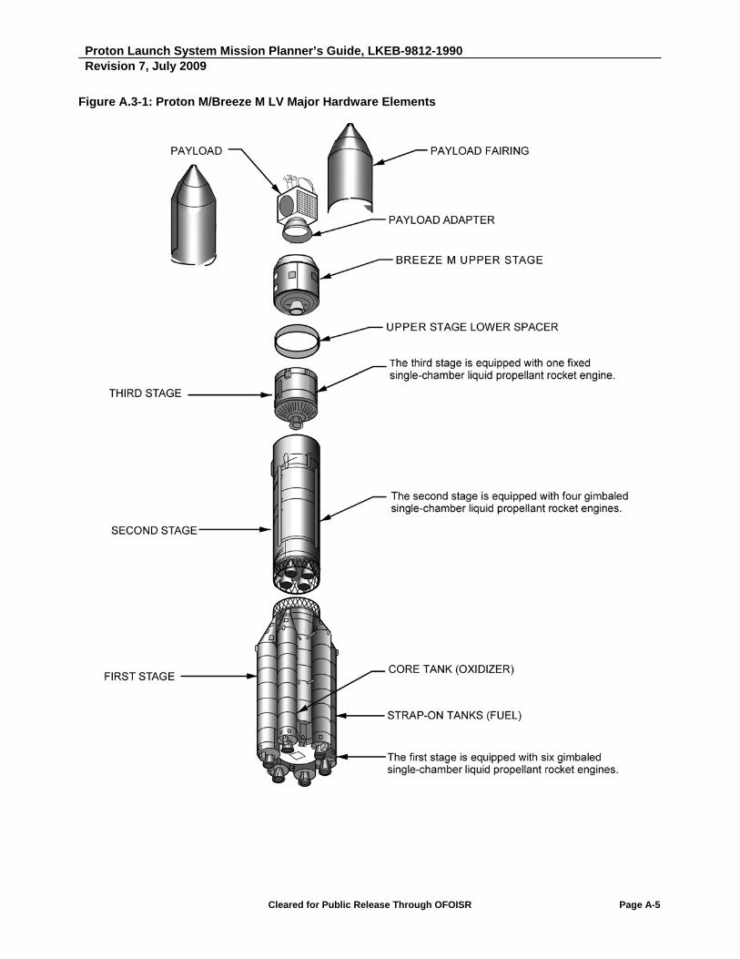
Proton Launch System Mission Planner’s Guide, LKEB-9812-1990 Revision 7, July 2009
Cleared for Public Release Through OFOISR Page A-5
Figure A.3-1: Proton M/Breeze M LV Major Hardware Elements

Proton Launch System Mission Planner’s Guide, LKEB-9812-1990 Revision 7, July 2009
Cleared for Public Release Through OFOISR Page A-6
Figure A.3-2: General Layout of Breeze M with Auxiliary Propellant Tank
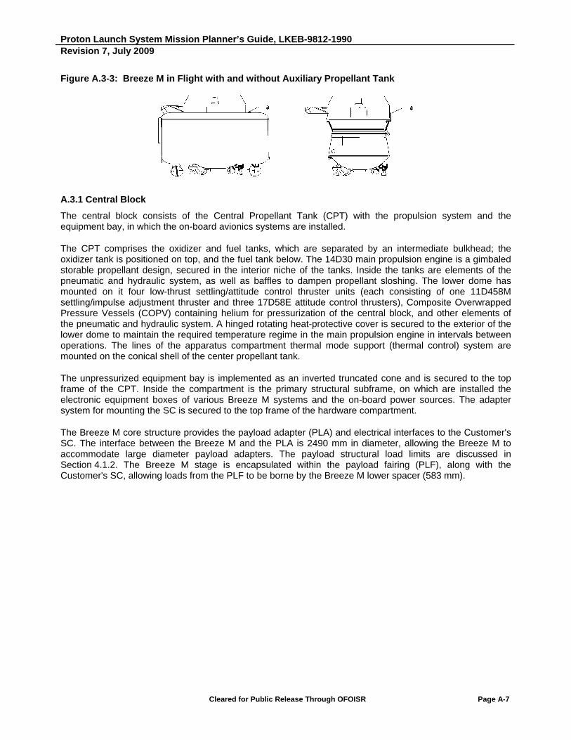
Proton Launch System Mission Planner’s Guide, LKEB-9812-1990 Revision 7, July 2009
Cleared for Public Release Through OFOISR Page A-7
Figure A.3-3: Breeze M in Flight with and without Auxiliary Propellant Tank
A.3.1 Central Block
The central block consists of the Central Propellant Tank (CPT) with the propulsion system and the equipment bay, in which the on-board avionics systems are installed.
The CPT comprises the oxidizer and fuel tanks, which are separated by an intermediate bulkhead; the oxidizer tank is positioned on top, and the fuel tank below. The 14D30 main propulsion engine is a gimbaled storable propellant design, secured in the interior niche of the tanks. Inside the tanks are elements of the pneumatic and hydraulic system, as well as baffles to dampen propellant sloshing. The lower dome has mounted on it four low-thrust settling/attitude control thruster units (each consisting of one 11D458M settling/impulse adjustment thruster and three 17D58E attitude control thrusters), Composite Overwrapped Pressure Vessels (COPV) containing helium for pressurization of the central block, and other elements of the pneumatic and hydraulic system. A hinged rotating heat-protective cover is secured to the exterior of the lower dome to maintain the required temperature regime in the main propulsion engine in intervals between operations. The lines of the apparatus compartment thermal mode support (thermal control) system are mounted on the conical shell of the center propellant tank.
The unpressurized equipment bay is implemented as an inverted truncated cone and is secured to the top frame of the CPT. Inside the compartment is the primary structural subframe, on which are installed the electronic equipment boxes of various Breeze M systems and the on-board power sources. The adapter system for mounting the SC is secured to the top frame of the hardware compartment.
The Breeze M core structure provides the payload adapter (PLA) and electrical interfaces to the Customer's SC. The interface between the Breeze M and the PLA is 2490 mm in diameter, allowing the Breeze M to accommodate large diameter payload adapters. The payload structural load limits are discussed in Section 4.1.2. The Breeze M stage is encapsulated within the payload fairing (PLF), along with the Customer's SC, allowing loads from the PLF to be borne by the Breeze M lower spacer (583 mm).

Proton Launch System Mission Planner’s Guide, LKEB-9812-1990 Revision 7, July 2009
Cleared for Public Release Through OFOISR Page A-8
A.3.2 Auxiliary Propellant Tank
The Auxiliary Propellant Tank (APT) is positioned around the central block and is implemented as a toroidal compartment with cylindrical shells and an intermediate bulkhead that divides the compartment into the oxidizer tank (top) and fuel tank (bottom). Loads are conveyed from the SC and central block through the load-bearing cone inside the oxidizer tank and through the outer cylindrical shell of the fuel tank. The cone has been optimized to increase the load bearing capability and reduce quasi-static loads on the spacecraft. Loads are then transferred to the bottom spacer of the Breeze M. Inside the tanks are elements of the pneumatic and hydraulic system, as well as baffles to damp propellant sloshing. On the exterior of the lower dome of the APT are elements of the pneumatic and hydraulic system, including bottles for pressurization of the APT, units of automatic pneumatic and hydraulic equipment, and boards with electrical connectors.
When the APT is jettisoned, the pyrotechnic locks that connect the tank to the central block are fired, and electrical and hydraulic connections are broken. Then a set of spring pushers are actuated, and the APT is separated from the central block by means of two guides on the APT and roller supports on the central block.
A.3.3 Propulsion System
The Breeze M uses nitrogen tetroxide (N2O4) and unsymmetrical-dimethylhydrazine (UDMH) as propellants. Propulsion for the Breeze M consists of one pump-fed, gimbaled 14D30 main engine developing 19.62 kN (4411 lbf) thrust, four 11D458M settling/impulse adjustment thrusters with 392 N (88 lbf) thrust for making fine trim maneuver corrections to the main engine impulse, and twelve 17D58E attitude control thrusters with 13.3 N (3.0 lbf) thrust each. The main engine can fire up to eight times per mission, and is equipped with a backup restart system that can fire the engine in the event of a primary ignition sequence failure. The main engine can be commanded to shut down either upon achieving a desired state vector or propellant depletion.
The propulsion system of the Breeze M is derived from, and has a high degree of commonality with, previous flight systems. During two flights of the Phobos space probes in 1988 and three flights of the Breeze K on the Rokot in 1990, 1991, and 1994 the main engine demonstrated up to five restarts in flight. Following minor modifications to adapt the engine for the Breeze M, 11 main engines were ground tested — some up to 6,000 seconds total burn duration. The Breeze M attitude control thrusters were previously used on the Kvant, Kristall, Spektr, and Priroda modules of the MIR space station, and are used on the Russian FGB Zarya and Service Module Zvezda components of the International Space Station. As of 31 July 2009, the Breeze M propulsion system has operated successfully on 30 flights, performing multiple burns on each mission.

Proton Launch System Mission Planner’s Guide, LKEB-9812-1990 Revision 7, July 2009
Cleared for Public Release Through OFOISR Page A-9
The propulsion system of the Breeze M performs the following actions:
Provides thrust pulses specified in the flight program to trim velocity.
Controls the angular motion of the stage.
Performs repeated firings of the main propulsion engine under weightless conditions.
Supplies propellant from the tanks to the engines.
Pressurizes the propellant tanks.
Characteristics of the engines used in the Breeze M propulsion system are provided in Table A.3.3-1.
Table A.3.3-1: Basic Characteristics of the Breeze M Propulsion System
Main Propulsion Engine
Designation 14D30
Vacuum Thrust 19.62 kN
Number of Firings Per Flight Up to 8
Thrusters
Vernier Engines:
Designation 11D458M
Number of 4
Vacuum Thrust 392 N
Attitude and Stabilization Engines:
Designation 17D58E
Number of 12
Vacuum Thrust 13.3 N
A.3.4 Control System and Telemetry System
The control system of the Breeze M includes a three-channel voting on-board digital computer, precision three-axis gyro stabilized platform, and navigation systems. The following functions are performed by the control system.
- Inertial navigation
- Terminal guidance
- Attitude control
- Control of the operating modes of the propulsion system and other Breeze M on-board systems
- Information exchange with the SC and LV control systems
- Control of separation of the APT and SC
- Electrical power supply to Breeze M on-board equipment

Proton Launch System Mission Planner’s Guide, LKEB-9812-1990 Revision 7, July 2009
Cleared for Public Release Through OFOISR Page A-10
The Breeze M can perform preprogrammed maneuvers about all axes during parking, intermediate, and transfer orbit coasts. The Breeze M is normally three-axis stabilized during coast. During powered flight, the Breeze M attitude is determined by navigational algorithms of the flight control system. The Breeze M attitude can be controlled in coasting mode to an angular pointing accuracy of 10.0 degrees in coarse pointing mode and 1.0 degree in fine pointing mode. When the Breeze M is coasting in rotation mode, angular velocity accuracy is 0.5 deg/s.
Thermal control of the SC can be provided through the use of a control maneuver, in which the Breeze M and SC rotate about the longitudinal X or transverse Z axis of the Breeze M. Maneuvers of 180 degrees performed in one direction (lasting no more than 600 seconds about the longitudinal axis) or 900 seconds about the transverse axis, can be used. Alternatively, continuous rotation of the Breeze M is possible about the longitudinal axis, with an angular velocity of up to 3 deg/s.
The possibility of performing these maneuvers, as well as continuous rotation, will be defined by the SC sun exposure and launch window requirements.
Breeze M can perform separation of a Customer's SC in any one of three modes, depending upon SC separation requirements and launch window:
1) Three-axis stabilization mode, during which the separation-induced SC angular rates in relation to any of the three coordinate system axes will not exceed 1.0 deg/s, and the spatial attitude error in relation to the inertial coordinate system will not exceed 5 degrees, or
2) Longitudinal spin-up mode, during which the Breeze M can achieve a maximum angular rate of 6.0 deg/s about its longitudinal axis, and the SC spin axis deviation from the Breeze M longitudinal axis after separation will not exceed 5 degrees, and will be determined by the SC characteristics and Customer requirements for SC separation dynamics, or
3) Transverse spin-up mode, in which the SC is spun around the transverse axis either by use of unsymmetrical springs or by rotation of the Breeze M at an angular velocity of up to 2.0 deg/s.
The Breeze M telemetry system (on-board measuring complex) performs the following functions:
- Collection of data on the state of design elements and on the operation of the Breeze M and SC systems and units (according to an agreed upon list) throughout all stages of flight and during pre-launch preparations.
- Transmission of telemetry data to ground measuring stations.
All equipment in the on-board measuring complex was especially developed for the Breeze M.

Proton Launch System Mission Planner’s Guide, LKEB-9812-1990 Revision 7, July 2009
Cleared for Public Release Through OFOISR Page A-11
The telemetry data acquisition system operates in direct transmission mode, memory mode, playback mode, or the combined modes, executing programs that differ in telemetered parameters and polling frequencies.
Radio frequency measurements are recorded by means of the Breeze M telemetry system. The Breeze M can make use of both the GLONASS and GPS satellite navigation systems.
The parameters monitored by the telemetry system are summarized below:
- During processing, launch and flight, the operation of Breeze M systems and components is under constant monitoring by the telemetry measurement system and the control system.
- The load on and state of the Breeze M structure are monitored for 120 parameters.
- The operation of the propulsion unit is monitored for 83 parameters.
- The operation of the thermal mode support system is monitored for 20 parameters.
- The operation of the control system is monitored for more than 200 parameters.
The data obtained, in the form of files of analog and digital parameters, are sent to ground measuring stations and put through comprehensive analysis.
A.3.5 Thermal Control System
The thermal control system (thermal mode support system) is a complex of means of active and passive temperature regulation that includes the following elements:
- The thermal control system, which maintains the specific temperature of the Breeze M elements and radiates excess heat into space by means of the control system. The thermal control system consists of a hydraulic circuit, which includes a radiative heat exchanger, an electrical pump unit, a switch, cold plates (heat sinks), heat pipes of the instrument subframe, and the coils of the instrument subframe and propellant compartment.
- Means of passive temperature regulation, which handle external heat exchange of the Breeze M within the range determined by heat losses and heat influxes, as well as the thermal conditions of units by means of temperature-regulating coatings, thermostats, thermal resistances, and vacuum thermal insulation (Multi-Layer Insulation, MLI).

Proton Launch System Mission Planner’s Guide, LKEB-9812-1990 Revision 7, July 2009
Cleared for Public Release Through OFOISR Page A-12
A.4 PROTON FLIGHT HISTORY SUMMARY
The total number of operational missions flown by Proton three and four-stage configurations since the first Proton launch is 323 as of 31 July 2009. If development flights are included, then the Proton has flown in excess of 340 times. It has launched the Ekran, Raduga, and Gorizont series of geostationary communications satellites (which provided telephone, telegraph, and television service within Russia and between member states of the Intersputnik Organization), as well as the Zond, Luna, Venera, Mars, Vega, and Phobos inter-planetary exploration SC. All Russian unmanned lunar landing missions were flown by Proton. The Proton has also launched the entire constellation of Glonass position location satellites and has carried the Salyut series space stations and the Mir space station modules. Proton launched the Zarya and Zvezda modules, which comprised the first two elements of the International Space Station. All Russian geostationary and interplanetary missions are launched on Proton. Approximately 90% of all Proton launches have been of a four-stage version.
As of 31 July 2009, ILS has launched 52 commercial SC on Proton.
The Proton LV is one of the most reliable commercial launch vehicles available today. Summary launch data by year are shown in Table A.4-2.

Proton Launch System Mission Planner’s Guide, LKEB-9812-1990 Revision 7, July 2009
Cleared for Public Release Through OFOISR Page A-13
Table A.4-1: Breeze M Flight History
Breeze M Flight
Number
Launch Date
(GMT)
Mission Name
Mission Type
Payload Separated Mass (kg)
Launch Pad
Approximate Mission Duration
(hrs)
Number of Breeze M
Burns
Hardware - Main Stages, Adapter, PLF
Results
1 5 July 1999
Raduga GSO 1932 24 - - LV: Proton K PLF: 14C75 Adapter H = 465 mm (metal)
Proton second stage failure; no trial
2 6 June 2000
Gorizont GSO 2158 24 9.2 4 LV: Proton K PLF: 14C75 Adapter H = 465 mm (metal)
Successful
3 7 Apr 2001
Ekran M GSO 2005 24 6.8 3 LV: Proton M PLF: 14C75 Adapter H = 465 mm (metal)
Successful
4 30 Dec 2002
NIMIQ 2 GTO 3600 24 6.9 4 LV: Proton M PLF: MITS Adapter H = 1000 mm (carbon fiber)
Successful
5 7 Jun 2003
AMC-9 GTO 4100 39 8.9 5 LV: Proton K PLF: 14C75 Adapter H = 1000 mm (carbon fiber)
Successful
6 10 Dec 2003
GLONASS MEO 4110 (3 x 1370)
24 5.8 3 LV: Proton K PLF: 14C75 Adapter H = 465 mm (metal)
Successful
7 16 Mar 2004
W3A GTO 4200 24 9.2 5 LV: Proton M PLF: 14C75 Adapter H = 1000 mm (carbon fiber)
Successful
8 17 Jun 2004
Intelsat 10-02 GTO 5575 39 9.2 5 LV: Proton M PLF: PLF-BR-15255 Adapter H = 1000 mm (carbon fiber)
Successful
9 5 Aug 2004
Amazonas 1 GTO 4540 39 9.2 5 LV: Proton M PLF: PLF-BR-15255 Adapter H = 1000 mm (carbon fiber)
Successful
10 14 Oct 2004
AMC 15 GTO 4021 39 6.9 3 LV: Proton M PLF: PLF-BR-15255 Adapter H = 1000 mm (carbon fiber)
Successful
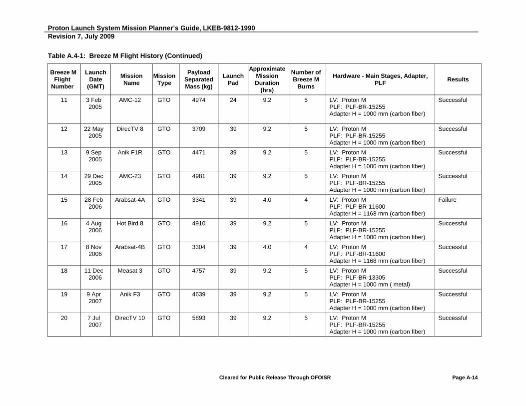
Proton Launch System Mission Planner’s Guide, LKEB-9812-1990 Revision 7, July 2009
Cleared for Public Release Through OFOISR Page A-14
Table A.4-1: Breeze M Flight History (Continued)
Breeze M Flight
Number
Launch Date
(GMT)
Mission Name
Mission Type
Payload Separated Mass (kg)
Launch Pad
Approximate Mission Duration
(hrs)
Number of Breeze M
Burns
Hardware - Main Stages, Adapter, PLF
Results
11 3 Feb 2005
AMC-12 GTO 4974 24 9.2 5 LV: Proton M PLF: PLF-BR-15255 Adapter H = 1000 mm (carbon fiber)
Successful
12 22 May 2005
DirecTV 8 GTO 3709 39 9.2 5 LV: Proton M PLF: PLF-BR-15255 Adapter H = 1000 mm (carbon fiber)
Successful
13 9 Sep 2005
Anik F1R GTO 4471 39 9.2 5 LV: Proton M PLF: PLF-BR-15255 Adapter H = 1000 mm (carbon fiber)
Successful
14 29 Dec 2005
AMC-23 GTO 4981 39 9.2 5 LV: Proton M PLF: PLF-BR-15255 Adapter H = 1000 mm (carbon fiber)
Successful
15 28 Feb 2006
Arabsat-4A GTO 3341 39 4.0 4 LV: Proton M PLF: PLF-BR-11600 Adapter H = 1168 mm (carbon fiber)
Failure
16 4 Aug 2006
Hot Bird 8 GTO 4910 39 9.2 5 LV: Proton M PLF: PLF-BR-15255 Adapter H = 1000 mm (carbon fiber)
Successful
17 8 Nov 2006
Arabsat-4B GTO 3304 39 4.0 4 LV: Proton M PLF: PLF-BR-11600 Adapter H = 1168 mm (carbon fiber)
Successful
18 11 Dec 2006
Measat 3 GTO 4757 39 9.2 5 LV: Proton M PLF: PLF-BR-13305 Adapter H = 1000 mm ( metal)
Successful
19 9 Apr 2007
Anik F3 GTO 4639 39 9.2 5 LV: Proton M PLF: PLF-BR-15255 Adapter H = 1000 mm (carbon fiber)
Successful
20 7 Jul 2007
DirecTV 10 GTO 5893 39 9.2 5 LV: Proton M PLF: PLF-BR-15255 Adapter H = 1000 mm (carbon fiber)
Successful
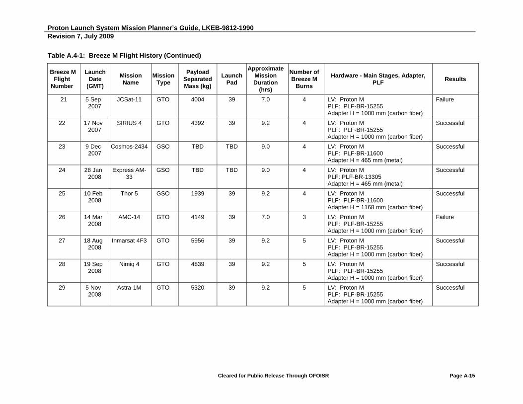
Proton Launch System Mission Planner’s Guide, LKEB-9812-1990 Revision 7, July 2009
Cleared for Public Release Through OFOISR Page A-15
Table A.4-1: Breeze M Flight History (Continued)
Breeze M Flight
Number
Launch Date
(GMT)
Mission Name
Mission Type
Payload Separated Mass (kg)
Launch Pad
Approximate Mission Duration
(hrs)
Number of Breeze M
Burns
Hardware - Main Stages, Adapter, PLF
Results
21 5 Sep 2007
JCSat-11 GTO 4004 39 7.0 4 LV: Proton M PLF: PLF-BR-15255 Adapter H = 1000 mm (carbon fiber)
Failure
22 17 Nov 2007
SIRIUS 4 GTO 4392 39 9.2 4 LV: Proton M PLF: PLF-BR-15255 Adapter H = 1000 mm (carbon fiber)
Successful
23 9 Dec 2007
Cosmos-2434 GSO TBD TBD 9.0 4 LV: Proton M PLF: PLF-BR-11600 Adapter H = 465 mm (metal)
Successful
24 28 Jan 2008
Express AM-33
GSO TBD TBD 9.0 4 LV: Proton M PLF: PLF-BR-13305 Adapter H = 465 mm (metal)
Successful
25 10 Feb 2008
Thor 5 GSO 1939 39 9.2 4 LV: Proton M PLF: PLF-BR-11600 Adapter H = 1168 mm (carbon fiber)
Successful
26 14 Mar 2008
AMC-14 GTO 4149 39 7.0 3 LV: Proton M PLF: PLF-BR-15255 Adapter H = 1000 mm (carbon fiber)
Failure
27 18 Aug 2008
Inmarsat 4F3 GTO 5956 39 9.2 5 LV: Proton M PLF: PLF-BR-15255 Adapter H = 1000 mm (carbon fiber)
Successful
28 19 Sep 2008
Nimiq 4 GTO 4839 39 9.2 5 LV: Proton M PLF: PLF-BR-15255 Adapter H = 1000 mm (carbon fiber)
Successful
29 5 Nov 2008
Astra-1M GTO 5320 39 9.2 5 LV: Proton M PLF: PLF-BR-15255 Adapter H = 1000 mm (carbon fiber)
Successful
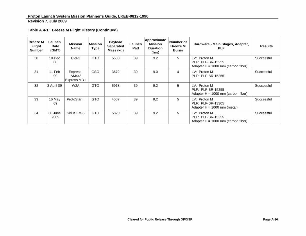
Proton Launch System Mission Planner’s Guide, LKEB-9812-1990 Revision 7, July 2009
Cleared for Public Release Through OFOISR Page A-16
Table A.4-1: Breeze M Flight History (Continued)
Breeze M Flight
Number
Launch Date
(GMT)
Mission Name
Mission Type
Payload Separated Mass (kg)
Launch Pad
Approximate Mission Duration
(hrs)
Number of Breeze M
Burns
Hardware - Main Stages, Adapter, PLF
Results
30 10 Dec 08
Ciel-2 GTO 5588 39 9.2 5 LV: Proton M PLF: PLF-BR-15255 Adapter H = 1000 mm (carbon fiber)
Successful
31 11 Feb 09
Express-AM44/
Express MD1
GSO 3672 39 9.0 4 LV: Proton M PLF: PLF-BR-15255
Successful
32 3 April 09 W2A GTO 5918 39 9.2 5 LV: Proton M PLF: PLF-BR-15255 Adapter H = 1000 mm (carbon fiber)
Successful
33 16 May 09
ProtoStar II GTO 4007 39 9,2 5 LV: Proton M PLF: PLF-BR-13305 Adapter H = 1000 mm (metal)
Successful
34 30 June 2009
Sirius FM-5 GTO 5820 39 9.2 5 LV: Proton M PLF: PLF-BR-15255 Adapter H = 1000 mm (carbon fiber)
Successful

Proton Launch System Mission Planner’s Guide, LKEB-9812-1990 Revision 7, July 2009
Cleared for Public Release Through OFOISR Page A-17
Table A.4-2: Proton Operational Launch Record Summary (1970 - 2009)
Year Number
of Launches
Number of Launches by Version
Total Launches on
Accrual Basis
Failures
4-Stage Version
3-Stage Version
Type of Vehicle Cause
(Details in Section A.6)
1970 6 5 1 6 1 Proton K Block DM a
1971 6 5 1 12
1972 2 1 1 14 1 Proton K b
1973 7 5 2 21
1974 6 4 2 27
1975 5 5 - 32 1 Proton K Block DM c
1976 5 3 2 37
1977 5 2 3 42 1 Proton K d
1978 8 7 1 50 3 Proton K Block DM e, f, g
1979 6 5 1 56
1980 5 5 - 61
1981 7 6 1 68
1982 10 9 1 78 2 Proton K Block DM h, i
1983 12 11 1 90
1984 13 13 - 103
1985 10 9 1 113
1986 9 7 2 122 1 Proton K j
1987 13 11 2 135 2 Proton K Block DM k, l
1988 13 13 - 148 2 Proton K Block DM m, n
1989 11 10 1 159
1990 11 10 1 170 1 Proton K Block DM o
1991 9 8 1 179
1992 8 8 - 187
1993 6 6 - 193 1 Proton K Block DM p
1994 13 13 - 206
1995 7 6 1 213
1996 8 7 1 221 2 Proton K Block DM q, r
1997 9 9 - 230 1 Proton K Block DM s
1998 7 6 1 237
1999 9 9 - 246 2 Proton K Block DM t, u
2000 14 13 1 260
2001 6 6 - 266
2002 9 9 - 275 1 Proton K Block DM v
2003 5 5 - 280
2004 7 7 - 288
2005 7 7 - 295
2006 6 6 - 301 1 Proton M/Breeze M w
2007 7 7 - 308 1 Proton M/Breeze M x
2008 8 10 - 318 1 Proton M/Breeze M y
2009 5 5 - 323 Note: As of 31 July 2009

Proton Launch System Mission Planner’s Guide, LKEB-9812-1990 Revision 7, July 2009
Cleared for Public Release Through OFOISR Page A-18
A.5 DETAILED PROTON FLIGHT HISTORY
The Proton launch history since 1970 is shown in Table A.5-1. The stated orbital parameters are approximate and included for information only.
Table A.5-1: Proton Operational Launch History
Date (GMT) Proton Variant
Payload Orbit Type Comments 4-stage 3-stage
1 6 Feb 1970 Cosmos Failed to orbit Command abort
2 18 Aug 1970 Experimental Ballistic Test
3 12 Sep 1970 Luna-16 Escape
4 20 Oct 1970 Zond-8 Escape
5 10 Nov 1970 Luna-17 Escape
6 2 Dec 1970 Cosmos-382 2464 km x 5189 km at 51.9 deg
7 19 Apr 1971 Salyut-1 200 km x 210 km at 51.6 deg
8 10 May 1971 Cosmos-419 145 km x 159 km at 51.5 deg
9 19 May 1971 Mars-2 Escape
10 28 May 1971 Mars-3 Escape
11 2 Sep 1971 Luna-18 Escape
12 28 Sep 1971 Luna-19 Escape
13 14 Feb 1972 Luna-20 Escape
14 29 Jul 1972 Salyut Failed to orbit
15 8 Jan 1973 Luna-21 Escape
16 3 Apr 1973 Salyut-2 207 km x 248 km at 51.6 deg
17 11 May 1973 Cosmos-557 214 km x 243 km at 51.6 deg
18 21 Jul 1973 Mars-4 Escape
19 25 Jul 1973 Mars-5 Escape
20 5 Aug 1973 Mars-6 Escape
21 9 Aug 1973 Mars-7 Escape
22 26 Mar 1974 Cosmos-637 LEO
23 29 May 1974 Luna-22 Escape
24 24 Jun 1974 Salyut-3 LEO
25 29 Jul 1974 Molniya-1S Elliptical orbit
26 28 Oct 1974 Luna-23 Escape
27 26 Dec 1974 Salyut-4 LEO
28 6 Jun 1975 Venera-9 Earth escape
29 14 Jun 1975 Venera-10 Earth escape
30 8 Oct 1975 Cosmos-775 LEO
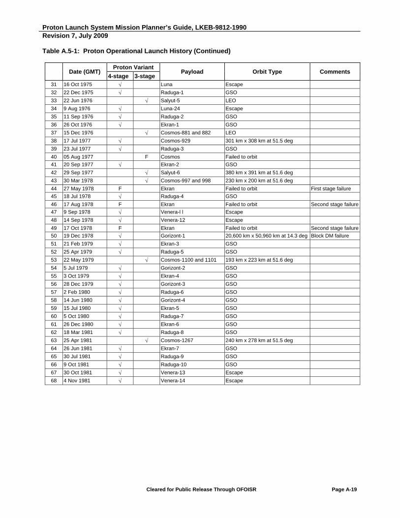
Proton Launch System Mission Planner’s Guide, LKEB-9812-1990 Revision 7, July 2009
Cleared for Public Release Through OFOISR Page A-19
Table A.5-1: Proton Operational Launch History (Continued)
Date (GMT) Proton Variant
Payload Orbit Type Comments 4-stage 3-stage
31 16 Oct 1975 Luna Escape
32 22 Dec 1975 Raduga-1 GSO
33 22 Jun 1976 Salyut-5 LEO
34 9 Aug 1976 Luna-24 Escape
35 11 Sep 1976 Raduga-2 GSO
36 26 Oct 1976 Ekran-1 GSO
37 15 Dec 1976 Cosmos-881 and 882 LEO
38 17 Jul 1977 Cosmos-929 301 km x 308 km at 51.5 deg
39 23 Jul 1977 Raduga-3 GSO
40 05 Aug 1977 F Cosmos Failed to orbit
41 20 Sep 1977 Ekran-2 GSO
42 29 Sep 1977 Salyut-6 380 km x 391 km at 51.6 deg
43 30 Mar 1978 Cosmos-997 and 998 230 km x 200 km at 51.6 deg
44 27 May 1978 F Ekran Failed to orbit First stage failure
45 18 Jul 1978 Raduga-4 GSO
46 17 Aug 1978 F Ekran Failed to orbit Second stage failure
47 9 Sep 1978 Venera-l l Escape
48 14 Sep 1978 Venera-12 Escape
49 17 Oct 1978 F Ekran Failed to orbit Second stage failure
50 19 Dec 1978 Gorizont-1 20,600 km x 50,960 km at 14.3 deg Block DM failure
51 21 Feb 1979 Ekran-3 GSO
52 25 Apr 1979 Raduga-5 GSO
53 22 May 1979 Cosmos-1100 and 1101 193 km x 223 km at 51.6 deg
54 5 Jul 1979 Gorizont-2 GSO
55 3 Oct 1979 Ekran-4 GSO
56 28 Dec 1979 Gorizont-3 GSO
57 2 Feb 1980 Raduga-6 GSO
58 14 Jun 1980 Gorizont-4 GSO
59 15 Jul 1980 Ekran-5 GSO
60 5 Oct 1980 Raduga-7 GSO
61 26 Dec 1980 Ekran-6 GSO
62 18 Mar 1981 Raduga-8 GSO
63 25 Apr 1981 Cosmos-1267 240 km x 278 km at 51.5 deg
64 26 Jun 1981 Ekran-7 GSO
65 30 Jul 1981 Raduga-9 GSO
66 9 Oct 1981 Raduga-10 GSO
67 30 Oct 1981 Venera-13 Escape
68 4 Nov 1981 Venera-14 Escape

Proton Launch System Mission Planner’s Guide, LKEB-9812-1990 Revision 7, July 2009
Cleared for Public Release Through OFOISR Page A-20
Table A.5-1: Proton Operational Launch History (Continued)
Date (GMT) Proton Variant Payload Orbit Type Comments
4-stage 3-stage 69 5 Feb 1982 Ekran-8 GSO
70 15 Mar 1982 Gorizont-5 GSO
71 19 Apr 1982 Salyut-7 473 km x 474 km at 51.6 deg
72 17 May 1982 Cosmos-1366 GSO
73 23 Jul 1982 F Ekran Failed to orbit First stage failure
74 16 Sep 1982 Ekran-9 GSO
75 12 Oct 1982 Cosmos-1413 and 1415 19,000 km x 19,000 km at 64.7 deg
76 20 Oct 1982 Gorizont-6 GSO
77 26 Nov 1982 Raduga-11 GSO
78 24 Dec 1982 F Raduga Failed to orbit Second stage failure
79 2 Mar 1983 Cosmos-1443 324 km x 327 km at 51.6 deg
80 12 Mar 1983 Ekran-10 GSO
81 23 Mar 1983 Astron-1 1,950 km x 201,100 km at 51.09 deg
82 8 Apr 1983 Raduga-12 GSO
83 2 Jun 1983 Venera-15 Escape
84 6 Jun 1983 Venera-16 Escape
85 1 Jul 1983 Gorizont-7 GSO
86 10 Aug 1983 Cosmos-1490 and 1492 19,000 km x 19,000 km at 64.8 deg
87 25 Aug 1983 Raduga-13 GSO
88 29 Sep 1983 Ekran-II GSO
89 30 Nov 1983 Gorizont-8 GSO
90 29 Dec 1983 Cosmos-1519 and 1521 19,000 km x 19,000 km at 64.8 deg
91 15 Feb 1984 Raduga-14 GSO
92 2 Mar 1984 Cosmos-1540 GSO
93 16 Mar 1984 Ekran-12 GSO
94 29 Mar 1984 Cosmos-1546 GSO
95 22 Apr 1984 Gorizont-9 GSO
96 19 May 1984 Cosmos-1554 and 1556 19,000 km x 19,000 km at 64.8
97 22 Jun 1984 Raduga-15 GSO
98 1 Aug 1984 Gorizont-10 GSO
99 24 Aug 1984 Ekran-13 GSO
100 4 Sep 1984 Cosmos-1593 and 1595 19,000 km x 19,000 km at 64.8
101 28 Sep 1984 Cosmos-1603 836 km x 864 km at 71 deg
102 15 Dec 1984 Vega-1 Escape
103 21 Dec 1984 Vega-2 Escape
104 18 Jan 1985 Gorizont-ll GSO
105 21 Feb 1985 Cosmos-1629 GSO
106 22 Mar 1985 Ekran-14 GSO
107 17 May 1985 Cosmos-1650 and 1652 19,000 km x 19,000 km at 64.8
108 30 May 1985 Cosmos-1656 800 km x 860 km at 71.1 deg
109 8 Aug 1985 Raduga-16 GSO
110 27 Sep 1985 Cosmos-1686 291 km x 312 km at 51.6 deg

Proton Launch System Mission Planner’s Guide, LKEB-9812-1990 Revision 7, July 2009
Cleared for Public Release Through OFOISR Page A-21
Table A.5-1: Proton Operational Launch History (Continued)
Date (GMT) Proton Variant Payload Orbit Type Comments
4-stage 3-stage 111 25 Oct 1985 Cosmos-1700 GSO
112 15 Nov 1985 Raduga-17 GSO
113 24 Dec 1985 Cosmos-1710 and 1712 19,000 km x 19,000 km at 64.8 deg
114 17 Jan 1986 Raduga-18 GSO
115 19 Feb 1986 Mir 335 km x 358 km at 51.6 deg
116 4 Apr 1986 Cosmos-1738 GSO
117 24 May 1986 Ekran-15 GSO
118 10 Jun 1986 Gorizont-12 GSO
119 16 Sep 1986 Cosmos-1778 and 1780 19,000 km x 19,000 km at 64.8 deg
120 25 Oct 1986 Raduga-I9 GSO
121 18 Nov 1986 Gorizont-13 GSO
122 29 Nov 1986 F Almaz Failed to orbit Second stage failure
123 30 Jan 1987 F Cosmos-1817 192 km x 224 km at 51.6 deg Fourth stage control system failure
124 31 Mar 1987 Kvant-1 298 km x 344 km at 51.6 deg
125 19 Apr 1987 Raduga-20 GSO
126 24 Apr 1987 F Cosmos- 1838 to 1840 200 km x 17,000 km at 64.9 deg Fourth stage early shutdown
127 11 May 1987 Gorizont-14 GSO
128 25 Jul 1987 Cosmos-1870 237 km x 249 km at 71.9 deg
129 3 Sep 1987 Ekran-16 GSO
130 16 Sep 1987 Cosmos-1883 and 1885 19,000 km x 19,000 km at 64.8 deg
131 1 Oct 1987 Cosmos-1888 GSO
132 28 Oct 1987 Cosmos-1894 GSO
133 26 Nov 1987 Cosmos-1897 GSO
134 10 Dec 1987 Raduga-21 GSO
135 27 Dec 1987 Ekran-17 GSO
136 18 Jan 1988 F Gorizont Failed to orbit Third stage failure
137 17 Feb 1988 F Cosmos-1917P1919 162 km x 170 km at 64.8 deg Fourth stage did not ignite
138 31 Mar 1988 Gorizont-15 GSO
139 26 Apr 1988 Cosmos-1940 GSO
140 6 May 1988 Ekran-18 GSO
141 21 May 1988 Cosmos 1946-1948 19,000 km x19,000 km at 64.9 deg
142 7 Jul 1988 Phobos-1 Escape
143 12 Jul 1988 Phobos-2 Escape
144 1 Aug 1988 Cosmos-1961 GSO
145 18 Aug 1988 Gorizont-16 GSO
146 16 Sep 1988 Cosmos-1970P1972 19,000 km x 19,000 km at 64.8 deg
147 20 Oct 1988 Raduga-22 GSO
148 10 Dec 1988 Ekran-I9 GSO

Proton Launch System Mission Planner’s Guide, LKEB-9812-1990 Revision 7, July 2009
Cleared for Public Release Through OFOISR Page A-22
Table A.5-1: Proton Operational Launch History (Continued)
Date (GMT)
Proton Variant Payload Orbit Type Comments
4-stage 3-stage 149 10 Jan 1989 Cosmos-1987P1989 19,000 km x 19,000 km at 64.9 deg
150 26 Jan 1989 Gorizont-17 GSO
151 14 Apr 1989 Raduga-23 GSO
152 31 May 1989 Cosmos-2022P2024 19,000 km x 19,000 km at 64.8 deg
153 21 Jun 1989 Raduga-l-1 GSO
154 5 Jul 1989 Gorizont-18 GSO
155 28 Sep 1989 Gorizont-19 GSO
156 26 Nov 1989 Kvant-2 215 km x 321 km at 51.6 deg
157 1 Dec 1989 Granat 1957 km x 201,700 km at 52.1 deg
158 15 Dec 1989 Raduga-24 GSO
159 27 Dec 1989 Cosmos-2054 Unknown
160 15 Feb 1990 Raduga-25 GSO
161 19 May 1990 Cosmos-2079P81 19,000 km x19,000 km at 65 deg
162 31 May 1990 Kristall 383 km x 481 km at 51.6 deg
163 20Jun 1990 Gorizont-20 GSO
164 18 Jul 1990 Cosmos-2085 GSO
165 9 Aug 1990 F Unknown Did not achieve orbit
166 3 Nov 1990 Gorizont-21 GSO
167 23 Nov 1990 Gorizont-22 GSO
168 8 Dec 1990 Cosmos-2109P11 19,000 km x 19,000 km at 64.8 deg
169 20 Dec 1990 Raduga-26 GSO
170 27 Dec 1990 Raduga-26 GSO
171 14 Feb 1991 Cosmos-2133 GSO
172 28 Feb 1991 Raduga-27 GSO
173 31 Mar 1991 Almaz-1 268 km x 281 km at 72.7 deg
174 4 Apr 1991 Cosmos-2139P41 19,000 km x 19,000 km at 64.9 deg
175 1 Jul 1991 Gorizont-23 GSO
176 13 Sep 1991 Cosmos-2155 GSO
177 23 Oct 1991 Gorizont-24 GSO
178 22 Nov 1991 Cosmos-2172 GSO
179 19 Dec 1991 Raduga-28 GSO
180 29 Jan 1992 Cosmos-2177P79 19,000 km x 19,000 km at 64.8 deg
181 2 Apr 1992 Gorizon-25 GSO
182 14Ju11992 Gorizont-26 GSO
183 30 Jul 1992 Cosmos-2204-06 19,000 km x 19,000 km at 64.8 deg
184 10 Sep 1992 Cosmos-2209 GSO
185 30 Oct 1992 Ekran-20 GSO
186 27Nov 1992 Gorizont-27 GSO
187 17 Dec 1992 Cosmos-2224 GSO
188 17 Feb 1993 Cosmos-223?P3? 19,000 km x 19,000 km at 64.8 deg
189 17 Mar 1993 Raduga-29 GSO
190 27 May 1993 F Gorizont Did not achieve orbit 2nd/3rd stage propulsion failure
191 30 Sep 1993 Gorizont GSO
192 28 Oct 1993 Gorizont GSO
193 18 Nov 1993 Gorizont GSO

Proton Launch System Mission Planner’s Guide, LKEB-9812-1990 Revision 7, July 2009
Cleared for Public Release Through OFOISR Page A-23
Table A.5-1: Proton Operational Launch History (Continued)
Date (GMT)
Proton Variant Payload Orbit Type Comments
4-stage 3-stage 194 20 Jan 1994 GALS GSO
195 5 Feb 1994 Raduga-30 GSO
196 18 Feb 1994 Raduga-31 GSO
197 11 Apr 1994 Glonass 19,000 km x 19,000 km at 64.8°
198 20 May 1994 Gorizant GSO
199 7 Jul 1994 Cosmos GSO
200 11 Aug 1994 Glonass 19,000 km x 19,000 km at 64.8°
201 21 Sep 1994 Cosmos-2291 GSO
202 13 Oct 1994 Express GSO
203 31 Oct 1994 Electro GSO
204 20 Nov 1994 Glonass 19,000 km x 19,999 km at 64.8°
205 16 Dec 1994 Luch GSO
206 28 Dec 1994 F Raduga-32 GSO
207 7 Mar 1995 Glonass 19,000 km x 19,000 km at 64.8°
208 20 May 1995 Spektr 335 km x 358 km at 51.6°
209 24 Jul 1995 Glonass 19,000 km x 19,000 km at 64.8°
210 31 Aug 1995 Gazer GSO
211 11 Oct 1995 Looch-1 GSO
212 17 Nov 1995 GALS GSO
213 14 Dec l995 F Glonass 19,140 km x 19,100 km at 64.8°
214 25 Jan 1996 Gorizant GSO
215 19 Feb 1996 F Raduga GSO Block DM propulsion failure
216 9 Apr 1996 Astra 1F GTO Commercial
217 23 Apr 1996 Priroda 214 km x 328 km at 51.6 deg
218 25 May 1996 Gorizant GSO
219 6 Sep 1996 Inmarsat 3 F2 GSO Commercial
220 26 Sep 1996 Express GSO
221 16 Nov 1996 F Mars 96 Did not achieve escape trajectory Failure of Mars 96 control system to initiate Block D2 engine ignition
222 24 May 1997 Telstar-5 GTO Commercial
223 6 June 1997 Arak GSO
224 18 June 1997 Iridium LEO Commercial
225 14 Aug 1997 Cosmos-2345 GSO
226 28 Aug 1997 PanAmSat-5 GTO Commercial
227 15 Sep 1997 Iridium LEO Commercial
228 12 Nov 1997 Kupon GSO
229 3 Dec 1997 Astra-1G GTO Commercial
230 25 Dec 1997 F AsiaSat-3 GTO Block DM engine failure
231 7 Apr 1998 Iridium LEO Commercial
232 29 Apr 1998 Cosmos-2350 GSO
233 8 May 1998 Echostar-IV GTO Commercial
234 30 Aug 1998 Astra 2A GTO Commercial
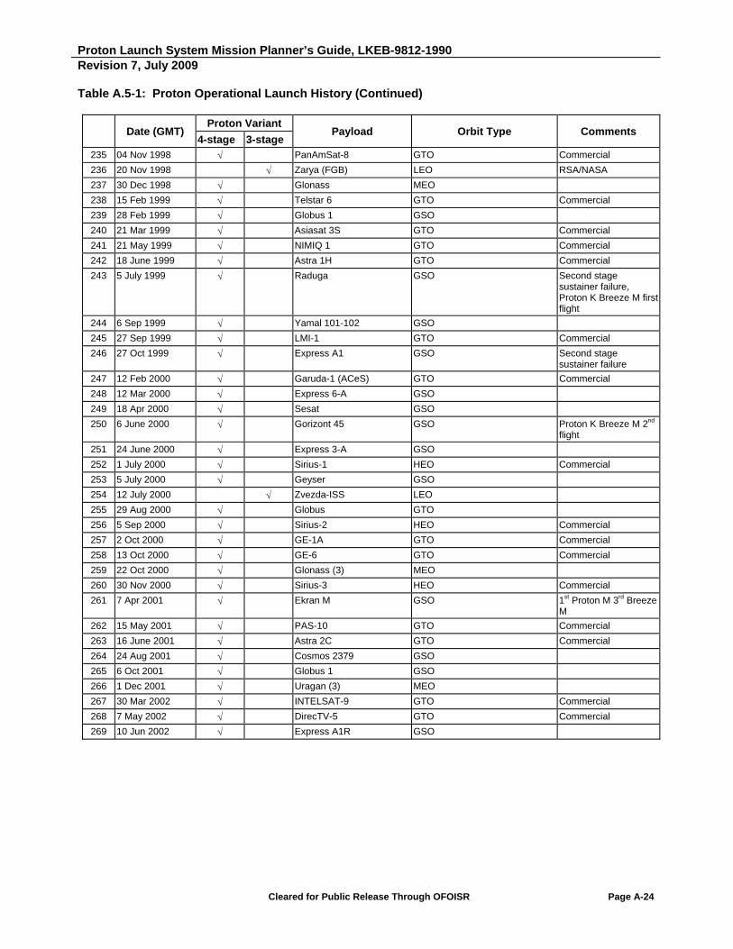
Proton Launch System Mission Planner’s Guide, LKEB-9812-1990 Revision 7, July 2009
Cleared for Public Release Through OFOISR Page A-24
Table A.5-1: Proton Operational Launch History (Continued)
Date (GMT)
Proton Variant Payload Orbit Type Comments
4-stage 3-stage 235 04 Nov 1998 PanAmSat-8 GTO Commercial
236 20 Nov 1998 Zarya (FGB) LEO RSA/NASA
237 30 Dec 1998 Glonass MEO
238 15 Feb 1999 Telstar 6 GTO Commercial
239 28 Feb 1999 Globus 1 GSO
240 21 Mar 1999 Asiasat 3S GTO Commercial
241 21 May 1999 NIMIQ 1 GTO Commercial
242 18 June 1999 Astra 1H GTO Commercial
243 5 July 1999 Raduga GSO Second stage sustainer failure, Proton K Breeze M firstflight
244 6 Sep 1999 Yamal 101-102 GSO
245 27 Sep 1999 LMI-1 GTO Commercial
246 27 Oct 1999 Express A1 GSO Second stage sustainer failure
247 12 Feb 2000 Garuda-1 (ACeS) GTO Commercial
248 12 Mar 2000 Express 6-A GSO
249 18 Apr 2000 Sesat GSO
250 6 June 2000 Gorizont 45 GSO Proton K Breeze M 2nd flight
251 24 June 2000 Express 3-A GSO
252 1 July 2000 Sirius-1 HEO Commercial
253 5 July 2000 Geyser GSO
254 12 July 2000 Zvezda-ISS LEO
255 29 Aug 2000 Globus GTO
256 5 Sep 2000 Sirius-2 HEO Commercial
257 2 Oct 2000 GE-1A GTO Commercial
258 13 Oct 2000 GE-6 GTO Commercial
259 22 Oct 2000 Glonass (3) MEO
260 30 Nov 2000 Sirius-3 HEO Commercial
261 7 Apr 2001 Ekran M GSO 1st Proton M 3rd Breeze M
262 15 May 2001 PAS-10 GTO Commercial
263 16 June 2001 Astra 2C GTO Commercial
264 24 Aug 2001 Cosmos 2379 GSO
265 6 Oct 2001 Globus 1 GSO
266 1 Dec 2001 Uragan (3) MEO
267 30 Mar 2002 INTELSAT-9 GTO Commercial
268 7 May 2002 DirecTV-5 GTO Commercial
269 10 Jun 2002 Express A1R GSO

Proton Launch System Mission Planner’s Guide, LKEB-9812-1990 Revision 7, July 2009
Cleared for Public Release Through OFOISR Page A-25
Table A.5-1: Proton Operational Launch History (Continued)
Date (GMT)
Proton Variant Payload Orbit Type Comments
4-stage 3-stage 270 25 Jul 2002 Araks LEO
271 22 Aug 2002 Echostar-8 GTO Commercial
272 17 Oct 2002 Integral HEO ESA
273 26 Nov 2002 F Astra-1K GTO Commercial - Block DM propulsion unit failure
274 25 Dec 2002 Uragan MEO
275 30 Dec 2002 Nimiq-2 GTO Commercial - 2nd Proton M 4th Breeze M
276 24 Apr 2003 Kosmos GSO
277 7 Jun 2003 AMC-9 GTO Commercial
278 24 Nov 2003 Yamal-200 GEO
279 10 Dec 2003 Glonass MEO
280 29 Dec 2003 Express GSO
281 16 Mar 2004 W3A GTO Commercial - 3rd Proton M 7th Breeze M
282 27 Mar 2004 Globus GSO
283 27 Apr 2004 Express AM11 GSO
284 17 Jun 2004 INTELSAT 10-02 GTO Commercial
285 5 Aug 2004 Amazonas-1 GTO Commercial
286 14 Oct 2004 AMC 15 GTO Commercial
287 30 Oct 2004 Express AM1 GSO
288 26 Dec 2004 Glonass MEO
289 3 Feb 2005 AMC-12 GTO
290 29 Mar 2005 Express AM2 GSO
291 22 May 2005 DirecTV- 8 GTO
292 24 Jun 2005 Express AM3 GSO
293 9 Sep 2005 Anik F1R GTO
294 25 Dec 2005 Glonass MEO
295 29 Dec 2005 AMC-23 GTO
296 28 Feb 2006 F Arabsat-4A GTO
297 17 Jun 2006 KazSat GSO
298 4 Aug 2006 Hotbird 8 GTO
299 8 Nov 2006 Arabsat-4B GTO
300 11 Dec 2006 Measat 3 GTO
301 25 Dec 2006 Glonass MEO
302 9 Apr 2007 Anik F3 GTO
303 7 Jul 2007 DirecTV-10 GTO
304 5 Sep 2007 F JCSat-11 GTO
305 26 Oct 2007 Glonass MEO
306 17 Nov 2007 SIRIUS 4 GTO
307 9 Dec 2007 Cosmos 2434 GSO
308 25 Dec 2007 Glonass MEO
309 28 Jan 2008 Express-AM33 GSO
310 10 Feb 2008 Thor 5 GSO
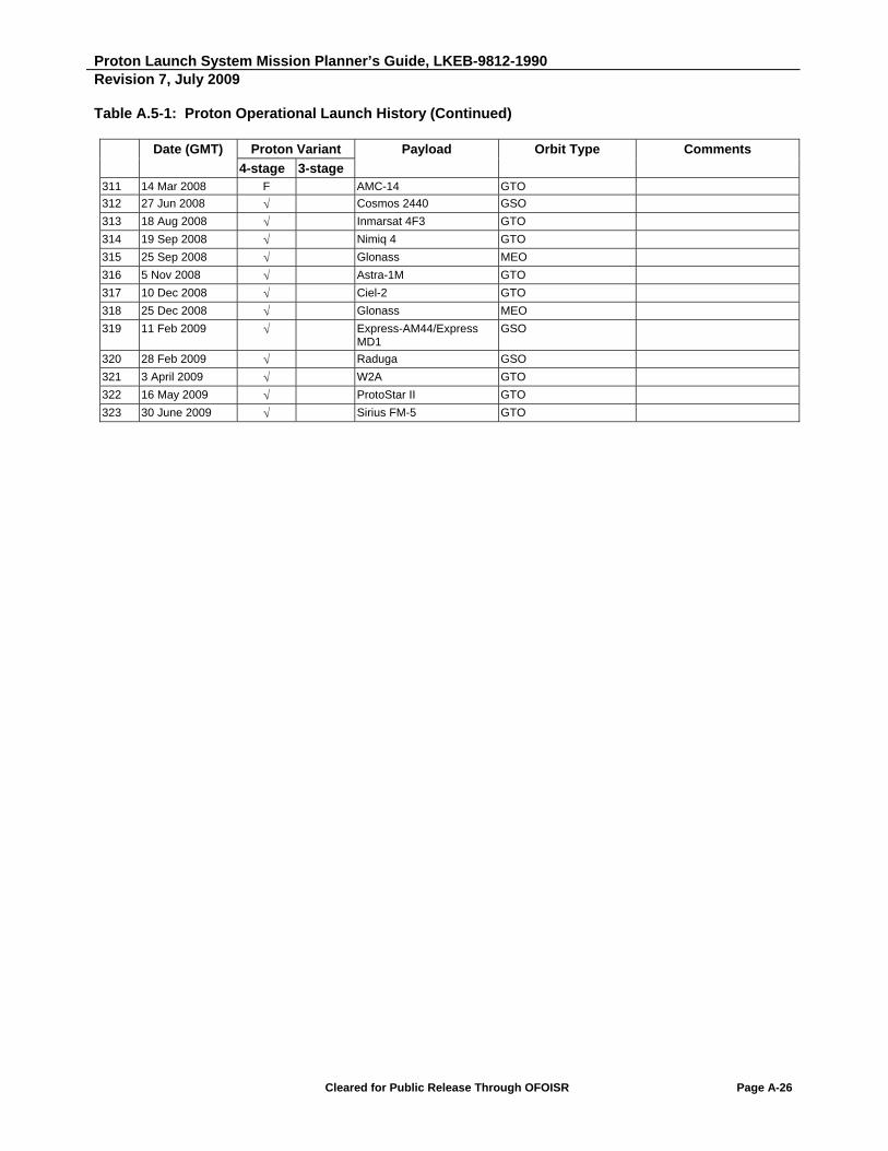
Proton Launch System Mission Planner’s Guide, LKEB-9812-1990 Revision 7, July 2009
Cleared for Public Release Through OFOISR Page A-26
Table A.5-1: Proton Operational Launch History (Continued)
Date (GMT) Proton Variant Payload Orbit Type Comments
4-stage 3-stage 311 14 Mar 2008 F AMC-14 GTO
312 27 Jun 2008 Cosmos 2440 GSO
313 18 Aug 2008 Inmarsat 4F3 GTO
314 19 Sep 2008 Nimiq 4 GTO
315 25 Sep 2008 Glonass MEO
316 5 Nov 2008 Astra-1M GTO
317 10 Dec 2008 Ciel-2 GTO
318 25 Dec 2008 Glonass MEO
319 11 Feb 2009 Express-AM44/Express MD1
GSO
320 28 Feb 2009 Raduga GSO
321 3 April 2009 W2A GTO
322 16 May 2009 ProtoStar II GTO
323 30 June 2009 Sirius FM-5 GTO

Proton Launch System Mission Planner’s Guide, LKEB-9812-1990 Revision 7, July 2009
Cleared for Public Release Through OFOISR Page A-27
A.6 FAILURES CAUSES AND CORRECTIVE ACTION
Data was provided by Khrunichev Space Center, which has been placed into the public domain. Failures are noted in Tables A.4-2 and A.5-1.
a) 1970: After 128.3 seconds of flight, 1st stage engine cutoff due to false alarm from the LV safety system activated by the engine pressure gage. Manufacturing defect. Additional check of gages introduced at point of installation.
b) 1972: After 181.9 seconds of flight, 2nd stage automated stabilization system failure due to a relay short circuit in the "pitch" and "yawing" channels caused by elastic deformation of the device housing (which operates in vacuum). Design defect. Design of instruments upgraded and additional testing undertaken.
c) 1975: Failure of 4th stage oxidizer booster pump. Manufacturing/design defect. Cryogen-helium condensate freezing. Booster pump blowing introduced.
d) 1977: After 40.13 seconds of flight, spontaneous deflection of 1st stage engine, loss of stability and engine cutoff at 53.68 seconds into the flight safety system command. Steering failure due to spool-and-sleeve pair manufacturing defect (faulty liner), which caused penetration of hard particles under liner rim and resulted in spool-and-sleeve seizure.
e) 1978: After 87 seconds of flight, loss of stability commenced due to error of 1st stage second combustion chamber steering gear. High temperature impact on cables due to heptyl leak into second block engine compartment. Leak likely developed at heptyl feed coupling to gas generator. Coupling upgraded.
f) 1978: Flight terminated after 259.1 seconds due to loss of LV stability. Automatic stabilization system electric circuit failure in rear compartment of 2nd stage caused by hot gases leaking from second engine gas inlet due to faulty sealing of pressure gage. Gage attaching point upgraded.
g) 1978: After 235.62 seconds of flight, 2nd stage engine shutoff and loss of stability caused by a turbine part igniting in turbo pump gas tract followed by gas inlet destruction and hot air ejection into 2nd rear section. Engine design upgraded.
h) 1982: At 45.15 seconds into the flight, major malfunctioning of 1st stage engine fifth chamber. Flight terminated by LV safety system command. Failure caused by steering motor malfunctioning: first stage of hydraulic booster got out of balance coupled with booster dynamic excitation at resonance frequencies. Hydraulic booster design redefined.
i) 1982: 2nd stage engine failure caused by high-frequency vibrations. Engine design upgraded.
j) 1986: Control system failure due to brief relay contact separation caused by engine vibration. Upgrading included introduction of self-latching action capability for program power distributor shaft.
k) 1987: 4th stage control system failure due to component (relay) defect. Manufacturing defect. Remedial program introduced at supplier's factory. Inspection made more stringent.
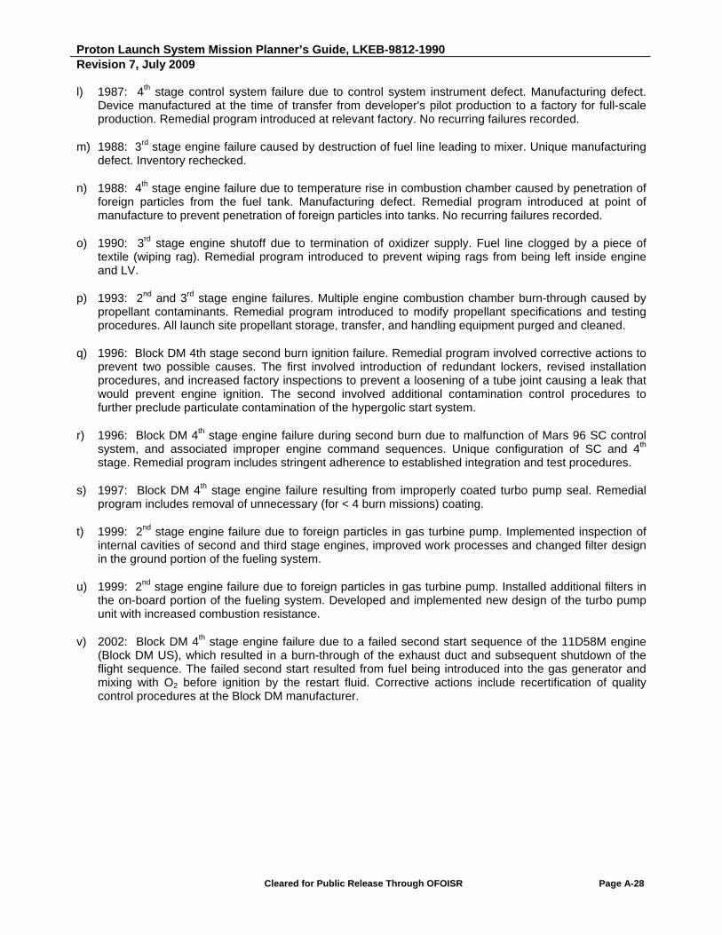
Proton Launch System Mission Planner’s Guide, LKEB-9812-1990 Revision 7, July 2009
Cleared for Public Release Through OFOISR Page A-28
l) 1987: 4th stage control system failure due to control system instrument defect. Manufacturing defect. Device manufactured at the time of transfer from developer's pilot production to a factory for full-scale production. Remedial program introduced at relevant factory. No recurring failures recorded.
m) 1988: 3rd stage engine failure caused by destruction of fuel line leading to mixer. Unique manufacturing defect. Inventory rechecked.
n) 1988: 4th stage engine failure due to temperature rise in combustion chamber caused by penetration of foreign particles from the fuel tank. Manufacturing defect. Remedial program introduced at point of manufacture to prevent penetration of foreign particles into tanks. No recurring failures recorded.
o) 1990: 3rd stage engine shutoff due to termination of oxidizer supply. Fuel line clogged by a piece of textile (wiping rag). Remedial program introduced to prevent wiping rags from being left inside engine and LV.
p) 1993: 2nd and 3rd stage engine failures. Multiple engine combustion chamber burn-through caused by propellant contaminants. Remedial program introduced to modify propellant specifications and testing procedures. All launch site propellant storage, transfer, and handling equipment purged and cleaned.
q) 1996: Block DM 4th stage second burn ignition failure. Remedial program involved corrective actions to prevent two possible causes. The first involved introduction of redundant lockers, revised installation procedures, and increased factory inspections to prevent a loosening of a tube joint causing a leak that would prevent engine ignition. The second involved additional contamination control procedures to further preclude particulate contamination of the hypergolic start system.
r) 1996: Block DM 4th stage engine failure during second burn due to malfunction of Mars 96 SC control system, and associated improper engine command sequences. Unique configuration of SC and 4th stage. Remedial program includes stringent adherence to established integration and test procedures.
s) 1997: Block DM 4th stage engine failure resulting from improperly coated turbo pump seal. Remedial program includes removal of unnecessary (for < 4 burn missions) coating.
t) 1999: 2nd stage engine failure due to foreign particles in gas turbine pump. Implemented inspection of internal cavities of second and third stage engines, improved work processes and changed filter design in the ground portion of the fueling system.
u) 1999: 2nd stage engine failure due to foreign particles in gas turbine pump. Installed additional filters in the on-board portion of the fueling system. Developed and implemented new design of the turbo pump unit with increased combustion resistance.
v) 2002: Block DM 4th stage engine failure due to a failed second start sequence of the 11D58M engine (Block DM US), which resulted in a burn-through of the exhaust duct and subsequent shutdown of the flight sequence. The failed second start resulted from fuel being introduced into the gas generator and mixing with O2 before ignition by the restart fluid. Corrective actions include recertification of quality control procedures at the Block DM manufacturer.

Proton Launch System Mission Planner’s Guide, LKEB-9812-1990 Revision 7, July 2009
Cleared for Public Release Through OFOISR Page A-29
w) 2006: Breeze M 4th stage engine failure. Entry of foreign object debris from oxidizer feed line to the booster turbine inlet. Corrective actions included implementing procedures to validate the cleanliness of oxidizer feed line piping on Breeze M Upper Stage engines.
x) 2007: LV stage 1/stage 2 stage separation failure. Burnthrough of the LV stage 1/stage 2 separation pyrobolt actuation cable. Corrective action is to over-wrap the pyrobolt wiring harness by two layers of asbestos tape with 50% overlap. This increases the heat resistance to well over 400°C, the harness melting point. Additionally the ring and harness are jointly over-wrapped with two layers of tape with 50% overlap impregnated with glue, and the harness was re-routed away from the exhaust gas.
y) 2008: Breeze M 4th stage engine failure. US main engine gas duct burnthrough resulting from the combined maximum environments, gas temperature, gas pressure and thin-walled duct. Corrective action is the implementation of quality provisions that ensures a conduit wall thickness greater than or equal to the 2.5 mm requirement.

Intentionally Blank

Proton Launch System Mission Planner’s Guide
APPENDIX B
Quality Management System

Proton Launch System Mission Planner’s Guide, LKEB-9812-1990 Revision 7, July 2009
Cleared for Public Release Through OFOISR Page B-1
B. QUALITY MANAGEMENT SYSTEM
B.1 Proton Quality Assurance Plan
B.1.1 KhSC Quality Management Overview
ILS Proton launch vehicle services are implemented by Khrunichev State Research and Production Space Center (KhSC) in Moscow, Russia. KhSC operates an ISO 9001 registered Quality Management System (QMS) and is accredited through the Russian Federation Roscosmos/Ministry of Defense/Gosstandart under registration number FSS KT 134.03.3.1.00000.31.05 dated 27 December 2005. Recertification to ISO 9001-2008 will be completed in 2009.
The scope of compliance applies to design, development, test, manufacture, and assembly of advanced technology systems for space and defense, including space systems, launch systems, and ground systems. Adherence to ISO 9001’s quality standard is revalidated at yearly intervals by Roscosmos.
ISO 9001/9002 is fulfilled through implementation of KhSC Policies in the field of quality and performance of work in conformance with procedures and practices that are described in the approved KhSC Corporate Quality Management System Manual (RK 737.340.01). The Manual is structured in a manner similar to that of the EN 9100 standard and includes a documented process-oriented approach to designing (design engineering), refining, testing, manufacturing, and assembling advanced technology systems for space and defense. The KhSC Quality Manual (KQM) is continually updated and revised in order to reflect the continuous improvement of QMS processes.
In accordance with the standards documents, the following are the basic processes of the KhSC corporate quality management system employed in the creation, manufacture, and preparation of rocket-space technology articles for use:
Management processes
Resource supply processes
Product life cycle processes
Measurement, analysis and improvement processes
B.1.2 KhSC Quality Management Organization
The Russian Space Agency (Roscosmos), Russian Standards Organization (Rostekhregulirovanie), and Russian Federation Ministry of Defense (MoD) provide joint oversight of compliance with technical and quality provisions and standards, and certify conformance to, quality standards and instructions.
Responsibility and authority for the function and the improvement of KhSC QMS results to satisfy quality requirements for manufactured products is under the KhSC Deputy Director General for Quality, who reports directly to the KhSC Director General.
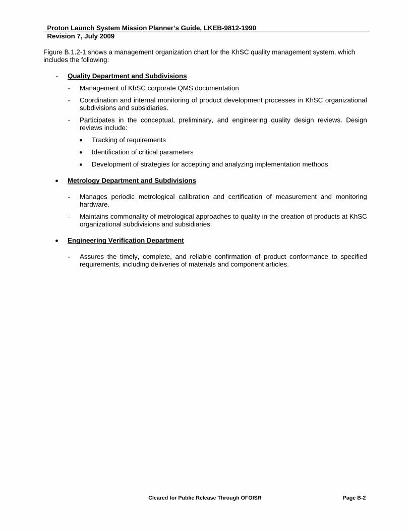
Proton Launch System Mission Planner’s Guide, LKEB-9812-1990 Revision 7, July 2009
Cleared for Public Release Through OFOISR Page B-2
Figure B.1.2-1 shows a management organization chart for the KhSC quality management system, which includes the following:
- Quality Department and Subdivisions
- Management of KhSC corporate QMS documentation
- Coordination and internal monitoring of product development processes in KhSC organizational subdivisions and subsidiaries.
- Participates in the conceptual, preliminary, and engineering quality design reviews. Design reviews include:
Tracking of requirements
Identification of critical parameters
Development of strategies for accepting and analyzing implementation methods
Metrology Department and Subdivisions
- Manages periodic metrological calibration and certification of measurement and monitoring hardware.
- Maintains commonality of metrological approaches to quality in the creation of products at KhSC organizational subdivisions and subsidiaries.
Engineering Verification Department
- Assures the timely, complete, and reliable confirmation of product conformance to specified requirements, including deliveries of materials and component articles.
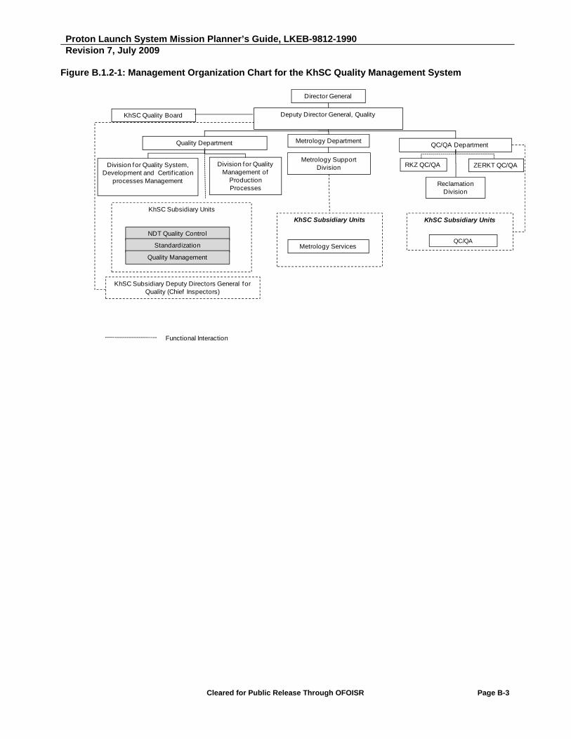
Proton Launch System Mission Planner’s Guide, LKEB-9812-1990 Revision 7, July 2009
Cleared for Public Release Through OFOISR Page B-3
Figure B.1.2-1: Management Organization Chart for the KhSC Quality Management System
Director General
KhSC Quality Board Deputy Director General, Quality
Quality Department
Division for Quality System, Development and Certif ication
processes Management
Division for Quality Management of
Production Processes
Metrology Department
Metrology Support Division
KhSC Subsidiary Units
NDT Quality Control
Standardization
KhSC Subsidiary Deputy Directors General for Quality (Chief Inspectors)
KhSC Subsidiary Units
Metrology Services
Quality Management
QC/QA Department
RKZ QC/QA ZERKT QC/QA
Reclamation Division
KhSC Subsidiary Units
Functional Interaction
QC/QA

Proton Launch System Mission Planner’s Guide, LKEB-9812-1990 Revision 7, July 2009
Cleared for Public Release Through OFOISR Page B-4
B.1.3 KhSC Quality Management Processes/Procedures
To achieve maximum effectiveness and continued customer satisfaction, a required level of quality is ensured through:
Physical examination (inspection)
Measurement
Test
Process monitoring, and/or employment of other methods required to assure compliance of deliverable products and services with quality requirements.
Independent verification includes:
Mandatory inspection points for processes
Documentation (procedures) on work performance
Manufacturing and testing
Sample (specimen) collection plans
Statistical methods
Data analysis
Trending, and
Other engineering methods and tools that are suitable for the articles or processes being verified.
Documented procedures are established and maintained for planning, performing, reporting and follow up internal audits. The KhSC internal audit program coordinates with other audit organizations, including government audit teams, to maximize effectiveness. Quality Assurance has the responsibility for the management and oversight of the internal audit program. Auditors are independent of the party responsible for taking corrective action.
The quality department produces metrics and trend data on a monthly and on an as-needed basis. This data is a summary of trends in the areas of Production, Procurement, and Launch Site nonconformance data. This data is used as an indicator of the performance in those areas. In addition, special trend data such as by Part Number or specific vehicle are produced on an as-needed basis. The level of detail of the data provided is restricted by Russian Security requirements.
Quality is a part of every process at KhSC, and this is reflected in the revisions to the KhSC organizational subdivision and subsidiary quality manuals that reflect the activities specific to ILS commercial Proton launches. Commercial mission analysis and design, and commercial spacecraft ICD verification have been added to the normal vehicle integration work flow, with specific provisions made to provide customer visibility into these processes, as well as into the contracting, launch vehicle fabrication, assembly and test, and launch processing activities.
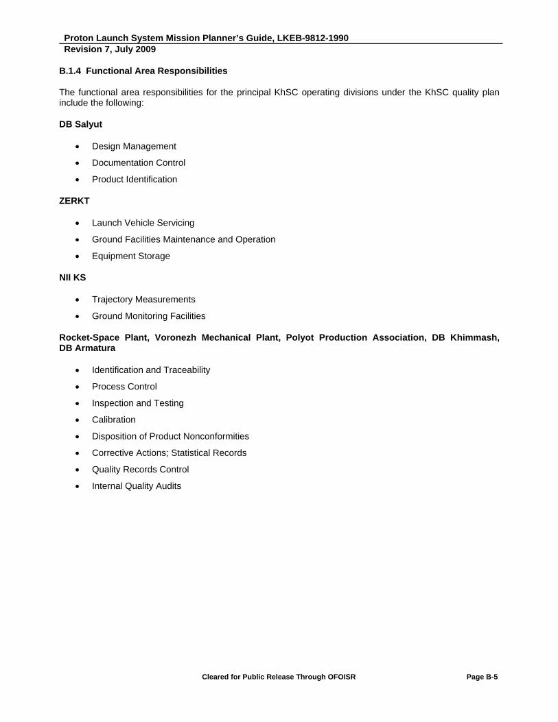
Proton Launch System Mission Planner’s Guide, LKEB-9812-1990 Revision 7, July 2009
Cleared for Public Release Through OFOISR Page B-5
B.1.4 Functional Area Responsibilities
The functional area responsibilities for the principal KhSC operating divisions under the KhSC quality plan include the following:
DB Salyut
Design Management
Documentation Control
Product Identification
ZERKT
Launch Vehicle Servicing
Ground Facilities Maintenance and Operation
Equipment Storage
NII KS
Trajectory Measurements
Ground Monitoring Facilities
Rocket-Space Plant, Voronezh Mechanical Plant, Polyot Production Association, DB Khimmash, DB Armatura
Identification and Traceability
Process Control
Inspection and Testing
Calibration
Disposition of Product Nonconformities
Corrective Actions; Statistical Records
Quality Records Control
Internal Quality Audits

Proton Launch System Mission Planner’s Guide, LKEB-9812-1990 Revision 7, July 2009
Cleared for Public Release Through OFOISR Page B-6
B.1.5 Quality Management System Documentation
The KhSC corporate quality management system documentation encompasses all requirements of the ISO-9001 EN9100 standard, and includes the following:
KhSC Quality Policy
KhSC standards and provisions:
RK 737.340.01-2009, "Quality Manual. Corporate Quality Management System. Requirements"
STP 737.0.2, "Analysis by Senior Management. Work Procedure"
STP 737.0.3, "Measurement, Analysis, and Improvement. Basic Provisions"
STP 737.0.4, "Internal Audits. Planning and Conduct"
STP 737.0.5, "Corrective Actions. Basic Provisions"
STP 737.0.6, "Preventive Actions. Basic Provisions”
STP 737.0.7, "Management of Nonconformities. Basic Provisions"
STP 737.0.8, "Purchasing Quality Management. Basic Provisions"
STP 737.0.9, "Processes for Controlling Monitoring and Measurement Devices"
STP 737.0.10, "Verification and Calibration of Measurement Devices. Organization and Procedure"
STP 737.0.11, "Organizing Performance of Work to Coordinate Documentation with the Metrological Office"
STP 737.0.12, "Metrological Expert Review of Engineering Documentation. Organization and Procedure"
STP 737.0.15, "Entry Control. General Provisions"
STP 737.0.17, "Company Standards. General Provisions"
STP 737.1.1, "Procedure for Company Standard Development and Revision"
STP 737.1.2, "Manufacturing Process"
STP 737.2.11, "Quality Management of the Design Process and the Development of Design Documentation"
STP 737.3.10, "Maintenance and Preparation for Operation"
Provision "Selection and Disposition of Personnel at the Company"
Provision No. 17, "Certification of KhSC Managers, Engineers and Technicians, and Other Specialists"
Provision "System of Training, Retraining, and Occupational Development of Personnel and KhSC and Its Subsidiaries"
Planning documents (plans, schedules, programs), intended to maintain quality management system processes in working order and continually improve their effectiveness.
Documentary certification (entries), maintenance of which is called for in regulatory and engineering documentation.

Proton Launch System Mission Planner’s Guide, LKEB-9812-1990 Revision 7, July 2009
Cleared for Public Release Through OFOISR Page B-7
B.1.6 Proton Supplier Network
KhSC uses a network of more than 60 Russian subcontractors, all of whom have demonstrated their ability to function as proven suppliers to the Russian space industry. In addition, six suppliers are based in Ukraine, and one operates from Sweden (RUAG Aerospace Sweden AB). Ninety-seven percent (97%) of KhSC’s suppliers have been with the Proton program since its inception in the early 1960’s. Long-term, stable subcontractor relationships are emphasized at KhSC, and by the Russian government. This allows the implementation of multi-year contracts and long-term working relationships among key personnel. All Proton subcontractors are certified and monitored by Russian Federal agencies, and are debt free with a stable financial base. All Proton subcontractors are subject to the same quality standards as KhSC itself; all must have ISO 9001/9002 registered quality management systems and be accredited through the Russian Federation Roscosmos/Ministry of Defense/Gosstandart organizations. In addition, KhSC levies and monitors its own specific schedule and quality requirements, and maintains oversight personnel at the facilities of key subcontractors.
Subcontractor auditing is specified in all KhSC procurement contracts, and is implemented according to a Russian government approved plan described in GOST R ISO 10011-1 and STP 104-892 KhSC company standard. Audits focus on the following issues:
Incoming inspection procedures
Qualification test results
Nonconformance disposition procedures
Production anomaly and Customer complaint histories
Corrective actions and nonconformance mitigation guidelines
The audits are witnessed by subcontractor representatives, and the final audit report is signed by both the subcontractor and a Russian Ministry of Defense inspector.
Proton Launch System Mission Planner’s Guide, LKEB-9812-1990 Revision 7, July 2009
Cleared for Public Release Through OFOISR Page B-8
B.1.7 Launch Vehicle Production and Integration
The launch vehicle production and integration process has a test and quality inspection plan that covers the areas of design, production preparation, fabrication, assembly, testing, final acceptance, transportation, and launch site operations.
B.1.7.1 Design Configuration Management
KhSC executes configuration management using Russian Federation-standardized benchmark procedures and processes on the Proton program. Senior engineering and production management provide program-wide communication of all proposed configuration changes, and has representation from Engineering, Production, Parts/Materials/Processes, and Launch Operations. Functional, allocated, and product baselines have been established.
The functional baseline consists of documents such as the system and segment specifications, integration interface control documents, and measurements and mission-discrete lists. The allocated baseline consists of the configuration integration specifications, design requirements documents, and design change documents. The product baseline consists of the process and material specifications, program-released drawings, software development files, and software version description.
B.1.7.2 Acceptance Requirements
The Proton M program uses the proven qualification and acceptance processes for Proton development as were used for all prior Proton upgrade programs. The governing requirements for qualification and acceptance environments are documented in the Russian Federation Standard GOST R ISO-9001and KhSC Company Standards.
All new Proton components undergo a full qualification testing cycle. All existing vehicle components are assessed against Proton specifications by qualified responsible engineers to determine which components meet all predicted environments with the required margin.
Component qualification and acceptance test requirements are captured in test requirements documents and used to maintain the qualification and acceptance test procedures with the component vendors. In order to verify the quality characteristics of components, qualification and acceptance tests are performed under flight-like temperature, humidity, vacuum, vibration, and shock conditions. System-level testing is then performed to further validate component functionality and integration.

Proton Launch System Mission Planner’s Guide, LKEB-9812-1990 Revision 7, July 2009
Cleared for Public Release Through OFOISR Page B-9
Each hardware-responsible engineer is responsible for full ownership of their respective components or subsystems that includes the following qualification and acceptance responsibilities: identifying design and performance specifications, defining component or subsystem qualification and acceptance requirements, working with the component vendor to mutually define and maintain the component qualification and acceptance test procedures, and reviewing and buy-off of all qualification and acceptance test reports or analyses. All Proton qualification units are production units that successfully passed acceptance testing.
B.1.8 Quality Assurance Participation
Quality Assurance representatives participate with the responsible engineer in each step of the component buy-off process, from receipt-and-inspection to review of the test reports. Quality Assurance provides a positive control system for identifying the inspection and acceptance status of products.
B.1.9 Personnel Training
Skilled job performers are essential to the achievement of high product quality. In order to maintain the specialized skills KhSC needs, personnel training/re-training programs are conducted annually. These programs include:
A 550-hour course of training and certification in job related skills upon initial employment
Annual re-certification of job performers for critical operations
Annual re-certification of job performers for the supporting activities required by their jobs, including knowledge of safety and environmental regulations
Re-certification of personnel in the event of primary occupational work interruptions of longer than three months
70-hour skill upgrading courses (at KhSC)
Skill upgrading assignments to Russian scientific centers and Russian State Standards institutions (50 hours)
Advanced training courses at European training centers (Germany, England).
B.1.10 Quality Parameter Trend Analysis
KhSC QA personnel monitor and control all important technological processes. As part of this effort statistical stability checks are made on all key parameters. The data gathered is used to define corrective actions and improve process capability.
KhSC monitoring of trends provides feedback for continuous quality improvement and internal audit results, including factory build nonconformance trends and supplier trends.

Proton Launch System Mission Planner’s Guide, LKEB-9812-1990 Revision 7, July 2009
Cleared for Public Release Through OFOISR Page B-10
B.1.11 Corrective Action Plans and Continuous Improvement Program
Corrective action plans are created based on data from the following:
Nonconformance preventive measures at production, testing and operation phases
Specifications compliance audit results
Actions based on factory/shop level board reports
Quality board findings and “quality awareness day” results
Internal audits for compliance with regulatory procedures
Quality management recommendations for improvement of technical inspection processes and techniques
Actions based on vendor audit results
Continuous improvement program is developed annually and consists of the following sections:
Requirements compliance — designer’s oversight of design and operational documentation during production and at the launch complex
Monitoring of vendors
Production, test and service equipment upgrades
Application of new quality control non-destructive testing methods
Process parameters stability control
Personnel training
B.1.12 Customer Visibility
ILS ensures customer visibility into all mission integration related activities regarding the Proton launch vehicle and its Upper Stages through customer participation in all Technical Interchange Meetings (TIMs), Preliminary and Critical Design Reviews (PDR and CDR), fitcheck activities, Launch Vehicle Quality Review (LVQR), two Launch Site Intergovernmental Commission Meetings, Countdown and Launch activities, and the Post Launch Meeting and Report. In addition, ILS produces a Quarterly Quality Report that is provided to all Customers to detail the status of Production related Quality Trends and actual hardware quality status.
TIM’s occur no later than as needed, throughout the mission integration process, and cover all aspects of the mission integration effort, primarily through the progressive development of the mission Interface Control Document (ICD) and through reporting of supporting analysis activities. Special purpose TIMs, such as the Ground Operations Working Group (GOWG) are also scheduled as needed. The PDR represents a first complete overview of the work documented in the ICD, and typically occurs at approximately L-12 months. The CDR occurs when approximately 90% of mission integration activities are complete, at roughly L-6 months. The fitcheck is a test of the adapter and separation system with the SC, and usually occurs only with a new or substantially modified spacecraft bus. When necessary, it is held at L-4 months. A LVQR of the Proton M, Breeze M, Payload Fairing and Adapter/Separation System takes place at L-2 months.
Proton Launch System Mission Planner’s Guide, LKEB-9812-1990 Revision 7, July 2009
Cleared for Public Release Through OFOISR Page B-11
The first Intergovernmental Commission Meeting takes place at L-6 days, when senior representatives of all parties concerned with the LV, US, SC and launch base meet to approve roll-out of the ILV to the launch pad. The second such meeting occurs at L-7 hours, when the same representatives meet to give final approval to LV fueling and final countdown operations. During the launch itself, customer representatives play an active role in preparing the SC for launch and determining the final GO/NO GO status of the overall launch system. Finally, a Post-Launch Meeting is held, and a Final Report is prepared, two months after lift-off, to review the success of the mission and any applicable lessons learned, with the intent of constantly improving the Proton mission integration and flight experience.
For ongoing insight into LV manufacturing quality, ILS produces a Quarterly Quality report that provides factory quality trends, as well as the actual hardware quality status for each Proton and Breeze M stage.
B.1.13 Hardware Evolution Design Development Processes
KhSC’s standard ISO 9001-based design development policy is used as documented in the KQM, to control and verify that the design of all Proton products meet the specified requirements. The KQM, policies, procedures, and practices identify the design activities, assigned responsibilities for implementing them, and defined and controlled organizational interfaces. A standard development cycle is followed: conceptual design and definition of system requirements, system requirements review, preliminary design, preliminary design review, detailed design, tailored critical design review, component qualification and acceptance, and launch site pathfinder.
The evolved Proton vehicle family was developed to satisfy the requirements of both commercial and Russian Federation customers. The Roscosmos, the Russian Ministry of Defense and its various support organizations, including the GOSS Standardization Committee, the Institute for Machine Building and the Test and Certification Institute, provide technical and programmatic oversight. The Proton development program has now successfully completed the development, production and launch of the first flight articles of the Proton M and Breeze M, the Phase I-enhanced Proton M/Breeze M, the Phase II-enhanced Proton M/Breeze M, and most of the upgrades for the Phase III-enhanced Proton M/Breeze M.
B.1.13.1 Proton M/Breeze M Guidance, Navigation and Control System Hardware and Software Development, Qualification and Testing
Testing and qualification of the Proton M Guidance, Navigation and Control (GN&C) system was conducted through a full set of procedures carried out in accordance with the requirements of Russian government standards, including four principal phases:
1. Each major component and subsystem was put through “stand-alone” laboratory tests that exposed it to all anticipated flight loads (temperature, pressure, vibration, etc.).
2. These components and subsystems were subjected to “joint acceptance tests,” conducted with the participation of Russian state inspection organizations.

Proton Launch System Mission Planner’s Guide, LKEB-9812-1990 Revision 7, July 2009
Cleared for Public Release Through OFOISR Page B-12
3. The integrated “flight-like” GN&C system was operated through a comprehensive and varied series of simulations of the anticipated flight profile, using a program-controlled “full-size simulation dynamic stand” that verified both the control system itself and the control system’s actuators.
4. The first flight article of the Proton M launch vehicle’s GN&C system was subjected to comprehensive acceptance testing at the facilities of the company that manufactured the system, and again at the electrical and electronic checkout area of the launch site. These tests will, of course, be repeated for each subsequent flight article.
The Proton M flight control system software has been developed and tested in special simulation test stands at the facilities of the company that developed the system. The software has also been tested many times at the electrical and electronic checkout area at the KhSC factory, and in the equivalent area at the launch site.
Design of the flight software involves the development of a number of standard trajectories and event profiles, which are modified as needed through the generation of mission-specific mission constants.
Testing of the standard flight software occurs in two principal phases:
1. The software elements are put through stand-alone tests and debugging, using standard software test tools and facilities, as well as the On-Board Digital Computer (OBDC), without hooking up the control system related launch vehicle actuators and instrumentation.
2. Integrated tests which exercise all control system operating modes are performed on an “analogue and digital complex” (simulation rig) using the complete set of OBDC flight control programs, as well as on an “integrated system test console” (breadboard), using the complete control system instrumentation package which would be used in flight. These tests are conducted in conjunction with the hardware tests of the GN&C system.
These test conditions envelope the anticipated range of operating environments, with appropriate margin, to ensure system reliability under all expected real world flight conditions.
The mission design process flow involves multiple agencies in the development and validation of the mission design; including KhSC, KhSC’s control system subcontractors (MOKB Mars for the Breeze M; NII AP for the Proton M), and the Ballistics Center (a Russian government agency).

Proton Launch System Mission Planner’s Guide, LKEB-9812-1990 Revision 7, July 2009
Cleared for Public Release Through OFOISR Page B-13
B.1.14 Quality Initiatives
As discussed previously, the vertical integration of Proton key suppliers under KhSC had prompted efforts to consolidate the various suppliers’ QMS into the KhSC QMS.
The following are currently implemented:
A series of audits and reviews:
- Using a launch vehicle as the audit article, Russian independent auditors carried out an extensive examination of the QMS at KhSC and KhimMASH (Federal Certification Center for Space Technology) and of the launch vehicle processing at the launch site (Federal Space Center).
- Additional internal reviews of the Proton M and Breeze M components, manufacturing processes and key parameters.
- Procedure for implementing and evaluating launch site readiness.
- Audit of the Breeze M main engine test facilities.
- Expanded vendor audit plan.
- Review of contamination control processes and additional training and certification of the workforce.
- Comprehensive analysis of critical operations related to the key performance parameters of the Proton and Breeze M and of the Breeze M main engine.
Documentation of corporate quality management system processes.
Increase involvement of the KhSC design bureau in production and testing: the Chief Designer actually supervised the qualification testing mentioned below. Organizational changes formalize the Chief Designer involvement in launch vehicle production critical operations.
Completion of the qualification testing to validate the modified Breeze M engine design and the rework that was carried out on the previously accepted (including test firing) engines.
A complete reevaluation of the Breeze M engine reliability was conducted. The life time margin of the engine has more than doubled.
Creation of a single quality database.
General revision of Quality Control technical processes.

Proton Launch System Mission Planner’s Guide, LKEB-9812-1990 Revision 7, July 2009
Cleared for Public Release Through OFOISR Page B-14
The medium- and long-term initiatives will ensure the current drive towards an improved QMS is sustained over the long term. They include:
A number of certifications or recertifications:
- Recertification of the KhSC QMS to the Russian Federal standard and to the ISO 9001-2008 standard.
- Accreditation of the KhSC metrological services by the Federal Agency for Technical Regulation and Metrology.
- Certification and/or upgrading of the manufacturing processes of critical elements, including an independent audit.
Improvements to Quality Control:
- Development of methodology to make expanded use of statistical data in validating compliance to requirements.
- Use of state-of-the-art methods and techniques for Quality Control.
- Verification of key inspection points and associated methods (continuous recurring activity).
ILS and KhSC are committed to carrying through this broad undertaking to its completion and to inform customers along the way as progress is made. To that end, ILS/KhSC will provide the following expanded insight into Proton M/Breeze M Quality:
Increased scope of PDR and CDR Quality presentations, Standardized: PDR/CDR Quality presentations templates and contents. PDR presentations focus on QMS processes and procedures, while CDR presentations focus on the Quality status of mission specific Proton M Breeze M hardware.
Quarterly Quality Reports: In conjunction with internal ILS/KhSC monthly production and quality reviews, ILS produces quarterly quality reports that will be submitted to Customers and Insurance underwriters. This will provide insight into hardware status and trends.
Expanded LVQR: Prior to the start of the launch campaign, ILS, KhSC and the Customer review the entire Quality Package for the mission-specific LV hardware. The resulting LVQR presentation will be a comprehensive package reviewing the KhSC Quality processes and procedures, all first flight items and their qualification program, LV configuration, and all manufacturing anomalies/non-conformances. An example of the contents of the LV Quality Review Briefing is shown in Table B.1.14-1.

Proton Launch System Mission Planner’s Guide, LKEB-9812-1990 Revision 7, July 2009
Cleared for Public Release Through OFOISR Page B-15
Table B.1.14-1: LV Quality Review Briefing — Example Contents
Proton M Stages 1/2/3, Breeze M, PLF and Adapter Quality Reports (Main Components)
Configuration
Comparison with Previous Missions
First Launch Items
Mission-Specific Units
Software
Waivers
End of Warranty Components
Spares Plan
Flight Anomalies
Launch Complex Report
Maintenance — Ground Systems Test Results
Mission Specific Configuration
All Maintenance Processes Certified and Documented
Scheduled Maintenance:
- Processing Facility and Launch Pad STE — Monthly
- Filling Hall — Monthly
- Gas/water/power Supply and Ventilation Systems — Annual
- Climate Conditioning Systems of Integration and Testing Facilities — Daily
Ground Complex Validation for Integrated LV Operations

Intentionally Blank
Proton Launch System Mission Planner’s Guide
APPENDIX C
Requirements for Customer-Supplied Data

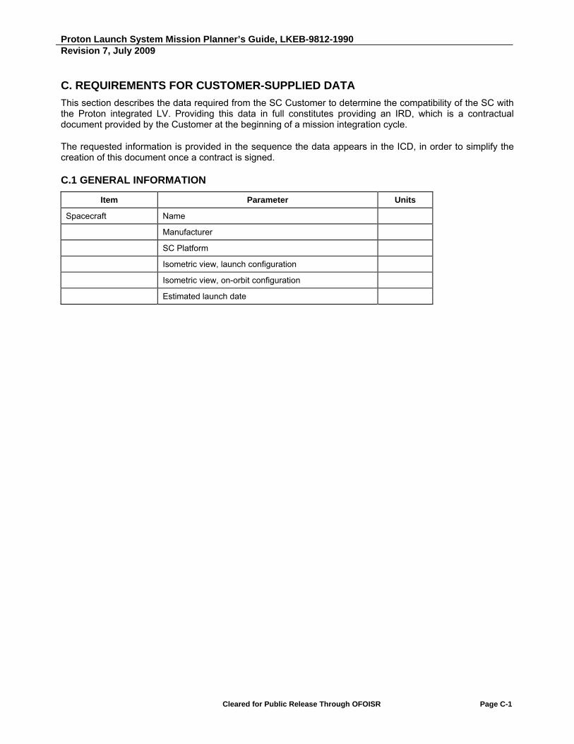
Proton Launch System Mission Planner’s Guide, LKEB-9812-1990 Revision 7, July 2009
Cleared for Public Release Through OFOISR Page C-1
C. REQUIREMENTS FOR CUSTOMER-SUPPLIED DATA
This section describes the data required from the SC Customer to determine the compatibility of the SC with the Proton integrated LV. Providing this data in full constitutes providing an IRD, which is a contractual document provided by the Customer at the beginning of a mission integration cycle.
The requested information is provided in the sequence the data appears in the ICD, in order to simplify the creation of this document once a contract is signed.
C.1 GENERAL INFORMATION
Item Parameter Units
Spacecraft Name
Manufacturer
SC Platform
Isometric view, launch configuration
Isometric view, on-orbit configuration
Estimated launch date

Proton Launch System Mission Planner’s Guide, LKEB-9812-1990 Revision 7, July 2009
Cleared for Public Release Through OFOISR Page C-2
C.2 INPUT DOCUMENTS
Item Parameter Units
SC Dynamic Model Per ILS SC Dynamic Model specification
SC Thermal Model Per ILS SC Thermal Model specification
SC Computer-Aided Design (CAD) Model
Per ILS SC Computer-Aided Design (CAD) Model specification
Launch Operations Plan Reference Section 5.3.5 of this Mission Planner’s Guide
Acoustic and Sine Vibration Test Plans
Reference Section 5.3.3 of this Mission Planner’s Guide
SC Interface Control Drawing
Drawing which shows:
- SC critical point data listed in Section C.3.1 mm
- Major SC dimensions while in launch configuration. mm
- SC bottom panel data listed in Section C.3.1
- SC mating interface ring data listed in Section C.3.1
- SC umbilical connector data, listed in Section C.3.1
- SC pneumatic connector data listed in Section C.3.1
- SC access data listed in Section C.3.1
- Drawing to show handling fixtures and how attached to SC (hoists, slings, crossbars).

Proton Launch System Mission Planner’s Guide, LKEB-9812-1990 Revision 7, July 2009
Cleared for Public Release Through OFOISR Page C-3
C.3 INTERFACES
C.3.1 Mechanical Interfaces
Item Parameter Units
SC Critical Points Critical point data shall be presented in the form of Table C.3.1-3.
A SC critical point is a point on the SC structure located less than 100 mm from the payload envelope.
SC Bottom Panel The nominal dimension from the SC bottom panel exterior surface to the separation plane. The manufacturing tolerance for this dimension. Thermal insulation thickness on the bottom panel exterior surface.
SC Umbilical Connectors
Dimensions defining the position of umbilical electrical connectors relative to the SC coordinate system. The dimension between the SC umbilical electrical connector bracket and the separation plane. The dimension between the SC umbilical electrical connector bracket and the AS umbilical electrical connector bracket. The dimensions of the bracket openings for the part of the electrical connector on the LV side. Tolerances for all listed dimensions. Orientation of electrical connector alignment keys.
SC Purge System Pneumatic Connector (if present)
Dimensions defining the position of the pneumatic connector relative to the SC coordinate system. Connector dimensions required to install its part on the LV side and to connect piping from the LV. Tolerances for all listed dimensions.
Adapter System Specify which standard adapter system. Reference Appendix D of this Mission Planner’s Guide.
Number of push off springs (if known). Reference Appendix D of this Mission Planner’s Guide.
Specific requirements for mechanical interfaces not provided by above standard adapter system.
Umbilical connector brackets need to have stiffness no lower than 1000 N/mm.
Coordinate System Drawing showing SC coordinate system.
Drawing showing desired orientation of SC coordinate system relative to Launch Vehicle coordinate system.
Description of constraints on SC orientation.
SC Logo Provide design.
SC Telemetry and Command Antennae used for RF Link Through PLF
SC telemetry and command antenna phase center location according to Table C.3.2-1a.

Proton Launch System Mission Planner’s Guide, LKEB-9812-1990 Revision 7, July 2009
Cleared for Public Release Through OFOISR Page C-4
Item Parameter Units
SC Interface Flange Dimensions that completely define the SC interface ring cross section at a distance 200 mm above the separation plane. Cross section properties: IXX IYY Ls = 25 S
mm mm4 mm4 mm mm2
Scribe mark location
SC Stiffness Minimum fundamental lateral and axial mode frequencies (must be greater than 8.5 and 25 Hz, respectively.
Hz
SC Interface Loads Confirm SC lifting device and structure can lift SC + adapter mass = 200 kg.
Yes or no
SC Mass Properties Fill in tables in attached Tables C.3.1-1 and C.3.1-2.
Fairing Access Doors Location required for access SC coordinates
Method of access required
Time when access required
Fitcheck/Shock Test Confirm fitcheck and shock test requirements.
SC Pendulum Model Provide pendulum model of SC during powered flight per Figure C.3.1-1.
SC Slosh Model Provide slosh model of SC during ballistic flight and at separation by providing parameters in Figure C.3.1-2.
Propellant Tank Provide general propellant tank geometry per Figure C.3.1-3.

Proton Launch System Mission Planner’s Guide, LKEB-9812-1990 Revision 7, July 2009
Cleared for Public Release Through OFOISR Page C-5
Table C.3.1-1: SC Mass Properties
SC mass properties are shown with a normal distribution. Dry SC mass properties, provided in c), are to be used for analysis of separation dynamics taking into account fluid sloshing effects.
Approximately ___ kg of helium gas (GHe) pressurant is included in the full-up SC mass.
a) Near 0g
Mass (kg)
Center of Gravity Location (SC Coordinates, mm)
Moments of Inertia Relative to SC CG (kg-m2)
CGX CGY CGZ IXX IYY IZZ IXY IXZ IYZ
Nominal ___ ___ ___ ___ ___ ___ ___ ___ ___ ___
+ + ___ + ___ + ___ + ___ ___% ___% ___% ___% ___% ___%
b) Near 1g
Mass (kg)
Center of Gravity Location (SC Coordinates, mm)
Moments of Inertia Relative to SC CG (kg-m2)
CGX CGY CGZ IXX IYY IZZ IXY IXZ IYZ
Nominal ___ ___ ___ ___ ___ ___ ___ ___ ___ ___
+ + ___ + ___ + ___ + ___ ___% ___% ___% ___% ___% ___%
Notes:
a) Maximum to minimum inertia ratio is greater than or equal to 1.02. b) Z coordinate relative to separation plane. c) Maximum required tolerance on the final weight before launch = +0/-___ kg, and will be based on the SC
manufacturers final mass properties report. d) Above data based on the SC manufacturers mass properties report dated ___.
c) Dry SC
Mass (kg)
Center of Gravity Location (SC Coordinates, mm)
Moments of Inertia Relative to SC CG (kg-m2)
CGX CGY CGZ IXX IYY IZZ IXY IXZ IYZ
Nominal ___ ___ ___ ___ ___ ___ ___ ___ ___ ___
+ + ___ + ___ + ___ + ___ ___% ___% ___% ___% ___% ___%
Notes:
a) Z coordinate relative to separation plane. b) Above data based on the SC manufacturers mass properties report dated ___.
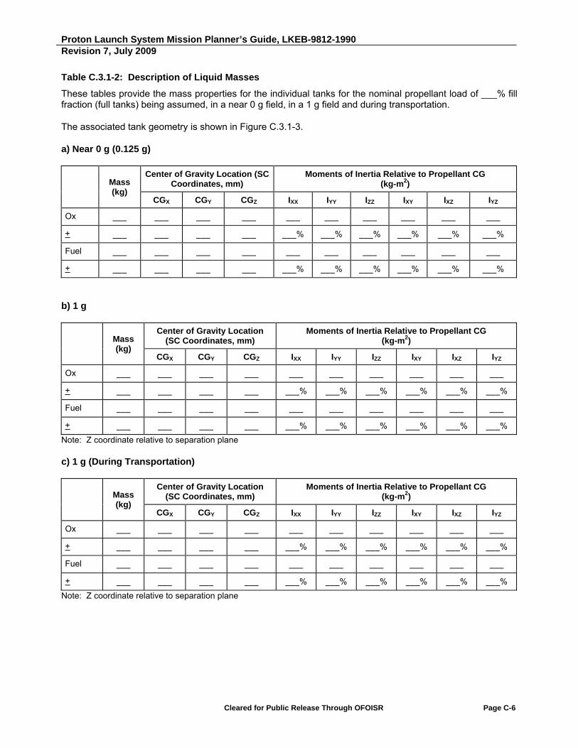
Proton Launch System Mission Planner’s Guide, LKEB-9812-1990 Revision 7, July 2009
Cleared for Public Release Through OFOISR Page C-6
Table C.3.1-2: Description of Liquid Masses
These tables provide the mass properties for the individual tanks for the nominal propellant load of ___% fill fraction (full tanks) being assumed, in a near 0 g field, in a 1 g field and during transportation.
The associated tank geometry is shown in Figure C.3.1-3.
a) Near 0 g (0.125 g)
Mass (kg)
Center of Gravity Location (SC Coordinates, mm)
Moments of Inertia Relative to Propellant CG (kg-m2)
CGX CGY CGZ IXX IYY IZZ IXY IXZ IYZ
Ox ___ ___ ___ ___ ___ ___ ___ ___ ___ ___
+ ___ ___ ___ ___ ___% ___% ___% ___% ___% ___%
Fuel ___ ___ ___ ___ ___ ___ ___ ___ ___ ___
+ ___ ___ ___ ___ ___% ___% ___% ___% ___% ___%
b) 1 g
Mass (kg)
Center of Gravity Location (SC Coordinates, mm)
Moments of Inertia Relative to Propellant CG (kg-m2)
CGX CGY CGZ IXX IYY IZZ IXY IXZ IYZ
Ox ___ ___ ___ ___ ___ ___ ___ ___ ___ ___
+ ___ ___ ___ ___ ___% ___% ___% ___% ___% ___%
Fuel ___ ___ ___ ___ ___ ___ ___ ___ ___ ___
+ ___ ___ ___ ___ ___% ___% ___% ___% ___% ___%
Note: Z coordinate relative to separation plane
c) 1 g (During Transportation)
Mass (kg)
Center of Gravity Location (SC Coordinates, mm)
Moments of Inertia Relative to Propellant CG (kg-m2)
CGX CGY CGZ IXX IYY IZZ IXY IXZ IYZ
Ox ___ ___ ___ ___ ___ ___ ___ ___ ___ ___
+ ___ ___ ___ ___ ___% ___% ___% ___% ___% ___%
Fuel ___ ___ ___ ___ ___ ___ ___ ___ ___ ___
+ ___ ___ ___ ___ ___% ___% ___% ___% ___% ___%
Note: Z coordinate relative to separation plane

Proton Launch System Mission Planner’s Guide, LKEB-9812-1990 Revision 7, July 2009
Cleared for Public Release Through OFOISR Page C-7
Table C.3.1-3: SC Critical Points
SC Critical Points
SC Critical Point
Number
SC Critical Point Coordinates (mm) SC Manufacturing
Tolerance (mm) SC Thermal Isolation
Thickness (mm)
Displacement Transformation
Matrix (DTM) Row Number
Corresponding to SC Critical Points Xsc Ysc Zsc

Proton Launch System Mission Planner’s Guide, LKEB-9812-1990 Revision 7, July 2009
Cleared for Public Release Through OFOISR Page C-8
Figure C.3.1-1: SC Pendulum Model
Pendulum Model Parameters:
1. 0 g
Tank ms (kg) L (m) xs (m) as (m) (%) Mo (kg) Xo (m)
F
O
2. 1 g
Tank ms (kg) L (m) xs (m) as (m) (%) Mo (kg) Xo (m)
F
O
3. Filling Parameters: (t = 20C)
Tank Mass (kg) Level (m) Filling (%) Density (kg/m3) Kinematic Viscosity (m2/s)
F
O
as - Suspension point of the pendulum from the tank bottom (m) L - Length of the pendulum (m) xs - Slosh mass location from the tank bottom (m) ms - Mass of the pendulum (kg) - Damping (%) Mo - Mass of fixed liquid (kg) Xo - Coordinate of mass m0 from the tank bottom (m)

Proton Launch System Mission Planner’s Guide, LKEB-9812-1990 Revision 7, July 2009
Cleared for Public Release Through OFOISR Page C-9
Figure C.3.1-2: Sample SC Slosh Properties During Ballistic Flight and at Separation
);FR()I(Tdt
ldCM
dt
dI i.CT
ii0ggg
2
2
i
i.CTg2
2
gg F)CM(Fdt
ldM
dt
dCM
;m/FAG)a(dt
ad2a
dt
d
dt
adii.СТiii
ii2
i2
)r(rdt
d
dt
ldA i0i02
2
i
)G1(mMM ii
isg ;
i0ii
issg R)G1(mrMCM ;
)R(S)R(S)G1(mII i0i0ii
isg ;
S( i0R ) = S
i
i
i
z
y
x
=
0xy
x0z
yz0
ii
ii
ii
ii0i0 arR ;
)K1(21
)K1(2G
i
ii
; F
r R
k d k V k V r RCT ii i
i i i i i.
0
pr dem p shear t
(see Note 1)
)(
)4
31)(1(1
1
0,5]+ [-0,5;
3
i
i
ii
i
R
HK
r
minimum ;
0
0
1
HK1
Kai
i
ii - )(i
; (see Note 2)
)(
)(dd
i
ii
0i ;
3
i
i
i
i
i
ii R4
H31K11
K
K1rRd ))(()(0i
;
iii
ii
p ddddt
add
i
V ;
ii pi
t Vdt
adV

Proton Launch System Mission Planner’s Guide, LKEB-9812-1990 Revision 7, July 2009
Cleared for Public Release Through OFOISR Page C-10
Notes:
1. kpr = 170229 N/m ; kdеm = 16256 N/m/s ; kshear = 354,3 N/m/s
2. The binary operator
0
0
1
is a matrix that identifies the SC longitudinal axis, that is XSC = 1,0,0, YSC = 0,1,0
and ZSC = 0,0,1.
Conventional Notations:
- SC angular rate vector
l - Vector representing position of origin of SC axes in an inertial frame
C - Vector representing SC CG position relative to SC axes
T - Sum of moments of external forces about origin of SC axes
F - Sum of external forces acting on the SC
ia - Vector representing propellant CG position in ith tank relative to tank center
tiVV ,pi - Radial component and tangential component, respectively, of
dt
ad i , velocity of ith tank’s
propellant CG
Ms, Is - Mass and moment of inertias, respectively, of a dry SC
Ri - Radius of ith tank
sr - Vector representing dry-SC CG position relative to origin of SC axes
mi - ith tank’s propellant mass
ir0 - Vector drawn from axes origin to ith tank’s center
iR0 - Vector representing ith tank’s propellant CG position relative to axes origin
iÀ - ith tank’s inertial acceleration vector
Ki - ith tank’s filling factor (ullage): KI = V filling/ V total
V filling - ith tank’s propellant volume
V total - Total ith tank’s volume
Hi - ith tank’s cylinder length (Hi = 0 corresponds to spherical tank).

Proton Launch System Mission Planner’s Guide, LKEB-9812-1990 Revision 7, July 2009
Cleared for Public Release Through OFOISR Page C-11
Figure C.3.1-3: Propellant Tank Geometry Required Data
Note: TBD data to be supplied by the Customer.

Proton Launch System Mission Planner’s Guide, LKEB-9812-1990 Revision 7, July 2009
Cleared for Public Release Through OFOISR Page C-12
C.3.2 Electrical Interfaces
Item Parameter Units Electrical Connector Confirm type of connectors from SC side
J1 J2
Confirm type of connectors from LV side P1 P2
Confirm location and keying P1 P2
Confirm quantities to be supplied J1 J2 P1 P2
Provide pin locations of SC separation jumper loops P1 pins: P2 pins:
Current flow 20 seconds or less prior to separation milliampere (must be less than 100)
Dry Loop Commands Dry loop commands required? Yes/no Characteristics if yes: # commands Desired pin locations P1 pins: P2 pins: Current Voltage Pulse duration Time during flight
milliampere V ms sec prior to separation
SC Telemetry Processing
LV processing of SC telemetry required? Yes/no Characteristics of if yes: Desired pin locations P1 pins: P2 pins: Voltage Current Data rate
V milliampere Hz
Current Through Umbilicals at Lift-off
Current flow 5 at lift-off. milliampere (must be 0, except jumper circuits)
SC RF Characteristics
Fill in table in attached Table C.3.2-1.
SC Telemetry and Command Antennae used for RF Link Through PLF
Antenna pattern showing antenna origin in SC coordinates, -3 dB bandwidth
Umbilical Wiring Fill out Table C.3.2-2 with pin assignments and desired line characteristics
Mobile Service Tower Can MST be used? Yes/No

Proton Launch System Mission Planner’s Guide, LKEB-9812-1990 Revision 7, July 2009
Cleared for Public Release Through OFOISR Page C-13
Table C.3.2-1: SC RF Characteristics
Description Transmitter Receiver
Carrier Frequency (MHz) ___ ___
Bandwidth at 3 dB (MHz) ___ ___
Bandwidth at 20 dB (MHz) ___ ___
Bandwidth at 60 dB (MHz) ___ ___
Transmission antenna output power (dBW):
max. ___ N/A
nom. ___ N/A
min. ___ N/A
Field flux density on receiving antenna (dBW/m2):
max. N/A ___
nom. N/A ___
min. N/A ___
Polarization ___ ___
Antenna description ___ ___
Antenna location ___ ___
Antenna coverage zone ___ ___
Operating on launch pad? ___ ___
Operating in flight? ___ ___
Ground equipment reception power (dBW):
Destruction limit ___
max. ___ N/A
nom. ___ N/A
min. ___ N/A
Ground equipment output power (dBW):
max. N/A ___
nom. N/A ___
min. N/A ___
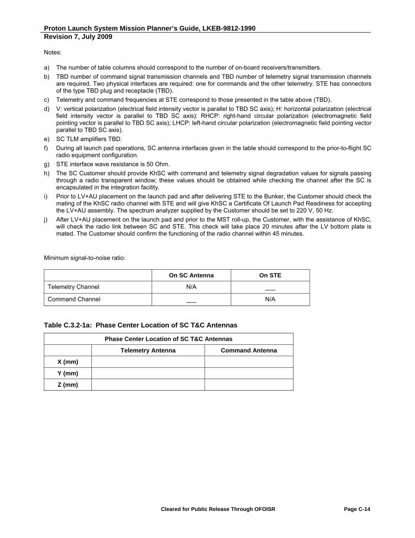
Proton Launch System Mission Planner’s Guide, LKEB-9812-1990 Revision 7, July 2009
Cleared for Public Release Through OFOISR Page C-14
Notes:
a) The number of table columns should correspond to the number of on-board receivers/transmitters.
b) TBD number of command signal transmission channels and TBD number of telemetry signal transmission channels are required. Two physical interfaces are required: one for commands and the other telemetry. STE has connectors of the type TBD plug and receptacle (TBD).
c) Telemetry and command frequencies at STE correspond to those presented in the table above (TBD).
d) V: vertical polarization (electrical field intensity vector is parallel to TBD SC axis); H: horizontal polarization (electrical field intensity vector is parallel to TBD SC axis): RHCP: right-hand circular polarization (electromagnetic field pointing vector is parallel to TBD SC axis); LHCP: left-hand circular polarization (electromagnetic field pointing vector parallel to TBD SC axis).
e) SC TLM amplifiers TBD.
f) During all launch pad operations, SC antenna interfaces given in the table should correspond to the prior-to-flight SC radio equipment configuration.
g) STE interface wave resistance is 50 Ohm.
h) The SC Customer should provide KhSC with command and telemetry signal degradation values for signals passing through a radio transparent window; these values should be obtained while checking the channel after the SC is encapsulated in the integration facility.
i) Prior to LV+AU placement on the launch pad and after delivering STE to the Bunker, the Customer should check the mating of the KhSC radio channel with STE and will give KhSC a Certificate Of Launch Pad Readiness for accepting the LV+AU assembly. The spectrum analyzer supplied by the Customer should be set to 220 V, 50 Hz.
j) After LV+AU placement on the launch pad and prior to the MST roll-up, the Customer, with the assistance of KhSC, will check the radio link between SC and STE. This check will take place 20 minutes after the LV bottom plate is mated. The Customer should confirm the functioning of the radio channel within 45 minutes.
Minimum signal-to-noise ratio:
On SC Antenna On STE
Telemetry Channel N/A ___
Command Channel ___ N/A
Table C.3.2-1a: Phase Center Location of SC T&C Antennas
Phase Center Location of SC T&C Antennas
Telemetry Antenna Command Antenna
X (mm)
Y (mm)
Z (mm)
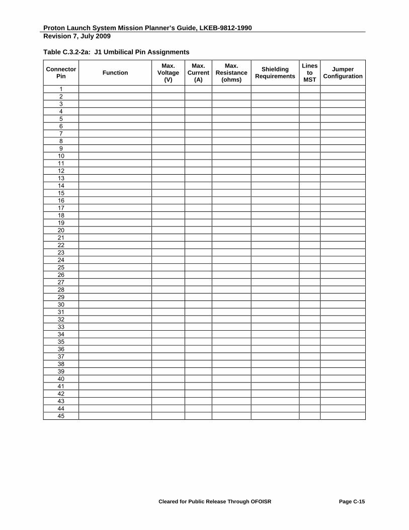
Proton Launch System Mission Planner’s Guide, LKEB-9812-1990 Revision 7, July 2009
Cleared for Public Release Through OFOISR Page C-15
Table C.3.2-2a: J1 Umbilical Pin Assignments
Connector Pin
Function Max.
Voltage (V)
Max. Current
(A)
Max. Resistance
(ohms)
Shielding Requirements
Lines to
MST
Jumper Configuration
1 2 3 4 5 6 7 8 9
10 11 12 13 14 15 16 17 18 19 20 21 22 23 24 25 26 27 28 29 30 31 32 33 34 35 36 37 38 39 40 41 42 43 44 45

Proton Launch System Mission Planner’s Guide, LKEB-9812-1990 Revision 7, July 2009
Cleared for Public Release Through OFOISR Page C-16
Table C.3.2-2a: J1 Umbilical Pin Assignments (Continued)
Connector Pin
Function Max.
Voltage (V)
Max. Current
(A)
Max. Resistance
(ohms)
Shielding Requirements
Lines to
MST
Jumper Configuration
46 47 48 49 50 51 52 53 54 55 56 57 58 59 60 61
Note: Indicated resistance values are from P1/P2 IFD connection to the KhSC/SC contractor EGSE interface in the Vault room (or on the MST for designated circuits).

Proton Launch System Mission Planner’s Guide, LKEB-9812-1990 Revision 7, July 2009
Cleared for Public Release Through OFOISR Page C-17
Table C.3.2.2b: J2 Umbilical Pin Assignments
Connector Pin
Function Max.
Voltage (V)
Max. Current
(A)
Max. Resistance
(ohms)
Shielding Requirements
Lines to
MST
Jumper Configuration
1 2 3 4 5 6 7 8 9
10 11 12 13 14 15 16 17 18 19 20 21 22 23 24 25 26 27 28 29 30 31 32 33 34 35 36 37 38 39 40 41 42 43 44 45
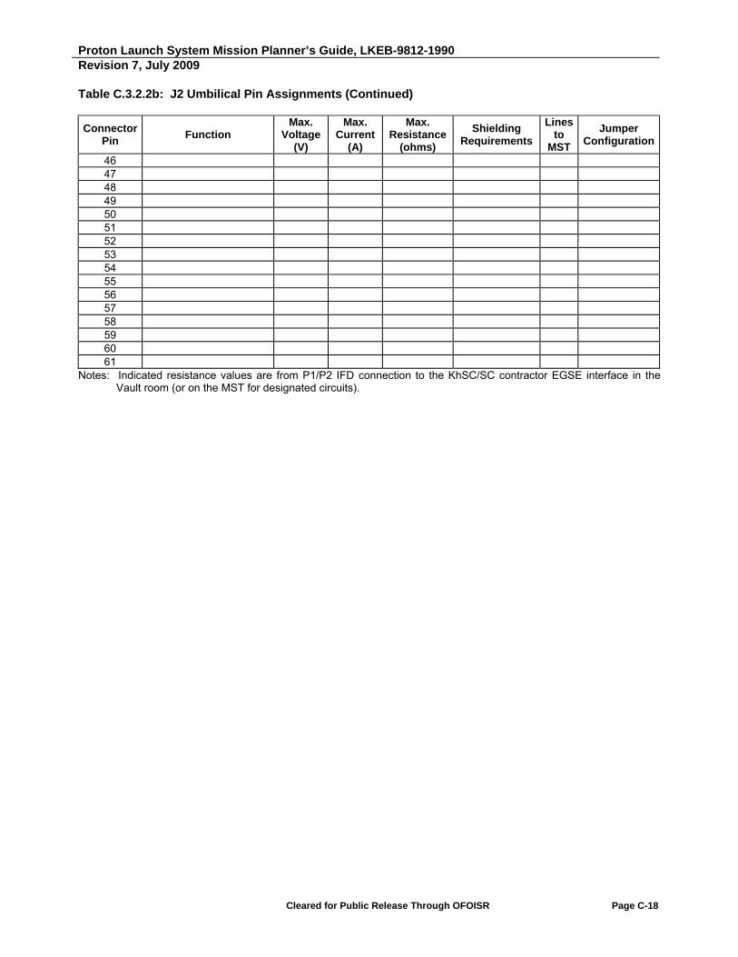
Proton Launch System Mission Planner’s Guide, LKEB-9812-1990 Revision 7, July 2009
Cleared for Public Release Through OFOISR Page C-18
Table C.3.2.2b: J2 Umbilical Pin Assignments (Continued)
Connector Pin
Function Max.
Voltage (V)
Max. Current
(A)
Max. Resistance
(ohms)
Shielding Requirements
Lines to
MST
Jumper Configuration
46 47 48 49 50 51 52 53 54 55 56 57 58 59 60 61
Notes: Indicated resistance values are from P1/P2 IFD connection to the KhSC/SC contractor EGSE interface in the Vault room (or on the MST for designated circuits).

Proton Launch System Mission Planner’s Guide, LKEB-9812-1990 Revision 7, July 2009
Cleared for Public Release Through OFOISR Page C-19
C.3.3 Environmental Interfaces
Item Parameter Units
Thermal Requirements Provide any particular ground thermal requirements.
Provide any particular thermal requirements during ascent or parking orbit.
Provide any particular thermal requirements during transfer orbit including Sun Angle vs. Time.
Provide any particular thermal requirements during final injection orbit.
Venting Analysis Provide archimedes volume of SC in launch configuration (for venting analysis).
SC Testing Provide confirmation of compliance with Planner’s Guide test requirements for acoustic, sine, static testing and for the fitcheck/shock test.
EMC Provide confirmation of compliance with EM susceptibility curve for ILV in Planner’s Guide.
Provide confirmation of acceptability of integrated ILV radiated emissions curve in Planner’s Guide.
Humidity Provide humidity requirements for ground transportation.
Provide humidity requirements for processing facility.

Proton Launch System Mission Planner’s Guide, LKEB-9812-1990 Revision 7, July 2009
Cleared for Public Release Through OFOISR Page C-20
C.3.4 Flight Design
Item Parameter Units
Parking Orbit Define thermal conditioning maneuvers required.
Define sun angle constraints.
Intermediate Orbit Define thermal conditioning maneuvers required.
Define sun angle constraints.
Transfer Orbit Define thermal conditioning maneuvers required.
Define sun angle constraints.
Injection Orbit SC Separated mass
Orbital parameters:
Perigee altitude
Apogee altitude
Inclination
Argument of perigee
kg
km
km
degrees
degrees
SC Launch Windows Define SC constraints that affect LV launch window.
Provide target launch date.
Provide launch window at perigee passage or at SC separation for one year covering the contractual launch date. Include launch window opening and closing times in GMT for each day.
Separation Define type of separation: 3 axis stabilized, spinning or transverse spin.
Define desired separation attitude with a diagram showing the pointing vector in SC coordinates and the pointing vector relative to the relative right ascension and declination as defined in this PMPG.
Define desired spin rate about each SC axis.
Define desired spin rate tolerance about each SC axis.
degrees
degrees
Define desired separation velocity. m/s

Proton Launch System Mission Planner’s Guide, LKEB-9812-1990 Revision 7, July 2009
Cleared for Public Release Through OFOISR Page C-21
C.3.5 Operations
Item Parameter Units
EGSE Fill out table in Table C.3.5-1 for all EGSE to be used at launch site.
Fluid and Gases Fill out table in Table C.3.5-2 for quantities and types of fluids and gases.
Contamination Control Provide any special requirements.
Campaign Support Provide list of support required in each area (if non-standard):
Building 92A-50
Hall 102
Hall 101
Hall 111
Hall 103A
Control Room 4102
Hall 103
Offices
Launch Complex 200
Bunker
Vault
Pad 39
Launch Complex 81
Bunker
Vault
Pad 24
Breeze M Fueling Area
Hotel Area
Transportation Provide description of all items including propellant to be shipped including:
Item name
Quantity
Weight
Tie down method
Storage requirements
kg

Proton Launch System Mission Planner’s Guide, LKEB-9812-1990 Revision 7, July 2009
Cleared for Public Release Through OFOISR Page C-22
Item Parameter Units
Handling Provide description of items which require physical handling at the launch site including:
Equipment name/location
Dimensions
Weight
CG
Handling method
m kg m
Communications Define number and type of international lines required.
If multiplexer provided, provide characteristics of and desired location.
Provide locations of all intersite data transmissions, including data type and rate and interface (analog modem, V.35 or RS232 interface).
Provide requirements for hardline data transmission between Area 81 or Area 200 Vault and Bunker and Building 92A-50.
Ground Electrical Interfaces
Provide block diagrams of desired umbilical interfaces between SC and EGSE while being processed and while on the pad.
Feedthroughs Provide description of feedthroughs required between Control Room 4102 of Building 92A-50 and Hall 103A, including:
Feedthrough designation
Cable designation
Cable connector diameter
Cable diameter
mm
mm
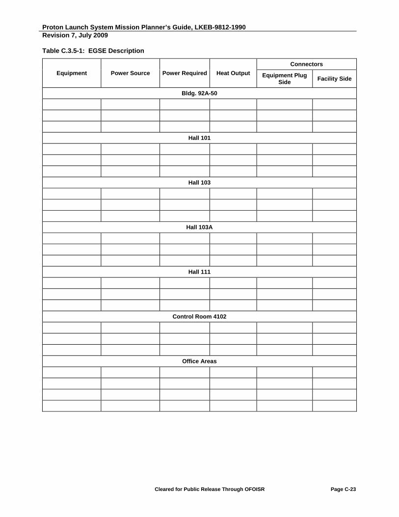
Proton Launch System Mission Planner’s Guide, LKEB-9812-1990 Revision 7, July 2009
Cleared for Public Release Through OFOISR Page C-23
Table C.3.5-1: EGSE Description
Equipment Power Source Power Required Heat Output
Connectors
Equipment Plug Side
Facility Side
Bldg. 92A-50
Hall 101
Hall 103
Hall 103A
Hall 111
Control Room 4102
Office Areas

Proton Launch System Mission Planner’s Guide, LKEB-9812-1990 Revision 7, July 2009
Cleared for Public Release Through OFOISR Page C-24
Table C.3.5-1: EGSE Description (Continued)
Equipment Power Source Power Required Heat Output
Connectors
Equipment Plug Side
Facility Side
Launch Complex 81 or 200
Bunker (Room 250)
Bunker (Room 251)
Bunker (Room 246)
Vault (Room 64, 76 or 79)
Breeze M Fueling Station

Proton Launch System Mission Planner’s Guide, LKEB-9812-1990 Revision 7, July 2009
Cleared for Public Release Through OFOISR Page C-25
Table C.3.5-2: Fluids/Gases Requirements
Name Conditions Supplied By Location of Use
Compressed air for breathing (SCAPE)
See Proton Launch Campaign Guide for maximum available
KhSC/ILS Fueling Hall
Distilled water See Proton Launch Campaign Guide for maximum available.
KhSC/ILS Processing Hall Fueling Hall
Demineralized water See Proton Launch Campaign Guide for maximum available
KhSC/ILS Decontamination Area
Nitrogen GOST-92-93-74, Technical Grade 1
See Proton Launch Campaign Guide for maximum available
KhSC/ILS Decontamination Area
Nitrogen GOST-92-93-74, Technical Grade 1
See Proton Launch Campaign Guide for maximum available
KhSC/ILS Fueling Hall
Liquid Nitrogen (LN2) TBD liters KhSC/ILS Fueling Hall
Gaseous He (GHe) per spec MIL-P-27407 Type 1, Grade A
TBD K-bottles high pressure (400 bar) TBD K-bottles low pressure (135 bar)
SC contractor
Fueling Hall
MMH TBD cylinders - total weight each TBD kg maximum, TBD kg maximum propellant weight
SC contractor
Fueling Hall
Nitrogen TBD SC contractor
Fueling Hall
Nitrogen Tetroxide (NTO) TBD cylinders - total weight each TBD kg maximum, TBD kg maximum propellant weight
SC contractor
Fueling Hall
Shop Air See Proton Launch Campaign Guide for maximum available
KhSC/ILS Fueling Hall
Ethyl Alcohol See Proton Launch Campaign Guide for maximum available
KhSC/ILS Fueling Hall
Service Water See Proton Launch Campaign Guide for maximum available
KhSC/ILS Fueling Hall
Grade “Extra” or Highest Grade GOST 18300-87 Ethyl Alcohol
See Proton Launch Campaign Guide for maximum available
KhSC/ILS Fueling Hall
Freon TBD SC contractor
Argon TBD SC contractor
IPA TBD SC contractor
Note: TBD data to be supplied by the SC contractor.

Intentionally Blank

Proton Launch System Mission Planner’s Guide
APPENDIX D
Adapter Systems


Proton Launch System Mission Planner’s Guide, LKEB-9812-1990 Revision 7, July 2009
Cleared for Public Release Through OFOISR Page D-1
D. ADAPTER SYSTEMS
This appendix presents information on Adapter Systems (AS) that may be used for commercial launches with the Breeze M. Currently, the following five adapter systems are available:
Table D.1 Payload Adapter Systems
Adapter System Type Section
937VB-1168 D.1
1194VX-1000 (1194VS-1000) D.2
1666V-1000 D.3
1664HP-1000 D.4
Information on the SC/AS mechanical interface, the structure's load-bearing capacity, and the characteristics of the AS interface ring are presented in Sections D.1 through D.4.
The typical SC/AS electrical interface is described in Section 4.2.
Proton Launch System Mission Planner’s Guide, LKEB-9812-1990 Revision 7, July 2009
Cleared for Public Release Through OFOISR Page D-2
D.1 ADAPTER SYSTEM 937VB-1168
D.1.1 Adapter System Description
Adapter system 937VB-1168 comprises a frame, the 937VB separation system (developed by RUAG Aerospace Sweden AB), telemetry and ground measurement system sensors, thermal insulation, and electrical cables.
The AS mechanical interface to the SC comprises an AS interface ring, a clampband with 937VB separation system push springs, separation verification sensors, umbilical electrical connectors (as the mechanical part of the electrical interface), and a SC purge fitting (which is installed depending on the specific SC).
The AS frame is conical and constructed of three parts.
The top part is a metal ring developed by RUAG Aerospace Sweden AB, intended for mating to the SC. The 937VB separation system and the separation verification sensor are mounted on it. Interface rings manufactured by other companies may be mounted instead, together with the 937VS or 937LPSU separation systems, which are described in Section 4.1.5. One or two scribe marks should be engraved on the side surface of the AS interface ring to control the clocking of the adapter with respect to the SC interface. Angular location of the adapter scribe marks should be the same as for the SC interface ring.
The middle part is a metal spacer designed by KhSC. The spacer holds two brackets to secure the umbilical electrical connectors.
The bottom part is a carbon composite spacer. It is of typical design and is also used in the 1194VX-1000 and 1194VS-1000 adapter systems.
Drawings of the 937VB-1168 AS, which include the mechanical interface, are shown in Figures D.1.1-1a through D.1.1-1e.
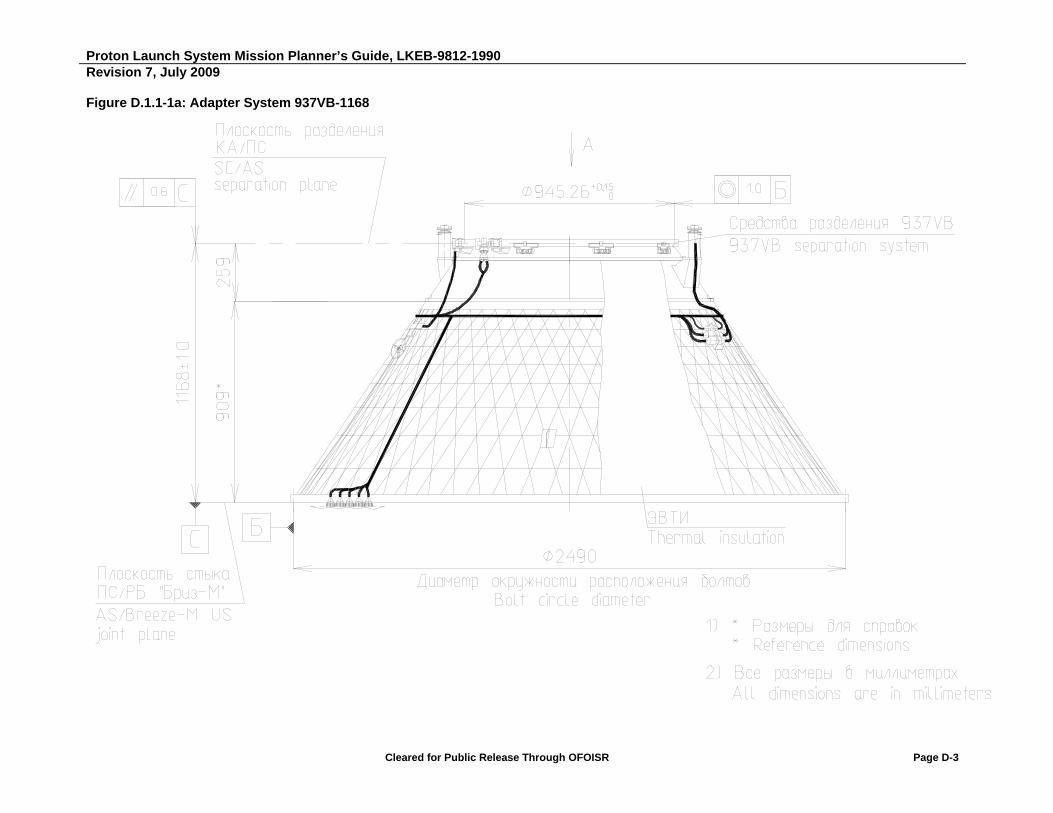
Proton Launch System Mission Planner’s Guide, LKEB-9812-1990 Revision 7, July 2009
Cleared for Public Release Through OFOISR Page D-3
Figure D.1.1-1a: Adapter System 937VB-1168
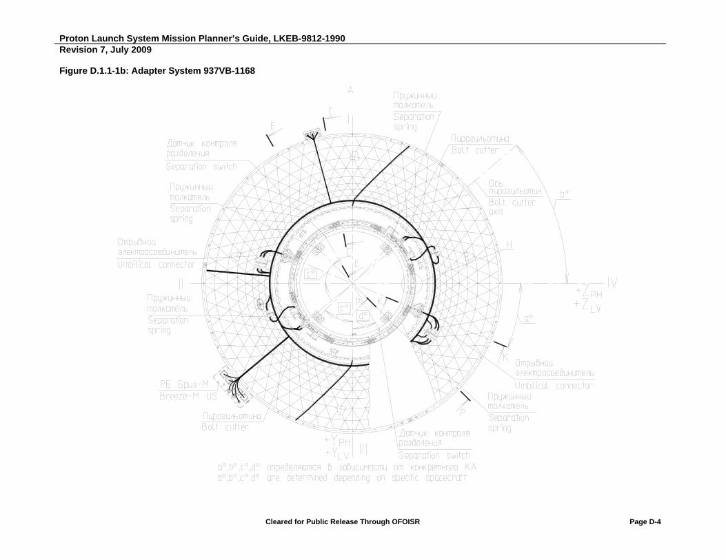
Proton Launch System Mission Planner’s Guide, LKEB-9812-1990 Revision 7, July 2009
Cleared for Public Release Through OFOISR Page D-4
Figure D.1.1-1b: Adapter System 937VB-1168
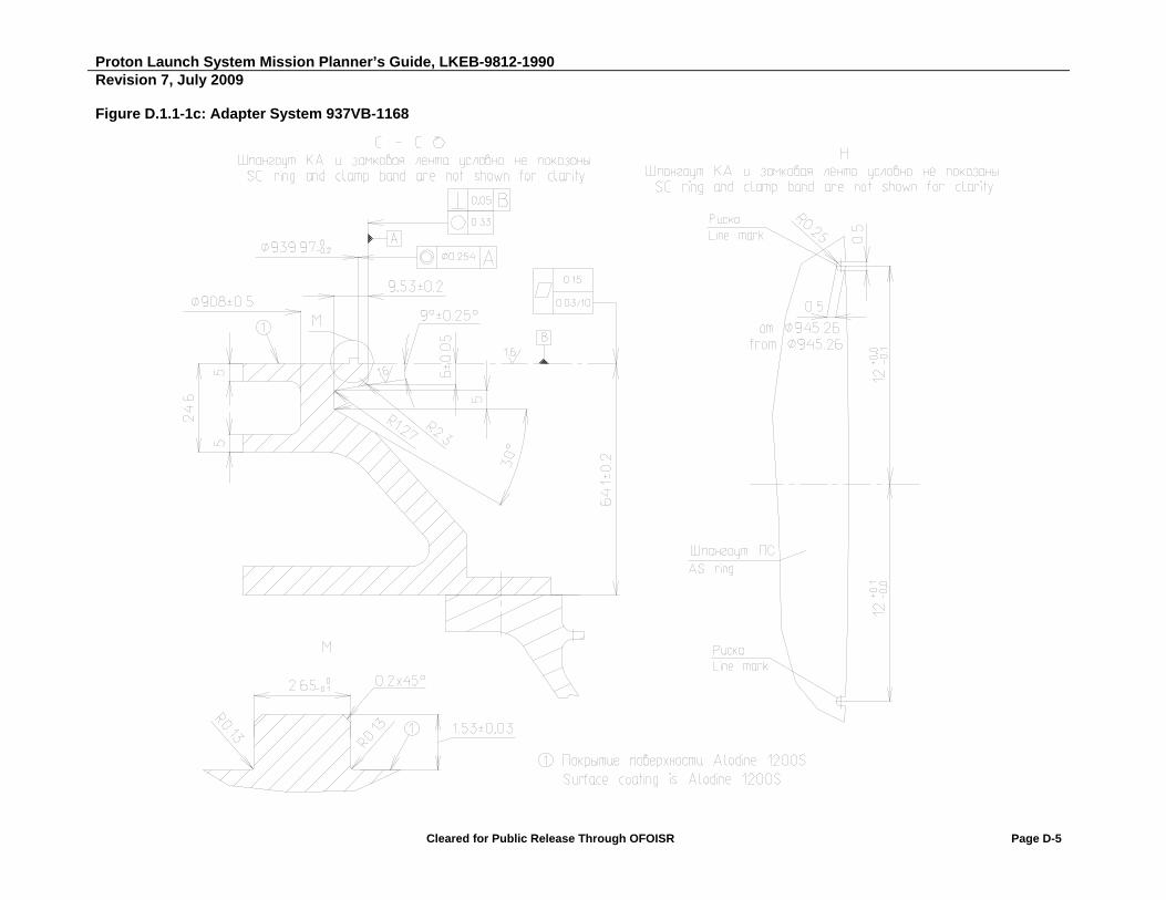
Proton Launch System Mission Planner’s Guide, LKEB-9812-1990 Revision 7, July 2009
Cleared for Public Release Through OFOISR Page D-5
Figure D.1.1-1c: Adapter System 937VB-1168

Proton Launch System Mission Planner’s Guide, LKEB-9812-1990 Revision 7, July 2009
Cleared for Public Release Through OFOISR Page D-6
Figure D.1.1-1d: Adapter System 937VB-1168

Proton Launch System Mission Planner’s Guide, LKEB-9812-1990 Revision 7, July 2009
Cleared for Public Release Through OFOISR Page D-7
Figure D.1.1-1e: Adapter system 937VB-1168

Proton Launch System Mission Planner’s Guide, LKEB-9812-1990 Revision 7, July 2009
Cleared for Public Release Through OFOISR Page D-8
D.1.2 Load-Bearing Capability
The load-bearing capability of the AS structure is based on the allowable load determined after testing. The AS will hold down a SC having a maximum mass of 3740 kg, whose CG is located 1.375 m above the separation plane. This structural load-bearing capability is determined for standard interface ring characteristics, specified in Table D.1.3, and geometrical parameters, specified in Figure D.1.1-1c. Quasi-static accelerations used in the calculation are shown in Section 3.4.1. It is assumed that the circumferential linear load is uniformly distributed in the separation plane. A potentially non-uniform linear load will reduce the allowable distance to the CG for a SC of the given mass.
The shown values of load-bearing capacity should be used only for preliminary evaluation of AS strength. During the early phase of SC integration with the LV, it will be necessary to perform a CLA to verify strength when loading the AS structure and the separation system.
D.1.3 Interface Ring Characteristics
The SC and AS interface rings and the separation system are designed to transfer loads from the SC to the AS during ground operations and in flight. The outer contours of the rings are designed to mate with the separation system clampband. A description of the SC and AS interface ring cross sections and materials are shown in Table D.1.3-1. Figure D.1.3-1 shows the reference frame axes used to analyze the characteristics of the interface ring geometrical cross sections.
Table D.1.3-1: Characteristics of SC and AS Interface Rings
Ring Characteristic SC Ring AS Ring
Height of effective cross section (L) 25 mm 25 mm
Cross-section area (A) 466 mm2 ± 10% 579 mm2
Moment of inertia (IXX) 44629 mm4 ± 10% 51550 mm4
Moment of inertia (IYY) 18802 mm4 ± 10% 42350 mm4
Modulus of elasticity (E) 70.3 x 10³ MPa -
Figure D.1.3-1: SC and AS Interface Ring Cross Sections

Proton Launch System Mission Planner’s Guide, LKEB-9812-1990 Revision 7, July 2009
Cleared for Public Release Through OFOISR Page D-9
D.2 ADAPTER SYSTEM 1194VX-1000 (1194VS-1000)
D.2.1 Adapter System Description
Adapter system 1194VX-1000 comprises a frame, the 1194VX separation system (developed by RUAG Aerospace Sweden AB), telemetry and ground measurement system sensors, thermal insulation, and electrical cables.
The makeup of adapter system 1194VS-1000 is the same, except that the 1194VS separation system (developed by RUAG Aerospace Sweden AB) is used instead of the 1194VX separation system.
The AS mechanical interface to the SC comprises an AS interface ring, a clampband with 1194VX (1194VS) separation system push springs, separation verification sensors, umbilical electrical connectors (as the mechanical part of the electrical interface), and a SC purge fitting (which is installed depending on the specific SC).
The AS frame is conical and constructed of two parts.
The top part is a metal ring that includes a SC interface ring. The 1194VX (11994VS) separation system and two separation verification sensors are mounted on it. The 1194LPSU-1000 separation system, which is described in Section 4.1.5, may also be mounted on this ring. One or two scribe marks should be engraved on the side surface of the AS interface ring to control the clocking of the adapter with respect to the SC interface. Angular location of the adapter scribe marks should be the same as for the SC interface ring.
The bottom part is a carbon composite spacer. It is of typical design and is also used in the 937VB-1168 adapter system. Two brackets with umbilical electrical connectors are mounted on the bottom part of the AS.
Drawings of the 1194VX-1000 AS, which include the mechanical interface, are shown in Figures D.2.1-1a through D.2.1-1e. Figure D.2.1-1b shows a view of the 1194VX-1000 adapter system; Figure D.2.1-1c, of the 1194VS-1000 adapter system. The remaining drawings are identical for both adapter systems.

Proton Launch System Mission Planner’s Guide, LKEB-9812-1990 Revision 7, July 2009
Cleared for Public Release Through OFOISR Page D-10
Figure D.2.1-1a: Adapter System 1194VX-1000 (1194VS-1000)
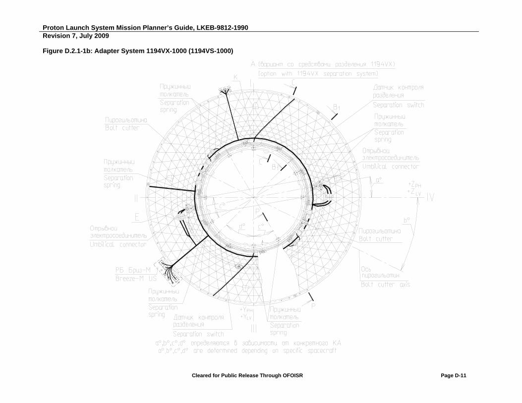
Proton Launch System Mission Planner’s Guide, LKEB-9812-1990 Revision 7, July 2009
Cleared for Public Release Through OFOISR Page D-11
Figure D.2.1-1b: Adapter System 1194VX-1000 (1194VS-1000)

Proton Launch System Mission Planner’s Guide, LKEB-9812-1990 Revision 7, July 2009
Cleared for Public Release Through OFOISR Page D-12
Figure D.2.1-1c: Adapter System 1194VX-1000 (1194VS-1000)
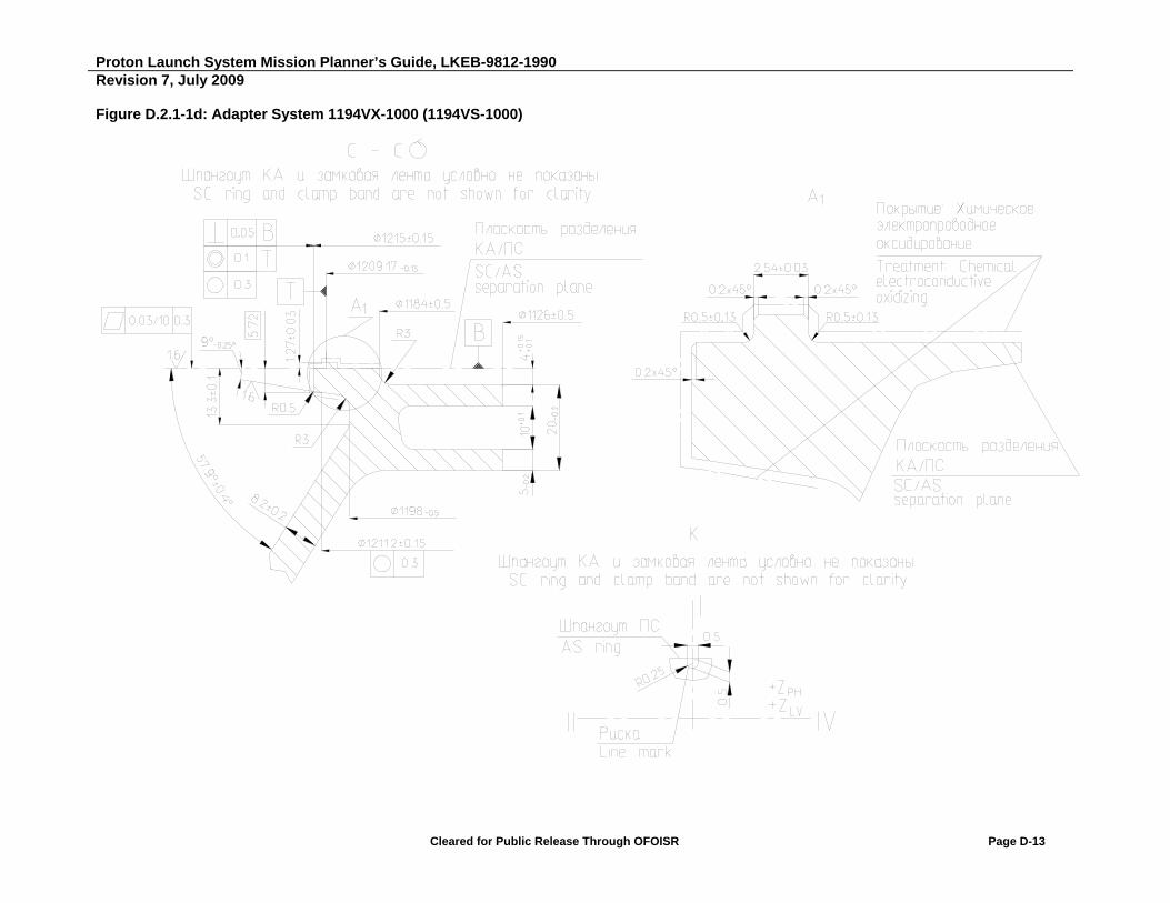
Proton Launch System Mission Planner’s Guide, LKEB-9812-1990 Revision 7, July 2009
Cleared for Public Release Through OFOISR Page D-13
Figure D.2.1-1d: Adapter System 1194VX-1000 (1194VS-1000)
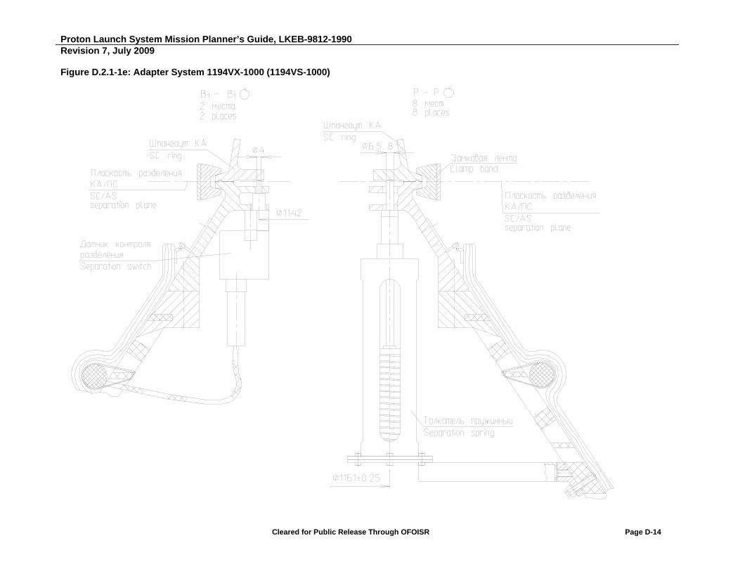
Proton Launch System Mission Planner’s Guide, LKEB-9812-1990 Revision 7, July 2009
Cleared for Public Release Through OFOISR Page D-14
Figure D.2.1-1e: Adapter System 1194VX-1000 (1194VS-1000)

Proton Launch System Mission Planner’s Guide, LKEB-9812-1990 Revision 7, July 2009
Cleared for Public Release Through OFOISR Page D-15
Figure D.2.1-1f: Adapter System 1194VX-1000 (1194VS-1000)

Proton Launch System Mission Planner’s Guide, LKEB-9812-1990 Revision 7, July 2009
Cleared for Public Release Through OFOISR Page D-16
D.2.2 Load-Bearing Capability
The load-bearing capability of the AS structure is based on the allowable load determined after testing. The maximum allowable longitudinal position of the SC CG relative to the separation plane is shown in Fig. D.2.2-1 as a function of SC mass for various nominal values of clampband tension when using the 1194VX-1000 and 1194VS-1000 adapter systems. This position of the SC CG is determined for standard interface ring characteristics, specified in Table D.2.3-1, and geometrical parameters, specified in Figure D.2.1-1d. Quasi-static accelerations used in the calculation are shown in Section 3.4.1. It is assumed that the circumferential linear load is uniformly distributed in the separation plane. A potentially non-uniform linear load will reduce the allowable distance to the CG for a SC of the given mass.
The shown values of load-bearing capacity should be used only for preliminary evaluation of AS strength. During the early phase of SC integration with the LV, it will be necessary to perform a CLA to verify strength when loading the AS structure and the separation system.
Figure D.2.2-1: Load-bearing Capability of 1194VX-1000 and 1194VS-1000 Adapter System
0
1
2
3
4
5
6
7
3000 3500 4000 4500 5000 5500 6000 6500 7000 7500
Lo
ng
itu
din
al O
ffse
t of
SC
CG
fro
m
SC
Sep
arat
ion
Pla
ne
(m)
SC Mass (kg)
Clampband tension 35 kN (1194VX)
Clampband tension 40 kN (1194VX)
Clampband tension 54 kN (1194VS)
SC Mass (kg)
Allowable CG Offset Relative to SC Separation Plane (m)
35 kN Tension (1194VX)
40 kN Tension (1194VX)
54 kN Tension (1194VS)
3000 4.65 5.24 6.38 3500 4.00 4.50 5.48 4000 3.51 3.95 4.80 4500 3.12 3.51 4.28 5000 2.82 3.17 3.86 5500 2.57 2.89 3.51 6000 2.31 2.60 3.18 6500 2.13 2.40 2.93 7000 1.98 2.23 2.72 7500 1.85 2.09 2.54
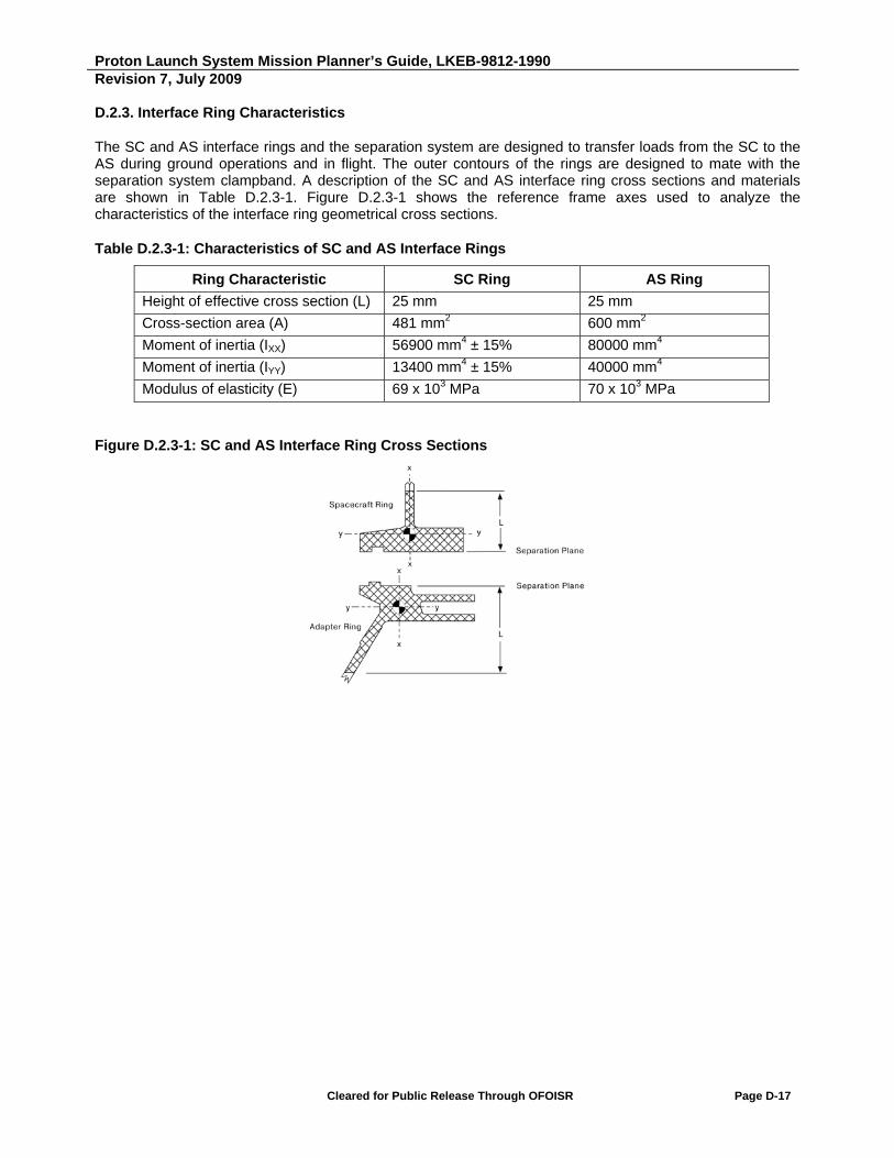
Proton Launch System Mission Planner’s Guide, LKEB-9812-1990 Revision 7, July 2009
Cleared for Public Release Through OFOISR Page D-17
D.2.3. Interface Ring Characteristics
The SC and AS interface rings and the separation system are designed to transfer loads from the SC to the AS during ground operations and in flight. The outer contours of the rings are designed to mate with the separation system clampband. A description of the SC and AS interface ring cross sections and materials are shown in Table D.2.3-1. Figure D.2.3-1 shows the reference frame axes used to analyze the characteristics of the interface ring geometrical cross sections.
Table D.2.3-1: Characteristics of SC and AS Interface Rings
Ring Characteristic SC Ring AS Ring
Height of effective cross section (L) 25 mm 25 mm
Cross-section area (A) 481 mm2 600 mm2
Moment of inertia (IXX) 56900 mm4 ± 15% 80000 mm4
Moment of inertia (IYY) 13400 mm4 ± 15% 40000 mm4
Modulus of elasticity (E) 69 x 103 MPa 70 x 103 MPa
Figure D.2.3-1: SC and AS Interface Ring Cross Sections
Proton Launch System Mission Planner’s Guide, LKEB-9812-1990 Revision 7, July 2009
Cleared for Public Release Through OFOISR Page D-18
D.3 ADAPTER SYSTEM 1666V-1000
D.3.1 Adapter System Description
Adapter system 1666V-1000 comprises a frame, the 1666V separation system (developed by RUAG Aerospace Sweden AB), telemetry and ground measurement system sensors, thermal insulation, and electrical cables.
The AS mechanical interface to the SC comprises the AS interface ring, a clampband with 1666V separation system push springs, separation verification sensors, umbilical electrical connectors (as the mechanical part of the electrical interface), and a SC purge fitting (which is installed depending on the specific SC).
The AS framework is conical and constructed of two parts.
The upper part is a metal spacer developed by RUAG, which includes an interface SC interface ring. The 1666V separation system, two separation verification sensors, and umbilical electrical connectors are mounted on the spacer.
The lower part is a metal spacer designed by KhSC.
Drawings of the 1666V AS, which include the mechanical interface, are shown in Figures D.3.1-1a through D.3.1-1e.

Proton Launch System Mission Planner’s Guide, LKEB-9812-1990 Revision 7, July 2009
Cleared for Public Release Through OFOISR Page D-19
Figure D.3.3-1a: Adapter System 1666V-1000
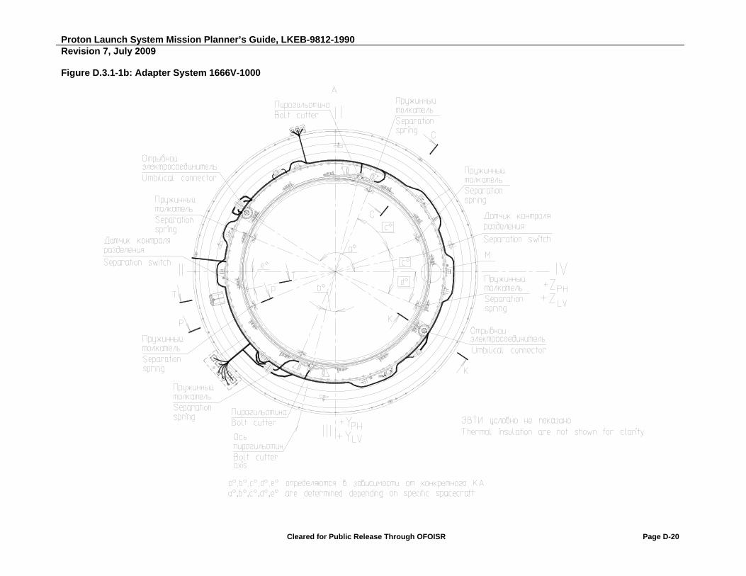
Proton Launch System Mission Planner’s Guide, LKEB-9812-1990 Revision 7, July 2009
Cleared for Public Release Through OFOISR Page D-20
Figure D.3.1-1b: Adapter System 1666V-1000
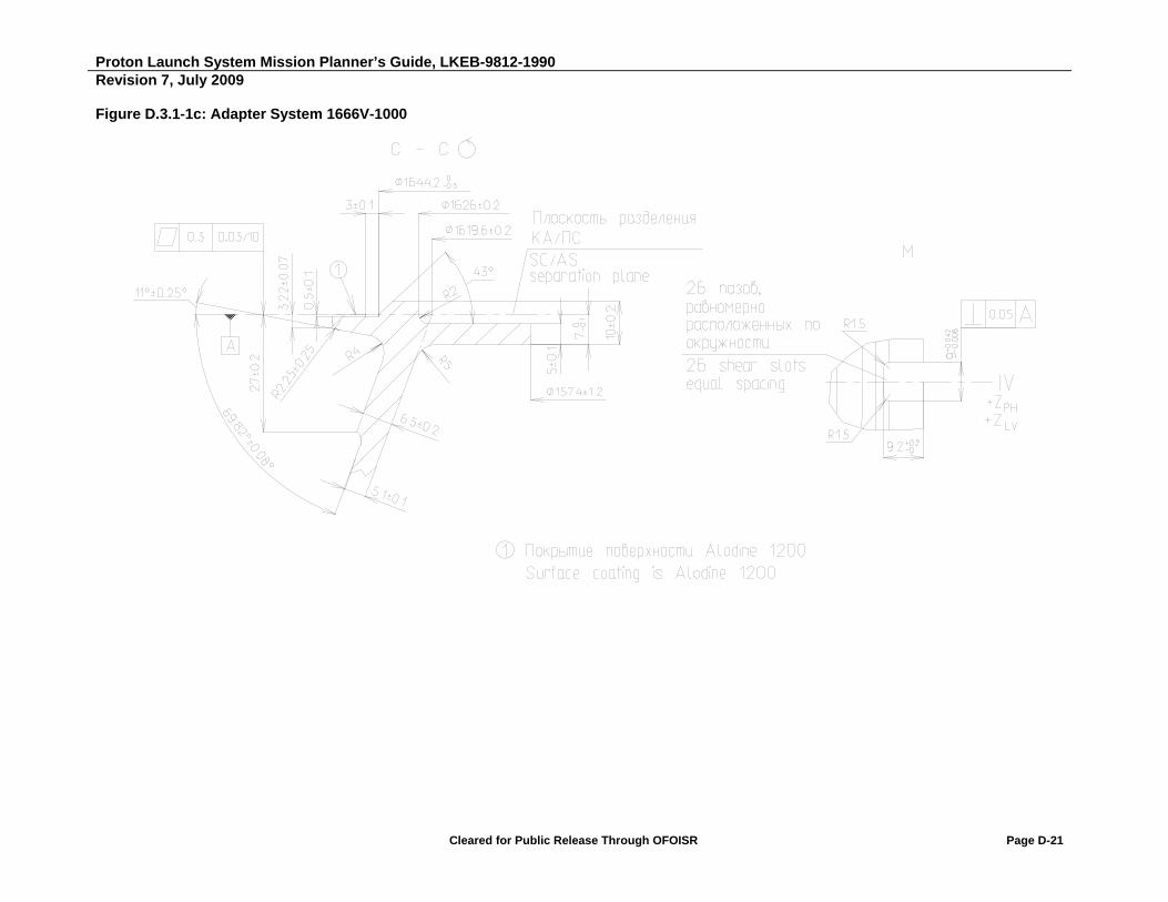
Proton Launch System Mission Planner’s Guide, LKEB-9812-1990 Revision 7, July 2009
Cleared for Public Release Through OFOISR Page D-21
Figure D.3.1-1c: Adapter System 1666V-1000

Proton Launch System Mission Planner’s Guide, LKEB-9812-1990 Revision 7, July 2009
Cleared for Public Release Through OFOISR Page D-22
Figure D.3.1-1d: Adapter System 1666V-1000

Proton Launch System Mission Planner’s Guide, LKEB-9812-1990 Revision 7, July 2009
Cleared for Public Release Through OFOISR Page D-23
Figure D.3.1-1e: Adapter System 1666V-1000

Proton Launch System Mission Planner’s Guide, LKEB-9812-1990 Revision 7, July 2009
Cleared for Public Release Through OFOISR Page D-24
D.3.2 Load-Bearing Capability of the Structure
The load-bearing capability of the AS structure is based on the allowable load determined after testing. The maximum allowable longitudinal position of the SC CG relative to the separation plane is shown in Figure D.3.2-1 as a function of SC mass for a nominal clampband tension of 30 kN when using the 1666V-1000 adapter system. This position of the SC CG is determined for standard interface ring characteristics, specified in Table D.3.3-1, and geometrical parameters, specified in Figure D.3.1-1c. Quasi-static accelerations used in the calculation are shown in Section 3.4.1. It is assumed that the circumferential linear load is uniformly distributed in the separation plane. A potentially non-uniform linear load will reduce the allowable distance to the CG for a SC of the given mass.
The shown values of load-bearing capacity should be used only for preliminary evaluation of AS strength. During the early phase of SC integration with the LV, it will be necessary to perform a CLA to verify strength when loading the AS structure and the separation system.
Figure D.3.2-1: Load-bearing Capability of 1666V-1000 Adapter System
0
1
2
3
4
2000 2200 2400 2600 2800 3000 3200 3400 3600 3800 4000 4200 4400
Lo
ng
itu
din
al O
ffse
t of
SC
CG
fro
m
SC
Sep
arat
ion
Pla
ne
(m)
SC Mass (kg)
Clampband tension 30 kN
SC Mass (kg)
Allowable CG Offset Relative to SC Separation
Plane (m) 30 kN Tension
2000 3.30 2200 3.00 2400 2.75 2600 2.45 2800 2.20 3000 2.00 3200 1.80 3400 1.60 3600 1.45 3800 1.30 4000 1.20 4200 1.10 4400 1.00
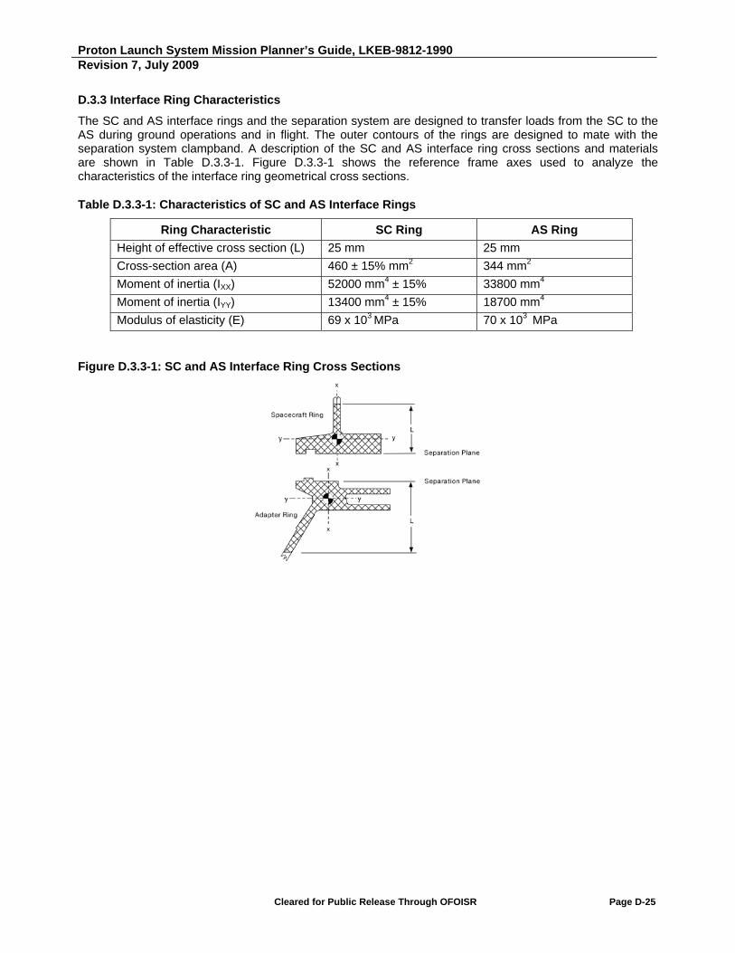
Proton Launch System Mission Planner’s Guide, LKEB-9812-1990 Revision 7, July 2009
Cleared for Public Release Through OFOISR Page D-25
D.3.3 Interface Ring Characteristics
The SC and AS interface rings and the separation system are designed to transfer loads from the SC to the AS during ground operations and in flight. The outer contours of the rings are designed to mate with the separation system clampband. A description of the SC and AS interface ring cross sections and materials are shown in Table D.3.3-1. Figure D.3.3-1 shows the reference frame axes used to analyze the characteristics of the interface ring geometrical cross sections.
Table D.3.3-1: Characteristics of SC and AS Interface Rings
Ring Characteristic SC Ring AS Ring
Height of effective cross section (L) 25 mm 25 mm
Cross-section area (A) 460 ± 15% mm2 344 mm2
Moment of inertia (IXX) 52000 mm4 ± 15% 33800 mm4
Moment of inertia (IYY) 13400 mm4 ± 15% 18700 mm4
Modulus of elasticity (E) 69 x 103 MPa 70 x 103 MPa
Figure D.3.3-1: SC and AS Interface Ring Cross Sections

Proton Launch System Mission Planner’s Guide, LKEB-9812-1990 Revision 7, July 2009
Cleared for Public Release Through OFOISR Page D-26
D.4 ADAPTER SYSTEM 1664HP-1000
D.4.1 Adapter System Description
Adapter system 1664HP-1000 comprises a frame, the 1664HP separation system (developed by KhSC), telemetry and ground measurement system sensors, thermal insulation, and electrical cables.
The AS mechanical interface to the SC comprises an AS interface ring, four latches and push springs for the 1664HP separation system, separation verification sensors, umbilical electrical connectors (as the mechanical part of the electrical interface), and a SC purge fitting (which is installed depending on the specific SC).
The AS framework is conical and constructed of two parts.
The upper part is a metal ring, which is intended for mating to the SC. The 1664HP separation system, with its four hard-points for securing the SC to the AS, is mounted on this ring.
The lower part is a carbon composite spacer. Two brackets with umbilical electrical connectors are mounted on the bottom part of the AS.
Drawings of the 1664HP-1000 AS, which include the mechanical interface, are shown in Figures D.4.1-1a through D.4.1-1d.

Proton Launch System Mission Planner’s Guide, LKEB-9812-1990 Revision 7, July 2009
Cleared for Public Release Through OFOISR Page D-27
Figure D.4.1-1a: Adapter System 1664HP-1000

Proton Launch System Mission Planner’s Guide, LKEB-9812-1990 Revision 7, July 2009
Cleared for Public Release Through OFOISR Page D-28
Figure D.4.1-1b: Adapter System 1664HP-1000

Proton Launch System Mission Planner’s Guide, LKEB-9812-1990 Revision 7, July 2009
Cleared for Public Release Through OFOISR Page D-29
Figure D.4.1-1c: Adapter System 1664HP-1000
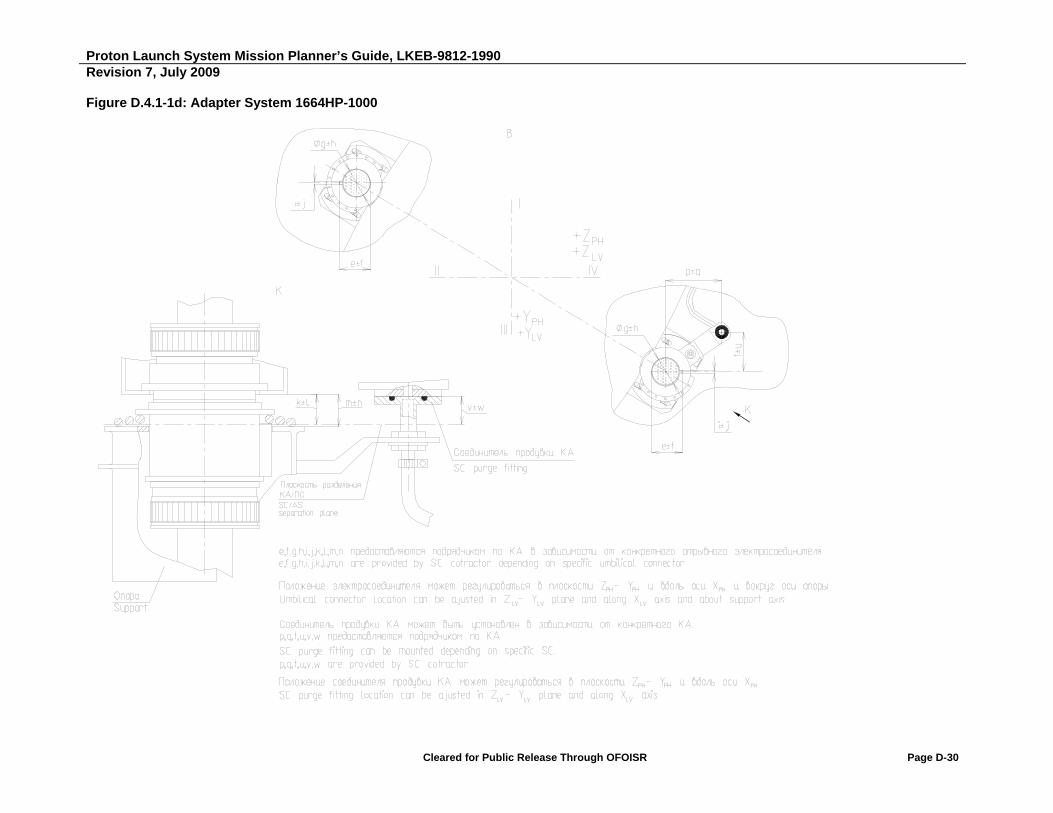
Proton Launch System Mission Planner’s Guide, LKEB-9812-1990 Revision 7, July 2009
Cleared for Public Release Through OFOISR Page D-30
Figure D.4.1-1d: Adapter System 1664HP-1000

Proton Launch System Mission Planner’s Guide, LKEB-9812-1990 Revision 7, July 2009
Cleared for Public Release Through OFOISR Page D-31
D.4.2 Load-Bearing Capability
The load-bearing capability of the AS structure is based on the allowable load determined after testing. The AS will hold down a SC having a maximum mass of 6000 kg, whose CG is located 1.7 m above the separation plane. This structural load-bearing capability is determined for standard interface ring geometrical parameters, specified in Fig. D.4.1-1c. Quasi-static accelerations used in the calculation are shown in Section 3.4.1.
The shown values of load-bearing capacity should be used only for preliminary evaluation of AS strength. During the early phase of SC integration with the LV, it will be necessary to perform a CLA to verify strength when loading the AS structure and the separation system.
D.4.3 Interface Ring Characteristics
The characteristics of the payload AS interface ring in the vicinity of the separation push springs are shown in Fig. D.4.1-1c.

Intentionally Blank

Proton Launch System Mission Planner’s Guide
APPENDIX E
Proton Launch System Options and Enhancements


Proton Launch System Mission Planner’s Guide, LKEB-9812-1990 Revision 7, July 2009
Cleared for Public Release Through OFOISR Page E-1
E. PAYLOAD ENVELOPE
This appendix presents information on payload envelopes under the PayLoad Fairings (PLFs).
The payload envelope is the volume available under the fairing for the Spacecraft (SC), with due regard for manufacturing clearances on outside dimensions and thermal insulation thickness, which are defined by the SC manufacturer, but without consideration of dynamic SC displacements and discrepancies in SC installation under the fairing, which are defined by KhSC.
A SC may extend beyond the payload envelope, if its dynamic displacements and installation discrepancies are taken into account.
The clearances between the SC and the fairing shall be not less than 50 mm, with due regard for manufacturing clearances and dynamic displacements.
Currently, the payload envelopes shown in Sections E.1 through E.4 may be used.
Table E.1: Fairings and Adapter Systems Defining Payload Envelopes
Fairing Adapter System Section
PLF-BR-13305 (length = 13,305 mm)
PLF-BR-15255 (length = 15,255 mm)
937VB-1168 E.1
1194VX-1000 (1194VS-1000) E.2
1666V-1000 E.3
1664HP-1000 E.4
Proton Launch System Mission Planner’s Guide, LKEB-9812-1990 Revision 7, July 2009
Cleared for Public Release Through OFOISR Page E-2
E.1 PAYLOAD ENVELOPE UNDER FAIRINGS PLF-BR-13305 AND PLF-BR-15255 WITH ADAPTER SYSTEM 937VB-1168
Figures E.1-1a and E.1-1b show the payload envelope dimensions that depend on the fairing type.
Figure E.1-1с shows the payload envelope dimensions that depend only on the 937VB-1168 Adapter System (AS) and that are identical for both fairings.
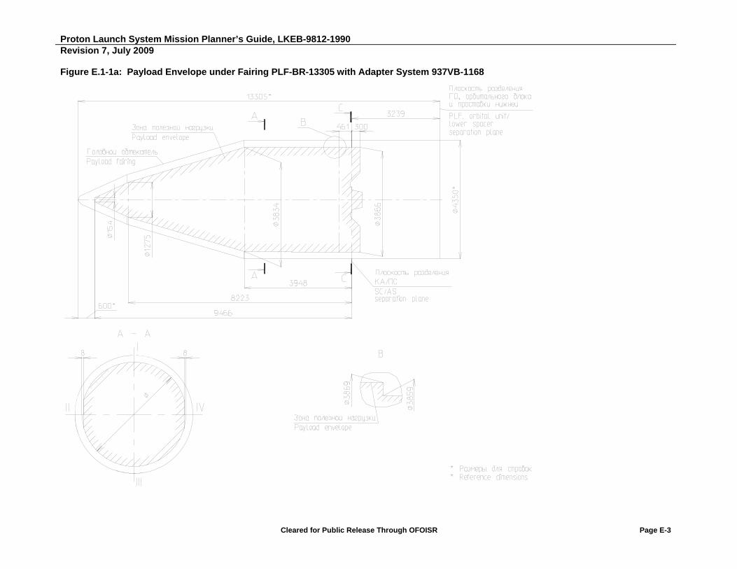
Proton Launch System Mission Planner’s Guide, LKEB-9812-1990 Revision 7, July 2009
Cleared for Public Release Through OFOISR Page E-3
Figure E.1-1a: Payload Envelope under Fairing PLF-BR-13305 with Adapter System 937VB-1168

Proton Launch System Mission Planner’s Guide, LKEB-9812-1990 Revision 7, July 2009
Cleared for Public Release Through OFOISR Page E-4
Figure E.1-1b: Payload Envelope under Fairing PLF-BR-15255 with Adapter System 937VB-1168

Proton Launch System Mission Planner’s Guide, LKEB-9812-1990 Revision 7, July 2009
Cleared for Public Release Through OFOISR Page E-5
Figure E.1-1c: Payload Envelope under Fairings PLF-BR-13305 and PLF-BR-15255 with Adapter System 937VB-1168
Proton Launch System Mission Planner’s Guide, LKEB-9812-1990 Revision 7, July 2009
Cleared for Public Release Through OFOISR Page E-6
E.2 PAYLOAD ENVELOPE UNDER FAIRINGS PLF-BR-13305 AND PLF-BR-15255 WITH ADAPTER SYSTEMS 1194VX-1000 AND 1194VS-1000
Figures E.2-1a and E.2-1b show the payload envelope dimensions that depend on the fairing type.
Figure E.2-1с shows the payload envelope dimensions that depend only on the 1194VX-1000 adapter system and that are identical for both fairings.
Figure E.2-1d shows the payload envelope dimensions that depend only on the 1194VS-1000 adapter system and that are identical for both fairings.

Proton Launch System Mission Planner’s Guide, LKEB-9812-1990 Revision 7, July 2009
Cleared for Public Release Through OFOISR Page E-7
Figure E.2-1a: Payload Envelope under Fairing PLF-BR-13305 with Adapter System 1194VX-1000 (1194VS-1000)
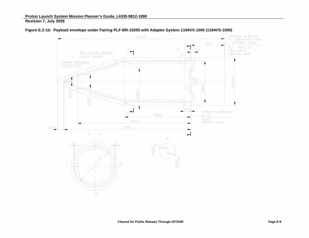
Proton Launch System Mission Planner’s Guide, LKEB-9812-1990 Revision 7, July 2009
Cleared for Public Release Through OFOISR Page E-8
Figure E.2-1b: Payload envelope under Fairing PLF-BR-15255 with Adapter System 1194VX-1000 (1194VS-1000)

Proton Launch System Mission Planner’s Guide, LKEB-9812-1990 Revision 7, July 2009
Cleared for Public Release Through OFOISR Page E-9
Figure E.2-1c: Payload Envelope under Fairings PLF-BR-13305 and PLF-BR-15255 with Adapter System 1194VX-1000

Proton Launch System Mission Planner’s Guide, LKEB-9812-1990 Revision 7, July 2009
Cleared for Public Release Through OFOISR Page E-10
Figure E.2-1d: Payload Envelope under Fairings PLF-BR-13305 and PLF-BR-15255 with Adapter System 1194VS-1000

Proton Launch System Mission Planner’s Guide, LKEB-9812-1990 Revision 7, July 2009
Cleared for Public Release Through OFOISR Page E-11
E.3 PAYLOAD ENVELOPE UNDER THE FAIRINGS PLF-BR-13305 AND PLF-BR-15255 WITH ADAPTER SYSTEM 1666V-1000
Figures E.3-1a and E.3-1b show the payload envelope dimensions that depend on the fairing type.
Figure E.3-1с shows the payload envelope dimensions that depend only on the 1666V-1000 adapter system and that are identical for both fairings.

Proton Launch System Mission Planner’s Guide, LKEB-9812-1990 Revision 7, July 2009
Cleared for Public Release Through OFOISR Page E-12
Figure E.3-1a: Payload Envelope under Fairing PLF-BR-13305 with Adapter System 1666V-1000

Proton Launch System Mission Planner’s Guide, LKEB-9812-1990 Revision 7, July 2009
Cleared for Public Release Through OFOISR Page E-13
Figure E.3-1b: Payload Envelope under Fairing PLF-BR-15255 with Adapter System 1666V-1000

Proton Launch System Mission Planner’s Guide, LKEB-9812-1990 Revision 7, July 2009
Cleared for Public Release Through OFOISR Page E-14
Figure E.3-1c: Payload Envelope under Fairings PLF-BR-13305 and PLF-BR-15255 with Adapter System 1666V-1000

Proton Launch System Mission Planner’s Guide, LKEB-9812-1990 Revision 7, July 2009
Cleared for Public Release Through OFOISR Page E-15
E.4 PAYLOAD ENVELOPE UNDER FAIRINGS PLF-BR-13305 AND PLF-BR-15255 ADAPTER SYSTEM 1664HP-1000
Figures E.4-1a and E.4-1b show the payload envelope dimensions that depend on the fairing type.
Figure E.4-1с shows the payload envelope dimensions that depend only on the 1664HP-1000 adapter system and that are identical for both fairings.

Proton Launch System Mission Planner’s Guide, LKEB-9812-1990Revision 7, July 2009
Cleared for Public Release Through OFOISR Page E-16
Figure E.4-1a: Payload Envelope under Fairing PLF-BR-13305 with Adapter System 1664HP-1000

Proton Launch System Mission Planner’s Guide, LKEB-9812-1990Revision 7, July 2009
Cleared for Public Release Through OFOISR Page E-17
Figure E.4-1b: Payload Envelope under Fairing PLF-BR-15255 with Adapter System 1664HP-1000

Proton Launch System Mission Planner’s Guide, LKEB-9812-1990Revision 7, July 2009
Cleared for Public Release Through OFOISR Page E-18
Figure E.4-1c: Payload Envelope under Fairings PLF-BR-13305 and PLF-BR-15255 with Adapter System 1664HP-1000

Proton Launch System Mission Planner’s Guide
APPENDIX F
Proton Launch System Options and Enhancements


Proton Launch System Mission Planner’s Guide, LKEB-9812-1990 Revision 7, July 2009
Cleared for Public Release Through OFOISR Page F-1
F. PROTON LAUNCH SYSTEM OPTIONS AND ENHANCEMENTS
The missions presented in the previous sections represent standard Geosynchronous Transfer Orbit (GTO)/ Geostationary Orbit (GSO) missions for the Proton M Launch Vehicle (LV) with the Breeze M Upper Stage. ILS can take advantage of the unique capabilities of the Proton launch system to design non-standard mission profiles to meet unique mission and payload requirements.
The long coast life and multiple restart capabilities of the Breeze M can also assist in constellation phasing, thereby reducing SC propellant usage.
ILS/KhSC also has the resources available to develop special hardware items, such as dispensers for multiple SC, to meet unique mission requirements.
F.1 LEO MISSIONS
Please contact ILS for specific Low Earth Orbit (LEO) mission performance.
F.2 MEO MISSIONS (INTERMEDIATE CIRCULAR ORBITS)
The Proton launch system performance and Breeze M restart capability allow Proton great flexibility in delivering payloads to circular Medium Earth Orbits (MEO). Table F.2-1 shows Proton M Breeze M Payload Systems Mass (PSM) performance and mission duration for injection into representative MEO target orbits.
Table F.2-1: Proton M Breeze M Performance to Intermediate Circular Orbits
Circular Orbit Altitude (km)
Proton M Breeze M PSM to Each Orbital Inclination (kg) Mission Duration
(hrs) 15 deg 28.6 deg 45 deg 51.5 deg 63.4 deg
10000 4115 5634 7650 7650 7272 5.3
15000 4049 5142 6491 6580 6225 6.1
20000 3852 4908 5756 5843 5575 6.9 Performances have been calculated for the standard PayLoad Fairing (PLF) (15,255 mm long). Free Molecular Heat Flux (FMHF) at the PLF jettison does not exceed 1135 W/m2. PSM includes LV AS mass. PSM has been defined for the Breeze M 2.33 propellant margin.
Note: Maximum PSM is 7650 kg based on structural capability of Breeze M.
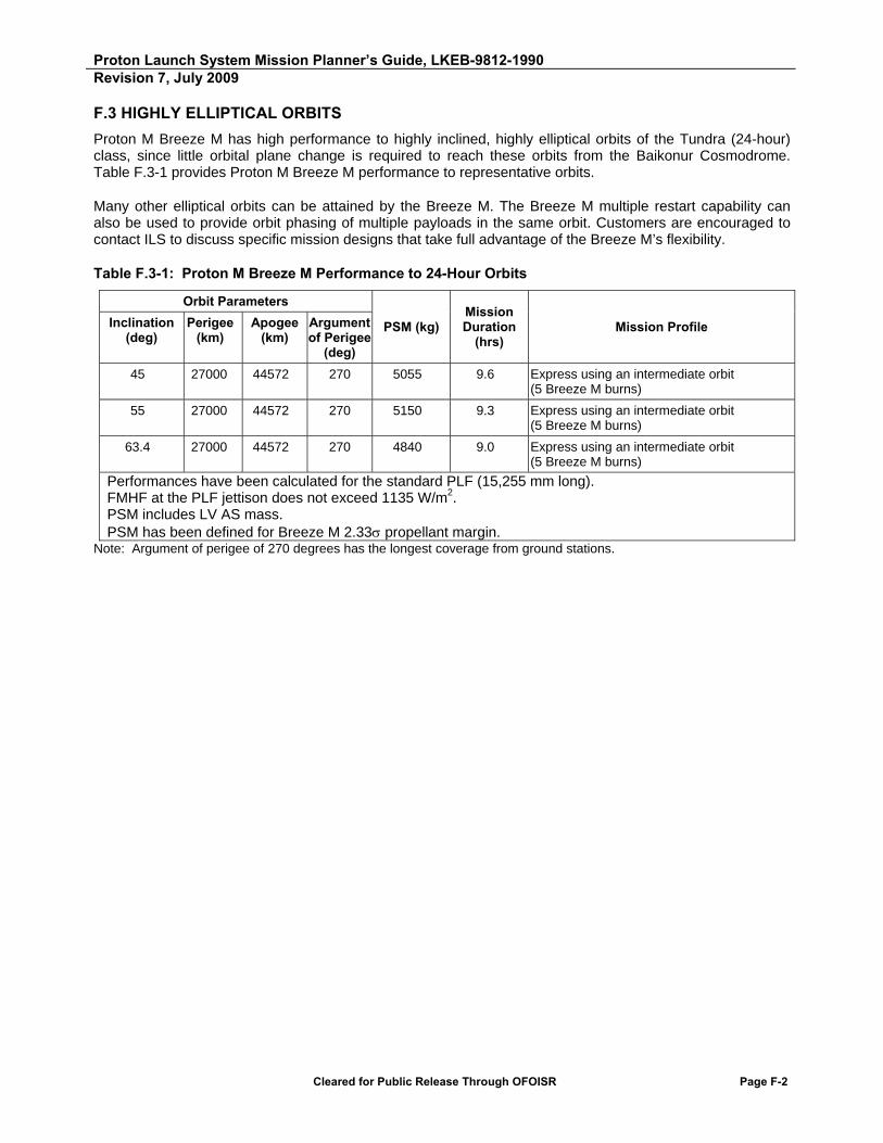
Proton Launch System Mission Planner’s Guide, LKEB-9812-1990 Revision 7, July 2009
Cleared for Public Release Through OFOISR Page F-2
F.3 HIGHLY ELLIPTICAL ORBITS
Proton M Breeze M has high performance to highly inclined, highly elliptical orbits of the Tundra (24-hour) class, since little orbital plane change is required to reach these orbits from the Baikonur Cosmodrome. Table F.3-1 provides Proton M Breeze M performance to representative orbits.
Many other elliptical orbits can be attained by the Breeze M. The Breeze M multiple restart capability can also be used to provide orbit phasing of multiple payloads in the same orbit. Customers are encouraged to contact ILS to discuss specific mission designs that take full advantage of the Breeze M’s flexibility.
Table F.3-1: Proton M Breeze M Performance to 24-Hour Orbits
Orbit Parameters
PSM (kg) Mission Duration
(hrs) Mission Profile Inclination
(deg) Perigee
(km) Apogee
(km) Argument of Perigee
(deg)
45 27000 44572 270 5055 9.6 Express using an intermediate orbit (5 Breeze M burns)
55 27000 44572 270 5150 9.3 Express using an intermediate orbit (5 Breeze M burns)
63.4 27000 44572 270 4840 9.0 Express using an intermediate orbit (5 Breeze M burns)
Performances have been calculated for the standard PLF (15,255 mm long). FMHF at the PLF jettison does not exceed 1135 W/m2. PSM includes LV AS mass. PSM has been defined for Breeze M 2.33 propellant margin.
Note: Argument of perigee of 270 degrees has the longest coverage from ground stations.
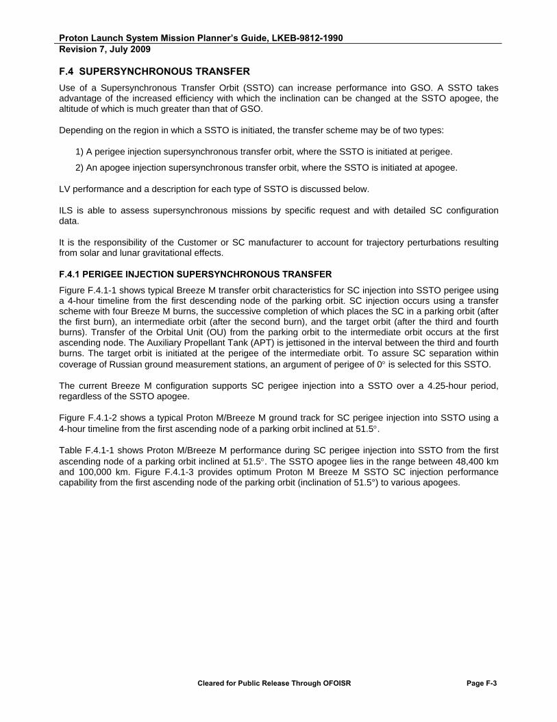
Proton Launch System Mission Planner’s Guide, LKEB-9812-1990 Revision 7, July 2009
Cleared for Public Release Through OFOISR Page F-3
F.4 SUPERSYNCHRONOUS TRANSFER
Use of a Supersynchronous Transfer Orbit (SSTO) can increase performance into GSO. A SSTO takes advantage of the increased efficiency with which the inclination can be changed at the SSTO apogee, the altitude of which is much greater than that of GSO.
Depending on the region in which a SSTO is initiated, the transfer scheme may be of two types:
1) A perigee injection supersynchronous transfer orbit, where the SSTO is initiated at perigee.
2) An apogee injection supersynchronous transfer orbit, where the SSTO is initiated at apogee.
LV performance and a description for each type of SSTO is discussed below.
ILS is able to assess supersynchronous missions by specific request and with detailed SC configuration data.
It is the responsibility of the Customer or SC manufacturer to account for trajectory perturbations resulting from solar and lunar gravitational effects.
F.4.1 PERIGEE INJECTION SUPERSYNCHRONOUS TRANSFER
Figure F.4.1-1 shows typical Breeze M transfer orbit characteristics for SC injection into SSTO perigee using a 4-hour timeline from the first descending node of the parking orbit. SC injection occurs using a transfer scheme with four Breeze M burns, the successive completion of which places the SC in a parking orbit (after the first burn), an intermediate orbit (after the second burn), and the target orbit (after the third and fourth burns). Transfer of the Orbital Unit (OU) from the parking orbit to the intermediate orbit occurs at the first ascending node. The Auxiliary Propellant Tank (APT) is jettisoned in the interval between the third and fourth burns. The target orbit is initiated at the perigee of the intermediate orbit. To assure SC separation within coverage of Russian ground measurement stations, an argument of perigee of 0 is selected for this SSTO.
The current Breeze M configuration supports SC perigee injection into a SSTO over a 4.25-hour period, regardless of the SSTO apogee.
Figure F.4.1-2 shows a typical Proton M/Breeze M ground track for SC perigee injection into SSTO using a 4-hour timeline from the first ascending node of a parking orbit inclined at 51.5.
Table F.4.1-1 shows Proton M/Breeze M performance during SC perigee injection into SSTO from the first ascending node of a parking orbit inclined at 51.5. The SSTO apogee lies in the range between 48,400 km and 100,000 km. Figure F.4.1-3 provides optimum Proton M Breeze M SSTO SC injection performance capability from the first ascending node of the parking orbit (inclination of 51.5°) to various apogees.
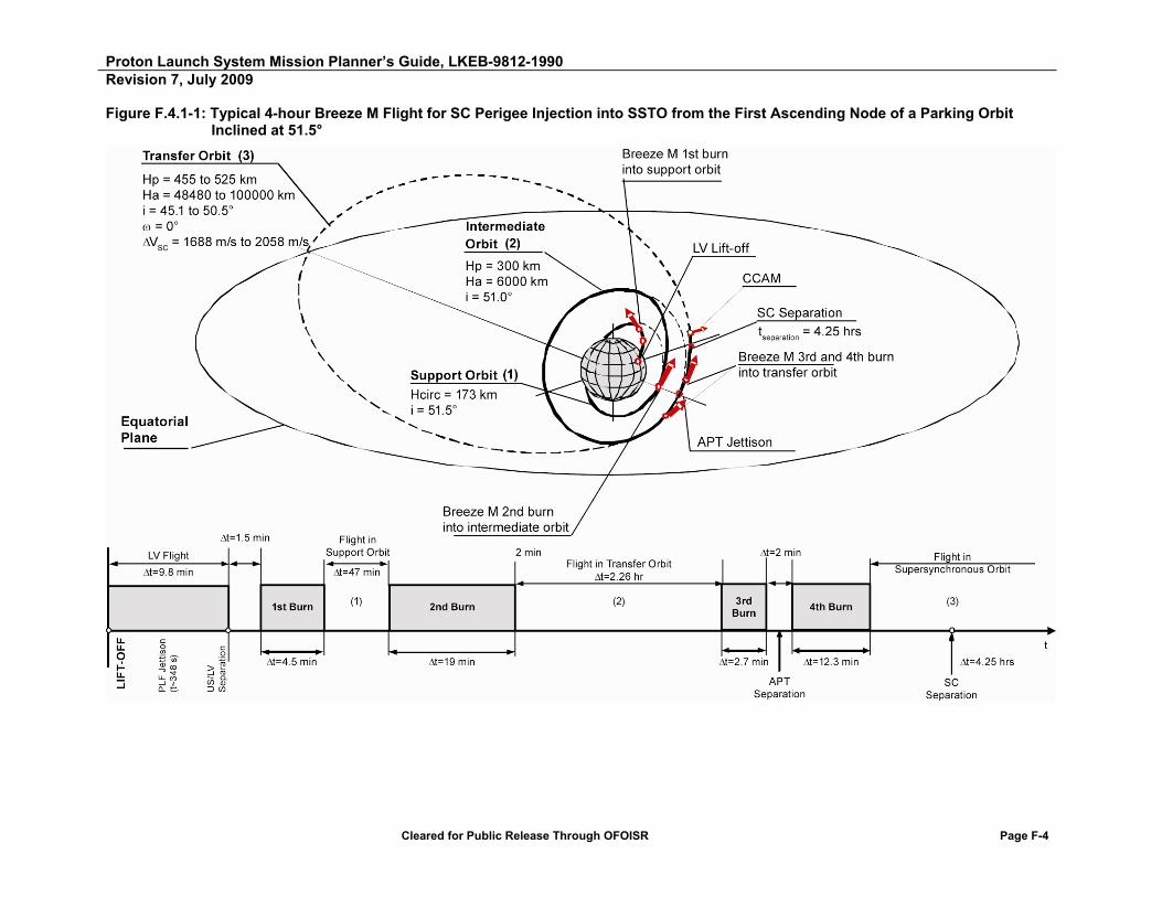
Proton Launch System Mission Planner’s Guide, LKEB-9812-1990 Revision 7, July 2009
Cleared for Public Release Through OFOISR Page F-4
Figure F.4.1-1: Typical 4-hour Breeze M Flight for SC Perigee Injection into SSTO from the First Ascending Node of a Parking Orbit Inclined at 51.5°

Proton Launch System Mission Planner’s Guide, LKEB-9812-1990 Revision 7, July 2009
Cleared for Public Release Through OFOISR Page F-5
Figure F.4.1-2: Typical Proton M/Breeze M Ground Track for SC Perigee Injection into SSTO (Ha = 100,000 km) Using a 4-hour Timeline from the First Ascending Node of a Parking Orbit Inclined at 51.5
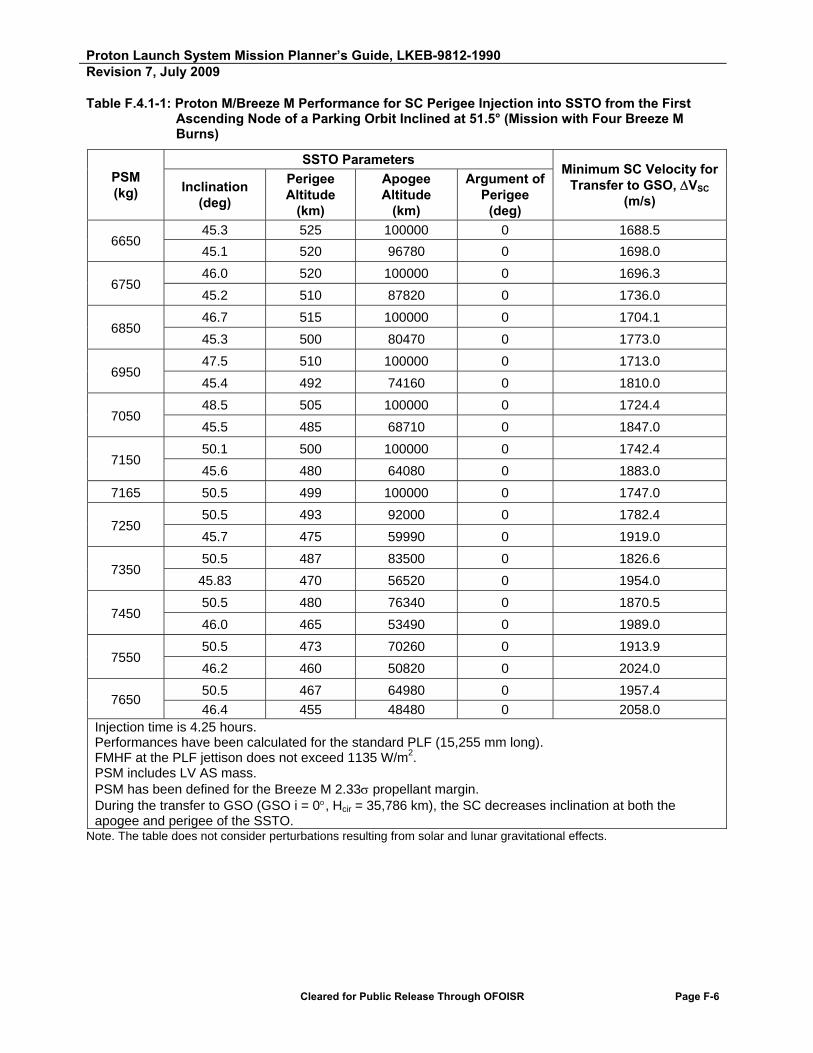
Proton Launch System Mission Planner’s Guide, LKEB-9812-1990 Revision 7, July 2009
Cleared for Public Release Through OFOISR Page F-6
Table F.4.1-1: Proton M/Breeze M Performance for SC Perigee Injection into SSTO from the First Ascending Node of a Parking Orbit Inclined at 51.5° (Mission with Four Breeze M Burns)
PSM (kg)
SSTO Parameters Minimum SC Velocity for
Transfer to GSO, VSC (m/s)
Inclination (deg)
Perigee Altitude
(km)
Apogee Altitude
(km)
Argument of Perigee
(deg)
6650 45.3 525 100000 0 1688.5
45.1 520 96780 0 1698.0
6750 46.0 520 100000 0 1696.3
45.2 510 87820 0 1736.0
6850 46.7 515 100000 0 1704.1
45.3 500 80470 0 1773.0
6950 47.5 510 100000 0 1713.0
45.4 492 74160 0 1810.0
7050 48.5 505 100000 0 1724.4
45.5 485 68710 0 1847.0
7150 50.1 500 100000 0 1742.4
45.6 480 64080 0 1883.0
7165 50.5 499 100000 0 1747.0
7250 50.5 493 92000 0 1782.4
45.7 475 59990 0 1919.0
7350 50.5 487 83500 0 1826.6
45.83 470 56520 0 1954.0
7450 50.5 480 76340 0 1870.5
46.0 465 53490 0 1989.0
7550 50.5 473 70260 0 1913.9
46.2 460 50820 0 2024.0
7650 50.5 467 64980 0 1957.4
46.4 455 48480 0 2058.0 Injection time is 4.25 hours. Performances have been calculated for the standard PLF (15,255 mm long). FMHF at the PLF jettison does not exceed 1135 W/m2. PSM includes LV AS mass. PSM has been defined for the Breeze M 2.33 propellant margin. During the transfer to GSO (GSO i = 0, Hcir = 35,786 km), the SC decreases inclination at both the apogee and perigee of the SSTO.
Note. The table does not consider perturbations resulting from solar and lunar gravitational effects.

Proton Launch System Mission Planner’s Guide, LKEB-9812-1990 Revision 7, July 2009
Cleared for Public Release Through OFOISR Page F-7
Figure 4.1-3: Payload System Mass Injected Into an Optimum SSTO from the First Ascending Node of a Parking Orbit Inclined at 51.5° (Mission with Four Breeze M Burns)
1650
1700
1750
1800
1850
1900
1950
2000
6600 6700 6800 6900 7000 7100 7200 7300 7400 7500 7600 7700
V
to G
SO
(m
/s)
Payload Systems Mass (kg)

Proton Launch System Mission Planner’s Guide, LKEB-9812-1990 Revision 7, July 2009
Cleared for Public Release Through OFOISR Page F-8
F.4.2 APOGEE INJECTION SUPERSYNCHRONOUS TRANSFER
A number of LV hardware and SC operational constraints may affect the design of missions utilizing apogee injection supersynchronous transfer.
Figure F.4.2-1 shows typical Breeze M transfer orbit characteristics for SC injection into SSTO (Ha = 65,000 km) using a 15-hour apogee injection timeline from the second descending node of a parking orbit inclined at 51.5. SC injection occurs using a transfer scheme with five Breeze M burns, the successive completion of which places the SC in a parking orbit (after the first burn), an intermediate orbit (after the second burn), a transfer orbit (after the third and fourth burns), and the target orbit (after the fifth burn). Transfer of the OU from the parking orbit to the intermediate orbit occurs at the second descending node of the parking orbit. The APT is jettisoned in the interval between the third and fourth burns. SSTO is initiated at the transfer orbit apogee.
An argument of perigee of 180 is selected to assure SC separation within coverage of Russian ground measurement stations.
Figure F.4.2-2 shows a typical Proton M/Breeze M ground track for SC apogee injection into SSTO (Ha = 65,000 km) using a 15-hour timeline from the second descending node of the parking orbit.
Table F.4.2-1 shows SC injection times and SC separation longitudes as a function of SSTO apogee.
Table F.4.2-2 provides SSTO SC injection performance capability at apogee for the Proton M Breeze M LV. The apogee varies from 50,000 km to 65,000 km. Figure F.4.2-3 provides optimum Proton M Breeze M SSTO SC injection performance capability from the second descending node of the parking orbit (inclination of 51.5) to an apogee of Ha = 65,000 km.
The current Breeze M configuration is capable of providing supersynchronous transfer missions up to 43,000 km apogee altitude. After implementation of additional modifications to the Breeze M and to the ground-based telemetry system, injection to SSTO with apogee altitudes of up to 65,000 km will become possible. The following are among the planned modifications:
- Installation of a new power supply aboard the Breeze M
- An update of onboard trajectory algorithms in the Breeze M control system
- An update of onboard Breeze M control system algorithms that are implemented during continuous rotation about the longitudinal axis
- Modification of the Breeze M control system to control new modes of telemetry data collection and transmission
- Modification of the Breeze M telemetry monitoring system to be able to use new modes of telemetry data collection and transmission
- An update of Breeze M onboard transmitters to enable use of new data transmission mode
- Equipping the ground-based telemetry system with hardware to receive telemetry and trajectory data at long ranges

Proton Launch System Mission Planner’s Guide, LKEB-9812-1990 Revision 7, July 2009
Cleared for Public Release Through OFOISR Page F-9
Figure F.4.2-1: Typical 15-hour Breeze M Mission for SC Apogee Injection into SSTO (Ha = 65,000 km) from the Second Descending Node of a Parking Orbit Inclined at 51.5
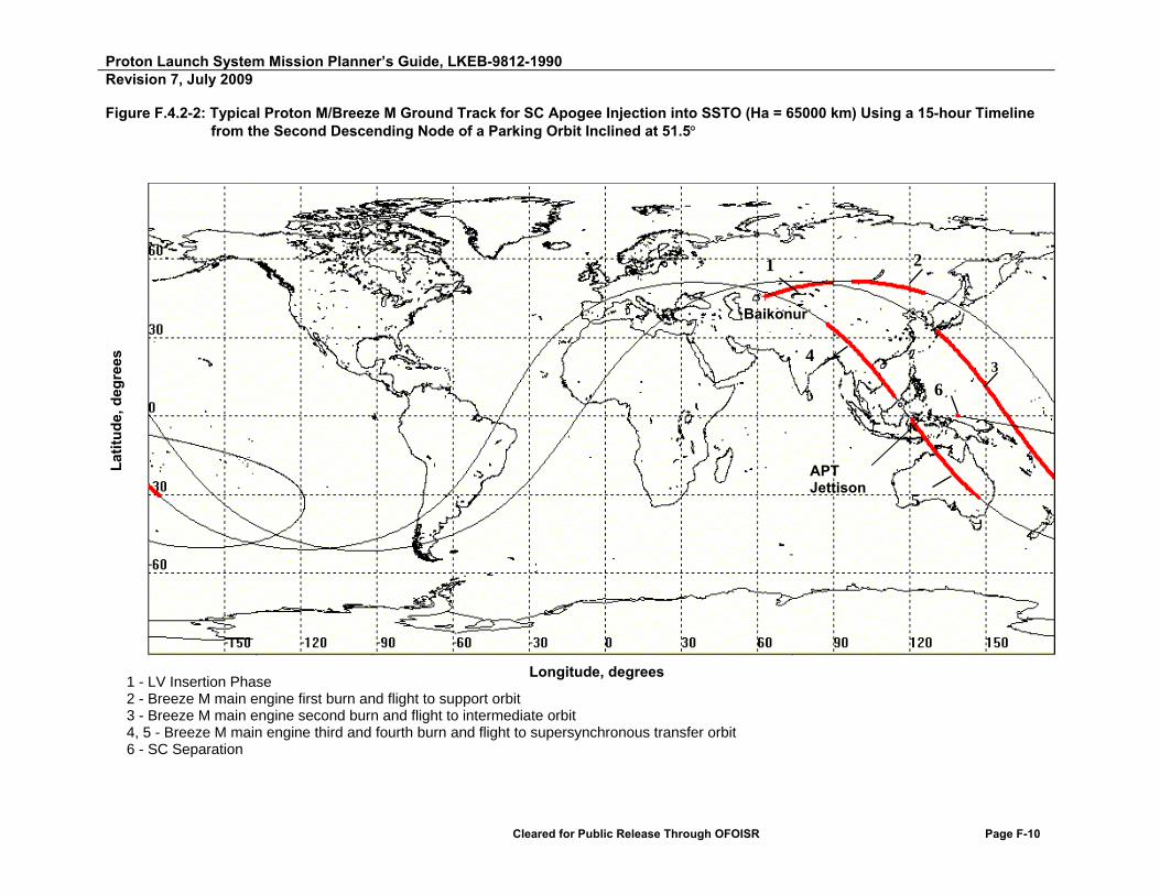
Proton Launch System Mission Planner’s Guide, LKEB-9812-1990 Revision 7, July 2009
Cleared for Public Release Through OFOISR Page F-10
Figure F.4.2-2: Typical Proton M/Breeze M Ground Track for SC Apogee Injection into SSTO (Ha = 65000 km) Using a 15-hour Timeline from the Second Descending Node of a Parking Orbit Inclined at 51.5
1 - LV Insertion Phase 2 - Breeze M main engine first burn and flight to support orbit 3 - Breeze M main engine second burn and flight to intermediate orbit 4, 5 - Breeze M main engine third and fourth burn and flight to supersynchronous transfer orbit 6 - SC Separation
Longitude, degrees
Lat
itu
de,
deg
rees
5
Baikonur
APT Jettison
4 3
1 2
6
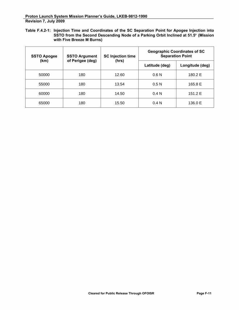
Proton Launch System Mission Planner’s Guide, LKEB-9812-1990 Revision 7, July 2009
Cleared for Public Release Through OFOISR Page F-11
Table F.4.2-1: Injection Time and Coordinates of the SC Separation Point for Apogee Injection into SSTO from the Second Descending Node of a Parking Orbit Inclined at 51.5 (Mission with Five Breeze M Burns)
SSTO Apogee (km)
SSTO Argument of Perigee (deg)
SC Injection time (hrs)
Geographic Coordinates of SC Separation Point
Latitude (deg) Longitude (deg)
50000 180 12.60 0.6 N 180.2 E
55000 180 13.54 0.5 N 165.8 E
60000 180 14.50 0.4 N 151.2 E
65000 180 15.50 0.4 N 136.0 E

Proton Launch System Mission Planner’s Guide, LKEB-9812-1990 Revision 7, July 2009
Cleared for Public Release Through OFOISR Page F-12
Table F.4.2-2: Proton M Breeze M Performance for SC Injection into Optimum SSTO from the Second Descending Node of the Parking Orbit with an Inclination of 51.5 (Profile with Five Breeze M Burns)
PSM (kg)
SSTO Parameters Minimum SC
velocity for transfer to GSO, Vsc (m/s)
Inclination (deg)
Perigee Altitude
(km)
Apogee Altitude
(km)
Argument of Perigee
(deg)
5250
13.8 11,497 65,000 180 1039 14.3 10,961 60,000 180 1049 14.8 10,355 55,000 180 1063 15.2 9650 50,000 180 1081
5350
15.0 10,540 65,000 180 1084 15.4 10,014 60,000 180 1095 15.8 9490 55,000 180 1108 16.2 8897 50,000 180 1126
5450
16.2 9609 65,000 180 1129 16.5 9162 60,000 180 1139 16.9 8742 55,000 180 1152 17.3 8255 50,000 180 1170
5550
17.4 8772 65,000 180 1172 17.6 8330 60,000 180 1183 18.0 8009 55,000 180 1196 18.35 7593 50,000 180 1214
5650
18.6 7954 65,000 180 1215 18.8 7608 60,000 180 1226 19.1 7322 55,000 180 1239 19.4 6971 50,000 180 1257
5750
19.9 7210 65,000 180 1258 20.0 6932 60,000 180 1268 20.3 6706 55,000 180 1282 20.5 6390 50,000 180 1300
5850
21.2 6511 65,000 180 1300 21.3 6322 60,000 180 1310 21.5 6128 55,000 180 1324 21.7 5900 50,000 180 1342
5950
22.5 5855 65,000 180 1341 22.6 5720 60,000 180 1352 22.7 5587 55,000 180 1365 22.85 5393 50,000 180 1384
6050
23.9 5262 65,000 180 1382 24.0 5212 60,000 180 1393 24.0 5108 55,000 180 1406 24.0 4942 50,000 180 1424
6150
25.4 4760 65,000 180 1422 25.4 4739 60,000 180 1433 25.3 4662 55,000 180 1446 25.2 4543 50,000 180 1463
6250
26.9 4290 65,000 180 1461 26.8 4275 60,000 180 1473 26.6 4225 55,000 180 1486
26.4 4150 50,000 180 1503

Proton Launch System Mission Planner’s Guide, LKEB-9812-1990 Revision 7, July 2009
Cleared for Public Release Through OFOISR Page F-13
PSM (kg)
SSTO Parameters Minimum SC
velocity for transfer to GSO, Vsc (m/s)
Inclination (deg)
Perigee Altitude
(km)
Apogee Altitude
(km)
Argument of Perigee
(deg)
6350
28.4 3827 65,000 180 1500 28.2 3835 60,000 180 1512 27.9 3812 55,000 180 1525 27.7 3772 50,000 180 1543
6450
30.0 3408 65,000 180 1539 29.7 3432 60,000 180 1551 29.3 3438 55,000 180 1564 29.0 3410 50,000 180 1583
6550
31.6 2993 65,000 180 1578 31.2 3040 60,000 180 1590 30.75 3060 55,000 180 1604 30.3 3068 50,000 180 1622
6650
33.3 2625 65,000 180 1617 32.7 2687 60,000 180 1628 32.2 2730 55,000 180 1642 31.65 2763 50,000 180 1661
6750
35.0 2290 65,000 180 1655 34.3 2360 60,000 180 1666 33.65 2430 55,000 180 1680 33.0 2485 50,000 180 1699
6850
36.8 1993 65,000 180 1693 35.9 2060 60,000 180 1704 35.1 2140 55,000 180 1718 34.4 2230 50,000 180 1737
6950
38.5 1700 65,000 180 1730 37.6 1787 60,000 180 1742 36.6 1890 55,000 180 1755 35.8 1995 50,000 180 1774
7050
40.3 1440 65,000 180 1766 39.2 1540 60,000 180 1778 38.1 1655 55,000 180 1791 37.2 1785 50,000 180 1810
7150
42.1 1200 65,000 180 1802 40,9 1320 60,000 180 1814 39,7 1452 55,000 180 1827 38,6 1585 50,000 180 1845
Performances have been calculated for the standard PLF (15,255 mm long). FMHF at the PLF jettison does not exceed 1135 W/m2. PSM includes LV AS mass. PSM has been defined for the Breeze M 2.33 propellant margin. During the transfer to GSO (GSO i = 0, Hcir = 35,786 km), the SC decreases inclination at both the apogee and perigee of the SSTO.
Note. The table does not consider perturbations resulting from solar and lunar gravitational effects.

Proton Launch System Mission Planner’s Guide, LKEB-9812-1990 Revision 7, July 2009
Cleared for Public Release Through OFOISR Page F-14
Figure F.4.2-3: Mass of Payload System Injected Into an Optimum SSTO (Ha = 65,000 km) Using a 15-hour Apogee Injection Scheme from the Second Descending Node of the Parking Orbit with an Inclination of 51.5° (Mission Profile with Five Breeze M Main Engine Burns)
1000
1100
1200
1300
1400
1500
1600
1700
1800
1900
5000 5500 6000 6500 7000 7500
V
to G
SO
(m
/s)
Payload Systems Mass (kg)

Proton Launch System Mission Planner’s Guide, LKEB-9812-1990 Revision 7, July 2009
Cleared for Public Release Through OFOISR Page F-15
F.5 EXPRESS GTO MISSION PROFILE
For Customers desiring to reduce the mission duration below seven hours, the Proton M Breeze M is capable of reaching GTO with an “Express” mission profile.
Figure F.5-1 illustrates typical Breeze M transfer orbit characteristics for SC injection into GTO using an Express mission. The Proton M delivers the OU into a sub-orbital trajectory. Subsequent SC injection occurs using a transfer scheme with four Breeze M burns, the successive completion of which places the SC in a parking orbit (after the first burn), a transfer orbit (after the second and third burns), and the target orbit (after the fourth burn). Transfer of the OU from the parking orbit to the transfer orbit occurs at the first ascending node. The APT is jettisoned in the interval between the second and third burns. An argument of perigee of 0 is selected to assure SC separation within coverage of Russian ground measurement stations.
Table F.5-1 shows Proton M/Breeze M performance for SC express injection into GTO using a 4-hr mission timeline from the first ascending node of a parking orbit inclined at 51.5.
Table F.5-1: Proton M/Breeze M Performance for SC Express Injection into GTO Using a 4-hour Mission Timeline from the First Ascending Node of a Parking Orbit Inclined at 51.5 (Mission with Four Breeze M Burns)
PSM (kg)
GTO Parameters SC velocity for
transfer to GSO, Vsc (m/s)
Inclination (deg)
Perigee Altitude
(km)
Apogee Altitude (km)
Argument of Perigee (deg)
4070 12.6 3405 35,786 0 1300
4270 14.4 2404 35,786 0 1400
4470 16.2 1466 35,786 0 1500
Injection time – 4 hours. Performances have been calculated for the standard PLF (15,255 mm long). FMHF at the PLF jettison does not exceed 1135 W/m2. PSM includes LV AS mass. PSM has been defined for the Breeze M 2.33 propellant margin.

Proton Launch System Mission Planner’s Guide, LKEB-9812-1990 Revision 7, July 2009
Cleared for Public Release Through OFOISR Page F-16
Figure F.5-1: Breeze M Typical Injection for 4-hour Express Mission into GTO from the First Ascending Node of a Parking Orbit Inclined at 51.5
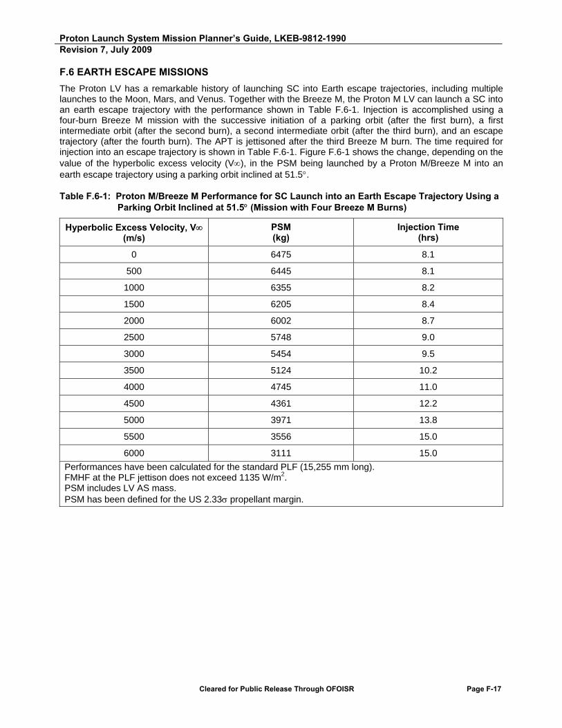
Proton Launch System Mission Planner’s Guide, LKEB-9812-1990 Revision 7, July 2009
Cleared for Public Release Through OFOISR Page F-17
F.6 EARTH ESCAPE MISSIONS
The Proton LV has a remarkable history of launching SC into Earth escape trajectories, including multiple launches to the Moon, Mars, and Venus. Together with the Breeze M, the Proton M LV can launch a SC into an earth escape trajectory with the performance shown in Table F.6-1. Injection is accomplished using a four-burn Breeze M mission with the successive initiation of a parking orbit (after the first burn), a first intermediate orbit (after the second burn), a second intermediate orbit (after the third burn), and an escape trajectory (after the fourth burn). The APT is jettisoned after the third Breeze M burn. The time required for injection into an escape trajectory is shown in Table F.6-1. Figure F.6-1 shows the change, depending on the value of the hyperbolic excess velocity (V), in the PSM being launched by a Proton M/Breeze M into an earth escape trajectory using a parking orbit inclined at 51.5.
Table F.6-1: Proton M/Breeze M Performance for SC Launch into an Earth Escape Trajectory Using a Parking Orbit Inclined at 51.5 (Mission with Four Breeze M Burns)
Hyperbolic Excess Velocity, V (m/s)
PSM (kg)
Injection Time (hrs)
0 6475 8.1
500 6445 8.1
1000 6355 8.2
1500 6205 8.4
2000 6002 8.7
2500 5748 9.0
3000 5454 9.5
3500 5124 10.2
4000 4745 11.0
4500 4361 12.2
5000 3971 13.8
5500 3556 15.0
6000 3111 15.0
Performances have been calculated for the standard PLF (15,255 mm long). FMHF at the PLF jettison does not exceed 1135 W/m2. PSM includes LV AS mass. PSM has been defined for the US 2.33 propellant margin.

Proton Launch System Mission Planner’s Guide, LKEB-9812-1990Revision 7, July 2009
Cleared for Public Release Through OFOISR Page F-18
Figure F.6-1: Payload System Mass Injected by Proton M/Breeze M into an Earth Escape Trajectory Using a Parking Orbit Inclined at 51,5 (Mission with Four Breeze M Burns)
2500
3000
3500
4000
4500
5000
5500
6000
6500
7000
0 1000 2000 3000 4000 5000 6000 7000
Hyp
erb
olic
Ex
ce
ss
Ve
loc
ity,
V∞
(m/s
)
Payload Systems Mass (kg)

Proton Launch System Mission Planner’s Guide, LKEB-9812-1990 Revision 7, July 2009
Cleared for Public Release Through OFOISR Page F-19
F.7 FIVE-METER DIAMETER PAYLOAD FAIRINGS
The Proton 5-meter diameter PLF, designated PLF-BR-17255, is currently under development by KhSC. This PLF has an external diameter of 5100 mm, an overall length of 17255 mm, and an internal useable volume with dimensions comparable to, or greater than, those of other 5-meter fairings available in the industry. The payload envelope under the PLF-BR-17255 fairing, using the 1666V–1000 adapter system, is shown in Figures F.7-1a and F.7-1b. As required by the Customer, other types of adapters may be used together with the PLF-BR-17255 fairing.
The Proton 5-meter PLF will be offered in conjunction with the Breeze M Upper Stage and mission design enhancements that will allow the Proton to retain a performance capability of 5850 kg to a geo-transfer orbit with a delta-V of 1500 m/s.
Other PLF options have also been assessed for development and use with the commercial Proton M Breeze M configuration. These options include PLFs with unique geometries needed to accommodate unusual SC configurations. ILS and KhSC are willing to develop these concepts with the award of firm launch services contracts. Such PLF options can take up to 48 months from contract signing to becoming available.

Proton Launch System Mission Planner’s Guide, LKEB-9812-1990 Revision 7, July 2009
Cleared for Public Release Through OFOISR Page F-20
Figure F.7-1a: Payload Envelope Under Proton Breeze M 5-Meter PLF Fairing (Sheet 1 of 2)

Proton Launch System Mission Planner’s Guide, LKEB-9812-1990 Revision 7, July 2009
Cleared for Public Release Through OFOISR Page F-21
Figure F.7-1b: Payload Envelope Under Proton Breeze M 5-Meter PLF Fairing (Sheet 2 of 2)

Proton Launch System Mission Planner’s Guide, LKEB-9812-1990 Revision 7, July 2009
Cleared for Public Release Through OFOISR Page F-22
F.8 TANDEM LAUNCH SYSTEM
In addition to large volume PLF options, KhSC has studied and conceptually designed a Tandem Launch System (TLS) payload carrier concept. The TLS concept may offer attractive opportunities for launch of multiple payload constellations to various orbits.
F.9 SHARED LAUNCH WITH THE YAKHTA SC BUS
The Russian Yakhta SC bus is designed as a load carrying structure for an adapter and second SC attached to its upper surface. The shared launch concept is offered for launches of single SC weighing less than 3200 kg. A schematic of the shared launch concept is shown in Figure F.9-1. The load carrying capability of the Yakhta SC bus in shared launch configuration is shown in Figure F.9-2. The first shared launch of Russian SC into GTO aboard a Proton M/Breeze M took place in February 2009.

Proton Launch System Mission Planner’s Guide, LKEB-9812-1990 Revision 7, July 2009
Cleared for Public Release Through OFOISR Page F-23
Figure F.9-1: Layout of the Shared Launch Concept with the Yakhta SC Bus

Proton Launch System Mission Planner’s Guide, LKEB-9812-1990 Revision 7, July 2009
Cleared for Public Release Through OFOISR Page F-24
Figure F.9-2: Allowable Variation in the CG of the Second SC as a Function of the Mass of the Second SC in a Shared SC Launch on the Yakhta SC Bus
0.0
0.2
0.4
0.6
0.8
1.0
1.2
1.4
1.6
1.8
2.0
2.2
2.4
2.6
2.8
3.0
3.2
1400 1600 1800 2000 2200 2400 2600 2800 3000 3200 3400 3600 3800 4000 4200
SC
CG
Rel
ativ
e to
SC
Sep
arat
ion
Pla
ne
(m)
Upper SC Mass (kg)
F.10 SUMMARY
As ILS and KhSC continue to explore the next evolutionary steps in Proton commercial launch services, we look forward to discussing with potential Customers their requirements for increased performance, fairing volume or mission design flexibility to meet near-term commercial launch services needs.

Intentionally Blank
Преднамеренно незаполнено
www.ilslaunch.com
Experience ILS | Achieve Your MissionQuALItY | PErforMAncE | ExPErIEncE | DEDIcAtIon
IntErnAtIonAL LAuncH SErVIcES 1875 ExplorEr DrivE, SuitE 700rESton, virginia 20190 uSa
tEl +1 571 633 7400Fax +1 571 633 7500
www.ilslaunch.com