proposition 65 warning -...
TRANSCRIPT

WARNING
The engine exhaust from thisproduct contains chemicals
known to cause cancer, birth de-fects or other reproductive harm.
PROPOSITION 65WARNING
Snowmobile engines discharge fueland exhaust, which contain chemicalsknown to the State of California to
cause cancer and birth defects or otherreproductive harm, onto the snow onwhich they operate. Keep this engineproperly tuned and avoid unnecessary
idling and spillage during fueling.

2000UniversalSnow
Part No. 9915247 Rev 02PRINTED IN THE U.S.A.
¯ Adult Vehicle Only: This vehicle is designed for adult use only. The vehiclesize, speed capabilities and control requirement prohibit operation by children.¯ Operating With A Passenger: (On approved models only) Operating a vehiclewith a passenger reduces your ability to control the vehicle due to the added weight andchange in weight distribution. Generally, reduce vehicle speeds andprovide addedspacefor maneuvering, since steering control may be reduced.¯ Excessive speeds: This vehicle is capable of high speeds. Exercise extremecaution when operating in unfamiliar terrain. Buried objects or uneven terrain can causeloss of control.¯ Body Protection: Always wear an approved helmet, eye protection andadequate clothing while operating this vehicle.¯ Alcohol Or Drugs: Never consume alcohol or drugs before or while operatingthis vehicle.¯ Night Riding and Limited Visibility: Limited visibility or excessive speeds maycause over-driving of headlights resulting in insufficient time to react to terrain changes oravoidance of unexpected obstacles.¯ Auxiliary Shut Off Switch: This switch is the primary means of stopping thisvehicle in case of an emergency and is located on the top of the throttle control assembly.Depress the switch for proper function with the engine idling.¯ Safety Throttle System: This system is a supplementary safety device whichstops the engine automatically in the event of a throttle system malfunction. See theOwner’s Manual for procedure to ensure proper system operation.¯ Vehicle Control: The Steering and braking ability are greatly reduced whenoperating on hardpacked snow, ice or when crossing roads. Reduced speed and extracare are required to maintain vehicle control.¯ Ski Skag Inspection: Inspect ski skags for wear every 500 miles or more oftenwhen operating on abrasive surface conditions. Replace ski skags when worn to 1/2 oforiginal diameter.¯ Carbide Skags and Studs: These items enhance vehicle control on ice orhardpacked surfaces. Care must be taken to maintain a proper balance of ski carbides totrack studs tomaintain proper vehicle control. (See the Owner’s Manual for proper use oftraction accessories.)¯ Cargo Rack: If this vehicle is equipped with a cargo rack, do not sit in or on thecargo rack. The combined cargo load and tongue weight on the hitch should not exceed75 lbs . (34 kgs.) Cargo load affects machine steering and braking response.¯ Rotating Track: Stay clear of the rotating track assembly. Entanglement mayresult.¯ Unfamiliar Rider: Never permit a guest to operate this vehicle unless the guesthas read the Owner’s Manual and warnings.¯ Adjustment andService: If youarenot familiarwith safeadjustment andserviceprocedures, bring your vehicle to a qualified dealer for servicing or adjustment.¯ Read and understand warnings and the Owner’s Manual before operation.Severe injury or death can result from not heeding the warnings or understanding theOwner’s Manual.OIL INJECTION SYSTEM. UNMIXED FUEL ONLY. CHECK OIL LEVEL WHENREFUELING.
WARNING
Owner’s Safety
and Maintenance Manual

FOREWORDThank you for purchasing a Polaris snowmobile. We believe it is the standard ofexcellence for all snowmobiles manufactured in the world today. Many years ofexperience in engineering, design, and development have gone into making yourPolaris snowmobile the finest machine we have ever produced.All machines, no matter how well engineered, require a certain amount of mainte-nance. Before using your snowmobile, take a few minutes to read through thismanual and familiarize yourself with maintenance and operation procedures. Itmay be the most important time spent in knowing how to keep your machine run-ning perfectly every day.If the registration form included with your snowmobile has not been com-pleted by you and your dealer, be certain that it is; and make sure that it isforwarded to us. This completed form is necessary to insure warranty cover-age.This manual also contains important pages devoted to safety and environment.Whether you are a long-time snowmobiler or a newcomer to this exciting wintersport, we urge you to seriously read this information.Remember, your snowmobile is capable of traveling at high speeds. This perfor-mance has been engineered into yourPolaris to allow you the ultimate snowmobil-ing experience. Operators must be aware of risks involved when traveling at highspeeds, on iced or hard packed surfaces, at night or in unfamiliar terrain. In addi-tion, young or novice riders who do not have the ability or experience to physicallycontrol themachine in difficult situations should be instructed to reduce their speeduntil they become skilled riders.On machines designated for two passengers it is most important that the operatorand rider communicate well and practice cornering techniques, rough terrain rid-ing, etc., so that each is contributing to a safe, enjoyable ride. Keep the runningboard non-skid pads free of ice and snowand in good condition for increased safe-ty and passenger comfort. The safe and courteous operation of your snowmobile- with respect for the environment - will insure you the continued enjoyment of thesport of snowmobiling.If you should experience any problems with your snowmobile, please return it toyour dealer. He has received trainingwhichwill enable him to perform any requiredrepairs. Should any additional assistance be required, your dealer will work withour technical services department to resolve any problems.All of us at Polaris would like to extend to you our bestwishes for plenty of fun-filled,safe snowmobiling pleasure with your new Polaris.All information in this manual is based upon the latest product data and specifica-tions available at the time of printing. Polaris Industries Inc. reserves the right tomake product changes and improvements which may affect illustrations or ex-planations.No part of this manual shall be reproduced or used without the written permissionof Polaris Industries Inc.Illustrations included in this manual are general representations of parts having asimilar function. Your model may differ.

The Polaris PreferredRegistered Owners
(PRO) FamilyYour Owners Program
As the owner of a new Polaris vehicle, you are entitled to a FREE two- year mem-bership in the Polaris PRO Family---the Preferred Registered Owners Family. It’san owners program for Polaris owners like you, peoplewho have chosen the finestrecreational vehicle available, people who share an interest in Polaris and its prod-ucts.
Once your new vehicle’s warranty is registered, you will receive a PRO Familymembership packet that will include:
A letter of welcome to the PRO Family
A PRO Family card with your name and membership number
A colorful sticker of the PRO logo
A PRO merchandise brochure and order form.
As a PRO Family member, you’re entitled to opportunities such as:
A free subscription to PRO Spirit, the official magazine of the PRO Family
The chance to buy insurance for you Polaris vehicle. The toll-free insurancetelephone number is: 1-800-473-0111
The chance to arrange travel through the Polaris Travel Center. The toll-freetravel telephone number is: 1-800-267-1915
The chance to apply to serve on PRO Consumer Councils that provide inputinto the Polaris vehicles of the future
The chance to serve as a PRO Field Evaluator and provide feedback on yournew vehicle
The chance to take part in national PRO snowmobile, ATV or personal water-craft rides
The chance to purchase exclusive PRO Family merchandise
And more!
To order PRO merchandise, you’ll complete the order form you receive with yourmembership packet, take the form to your Polaris dealer and pay for the merchan-dise. The merchandise will be shipped directly to your home from the PRO mer-chandise fulfillment center.Watch for your PRO membership packet and the next issue of PRO Spiritmaga-zine. This quarterly magazine will keep you informed about Polaris news andevents, and special PRO merchandise, travel, and ride opportunities.
Enjoy your new Polaris vehicle and welcome to the family--The Polaris PRO Family.

TABLE OF CONTENTS
UNDERSTANDING WARNINGS 1. . . . . . . . . . . . . . . . . . . . . . . . . . . . . . . .
SAFETY WARNING AND OPERATION DECALS 2-9. . . . . . . . . . . . . . .
OPERATION WARNINGS 10-24. . . . . . . . . . . . . . . . . . . . . . . . . . . . . . . . .
PRESERVATION OF THE ENVIRONMENT 25. . . . . . . . . . . . . . . . . . . . .
IDENTIFICATION AND SPECIFICATIONS 26-30. . . . . . . . . . . . . . . . . . .
OPERATION 31-44. . . . . . . . . . . . . . . . . . . . . . . . . . . . . . . . . . . . . . . . . . . . .
BATTERY 45-47. . . . . . . . . . . . . . . . . . . . . . . . . . . . . . . . . . . . . . . . . . . . . . . .
MAINTENANCE 48-105. . . . . . . . . . . . . . . . . . . . . . . . . . . . . . . . . . . . . . . . .
SUSPENSION 106-134. . . . . . . . . . . . . . . . . . . . . . . . . . . . . . . . . . . . . . . .
TROUBLESHOOTING 135-141. . . . . . . . . . . . . . . . . . . . . . . . . . . . . . . . .
ACCESSORIES 142. . . . . . . . . . . . . . . . . . . . . . . . . . . . . . . . . . . . . . . . . . .
SERVICE AND WARRANTY 143. . . . . . . . . . . . . . . . . . . . . . . . . . . . . . . .
WARRANTY 144-147. . . . . . . . . . . . . . . . . . . . . . . . . . . . . . . . . . . . . . . . . .
INDEX 148-149. . . . . . . . . . . . . . . . . . . . . . . . . . . . . . . . . . . . . . . . . . . . . . .

1
UNDERSTANDING WARNINGS
SAFETY ALERT
The following precautionary signal words are used throughout this manual to con-vey the following messages:
This is the safety alert symbol. When you see thissymbol on yourmachine or in this manual, be alertto the potential for personal injury. Your safety isinvolved!
WARNINGIndicates a potential haz-ard which could result inserious injury or death.
CAUTIONIndicates a potential hazardwhichmay result in minor per-sonal injury or damage to thesnowmobile.
NOTETheword “NOTE:” in thismanualwillalert you to key information orinstructions.

2
SAFETY WARNING AND OPERATION DECALS
WARNING
Driving a snowmobile requires yourfull attention. Do not drink alcohol oruse drugs or medications before orwhile driving as they will reduce youralertness and slow your reactiontime. In most states and provinces itis prohibited by law to drive while in-toxicated or under the influence ofdrugs.
Be smart, be safe, don’t drink anddrive!

3
SAFETY WARNING AND OPERATION DECALS
WARNINGPolaris Indys are high performance snowmobiles capable of traveling at very highspeeds. Because of this, extra caution must be observed to ensure operator safe-ty. Particular caution must be taken to make sure that the snowmobile is in excel-lent operating condition at all times. As with any performance snowmobile, westrongly recommend the operator check major and vital safety components eachtime before riding.
All Polaris snowmobiles have been designed and tested to provide safe operationwhen used as directed. Failure of critical machine components may result fromoperation with any modification; especially those which increase speed or power.The machines may become aerodynamically unstable at speeds above those forwhich they are designed. There is also a significant possibility of loss of control athigher speeds.
Due to our concern for the safety of our customers and the general public, Polarishereby strongly recommends and requests that consumers do not install on a Po-laris snowmobile any equipment which is intended to increase the speed or powerof the machine, or make any other modifications to the machines for these pur-poses. Any modifications to the original equipment or the snowmobiles substan-tially increase the risk of bodily injury. Be aware that these modifications maycreate a substantial safety hazard.
Polaris hereby informs you that the warranty on a snowmobile is terminated on theentiremachine if any such equipment has been added to themachine or anymodi-fications have been made to the machine which increase its speed or power.
We also advise you to strictly follow the recommendedmaintenance program out-lined on pages 48-100. This preventative maintenance program is designed to en-sure that all critical components on the snowmobile are thoroughly inspected byyour dealer at various mileage intervals.

4
SAFETY WARNING AND OPERATION DECALS
Your snowmobile is not a toy. It is a well-engineered and well constructed recre-ational vehicle. The following information is provided to aid you in its safe opera-tion.
NOTE: Warning decals have been placed on the vehicle for your protection. Readand follow the instructions on each decal carefully. In the eventany decalbecomesillegible or comes off, contact yourPolaris dealer for a replacement. Any safety de-cal needing replacementwill be provided byPolaris at no charge. The part numberis printed on the decal.
CAUTION: Although your Polaris has been designed to provide you with a safe,reliable snowmobile, much of its safety depends on the operator. Improper use ofthis snowmobile or failure to maintain it in good operating condition can result ininjury. To reduce this possibility, read the following important safety information.

5
SAFETY WARNING AND OPERATION DECALS
D Read and understand warnings and the Owner’s Manual beforeoperation. Severe injury or death can result from not heeding the warnings.D Never consume alcohol or drugs before or while operating this vehicle.D Night riding, limited visibility, or excessive speeds may causeover-driving of headlights resulting in insufficient time to react to terrainchanges or avoid unexpected obstacles.D This vehicle is capable of high speeds. Buried objects or uneven terraincan cause loss of control. Exercise extreme caution when operating inunfamiliar terrain.D This vehicle is designed for adult use only. The vehicle size, speedcapabilities and control requirement prohibit operation by children.D Operating this vehicle with a passenger (On approved models only)reduces your ability to control the vehicle due to the added weight andchange in weight distribution. Reduce vehicle speeds and allow addedspace for maneuvering, since steering control may be reduced.D Alwayswear an approved helmet, eye protection and adequate clothingwhile operating this vehicle.D The Auxiliary Shut Off Switch is the primary means of stopping thisvehicle in case of an emergency and is located on the top of the throttlecontrol assembly. Depress the switch to stop the engine and vehicle.Routinely check this switch for proper function with the engine idling.D The steering and braking ability are greatly reduced when operating onhard packed snow, ice or when crossing roads. Reduced speed and extracare are required to maintain vehicle control.D Carbide skags and studs enhance vehicle control on ice or hard-packedsurfaces. Care must be taken to maintain a proper balance of ski carbides totrack studs to maintain proper vehicle control. (See the Owner’s Manual forproper use of traction accessories.D Never permit a guest to operate this vehicle unless the guest has readthe Owner’s Manual and warnings.
WARNING
(Text Below)

6
SAFETY WARNING AND OPERATION DECALS
7075457
(Text Below)
BEFORE STARTING ENGINE: Check throttle and brake for proper operation.Check to see that hood is securely latched. Check surroundings to verify clear op-eration area. Determine that steering is free and functional.
BRAKELEVERLOCK: May relaxwhen used for long periods. Do not leavebrakeengaged for more than five minutes.
ALWAYS:Be seated and in position to control vehicle. Stop engine beforeattempt-ing adjustments. Know the limitations of the vehicle and your skills as a driver. Un-derstand your Owner’s Manual. Wear clothing designed for snowmobiling. Stopsfrom high speed may cause fading or unexpected loss of braking ability.
Oil injection system: Unmixed fuel only. Check oil level when refueling.
If you do not have theOwner’sManual for this vehicle, call 1-800-324-3764 to haveone provided at no charge.
7
SAFETY WARNING AND OPERATION DECALS
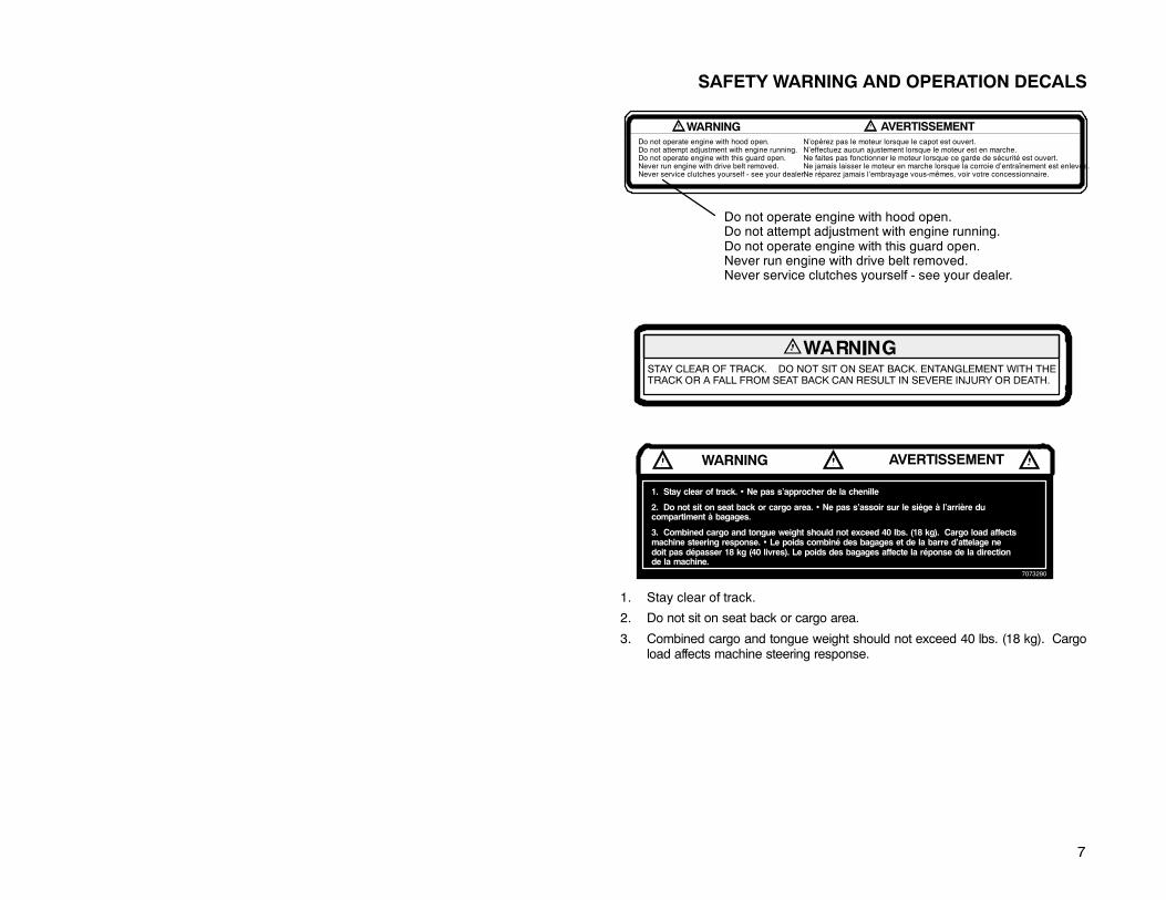
STAY CLEAR OF TRACK. DO NOT SIT ON SEAT BACK. ENTANGLEMENT WITH THETRACK OR A FALL FROM SEAT BACK CAN RESULT IN SEVERE INJURY OR DEATH.
WARNING AVERTISSEMENTDo not operate engine with hood open.Do not attempt adjustment with engine running.Do not operate engine with this guard open.Never run engine with drive belt removed.Never service clutches yourself - see your dealer.
N’opérez pas le moteur lorsque le capot est ouvert.N’effectuez aucun ajustement lorsque le moteur est en marche.Ne faites pas fonctionner le moteur lorsque ce garde de sécurité est ouvert.Ne jamais laisser le moteur en marche lorsque la corroie d’entraînement est enlevée.Ne réparez jamais l’embrayage vous-mêmes, voir votre concessionnaire.
Do not operate engine with hood open.Do not attempt adjustment with engine running.Do not operate engine with this guard open.Never run engine with drive belt removed.Never service clutches yourself - see your dealer.
WARNING AVERTISSEMENT
1. Stay clear of track. • Ne pas s’approcher de la chenille
2. Do not sit on seat back or cargo area. • Ne pas s’assoir sur le siège à l’arrière ducompartiment à bagages.
3. Combined cargo and tongue weight should not exceed 40 lbs. (18 kg). Cargo load affectsmachine steering response. • Le poids combiné des bagages et de la barre d’attelage nedoit pas dépasser 18 kg (40 livres). Le poids des bagages affecte la réponse de la directionde la machine.
7073290
1. Stay clear of track.
2. Do not sit on seat back or cargo area.
3. Combined cargo and tongue weight should not exceed 40 lbs. (18 kg). Cargoload affects machine steering response.

8
SAFETY WARNING AND OPERATION DECALS
VEHICLE CAPABLE OF EXCESSIVE REVERSE SPEED!Reverse operation can be dangerous even at low speeds. Steering controlbecomes difficult in reverse. Misuse of reverse can result in injury. Avoidturning at sharp angles in reverse.
Transmission may not always be in the gear indicated by the shift lever. Al-ways apply throttle slowly.
On machines with reverse it is especially important to maintain track tensionas specified in the owner’s manual. If specified track tension is not main-tained severe damage to the machine may occur, which can result in loss ofvehicle control. Loss of vehicle control can result in severe personal injury ordeath.
For More Info: See Operator’s Safety and Maintenance Manual suppliedwith reverse kit.
SHIFT PATTERN
Make sure lever is shifted completely to forward or reverse position. Do notforce into reverse. If not able to shift to reverse, apply throttle gently to movevehicle. CAUTION: Do not attempt to shift until machine has come to acomplete stop or chaincase damage may occur.
(Text Below)
Models Equipped With Reverse Only
NOTE: Illustration of shift pattern may vary. Your model may differ.
9
SAFETY WARNING AND OPERATION DECALS
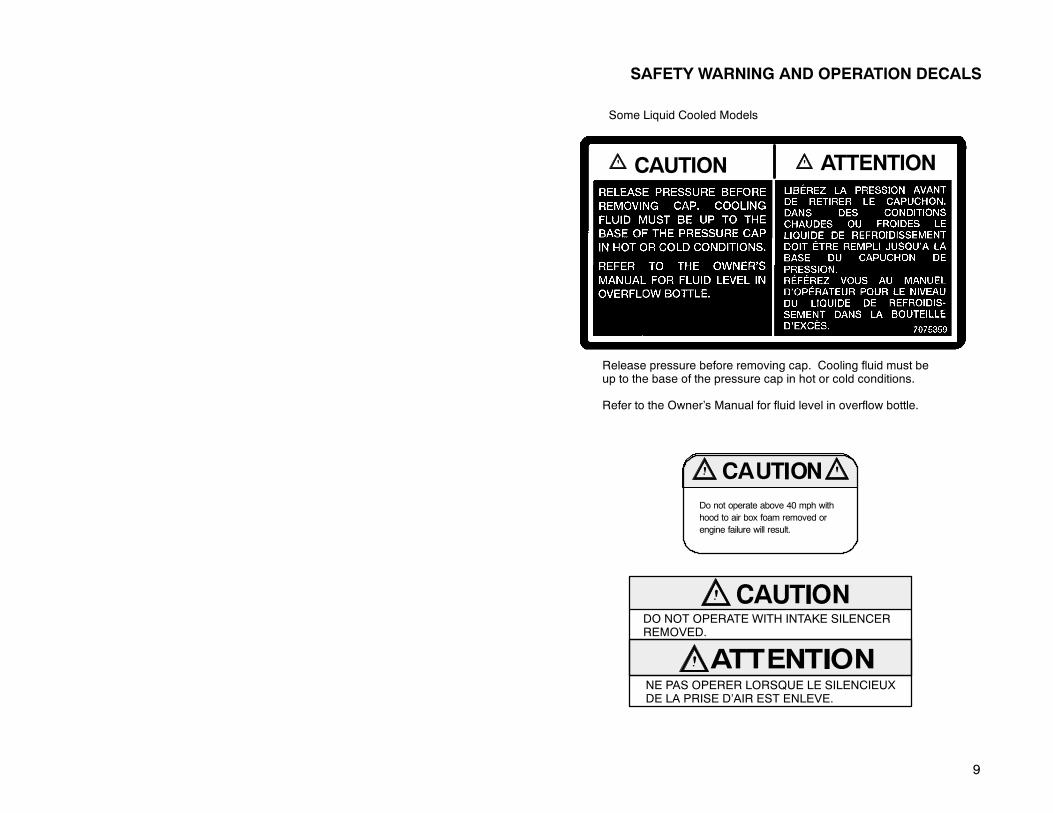
Release pressure before removing cap. Cooling fluid must beup to the base of the pressure cap in hot or cold conditions.
Refer to the Owner’s Manual for fluid level in overflow bottle.
CAUTION ATTENTION
Some Liquid Cooled Models
Do not operate above 40 mph withhood to air box foam removed orengine failure will result.
DO NOT OPERATE WITH INTAKE SILENCERREMOVED.
NE PAS OPERER LORSQUE LE SILENCIEUXDE LA PRISE D’AIR EST ENLEVE.

10
OPERATION WARNINGS
Before Starting The Engine
Read and Understand Your Owner’s Manual
Read the Owner’s Manual completely now, and re-read it occasionally. We haveattempted to provide you with as much information as possible to alert you to thesafety requirements of snowmobiling.
Check Throttle and Brake for Proper Operation
The throttle and brake are the primary controls of your snowmobile. If either shouldmalfunction, a serious loss of control could result.
When checking the throttle, make sure the control lever will compress evenly andsmoothly. When the lever is released, it should immediately return to the idle posi-tion without binding or hesitation. If the throttle does not function smoothly, do notattempt to start the engine. Have the throttle serviced before starting the engine.
The need for a properly functioning brake is vital. This snowmobile is equippedwith the highest quality brake system available. The brake must be checked forcorrect operation before starting the engine. See page 13 for details.
Check for Proper Operation of Steering System
Check for proper operation of the steering system by manually turning the skiscompletely to the right and to the left. If difficulty is encountered, check for ice andsnow buildup which may be obstructing the steering linkage. Make certain allgreasable components are properly lubricated.
Single Rider Snowmobiles
Some Polaris snowmo-bile models are de-signed for a single oc-cupant only. A decal onthe console of thesemodels indicates singleoccupant operation.
WARNING/AVERTISSEMENTThis vehicle is designed for operator only.
“NO PASSENGER”
Ce vehicule est concu pour ne transporterque le conducteur.
“AUCUN PASSAGER”
OR
WARNING/AVERTISSEMENT

11
OPERATION WARNINGS
Driving 2-Up
When operating a 2-Upmachine with a passenger, the driver should be aware thatmore space will be required to make turns, and a longer distancewill be necessaryfor stopping. Lower speeds should be observed whenever riding 2-Up.
CAUTION: Always make certain the passenger remains seated behind the driver,facing forward, with both feet placed firmly on the running boards. Reduce operat-ing speed and be particularly careful to avoid “jumping” your snowmobile.
Some Polaris snowmobile models are designed for two occupants. A decal on thehood of these models indicates that the vehicle is designed for one operator andone passenger only. Machines designated as double occupant should never beoperated with more than two people on board. When traveling with a passengeraboard, it is the driver’s responsibility to operate the machine in a safe manner.Remember that control becomes more difficult with two people on board. Reducespeeds to retain control!
WARNING
Use of a backrest can hin-der operator weight shift-ing. This may affect con-trol of this rider-activevehicle in certain extremedriving situations.
TrackInspection
Driving at wide-openthrottle for extended peri-ods of time in marginal lu-brication could severelydamage track rods, breaktrack edges, and causeother track damage. Ex-amples of marginal lubrication would include lakes without snow cover, icy trailsand no-snow conditions.
Always inspect for damage before using the vehicle. Use of traction products suchas studs, ice growsers, paddles, etc. will increase the possibility of track damageand/or failure. Operating the snowmobile with a damaged track will increase thepossibility of track damage and/or failure, which could cause loss of controlresulting in severe injury or death.
NOTE: Track damage or failure caused by operation on ice or poor lubricationconditions will void the track warranty.
DoNot Operate EngineWith Intake Silencer or FilterRemoved
Whenoperating enginewith intake silenceror filter removed, damage to theenginemay occur.
WARNING/AVERTISSEMENTThis vehicle is designed for operator and
“ONE” passenger only.
Ce vehicule est concu pour ne transporterque le conducteur et “UN SEUL” passager.
WARNING/AVERTISSEMENT
or

12
OPERATION WARNINGS
Stay Clear of Track
During warm-up and operation, stand clear of the rotating track. Do not use toomuch throttle during warm-up or when track is free hanging. Entanglement andserious injury or death may result.
Do Not Operate Engine With Clutch Guard Removed
The clutch guard is designed to protect the operator from metal parts in the eventthe clutch should fail. Although the chance of failure is extremely remote, do notdefeat the purpose of the guard by removing it. It is provided for your safety.
Never Run Engine With Drive Belt Removed
Operation of the engine with the belt removed can result in serious over-speedcondition. Any servicing which requires operation without a belt must be done byyour dealer.
Never Service Clutches Yourself - See Your Dealer
The clutch is a complex mechanism which operates at high rotational speeds.Each clutch is dynamically balanced before installation. Any tampering by theowner may disrupt this precision balancing and create an unstable condition.
Seat Back/Cargo Carrier
Do not sit on seat back or cargo area. Do not exceed carrier and rack weight limits.Cargo load affects machine steering response.
Disabled Operators
Safe operation of this rider-active vehicle requires good judgement and physicalskills. Persons with cognitive or physical disabilities who operate this vehicle havean increased risk of overturns and loss of controlwhichcould result in serious injuryor death.
13
OPERATION WARNINGS
Hydraulic Brakes
The need for a properly functioning brake is vital. Polaris snowmobiles areequipped with the highest quality hydraulic disc brake system available. The fol-lowing itemsmust be checked each time before starting the engine to assure prop-er operation.
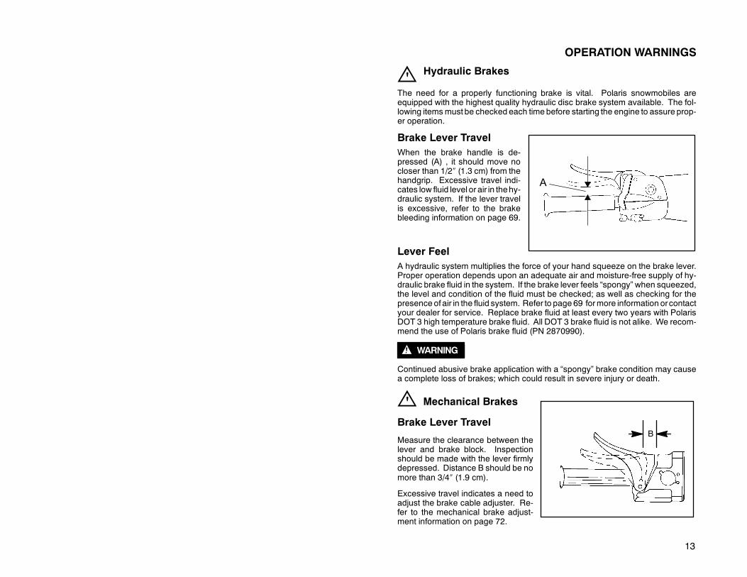
Brake Lever TravelWhen the brake handle is de-pressed (A) , it should move nocloser than 1/2″ (1.3 cm) from thehandgrip. Excessive travel indi-cates low fluid level or air in thehy-draulic system. If the lever travelis excessive, refer to the brakebleeding information on page 69.
Lever FeelA hydraulic system multiplies the force of your hand squeeze on the brake lever.Proper operation depends upon an adequate air and moisture-free supply of hy-draulic brake fluid in the system. If the brake lever feels “spongy” when squeezed,the level and condition of the fluid must be checked; as well as checking for thepresence of air in the fluid system. Refer to page 69 formore information orcontactyour dealer for service. Replace brake fluid at least every two years with PolarisDOT 3 high temperature brake fluid. All DOT 3 brake fluid is not alike. We recom-mend the use of Polaris brake fluid (PN 2870990).
WARNING
Continued abusive brake application with a “spongy” brake condition may causea complete loss of brakes; which could result in severe injury or death.
Mechanical Brakes
Brake Lever Travel
Measure the clearance between thelever and brake block. Inspectionshould be made with the lever firmlydepressed. Distance B should be nomore than 3/4″ (1.9 cm).
Excessive travel indicates a need toadjust the brake cable adjuster. Re-fer to the mechanical brake adjust-ment information on page 72.
A
B

14
OPERATION WARNINGS
Park Brake Lever Lock
1. Brake Handle2. Park Brake Lever Lock
(Not all models areequipped with a parkbrake)
3. Master CylinderReservoir
4. Master Cylinder Cover5. Fluid Level Indicator
Your snowmobile has a brakebrake lever lock. It is locatedover the brake lever. Use thebrake lever lock only when youwant the machine to remainstationary (e.g. when parkedon an incline) for a period offive minutes or less. To applylock, squeeze brake handleand push forward on brake lever lock. Hold lock forward and release brake handle.To release lock, squeeze brake handle until lever returns to the unlock position.The park brake light on the console will be lit when the park brake lever lock is setand the engine is running. It is also lit when the service brake is in use. If the parkbrake light does not come on when park brake or service brake is in use, have itserviced by your dealer.
WARNING
If the park brake lever lock is left partially or entirely engaged while riding the snow-mobile, it could cause overheating of the brakes which could result in damage tothe brake caliper. In extreme cases it could cause a fire which could result in seri-ous injury or death.
Check to See That the Hood is Securely Latched
The hood of the snowmobile protects the operator frommoving parts aswell asaid-ing in sound emission control and various other functions. Under no circum-stances should your snowmobile be operated with the hood open or removed.
1
2 4
53

15
OPERATION WARNINGSAuxiliary Shut-Off Switch
Check auxiliary shut-off switch for proper operation. Push down to stop engine.Pull up to release and start engine.
Tether Switch (accessory on all models)
Check tether switch for proper operation.
Remove Ignition Key
Don’t tempt anyone to steal or ride your snowmobile without permission by leavingthe key in the ignition.
Lighting Check
Check headlight high and low beam, taillight and brake light for normal operation.
Check Surroundings to Verify Clear Operating Area
It is most important to assure yourself that you have a clear area all around yoursnowmobile, including an area clear of bystanders. Remember that the possibilityalways exists of some sideways vehicle movement, or a little more throttle than in-tended; or debris may be thrown by the track. If you are assured of a clear areasurrounding you before you start, you can devote your full attention to operatingthe snowmobile.
Be Seated and in Position to Control the Vehicle
Improper operator position on the snowmobile can be the source of serious injury.Remember that operating a snowmobile does require skill and balance for propercontrol, and an improper position can seriously reduce your ability to control yoursnowmobile. The style of positioning will vary from person to person as they be-come more skilled; but under most conditions the proper position is to be seated,feet on the running boards, and in a comfortable position for proper throttle, brake,and steering control.
WARNING
Your snowmobile is pro-pelled by a revolving trackwhich must be partially ex-posed for proper operation.Serious injuries may becaused by operator care-lessness resulting in hands,feet, or clothing becomingentangled in the track. Bealert. Remember, beingproperly seated keeps youclear of the track.
Never hold the snowmobile up or stand behind it while warming up the track. Aloose track or flying debris could cause serious personal injury or death.

16
OPERATION WARNINGS
Stop Engine Before Attempting Adjustments
WARNING
The snowmobile engine compartment contains moving parts. Shields and guardshave been provided for your safety, but it is still possible to carelessly get yourhands or fingers into amoving belt or a rotating shaft. For this reason neverattemptadjustments with the engine running. Serious personal injuries can result. Theproper method is to turn off the ignition, raise the hood, make the adjustment, se-cure shields and guards, secure the hood, and then re-start the engine to checkits operation. The same is true of track alignment. If the track must be re-aligned,it is recommended that this service be performed by your dealer.
Always Wear Clothing Designed for Snowmobiling
Clothing designed for snowmobiling is warm, comfortable and safe.
WARNING
Always wear an approved helmetand eye protection. Don’t wearloose clothing or long scarves be-cause they can easily become en-tangled in moving parts. Also, beaware of the weather forecast andespecially the wind chill. A table isprovided on page 19 for your refer-ence. Be prepared. Be warm andcomfortable.
Know the Limitations of the Machine and Your Skills as aDriver
D Observe state and local laws governing snowmobile operation. They havebeen established for your protection.
D Traveling at night requires extra caution. Check both headlight and taillight toensure proper operation. Do not “over-drive” your headlight beam. A good ruleto follow is to be able to bring your machine to a stop in the distance illuminatedby the headlight. High speed driving at night is dangerous and unwise, andcould result in severe personal injury or death.
D Be courteous to oncoming traffic by dimming your headlights and lowering yourvehicle speed. Your snowmobile is equipped with a high output head lamp sys-tem that can cause discomfort to operators of oncoming vehicles if the headlightis not dimmed.

17
OPERATION WARNINGS
D Wire fences are a serioushazard. Unless you are thor-oughly familiar with an area,you should always be on thealert for fences. Singlestrands are especially dan-gerous, since there can be agreat distance betweenposts. Guy wires on utilitypoles are also difficult to dis-tinguish. Reduce speedwhen traveling near poles,posts, or other obstacles. Beespecially alert if you aresnowmobiling after dark.
D When travelling on lakes andstreams that are strange toyou, always check with localresidents or authorities forgeneral information on condi-tions. Thin ice, open water,and snowmobiles are notcompatible. Before ridingyour machine on a frozenbody ofwater, be sure that theice is thick enough to supportthe machine and its operatoraswell as the force createdbya moving vehicle. Variancesin snow depth and/or watercurrents can result in unevenice thickness. Use commonsense and good judgment atall times as drowning may re-sult if you and thesnowmobilebreak through the ice.
Ice
Snow

18
OPERATION WARNINGS
D Remember, the sound of your ma-chine will drown out the sound ofapproaching vehicles. Look ahead,behind, and to the sides before turn-ing or crossing railroad crossings orhighways. Steep embankmentsmay also hide your view. Alwaysleave yourself a way out. Makesure the way is clear before youcross railroads and other roads andhighways.
D Drive defensively when traveling in a group of snowmobiles to avoid accidents.Don’t tailgate. Allow ample stopping distances.
D Always be alert and pay attention to the trail ahead of you. Multiplying speed(MPH) by 1.5 will equal the approximate number of feet per second your ma-chine travels. If your speed is 40MPH, yourmachine is travelling approximately60 feet per second. This means that if you look back for only two seconds, yourmachine will travel about 120 feet. If your speed is 60 MPH, your machine willtravel approximately 180 feet in two seconds.
D When teaching inexperienced operators to ride, set up a nearby predeterminedcourse. Make sure they know how to drive and control the snowmobile beforeyou allow them to make longer distance runs. Teach them proper snowmobilecourtesy. Enroll them in a driver’s training and safety course sponsored by alocal or state organization.
19
OPERATION WARNINGS
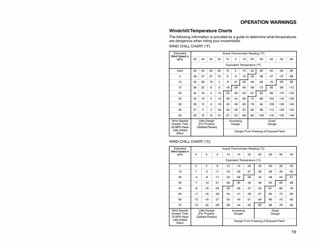
Windchill/Temperature ChartsThe following information is provided as a guide to determine what temperaturesare dangerous when riding your snowmobile.
WIND CHILL CHART (°F)
EstimatedWind Speed in
Actual Thermometer Reading (°F)Wind Speed in
MPH 50 40 30 20 10 0 -10 -20 -30 -40 -50 -60
Equivalent Temperature (°F)
Calm 50 40 30 20 10 0 -10 -20 -30 -40 -50 -60
5 48 37 27 16 6 -5 -15 -26 -36 -47 --57 -68
10 40 28 16 4 -9 -21 -33 -46 -58 -70 -83 -95
15 36 22 9 -5 -18 -36 -45 -58 -72 -85 -99 -112
20 32 18 4 -10 -25 -39 -53 -67 -82 -96 -110 -124
25 30 16 0 -15 -29 -44 -59 -74 -88 -104 -118 -133
30 28 13 -2 -18 -33 -48 -63 -79 -94 -109 -125 -140
35 27 11 -4 -20 -35 -49 -67 -82 -98 -113 -129 -145
40 26 10 -6 -21 -37 -53 -69 -85 -100 -116 -132 -148
Wind SpeedsGreater Than40 MPH Have
Little Danger(For ProperlyClothed Person)
IncreasingDanger
GreatDanger
40 MPH HaveLittle Added
Effect
Clothed Person)
Danger From Freezing of Exposed Flesh
WIND CHILL CHART (°C)
EstimatedWind Speed in
Actual Thermometer Reading (°C)Wind Speed in
KPH 5 0 -5 -10 -15 -20 -25 -30 -35 -40
Equivalent Temperature (°C)
0 5 0 -5 -10 -15 -20 -25 -30 -35 -40
10 1 -4 -11 -16 -22 -27 -33 -38 -45 -50
20 -4 -9 -17 -23 -29 -36 -42 -48 -54 -61
30 -7 -13 -21 -28 -35 -42 -48 -55 -63 -69
40 -9 -16 -24 -32 -39 -47 -53 -61 -69 -76
50 -11 -18 -26 -34 -41 -49 -57 -64 -73 -80
60 -12 -19 -27 -35 -43 -51 -59 -66 -75 -82
70 -13 -20 -28 -36 -44 -52 -60 -68 -76 -84
Wind SpeedsGreater Than70 KPH Have
Little Danger(For ProperlyClothed Person)
IncreasingDanger
GreatDanger
70 KPH HaveLittle Added
Effect
Clothed Person)
Danger From Freezing of Exposed Flesh

20
OPERATION WARNINGS
Cold Weather Driveaway
Whenever the machine has been parked for some length of time, especially over-night, always shake loose the skis and track before attempting to put the machineinto motion. The throttle should always be opened with enough authority to put themachine into motion, staying within safety limits and with respect to a passenger,on a two passenger machine.
Powder Snow OperationYour Polaris is designed to operate best on snow. Maneuverability is attained bythe steering, skis, and the shifting of your body weight. Maximum control will beattained by shifting body weight. Maneuverability will change for lighter operatorsor machines carrying a load or a passenger where allowed.
CAUTION: Do not operate for prolongedperiods onblacktop,gravel, or glare ice.
It is essential that yourmachine be operated under conditionswith adequate snowcover, as snow provides the only lubrication for the power slide suspension and,on liquid cooledmodels, cooling for the engine. Failure to do sowill result in exces-sive wear and damage to the slide rail and track and/or engine.
If the machine becomes stuck in snow, free the running board area, and step downthe snow in front of the machine so that when the throttle is opened the machinewill be able to climb up and over. The operator can then mount the machine andcontinue.
WARNING: Snow and ice buildup in the underhood area cancause interference with the steering function.
Before driving, be sure that ice and snow are not interfering with full left and rightsteering bymanually turning the skis to the left and right. If difficulty is encountered,check for ice and snow buildup which may be obstructing the steering linkage.Snow screen and bib kits are available through your dealer to help reduce snowand ice buildup.
NOTE: The ability of the machine to travel in adverse conditions will improve asthe operator gains experience.

21
OPERATION WARNINGS
Hard Packed Snow
WARNING
Steering and braking control are substantially reduced underpacked snow or icy conditions.
Excessive shifting of operator body weight when turning on hard packed snow orslippery surfaces can result in loss of vehicle control and serious injury. Reducespeed as required to maintain control under these conditions.Ice
It is dangerous to operate on ice or under slippery conditions. If ice or slip-pery conditions are unavoidable, use extreme caution and operate at
speeds no faster than a walk. Never attempt an abrupt change of direction on aslippery surface. The chance of “spin-out” increases under these conditions.
Before riding your snowmobile on a frozen body of water, be sure that the ice isthick enough to support the machine and its occupant(s) as well as the force thatis created by amoving vehicle. Severe injury or death can result if the snowmobileand/or its occupant(s) break through the ice.

22
OPERATION WARNINGS
Hilly Terrain
Exercise caution and good judgement when travelling in hilly terrain.
Crossing a Slope (Sidehilling)
WARNING
Sidehilling can be very dangerous and is not recommended for inexperiencedsnowmobilers.
Crossing the face of a slope (sidehilling) requires the operator to position his/herweight in order to maintain proper balance. Kneel with the knee of the downhill legon the seat and the foot of the uphill leg on the running board. This position makesit easier to shift your weight as needed. As you travel across the slope, lean uphillto position your weight on the uphill side.
23
OPERATION WARNINGS
Riding Uphill
Hill climbing may be accomplished by using one of twomethods, depending uponthe steepness of the hill.
Sidehillingmay be used if there are few obstacles on the hill. The operator shouldassume a kneeling position (as in Sidehilling), keeping body weight on the uphillside at all times. Maintaining a steady, safe speed, approach the hill at an angle,continuing as far as possible in this direction; then switch to the opposite angle andriding position.
The direct climb method requires extreme caution. The operator should assumea standing position with body weight kept low and forward, accelerating before thestart of the climb and then releasing throttle pressure enough to prevent track slip-page.
In either type of climb, the operatormust slow down when reaching the crest of thehill. Be prepared to react to obstacles, sharp drops, or other people or vehicleswhich may be on the other side of the hill.
If you are unable to continue up a hill, turn the machine downhill before itloses momentum. If this is not possible, spin the track just enough to dig
in so themachine won’t roll back down the hill. Stop the engine and set the parkingbrake (if equipped). Keeping away from the downhill side of the machine, pull therear of the snowmobile around, pointing the machine back downhill. Once thesnowmobile is pointed downhill,mount themachine, restart theengine, release theparking brake, and descend the hill.
Riding Downhill
When riding downhill, keep speed at a minimum. It is important to apply justenough throttle to keep the clutchengagedwhiledescending thehill. This will allowuse of the engine’s compression to help slow themachine, and keep the snowmo-bile from rolling freely downhill.
WARNING
Use extreme caution when applying the brake during a descent. Excessive brak-ing will cause the track to lock, resulting in loss of control.

24
OPERATION WARNINGS
Responsible DrivingIf you operate the snowmobile improperly, you will cause situations which will ex-ceed your driving skills. Each snowmobile handles differently, and even if you area seasoned driver, it is strongly recommended that you spend some time gettingthe feel for this particular machine before attempting ambitious maneuvers. If youare new to snowmobiling, take enough time to acquaint yourself with the machineand what it will and won’t do under various conditions.
Acquire a feel for your machine before attempting ambitious maneuvers.The snowmobile depends on your body position for proper balance in
executing turns, traversing hills, etc. It’s best to start on a smooth level area to be-gin building your operating experience.
Before you let someone else use your snowmobile, be sure you know theextent of their operating skills. Check to see if they have taken a snowmo-
bile safety course and have an operator’s certificate. For their protection, as wellas yours, make sure they take a snowmobile safety course. Everyone can benefitfrom the course.
Don’t “jump” your snowmobile. Jumping can injure your back because ofspinal compression. The seat and suspension of your snowmobile have
been designed and constructed to give you protection, but they do have limits.Your snowmobile is not intended for this kind of use.

25
PRESERVATION OF THE ENVIRONMENT
We recommend that you drive your snowmobile with consideration for the protec-tion and preservation of our environment.
Noise Level
Probably themost publicized subjectwith regard to snowmobiles is noise. TheSo-ciety of Automotive Engineers (SAE), which is the standard-setting body for snow-mobiles, has recommended that snowmobiles conform toprescribed sound levels.Your Polaris snowmobile has been engineered to conform to these SAE stan-dards.
In order to bemeaningful, all regulations require the cooperation of thesnowmobiledriver. Muffling systems, designed to reduce noise levels, should not be alteredor removed. Snowmobile drivers must be aware that they have a public responsi-bility to operate their snowmobiles with concern for others. As a snowmobile oper-ator you may not realize the sound of your snowmobile may annoy non-snowmo-bilers. We are attempting to do our part through the manufacture of quietermachines, and we also ask your help in the effort to further reduce the impact ofnoise.
Air Pollution
As a part of Polaris’ plan for the snowmobile’s compatibility within the environment,our engineers are investigating ways to reduce emission levels of two-stroke en-gines. We expect our efforts to lead to the reduction of potential air pollution.
In addition to technological research, we also suggest that governmental agen-cies, manufacturers, distributors, dealers, ecologists, and other interested partieswork together to develop data on environmental topics. We will continue to partici-pate in this type of study so that someday wemay find the answers to these difficultissues.
Environmental Protection
As part of the continuing environmental education campaign, we are encouragingstate and provincial governments across the snowbelt to adopt rigorous safetytraining programswhich also encourage protection of ourenvironment,wildlife andvegetation. Snowmobile clubs and other organizations are working together toprotect our environment. It is very important that we encourage them as well asbecome actively involved ourselves.
Respect your snowmobile;respect your environment;
and you will earnthe respect of everyone.

26
IDENTIFICATION AND SPECIFICATIONS
Vehicle Nomenclature
Refer to illustrations on following pages. NOTE: Illustrations are a general repre-sentation. Your model may differ.
1. Hood 13. Suspension2. Headlight 14. Nosepan3. Windshield 15. Trailing Arm4. Handlebar 16. Skis5. Seat 17. Front Bumper6. Storage/Rear 18. Console7. Taillights 19. Vehicle I.D. Number (Right Side)8. Backrest 20. Rear Bumper9. Tunnel Extension 21. Passenger Hand Hold10. Passenger Hand Hold Strap 22. Lifting Hand Hold11. Track 23. Snow Flap
24. Mountain Bar
Vehicle Nomenclature, Cont.
2
1
3
45 6
7
8
9
10
1113
19
1415
16
17
22
23
20

27
IDENTIFICATION AND SPECIFICATIONS
Vehicle Nomenclature, Cont.
23
111319151416
65
4
18
3
2
122
11 23131915
14
16
17
1
2
3
4
510
8
9
18
6
22
7
20
8
18
17

28
IDENTIFICATION AND SPECIFICATIONS
Vehicle Nomenclature, Cont.
2
1
3
4 5
67
11131914 15
16
17
23
20
24

29
IDENTIFICATION AND SPECIFICATIONS
Controls and Instruments
1. Headlight Dimmer Switch (2Position)
2. Fuel Filler Cap/Gas Gauge3. Auxiliary Shut-Off Switch
(Push/Pull). Operation foundon page 40.
4. Throttle Control5. Recoil Starter Handle6. Choke Control7. Ignition Switch8. Tachometer (may include indicator
/ warning lights)9. Speedometer (may include indi-
cator / warning lights)10. Brake Lever11. Low Oil Warning,Brake Light,
High Beam, Temp, premium fueloptions
12. Accessory Indicators13. Safety Decals14. Hood Hold Down15. Handlebar Grip Warmer Switch16. Thumbwarmer Switch17. Thumbwarmer/Handwarmer
Switch18. Reverse Lever19. Fuel Gauge20. Temperature Light21. Tether Switch22. Power Plug23. Electric Shock Absorber Gauge
310
1119 20
138
462 7
1
16 15
General RepresentationsYour Model May Differ
9
1 3
13
47
2
1412
17
6
10
13
98
10
15
161
27 21 6 22 18
5
4
3
9
2320

30
IDENTIFICATION AND SPECIFICATIONS
Backrest1. Backrest Cushion Adjuster2. Backrest Adjuster Cable3. Grab Bar Adjustment Knob4. Passenger Handwarmer Switch5. Wind Deflector6. Backrest Adjustment Lever7. Passenger Hand Hold
1
2
3
4
5
6
7

31
OPERATION
Carburetion
Proper carburetor adjustment is critical, since a mixture too lean (toomuch air, toolittle fuel) will result in overheating of the combustion chamber causing pre-ignitionof the fuel. This results in piston burning, bearing failure, or complete engine fail-ure. A lean mixture can be the result of fuel line restrictions, foreign matter in thecarburetor, clogged fuel filter, etc.
A mixture too rich (too much fuel, too little air) is also unfavorable because it canfoul plugs and cause generally poor engine performance.
All carburetors have been pre-set at the factory for adequate fuel supply. Higheraltitude operation may require different adjustment and settings.
RMKmodels are pre-set to operate at altitudes of 6000-9000 feet above sea level.
WARNING
Carburetor adjustments must be performed by your dealer, sincemistakes can re-sult in possible operator safety hazards as well as serious engine damage.
Remember, correct setup provides engine RPM within its given power band at fullthrottle settings and also provides maximum efficiency and operation at all otherthrottle openings. Your dealer has the training and tools required to perform anyadjustments for you.
WARNING
Engine damage may result if jetting or clutching is wrong. Never service clutchesyourself. See your dealer.
Drive System
1. Engine2. Torque Converter
(Drive Clutch)3. Driven Clutch4. Drive Belt
(Neutral Position)5. Drive Belt
(Full Upshift Position)6. Upper Chaincase
Sprocket7. Chain8. Lower Chaincase
Sprocket9. Chaincase Oil Level10. Drive Shaft11. Track
1
2
34
5
6
7
8
9
10
11
32
OPERATION
LubricationThe fuel and oil which enter the engine through the fuel and oil injection systemsprovide the only source of engine lubrication, and must be of the highest quality.
You can understand the importance of proper lubrication when you realize that at6000 RPM the crankshaft is rotating 100 revolutions per second.
Premium 2-Cycle LubricantThe only oil recommended for this fuel system is Polaris brand oil. CAUTION: En-gine warranty coverage may become void if other brands are substituted.
Polaris Premium Gold Synthetic Lubricant is the most advanced formulation of oilavailable for today’s 2-cycle engines. Over twenty months of lab and field testshave resulted in a new generation of 2-cycle lubricant. Polaris Premium 2-CycleLubricant addresses the problem of lower quality fuel; keeping ring grooves clean-er with less ring sticking and providing improved overall engine cleanliness. Withnew generation lubricity technology, it excels in meeting the lubricity demands oftoday’s faster,more precisely engineered 2-cycle engines. It is theoptimumoil rec-ommended for liquid 2-cycle engines and performswell in all air cooled 2-cycle en-gines. We believe this oil is the best product available in the market today, andstrongly recommend its use in all of our products.
Never mix other brands of oil since they may be incompatible, resulting in sludgeformation, filter blockage and reduced cold weather flow rates.
Oil Injection SystemThe fuel-to-oil mix ratios are controlled by the oil pump and the movement of theoil pumparm. The fuel-to-oilmix ratio corresponds to the engine’sRPMand throttlevalve opening.
Always fill the oil reservoir when refueling.
NOTE: Mix two pints ofPolaris injection oil to the first tankfulof gasoline. Inadditionto the lubrication supplied by the injection system, this will ensure proper enginebreak-in.
CAUTION:
Check the oil tank level often during the first tankful of fuel. If the oil level doesn’tgo down, contact your dealer immediately. Continue using premixed fuel until theoil injection system can be inspected.
Low Oil Indicator LightThe low oil indicator light is standard on most models.
CAUTION:
When the low oil indicator light is on, it indicates that oil must be added before fur-ther operation of the snowmobile. Visually check the oil level in the bottle. The en-gine can be operated as long as oil is visible in the oil tank. If oil is not visible, con-tinued operation may cause severe engine damage.

33
OPERATION
WARNING
Never mix brands of two cycle oil. Serious chemical reactions can occur, causinginjection system blockage resulting in severe engine damage and voiding of en-gine warranty.
CAUTION:
Always maintain the oil level in the oil tank above the low level line. The low oil indi-cator light will indicate when to add oil. However, the oil level should always bechecked when refueling. NOTE: In the illustration, * indicates low oil level.
This is especially important when the machine is operated in mountainous terrain.Maintaining the proper oil level will prevent system aeration and possible loss ofpumping action, which could result in engine damage.
NOTE: Always use a Polaris oil cap, never substitute. Your Polaris oil cap maybe vented to allow proper oil flow.
*At low level mark add 1 U.S. quart.
*
*
NOTE: Not all modelshave a coolant bottle at-tached to the oil tank.

34
OPERATION
Fuel
WARNING
Gasoline is extremely flammable and explosive under certain conditions.
Always stop the engine and refuel outdoors or in a well ventilated area.
Do not smoke or allow open flames or sparks in or near the area where re-fueling is performed or where gasoline is stored.
Do not overfill the tank. Do not fill the tank neck.
If you get gasoline in your eyes or if you swallow gasoline, see your doctorimmediately.
If you spill gasoline on your skin or clothing, immediately wash it off withsoap and water and change clothing.
Never start the engine or let it run in an enclosed area. Gasoline poweredengine exhaust fumes are poisonous and can cause loss of conscious-ness and death in a short time.
WARNING
The engine exhaust from thisproduct contains chemicals
known to cause cancer, birth de-fects or other reproductive harm.

35
OPERATION
FuelThe fuel used in the Polaris engine is as important to engine life and performanceas the lubricant used.
Most Polaris engines are designed to run on 87 octane non oxygenated or 89 oc-tane oxygenated pump gasoline. There is a great deal of variability in the qualityof the 87 octane gasoline available across the country. We encourage the use ofpremium fuel when possible. NOTE: XCR models require premium gasoline.
Consult your Owner’s Manual Supplement for specific minimum octane require-ments.
Premium Fuel SwitchSome Polaris snowmobiles areequipped with a key function that willadjust the timing on the machine asyou change fuels.
Most high performance machines re-quire the use of premium fuels. Whenpremium fuel is not available, there is arisk of engine damage when otherfuels are substituted.
When using fuels with a pump postedoctane rating of 91 or higher, turn thekey switch to “ON/PREM”. When theengine is started a yellow “PremiumFuel” light illuminates on the instru-ment panel. When the key is in thisposition, the fuel must be a minimumof 91 octane.
If you are uncertain about the quality or octane rating of the fuel you are using, turnyour key switch to “ON/REG”. The “Premium fuel” light will go out. This setting willadjust the timing of your engine to run on fuels with 87 octane or higher. Polarisdoes not recommend using fuel with lower than 87 octane.
Running yourmachine on “ON/REG”will protect your engine from damage causedby low octane fuels. It is very important to the life of your engine that you are awareof and use this feature.
Premium Fuel Setting
Regular Fuel Setting
36
OPERATION
Fuel Reserve Capacity
On equipped models, when the fuel gauge reads “RES”, there are approximately2 gallons of fuel left in the tank.
Fuel System Deicers
If you are using non-oxygenated fuel, Polaris recommends the regular use of Iso-propyl base fuel systemdeicer (Polaris PN2870505). Add 1 to 2 ounces per gallon(8-16 milliliters per liter) of gasoline to prevent engine damage resulting from fuelsystem icing and leanmixtures. Never use deicers or additives that containmetha-nol. Use only isopropyl fuel system deicers.
If using oxygenated fuel containing ethanol, additional alcohol deicers or water ab-sorbing additives are not required and should not be used.
CAUTION:
Prolonged exposure to petroleumbased productsmay damage paint. Always pro-tect painted surfaces when working with fuel.
It is recommended that plastic side panels be removed whenever servicing re-quires tipping the machine on its side for a period of fifteen minutes or more.
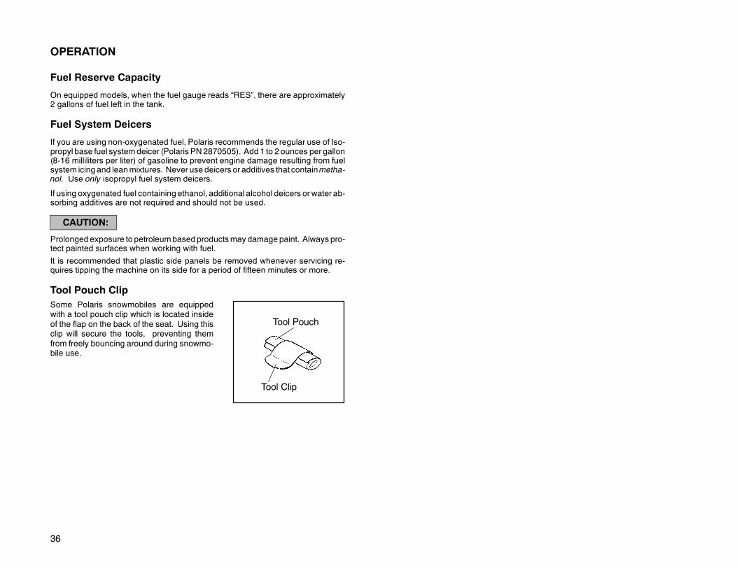
Tool Pouch ClipSome Polaris snowmobiles are equippedwith a tool pouch clip which is located insideof the flap on the back of the seat. Using thisclip will secure the tools, preventing themfrom freely bouncing around during snowmo-bile use.
Tool Pouch
Tool Clip

37
OPERATIONEngine Break-In
No single action on your part is as important to long, trouble-free machine life asproper break-in for a new or rebuilt engine. Familiarize yourself and others with thefollowing procedure for your Polaris snowmobile.
Premix the first tank of gasoline with one pint of Polaris injection oil for each 5 gal-lons of fuel. This, in addition to the lubrication supplied by the injection system, willassure proper engine break-in. IMPORTANT: Before operatingwith unmixed fuel,make sure oil is being drawn from the oil tank.
WARNING
D Never mix brands of two cycle oil. Serious chemical reactions can cause injec-tion system blockage, resulting in severe engine damage and voiding of enginewarranty. The only oil recommended for this system is Polaris injection oil. Thisoil has been specially formulated for all temperatures and has extreme cold flowcharacteristics.
D Donot operate at prolonged full throttle for the first threehours ofoperation. Varythe throttle openings and machine speeds. This will reduce friction on all closefitting machined parts and allow them to break in slowly without damage.
D Avoid operating on ice or hard-packed surfaces, roads, etc. The absence of lu-brication and cooling by snow will lead to overheating of the slide rail and trackresulting in premature wear and failure. Reduce speeds and frequently driveinto fresh snow to allowadequate cooling and polishing of the slide rail and tracksurfaces.
D Drive with extra caution during the break-in period. Perform regular checks onfluid levels, lines, and all important areas of the machine.
With a basic understanding of how the snowmobileworks, andwith close attentionpaid to maintenance tips, you will be ready to ride. Keep in mind these recommen-dations as well as those covered throughout this manual.

38
OPERATION
Pre-Starting
WARNING
Before starting the engine, always refer to all safety warnings pertaining to snow-mobile operation. Never start your snowmobile without checking all componentsto be sure of proper operation. See Operation Warnings beginning on page 10.
Important safety items include, but are not limited to:
D Throttle systemD Brake systemD Steering system
These systems must be checked each time before starting the engine. Incorrectadjustments, damage, or excessive wear due to neglect could result in personalinjury and/or damage to the snowmobile.
Starting a Cold Engine (Manual Start)1. Turn key to “On”.
2. Pull kill switch (shut-off switch) up to “run” position.
3. Flip choke toggle to “Full On” position.
4. Grasp starter handle and pull slowly until recoil engages; then pull to start.
CAUTION:
Do not pull the starter rope to its full extended position or allow it to snap back intothe housing as damage can result.
NOTE: Do not depress throttle until engine starts.
5. After engine starts, the choke toggle should be flipped to “Off” position. If theengine slows or wants to stop, intermittent choking to the “Half On” position ishelpful.
Starting a Cold Engine (Electric Start)
1. Flip choke toggle to “Full On” position.
2. Pull kill switch (shut-off switch) up to “run” position.
3. Turn key to “Start” position and crank engine.
4. After engine starts, release key to “On” positionand flip choke toggle to “Off”. Ifthe engine slows orwants to stop, intermittent choking to the “HalfOn”positionis helpful.
NOTE: Do not depress throttle until engine starts.

39
OPERATION
Starting a Warm Engine1. Turn key to “On”.
2. Pull kill switch (shut-off switch) up to “run” position.
3. Grasp starter handle and pull slowly until recoil engages; then pull to start.
If the engine does not start on the first pull, slightly depress the throttle with yourleft hand (nomore than 1/4″ open), and pull the rope with your right hand. As soonas the engine starts release the throttle.
CHOKE TOGGLE POSITIONS
Off or
Half On or
On or

40
OPERATION
Auxiliary Engine Shut-Off SwitchTo stop the engine in an emer-gency, push down on the auxilia-ry shut-off switch (A). This willground out the ignition and bringthe engine to a quick stop. To re-start the engine the switch mustbe pulled up to the “On” position.
Throttle Safety SwitchTest the throttle safety switchsystem on a daily basis beforethe machine is used.
While seated in a normal ridingposition, and with the engine id-ling, hold the throttle lever pinstationary by exerting pressureon the pivot pin in the directionshown in the illustration (B). Ap-ply a slight amount of throttleopening. A properly functioningswitch must shut down the en-gine.
The throttle safety switch is designed to stop the engine whenever all pressure isremoved from the throttle lever and the throttle cable or valves do not return to thenormal closed position.
WARNING
If the throttle safety switch does not shut off the engine in the event of a carburetor/throttle system malfunction, immediately push down the auxiliary shut-off switch.Do not start the engine until the malfunction has been corrected by your dealer.
If the snowmobile engine stops abruptly when the throttle lever is released, use thefollowing procedure.
1. Turn the ignition switch to “Off”.
2. Visually inspect the throttle cable and carburetor(s) to determine what causedthe safety switch to activate.
3. Test the throttle lever by compressing and releasing it several times. The leverand cable must return to the idle position quickly and completely.
A
B
41
OPERATION
WARNING
If the throttle lever does not work properly, do not start the engine.
4. If the throttle lever operates properly, turn the ignition switch on and go throughnormal starting procedures.
5. If the engine does not start, take the snowmobile to an authorized Polarisdealer for service.
If excessive play develops in the throttle cable, the safety switch may be activated,preventing the engine from starting. Contact your dealer.
If the engine does not start, and throttle safety switch malfunction is suspected, re-turn themachine to an authorizedPolaris dealer for service. Ifan emergencyexistsand it is necessary to start the engine, the throttle safety switch and auxiliary shut-off switch may be disconnected from the wire harness.
WARNING
With the throttle safety switch and auxiliary shut-off switch disconnected, the igni-tion key switch must be used to shut off the engine. Do not continue to operate themachine with the throttle safety switch disconnected. Return the machine to anauthorized Polaris dealer for service as soon as possible.

42
OPERATION
Emergency Stopping ProceduresThe following chart lists methods for stopping the engine in the event of an emer-gency.
SYSTEM WHAT IT DOES THROTTLECONDITION
Ignition Switch Interrupts ignition circuit All
Brake Slows drive shaft All
Choke Floods engine 1/2 throttle or less
Auxiliary Shut-Off Switch Interrupts ignition circuit All
Throttle Safety Switch Interrupts ignition circuit All
Tether Switch (Option) Interrupts ignition circuit All
Refer to page 40 for more information on the auxiliary shut-off and throttle safetyswitches.
Emergency Starting ProcedureYour machine comes with a tool kit containing essential tools for emergency use.In the event the recoil starter system should fail, take the emergency start strapfrom the kit and proceed as follows:
1. Open clutch guard.2. Push on the inner sheave
of the secondary clutchandrotate clockwise slightly torelieve belt tension. Thisallows for easier starting.
3. Starting at one of the towerstruts, wind the strapcounterclockwise aroundthe clutch as shown.
WARNING
Do not wind the strap around your hand. Severe injury could result.
4. Pull the strap using a sharp, crisp pull so the strap comes free of the clutch.
CAUTION:
Keep all people clear of the snowmobilewhen using the emergency starting proce-dure.

43
OPERATION
Pre-ride Warm Up
The following steps must betaken to ensure proper warmup of the engine, drive train andtrack.
With the snowmobile securelysupported by the rear bumper,and approximately 4″ (10 cm)off the ground, use the follow-ing procedure.
1. Start the engine and allowit to warm up two to threeminutes.
WARNING
Be sure the rear support is stable. Stand clear of the front of the machine and themoving track. Never hold the snowmobile up or stand behind it while performingthis procedure. Do not use too much throttle during warm up or when track is free-hanging. A loose track or flying debris could cause serious personal injury ordeath.
2. Engage the drive system abruptly and allow it to rotate the track severalrevolutions. NOTE: The outside temperature will determine the amount oftrack warm-up required.
3. Shut off the engine and remove the rear support.
4. Grasp the skis by their front loops andmove from side to side. This will loosenfrozen snow from the ski bottoms, allowing themachine tomove forwardmoreeasily.
5. The engine, drive system and track are now properly warmed up and themachine can be driven following normal safety practices.
6. WideTrak models can also be warmed up with the transmission in neutral andthe brake engaged. This will allow the engine to warm without engaging thedrive system. NOTE: This should not last more than five minutes.
WARNING
Engine RPM should be at idle before shifting the transmission.

44
OPERATION
Towing
WARNING
For your safety, the proper function of a tow hitch must be understood before at-tempting its use.
Do not tow toboggans, sleds, saucers, or any type of vehicle with a rope. No brak-ing power can be applied to an object being towed with a rope.
Only a stiff metal pole connecting the towed object and tow hitch on the snowmo-bile should be used. If passengers are to be towed on a toboggan or sled, ensurethat the stiff connecting pole is at least four feet (1.2 meters) long to prevent anypossibility of contact between the vehicle track and a person riding in the towedobject.
Reduced speeds are required when towing to aid in maintaining steering and gen-eral vehicle control. Braking ability is also reduced when towing loads. Reducespeed and use caution, as braking distances will increase. Tipover can occur re-sulting in severe injury or death.
If a situation arises requiring the snowmobile to be towed by another snowmobile,attach the tow rope to the spindles, not the ski loops.
WARNING
Always remove the drive belt from a disabled snowmobile or shift the transmissionto neutral before towing to prevent serious damage to the engine and drive system.
Daily Storage
Whenever your machine is placed in overnight or daily storage the following stepsmust be taken:
D Park the snowmobile on alevel surface and support itat the rear so the track is sus-pended approximately 4″(20 cm) off the ground.
D Remove the key and coverthemachine using the Polar-is cover available for yourmodel. See your dealer formore information.

45
BATTERY
Battery Fluid
Apoorlymaintained battery willdeteriorate rapidly. Check thebattery fluid level often. Thefluid level should be kept be-tween the upper (1) and lower(2) level marks.
To refill use only dis-tilled water. Tap water
contains minerals which areharmful to a battery.
Battery ConnectionsBattery terminals and connections should be kept free of corrosion.
If cleaning is necessary, remove the corrosion with a stiff wire brush. Wash termi-nals and connections with a solution of one tablespoon baking soda and one cupwater. Rinse well with tap water and dry with clean rags. Coat the terminals withdielectric grease or petroleum jelly.
Do not allow cleaning solution or tapwater toenter thebattery. It will shortenthe life of the battery.
WARNING
Battery electrolyte is poisonous. It contains acid!Serious burns can result from contact with the skin, eyes, or clothing.
ANTIDOTE:
EXTERNAL: Flush with water.INTERNAL: Drink large quantities of water or milk. Follow with milk of mag-nesia, beaten egg, or vegetable oil. Call physician immediately.EYES: Flush with water for 15 minutes and get prompt medical attention.Batteries produce explosive gases. Keep sparks, flame, cigarettes, etc.away. Ventilate when charging or using in closed space. Always shieldeyes when working near batteries.KEEP OUT OF REACH OF CHILDREN.
2
1

46
BATTERY
Battery Removal
CAUTION:
Whenever removing or reinstalling the battery, disconnect the negative (black)cable first and reinstall the negative cable last to avoid the possibility of explosion.
1. Disconnect hold down straps holding battery in position.2. Remove battery vent tube from battery.3. Disconnect black (negative) battery cable first.4. Disconnect red (positive) battery cable second.5. Lift the battery out of the snowmobile, being careful not to tip it sideways or spill
electrolyte.
CAUTION:
If electrolyte spills, immediately wash it off with a solution of 1 tablespoon bakingsoda and one cup water to prevent damage to the snowmobile.
When your snowmobile is placed in storage for one month or more:
D Remove the battery.D Charge it to the proper level.D Store it in a cool dry place.
It is possible for batteries to freeze at the following charge conditions, resulting incell damage.
D 100% Charged -75° F (--59° C)D 75% Charged -24° F (--31° C)D 50% Charged 0° F (--18° C)D 25% Charged +13° F (-11° C)D 0% Charged +18° F (--8° C)
Before using the battery, take it to your dealer for testing and recharging.

47
BATTERY
Battery Installation
WARNING
To avoid the possibility of explosion, always connect battery cables in the orderspecified. Red (positive) cable first, black (negative) cable last.
1. Set the battery in its holder. Attach the hold down strap.
2. Install the battery vent line. It must be free from obstructions and securelyinstalled. Route the vent line away from the frame and body to preventcorrosion.
WARNING
If the battery vent tube is pinched or kinked, battery gases could accumulate result-ing in an explosion. Avoid skin contact with electrolyte as severe burns can result.
3. Connect and tighten the red (positive) cable first.
4. Connect and tighten the black (negative) cable last.
5. Verify that cables and vent hose are properly routed.
48
MAINTENANCE
Polaris Recommended Owner Maintenance Program
YourPolaris snowmobile has been engineered andmanufactured by skilled Polar-is personnel to the highest degree of performance and reliability possible. In ordertomaintain this high degree of performance and reliability your Polarismust be giv-en regular service and maintenance inspections.
We are interested in ensuring your continued enjoyment in snowmobiling with Po-laris. To assure you of trouble-free enjoyment, the Polaris Owner MaintenanceProgram has been developed. If the recommended regularmaintenance and ser-vice checks are followed, you will be doing your part in keeping your snowmobilein excellent operating condition at all times.
The recommended maintenance schedule on your snowmobile calls for a serviceand maintenance inspection at 150 miles (240 km), 1000 miles (1600 km), and2000 miles (3200 km). These inspections should be performed by a qualified ser-vice technician. All necessary replacement parts and labor incurred, with the ex-ception of authorized warranty repairs, become the responsibility of the registeredowner.
If during the course of the warranty period parts failures occur as a result of ownerneglect in performing the recommended periodicmaintenance, the cost of such re-pairs shall be borne by the owner. Please consider the recommended mainte-nance program illustrated on the following pages as a preventative maintenanceprogram designed to maintain the performance and reliability of your snowmobilein the years to follow.
Weekly Maintenance Check
For best machine performance and safe operation, check these pointsweekly and before any long distance trip:
1. Track alignment and adjustments2. Chain (if applicable)3. Gearcase oil level (if applicable)4. Drive chain tension (rotate driven clutch back and forth, checking for
excessive deflection)5. Drive belt condition/tension6. Brake operation, adjustment (Mechanical), fluid level (Hydraulic)7. Headlights, tail and stop lights8. Emergency shut off switch operation and throttle safety switch function9. Suspension mounting bolts (tighten)10. Steering arm and tie rod ends (check for play or looseness)11. Ski saddle and spindle bolts (tighten)12. Suspension front limiter strap bolts (tighten)13. Condition of front limiter strap14. Throttle cable condition15. Coolant level16. Battery fluid level

49
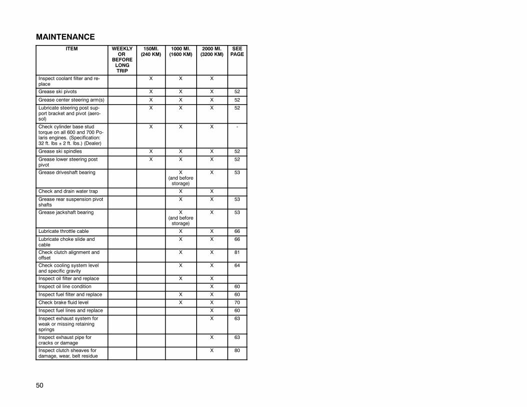
MAINTENANCECareful periodicmaintenancewill help keepyour vehicle in thesafest,most reliablecondition. Inspection, adjustment and lubrication of important components are ex-plained on the following chart and maintenance pages of this manual.
For continued maximum machine performance and component life, it is recom-mended that maintenance checks be performed at 1000 mile (1600 km) intervals.
Service and adjustments are critical. If you are not familiar with safe service andadjustment procedures, have a qualified dealer perform these operations.
NOTE: The following chart is aguide basedon average riding conditions. Youmayneed to increase frequency based on riding conditions. Inspection may reveal theneed for replacement parts. Always use genuine Polaris parts available from yourPolaris dealer.
ITEM WEEKLYOR
BEFORELONGTRIP
150MI.(240 KM)
1000 MI.(1600 KM)
2000 MI.(3200 KM)
SEEPAGE
Check brake operation andadjustment
Daily 69
Test auxiliary shut-off switch Daily 40
Test throttle safety switch Daily 40
Throttle lever operation Daily 10, 40
Check track alignment X 92
Check track tension X 90
Check chaincase oil level X 67
Check gearcase oil level X 68
Check drive chaintension
X 67
Check drive belt condition X 80
Check operation of head-lights, taillight, brakelight
X 1575
Check and tighten loose sus-pension mounting bolts
X 101
Tighten ski saddle andspindle bolts
X 101
Check front limiter strapcondition, tighten bolts
X 126
Check ski skags- replacewhen worn to 1/2 original di-ameter
X 100
Check hi-fax thicknessReplace when worn (Dealer)
X 101
Tighten rear idler wheel bolts X 92
Tighten idler adjusting boltjam nuts
X 92
Check spark plug condition X 56
50
MAINTENANCEITEM WEEKLY
ORBEFORELONGTRIP
150MI.(240 KM)
1000 MI.(1600 KM)
2000 MI.(3200 KM)
SEEPAGE
Inspect coolant filter and re-place
X X X
Grease ski pivots X X X 52
Grease center steering arm(s) X X X 52
Lubricate steering post sup-port bracket and pivot (aero-sol)
X X X 52
Check cylinder base studtorque on all 600 and 700 Po-laris engines. (Specification:32 ft. lbs ± 2 ft. lbs.) (Dealer)
X X X -
Grease ski spindles X X X 52
Grease lower steering postpivot
X X X 52
Grease driveshaft bearing X(and beforestorage)
X 53
Check and drain water trap X X
Grease rear suspension pivotshafts
X X 53
Grease jackshaft bearing X(and beforestorage)
X 53
Lubricate throttle cable X X 66
Lubricate choke slide andcable
X X 66
Check clutch alignment andoffset
X X 81
Check cooling system leveland specific gravity
X X 64
Inspect oil filter and replace X X
Inspect oil line condition X 60
Inspect fuel filter and replace X X 60
Check brake fluid level X X 70
Inspect fuel lines and replace X 60
Inspect exhaust system forweak or missing retainingsprings
X 63
Inspect exhaust pipe forcracks or damage
X 63
Inspect clutch sheaves fordamage, wear, belt residue
X 80
51
MAINTENANCE
Present this section of your manual to your dealer each time your snowmobile isserviced. This will provide you and future owners with an accurate log of mainte-nance and services performed on the unit.
150 Mile (240 km) Initial Maintenance Inspection
Authorized Polaris Servicing Dealer
Servicing Technician
Date Mileage
1000 Mile (1600 km) Maintenance Inspection
Authorized Polaris Servicing Dealer
Servicing Technician
Date Mileage
2000 Mile (3200 km) Maintenance Inspection
Authorized Polaris Servicing Dealer
Servicing Technician
Date Mileage
Additional Services Performed
Authorized Polaris Servicing Dealer
Servicing Technician
Date Mileage
Type of Service
Additional Services Performed
Authorized Polaris Servicing Dealer
Servicing Technician
Date Mileage
Type of Service

52
MAINTENANCEAdjustmentsIt is your responsibility as the snowmobile owner to perform preventative mainte-nance and periodic adjustments. Many of the items listed in this section you canperform yourself. However, at times your snowmobile may need service requiringspecial tools and technical skills. In these situations, we recommend you contactyour Polaris dealer.
Loose nuts and bolts can reduce your snowmobile’s reliability and cause needlessrepairs and down time. Before beginning any snowmobile trip, a quick inspectionof these areas will uncover potential problems.LubricationLubricate the following fittings with Polaris Premium grease (PN 2871066) annual-ly or approximately every 1000miles (1600 km). The in the illustration indicatesgrease points.
D Spindles, left and right. The front end of the machine should be raised to permitbetter grease entry into the spindle area.
D Rear suspension pivot shafts. Raise the rear of unit.DLubricate both front ski pivots at fitting as shown using Polaris All Season grease.D Grease jackshaft and driveshaft clutch side bearings.D Use an aerosol lubricant on the steering post support bracket.D Grease center steering arms.D Grease steering post lower pivot.Refer to suspension section of this manual for locations of these components.
NOTE: A grease gun kit complete with grease and adaptors is available to lubri-cate all fittings on Polaris snowmobiles. Order PN 2871312.
Aerosol

53
MAINTENANCE
Coupler Greasing - WideTrakGrease couplers on driveshaft and jackshaft
NOTE: Grease points in the illustrations are indicated by a .1. Jackshaft2. Driveshaft3. Transmission
Jackshaft Bearing GreasingLoosen driven clutch retaining bolt and pullclutch outward to expose bearing and greasefitting. Inject grease into grease fitting in flan-gette until grease purges out, inside or out-side the bearing seal (this should take only 2pumps). Push clutch back onto shaft and re-place clutch retaining bolt. Torque to 18 ft. lbs.(2.48 kg/m).
Driveshaft Bearing GreasingInject grease into fitting on speedometer driveadaptor until grease purges out inside or out-side bearing seal (this should take only 2pumps).
1
2
3
2
1
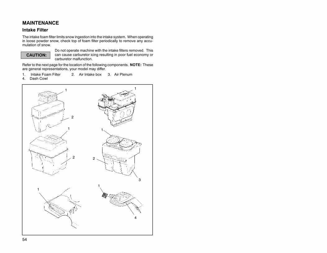
54
MAINTENANCEIntake FilterThe intake foam filter limits snow ingestion into the intake system. When operatingin loose powder snow, check top of foam filter periodically to remove any accu-mulation of snow.
Do not operate machine with the intake filters removed. Thiscan cause carburetor icing resulting in poor fuel economy orcarburetor malfunction.
Refer to the next page for the location of the following components. NOTE: Theseare general representations, your model may differ.
1. Intake Foam Filter 2. Air Intake box 3. Air Plenum4. Dash Cowl
CAUTION:
3
1
2
4
11
2 2
11
1

55
MAINTENANCE
Under Hood Air Intake System
The Indy 340s are equippedwith an under hood air intakesystem which should normallybe left open. The door shouldbe closed and latched above35°F (2°C) formaximumperfor-mance during warm weatheroperation. Simply pull the strapout and up to latch the door andreverse the procedure to openit.

56
MAINTENANCE
Spark Plug SelectionOriginal equipment parts or their equivalent should always be used. However, theheat range of spark plugs is of utmost importance. A spark plug with a heat rangewhich is too high will cause engine damage. A spark plug with a heat range whichis too low will cause excessive fouling and malfunction.
In selecting a spark plug heat range for production, a manufacturer is forced to as-sume that the engine is going to operated under extreme heavy duty conditions.This protects the engine from internal damage in the event that the purchaser actu-ally does operate the engine in this manner. This selection however, could causethe customerwho normally operates the engine undermediumor light duty to havespark plug failure. Refer to yourOwner’sManualSupplement for the specific sparkplug to be used in your machine.
CAUTION:
A plug with a heat range which is too high will always cause engine damage if theengine is operated in conditionsmore severe than that forwhich thespark plugwasintended.
A new engine can cause temporary spark plug fouling even though the heat rangeis proper, due to the preservative which has been added during assembly of theengine to combat rust and corrosion. Avoid prolonged idle speeds, as plug foulingand carbonization will result.
D Use recommended spark plugsD Proper electrode gap is .028″/0.7mmD Spark plug torque is 18-22 ft. lbs. (2.5-3 kg/m)D Always carry spare spark plugs in case of an emergencyNOTE: Incorrect fuelmixture can often cause a spark plug to appear to be too darkor too light in color. Before changing spark plug heat ranges, be sure the correctmain jet is installed in the carburetor(s).
The spark plug and its condition is indicative of engine operation. The spark plugfiring end condition should be read after the engine is warmed up and the vehicleis driven at higher speeds. Immediately check the spark plug for correct color.
NormalThe insulator tip is gray, tan, or light brown. There will be a few combustion depos-its. The electrodes are not burned or eroded. This indicates the proper type andheat range for the engine and the service.
NOTE: The tip should not be white. A white insulator tip indicates overheating,caused by use of an improper spark plug or incorrect carburetion adjustments.
Wet FouledThe insulator tip is black. A damp oily film covers the firing end. There may be acarbon layer over the entire nose. Generally, the electrodes are notworn. Generalcauses are excessive oil, use of non-recommended injection oil, excessive idling,idle too low or too rich, or weak ignition output.

57
MAINTENANCE
Spark Plug Removal and Replacement
WARNING
Never attempt to remove the spark plug whilethe engine is warm. The exhaust systemoren-gine could burn you, causing severe injury.
The spark plug is removed by using the specialwrench (1) provided in the tool kit. Remove thespark plug cap. Remove the spark plug by ro-tating counterclockwise.
Reverse the procedure for spark plug installa-tion. Torque to 18-22 ft. lbs. (2.5-3 kg/m).NOTE: Always check the gap on new sparkplugs with a wire gauge.
1

58
MAINTENANCE
Water Pump Belt Inspection
Some liquid cooled models willrequire an inspection of the wa-terpump belt. This belt inspec-tion interval is 1500 miles (2400km). Inspect beltwidth and con-dition as illustrated and replaceif cracking or worn past thewidth service limit (.250″ /6.35mm). If the belt needs to bereplaced, see your Polaris deal-er.
Replace if width is lessthan .25″ (6.35mm).Nominal new width is.345″ (8.75mm).

59
MAINTENANCEWater/Sediment Trap Service
Most Polaris snowmobiles incorporate patented carburetor bowl water/sedimenttraps which are located at the bottom of each carburetor. The trap consists of ahose with a plug, which should be inspected for contamination and drained at leastevery 2000 miles (3200 km).
WARNING
Whendraining the traps, fuel spillagewill occur. Be sure towork in a well ventilatedarea away from anything which may cause the fuel to ignite such as open flames,sparks, heaters, trouble lights, cigarettes, etc.
Cleaning Procedure - Plug1. Turn the fuel tank supply valve off.
2. Position a container or shop towelsto catch the contaminatedgasoline.
Heed the gasoline warningsfound on page 34.
3. Slide the clamp (1) away from thedrain plug (2) and remove the drainplug from the sediment tube.
4. Wipe off residue from plug andreinstall with clamps. Continueuntil all the traps have beenemptied.
Cleaning Procedure - Nipple1. Turn the fuel tank supply valve off.
2. Position a container or shop towelsto catch the contaminatedgasoline.
3. Slide the clamp (1) away from thenipple (3) and remove the nipple.Empty the tube and reinstall.Continue until all the traps havebeen emptied.
1
1
2
3

60
MAINTENANCE
Fuel Filter/Fuel Lines
CAUTION:
The fuel filter (3 - external fuel filter) (4 - in-tankfuel filter) and fuel lines should be inspectedregularly. Special attention should be given tothe system’s fuel line condition after periods ofstorage. Normal deterioration from weatherand fuel compounds can occur.
Oil Filter
The oil filter (5) is of a special design and mustnot be substituted. This filter should bechanged annually or every 1200 miles (1920km). Inspect oil line condition at 2000 miles(3200 km).NOTE: The direction of the arrows indicatesthe direction of the flow through the filters.
NOTE: After changing the oil filter, the oil injec-tion systemmust be bled of all trapped air. Seeyour dealer for instructions or have your dealerperform the filter change and bleeding opera-tion for you.
The only oil recommended for this system isPolaris brand oil.
3
5
4

61
MAINTENANCE
General Carburetor Information
The number size stamped in the end of the main jet indicates the jet size whichwasinstalled at the time of manufacture.
The installed main jet is not necessarily correct for your elevation.
It is the Polaris dealer’s responsibility to ensure that the correct main jets areinstalled in each machine for your area of operation.
WARNING
Carburetor adjustments should be performed only by a knowledgeable servicetechnician at a Polaris servicing dealer using the proper tools, procedures andspecifications.
Carburetor Adjustments
Proper carburetor adjustments include the following:D Carburetor component changes for specific altitude and ambient temperatures;D Choke adjustment and synchronization;D Air screw settings, if applicable;D Idle RPM adjustments;D Equalizing air flow at idle;D Equalizing air flow at off idle;D Throttle safety switch checks and servicing;D Throttle block to throttle flipper clearance adjustment; andD Oil pump lever and cable adjustment, where applicable.The frequency atwhich the carburetors are synchronized or balanced is important.Properly adjusted carburetors can greatly improve engine performance, fuel econ-omy, engine life and reliability.
Improperly adjusted or unsynchronized carburetors can lead to one ormore of thefollowing:D Hard starting.D Poor idle.D Overheated pistons and cylinder walls.D Plug fouling.D Poor engine response to various throttle valve openings.

62
MAINTENANCE
ACCS
3
1
22
1. Air Box
2. Vent Line Attachment
3. ACCS Valve
Somemodels are equippedwith thePolaris ACCS (Altitude CompensatingCarbu-retor System). The ACCS is designed to compensate automatically for changesin altitude without having to change carburetor jets. See your dealer for ACCSser-vice or adjustment.

63
MAINTENANCE
Carburetor Protection During Off Season Storage
Whenever the machine is stored for a period of more than 60 days it is highly rec-ommended that the engine be fogged with Polaris PN2870791. Follow the enginefogging instructions provided on the can. See pages 85-86 for more complete in-formation about storing your machine during the off season.
When preparing your snowmobile for off season storage we recommend that youadd a fuel conditioner/stabilizer or Premium Carbon Clean (2871326) to the fueltank. Follow the instructions on the can. Run the engine for five minutes to get ad-ditives through the entire fuel system. Then top off with fresh fuel.
If stabilizer is not used, the carburetors should be drained by removing the watertrap drain plugs. Catch fuel in a container or shop cloth. Reinstall plugs securely.Observe all fire safety rules when draining carburetors. See gasoline warnings onpage 34.
CAUTION:
Using lower than the recommended octane fuels or operating with obstructed fuelsystems will lead to costly engine damage.
Exhaust System
At approximately 2000 miles (3200 km) it is a good idea to check the exhaust sys-tem forwear or damage. To inspect, allow engine and exhaust system to cool com-pletely. Open the hood and inspect the muffler and pipes for cracks or damage.Check for weak or missing retaining springs or damper/support grommets.
WARNING
Exhaust system temperatures can exceed 900° F (500° C). Serious burns mayoccur if this inspection is performedwithout allowing adequate time for the exhaustsystem to cool. Never perform this procedure with the engine running.

64
MAINTENANCEEngine Cooling - Liquid Cooled ModelsThe cooling system on the liquid cooled Indy consists of the following major com-ponents: recovery tank, water pump, cylinders, heads, inlet and outlet manifolds,pressure cap and heat exchangers. The heat exchangers are located beneath therunning boards and front close-off panel in front of the drive shaft and/or under theseat. Coolant is pumped through the cylinders, heads, andmanifolds. The coolantis then pumped through the heat exchangers, where it is cooled as snow comesin contact with the fins on each exchanger. The “cooled down” fluid then returnsto the water pump and is re-circulated.Coolant MixtureThe coolant supplied in the system is a 50-50 mixture of ethylene-glycol and dis-tilled water. This mixture will provide protection against freezing at temperaturesdown to -34° F (-37° C). If greater protection against freezing is required, the per-centage of antifreeze to water may be increased. Use Premium 60/40 anti-freezecoolant. Never exceed a 60% antifreeze, 40% water mixture. Contact you dealerif greater protection is required.
NOTE: Never add tap water to the cooling system. Minerals cause deposits andmay react adversely with the metals in the engine and cooling system.Coolant High Temperature Indicator LightThe high temperature indicator light is controlled by a switch installed into the en-gine coolant system. If the engine coolant reaches a certain temperature, depend-ing on the model, the switch completes a circuit which turns the light on.
If you must drive themachine back to your starting point, drive slowly and stop fre-quently to allow normal cool down of the engine. Contact your dealer.Coolant LevelThe engine coolant level is controlled or maintained by the recovery system. Therecovery system components are: the coolant tank or overflow tank, engine fillerneck, pressure cap (in some models), and connecting hoses.
As coolant operating temperature increases, the expanding excess coolant isforced out of the engine, past the pressure cap (if applicable), and into the overflowtank. As engine coolant temperature decreases, this contracting coolant is drawnback up from the tank, past the pressure cap or filter and check valve, and backinto the engine.
CAUTION:
The coolant reservoir or surge tankmust bemaintained between theminimumandmaximum levels to prevent overheating and serious engine damage. Somemod-els, maintain coolant level at the “full cold” line on the coolant tank with the enginecold.Flushing the Cooling SystemTo ensure that the coolant maintains its ability to protect the engine, the systemshould be completely drained every two years and a fresh 50/50 or 60/40 mixtureof antifreeze and distilledwater should be added. This service must be donewhenthe engine is cold.

65
MAINTENANCE
Bleeding the Cooling System
WARNING
Never bleed the cooling system when the engineis hot. Severe personal injury could result fromsteam or hot liquid.Never remove the pressure cap (1) when the en-gine is warm or hot. If the pressure cap is to be re-moved, the engine must be cool.
Use of a non-standard pressure cap will not allowthe recovery system to function properly. If the capshould need replacement contact your dealer forthe correct replacement part and pressure rating.
Recovery System ModelsIf the coolant level becomes low in the recoverytank, the system should be bled of any trapped airusing the following procedure:
1. Fill the recovery tank with coolant to themaximum indicated mark.
2. Elevate front end of machine slightly to aidbleeding of the heat exchangers.
3. With pressure cap removed, add coolant andfill to the top of the filler neck.
4. Install the pressure cap with the lever lock upin its release position.
5. Run the engine at slow (600 RPM) for two to threeminutes. This will purge thesystem of trapped air.
6. Close the lever lock and check recovery tank fluid level.
CAUTION:
Most cooling systems are equipped with a filter (2) which should be periodically in-spected or replaced. If coolant flow becomes restricted or plugged, coolant loss,air lock or engine damage may result.
1
2

66
MAINTENANCE
Surge Tank Models1. Remove the pressure cap from the recovery tank and fill with properly mixed
coolant to the maximum indicated mark.
2. Elevate front end of machine slightly to aid bleeding of the heat exchangers.3. Remove the bleed screw from the water outlet manifold and/or the thermostat
housing. Allow the coolant to bleed through the system until it runs out thebleed holes. Reinstall the bleed screw into the manifold.
4. Fill the recovery tank back to the maximum indicated mark.
5. Start the engine and run at a fast idle for two to three minutes. Occasionallyloosen the bleed screw to purge any trapped air in the system.
6. Shut off engine and check the recovery tank level. Fill as required.
7. Feel the heat exchangers under the running boards. If the system is bledproperly, they will be warm to the touch. If they are not, repeat step four and liftthe front of the machine slightly to assist in the bleeding.
Throttle Cable Lubrication
With the engine off, lubricate thethrottle cable occasionally with Polar-is Cable Lubricant (PN 2870510).Turn the handlebars to the left and lu-bricate liberally as shown.
Choke and Cable Lubrication
Lubricate the choke slide and cablesoccasionally as shown with PolarisCable Lubricant (PN2870510). Oper-ate the choke intermittently beforeturning the machine off. This drawsmoisture out of the choke plungerarea and reduces the possibility of thechoke becoming frozen.

67
MAINTENANCE
Chaincase Oil LevelThe drive chain is continuously immersed in oil. Proper oil level is determined bychecking the level on the dipstick (C) with machine placed on a level surface. Theoil level should be between the “safe” marks on the dipstick. Add oil through dip-stick opening to maintain proper level. Use Polaris chaincase oil (PN 2871280).Do not overfill.
NOTE: Clean the magnetic plug (D) every 500 miles (800 km) and wheneverchecking or changing lubricant.
CAUTION:
Do notmix or use other types of lubricant. Excessive wear to chain, sprockets andbearings will result.
It is the owner’s responsibility to maintain proper lubrication of the chaincase.
Drive Chain TensionTo obtain correct chain tension:
1. Rotate driven clutchcounterclockwise to move allchain slack to the tensionerside. Lock the brake lever lockor have an assistant hold thebrake lever firmly.
2. Loosen the adjuster bolt jamnut (A).
3. Finger tighten the adjuster bolt(B) until it can no longer beadjusted by hand.
4. Back off the adjuster bolt by 1/4turn.
5. Tighten the jam nut whileholding the adjuster bolt.
6. The chain is now tensioned.Release the brake lever lock.
C
D
A
B

68
MAINTENANCE
Gearcase Oil Level (WideTrak Models)Using Polaris Chaincase Oil (PN2871281), maintain the proper oil lev-el. Proper oil level is determined bychecking the level on the dipstick (A)with machine placed on a level sur-face. The oil level should be betweenthe “safe” marks on the dipstick. Addoil through dipstick opening to main-tain proper level. Do not overfill.
NOTE: Clean the magnetic plug (B)every 500 miles (800 km) and when-ever checking or changing lubricant.
CAUTION:
Do not mix or use other types of lubri-cant. Excessive wear to chain,sprockets and bearings will result.
It is the owner’s responsibility to main-tain proper lubrication of the gearcase.
A
B

69
MAINTENANCE
Brake Inspection
The brake lever reserve shouldbe inspected frequently. Mea-sure the clearance between thelever and handlebar grip. In-spection should be made withthe lever firmly depressed. Le-ver reserve (A) should be noless than 1/2″ (1.3 cm).
Replacement of brake pads willbe necessary when the brakepad material is thinner than thebacking plate approximately(1/16″). A kit is available for re-placing brake pads. See yourdealer.
1. Brake Caliper2. Chaincase3. Brake Disc4. Backing Plate5. Brake Pad Materi-al (Replace whenthickness is less than1/16″.
Excessive Lever TravelThe snowmobile’s hydraulic brakes are self-adjusting. If excessive brake padclearance should develop, the machine should be returned to an authorizedPolar-is dealer for inspection and adjustment.
1
2
3
4
5
A

70
MAINTENANCE
Replenishing Brake Fluid
CAUTION:
Brake fluid is a hazardous material. Contact with decals, paint, and many plasticswill cause damage. Use proper precautions when handling brake fluid.Remove brake fluid master cylinder reservoir cover. Add Polaris brake fluid (PN2870990) as required to bring the level up to the top of the fluid level mark on theinside of the reservoir. The proper fluid level is 1/4-5/16″ (.6-.8 cm) below the lipof the reservoir opening on most models.NOTE: On some models, the brake fluid level can be seen through a plastic sightglass in the brake reservoir. If the fluid is sufficient, the sightglass will be black. Ifthe sight glass is any color other than black, you will need to add brake fluid.On all models, frequently check the reservoir to be sure it contains the correctamount of fluid.
Use only Polaris DOT 3 high temperature brake fluid (PN 2870990). Polaris brakefluid is sold in 12 oz. bottles.
WARNING
Do not over fill the master cylinder. Fluid expansion could cause brakes to lock,resulting in serious injury or death. Once a bottle of brake fluid is opened, usewhatis necessary and discard the rest. Do not store or use a partial bottle of brake fluid.Brake fluid is hygroscopic, meaning it rapidly absorbs moisture from the air. Thiscauses the boiling temperature of the brake fluid to drop, leading to early brakefade and the possibility of serious injury.
Dirt and debris should be kept off the master cylinder cover. The cover has ventslits to allow for diaphragmmovement. If these vents become plugged,movementof brake fluid below the diaphragm may be restricted, altering brake function.

71
MAINTENANCE
Bleeding the Hydraulic Brake SystemAir in the hydraulic brake systemwill cause a springy or spongy brake lever action.Bleeding is necessary to remove air from the system. Refer to illustration on page69.
1. Remove brake fluid master cylinder reservoir cover and gasket.
CAUTION:
Brake fluid is a hazardous material. Contact with decals, paint, and many plasticswill cause damage. Use proper precautions when handling brake fluid.
2. Fill the master cylinder reservoir (B) and replace gasket and cover. Keep thefluid level 1/4-5/16″ (.6-.8 cm) below lip of reservoir opening.
3. Fill the master cylinder reservoir (B) and replace gasket and cover. Keep thefluid level between the max and min marks on the side of the reservoir.
WARNING
Do not over fill the master cylinder. Fluid expansion could cause brakes to lock,resulting in serious injury or death.
4. Slip a rubber tube over the ball of the bleeder valve and direct the flow of fluidinto an approved container.
WARNING
Never re-use brake fluid. Brake fluid is hygroscopic, meaning it rapidly absorbsmoisture from the air. This causes the boiling temperature of the brake fluid todrop,leading to early brake fade and the possibility of serious injury.
5. Squeeze brake lever a full stroke. Then unscrew bleeder valve 3/4 of a turn torelease air.
6. Close bleeder valve and release brake lever.Repeat steps 4 and 5 until fluid flows from bleeder valve in a solid stream free ofair bubbles.7. Re-fill reservoir to proper level after bleeding operation. See Replenishing
Brake Fluid on page 70. Do not overfill the master cylinder.
8. Replace gasket and cover.During the bleeding procedure make sure to keep the brake handle in as level aposition as possible. The hydraulic fluid reservoir must be in this position to mini-mize the possibility of air entering the system through the reservoir vent.
WARNING
Excessive or repetitive use of brakes for high speed stops will cause an over-heated brake system. This overheated condition could cause sudden loss ofbrakes and/or fire, resulting in severe injury or death.
When traveling in long downhill stretches remember to use a pumping brake ac-tion. Riding the brakes can cause the brake system to overheat, resulting in brakefailure.

72
MAINTENANCE
Brake Adjustment - Mechanical Brakes
If excessive brake lever to brake block clearance is evident, the brake cable or cali-per should be adjusted using the following methods. When adjusting calipers, ad-just caliper adjuster bolt only. Do not adjust cable or cable sleeve length.
WARNING
Improper brake adjustment could result in brake failurewhich could result in severeinjury or death.
Cable Adjustment
1. Make sure floating parts movefreely and all parts are mountedsecurely. Tighten hardware asrequired.
2. Check actuator linkage to ensurethere is adequate freedom ofmovement for positive brakeoperation.
3. Loosen lock nuts (A).
4. To increase brake lever free play,turn nuts counterclockwise tomove cable (B) down in bracket.To decrease lever free play movecable up in bracket. Tighten locknuts.
5. If cable adjuster has reachedmaximum, the lever arm can bere-indexed twice beforebrakepads require replacement.When pads are replaced, brakelever arm must be re-indexed toobtain proper freeplay. Brakelever free play should be 1/4 - 3/8″(6-10 mm).
6. Loosen lock nuts and turn counterclockwise (as viewed from the top) to obtainthe maximum amount of cable freeplay. Straighten tab on tab washer andloosen bolt enough to disengage actuator lever spline.
A
B
1/4-3/8″ (6-10 mm)

73
MAINTENANCE
Cable Adjustment (Cont.)7. Slip long leg of lever spring (D) off
caliper and rotate to the side.8. Rotate lever (E) one tooth in the
direction opposite the actuationdirection and tighten bolt. Makesure spline teeth are properlyengaged.
9. Bend up a tab (C) aligning with oneof the bolt head flats to prevent boltrotation.
10. Return the spring to its originalposition on the caliper. Both leverand linkage must be free to returnto original position.
11. Perform steps 3. and 4. to adjust lever freeplay.12. Verify proper brake operation. Disc should rotate freely without drag.13. Check disc surface condition.
Mechanical Brakes
Brake Lever Travel
Measure the clearance between thelever and brake block. Inspectionshould be made with the lever firmlydepressed. Distance B should be nomore than 3/4″ (1.9 cm).
Excessive travel indicates a need toadjust the brake cable adjuster. Re-fer to the mechanical brake adjust-ment information on page 72.
E D
C
B

74
MAINTENANCE
Brake Inspection
WARNING
Be certain brake pads do not drag on disc and brake lever travel is not excessive.
Replacement of brake pads will be necessary when the brake padmaterial is thin-ner than the backing plate approximately (1/16″). A kit is available for replacingbrake pads. See your dealer.
1. Brake Caliper2. Chaincase3. Brake Disc4. Backing Plate5. Brake Pad Materi-
al (Replace whenthickness is lessthan 1/16″.
1
2
3
4
5

75
MAINTENANCEHeadlight AdjustmentThe headlight can be adjusted for verticalaim using the following procedure:1. Place snowmobile on a level surface
with headlight approximately 25’(7.6m) from a wall.
2. Measure distance from floor tocenter of headlight andmake amarkon the wall.
3. Start engine and turn headlightswitch to high beam.
4. Observe headlight aim. The mostintense part of the headlight beamshould be aimed 2″ (5.1 cm) belowthemark placed on thewall in Step 2.NOTE: Rider weight must beincluded on the seat.
5. On evolved models, turn theadjustment knob (B) located insidethe hood just below the headlampopening. Turn knob in or out asneeded for proper aim. Onaggressive models, insert a Phillipsscrewdriver into the access hole (C)on the top of the instrument housingand turning the screw until correctadjustment is achieved.
25’ (7.6 m)
Lamp CenterHeight
2″ (5.1 cm)
C
B
OR

76
MAINTENANCE
NOTE: Do not touch a halogen bulb with bare fingers. Oil from skin leaves a resi-due, causing a hot spot which will shorten the life of the lamp.
Removing Halogen Bulbs - Low Beam
1. Pinch ends of the spring (1) togetherand lift until it releases from the springretainer.
2. Lift spring carefully around wireharness (2) and flip to outside ofhousing.
3. With the wire harness attached to thebulb (3), withdraw bulb from housing.
4. Grasp bulb by metal base andcarefully separate bulb fromharness.
Installing the Bulb
1. Hold bulb by metal base and install into wire harness.
2. Insert bulb into housing.
3. Carefully flip spring back into housing placing it around wire harness.
4. Squeeze spring together until it is over the spring retainer and release.
5. Verify headlight aim.
Removing Halogen Bulbs - High Beam
1. Remove the wire harness
2. Gasp the bulb firmly and twist it 1/2turn counterclockwise.
NOTE: Do not touch a halogen bulb withbare fingers. Oil from skin leaves a resi-due, causing a hot spot which will shortenthe life of the lamp.
3. Remove the bulb from housing andreplace with new bulb.
4. Place the bulb and housing backinside the hole and turn the housing1/2 turn clockwise to lock into place.
5. Reinstall the wire harness to thehousing.
2
1
3

77
MAINTENANCE
NOTE: Do not touch a halogen bulb with bare fingers. Oil from skin leaves a resi-due, causing a hot spot which will shorten the life of the lamp.
Removing the Side Bulbs1. Disconnect terminal from back of bulb.
2. Turn bulb assembly 1/4 turn to right and withdraw from housing.
Installing the Side Bulbs
1. Hold bulb assembly by plastic base and plug into wire terminal.
2. Insert bulb assembly into housing.
3. Turn bulb assembly 1/4 turn to left to secure in housing.
4. Verify headlight operation.
Wrap Around Taillight Bulb Replacement
1. Remove Phillips screws fromtaillight lens (A).
2. Working from front to back,carefully pry lens away from sealand remove lens.
3. Pull bulb(s) (B) straight out fromsocket and insert new bulb.
4. Reinstall lens.B
A

78
MAINTENANCE
Handlebar Adjustment - All Other Models
Your snowmobile has handlebarswhichmay be adjusted for your person-al fit.
1. Remove handlebar cover andfoam.
2. Using a 7/16″ (11 mm) wrench,loosen four nuts on bottom ofadjuster block. NOTE: Turnhandlebar to left or right for accessto back nuts.
3. Adjust handlebar to the desired height. Be sure that handlebars, brake leverand throttle lever operate smoothly and do not hit the gas tank, windshield orany other part of the machine when turned fully to the left or right.
4. Torque the handlebar adjuster block bolts to 11-13 ft. lbs. (1.5-1.8 kg/m).
5. Replace handlebar cover and foam.
12
3
4

79
MAINTENANCE
Backrest AdjustmentThe passenger backrest on somemodels is adjustable. To move the backrest for-ward or backward, lift the adjustment lever on the left side (A).To lengthen or shorten the backrest cable, lift the cable until spring tension is feltand lock the jamb nut.When adjusting the backrest from a passenger position to a single rider position,rotate the backrest cushion adjustment knobs (B) until the proper angle is reached.The grab bars have five height adjustments. To raise or lower the grab bar, removethe grab bar adjuster knob (C), position the grab bar at the desired height, and rein-stall the knob.Some models are also equipped with passenger handwarmers. The switch (D),located under the left hand wind deflector, has three settings: High, Off, and Low.
B
D
C
A

80
MAINTENANCE
Drive Belt
WARNING
Periodically check the condition and tension of the drive belt. Always carry a sparebelt. Inspect clutch sheaves for damage, wear, or belt residue. Clean with non-oilbase cleaner such as isopropyl alcohol.To ensure satisfactory belt life, install belts so they operate in the same directionof rotation. Position the identification numbers so that you can read them. This willkeep the belt rotating in the same direction.For improved drive away during extreme cold temperatures, remove the belt andwarm it up to room temperature. Reinstall it before starting the vehicle.
Belt Removal - A
1. Be sure key switch is off andengine has come to a completestop. Remove the retainingknob or pin and open the clutchguard.
2. Apply brake (or lock parkingbrake if so equipped).
3. Grasp belt firmly midwaybetween clutches and pullupward and rearward. Removethe belt.
Belt Installation - B1. Drop the drive belt over the
drive clutch and pull back theslack. Numbers should bereadable from right side of unit.
2. Turn the driven clutchmoveable sheave clockwisewhile at the same time pushinginward and forcing the beltdown between the sheaves.
3. Hold the belt down between thesheaves and roll the bottomportion over the outer clutchsheave. Once installed, besureto work the belt to the outeredge of the sheave. Be sure torelease parking brake if applied.
4. Close the clutch guard andreinstall the retaining knob orpin.
B.1
B.3
A
A.3
B

81
MAINTENANCEClutch System
Donot lubricate clutch bushings. The bushings in theweights and rollers ofPolarisclutches are made of a material which may be damaged if lubricated. Clean clutchsheaves periodically to maintain optimum performance.
WARNING
All clutch maintenance and repairsmust be performed by an authorizedPolaris servicing dealer. Any unau-thorized modifications to clutches,such as adding or removing weightswill void the warranty.
If you become aware of higher thannormal engagement, an unusualvibration, or an unusual shift pattern,contact your dealer immediately. Donot operate the machine until correc-tions have been made.
Clutch Alignment and Offset
The primary drive belt is a very impor-tant part of the drive train. Proper ad-justment of the two clutches (torqueconverter assembly) is necessary toobtain proper belt life. The informa-tion on this page is most important inmaintaining proper tolerances. If youdesire more information, consult yourdealer.
The recommended offset between the drive and driven clutches with the belt re-moved is found on the Owner’s Manual Specification Supplement.
Clutch center distance and alignment are crucial in maintaining optimum perfor-mance. The drive belt is a very important part of the drive system. Belt to sheaveclearance in the drive clutch should be kept at a minimum. With a new belt, theleast amount of clearance will provide the best throttle response. See your dealerfor adjustments. Belt width and length must match the center distance of theclutches and sheave width of the drive clutch. For this reason, Polaris recom-mends that only O.E.M. belts be used. Other belts maymatch the dimensions, butcan drastically change the shift pattern, resulting in poor performance characteris-tics.
NOTE: A worn belt will continue to function, but will not deliver maximum perfor-mance. Always carry a spare belt in case of an emergency. Belt removal andinstallation are covered on page 80.
Clutch Alignment
See Owner’sManual Specifica-tion Supplement forspecification

82
MAINTENANCE
Clutch Center Distance
Measure belt deflection with bothclutches at rest and in their full neutralposition.
Place a straight edge on the belt andapply downward pressure while mea-suring at the point shown.
The recommended center distancefor your machine can be found on theOwner’s Manual Specification Sup-plement.
Due to tolerances in belt length, itmaybe necessary for your dealer to makeminor adjustments in the driven clutchto achieve correct belt tension.
Belt Deflection Adjustment (P-85 System)Adjustment can be done on P-85 clutches without removing the clutch from thejackshaft.
1. Pull belt into driven clutch to slightly open sheaves.
2. Loosen the three bolts on the adjustment cam.
3. To reduce distance between sheaves, turn cam counterclockwise. Torquebolts to 10 ft. lbs. (1.4 kg/m)
NOTE: If your model has a P-90 clutch, any adjustments must be performed byyour dealer.
Belt Tension
Straight EdgeMeasure atthis point

83
MAINTENANCE
Torque StopIf your machine is equipped with a torque stop, periodically check torque stopclearance. Before this procedure it will be necessary to ensure the clutches areproperly aligned. The torque stop clearance should be a minimum of .010″ to amaximum of .030″ from the engine case. Adjust if necessary and lock jam nut.
Reverse Kit MaintenanceIf your machine is equipped with reverse or if you have a reverse kit installed, it isespecially important to maintain track tension as specified on page 89.
WARNING
If specified track tension is notmaintained severe damage to themachinemay oc-cur, which can result in loss of vehicle control. Loss of control can result in severepersonal injury or death.D Never attempt to shift into reverse while machine is moving.D Allow engine to reach idle speed before attempting to shift into or out of reverse.
CAUTION:
If machine has not come to a complete stop before shifting, damage will occur tochaincase or transmission.
If you have had a reverse kit installed on your snowmobile, some maintenance willbe required. Follow these recommendations:
Chain TensionMaintain the proper chain tension. See page 67.
Oil LevelMaintain the oil level between the safe marks on the dipstick.
Oil Change
Change the oil annually.

84
MAINTENANCE
Reverse Operation
WARNING
This snowmobile is capable of excessive reverse speed! Reverse operation canbe dangerous even at moderate speeds. Steering control becomes difficult in re-verse. Misuse of reverse can result in serious injury or death.
The transmission may not always be in the gear indicated by the shift lever. Applythe throttle slowly until the correct gear is assured.
Make sure the shift lever is shifted completely into forward or reverse position. Donot force the shift lever into reverse if resistance is felt.
The gears may not always be aligned for shifting into reverse. Forcing the levermay cause the cable to bend. If resistance is felt, apply the throttle to move thegears to a different position and try to shift again.
Sometimes the drive belt will drag in the drive clutch causing slight tension in thetransmission,making it hard to shift. Shutting the engineoffwill remove this tensionand ease shifting. This should only happen during the break in of a new belt or ifthe drive/driven clutch center distance is too long. If this is the case, belt tensionadjustments should be made by your dealer.

85
MAINTENANCE
Extended StorageOff season or extended storage of your snowmobile requires you to take preventa-tive measures to aid against deterioration and to prolong the useful life of manycomponents.
Cleaning and Preservation of Hood, Chassis, and TrimProper storage starts by cleaning, washing, and waxing the hood, chassis, uphol-stery, and plastic parts. Clean and touch up with paint any rusted or bare metalsurfaces. Be sure that corrosive salt and acids are removed from surfaces beforebeginning preservation with waxes and rust inhibitors (grease, oil or paint).
The machine should be stored in a dry garage or shed out of direct sunlight andcovered with a fabric snowmobile cover. Plastic tarp can cause condensation toform and damage some snowmobile components.Controls and LinkageAll bushings, spindle shafts, and tie rod ends should be coated with a light coat ofoil or grease. Throttle controls and cables should be lubricated with Polaris cablelubricant (PN 2870510). Force a small amount of lubricant down the cable.BearingsTo prevent corrosion which will destroy the bearings, always grease jackshaft anddrive shaft clutch side bearings with a high quality bearing grease. See page 52.Electrical ConnectionsSeparate electrical connector blocks and clean corrosive build up from connec-tors. Lubricate or pack connector blocks with dielectric grease (PN 2871044) andre-connect. Replace worn or frayed electrical wire and connectors. Be surewiringharness is properly secured away from sharp edges, steering linkage, movingparts, and hot exhaust.Clutch and Drive SystemRemove drive belt and store in cool dry location. Lubricate sheave faces of driveand driven clutches with a light coat of oil orPolaris Cable Lubricant (PN2870510).Do not lubricate clutch components except driven clutch shaft bushing as outlinedin Snow Repair Manual.BatteryBattery must be prepared and maintained as outlined on page 45.Front SuspensionTo minimize fatigue on the front shocks and springs, it is recommended that thefront end of the machine be safely blocked off the ground, removing tension fromthe shocks and springs.

86
MAINTENANCEEngine and CarburetorProper off season preparation of the engine and fuel system is vital to the preven-tion of rust and corrosion formation on precision engine parts during storage.
Without proper storage, jet restriction can cause lean conditions and very poorslow speed driving quality.D When preparing your snowmobile for off-season storage we recommend that
you add fuel conditioner/stabilizer or Premium Carbon Clean ( PN 2871326) tothe fuel tank. Follow the instructions on the can. Run the engine for fiveminutesto get additives through the entire fuel system. Then top off the tank with freshfuel.
D Fog the engine with Polaris Fogging Oil (PN 2870791). This is available fromyour Polaris dealer. Follow the recommended procedures indicated on the can.
D If stabilizer is not used the carburetors should be drained by removing the thedrain plugs or nipples. Refer to page 59 for procedure. Catch fuel in a containeror shop cloth. Reinstall and tighten drain plugs securely. Observe all fire safetyrules when draining carburetors. See gasoline warning on page 34.
Engine and CarburetorUsing a fuel stabilizer and topping off the fuel tank eliminates the need to drain thefuel system. If you prefer to drain the fuel tank, use the following procedure:
1. Transfer unused fuel from the fuel tank to an approved fuel container using asiphon pump. Do not re-use fuel after storage.
2. Securely support the front of the snowmobile with a jack stand so the engine istilted rearward.
3. Remove the spark plug(s).4. Rotate the engine slowly,watching the piston until it is at BDC - lowest position
in the cylinder. On twin cylinder models the opposite piston will be up.5. Pour approximately two ounces of Polaris injector oil into the spark plug hole.
6. Wait one to two minutes and perform steps 4-6. on remaining cylinders.
7. Replace the spark plugs and set machine on floor
NOTE: This procedure is performed bestwhen the front of themachine is elevatedand the engine is tilted rearward.
Track and SuspensionUnder normal conditions moderatetrack tension should be maintainedduring summer storage. The rear ofthe machine should be supported offthe ground to allow free hanging of thetrack.
HINT: For easier starting after extended storage, add Polaris Premium 2 cycle lu-bricant to the fuel in the tank at a 40:1 ratio and run the engine for three to five min-utes before storage. This will lubricate the fuel pump diaphragm to keep it flexibleand help prevent loss of prime.

87
MAINTENANCE
Transporting the Snowmobile
Whenever the snowmobile is transported the followingmeasures should be taken:
1. Turn the fuel valve to “Off”.
2. Be certain the fuel cap and oil cap are installed correctly.
3. Always tie the snowmobile to the transporting unit securely using suitablestraps.

88
MAINTENANCE
Fall Tune UpTo obtain maximum performance and use from your snowmobile, we encourageyou to arrange for a fall service tune-up with your Polaris dealer. He has an experi-enced and trained service technician who is interested in keeping your machinein peak operating condition.
TowingIf a situation arises requiring the snowmobile to be towed by another snowmobile,attach the tow rope to the spindles, not the ski loops.
WARNING
Always remove the drive belt froma disabled snowmobile before towing to preventserious damage to the engine and drive system.
Tool KitTo help you performemergency and routinemaintenance, a tool kit is includedwithyour machine. Items included in the kit are:
D Tubular Socket
D Phillips Screwdriver
D Emergency Start Strap
D Tubular Socket Handle
DWrench
D Shielded screwdriver (only withmodels that have indy select orAFX shocks)
Remember, always keep toolswith the machine.
NOTE: Other tools are also neces-sary to perform maintenance work.They are called out throughout thismanual.
If necessary a replacement tool kitmay bepurchased fromyourPolaris dealer. Askfor PN 3083227.
For Your ProtectionFor your added protection it is a good idea to carry the following items with yoursnowmobile at all times:
S Spare Drive Belt S Extra Set of Spark PlugsS Tow Rope S Extra OilS Fuel Deicer S Winter Survival KitS Trail Map S Owner’s ManualS First Aid Kit

89
MAINTENANCE
Track Tension Data
Suspension(Refer to Specifi-cation Supple-ment for type)
Weight MeasurementLocation
Measurement
XTRA 12 121″ none 2″ behind railbumper
1/2″ (1.27 cm)free hanging
XTRA 12 133″ none 16″ ahead of rearidler shaft
1-1 1/8″ (2.54 -2.86 cm)
free hanging
XTRA 10 121″and 133″
10 lbs. (4.54 kg) 16″ ahead of rearidler shaft
3/8 - 1/2″ (1 - 1.3cm)
WideTrak Type 10 lbs. (4.54 kg) 16″ ahead of rearidler shaft
3/4 - 1″ (1.9 - 2.5cm)
XTRA Lite 121″,133″ and 136″
10 lbs. (4.54 kg) 16″ ahead of rearidler shaft
3/8 - 1/2″ (1 - 1.3cm)
XL 136″ 10 lbs. (4.54 kg) 16″ ahead of rearidler shaft
3/8 - 1/2″ (1 - 1.3cm)
WARNING
When performing the checks and adjustments recommended on the followingpages, stay clear of all moving parts to avoid serious personal injury. Do not per-form track measurement or adjustments with engine running.

90
MAINTENANCE
Track TensionTrack adjustment is critical for proper handling. Always maintain correct tensionand alignment.Tension adjustments should bemade only after the track iswarmed up and limber.
1. Turn the machine off.
2. Lift the rear of the machineand safely support it off theground.
3. Place the recommendedweight or downwardpressure on the track at thespecified distance (seechart) ahead of the center ofthe rear idler wheel.
NOTE: Measure at the pointwhere the weight is hanging.4. Check for specified slack
between the wear surface ofthe track clip and the plastichi-fax (C).
If the track needs adjustment:
5. Loosen rear idler shaft bolt(D).
6. Loosen locknuts (A) (except on models with Xtra Lite suspension).
7. Tighten or loosen the track adjusting screws (B) as necessary to provideequaladjustment on both sides of the track.
8. Repeat measurement on the other side of the track. NOTE: Check morefrequently when machine is new.
9. Start machine and slowly rotate the track at least five revolutions, let the trackstop rotating by itself (do not apply brakes).
10. Check track alignment (side to side) by comparing the distance from the guideclip to Hi-fax on both sides. Readjust until centered.
11. Tighten Locknuts (A)
12. Tighten Idler Shaft Bolt (D)
C
B A D
Track
Hi-faxXTRA 10
C B AD
WIDETRAK
weight
weight

91
MAINTENANCE
C
BD
10 lb. Weight(4.5 kg)
Track
Hi-fax
XTRA LITE
2″
121″ = 1/2″133″ = 1-1 1/8″measured 16″aheadof rear idler center
Rail bumper
Rearidlershaftbolt
Track
Hi-fax
Trackadjustingbolt
XTRA 12

92
MAINTENANCE
WARNING
When performing the following checks and adjustments, stay clear of all movingparts to avoid serious personal injury.
Track AlignmentA periodic check should be made to see that the track is centered and runningevenly on the slide rails. Misalignment will cause excessive wear to the track andslide rail. NOTE: If excessive hi-fax wear occurs due to poor snow conditions,additional wheel kits are available. Consult your dealer.
1. Safely support the rear of the machine with the track off the ground.
2. Start the engine and apply a small amount of throttle until the track turns slowlyat least five complete revolutions. Stop the engine.
3. Inspect track alignment bylooking through the trackwindow to make sure therails are evenly spaced oneach side. If the track runs tothe left, loosen left locknutand tighten the left adjustingbolt. If the track runs to theright, loosen right locknutand tighten the rightadjusting bolt.
4. After adjustments arecomplete, be sure to tightenlocknuts and idler shaftbolts. Torque to 35-40 ft. lbs.(4.8-5.5 kg/m).
5. Repeat step 2 to verifyproper alignment.
Looking throughtrack window,make sure therails are evenlyspaced on eachside.
Rail
Hi-fax
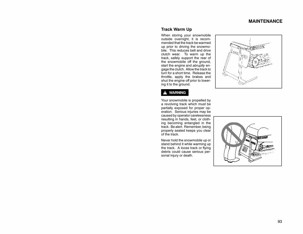
93
MAINTENANCE
Track Warm UpWhen storing your snowmobileoutside overnight, it is recom-mended that the track bewarmedup prior to driving the snowmo-bile. This reduces belt and driveclutch wear. To warm up thetrack, safely support the rear ofthe snowmobile off the ground,start the engine and abruptly en-gage the clutch. Allow the track toturn for a short time. Release thethrottle, apply the brakes andshut the engine off prior to lower-ing it to the ground.
WARNING
Your snowmobile is propelled bya revolving track which must bepartially exposed for proper op-eration. Serious injuries may becaused by operator carelessnessresulting in hands, feet, or cloth-ing becoming entangled in thetrack. Be alert. Remember, beingproperly seated keeps you clearof the track.
Never hold the snowmobile up orstand behind it while warming upthe track. A loose track or flyingdebris could cause serious per-sonal injury or death.
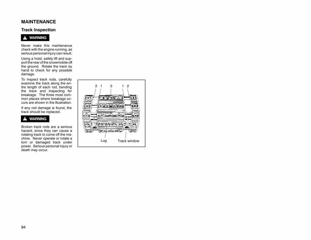
94
MAINTENANCE
Track Inspection
WARNING
Never make this maintenancecheck with the engine running, asserious personal injury can result.
Using a hoist, safely lift and sup-port the rear of the snowmobile offthe ground. Rotate the track byhand to check for any possibledamage.
To inspect track rods, carefullyexamine the track along the en-tire length of each rod, bendingthe track and inspecting forbreakage. The three most com-mon places where breakage oc-curs are shown in the illustration.
If any rod damage is found, thetrack should be replaced.
WARNING
Broken track rods are a serioushazard, since they can cause arotating track to come off the ma-chine. Never operate or rotate atorn or damaged track underpower. Serious personal injury ordeath may occur.
21312
Track windowLug

95
MAINTENANCETrack Lubrication
WARNING
Track failure, loss of vehicle control and braking ability can result from extendeduse of this vehicle on surfaces providing marginal lubrication between hi-fax andtrack guide clips. Examples of marginal lubrication would include lakes withoutsnow cover, icy trails and no-snow conditions.
The slide rail is designed to operate in conditions with adequate snow cover in or-der to provide sufficient lubrication. Excessive wear indicates insufficient lubrica-tion. New hi-fax can cause faster heat build up in limited lubrication than used hi-fax, resulting in excessive wear. NOTE: If excessive hi-fax wear occurs due topoor snow conditions, additional wheel kits are available. Consult your dealer.
CAUTION:
Track damage or failure caused by operation on ice or poor lubrication conditionswill void the track warranty.
Traction ProductsNOTE: Tracks with deep lug design cannot be studded.
CAUTION:
Polaris does not recommend the use of traction products on WideTrak snowmo-biles.
CAUTION:
If traction products are to be added to the track, wear strips must be installed in thetunnel to avoid excessive wear. This applies to all models.
Shims should never be added to the wear strip or track damage will result due tolack of clearance between upper carrier wheels and track.
Use of studs greater than 1″ (2.5 cm) on machines equipped with center coolerswill result in center cooler damage, or damage to tunnel.
Always inspect for track damage before using the vehicle. Use of traction productssuch as studs, ice growsers, paddles, etc.will increase the possibility of track dam-age and/or failure, which could cause loss of control resulting in severe injury ordeath.
In the event youwish to install studs, carbides or ice growsers, contact yourPolarisdealer for advice.
Track damage or failure resulting from improper or excessive stud installationvoids any track warranty, as does installation of the Hooker™ stud system.

96
MAINTENANCE
WARNING
Proper balance of traction products on the skis and track must be maintained toobtain proper vehicle control on hard packed snowor ice. Loss ofcontrol can resultin severe personal injury or death.
If yourmachine is equipped with carbide skags or you are adding them, it may alsobe necessary to add track studs in order to maintain proper vehicle control whileturning on hard packed snow or ice.
Track Studding
IMPORTANT: Before equipping your machine with traction products, be aware ofthe laws in your area pertaining to the use of traction products.
Track studding will enhance braking control on hard packed snow or ice, but ex-treme caution is still required on such surfaces. Use extra cautionwhen track stud-ding is employed as steering ability may be reduced on hard packed snow or ice.
The addition of carbide skags (if not already installed) is recommended withstudded tracks to aid in maintaining proper vehicle steering and control. Properbalance must be maintained between the number of studs and the length of car-bide on skags. As a rule of thumb, the more studs, the longer the carbide on theskags should be. Polaris offers carbide skags in 3″, 4″, 5″, 6″, 8″, 10″ (7.6, 10.2,12.7, 15.2, 20.3, 25.4 and 35.6 cm) lengths.
Inspect carbide skags and studs frequently. Worn studs or skags can reducesteering and braking control on hard packed snow and ice. Replace worn tractionproducts as required to maintain proper balance and vehicle control.
When studded tracks are used, increased wear to the brake pads will result fromincreased braking effort. Extended wear brake pad kits are available. See yourdealer for more information.
Tunnel wear strips must be installed whenever track studding is used in order toavoid excessive tunnel wear. Several wear strips are available. See your dealerfor the correct part for your machine.
See dealer track studding chart for recommended studding and skags.
CAUTION: Whenusing someaggressive studding patterns, itmay be nec-essary to grind protruding stud bolts flush to prevent idler wheel damage.
CAUTION: Track tension must be maintained on the tight side of specwhen studs are used to prevent front engine heat exchanger damage.
CAUTION: Center of stud must be at least 1 1/8″ (2.86 cm) from the edgeof the outer belt.

97
MAINTENANCE
Wear StripsMostmodels come from the fac-tory with tunnel wear strips orwear strip coolers installed.Check your specification sup-plement to see if yourmodel haswearstrips. These wear stripsare designed for a specific studlength. See your dealer’s stud-ding chart for recommendedtraction accessories.
CAUTION:
Use of studs greater than 1″ (2.5cm) onmachines equipped withcenter coolers will result in cen-ter cooler damage.
Whenever wear strips are relo-cated, check to be sure there isadequate stud clearance to theheat exchangers. Without prop-er clearance damage to heatexchangers will result.
Wear stripmountingholes
Top of Tunnel
Wear Strip
Track
View from rear of trackForward

98
MAINTENANCE
Steering System
The steering systems on Polaris snowmobiles have the following adjustments:D Ski toe or alignmentD Handlebar centeringD Spindle camberImproper adjustment of these components can cause erratic steering. Consultyour dealer if a need for adjustment should become necessary.
Steering Inspection and Adjustment
The steering assembly of themachine should be checked pe-riodically for loose nuts andbolts. See A,B,C,D,E,F and G inillustration at right.
With handlebars in straightahead position and measuringfrom the straight edge of theskis, the measurement betweenthe skis at point H should be 1/8to 1/4 inches greater than pointI. Refer to illustrations on page99 for component locations.NOTE: This measurementshould be taken with the vehicleweight compressing the sus-pension If the skis are misa-ligned, we recommend that yourdealer correct this, as the cam-ber adjustment may also be af-fected.
WARNING
Do not attempt to change the skialignment or camber adjust-ment. Contact your Polarisdealer. Improper alignment oradjustment may cause loss ofsteering control, resulting in se-rious injury or death.
F
D C
B
AG
E
CHECK FOR LOOSE FASTENERS
CRC Suspension With Rack Steering
F E D C
B
AG
All Steering Except CRC
G

99
MAINTENANCE
H
I
H
I
10″
10″
All other steering systems
10″
10″
CRC Suspension with Rack Steering

100
MAINTENANCE
Ski Skags
The skag is a replaceable barattached to the underside of theski. The purpose of the skag isto assist in turning the snowmo-bile and to prevent the wearingaway of the ski caused by con-tact with roads and other bareterrain. We recommend thatskags be checked once a weekto maintain positive steeringcharacteristics. Skags must bereplaced when worn to half theiroriginal diameter. NOTE: Seedealer track studding and skagchart for recommended skags.
WARNING
Worn skis and/or skags will ad-versely affect handling. Seeyour dealer’s studding chart forrecommended skags.
WARNING
If you install longer or more aggressive carbide skags than the original equipment,itmay also be necessary to add track studs in order to maintain proper vehicle con-trol while turning on hard packed snow or ice. Loss of vehicle control may causeserious injury or death.
Skag Replacement
1. Raise and support the front of the machine so the skis are approximately 6″(15.2 cm) from the ground.
2. Remove the attaching nuts and pry the skag downward.
3. Remove the forward portion of the skag.
Reverse this procedure for new skag installation.
CAUTION:
Avoid excessive tipping of the machine, causing the carburetor(s) to overflow fromtheir vent(s). Spilled fuel may cause damage to plastic or painted finishes.
Standard Skag
Easy Steer Skag
Steel Ski
Composite Ski
Skag
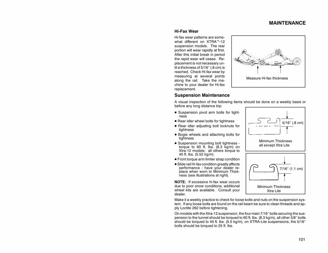
101
MAINTENANCE
Hi-Fax WearHi-fax wear patterns are some-what different on XTRA™-12suspension models. The rearportion will wear rapidly at first.After this initial break in periodthe rapid wear will cease. Re-placement is not necessary un-til a thickness of 5/16″ (.8 cm) isreached. Check Hi-fax wear bymeasuring at several pointsalong the rail. Take the ma-chine to your dealer for Hi-faxreplacement.
Suspension MaintenanceA visual inspection of the following items should be done on a weekly basis orbefore any long distance trip:
D Suspension pivot arm bolts for tight-ness
D Rear idler wheel bolts for tightnessD Rear idler adjusting bolt locknuts for
tightnessD Bogie wheels and attaching bolts for
tightnessD Suspension mounting bolt tightness -
torque to 60 ft. lbs. (8.3 kg/m) onXtra-12 models; all others torque to40 ft. lbs. (5.52 kg/m)
D Front torque arm limiter strap conditionDSlide rail Hi-fax condition greatly affects
performance - have your dealer re-place when worn to Minimum Thick-ness (see illustrations at right).
NOTE: If excessive hi-fax wear occursdue to poor snow conditions, additionalwheel kits are available. Consult yourdealer.
Make it a weekly practice to check for loose bolts and nuts on the suspension sys-tem. If any loose bolts are found on the rail beam be sure to clean threads and ap-ply Loctite 262 before tightening.
Onmodels with theXtra-12 suspension, the fourmain 7/16″bolts securing the sus-pension to the tunnel should be torqued to 60 ft. lbs. (8.3 kg/m), all other 3/8″ boltsshould be torqued to 40 ft. lbs. (5.5 kg/m), on XTRA-Lite suspensions, the 5/16″bolts should be torqued to 25 ft. lbs.
Measure Hi-fax thickness
5/16″ (.8 cm)
Minimum Thicknessall except Xtra Lite
7/16″ (1.1 cm)
Minimum ThicknessXtra Lite

102
MAINTENANCE
CAUTION:
If suspension bolts are re-moved, the threaded shaft mustbe cleaned thoroughly with abrake parts type cleaner. A newbolt, which must have a lockingpatch on the threads, must beinstalled. See your dealer forthe correct fastener for this ap-plication.
If rear idler wheel (1) assemblywashers are removed, be surethey are reinstalled with thedomed side of the washer fac-ing out (2) as shown.
21
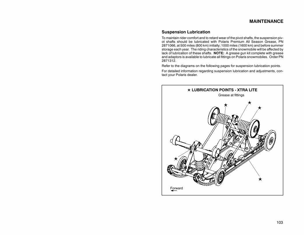
103
MAINTENANCE
Suspension LubricationTomaintain rider comfort and to retard wear of the pivot shafts, the suspension piv-ot shafts should be lubricated with Polaris Premium All Season Grease, PN2871066, at 500miles (800 km) initially; 1000miles (1600 km) and before summerstorage each year. The riding characteristics of the snowmobile will be affected bylack of lubrication of these shafts. NOTE: A grease gun kit complete with greaseand adaptors is available to lubricate all fittings on Polaris snowmobiles. OrderPN2871312.
Refer to the diagrams on the following pages for suspension lubrication points.
For detailed information regarding suspension lubrication and adjustments, con-tact your Polaris dealer.
L LUBRICATION POINTS - XTRA LITE
L
Grease at fittings
L
L
Forward
L
L

104
MAINTENANCE
Suspension Lubrication
NOTE: The following illustrations are general representations. Your model maydiffer. Lubrication points are indicated by a L and forward is to the left.
L
L
L
L
L
Forward
L
L
L
L
LL
Forward

105
MAINTENANCE
Suspension Lubrication
NOTE: The following illustrations are general representations. Your model maydiffer. Lubrication points are indicated by a L and forward is to the left.
L
LL
L
L
L
(Both sides)
Forward

106
SUSPENSION
Independent Front Suspension (IFS) Components
Refer to illustrations on following pages. NOTE: Illustrations are a general repre-sentation. Your model may differ.
1. IFS Compression Spring2. IFS Shock Absorber3. Trailing Arm4. Ski Spindle5. Ski Pivot6. Ski Stop7. Ski Pivot Bushing8. Lower Radius Rod9. Upper Radius Rod

107
SUSPENSION
Independent Front Suspension (IFS) Components
38
9
7 4
5
2
1
6
8
9
7
3
4
5
6
1
2

108
SUSPENSION
IFS Adjustment and Ski PressureIncreasing spring preload willincrease ski to ground pres-sure. Decreasing spring pre-load will decrease ski to groundpressure under all throttle posi-tions. NOTE: Increasing theIFS spring preload too far canadversely affect the handling ofthe snowmobile and rear sus-pension performance.
To adjust spring preload on theski, grasp the spring and turn ina clockwise direction (asviewed from the bottom of theshock) to increase the preload.Turn in a counterclockwisedirection to decrease preload.NOTE: Reducing the springpreload toomuchmay allow thespring retainer to fall off. Al-ways leave at least one threadshowing above the nut (A).
NOTE: In the adjacent illustra-tions, (B) indicates High Pre-load and (C) indicates low pre-load.
CAUTION: If the plastic nut isunscrewed from the threadedbody the nut will break. Alwaysleave one thread showingabove the plastic nut or thespring coils will stack, resultingin damage.
C
A
B
C
B

109
SUSPENSION
IFS Adjustment
Shock Absorber Components1. Retainer2. Shock Rod3. Jounce Bumper4. Body
When adjusting, be sure springs on both the left andright sides of the machine are at the same adjust-ment.
For the best ride the spring preload should be as low;as possible. Set the preload to use the full travel ofthe ski shockwith occasional light bottoming. To de-termine if your machine is using full travel, push theshock jounce bumper down as far as it will go on theshock rod and test ride the machine.
The bumper will move up on the rod in direct relationto the amount of travel. For example, if the shocktravel is full, the bumper will be seated at the top ofthe shock.
The purpose of the shock coil spring is to control rideheight. The purpose of shock valving is to controldamping. If you find that in order to obtain the desired ride effect the spring preloadis at itsmaximum, consider removing theexisting springand install the nexthighestrate spring.
D Remove the existing spring and install the next highest rate spring, orDReduce the preload on the existing spring and change the shock valving toobtain the desired effect.
WARNING
Changing shock valving on Foxt shocks requires special tools and a soundknowledge ofmechanical theory, tool use, and shopprocedures inorder toperformthe work safely and correctly. Shocks contain high pressure nitrogen gas. Ex-treme caution should be observed when handling and working with high pressureservice equipment. This work should be performed by a Polaris dealer.
Always verify ski alignment before making adjustments to the IFS. See page 98to check alignment. If the skis aremisaligned, we recommend that your dealer cor-rect this, as the camber adjustment may also be affected.
1
2
3
4

110
SUSPENSION
“Indy Select” IFS ShockSome snowmobiles are equipped with “Indy Select” IFS shocks, which allow thedriver to make adjustments to the compression valving of the front shocks by turn-ing adjustment screws (A) located near the base of the shocks.
By turning the screw clockwise, the compression of the shock increases, stiffeningthe ride. By turning counter clockwise, the compression decreases, softening theride. The factory setting is in the softest position. (Screw all the way out - counter-clockwise). If bottoming occurs, the “Select” feature should be used in conjunctionwith the spring preload to achieve the desired ride affect. One--half turn will affectthe ride considerably. There are approximately 3 turns of adjustment available.
A

111
SUSPENSION - XTRA 10
Refer to illustrations on following pages. NOTE: Illustrations are a general repre-sentation. Your model may differ.
1. Compression Valving Adjustment Screw2. Rear Limiter Strap3. RRSS (Rear Rear Scissor Stop)4. FRSS (Front Rear Scissor Stop)5. Limiter Strap (Adjustable)6. Limiter Strap (Quick Adjust)7. Rear Torsion Spring Adjuster(Cam - Low Position Shown)8. Front Limiter Strap9. Front Track Shock10. Torsion Spring11. Pivot Arm Shaft12 Rear Track Shock13. Carrier Wheel14. Coil Spring15. Rear Scissor16. Rail Tip17. Hi-fax18. Slide Rail19. Rail Bumper20. Bogie Wheel21. Rear Limiter Strap Adjuster22. Idler Wheel23. Front Torque Arm

112
SUSPENSIONRear Suspension Components - Xtra-10 Type
7
4 3
6
NOTE: General representation only.Your model may differ.
1
5
2
21
15

113
SUSPENSION
Rear Suspension Components - Xtra-10 Type
10
8
9
9
8
Forward
12
12
22
18
17
19
11
20
23
13
15
2
21
16
10
2019
14

114
SUSPENSION
Suspension Adjustment
The XTRA™ 10 suspension has been designed and set up to deliver a soft ride un-der average riding conditions. Rider weight, riding styles, trail conditions, and ve-hicle speed each affect suspension action.
The suspension can be adjusted to suit rider preference and deliver excellent per-formance for a given set of conditions. It should be noted, however, that suspen-sion adjustments involve a compromise or trade off. A machine set up to performwell in the moguls might not suit the preference of a groomed trail rider.
Adjustable Features and Adjustment Options
Independent Front Suspension (IFS)D Front shock spring preload
D Optional springsD Optional valving
Rear Suspension
D Torsion Spring PreloadD Front rear scissor stop (FRSS)D Rear rear scissor stop (RRSS)
D Optional coil springs for front track shockD Optional torsion springs
D Limiter straps - front and rearD Indy Select/Select AFX Rear Track Shock (if equipped)D Optional valving (Fox™ equipped models only)
Adjustment ProceduresIt is a good idea to break the suspension in for approximately 150 miles (240 km)and re-grease all suspension parts before fine tuning adjustments are made.
All settings will vary from rider to rider, depending on rider weight, vehicle speed,riding style, and trail conditions. We recommend starting with factory settings andthen customizing each adjustment individually to suit rider preference. The ma-chine should be methodically tested under the same conditions after each adjust-ment (trail and snow conditions, vehicle speed,riding position, etc.) until a satisfac-tory ride is achieved. Adjustments should be made to one area at a time, in orderto properly evaluate the change. DetailedDescriptions of suspensionadjustmentsare located further back in this owner’s manual.

115
SUSPENSION - XTRA 12
Refer to illustrations on following pages. NOTE: Illustrations are a general repre-sentation. Your model may differ.
1. Compression Valving Adjustment Screw2. RRSS (Rear Rear Scissor Stop)3. FRSS (Front Rear Scissor Stop)4. Limiter Strap (Adjustable)5. Rear Torsion Spring Adjuster(Cam - Low Position Shown)6. Front Track Shock7. Torsion Spring8 Rear Track Shock9. Carrier Wheel10. Rear Track Shock Coil Spring11. Rear Scissor12. Rail Tip13. Hi-fax14. Slide Rail15. Bogie Wheel16. Rail Bumper17. Front Track Spring18. Idler Wheel19. Front Torque Arm

116
SUSPENSION
Rear Suspension Components - Xtra-12 Type
3
2
17
5
1
10
4
6
11

117
SUSPENSION
Rear Suspension Components - Xtra-12 Type
4
6
64
Forward
8
8
18
14
13
16
4
10 10
19
9
*NOTE: General representation. Your model may differ.
12
32
7
15
7

118
SUSPENSION
Suspension Adjustment
The XTRA™ 12 suspension has been designed and set up to deliver a soft ride un-der average riding conditions. Rider weight, riding styles, trail conditions, and ve-hicle speed each affect suspension action.
The suspension can be adjusted to suit rider preference and deliver excellent per-formance for a given set of conditions. It should be noted, however, that suspen-sion adjustments involve a compromise or trade off. A machine set up to performwell in the moguls would not suit the preference of a groomed trail rider.
Adjustable Features and Adjustment Options
Independent Front Suspension (IFS)D Front shock spring preload
D Optional springsD Indy Select/Select AFX compression adjustment (if equipped)
Rear Suspension
D Spring preload - front track shockD Rear torsion spring preloadD Front rear scissor stop (FRSS)
D Optional coil springs for front track shockD Optional torsion springs
D Limiter strap - frontD Indy Select/Select AFX front and rear track shocks (if equipped)D Optional coil springs for rear track shock
Adjustment ProceduresIt is a good idea to break the suspension in for approximately 150 miles (240 km)and re-grease all suspension parts before fine tuning adjustments are made.
All settings will vary from rider to rider, depending on rider weight, vehicle speed,riding style, and trail conditions. We recommend starting with factory settings andthen customizing each adjustment individually to suit rider preference. The ma-chine should be methodically tested under the same conditions after each adjust-ment (trail and snow conditions, vehicle speed,riding position, etc.) until a satisfac-tory ride is achieved. Adjustments should be made to one area at a time, in orderto properly evaluate the change. detailed descriptions of suspension adjustmentsare located further back in this owner’s manual.

119
SUSPENSIONRear Suspension Components - Xtra Lite TypeRefer to illustrations on following pages. NOTE: Illustrations are a general repre-sentation. Your model may differ.
1. Front Track Shock2. Torsion Spring3 Rear Track Shock4. Carrier Wheel5. Rail Tip6. Hi-fax7. Slide Rail8. Bogie Wheel9. Rail Bumper10. Front Track Spring11. Idler Wheel12. Front Torque Arm13. Rear Torque Arm14. Rear Pivot Arm
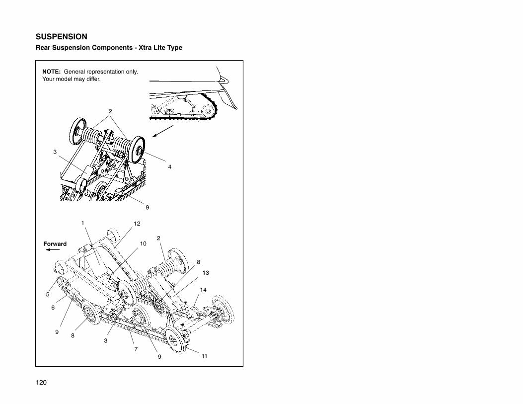
120
SUSPENSIONRear Suspension Components - Xtra Lite Type
9
3
NOTE: General representation only.Your model may differ.
2
Forward
117
6
9
8
12
8
1
13
145
4
102
93

121
SUSPENSIONRear Suspension Components - Wide Trak/Tran SportRefer to illustrations on following pages. NOTE: Illustrations are a general repre-sentation. Your model may differ.
1. Front Track Shock2. Torsion Spring3 Rear Track Spring4. Carrier Wheel5. Rail Tip6. Hi-fax7. Slide Rail8. Bogie Wheel9. Rail Bumper10. Front Track Spring11. Idler Wheel12. Front Torque Arm13. Adjuster Eyebolt14. Rear Shock15. Rear Torque Arm16. Rear Pivot Arm

122
SUSPENSION
Rear Suspension Components - Wide Trak
4
9
14
13
3
Forward
11
7
6
9
12
1
2
5
8
10
15
16
2
15
123
SUSPENSION
Suspension Adjustment
The Polaris WideTrak and Xtra Lite Type Suspensions have been designed andset up to deliver a soft ride under average riding conditions. Rider weight, ridingstyles, trail conditions, and vehicle speed each affect suspension action.
The suspension can be adjusted to suit rider preference and deliver excellent per-formance for a given set of conditions. It should be noted, however, that suspen-sion adjustments involve a compromise or trade off. A machine set up to performwell in the moguls would not suit the preference of a groomed trail rider.
Adjustable Features and Adjustment OptionsD Rear torsion spring preloadD Optional coil springs for front track shock
D Optional torsion springsD Front limiter strapD Optional coil springs for IFS shocks
Adjustment ProceduresIt is a good idea to break the suspension in for approximately 150 miles (240 km)and re-grease all suspension parts before fine tuning adjustments are made.
All settings will vary from rider to rider, depending on rider weight, vehicle speed,riding style, and trail conditions. We recommend starting with factory settings andthen customizing each adjustment individually to suit rider preference. The ma-chine should be methodically tested under the same conditions after each adjust-ment (trail and snow conditions, vehicle speed,riding position, etc.) until a satisfac-tory ride is achieved. Adjustments should be made to one area at a time, in orderto properly evaluate the change.

124
SUSPENSION“Indy Select” Rear ShockSome snowmobiles are equipped with the Indy Select/Select AFX rear shock,which allows the driver to make adjustments to the compression valving of the rearshock by turning the screw located near the base of the shock.
AdjustmentLocate the adjustment screw near the base of the shock. NOTE: This adjustmentis easiest to make with the machine tipped on its side using the special tool pro-vided in the tool kit that came with your machine.
WARNING
Be sure to shut off the fuelsupply before tipping themachine toprevent fuelspillageand flooding of the carburetors.
By turning the screw clockwise (a small screwdriver or dime work well), the com-pression valving is increased, stiffening the ride. To soften the ride, reduce thecompression by turning the screw counter-clockwise. A great deal of ride perfor-mance is accomplished with a mere 1/2 to 1 turns. There are approximately 3 fullturns of adjustment available.
How to AdjustUpon initial set-up, it is recommended that the suspension set up decal located onthe clutch guard or on the hood be followed. At this point, further adjustments forpersonal ride preference can be made.
If the suspension is “bottoming,” tighten the compression screw clockwise in 1/2turn increments until the bottoming stops. Backing off 1/4 turn counter-clockwiseat this point should give you the best possible ride ensuring use of the full travel ofthe suspension. The opposite procedure should be used if the suspension is toostiff upon initial set-up.
If bottoming continues after the screw is bottomed out (turned full clockwise), thetorsion spring should be adjusted with the adjustment block. See page 131. Backthe screw out to the original starting position after the torsion spring has been tight-ened.
Riding conditions are ever changing. Keep inmind the IndySelect can be adjustedat any time to achieve the best possible ride in any condition.
Position Sensitive ShockThere are no external adjustments on the position sensitive shock. Consult yourdealer of you desire to have the internal valving changed.

125
SUSPENSION
“Indy Select” Rear Shock
Turn spring clockwiseto increase preload
Turn screw clockwiseto tighten compression(stiffen)
Xtra-12 Type
AdjustmentScrew
Torsion SpringAdjustment Block(Low Setting Shown)
Xtra-10 Type

126
SUSPENSIONFront Torque Arm Limiter Strap Adjustment
One method of changing ski-to-snow pressure is to change thelength of the front torque armlimiter straps using the holesprovided. The limiter strap isnormally mounted in the fully ex-tended position. It is importantto note that decreasing limiterstrap length will stiffen the wholesuspension.
D Lengthening the straps de-creases ski pressure underacceleration.
D Shortening the straps in-creases ski pressure underacceleration.
The preferred method forchanging ski pressure understeady throttle condition is to in-crease or decrease IFS springpreload (only available on somemodels).
In addition, there are two posi-tions to mount the front trackshock. The upper position canbe used when reduced ski pres-sure is desired for ease of steer-ing or deep snow mobility.
Somemodels are equippedwithquick adjust front limiter straps.Adjustment is made by turningthe eyebolt nut to lengthen orshorten the straps. To shortenthe strap, turn the nut clockwise.To lengthen the strap, turn thenut counterclockwise.
If you need further assistancewith ride and handling, contactyour Polaris dealer.
Xtra-12Type
Lengthening the straps decreasesski pressure.
Shortening the straps increasesski pressure.
Upper front trackshock position.
Lower fronttrack shockposition.
Xtra-10 Type
Turn nut to adjust
Turning clockwise shortens strap.Turning counterclockwise lengthens strap.
Xtra-10Type

127
SUSPENSION
Suspension Set Up
A decal outlining rear suspension set up options is located either on the hood orthe clutch cover of your machine. These decals provide a guideline to be used forinitial suspension set up. Your set up may vary based on your desired riding style.
Xtra-12 Rear Suspension AdjustmentsThe primary rear suspension adjustments on Xtra-12models are the compressionvalving on both rear suspension shocks, the front track spring preload and the reartorsion spring preload. It is important to note that adjusting the limiter strap doesnot change weight transfer from the rear suspension to the skis as in a convention-al suspension. Instead it will increase the entire rear suspension preload and de-crease travel. To increase ski pressure the front rear scissor stop (FRSS) shouldbe set to low. To decrease ski pressure the FRSS should be set to high.
To properly adjust the rear suspension, start with the lightest preload setting thatwill prevent heavy bottoming. Adjustments should be made to one area at a time,in order to properly evaluate the change.
NOTE: Rear spring settings will affect ski-to-ground pressure. If ski pressure istoo light it may be desirable to tighten rear springs for an increase in ski-to-groundpressure. It is also possible to reposition the FRSS for increased ski pressure. Seepage 129.
Front Track Shock SpringFront track shock spring preload is adjusted by grasping the spring and turning ina clockwise direction to increase the preload. Turn in a counterclockwise directionto decrease preload.
Rear Track Shock SpringThe rear track shock coil spring does not have a threaded adjuster. One option todecrease preload for less aggressive riders is removal of the rear track shockspring.

128
SUSPENSION
Front Rear Scissor Stop (FRSS)The purpose of the front rear scissor stop (FRSS) is to control the bump attitudeof the rear suspension. As the front torque arm (FTA) hits the bump, it forces therear scissor to collapse a predetermined amount, depending on the FRSS blockposition.
This accomplishes two important things, it allows a lighter spring rate on the FTAbecause it can borrow spring rate from the rear torsion springs; and it prepares therear portion of the suspension for the bump.
The FRSS is made of a resilient material allowing smooth action and preventingany suspension component damage.
This unique feature is applied to the Xtra-10 and Xtra-12 rear suspensions. Pat-ents are pending.
Rear ScissorFront TorqueArm (FTA)
FRSS with short (low) leg to rear. Note the FTA goes down lowerbefore rear scissor begins to collapse.
Rear ScissorFront TorqueArm (FTA)
FRSS with long (high) leg to rear. Note this forces rear scissor tocollapse with less FTA movement than when in short position.
NOTE: General representation only. Your model may differ.

129
SUSPENSION
Front Rear Scissor Stop (FRSS)To adjust the FRSS compressthe rear portion of the rear sus-pension until the rear scissorpivots away from the FRSS.Turn adjuster to desired posi-tion. The dot on the stop indi-cates the high position. Highposition is with the dot locatedtoward the rear of the machine.(See illustration) Medium posi-tion is with the dot toward thefront of the machine. CAU-TION: Be sure both blocks arein the same position or suspen-sion damage may occur.NOTE: It may be necessary toloosen the FRSS mountingbolts to adjust the position. Re-tighten after adjustment.
If adjustment of the FRSS doesnot provide desired ski pres-sure, move the FRSS to the op-tional front hole. Remove the at-taching bolts and relocate theFRSS block in the forwardmosthole. Reinstall bolts and tight-en.
After moving the FRSS to theforwardmost hole, readjust theFRSS until desired ski pressureis obtained.
NOTE: The FRSS only controlsski pressure under steady statethrottle positions or decelera-tion. The RRSS controls skipressure under acceleration.
FRSS shown in high position,as indicated by dot on stop
ForwardRRSS
Rearscissor
Forward
Relocate FRSS toforwardmost holein rail for additionalski pressure
Block PositionMedium
High
LowLow

130
SUSPENSION
Xtra-12 Rear Rear Scissor Stop (RRSS)The RRSS on Xtra-12 type suspensions is not adjustable.
Xtra-10 Rear Rear Scissor Stop (RRSS)The RRSS controls weight transferfrom the skis to the rear suspension.It also influences the stiffness of theride by controlling the amount of cou-pling action between the front and reartorque arms. To increase the stiffnessof the Xtra-10 rear suspension, theRRSS should be set in the high posi-tion, but weight transfer will be re-duced under acceleration.
NOTE: On Xtra-10 models only theRRSScan be totally removed formax-imum weight transfer. However, un-less the torsion springs and rearshock valving are changed, the ridewill be compromised.
Also, tensioning the front limiter strapcan improve snow mobility in somesnow conditions. See your dealer formore information.
Whenmoving rear torque arm to lowermounting position (below tunnel), usedummy bolt in the hole where boltwasremoved to secure rear suspensionmounting pad. See your dealer formore information. (700 SKS only)
FRSS - low position shown
RRSS - lowpositionshown
FRSS - medium position shown
RRSS - highpositionshown
Stock mounting position.
Optional position - below tunnelbend line for heavy loads.
NOTE: Only available on 700 SKS

131
SUSPENSION
Torsion Spring Adjustment - Xtra-12 TypeTorsion spring preload is adjusted byturning the two position cam (A) onthe short leg of the spring as shownwith the engine spark plug tool. Thisadjustment is easier if the long springleg is lifted over the roller and re-placed after the cam is properly posi-tioned.
Torsion Spring Adjustment - Xtra-10 TypeRear spring tension adjustments are made by rotating the eccentric spring block(A) as shown with the engine spark plug tool. The block provides three springtension positions. This adjustment is easier if the long spring leg is lifted over theroller and replaced after the block is properly positioned.
Soft Tension Long End to Front
Firm Tension (Long End Up)
A
A
Soft Tension Long End to Front
Medium Tension (Short End Up) Firm Tension (Long End Up)
A
A
A
132
SUSPENSION
Suspension Performance Tips
Generally, rider weight determines the position at which the spring preload shouldbe set. However, this may varywith riding style. With a little experimentation, eachrider can find his or her best set-up. Remember, the adjustments are easy tomake,involve very little time or effort, and greatly affect the ride.
New hi-fax will offer improved performance over worn hi-fax in deep snow.
It is always a good idea to install a hood screen whenever operating in deep snow.This will help keep the underhood area clean of snow and debris, and will prohibitice build up.
Polaris offers track kits designed for improved flotation in deep snow. Your dealercan help you choose the correct kit for your machine.
When riding on ice or hard-packed snow, adding a set of bogie wheels to the railmay enhance the machine’s performance. Bogie wheel kits are available fromyour dealer.
IMPORTANT: Keep the suspension pivot points lubricated. This will reducemois-ture and rust build-up.

133
SUSPENSIONSUSPENSION COUPLING
On all Polaris snowmobile rear suspensions there are two torque arms that controlthemovement of the rail beam. Prior to theadvent of “SuspensionCoupling”, thesetorque arms could move independently of each other. Rear suspension “coupling”links the movement of the front and rear torque arms to each other, much like ananti-roll bar links the left hand and right hand front suspension skis to each other.There are two types of rear suspension coupling.
REAR TO FRONT COUPLING AND THE REAR REAR SCIS-SOR STOP (RRSS)
The Rear Rear scissor Stop (RRSS) couples the movement of the rear torque armto the front torque arm.
The RRSS limits the amount of independent movement between the rear torqueand the front torque arm.
When landing on the rear of the suspension, the rear torque armcompresses. TheRRSS links thatmovement to the front torque arm, causing it to compress, borrow-ing shock and spring damping from the front torque arm, reducing the possibilityof bottoming out.
FRONT TO REAR COUPLING AND THE FRONT REAR SCIS-SOR STOP (FRSS)
TheFrontRearScissorStop (FRSS) couples themovement of the front torque armto the rear torque arm.
The FRSS limits the amount of independence between the movement of the fronttorque arm tot he rear torque arm.
When hitting a bump, the front torque arm starts to compress. the FRSS links thatmovement to the rear torque arm, causing it to compress and raise the rear sus-pension up as one, only allowing the suspension to hit the bump once, eliminatingkickback.
TRADEOFFS
All suspension designs involve a compromise or tradeoff. For example, a suspen-sion set-up for snowcross racing applications would ride very stiff on the trail. Asuspension set-up for trail riding would bottom out harshly on a snowcross course.The same compromise holds true for the scissor stop locations.
FRONT REAR SCISSOR STOP (FRSS) - ATTRIBUTES
Moving the FRSS to a higher position or rearward hole will have the following af-fects on the suspension:D Slightly limit overall suspension travel.D Snow mobility will be slightly reduced.D Chatter bump ride will improve.D Bottoming out of the front torque arm will be reduced.D Secondary bump kick back will be reduced.

134
SUSPENSION
REAR REAR SCISSOR STOP (RRSS) - ATTRIBUTES
Moving theRRSS to a higher position or forward holewill have the following affectson the suspension:DWeight transfer will be reduced.D Chatter bump ride will improve.D Bottoming of the rear torque arm will be reduced.D Rear suspension action will become “stiffer.”

135
TROUBLESHOOTINGSuspension Troubleshooting -- Models with X-12
Problem Solution
Rear suspension bottoms too easily -Check to be sure FRSS block is in highestposition-Adjust torsion spring blocks to highest posi-tion-Adjust coil over spring on front track shock toincrease preload--Change torsion springs to .421 diameter (on121″ models only)-Change to next heavier coil springTurn indy select / AFX compression screwclockwise
Rides too stiff in rear -Check for binding suspension shafts andgrease all pivot points-Decrease spring preload adjustments-Remove rear track shock spring or reducerate of spring (refer to wallchart)-Change front track shock to lighter spring
--Change to lighter shock valving on modelsequipped with Indy Select shocks (refer towallchart)-Adjust front track shock spring to less pre-load.-Change FRSS to lowest position.
Machine darts from side to side -Make sure skis are aligned properly-Make sure spindles and all steering compo-nents are free turning-Make sure skags are straight on skis-Ensure use of “Easy-Steer” skags-Shift FRSS to highest position
Front end pushes -Check for worn skags-Check for binding suspension shafts andgrease all pivot points-Increase front IFS preload-Change FRSS to low setting or move to for-wardmost hole
Steering is heavy -Check ski alignment-Check skags and skis for damage-Change FRSS to high setting-Decrease IFS spring preload
Setting up for deep snow operation -Rotate FRSS to lowest setting, dependingupon rider preference-Decrease preload on front track spring-Move FRSS to forwardmost hole-Tighten limiter strap one hole

136
TROUBLESHOOTINGSuspension Troubleshooting -- Models with X-12, 133″
Problem Solution
Rear suspension bottoms too easily -Check to be sure FRSS block is in highestposition-Adjust torsion spring blocks to highest posi-tion-Adjust coil over spring on front track shock toincrease preload, replace front track springwith overload kit #2871439-Change to stiffer shock valving on Indy Selectfront track shock
Rides too stiff in rear -Check for binding suspension shafts andgrease all pivot points-Decrease spring preload adjustments-Remove rear track shock spring or reducerate of spring (refer to wallchart)-Change front track shock to lighter spring--Change to lighter shock valving on Indy Se-lect shocks
Machine darts from side to side -Make sure skis are aligned properly-Make sure spindles and all steering compo-nents are free turning-Make sure skags are straight on skis
Front end pushes -Check for worn skags-Check for binding suspension shafts andgrease all pivot points-Increase front IFS preload-Move FRSS to low position or move to for-ward hole
Steering is heavy -Check ski alignment-Check skags and skis for damage-Decrease IFS spring preload
Setting up for deep snow operation -Rotate FRSS to lowest setting, dependingupon rider preference-Decrease preload on front track spring-Tighten limiter strap one hole

137
TROUBLESHOOTING
Suspension Troubleshooting -- Models with X-10
Problem Solution
Rear suspension bottoms too easily -Increase torsion spring preload-Increase rear shock compression valving byturning screw clockwise (if equipped with op-tional Indy Select shock)--Change to heavier valving (if equipped withFox™ shocks)--Increase torsion spring wire diameter
Rides too stiff in rear -Check for binding suspension shafts andgrease all pivot points-Decrease torsion spring preload adjustments-Decrease rear shock compression valving byturning screw counterclockwise (if equippedwith optional Indy Select shock)-Change to lighter valving if (if equipped withFox™ shocks)-Check for proper track tension
Machine darts from side to side -Make sure skis are aligned properly-Make sure spindles and all steering compo-nents are free turning-Make sure skags are straight on skis-Check hi-fax and replace if worn-Reduce ski pressure:
DIncrease front track spring preloadDReduce IFS spring preload by adjustingcam or threaded adjusterDReduce rear torsion spring preload
Front end pushes -Check for worn skags-Check for binding suspension shafts andgrease all pivot points-Increase IFS spring preload by adjusting camor threaded adjuster-Decrease front limiter strap length
Steering is heavy -Check ski alignment-Check skags and skis for damage-Reduce ski pressure:
DIncrease front track spring preloadDReduce IFS spring preload by adjustingcamDReduce rear torsion spring preload
Setting up for deep snow operation -Change worn hi-fax-Move front track shock assembly to upperposition

138
TROUBLESHOOTING
Suspension Troubleshooting -- Models with X-10
Problem Probable Cause Solution
Harsh drive clutchengagement
Drive belt worn or toonarrow
Excessive belt/sheaveclearance
Replace.
CONTACT YOUR DEALER.
Drive belt turnsover
Wrong belt for applica-tion
Clutch alignment outof spec
Engine mount brokenor loose
Replace.
Adjust alignment offset.
Inspect/adjust or replace. CONTACT YOURDEALER.
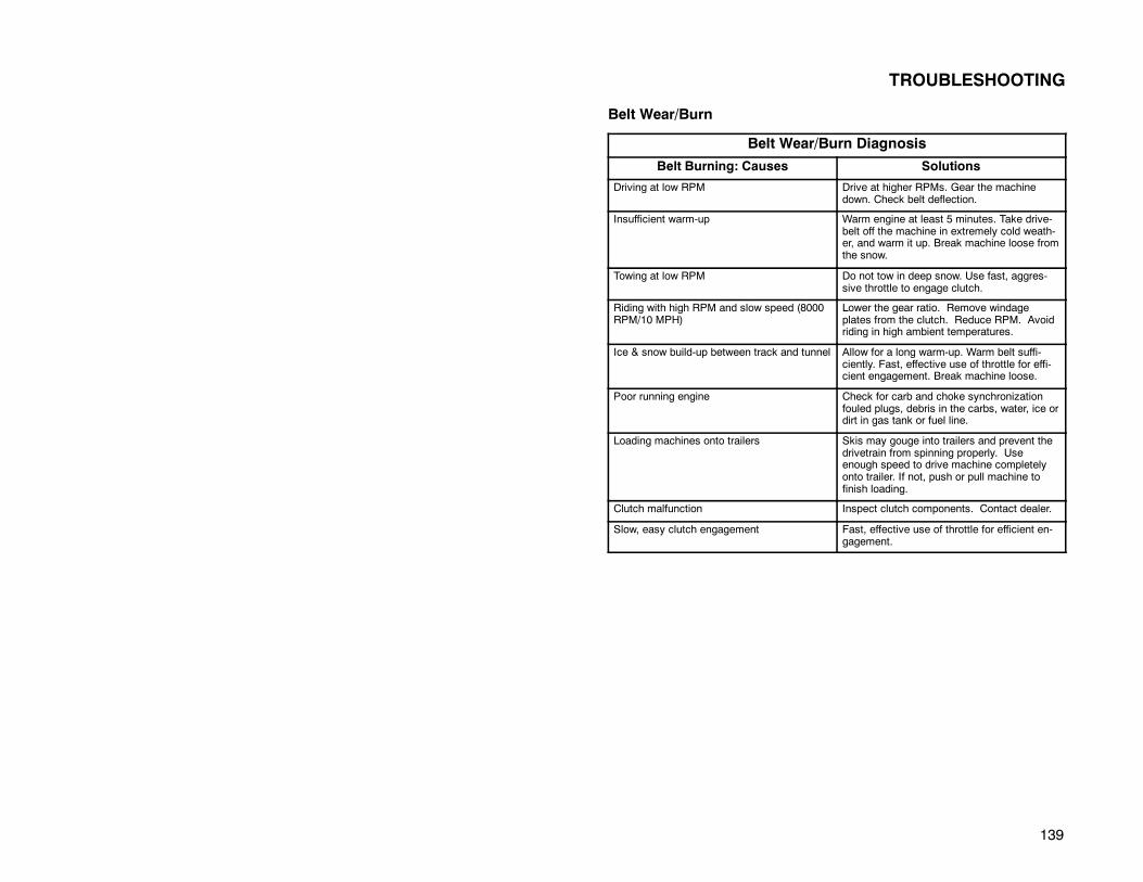
139
TROUBLESHOOTING
Belt Wear/Burn
Belt Wear/Burn Diagnosis
Belt Burning: Causes Solutions
Driving at low RPM Drive at higher RPMs. Gear the machinedown. Check belt deflection.
Insufficient warm-up Warm engine at least 5 minutes. Take drive-belt off the machine in extremely cold weath-er, and warm it up. Break machine loose fromthe snow.
Towing at low RPM Do not tow in deep snow. Use fast, aggres-sive throttle to engage clutch.
Riding with high RPM and slow speed (8000RPM/10 MPH)
Lower the gear ratio. Remove windageplates from the clutch. Reduce RPM. Avoidriding in high ambient temperatures.
Ice & snow build-up between track and tunnel Allow for a long warm-up. Warm belt suffi-ciently. Fast, effective use of throttle for effi-cient engagement. Break machine loose.
Poor running engine Check for carb and choke synchronizationfouled plugs, debris in the carbs, water, ice ordirt in gas tank or fuel line.
Loading machines onto trailers Skis may gouge into trailers and prevent thedrivetrain from spinning properly. Useenough speed to drive machine completelyonto trailer. If not, push or pull machine tofinish loading.
Clutch malfunction Inspect clutch components. Contact dealer.
Slow, easy clutch engagement Fast, effective use of throttle for efficient en-gagement.

140
TROUBLESHOOTING
Engine TroubleshootingCAUTION: Unless you have experience and training in two-cycle engine repair,see your dealer if technical problems arise.
Problem Probable Cause Solution
Erratic engine op-erating RPM duringacceleration orload variations
Drive clutch binding
Driven clutch malfunc-tion
a. Disassembly of drive clutch required to in-spect shift weights for wear and free opera-tion. CONTACT YOUR DEALER.
b. Clean and polish stationary shaft hub.
a. Replace ramp buttons. CONTACT YOURDEALER.
b. Inspect movable for excessive bushingclearance/replace. CONTACT YOUR DEAL-ER.
Machine fails tomove
Transmission in Neu-tralClutch jammed
Track jammed
Chaincase sprocket orchain jammed or bro-ken
Shift
Belt twisted, spring broken, weights stuck,lubricated, CONTACT YOUR DEALER.
a. Foreign object caught or hi-fax melted totrack clips due to lack of proper lubrication.
b. Machine may be frozen to ground. Trackmay be iced up.
Chain is loose or broken, chain tightener isloose. CONTACT YOUR DEALER.
Noise in drive sys-tem
Broken drive clutchcomponents
Bearing failure/ chain-case, jackshaft, orfront drive shaft
Drive belt surface flatspots
Drive chain loose orworn, sprocket teethbroken
CONTACT YOUR DEALER.
CONTACT YOUR DEALER.
Inspect/adjust or replace.
Inspect/replace.
Poor low RPM per-formance
Worn drive belt
Excessive belt/sheaveclearance
Loose torque stop
Sticky clutch
Inspect/replace.
CONTACT YOUR DEALER.
Inspect/adjust.
CONTACT YOUR DEALER.
Engine does notstart (electric startmodels)
Wire connections CONTACT YOUR DEALER.

141
TROUBLESHOOTING
Engine Troubleshooting
Problem Probable Cause Solution
Engine does notturn
Seized engine
Hydrostatic lock (fuelhas entered crank-case while vehiclewas standing or beingtransported)
CONTACT YOUR DEALER. Seizure is a re-sult of poor lubrication, inadequate fuel supply,broken parts, or improper cooling.
CONTACT YOUR DEALER to correct cause.Drain plug(s) located on lower crankcase foremergency draining.
Engine turns butfails to start
Faulty ignition
No fuel to engine
Flooded engine (nor-mal situation causedby too much choking)
Poor engine compres-sion
Remove spark plug(s) and replace with newplug(s). If engine still fails to start, check forspark; if no spark CONTACT YOUR DEALER.
a. Check tank level and fill up with correctfuel.
b. Ice in fuel line, filter, or pump. On the stan-dard Polaris carburetor, the choke will notfunction with the throttle depressed. See se-cond item under “Probable Cause” of “Enginecontinually backfires”.
Hold throttle open, crank engine several times(may be necessary to change plug(s), howev-er, the plug(s) may operate satisfactorily whendried).
Running too lean a mixture (too small a mainjet will cause seizure resulting in loss of pow-er). CONTACT YOUR DEALER. This indi-cates a major engine problem which must berepaired before engine is run.
Engine lackspower
Fouled or defectivespark plug
Fuel filter (loss of highRPM power)
Incorrect clutching
Carburetor and fuelpump
Change and test operation.
Check fuel filter flow. Disconnect hose anddrain about 1/2 cup. Fuel flow should besteady and encompass the entire diameter offuel line. If not, replace filter.
CONTACT YOUR DEALER.
There is no adjustment to change power out-put. CONTACT YOUR DEALER.
Engine continuallybackfires
Faulty plug(s)
Carburetor
Change plug(s)
Dirt or ice in fuel system. (Deicer should beadded to fuel at all times for assuranceagainst fuel line icing.
Engine requiresmore than normalpulls to start
Poor gasolineNot enough fuel get-ting to engine
Replace with “fresh” winter fuel.Refer to page NO TAG for primer instructions

142
ACCESSORIES
AccessoriesThere are a wide range of accessories available for Polaris snowmobiles. From Map Lightsto electric start, Polaris has the accessories that will make your ride even more pleasurable.Contact your dealer for a list of accessories available for your machine.
NOTE: Accessory tether switch available for all models - PN 2870668.
WARNING: Youmust only usePolaris parts and accessories on your 2000Polaris snowmo-bile. Use of non-Polaris approved parts and accessories may result in the following:
D Non-compliance with requirements
D Voiding warranty
D Personal injury to yourself or others
This applies but is not limited to the following areas: Brakes, clutches, fuel systems, andexhaust systems.
NOTE: Exhaust systems are critical safety areas and must use approved Polaris parts.Please see your Polaris dealer for service.
Maintenance ItemsBattery Tender 2871076. . . . . . . . . . . . . . . . . . . . . . . . . . . . . . . . . . . . . . . . . . . . . . . . . . . . . . . . .Gas Dock 2871254. . . . . . . . . . . . . . . . . . . . . . . . . . . . . . . . . . . . . . . . . . . . . . . . . . . . . . . . . . . .Nylon Starter Rope (100’ spool) 2870621. . . . . . . . . . . . . . . . . . . . . . . . . . . . . . . . . . . . . . . . . .Recoil Starter Handle 2870500. . . . . . . . . . . . . . . . . . . . . . . . . . . . . . . . . . . . . . . . . . . . . . . . . . .Fuel Filters (Pkg of 2) 2870622. . . . . . . . . . . . . . . . . . . . . . . . . . . . . . . . . . . . . . . . . . . . . . . . . . .Drive Belt Holders (Pkg of 2) 2870502. . . . . . . . . . . . . . . . . . . . . . . . . . . . . . . . . . . . . . . . . . . . .Tool Pouch 2870527. . . . . . . . . . . . . . . . . . . . . . . . . . . . . . . . . . . . . . . . . . . . . . . . . . . . . . . . . . . .Tool Kit 2870463. . . . . . . . . . . . . . . . . . . . . . . . . . . . . . . . . . . . . . . . . . . . . . . . . . . . . . . . . . . . . . .Carbon Clean 2871326. . . . . . . . . . . . . . . . . . . . . . . . . . . . . . . . . . . . . . . . . . . . . . . . . . . . . . . . .Pump for Chaincase Oil Gallon 2870465. . . . . . . . . . . . . . . . . . . . . . . . . . . . . . . . . . . . . . . . . . .Chaincase Oil - Gallon 2870464. . . . . . . . . . . . . . . . . . . . . . . . . . . . . . . . . . . . . . . . . . . . . . . . . .Chaincase Oil - 16 oz. 2871280. . . . . . . . . . . . . . . . . . . . . . . . . . . . . . . . . . . . . . . . . . . . . . . . . .Brake Fluid DOT 3, 12 oz. 2870990. . . . . . . . . . . . . . . . . . . . . . . . . . . . . . . . . . . . . . . . . . . . . . .Clutch Lube 4 oz. 2870510. . . . . . . . . . . . . . . . . . . . . . . . . . . . . . . . . . . . . . . . . . . . . . . . . . . . . .Grease, Premium All Season 2871066. . . . . . . . . . . . . . . . . . . . . . . . . . . . . . . . . . . . . . . . . . . .Anti-Corrosive Lubricant/Electrical Connector Lubricant 2871329. . . . . . . . . . . . . . . . . . . . . .Fuel Deicer, Isopropyl 2870505. . . . . . . . . . . . . . . . . . . . . . . . . . . . . . . . . . . . . . . . . . . . . . . . . .Fuel Stabilizer, 16 oz. 2870652. . . . . . . . . . . . . . . . . . . . . . . . . . . . . . . . . . . . . . . . . . . . . . . . . . .Fogging Oil 2870791. . . . . . . . . . . . . . . . . . . . . . . . . . . . . . . . . . . . . . . . . . . . . . . . . . . . . . . . . . .T-9 Metal Protectant 2871064. . . . . . . . . . . . . . . . . . . . . . . . . . . . . . . . . . . . . . . . . . . . . . . . . . . .Metal Polish 2870632. . . . . . . . . . . . . . . . . . . . . . . . . . . . . . . . . . . . . . . . . . . . . . . . . . . . . . . . . . .Grease Gun Kit (All Season) 3 oz. 2871312. . . . . . . . . . . . . . . . . . . . . . . . . . . . . . . . . . . . . . . .Refill Grease Cartridge (All Season) 3 oz. 2871322. . . . . . . . . . . . . . . . . . . . . . . . . . . . . . . . . .
Paint CodesPaint codes are found in your Owner’s Manual Supplement. Paints can be ordered direct fromMidwest Industrial Coatings (612-934-8252). Mix as directed.

143
SERVICE AND WARRANTY INFORMATION
Polaris Anti-Theft System
ThePolaris anti-theft systemmonitoring program (PATS) is designed to aid ownersof registered snowmobiles in recovery of their machines, if stolen.
Administration1. Polaris snowmobile owner reports theft.
A. In addition to notifying the proper law enforcement officials, theownermust call the Polaris warranty department in the UnitedStatesand Canada.
US #612-542-0500Canada #204-925-7100
B. Owners must provide their name, address, telephone number andmodel and serial number of stolen machines.
2. Polaris warranty will provide all dealerships with a monthly updated list of allstolen units, to further monitor thefts.
3. Polaris warranty will aid in notification of recovered units to their proper owner.
Obtaining Service and Warranty Assistance
Read carefully and understand the service data and the Polaris Warranty con-tained in this manual. Contact your Polaris dealer in matters pertaining to replace-ment parts, service orwarranty. He is constantly kept up to date on changes,modi-fications and tips on snowmobile maintenance, which may supersede informationcontained in this manual. He is familiar with our policies and procedures and willbe happy to assist you.
When writing about parts, service or warranty, always include the following in-formation:
1. Serial number 5. Details of trouble experienced
2. Model number 6. Length of time and conditions of operation
3. Dealer name 7. Indicate previous correspondence
4. Date of purchase
Use the following space to record the model and serial numbers of your machineand engine.
Machine Model No.
Machine Serial No.
Engine Model No.
Engine Serial No.

144
WARRANTYLIMITED WARRANTYPolaris Industries Inc., 1225 Highway 169 North, Minneapolis, Minnesota55441-5078, gives a ONE YEAR LIMITEDWARRANTY on all components of thePolaris snowmobile against defects in material or workmanship. This warrantycovers the parts and labor charges for repair or replacement of defective partswhich are covered by this warranty. This warranty begins on the date of purchase.This warranty is transferrable to another consumer during the warranty periodthrough a Polaris dealer. There is a charge of $35.00 payable to Polaris IndustriesInc.
REGISTRATIONAt the time of sale, the Warranty Registration Form must be completed by yourdealer and submitted to Polaris within ten days. Upon receipt of this registration,Polaris will record the registration for warranty. No verification of registration willbe sent to the purchaser as the copy of the Warranty Registration Form will be thewarranty entitlement. If you have not signed the original registration and receivedthe “customer copy”, please contact your dealer immediately. NO WARRANTYCOVERAGE WILL BE ALLOWED UNLESS YOUR SNOWMOBILE IS REG-ISTERED WITH POLARIS.
Initial dealer preparation and set-up of your snowmobile is very important in ensur-ing trouble-free operation. Purchasing a machine in the crate or without properdealer set-up will void your warranty coverage.
WARRANTY COVERAGE AND EXCLUSIONS:LIMITATIONS OF WARRANTIES AND REMEDIESThe warranty excludes any failures that are not caused by a defect in material orworkmanship. This warranty does not cover accidental damage, normal wear andtear, abuse or improper handling. This warranty also does not cover any snowmo-bile that has been altered structurally, neglected, improperly maintained, used forracing, or used for purposes other than for which it was manufactured, or for anydamages which occur during trailer transit or as a result of unauthorized serviceor the use of unauthorized parts. In addition, this warranty does not cover physicaldamage to paint or finish, stress cracks, tearing or puncturing of upholsterymateri-al, corrosion, or defects in parts, components or snowmobile due to fire, explosionsor any other cause beyond Polaris’ control.
This warranty does not cover the use of unauthorized lubricants, chemicals, orfuels that are not compatible with the snowmobile.
The exclusive remedy for breach of this warranty shall be, at Polaris’ exclusive op-tion, repair or replacement of any defective materials, or components or products.THEREMEDIES SET FORTH IN THISWARRANTYARETHEONLYREMEDIESAVAILABLE TO ANY PERSON FOR BREACH OF THISWARRANTY. POLARISSHALL HAVE NO LIABILITY TO ANY PERSON FOR INCIDENTAL, CONSE-QUENTIALORSPECIALDAMAGESOFANYDESCRIPTION,WHETHERARIS-ING OUT OF EXPRESS OR IMPLIED WARRANTY OR ANY OTHER CON-TRACT,NEGLIGENCE,OROTHERTORTOROTHERWISE. Somestates donotpermit the exclusion or limitation of incidental or consequential damages or impliedwarranties, so the above limitations or exclusions may not apply to you if inconsis-tent with controlling state law.

145
WARRANTY
ALL IMPLIEDWARRANTIES (INCLUDINGBUTNOT LIMITED TOTHE IMPLIEDWARRANTIES OF MERCHANTABILITY AND FITNESS FOR A PARTICULARPURPOSE)ARELIMITED INDURATIONTOTHEABOVEONEYEARWARRAN-TY PERIOD. POLARIS FURTHER DISCLAIMS ALL EXPRESS WARRANTIESNOT STATED IN THISWARRANTY. Some states do not allow limitations on howlong an impliedwarranty lasts, so the above limitationmay not apply to you if incon-sistent with controlling state law.
HOW TO OBTAIN WARRANTY SERVICEIf your snowmobile requires warranty service, you must take it to a Polaris dealerauthorized to repair Polaris snowmobiles. When requesting warranty service youmust present your copy of the Warranty Registration form to the dealer. (THECOST OF TRANSPORTATION TO AND FROM THE DEALER IS YOUR RE-SPONSIBILITY). Polaris suggests that you use your original selling dealer; how-ever, you may use any Polaris Servicing Dealer to perform warranty service.
Please work with your dealer to resolve any warranty issues. Should your dealerrequire any additional assistance they will contact the appropriate person atPolar-is.
This warranty also gives you specific legal rights, and you may also have otherrights which vary from state to state.
If any of the above terms are void because of state or federal law, all otherwarrantyterms will remain in effect.
Engine Oil
1. Always use Polaris engine oil.
2. Never substitute ormix oil brands as serious engine damage and voiding ofwar-ranty can result.

146
WARRANTY
Polaris Extended Service Contract
Polaris now is offering an extended engine service contract which provides the fol-lowing benefits:D Additional engine protection beyond the original twelve month warranty.D Backed by the strength of Polaris - no third party involvement.D Repairs use only genuine top quality Polaris parts.D Peace of mind. The Polaris Extended Service Contract is honored by all autho-
rized Polaris snowmobile dealers in North America. However, where possiblewe urge you to contact the selling dealer. There are no cards for you to carryas repair authorization for your dealer is only a phone call away.
DBecause the extended service contract is transferable for a $35.00 fee, thesnow-mobile’s resale value is increased.
D The Polaris Extended Service Contract is very affordable and can be financedwith the Polaris Star Card.
Conditions:
D The Polaris Extended Service Contract must be purchased within 90 days fromthe date of the unit’s registration.
D Each repair visit it subject to a $50.00 deductible.D The Extended Service Contract applies to the first 5000 miles or two calendar
years from date of registration, whichever comes first. Tampering with theodometer shall void the ExtendedService Contract. No extensions to coverageunder the Extended Service Contract will be given.
D Snowmobiles used in commercial purposes or for racing are excluded from cov-erage.
Coverage:
Second year coverage is extended to 1997 and 1998 model engine failures dueto defects in material and workmanship as determined by Polaris in its sole discre-tion. Used snowmobiles are not eligible under this program. A partial list of itemsexcluded from coverage includes:D Damage due to accident, fire, explosion, theft, or other causes beyond Polaris’
control.D Damage caused by the failure of other components of the snowmobile.D Failures caused by improper fuel or oil.D Failures caused due to improper adjustments, including but not limited to carbu-
retor jetting and clutching.D Failure due to unauthorized service.D Failures due to lack of service as required in the Owner’s Manual or Polaris up-
dates. This includes off season storage as listed in the Owner’s Manual.D Failure due to unauthorized parts or modifications.D Normal wear parts, including but not limited to: spark plugs, hoses, batteries,
controls, and recoil ropes are excluded from coverage. Gaskets are coveredas are intake and exhaust manifolds excluding paint coverage.
DElectrical coverage is limited to the CD and ECU box, coils, stator plate, and sen-sors. Wiring and other electrical components are excluded from coverage.

147
WARRANTY
Polaris Extended Service Contract
Coverage, Cont.:
DOil injection systemcoverage is limited to the controlmodule, sensors,solenoids,pump, and throttle cable switch.
D Cooling system coverage is limited to the water pump assembly and compo-nents, fan, fan bearings, temperature sensor, gasket and seals.
D Non-wear related carburetor parts are covered. Carburetor jetting and adjust-ments are excluded from coverage. The fuel pump and choke are covered.
D Clutches and related clutch parts, including but not limited to, the drive belt areexcluded from coverage.
D Electrical components are excluded from coverage.D The gearcase and transmission are excluded from coverage.
Polaris acknowledges the following products mentioned in this manual:Loctite, Registered Trademark of the Loctite CorporationSTA-BIL, Registered Trademark of Gold EagleFOX, Registered Trademark of Fox ShoxHi-Fax, Trademark of Himont Advanced MaterialsHooker Stud, Registered Trademark of Woody’s International Engineering and
Manufacturing, Inc.

INDEX
148
Accessories
142......................
AirIntake
System
54-55...............
Auxilliary
ShutO
ff29
..................Auxiliary
ShutO
ffSwitch
40............
BackrestA
djustment
79...............
Battery
45-47........................
Battery
Connections
45................
Battery
Fluid
45......................
Battery
Installation47
.................Battery
Rem
oval46
...................BeltD
eflectionAdjustm
ent82
...........Belt/W
earBurn
139...................
Bleeding
Cooling
System
65-66.........
Bleeding
theCooling
System
,RXLTouring
65-66...............
Brake
Adjustm
ent72-73
...............Brake
Bleeding
71....................
Brake
Fluid
Replenishm
ent70
..........Brake
Inspection69,74
................Brake
LeverTravel
13,69,73...........
Carburetor
Adjustm
ents61-62
..........Carburetor
Protection
63...............
Chaincase
OilLevel
67-68.............
Choke
andCable
Lubrication66
........Clutch
Alignm
entandOffset
81.........
Clutch
Center
Distance
82.............
Clutch
System
81.....................
Controls
andInstrum
ents,500
EFIS
KS
29..................
Coolant
64..........................
CoolantLevel
64.....................
Cooling
System
,Bleeding
65-66........
Daily
Storage
44......................
Drive
BeltInstallation
80...............
Drive
BeltR
emoval
80.................
Drive
Chain
Tension67
................Drive
System
31......................
Emergency
Starting
42................
Emergency
Stopping
Procedure
42......
Engine
Break
In37
...................Engine
Cooling
64....................
Engine
ShutO
ffSwitch
29.............
Engine
Troubleshooting140-141
........ExhaustS
ystem63
...................Extended
Storage
85..................
Flushing
theCooling
System
64.........
FrontR
earScissor
Stop
(FRSS)
129....
FrontTrack
Shock
Spring
127..........
FuelS
ystemDeicers
36...............
Greasing
Couplers
53.................
Greasing
DriveshaftB
earing53
.........Greasing
JackshaftBearing
53.........
Handlebar
Adjustm
ent78
..............HeadlightA
djustment
75...............
HeadlightB
ulbInstallation
76...........
HeadlightB
ulbRem
oval76
.............Hi-Fax
Wear
101.....................
High
Temperature
IndicatorLight
64.....
Identificationand
Specifications
26-30...
IFSAdjustm
ent108-109
...............Indy
SelectS
hock,110124-125
........Installing
theSide
Bulbs
77.............
Limiter
Strap
Adjustm
ent126
...........Low
OilIndicator
Light32
..............Lubricant,P
remium
2-Cycle
32.........
Lubrication52
........................Maintenance
48-105..................
Maintenance
Check,W
eekly48
.........Maintenance
Inspection,150Mile
49-51..
Maintenance
Inspection,1000Mile
49-51.
Maintenance
Inspection,2000Mile
49-51.
OilF
ilter60
..........................OilInjection
System
32................
Operation
31-44......................
Operation
Warnings
10-24.............
Owner
Maintenance
Program
48........
Oxygenated
Fuels
35.................
PaintC
odes142
......................Park
Brake
14.......................
Pre-R
ideWarm
Up
43.................
Pre-S
tartCheck
38...................
Preservation
oftheEnvironm
ent25
......Rear
Rear
Scissor
Stop
(RRSS)
130.....
Rear
Suspension
Adjustm
ents127
......Rear
Suspension,W
T,TranSport
121-122Rear
Suspension,X
10112-113
.........Rear
Suspension,X
12116-117
.........Rear
Suspension,X
-Lite119-120
.......Rear
TorsionSpring
131...............
Rear
TrackShock
Spring
127...........
Rem
ovingthe
Side
Bulbs
77............
Reserve
Capacity
36..................
Reverse
KitM
aintenance83
............Reverse
Operation
84.................
Safety
Alert
1-2......................
Safety
Warning
andOperation
Decals
2-9Scissor
Stop
128-130.................
Sedim
entTrapService
59..............
Service
andWarranty
Information
143....
Skag
Replacem
ent100
................SkiS
kags100
.......................Spark
Plug
Rem
oval57
................Spark
Plug
Selection
56...............
Spring
Tension,Rear
131..............
Starting
aCold
Engine
38..............
Starting
aWarm
Engine
39.............
Steering
Inspectionand
Adjustm
ent98
...Steering
System
98...................
Storage
85-86.......................
Suspension
106-134..................
Suspension
Adjustm
ent,X-Lite/W
T123
..Suspension
Adjustm
ent,X10
114.......
Suspension
Adjustm
ent,X12
118.......
Suspension
Adjustm
entFeatures
114,118Suspension
Com
ponents107
...........112-113

INDEX149
Suspension
Lubrication103-105
........Suspension
Maintenance
101...........
Suspension
Perform
anceTips
132......
Suspension
SetU
p,Rear
127..........
Suspension
Troubleshooting135-138
....TaillightB
ulbReplacem
ent77
...........Throttle
Cable
Lubrication66
...........Throttle
Safety
Switch
40..............
ToolKit
88...........................
ToolPouch
Clip
36....................
TorqueStop
83.......................
TorsionSpring
Adjustm
ent131
..........Tow
ing44,88
........................Track
Alignm
ent92
...................Track
Inspection94
...................
TrackLubrication
95..................
TrackStudding
96....................
TrackTension
89-91..................
TrackWarm
Up
93....................
TractionProducts
95..................
Transporting87
......................Troubleshooting
135-141..............
TuneUp
88..........................
Understanding
Warnings
1.............
Vehicle
Nom
enclature26-28
...........Warranty
144-147....................
Water
TrapService
59.................
Wear
Strips
97.......................
Windchill/Tem
peratureCharts
19........