proposedproposed termstermsterms ofooffof...
TRANSCRIPT

ProposedProposedProposedProposed TermsTermsTermsTerms ofofofof ReferenceReferenceReferenceReference forforforfor EIAEIAEIAEIA StudiesStudiesStudiesStudies

1
Terms of Reference for Environmental Impact Assessment for Terms of Reference for Environmental Impact Assessment for Terms of Reference for Environmental Impact Assessment for Terms of Reference for Environmental Impact Assessment for Proposed Proposed Proposed Proposed Exploratory / Appraisal Drilling projectExploratory / Appraisal Drilling projectExploratory / Appraisal Drilling projectExploratory / Appraisal Drilling project
in in in in KGKGKGKG----OSNOSNOSNOSN----2002002002009999////3333 Block in Bay of BengalBlock in Bay of BengalBlock in Bay of BengalBlock in Bay of Bengal
1111 BACKGROUND:BACKGROUND:BACKGROUND:BACKGROUND:
The KG-OSN-2009/3 Block was awarded to Cairn consortium on 30th June 2010 as part of the NELP-VIII round for exploration of hydrocarbons and production in the event of commercially viable discovery. The consortium comprises of Cairn India Limited with 90% participating interest and the rest 10% held by Cairn India Limited. As per the minimum work programme defined in the production sharing contract 6 exploratory / appraisal wells are to be drilled. Cairn however proposes to drill 10 (ten) wells. The data and information gathered from drilling of the ten initial wells will be used for planning other wells. The objectives of the wells are to explore hydrocarbon potential of the block. The KG basin is a proven basin where there have been many hydrocarbon discoveries. There is however huge potential for further discoveries. Cairn acquired around 1000 SqKm of 3D seismic data which is being processed & interpreted. The prospects / leads in the block have been identified based on interpretation of available data. While undertaking the EIA studies the acquired seismic data will be interpreted to identify the exact location of the wells. At this stage the project is purely an oil and gas exploration project. Any field development activity which follows the discovery and appraisal of a new field will be subject to Government approval of a Development Plan and dedicated application for Environmental Clearance. This application covers exploratory drilling and well testing only. To date no exploratory well has been drilled in the contract area. 2D seismic data of different vintages are available. Few leads have been identified on the basis of seismic 2D data interpretation. Recently Cairn has acquired approx. 1000 sq.km. of 3D seismic data in this block currently being processed. The exact drilling locations will be ascertained after the 3D seismic data has been fully interpreted. Though there is no well drilled in this block till date, large number of hydrocarbon discoveries have been made in the surrounding areas having similar geological setup. Exploratory drilling needs to be undertaken in the identified sub-surface structures to find out if there is presence of hydrocarbons in commercially exploitable quantities. It is proposed that up to 10 (ten) exploratory wells will be drilled in the various identified hydrocarbon leads. In case of a discovery, the wells will be tested by flowing hydrocarbons to assess the quality and commercial viability. Drilling of more wells will be considered after establishing presence of hydrocarbons from the first few wells. As per the Environmental Clearance (EC) notification issued by Ministry of Environment & Forests (MoEF) under the Environment Protection Act (EPA), Environmental Clearance needs to be obtained for carrying out exploratory / appraisal drilling in the block. The EC process involves collecting primary and secondary environmental data on various attributes to establish the environmental and social baseline and undertaking detailed Environmental Impact Assessment (EIA) based on initial scoping exercise, public hearing and appraisal by expert committee constituted by the MoEF.

2
2222 PROJECT LOCATION:PROJECT LOCATION:PROJECT LOCATION:PROJECT LOCATION:
KG-OSN-2009/3 offshore block in Bay of Bengal, spread over in an area of about 1988-km2 which was later reduced to 1298 –km2 due to exclusion of area within firing range. The KG-OSN-2009/3 block is located in the shallow waters of the Indian ocean along the East coast of India, approximately 1.5 km from the Indian coastline. The block covers partly the offshore areas of
Prakasham and Guntur districts. This shallow-water block lies within 150
latitudes and 810
longitudes in water depths ranging from 0 to 500 meters below sea level. Figure 2-1: Shows location of the block with respect to nearby coastal area. For the supply of equipment, consumable, food, water and fuel may be sourced from Krishnapatnam or Kakinada. Kakinada deep water port is located in the east coast of India in
Latitude 16o
56' N Longitude 82o
15'E. This port is developed in naturally sheltered bay called as Godavari sand spit. There are about 98 private steel dumb barges with total carrying capacity of about 35,400 Tons. Krishnapatnam Port is deep water all weather port that is equipped to handle dry bulk like iron ore, coal containers and liquid bulk cargo. The port is located in the Nellore district of Andhra Pradesh. The berths and stockyards are equipped with ship un-loaders and ship loaders, which can unload 3,000 Tonnes an hour and load 5,000Tonnes an hour. There are also two mobile harbour cranes, stackers, re-claimers and conveyors. The KG-OSN-2009/3 block is entirely offshore in the Bay of Bengal and covers partly the offshore areas of Prakasam and Guntur Districts. Ongole, the headquarters of Prakasam is around 138 Km from Vijayawada and 331 Km away from the state capital Hyderabad. The major coastal towns near to the block are Chinna Ganjam, Vetapalem & Chirala in Prakasam District and Bapatla & Nizampatam in Guntur District. The coastal areas are well connected by rail & road and the nearest airport is Vijayawada.
PPPPhhhhyyyyssssiiiicalcalcalcal andandandand GGGGeograpeograpeograpeographhhhiiiical Feacal Feacal Feacal Featttturesuresuresures nearnearnearnear ttttoooo tttthhhheeee KGKGKGKG----OOOOSSSSNNNN////2009200920092009////3333 BBBBllllockockockock
SSSSrrrr....NNNNo.o.o.o. FeaFeaFeaFeattttureureureure DDDDeeeettttaaaaililililssss
1 Nearest airport Rajamundry
2 Nearest towns, cities and districts
Ongole (138 km), Vijayawada (331 km), Chinna Ganjam, Vetapalem & Chirala in Prakasam District and Bapatla & Nizampatam in Guntur District
3 Protected areas Krishna Wildlife Sanctuary is located around 1.5 Km away from the eastern boundary of the block. The Krishna sanctuary is a mangrove habitat restricted within the shore areas and thus away from the block boundary. According to the forest department total area under mangrove is 5,000 ha. Mud flats in Krishna Wild Life Sanctuary support rich growth of algae belonging to genera Ulva, Enteromorpha, Chaetomorpha and Cyanophycean.
4 Sites of archaeological importance
There are no archaeologically important sites within 10 Km of the block.
5 Protected forests The Krishna wild life sanctuary has been
3
SSSSrrrr....NNNNo.o.o.o. FeaFeaFeaFeattttureureureure DDDDeeeettttaaaaililililssss established in a part of the mangrove wetland and it includes Sorlagondi reserve forest (RF), Nachugunta RF, Yelichetladibba RF, Kottapalem RF, Molagunta RF, Adavuladivi RF and Lankivanidibba RF they occupy the islands of the delta and the adjacent mainlands of both districts.
6 Defence installations A portion of the block has been excluded for exploration of hydrocarbons since it is used by Navy for their exercises.
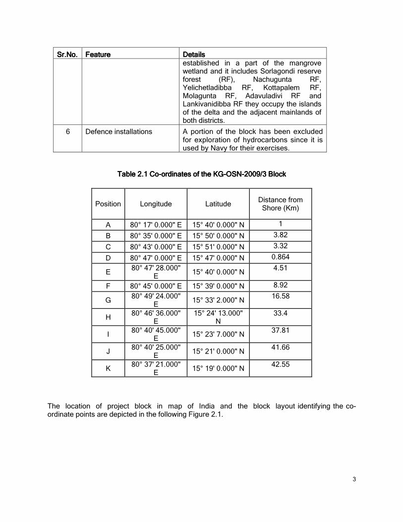
Table Table Table Table 2222.1.1.1.1 CoCoCoCo----ordinates of the KGordinates of the KGordinates of the KGordinates of the KG----OSNOSNOSNOSN----2009/3 Block2009/3 Block2009/3 Block2009/3 Block
Position Longitude Latitude Distance from
Shore (Km)
A 80° 17' 0.000" E 15° 40' 0.000" N 1
B 80° 35' 0.000" E 15° 50' 0.000" N 3.82
C 80° 43' 0.000" E 15° 51' 0.000" N 3.32
D 80° 47' 0.000" E 15° 47' 0.000" N 0.864
E 80° 47' 28.000"
E 15° 40' 0.000" N
4.51
F 80° 45' 0.000" E 15° 39' 0.000" N 8.92
G 80° 49' 24.000"
E 15° 33' 2.000" N
16.58
H 80° 46' 36.000"
E 15° 24' 13.000"
N 33.4
I 80° 40' 45.000"
E 15° 23' 7.000" N
37.81
J 80° 40' 25.000"
E 15° 21' 0.000" N
41.66
K 80° 37' 21.000"
E 15° 19' 0.000" N
42.55
The location of project block in map of India and the block layout identifying the co-ordinate points are depicted in the following Figure 2.1.
4
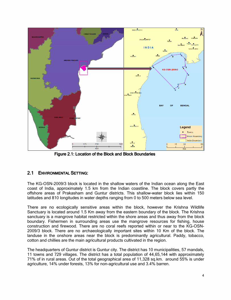
FFFFiiiiguregureguregure 2222....1: Loca1: Loca1: Loca1: Locattttiiiionononon ofofofof tttthehehehe BBBBllllockockockock andandandand BBBBllllockockockock BBBBoundaroundaroundaroundariiiieseseses
2.12.12.12.1 EEEENVIRONMENTAL NVIRONMENTAL NVIRONMENTAL NVIRONMENTAL SSSSETTINGETTINGETTINGETTING::::
The KG-OSN-2009/3 block is located in the shallow waters of the Indian ocean along the East coast of India, approximately 1.5 km from the Indian coastline. The block covers partly the offshore areas of Prakasham and Guntur districts. This shallow-water block lies within 150 latitudes and 810 longitudes in water depths ranging from 0 to 500 meters below sea level. There are no ecologically sensitive areas within the block, however the Krishna Wildlife Sanctuary is located around 1.5 Km away from the eastern boundary of the block. The Krishna sanctuary is a mangrove habitat restricted within the shore areas and thus away from the block boundary. Fishermen in surrounding areas use the mangrove resources for fishing, house construction and firewood. There are no coral reefs reported within or near to the KG-OSN-2009/3 block. There are no archaeologically important sites within 10 Km of the block. The landuse in the onshore areas near the block is predominantly agricultural. Paddy, tobacco, cotton and chillies are the main agricultural products cultivated in the region. The headquarters of Guntur district is Guntur city. The district has 10 municipalities, 57 mandals, 11 towns and 729 villages. The district has a total population of 44,65,144 with approximately 71% of in rural areas. Out of the total geographical area of 11,328 sq.km. around 55% is under agriculture, 14% under forests, 13% for non-agricultural use and 3.4% barren.

5
The Prakasam district with its headquarters in Ongle has 3 revenue divisions 56 mandals and 1011 villages. The population in the district is 3054941 with approximately 84% in rural areas. Out of the total geographical area of 17140 sq.km. around 51% is under agriculture, 22% under forests and 26% under non-agricultural use.
3333 PROJECT DESCRIPTION:PROJECT DESCRIPTION:PROJECT DESCRIPTION:PROJECT DESCRIPTION: The NE-SW-trending Krishna-Godavari basin is pericratonic basin situated on the eastern continental margin of India. The detailed geophysical surveys indicate the basin to be divisible into 3 sub basins viz., Krishna sub-basin, West Godavari sub-basin and East Godavari sub-basin. The offshore KG-OSN-2009/3 block falls within the Krishna sub-basin. The basin is divided into a number of rotated half grabens which are arranged in an en-echelon manner offset by major cross trends. The prospects have been identified on the basis of seismic vintage 2D data interpretation, and these prospects are given by area polygons in the map below (Figure - 3.1)
Figure Figure Figure Figure 3.13.13.13.1: Location of Hydrocarbon Leads within the Block: Location of Hydrocarbon Leads within the Block: Location of Hydrocarbon Leads within the Block: Location of Hydrocarbon Leads within the Block Geochemical analysis of Late Jurassic-Early Cretaceous sediments of wells Nellore-1, Sidhavaram-1, KS-3-1 & KS-4-1 has identified hydrocarbon source rock units (Barremian –Aptian-Albian) with fair potential for generation of hydrocarbons. The present day organic carbon content for this section ranges from 1-3% while the Hydrogen index values range from 100 to 300. The Tmax values vary between 425oC and 470oC. Significant maturation is indicated. Good source rock units in Cretaceous and older sediments were encountered in the well KS-3-1, in the offshore block adjacent to KG-OSN-2009/3 block offered. A pre-Albian sequence in the Interval 1510-1630 m was identified to be a good source rock. The organic carbon content for this interval ranges between 1.02% and 2.77% while the Hydrogen Index varies from 102 to 255 (average HI=187). The studies indicate that the Cretaceous sequence has potential to generate both oil and gas.
6
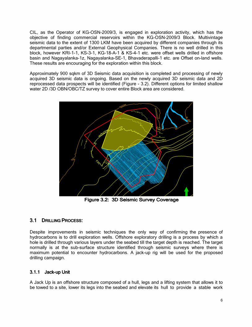
CIL, as the Operator of KG-OSN-2009/3, is engaged in exploration activity, which has the objective of finding commercial reservoirs within the KG-OSN-2009/3 Block. Multivintage seismic data to the extent of 1300 LKM have been acquired by different companies through its departmental parties and/or External Geophysical Companies. There is no well drilled in this block, however KRI-1-1, KS-3-1, KG-18-A-1 & KS-4-1 etc. were offset wells drilled in offshore basin and Nagayalanka-1z, Nagayalanka-SE-1, Bhavaderapalli-1 etc. are Offset on-land wells. These results are encouraging for the exploration within this block. Approximately 900 sqkm of 3D Seismic data acquisition is completed and processing of newly acquired 3D seismic data is ongoing. Based on the newly acquired 3D seismic data and 2D reprocessed data prospects will be identified (Figure - 3.2). Different options for limited shallow water 2D /3D OBN/OBC/TZ survey to cover entire Block area are considered.
Figure 3Figure 3Figure 3Figure 3.2.2.2.2: 3D Seismic: 3D Seismic: 3D Seismic: 3D Seismic Survey CoverageSurvey CoverageSurvey CoverageSurvey Coverage
3.13.13.13.1 DDDDRILLING RILLING RILLING RILLING PPPPROCESSROCESSROCESSROCESS::::
Despite improvements in seismic techniques the only way of confirming the presence of hydrocarbons is to drill exploration wells. Offshore exploratory drilling is a process by which a hole is drilled through various layers under the seabed till the target depth is reached. The target normally is at the sub-surface structure identified through seismic surveys where there is maximum potential to encounter hydrocarbons. A jack-up rig will be used for the proposed drilling campaign.
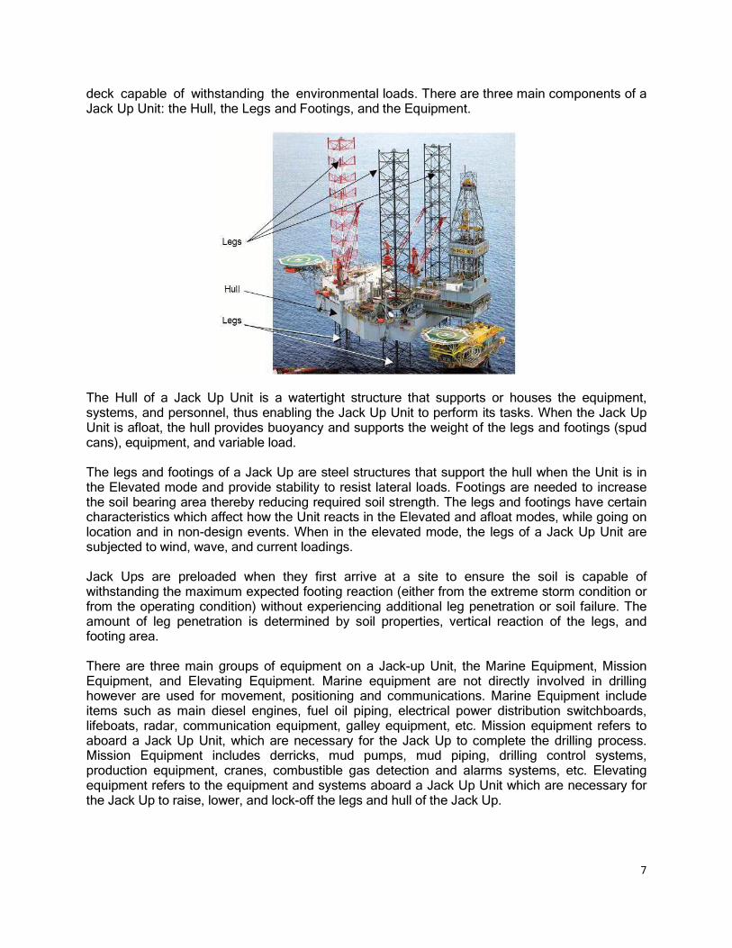
3.1.13.1.13.1.13.1.1 JaJaJaJacccckkkk----up Unitup Unitup Unitup Unit A Jack Up is an offshore structure composed of a hull, legs and a lifting system that allows it to be towed to a site, lower its legs into the seabed and elevate its hull to provide a stable work
7
deck capable of withstanding the environmental loads. There are three main components of a Jack Up Unit: the Hull, the Legs and Footings, and the Equipment.
The Hull of a Jack Up Unit is a watertight structure that supports or houses the equipment, systems, and personnel, thus enabling the Jack Up Unit to perform its tasks. When the Jack Up Unit is afloat, the hull provides buoyancy and supports the weight of the legs and footings (spud cans), equipment, and variable load. The legs and footings of a Jack Up are steel structures that support the hull when the Unit is in the Elevated mode and provide stability to resist lateral loads. Footings are needed to increase the soil bearing area thereby reducing required soil strength. The legs and footings have certain characteristics which affect how the Unit reacts in the Elevated and afloat modes, while going on location and in non-design events. When in the elevated mode, the legs of a Jack Up Unit are subjected to wind, wave, and current loadings. Jack Ups are preloaded when they first arrive at a site to ensure the soil is capable of withstanding the maximum expected footing reaction (either from the extreme storm condition or from the operating condition) without experiencing additional leg penetration or soil failure. The amount of leg penetration is determined by soil properties, vertical reaction of the legs, and footing area. There are three main groups of equipment on a Jack-up Unit, the Marine Equipment, Mission Equipment, and Elevating Equipment. Marine equipment are not directly involved in drilling however are used for movement, positioning and communications. Marine Equipment include items such as main diesel engines, fuel oil piping, electrical power distribution switchboards, lifeboats, radar, communication equipment, galley equipment, etc. Mission equipment refers to aboard a Jack Up Unit, which are necessary for the Jack Up to complete the drilling process. Mission Equipment includes derricks, mud pumps, mud piping, drilling control systems, production equipment, cranes, combustible gas detection and alarms systems, etc. Elevating equipment refers to the equipment and systems aboard a Jack Up Unit which are necessary for the Jack Up to raise, lower, and lock-off the legs and hull of the Jack Up.

8
3.1.23.1.23.1.23.1.2 OnOnOnOnsssshorehorehorehore FFFFaaaacccciliiliiliilittttiiiieeeessss Onshore facilities in the form of warehouse and jetty are required to support the drilling operation. The onshore facilities for KG-OSN-2009/3 are expected to be either at Kakinada port or Krishnapatnam port. However, Nizampatnam port can be used for small scale activities There will be two warehouses, i.e. one open and one closed for storing equipment’s and consumables for the proposed drilling. The open warehouse will be storing non-perishables like drill pipes and casings. The closed warehouse will be used for storing bentonite, chemicals, cement, lube oil etc. Equipments and consumables will be brought at the port via road or sea route. A jetty will be hired either on a sole user basis or shared during the drilling campaign. Material handling equipments like cranes, forklifts, trucks, pumps etc will be deployed for loading and unloading purposes. Skilled as well as unskilled workers will be employed for material management, security, loading and unloading activities and general administration. KKKKrrrriiiishnapashnapashnapashnapattttnnnnaaaammmm PPPPoooortrtrtrt Krishnapatnam is a deep water all weather port that is equipped to handle dry bulk like Iron Ore, Coal and containers and liquid bulk cargo. The port is located in the Nellore District of Andhra Pradesh. The port has four berths for handling cargo. The berths and stockyards are equipped with ship un-loaders and ship loaders, which can unload 3,000 Tonnes an hour and load 5,000 Tonnes an hour. There are also two mobile harbour cranes, stackers, re-claimers and conveyors. It has a capacity to handle up to 40,000 to 60,000 Tonnes per day. The port has well designed, closed as well as open storage area for efficient and safe handling of dry cargo commodities. The port has 50,000 sq. metres of closed warehouses and 23,00,000 sq. meters of open storage area.
KKKKakakakakiiiinadanadanadanada PPPPoooorrrrtttt Kakinada deep water port is situated in the east coast of India in Latitude 16o56’ N Longitude 82o15’E. This is an all-weather Lighterage Port developed in a naturally sheltered bay called as Godavari Sand Spit. There are about 98 Private Steel Dumb Barges with total carrying capacity of about 35,400 Tons. There are two mechanized barges with a carrying capacity of 250 tons each for supply of fresh water to ships. There are 55 warehouses with floor area of 25,586 sq.mt. There is 50,300 Sqm.of Open Stockyards close to water front available for stacking about 1,00,00 M.Tons of bulk cargoes.
3.1.33.1.33.1.33.1.3 SSSSupport upport upport upport VesVesVesVessssseeeelslslsls There will be 3 - 5 support vessels consisting of Anchor Handling Tug Supply (AHTS) vessels and Multi-purpose Support Vessels (MSV) that will be deployed for transferring equipments and consumables from the port to the jack-up unit. AHTS vessel is used for towing the jack-up unit to drilling location and anchoring it there. AHTS vessels are fitted with winches for towing and

9
anchor handling and an open stern to allow the decking of anchors. The multi-purpose support vessels are equipped with bulk storage spaces for pipes, casings, tubings, powders (cement, bentonite etc.), liquids (diesel and water), chemicals and other consumables. The support vessels are equipped with material handling equipments like cranes for unloading onto the jack-up unit. Pneumatic pumps are used for transfer of powder materials to silos present in jack-up unit. Water and diesel are transferred through pumps to tanks onboard the jack-up unit.
AAAAHHHHTTTTS S S S VVVVesselesselesselessel MMMMuuuullllttttiiii----purposepurposepurposepurpose SSSSupportupportupportupport VVVVesselesselesselessel
3.1.43.1.43.1.43.1.4 Drilling OpDrilling OpDrilling OpDrilling Opeeeerrrraaaattttionionionion The drilling process uses a rotating drill bit attached to the end of a drill pipe, referred to as the drill string. Drilling fluids are pumped down the drill string, through the drill bit and up the annular space between the drill string and the hole. As the bit turns, it breaks off small pieces of rock or drill cuttings, thus deepening the hole. The drilling fluid removes the cuttings from the hole, cools the drill bit, and maintains pressure control of the well as it is being drilled. As the hole becomes deeper, additional lengths of pipe are added to the drill string as necessary. Periodically, the drill string is removed and the unprotected section of the borehole is permanently stabilised by installing another type of pipe, called casing. Cement is then is pumped into the annular space between the casing and the borehole wall to secure the casing and seal off the upper part of the borehole. The casing maintains well-bore stability and pressure integrity. Each new portion of casing is smaller in diameter than the previous portion through which it is installed. The process of drilling and adding sections of casing continues until final well depth is reached. The maximum depth till which the wells in this block will be drilled is 5000 m. The well may be perforated with casing guns prior to the running of the tubing. The production casing will be cleaned up and the drilling fluid displaced with brine after the drilling operation is complete. A tubing string with a tubing hanger attached is run through the drilling riser and BOP, on either a completion riser or drill pipe, and landed in the wellhead. The pressure integrity of the tubing string, tubing hanger to wellhead seals and the production packer are then tested. The operation of the subsurface safety valve is also tested. Wireline plugs are set in the tailpipe of the packer and the tubing hanger and the completion riser is unlatched from the tubing hanger and retrieved. The BOP stack is unlatched from the wellhead and the stack and riser system is retrieved. A x-mas tree is installed over the well head. The well head is energised and all major functions are tested. The wireline plugs are retrieved from the tubing string. The perforating guns are run and the production casing is perforated. Flow from the well is then initiated and the well is cleaned up and tested.
10
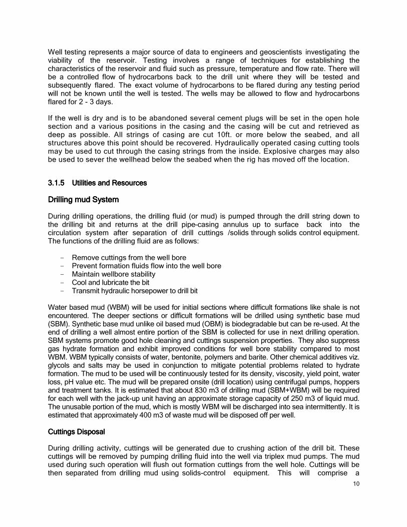
Well testing represents a major source of data to engineers and geoscientists investigating the viability of the reservoir. Testing involves a range of techniques for establishing the characteristics of the reservoir and fluid such as pressure, temperature and flow rate. There will be a controlled flow of hydrocarbons back to the drill unit where they will be tested and subsequently flared. The exact volume of hydrocarbons to be flared during any testing period will not be known until the well is tested. The wells may be allowed to flow and hydrocarbons flared for 2 - 3 days. If the well is dry and is to be abandoned several cement plugs will be set in the open hole section and a various positions in the casing and the casing will be cut and retrieved as deep as possible. All strings of casing are cut 10ft. or more below the seabed, and all structures above this point should be recovered. Hydraulically operated casing cutting tools may be used to cut through the casing strings from the inside. Explosive charges may also be used to sever the wellhead below the seabed when the rig has moved off the location.
3.1.53.1.53.1.53.1.5 UUUUttttiliiliiliilittttiiiieeeessss aaaand nd nd nd RRRResesesesourourourourcccceseseses DDDDrrrriiiilllllilililingngngng mudmudmudmud SSSSyyyyssssttttemememem During drilling operations, the drilling fluid (or mud) is pumped through the drill string down to the drilling bit and returns at the drill pipe–casing annulus up to surface back into the circulation system after separation of drill cuttings /solids through solids control equipment. The functions of the drilling fluid are as follows:
- Remove cuttings from the well bore - Prevent formation fluids flow into the well bore - Maintain wellbore stability - Cool and lubricate the bit - Transmit hydraulic horsepower to drill bit
Water based mud (WBM) will be used for initial sections where difficult formations like shale is not encountered. The deeper sections or difficult formations will be drilled using synthetic base mud (SBM). Synthetic base mud unlike oil based mud (OBM) is biodegradable but can be re-used. At the end of drilling a well almost entire portion of the SBM is collected for use in next drilling operation. SBM systems promote good hole cleaning and cuttings suspension properties. They also suppress gas hydrate formation and exhibit improved conditions for well bore stability compared to most WBM. WBM typically consists of water, bentonite, polymers and barite. Other chemical additives viz. glycols and salts may be used in conjunction to mitigate potential problems related to hydrate formation. The mud to be used will be continuously tested for its density, viscosity, yield point, water loss, pH value etc. The mud will be prepared onsite (drill location) using centrifugal pumps, hoppers and treatment tanks. It is estimated that about 830 m3 of drilling mud (SBM+WBM) will be required for each well with the jack-up unit having an approximate storage capacity of 250 m3 of liquid mud. The unusable portion of the mud, which is mostly WBM will be discharged into sea intermittently. It is estimated that approximately 400 m3 of waste mud will be disposed off per well. CCCCuuuuttittittittingsngsngsngs DDDDiiiispossposspossposaaaallll During drilling activity, cuttings will be generated due to crushing action of the drill bit. These cuttings will be removed by pumping drilling fluid into the well via triplex mud pumps. The mud used during such operation will flush out formation cuttings from the well hole. Cuttings will be then separated from drilling mud using solids-control equipment. This will comprise a

11
stepped system of processes consisting of linear motion vibrating screens called shale shakers, hydro-cyclones (including de-sanders and de-silters), and centrifuges to mechanically separate cuttings from the mud. Washed drill cuttings will be discharged off-shore into sea intermittently in accordance with MoEF guideline.
TTTTyyyyppppiiiicalcalcalcal DDDDrrrriiiilllll l l l CCCCuuuutttttitititingngngng SSSSeeeeparaparaparaparatitititionononon / / / / TTTTreareareareattttmemememennnntttt SSSSyyyyssssttttemememem It is estimated that approximately 200 m³ of drill cuttings will be generated from each well. The estimated quantities of mud and drill cuttings generated while drilling various sections has been described in TTTTabababablllleeee 3333....1111.
Table Table Table Table 3333....1111 Estimated Quantities of Drill Cuttings and Drilling Mud GeneratedEstimated Quantities of Drill Cuttings and Drilling Mud GeneratedEstimated Quantities of Drill Cuttings and Drilling Mud GeneratedEstimated Quantities of Drill Cuttings and Drilling Mud Generated
SSSSecececectitititionononon (i(i(i(inchenchenchenchessss))))
DDDDepepepeptttthhhh ((((m)m)m)m) VVVVoooollllumeumeumeume ooooffff CCCCuuuuttttttttiiiingsngsngsngs ((((mmmm³³³³))))
WasWasWasWastttteeee MMMMudududud GGGGeneneneneeeerarararattttedededed ((((mmmm³³³³))))
30” 130 12 40
17.5” 130 – ~650 80 125
12.25” 650 - 1500 64 135
8.5 1500 - 2500 36 80
CCCChemhemhemhemiiiical usagecal usagecal usagecal usage As discussed in the earlier sections various chemicals are used especially for attaining the desired properties of the drilling mud. The chemicals will be stored onboard the jack-up unit and replenished through MSV’s. The chemicals will be stored in a segregated manner with proper labelling. Material safety data sheets will be maintained for all hazardous chemicals. A typical list of chemicals that will be used during the drilling campaign along with estimated storage quantities is provided in TTTTabababablllleeee 3.23.23.23.2.

12
Table Table Table Table 3333....2222 Type and Quantities of Chemicals to be used during DrillingType and Quantities of Chemicals to be used during DrillingType and Quantities of Chemicals to be used during DrillingType and Quantities of Chemicals to be used during Drilling
TTTTyyyypepepepe QQQQuanuanuanuanttttitititityyyy
ForForForFor SSSSyyyynnnntttthehehehetitititicccc BBBBaseaseasease MMMMuuuudddd
Emulsifiers 10 MT
Gilsonite 5 MT
Lime 5 MT
Organophilic Bentonite MT
Barite 80 MT
Synthetic biodegradable Oil (Saraline 185V) 70 MT
ForForForFor WWWWaaaatttterererer basedbasedbasedbased MMMMudududud
Bentonite 5 MT
Caustic Soda 2 MT
Potassium Chloride 30 MT
Cellulose 5 MT
Xanthan Gum 5 MT
WaWaWaWatttterererer The MODU will have a typical storage capacity of 4000 - 5000 bbls (635 - 800 m³) of drill water and 800 - 900 bbls (130 – 145 m³) of fresh water. The drill water is mainly consumed for preparation of mud. Minor quantities are used for washing and cleaning the rig. The quantity of water required for preparation of WBM is around 800 bbls (130 m³) per day while for SBM it is 50 bbls (8 m³) per day. An estimated 20 m³/d of fresh water will be used for domestic consumption. PPPPoooowwwwerererer DG sets are incorporated in the MODU design / infrastructure for self sustained operations at sea. Approximately 4 MW of power generating capacity will be available at rig using approximately 14 KLD of High Speed Diesel. Supply vessels will transport the required fuel from one of the three ports. The support vessels will have their individual power generation equipment as per the engine capacity for the class of marine vessel
SSSSananananititititaaaattttiiiionononon There will be an On-board Sewage Treatment Plant to meet the requirements of the MARPOL Convention and the treated sewage will be discharged to sea. The on-board STP will typically consist of solids / oil separation and chemical oxidation to remove the organic load. The food

13
wastes will be macerated through a grinder and disposed offshore, which will serve as a food source for marine and aquatic life.
3.1.63.1.63.1.63.1.6 WasWasWasWastetetetessss aaaandndndnd EEEEmimimimissssssssiiiioooonsnsnsns AAAAiiiirrrr EEEEmmmmiiiissssssssiiiionsonsonsons The source of air emissions anticipated from offshore drilling are those resulting from combustion of fuel in Diesel Generator sets on the offshore rigs, exhaust emissions from supply vessels and due to helicopter movements. CIL proposes to use low sulphur HSD as fuel to the DG sets. The power generation capacity required is around 4 MW and the maximum fuel consumption will be around 14 KLD. The operational period at a single well will be around 25 – 30 days. Based on standard emission factors and fuel quality, the pollutant emission rate is tabulate below:
Fuel Fuel Fuel Fuel ttttyyyypepepepe MMMMax. ax. ax. ax. QQQQttttyyyy NNNNOOOOX X X X ((((gggg////s)s)s)s) CCCCOOOO ((((gggg////s)s)s)s) SSSSOOOO2222 ((((gggg////s)s)s)s) VVVVOOOOC C C C ((((gggg////s)s)s)s)
HSD (0.05%
Sulphur)
14 KLD 1.14 2.62 0.14 0.262
The DG sets will be equipped with stack suitable for a marine vessel operation and designed to international norms and in compliance to common industry practise. The engines will also be subjected to periodic maintenance to ensure efficient combustion and minimise emission of particulate matter and exhaust gases. NNNNooooiiiisesesese eeeemmmmiiiissssssssiiiionononon The major sources of noise generation from offshore development drilling operations are:
� Operation of DG sets on the rig.
� Supply Vessel, Helicopter Movements.
� Process of drilling and operation of mud pumps, shale shakers.
� Operation of moving machinery relating to the rig.
The amount of noise generated i.e.; the resulting noise level immediately near the place where the DG sets are positioned is dependent on the capacity of the DG set and to an extent on the manufacturer’s specifications. It is anticipated that the maximum noise levels generated due to all the above operations on the MODU is around 75 dB(A) at a distance of 15 m. The DG sets will be located in lower deck keeping adequate distance from living accommodation. The above noise levels are without mitigation measures. However, the DG sets in the MODU will be housed in acoustic control enclosures at the deck and the exhausts are provided with silencers. With the mitigation measures the noise levels will be further restricted within very short distance from the source. The personnel operating in the high noise level area will be given earplugs and muffs.

14
LLLLiiiiququququiiiidsdsdsds andandandand SSSSoooolilililidddd WaWaWaWasssstttteeee DDDDiiiischargesschargesschargesscharges During the operation of the offshore drilling rig, few liquid waste streams / products are generated. These wastes are stored, handled and disposed as per the requirements of MARPOL convention and in compliance to the applicable Indian regulation. The major liquid, solid waste discharges anticipated due to drilling operations include spent drilling mud and drill cuttings. All the major waste streams from drilling operations grouped under different categories are tabulated below:
SSSSourceourceourceource TTTTyyyypepepepe ofofofof WaWaWaWasssstttteeee
Drilling Process waste Spent drilling WBM
Spent drilling SBM
Drill cuttings
Spent Lubricating Oil
Wastes associated with supplied materials
Packaging wastes including drums, wooden pallets, plastic containers, plastic foils.
Industrial waste: Left over chemicals and materials, scrap metal, sludges, scales, batteries, spent acids, spent lubricants, filters etc.
Domestic waste: Sanitary waste and kitchen wastes and general rubbish.
Construction and maintenance wastes:
Cement, grit, blasting and painting wastes.
Drainage water Rainwater runoff, rig wash, cooling water
SSSSpentpentpentpent DDDDrrrriiiilllllilililingngngng MMMMudududud andandandand DDDDrrrriiiilllll l l l CCCCuuuutttttitititingsngsngsngs The details about discharge of spent drilling mud and drill cuttings have been described in sections 3.5.1 and 3.5.2. DDDDomesomesomesomestitititicccc WaWaWaWasssstttteeeewwwwaaaatttterererer The domestic effluents generated on the rig will be subjected to treatment in a STP, designed and operated as per the guidelines of International Maritime Organisation (IMP). The raw sewage will be treated in either extended aeration unit or electrocatalytic oxidation unit installed on the rig. RRRRiiiigggg WashWashWashWash WWWWaaaatttterererer The machinery space wash water will be routed through a closed drain to an oil separation unit where the free oil is removed as bilge. The bilge will be collected in a bilge tank and periodically treated and disposed to sea. The effluents discharged into the sea will have oil content less than 15 mg/l (as p er MARPOL).
15
4 PROPOSED TERMS OF REFERENCE FOR ENVIRONMENTAL IMPACT ASSESSMENT (EIA):
CEIL proposes to carry out drilling of up to ten (10 nos.) exploratory / appraisal wells in the delineated areas of KG-OSN-2009/1 offshore block. The interpretation of the 3D seismic survey results is presently ongoing and upon completion it will be used for finalizing drilling locations for exploratory wells. The proposed drilling campaigns are in the hydrocarbon leads located off the coast of Guntur & Prakasam districts, Andhra Pradesh. The EIA will focus on environment impacts from drilling activities in the hydrocarbon leads. The environmental and social baseline data will be collected from the entire block and surrounding areas however it is intended to carry our primary monitoring in the offshore areas within the block and on immediate onshore areas.
4.1 OBJECTIVE OF THE EIA: The primary objective of the said EIA is to identify and assess the potential impacts of drilling activities on the environment and propose management plans to mitigate adverse impacts and enhance beneficial impacts / recommend good practices. The overall objective can be broken down into the following key requirements:
(i) Carry out detailed scoping exercise to define the exact extent and scope of EIA and develop Terms of Reference (TOR) document as per the requirements of the EIA Notification 2006. This document is an outcome of the scoping exercise.
(ii) Collect, interpret and analyse environmental and social baseline data within the study area from secondary sources and through primary monitoring / consultation
(iii) Identify aspects of the project that could have interactions with the environment and social impacts on the local community
(iv) Identify and assess potential impacts from the project activities using various prediction tools
(v) Propose management plans for reducing / eliminating potential adverse environmental and social impacts and recommend mitigation measures in line with international good practice
(vi) Identify and quantify risks from potential accidents / emergency scenarios / disasters
(vii) Develop Emergency Response Plan (ERP) and Disaster Management Plan (DMP)
4.2 COMPONENTS OF THE EIA STUDY: The components of the EIA study will include:
• Determination of baseline conditions using primary data generation and secondary data available from existing reports and studies and historical data from government published reports
• Detailed description of all elements of the project activities during the rig mobilisation, drilling and post drilling phases. The elements to be analyzed will include the

16
infrastructures of the project including supply vessels, navigational routes, waste collection & disposal and management and utility requirements e.g. power generation, material handling etc.
• Identifying the sources of pollution and assessing the impacts on the environment due to proposed exploratory/appraisal drilling project.
• Preparation of EIA and EMP documents with recommendations on preventive and mitigation measures for limiting the impact on environment to the desired level during various stages of project.
• Risk Assessment (RA) and Disaster Management Plan (DMP) describing the probable risks and preventive & precautionary measures to be followed in the event of emergency situations such as accidents, fire, oil spills, blowouts etc.
4.2.14.2.14.2.14.2.1 Environmental & Social Baseline Status:Environmental & Social Baseline Status:Environmental & Social Baseline Status:Environmental & Social Baseline Status: The environmental and social baseline status will be determined for the project area as well as surroundings. Although the entire project area is offshore yet important features on the land and in inter-tidal & coastal areas needs to be studied e.g. ecologically sensitive habitats, marine navigation routes, near-shore and deep sea fishing practices, archaeological sites, coastal regulatory zones, defence installations and other sites having environmental & social significance. The baseline data collection / collation / generation required for assessing and evaluating impacts are presented in this section. It is to be noted that the typical data / information required for carrying out the environmental baseline is detailed below and normally consists of information from primary and secondary sources (including information available with CIL). The specific data / information required to be collected through primary sampling is detailed in Table-4.1.
Physical Environment:Physical Environment:Physical Environment:Physical Environment:
� Regional SettingRegional SettingRegional SettingRegional Setting � geography and geomorphology � Demarcation of coastal regulation zone � Coastal sensitivity mapping
� Oceanography Oceanography Oceanography Oceanography
� Bathymetry � Sea surface temperature � Sea salinity � Wave characteristics � Sea currents and tides � Sediment movement
� Climate and MeteorologyClimate and MeteorologyClimate and MeteorologyClimate and Meteorology
� Climatic pattern � Ambient temperature � Relative humidity � Rainfall � Regional wind patterns (wind speed & direction)
� Ambient Air QualityAmbient Air QualityAmbient Air QualityAmbient Air Quality

17
� Off-shore � On-shore
� Marine Water QualityMarine Water QualityMarine Water QualityMarine Water Quality
� Physical characteristics of water column (temperature, salinity & density at various depths)
� Chemical characteristics of water column (pH, DO levels, TSS, nutrient levels, heavy metals, TPH)
� Sediment qualitySediment qualitySediment qualitySediment quality
� Physical characteristics � Chemical Characteristics
� Natural HazardsNatural HazardsNatural HazardsNatural Hazards
� Seismic Activities � Seasonal Storms & Cyclones � Tsunamis & Tidal / Surge Waves
Biological environment:Biological environment:Biological environment:Biological environment:
� Land based and coastal ecosystemsLand based and coastal ecosystemsLand based and coastal ecosystemsLand based and coastal ecosystems
� Mangrove & littoral ecosystems � Floral & faunal diversity
� Marine EcosystemMarine EcosystemMarine EcosystemMarine Ecosystem
� Planktons (phytoplankton & zooplanktons) � Benthic fauna � Marine flora (sea grasses) � Marine fauna (marine mammals, marine reptiles, fishes) � Corals � Special emphasis on protected areas (demarcation), species of conservation
concerns
SocioSocioSocioSocio----economic Environment:economic Environment:economic Environment:economic Environment:
� Shared infrastructureShared infrastructureShared infrastructureShared infrastructure � Port facilities � International & national shipping routes and volumes � Fishing areas within the block
� Demographic profileDemographic profileDemographic profileDemographic profile
� Education & literacyEducation & literacyEducation & literacyEducation & literacy
� Economic Economic Economic Economic activities & livelihood patternactivities & livelihood patternactivities & livelihood patternactivities & livelihood pattern including near-shore and deep sea fishing
practices
� SocioSocioSocioSocio----economic Infrastructure & Indicatorseconomic Infrastructure & Indicatorseconomic Infrastructure & Indicatorseconomic Infrastructure & Indicators � Healthcare facilities � Education facilities � Drinking water & sanitation � Agriculture

18
� Tourism � Fisheries � Transportation facilities � IT & communication
� Stakeholder AnalysisStakeholder AnalysisStakeholder AnalysisStakeholder Analysis
� Key stakeholders � Key stakeholder’s profile � Stakeholder consultation feedback
Legal & Institutional FrameworkLegal & Institutional FrameworkLegal & Institutional FrameworkLegal & Institutional Framework
� Regulatory Control as applicable to the project, including details of permits required to
be obtained � International Conventions � Institutional Framework – Enforcement Agencies
4.2.24.2.24.2.24.2.2 Primary Baseline Monitoring:Primary Baseline Monitoring:Primary Baseline Monitoring:Primary Baseline Monitoring:
The drilling at the block is expected to be during post-monsoon or winter season and thus the primary environmental baseline monitoring is intended during post-monsoon or winter. The aim of primary baseline monitoring is to obtain field data and collate and compile data from secondary sources that are required for carrying out impact assessment. The primary baseline monitoring requirements as envisaged has been defined in the following table.
Table 4.1 Primary baseline monitoring parameters and frequencyTable 4.1 Primary baseline monitoring parameters and frequencyTable 4.1 Primary baseline monitoring parameters and frequencyTable 4.1 Primary baseline monitoring parameters and frequency
S.S.S.S.NoNoNoNo.... AttributeAttributeAttributeAttribute No. of LocationsNo. of LocationsNo. of LocationsNo. of Locations FrequencyFrequencyFrequencyFrequency ParametersParametersParametersParameters
1 Micro-meteorology
2 (1 offshore & 1 onshore)
Continuous for 10 days
Temperature, relative humidity, wind speed, wind direction, rainfall and cloud cover
2 Ambient air quality (Onshore)
4 onshore location along the coast
2 days/week x 4 weeks for onshore locations
All parameters of NAAQS Day & Night time Noise
Ambient air quality (Offshore)
1 location offshore to be located in the sampling vessel
Once at one location over a 24 hour period
All parameters of NAAQS Day & Night time Noise
3 Marine water quality
5 Grab samples from 3 different depths once at each location
Temperature, pH, salinity, Dissolved Oxygen, Suspended Solids, Turbidity and Visibility, Nitrites & Nitrates, Phosphates, Silicates, Total Petroleum (TPH) Hydrocarbons, all Heavy Metals, chlorophyll-a, phytoplankton, zooplankton
4 Marine sediment
5 (3 middle of block and 2 near
Grab samples once at each
Particle size, % Sand, % Silt, % Clay, TPH, Poly-nuclear Aromatic

19
S.S.S.S.NoNoNoNo.... AttributeAttributeAttributeAttribute No. of LocationsNo. of LocationsNo. of LocationsNo. of Locations FrequencyFrequencyFrequencyFrequency ParametersParametersParametersParameters
quality shore) location Hydrocarbons (PAH), all Heavy Metals, micro & macro benthos encountered
5 Larger marine fauna
Entire block Observation Notes on number & type of larger marine faunal species observed during the primary monitoring study
4.2.34.2.34.2.34.2.3 Environmental & Social Impact Assessment:Environmental & Social Impact Assessment:Environmental & Social Impact Assessment:Environmental & Social Impact Assessment:
Environmental and social impacts from the project activities during its various stages should be identified, interpreted and analysed using both quantitative and qualitative techniques as required. The impacts identified and evaluated should include direct & indirect impacts as well as adverse & beneficial impacts. An overall evaluation should be carried out of all the impacts to and prioritised based on their potentiality. The extent and potential consequences of the impacts should be compared against national and international standards, protocols and guidelines. An indicative list (but not limited to) of various impacts that needs to be identified and analysed is shown below.
� Potential impacts on air quality as a result of emissions from power generation sources on rig, helicopter, support vessels, fugitive emissions during material handling and during test flaring. Air dispersion modelling is suggested for assessing increase in concentration levels of pollutants in ambient air if any.
� Potential impact on noise quality and vibrations from sources like the equipment on-
board the rig, helicopter, support vessels etc. Noise dissipation modelling. Underwater noise propagation due to drilling activities and its potential impacts should be assessed.
� Potential impact on marine water quality from discharges to sea of treated effluents and
drill cuttings. Potential impacts from accidental spills of fuel, drilling mud, lubricating oil and other chemicals should be assessed. Dispersion patterns of diesel, lubricating oil, drilling mud, drill cuttings and other chemicals should be analysed by using simulation models. Resultant concentrations of pollutants in marine water resulting from planned discharges and accidental spills should be evaluated and the mitigation measures should recommend discharge limits for minimising disturbance to baseline conditions. Any potential impact on marine micro & macro biota due to changes in marine water quality based on their habitat study should be assessed.
� Impacts on coastal ecology and landscape from unlikely major spill events like blow outs
or structural failure.
� Potential impact on sediment quality from planned discharges and accidentals spills. Sediment dispersion modelling should be undertaken to assess sedimentation characteristics of drill cuttings and residual drilling mud and probable changes in sediment quality as a result of such discharges. Potential impact on benthos should be assessed due to sedimentation from planned discharges and accidental spills.
� Potential ecological impacts on marine flora (sea grasses, mangroves, phyto-planktons),
marine fauna (mammals, fishes, reptiles, corals, zooplanktons etc.) and coastal flora &

20
fauna from drilling operations. The impacts could be due to disturbance, noise & illumination caused by rig commissioning activities, drilling operations, testing operations and de-commissioning. The impacts should be assessed based on study of habitat and behavioural patterns.
� Potential socio-economic impacts from the presence of the drilling rig, deployment of
supply vessels, restriction on marine traffic, interference with commercial fishing, use of common infrastructure (e.g. port facility).
4.3 MANAGEMENT & CONTROL OF IMPACTS A detailed environmental and social management plan should be proposed to mitigate adverse impacts and recommend good practices. The mitigation measures should be targeted at reducing impacts to acceptable limits as prescribed in various national and international standards and guidelines. The mitigation measures if implemented should be able to effectively eliminate or minimise adverse impacts on receptors. The environment & social management plan should also have recommendations for improving environmental performance and good practices adopted by progressive companies. The ESMP should provide recommendations for all phases of the drilling project cycle i.e. commissioning, drilling, testing and decommissioning. Risk mitigation measures are to be proposed to ALARP levels. Separate management plans shall be prepared for mitigating various risks i.e. emergency response plan (ERP), disaster management plan (DMP) and oil spill contingency plan (OSCP). Environmental monitoring plan shall be prepared to ensure compliance to all regulatory and other requirements as well as of parameters that will indicate that the impacts are within acceptable limits.
4.4 QUANTITATIVE RISK ASSESSMENT The quantitative risk assessment (QRA) should aim to provide a systematic analysis of the major risks that may arise as a result of offshore exploration activities. The QRA processes should outline rational evaluations of the identified risks based on their significance and provide the outline for appropriate preventive and risk mitigation measures. The preventive and risk mitigation measures should ensure that the project risks stay below As Low As Reasonably Practicable (ALARP) levels at all times during project implementation. In addition, the QRA should also help in assessing risks arising from potential emergency situations like large oil spills, well blow outs, H2S release, vessel collisions, helicopter crash, fire & explosion etc. as well as from natural disasters like tsunamis, cyclones and earth quakes. The assessments should be followed with developing structured Emergency Response Plan (ERP), Oil Spill Response Plan (OSRP) and Disaster Management Plan (DMP) to restrict damage to personnel, infrastructure and the environment. These plans should define the responsibilities and resources available to respond to the different types of emergencies envisaged. Training exercises and other preventive management measures should be proposed in a manner that all personnel are familiar with their responsibilities and that communication links are functioning effectively.
4.4.14.4.14.4.14.4.1 Public Hearing:Public Hearing:Public Hearing:Public Hearing: The KG-OSN-2004/1 Block is entirely offshore and thus limited interactions with the public is envisaged during the drilling operations. The MODU will be towed via the sea route and anchored at drilling locations. Resources like water and fuel will be brought to the MODU through supply vessels from a nearest port. The block is in offshore areas of Guntur & Prakasam
21
districts however considering the limited public interfaces with the project it is thus suggested that the public hearing be carried out at one location either in the Guntur or the Prakasam district.
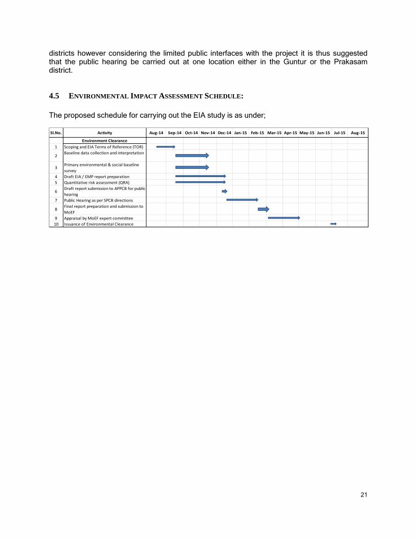
4.5 ENVIRONMENTAL IMPACT ASSESSMENT SCHEDULE: The proposed schedule for carrying out the EIA study is as under; Sl.No. Activity Aug-14 Sep-14 Oct-14 Nov-14 Dec-14 Jan-15 Feb-15 Mar-15 Apr-15 May-15 Jun-15 Jul-15 Aug-15
Environment Clearance
1 Scoping and EIA Terms of Reference (TOR)
2Baseline data collection and interpretation
3Primary environmental & social baseline
survey
4 Draft EIA / EMP report preparation
5 Quantitative risk assessment (QRA)
6Draft report submission to APPCB for public
hearing
7 Public Hearing as per SPCB directions
8Final report preparation and submission to
MoEF
9 Appraisal by MoEF expert committee
10 Issuance of Environmental Clearance