proposed text for 2.5gbase-x...
TRANSCRIPT

802.3cb 2.5GBASE-X PCS/PMA proposed text for draft 0.1
IEEE 802.3cb – CU4HDD 1 14 March 2016
Proposed Text for 2.5GBASE-X PCS/PMA
William Lo Marvell

802.3cb 2.5GBASE-X PCS/PMA proposed text for draft 0.1
IEEE 802.3cb – CU4HDD 2 14 March 2016
To make editing instructions easier to understand for the purposes of assembling the initial Framemaker file the following conventions are used below: Table 125–1 – Highlight yellow means it cross references something in the 802.3cb draft specification. 1.2.3 – Green text means it references a Clause in IEEE 802.3 that does not appear in the 802.3cb draft specification. Insert these 2 rows in table 1-23 – Red text means editing instructions for person assembling the initial Framemaker file and should not appear in the document. Underlined blue text – New text inserted in existing clauses. Note that text in new clauses are not underlined. Cross out purple text – Text that should be deleted in existing clauses. Editor’s Note: Insert following rows in Table 1-23 – Bold italic font look like editing instructions for the person assembling the Framemaker file, but they are instructions for the IEEE editor and are actually part of the of the 802.3cb draft specification as bold italic font. Leave these as is in the text and do not delete or take any action on these. Only act on the editing instructions in red.

802.3cb 2.5GBASE-X PCS/PMA proposed text for draft 0.1
IEEE 802.3cb – CU4HDD 3 14 March 2016
Ignore this page with table of contents. It is included here to make sure all the headings in this document are formatted properly as headings. The final assembly of all the clauses in Framemaker should build the table of content in that document
Contents 200 Physical Coding Sublayer (PCS) and Physical Medium Attachment (PMA) sublayer for 8B/10B, type 2.5GBASE-X 4
200.1 Overview ............................................................................................................................................................. 4 200.1.1 Scope ......................................................................................................................................................... 4 200.1.2 Relationship of 2.5GBASE-X to other standards ........................................................................................ 4 200.1.3 Summary of 2.5GBASE-X sublayers .......................................................................................................... 4
200.1.3.1 Physical Coding Sublayer (PCS)............................................................................................................ 5 200.1.3.2 Physical Medium Attachment (PMA) sublayer ....................................................................................... 5
200.1.4 Inter-sublayer interfaces ............................................................................................................................. 5 200.1.5 Functional Block Diagram ........................................................................................................................... 6
200.2 Physical Coding Sublayer (PCS) ......................................................................................................................... 7 200.2.1 PCS service interface (XGMII).................................................................................................................... 7 200.2.2 Functions within the PCS ........................................................................................................................... 7 200.2.3 Use of code-groups .................................................................................................................................... 7 200.2.4 XGMII to 2.5GPII mapping ......................................................................................................................... 8
200.2.4.1 2.5Gb/s PCS Internal Interface (2.5GPII) ............................................................................................... 8 200.2.4.2 Word Encode ......................................................................................................................................... 9 200.2.4.3 Word Serializer..................................................................................................................................... 10 200.2.4.4 Word Alignment.................................................................................................................................... 10 200.2.4.5 Word Decode ....................................................................................................................................... 11
200.2.5 8B/10B transmission code ........................................................................................................................ 12 200.2.5.1 Notation conventions ............................................................................................................................ 12 200.2.5.2 Transmission order .............................................................................................................................. 12 200.2.5.3 Generating and checking Code-groups ................................................................................................ 12 200.2.5.4 Ordered_sets ....................................................................................................................................... 13 200.2.5.5 Comma considerations ........................................................................................................................ 13 200.2.5.6 Sequence (/Q/) ..................................................................................................................................... 13 200.2.5.7 Data (/D/) ............................................................................................................................................. 14 200.2.5.8 Idle (/I/) ................................................................................................................................................. 14 200.2.5.9 Low Power Idle (/LI/) ............................................................................................................................ 14 200.2.5.10 Start_of_Packet (SPD) delimiter ...................................................................................................... 14 200.2.5.11 End_of_Packet delimiter (EPD) ....................................................................................................... 14 200.2.5.12 Error_Propagation (/V/) .................................................................................................................... 15
200.2.6 Detailed functions and state diagrams ...................................................................................................... 15 200.2.6.1 State variables ..................................................................................................................................... 15 200.2.6.2 State diagrams ..................................................................................................................................... 24
200.3 Physical Medium Attachment (PMA) sublayer .................................................................................................. 38 200.3.1 Service Interface....................................................................................................................................... 38
200.3.1.1 PMA_UNITDATA.request .................................................................................................................... 38 200.3.1.2 PMA_UNITDATA.indication ................................................................................................................. 38
200.3.2 Functions within the PMA ......................................................................................................................... 39 200.3.2.1 Data delay ............................................................................................................................................ 39 200.3.2.2 PMA transmit function .......................................................................................................................... 39 200.3.2.3 PMA receive function ........................................................................................................................... 39 200.3.2.4 Code-group alignment .......................................................................................................................... 39
200.3.3 Loopback mode ........................................................................................................................................ 39 200.3.3.1 Receiver considerations ....................................................................................................................... 39 200.3.3.2 Transmitter considerations ................................................................................................................... 40
200.3.4 Test functions ........................................................................................................................................... 40 200.4 Compatibility considerations .............................................................................................................................. 40 200.5 Delay constraints ............................................................................................................................................... 40 200.6 Environmental specifications ............................................................................................................................. 40 200.7 Protocol implementation conformance statement (PICS) proforma for Clause 200, Physical Coding Sublayer (PCS) and Physical Medium Attachment (PMA) sublayer, type 2.5GBASE-X ................................................................ 40

802.3cb 2.5GBASE-X PCS/PMA proposed text for draft 0.1
IEEE 802.3cb – CU4HDD 4 14 March 2016
200 Physical Coding Sublayer (PCS) and Physical Medium Attachment (PMA) sublayer for 8B/10B, type 2.5GBASE-X
200.1 Overview
200.1.1 Scope
This clause specifies the Physical Coding Sublayer (PCS) and the Physical Medium Attachment (PMA) sublayer that are common to a family of 2.5 Gb/s Physical Layer implementations known as 2.5GBASE-X. The
2.5GBASE-X PCS and 2.5GBASE-X PMA are sublayers of the 2.5 Gb/s BASE-X PHY listed in Table 125–1. The term 2.5GBASE-X is used when referring generally to Physical Layers using the PCS and PMA defined in this clause. 200.1.2 Relationship of 2.5GBASE-X to other standards
Figure 125–1 depicts the relationships among the 2.5GBASE-X sublayers, the Ethernet MAC and reconciliation layers, and the higher layers. The 2.5GBASE-X service interface is the XGMII, which is defined in Clause 46. 200.1.3 Summary of 2.5GBASE-X sublayers
Figure 200-1 shows the relationship of the 2.5GBASE-X PCS sublayer with other sublayers to the ISO Open System Interconnection (OSI) reference model. FM editor’s note: Copy figure 125-1 from 802.3bz and draw diagram as sketched below:
X
PMA
PMD
X
Figure 200-1 2.5GBASE-X PCS and PMA relationship to the ISO/IEC Open Systems
Interconnection (OSI) reference model and IEEE 802.3 Ethernet model

802.3cb 2.5GBASE-X PCS/PMA proposed text for draft 0.1
IEEE 802.3cb – CU4HDD 5 14 March 2016
200.1.3.1 Physical Coding Sublayer (PCS)
The PCS service interface is the XGMII, which is defined in Clause 46 running at 2.5Gb/s. The 2.5GBASE-X PCS provides all services required by the XGMII including Encoding (decoding) of XGMII data octets to (from) ten-bit code-groups (8B/10B) for communication with the underlying PMA. 200.1.3.2 Physical Medium Attachment (PMA) sublayer
The PMA provides a medium-independent means for the PCS to support the use of serial-bit oriented physical media. The 2.5GBASE-X PMA performs the following functions:
a) Mapping of transmit and receive code-groups between the PCS and PMA via the PMA Service Interface b) Serialization (deserialization) of code-groups for transmission (reception) on the underlying serial PMD c) Recovery of clock from the 8B/10B-coded data supplied by the PMD d) Mapping of transmit and receive bits between the PMA and PMD via the PMD Service Interface
200.1.4 Inter-sublayer interfaces
The upper interface of the PCS may connect to the Reconciliation Sublayer through the XGMII. The lower interface of the PCS connects to the PMA sublayer to support a PMD. The 2.5GBASE-X PCS has a nominal rate at the PMA service interface of 3.125 Gb/s, which provides capacity for the MAC data rate of 2.5 Gb/s. It is important to note that, while this specification defines interfaces in terms of bits, octets, and frames, implementations may choose other data-path widths for implementation convenience.

802.3cb 2.5GBASE-X PCS/PMA proposed text for draft 0.1
IEEE 802.3cb – CU4HDD 6 14 March 2016
200.1.5 Functional Block Diagram
Figure 200-2 provides a functional block diagram of the 2.5GBASE-X PHY.
TXD<31:0>
TXC<3:0>
TX_CLK
RXD<31:0>
RXC<3:0>
RX_CLK
tpd<3:0><7:0>
tp_en<3:0>
tp_er<3:0>
tpd<7:0>
tp_en
tp_er
rpd<3:0><7:0>
rp_dv<3:0>
rp_er<3:0>
rpd<7:0>
rp_dv
rp_er
tx_code_group<9:0> rx_code_group<9:0>
tx_bit rx_bit
Transmit Receive
Word Decode
Word Alignment
Receive
Synchronization
Word Serializer
Word Encode
Transmit
XGMII
PCS
Transmit Receive
PMA
PMD
MDI
Figure 200-2 Functional block diagram

802.3cb 2.5GBASE-X PCS/PMA proposed text for draft 0.1
IEEE 802.3cb – CU4HDD 7 14 March 2016
200.2 Physical Coding Sublayer (PCS)
200.2.1 PCS service interface (XGMII)
The PCS service interface allows the 2.5GBASE-X PCS to transfer information to and from a PCS client. A PCS client is generally the Reconciliation Sublayer. The PCS Interface is precisely defined as the 10 Gigabit Media Independent Interface (XGMII) scaled to run at 2.5Gb/s in Clause 46. 200.2.2 Functions within the PCS
The PCS includes the Word Encode, Word Serializer, Transmit, Synchronization, Receive, Word Alignment, and Word Decode processes for 2.5GBASE-X. The PCS shields the RS (and MAC) from the specific nature of the underlying channel. When communicating with the XGMII, the PCS uses, in each direction, 32 data signals (TXD <31:0> and RXD <31:0>), four control signals (TXC <3:0> and RXC <3:0>), and a clock (TX_CLK and RX_CLK). When communicating with the PMA, the PCS uses a ten-bit wide, synchronous data path, which conveys ten-bit code-groups. At the PMA Service Interface, code-group alignment and MAC packet delimiting are made possible by embedding special non-data code-groups in the transmitted code-group stream. The PCS provides the functions necessary to map packets between the XGMII format and the PMA service interface format. The Word Encode process continuously generates four 2.5GPII symbols based upon the TXD <31:0> and TXC <3:0> signals on the XGMII, sending them to the Word Serializer process. The Word Serializer process takes the four 2.5GPII symbols and outputs them one 2.5GPII symbol at a time to the PCS Transmit Process. The PCS Transmit process continuously generates code-groups based upon the tpd<7:0>, tp_en, and tp_er signals on the 2.5GPII, sending them immediately to the PMA Service Interface via the PMA_UNITDATA.request primitive. The PCS Synchronization process continuously accepts code-groups via the PMA_UNITDATA.indication primitive and conveys received code-groups to the PCS Receive process via the SYNC_UNITDATA.indicate primitive. The PCS Synchronization process sets the sync_status flag toindicate whether the PMA is functioning dependably. The PCS Receive process continuously accepts code-groups via the SYNC_UNITDATA.indicate primitive. The PCS Receive process monitors these code-groups and generates rpd<7:0>, rp_dv, and rp_er on the 2.5GPII. The Word Aligment process queues the received 2.5GPII symbols and aligns them in groups of four 2.5GPII symbols. Symbols may be deleted or idle symbols added in order to do the alignment. The Word Decode process continuously accepts the four 2.5GPII symbols from the Word Alignment process and generates RXD <31:0> and RXC <3:0> on the XGMII. All PCS processes are described in detail in the state diagrams in 200.2.6.2. 200.2.3 Use of code-groups
The transmission code used by the PCS, referred to as 8B/10B, is identical to that specified in Clause 36. The PCS maps XGMII characters into an intermediate 2.5GPII which is then mapped to 10-bit code-groups, and vice versa, using the 8B/10B block coding scheme. Implicit in the definition of a code-group is an establishment of code-group boundaries by a PCS Synchronization process. The 8B/10B transmission code as well as the rules by which the PCS ENCODE and DECODE functions generate, manipulate, and interpret code-groups are specified in 200.2.5. The XGMII to 2.5GPII mapping and vice versa are specified in 200.2.4. Code-groups and the 2.5GPII are unobservable and have no meaning outside the PCS.

802.3cb 2.5GBASE-X PCS/PMA proposed text for draft 0.1
IEEE 802.3cb – CU4HDD 8 14 March 2016
200.2.4 XGMII to 2.5GPII mapping
The Word Encode, Word Serializer, Word Alignment, and Word Decode processes together define the XGMII to 2.5GPII mapping. This mapping function formats and serializes/de-derializes the data between the four XGMII lanes and the single lane of the PCS transmit/receive process. 200.2.4.1 2.5Gb/s PCS Internal Interface (2.5GPII)
The 2.5Gb/s PCS Internal Interface (2.5GPII) is a logical interface that is internal to the 2.5GBASE-X PCS and exists solely for the purposes of defining the 2.5GBASE-X PCS functionality. Physical implementation of the 2.5GPII is optional and is not exposed outside of the PCS. The 2.5GPII consists of the following variables: tp_en, tp_er, tpd<7:0>, rp_dv, rp_er, rpd<7:0> and its encoding is similar but not identical to the GMII in clause 35. The permissible encodings are shown in Table 200-1 and Table 200-2. A 2.5GPII symbol is defined to be a set of tp_en, tp_er, tpd<7:0> variables or rp_dv, rp_er, rpd<7:0> variables. The Word Encode and Word Decode processes maps between the four XGMII lanes to four 2.5GPII symbols. The four 2.5GPII symbols are indexed as tp_en<3:0>, tp_er<3:0>, tpd<3:0><7:0>, rp_dv<3:0>, rp_er<3:0>, rpd<3:0><7:0>. The nominal rate of operation is 12.8ns +/- 0.01% The Word Serializer and Word Alignment processes serializes/de-serializes four 2.5GPII symbols to/from four consecutive single 2.5GPII symbols. The nominal rate of operation of the single 2.5GPII symbol is 3.2ns +/- 0.01%.
Table 200-1 Permissible encodings of tpd<7:0>, tp_en, tp_er
tp_en tp_er tpd<7:0> Description Abbreviation
0 0 0x00 to 0xFF Normal inter-frame Idle
0 1 0x00 Reserved
0 1 0x01 Assert LPI LPI
0 1 0x02 to 0x9B Reserved
0 1 0x9C Sequence Seq
0 1 0x9D to 0xFF Reserved
1 0 00 to FF Data Data x
1 1 0x00 to 0xFF Transmit Error Err
Table 200-2 Permissible encodings of rpd<7:0>, rp_dv, rp_er
rp_dv rp_er rpd<7:0> Description Abbreviation
0 0 0x00 to 0xFF Normal inter-frame idle
0 1 0x00 Reserved
0 1 0x01 Assert LPI LPI
0 1 0x02 to 0x0D Reserved
0 1 0x0E False carrier indication
0 1 0x0F Carrier Extend (odd byte packets) CE
0 1 0x10 to 0x9B Reserved
0 1 0x9C Sequence Seq
0 1 0x9D to 0xFF Reserved
1 0 00 to FF Data Data x
1 1 0x00 to 0xFF Receive Error Err

802.3cb 2.5GBASE-X PCS/PMA proposed text for draft 0.1
IEEE 802.3cb – CU4HDD 9 14 March 2016
200.2.4.2 Word Encode
The Word Encode process maps the four XGMII lanes onto four 2.5GPII symbols as shown in Table 200-3. The XGMII encoding is specified in Table 46-3. The 2.5GPII encoding is specified in Table 200-1. The mapping of the sequence ordered set is dependent on the current state of the wencode_state variable as shown in column 5. The state of wencode_state is updated once the mapping occurs per the last column.
Table 200-3 Word Encode Mapping
XGMII 2.5GPII
Lane 0 Lane 1 Lane 2 Lane 3 wencode_
state 2.5GPII<0> 2.5GPII<1> 2.5GPII<2> 2.5GPII<3> wencode_
state
Data A/Err Data B/Err Data C/Err Data D/Err X Data A/Err Data B/Err Data C/Err Data D/Err DATA
Idle Idle Idle Idle X Idle Idle Idle Idle IDLE
LPI LPI LPI LPI X LPI LPI LPI LPI DATA
SOP Data A/Err Data B/Err Data C/Err X 0x55 Data Data A/Err Data B/Err Data C/Err DATA
Terminate Idle Idle Idle X Idle Idle Idle Idle IDLE
Data A/Err Terminate Idle Idle X Data A/Err Idle Idle Idle DATA
Data A/Err Data B/Err Terminate Idle X Data A/Err Data B/Err Idle Idle DATA
Data A/Err Data B/Err Data C/Err Terminate X Data A/Err Data B/Err Data C/Err Idle DATA
Sequence Data X Data Y Data Z IDLE Seq Data S0 Seq Data S1 SEQ
Sequence Data X Data Y Data Z SEQ Seq Prev Data S2 Seq Prev Data S3 IDLE
Sequence Data X Data Y Data Z DATA Idle Idle Idle Idle IDLE
else Err Err Err Err DATA
A sequence ordered set |Q| appears to the PMA as /K28.5/W/K28.5/W/K28.5/W/K28.5/W/. On the 2.5GPII this appears as Seq, Data S0, Seq Data S1, Seq, Data S2, Seq, Data S3. The same sequence ordered-set is assumed to be repeating over multiple XGMII cycles. Every other consecutive Sequence ordered-set on the XGMII is ignored. If a Sequence ordered-set occurs over odd number of cycles on the XGMII then the final one will be truncated as Seq, Data S0, Seq Data S1 and Seq, Data S2, Seq, Data S3 are not sent. The 24 bit Data X, Data Y, and Data Z from the sequence ordered set is mapped to Data S0, Data S1, Data S2, Data S3 as shown in Equation (200-1).
(200-1)
S0<7> = S3<7> = 0, S1<7> = S2<7> = 1
S0<5:0> = Data X<5:0>
S1<5:0> = Data Y<3:0>, Data X<7:6>
S2<5:0> = Data Z<1:0>, Data Y<7:4>
S3<5:0> = Data Z<7:2>
Sn<6> = Sn<7> if Sn<2> = 0
Sn<6> = Sn<5> if Sn<2> = 1
The signal ordered-set |Fsig| uses the same equation except S2<7> is set to 0.
Since sequence ordered-set can be sent back to back it is necessary to determine the boundaries of the ordered-set. {S0<7>, S1<7>, S2<7>, S3<7>} can be used to determine the boundary. {S0<7>, S1<7>} will always be 01, while the 01 combination will never occur over {S1<7>, S2<7>}, {S2<7>, S3<7>}, or {S3<7>, S0<7>}. Only 128 combinations of Sn<7:0> are possible. When encoded to their 10-bit equivalent these 128 code-groups are defined to be in the set of |W|.

802.3cb 2.5GBASE-X PCS/PMA proposed text for draft 0.1
IEEE 802.3cb – CU4HDD 10 14 March 2016
200.2.4.3 Word Serializer
The Word Serializer process takes the four 2.5GPII symbols (tp_en<3:0>, tp_er<3:0>, tpd<3:0><7:0>) from by the Word Encoder and presents one symbol at a time (tp_en, tp_er, tpd<7:0>) to the PCS transmit process. Index 0 is presented first and index 3 is presented last. The Word Serializer process shall be synchronized to the PCS transmit process such that the 2.5GPII index 0 and 2 symbols are presented to the PCS transmit process which will result in the corresponding ordered set to be output to the PMA when the variable tx_even is TRUE and index 1 and 3 variables when tx_even is FALSE. 200.2.4.4 Word Alignment
The Word Alignment process de-serializes a sequence of 2.5GPII symbols (rp_dv, rp_er, rpd<7:0>) from the PCS receive process to four 2.5GPII symbols (rp_dv<3:0>, rp_er<3:0>, rpd<3:0><7:0>). Index 0 is the earliest to arrive and index 3 is the latest. The alignment process will insert 2.5GPII idle symbols, or delete 2.5GPII symbols from the sequence of 2.5GPII symbols received to achieve the following conditions.
a) A transition of a 2.5GPII idle symbol to a data or error symbol shall place the data or error symbol on index 0. b) A transition of a 2.5GPII idle symbol to a LPI symbol shall place the LPI symbol on either index 0 or 2. c) A transition of a 2.5GPII LPI symbol to an idle symbol shall place the idle symbol on either index 0 or 2. d) The start of |Q| or |Fsig| set shall always occur on index 0. Clause 200.2.4.2 describes how the start of |Q| and
|Fsig| can be determined. The Word Alignment process maintains a Deficit Idle Count (DIC) that represent the cumulative count of 2.5GMII symbols added or deleted from the sequence of received 2.5GPII symbols. The DIC is incremented by one for each 2.5GPII symbol deleted and decremented by one for each 2.5GPII idle symbol added. The DIC shall be bounded to a minimum of 0 and a maximum of 3. Note that in a properly behaved system 2.5GPII symbol deletion should only occur at most once at the beginning of link, and afterwards no further insertions or deletions are required. In order to interoperate with the application described in Annex 200B, additional symbol insertions and deletions may be required during normal operation. The only symbol that may be inserted is a 2.5GPII idle symbol. However any 2.5GPII symbol may be deleted. Usually this will either be a 2.5GPII idle or LPI symbols, though in pathological error conditions (i.e. unterminated packet followed immediately with sequence ordered-set) some other symbol may be deleted.

802.3cb 2.5GBASE-X PCS/PMA proposed text for draft 0.1
IEEE 802.3cb – CU4HDD 11 14 March 2016
200.2.4.5 Word Decode
The Word Decode process maps the four 2.5GPII symbols onto the four XGMII lanes as shown in Table 200-4. The XGMII encoding is specified in Table 46-4. The 2.5GPII encoding is specified in Table 200-2. The mapping is dependent on the current state of the wdecode_state and next_seq_s2_s3 variables as shown in columns 5 and 6. The state of wdecode_state is updated once the mapping occurs per the last column. The 24 bit Data X, Data Y, and Data Z from the sequence ordered is reconstructed from Data S0, Data S1, Data S2, Data S3 according to Equation (200-2).
(200-2)
if (S0<7>, S1<7>, S2<7>, S3<7> = 0110) then output
XGMII = Sequence, Data X, Data Y, Data Z where
Data X<7:0> = S1<1:0>, S0<5:0>
Data Y<7:0> = S2<3:0>, S1<5:2>
Data Z<7:0> = S3<5:0>, S2<5:4>
else
XGMII = Idle, Idle, Idle, Idle
Table 200-4 Word Decode Mapping
2.5GPII XGMII
2.5GPII<0> 2.5GPII<1> 2.5GPII<2> 2.5GPII<3> wdecode_
state next_
seq_s2s3 Lane 0 Lane 1 Lane 2 Lane 3 wdecode_
state
Data A/Err Data B/Err Data C/Err Data D/Err !IDLE X Data A/Err Data B/Err Data C/Err Data D/Err DATA
Data * Data A/Err Data B/Err Data C/Err IDLE X SOP Data A/Err Data B/Err Data C/Err DATA
Idle Idle Idle Idle !DATA X Idle Idle Idle Idle IDLE
Idle Idle Idle Idle DATA X Terminate Idle Idle Idle IDLE
Data A/Err Idle or CE Idle Idle DATA X Data A/Err Terminate Idle Idle IDLE
Data A/Err Data B/Err Idle Idle DATA X Data A/Err Data B/Err Terminate Idle IDLE
Data A/Err Data B/Err Data C/Err Idle or CE DATA X Data A/Err Data B/Err Data C/Err Terminate IDLE
LPI LPI LPI LPI X X LPI LPI LPI LPI IDLE
Idle Idle LPI LPI X X LPI LPI LPI LPI IDLE
LPI LPI Idle Idle X X Idle Idle Idle Idle IDLE
Seq Data S0 Seq Data S1 X TRUE Sequence Data X Data Y Data Z SEQ
Seq Data S0 Seq Data S1 X FALSE Idle Idle Idle Idle IDLE
Seq Data S2 Seq Data S3 SEQ X Sequence Data X Data Y Data Z IDLE
else Err Err Err Err ERR

802.3cb 2.5GBASE-X PCS/PMA proposed text for draft 0.1
IEEE 802.3cb – CU4HDD 12 14 March 2016
200.2.5 8B/10B transmission code
The transmission code used by the PCS, referred to as 8B/10B, is identical to that specified in Clause 36. In addition to the requirements in this clause, a 2.5GBASE-X PCS shall also meet the 8B/10B transmission code requirements specified in 36.2.4.1 through 36.2.4.6, 36.2.4.8, and 36.2.4.9. The relationship of code-group bit positions to PMA and other PCS constructs is illustrated in Figure 200-3. FM editor’s note: Copy Figure 36-3 and modify as shown below
2.5GPII
tpd<7:0>
2.5GPII
rpd<7:0>
(312.5 million octets/s) (312.5 million octets/s)
(312.5 million code-groups/s)(312.5 million code-groups/s)
(3125 million tx_bits/s) (3125 million tx_bits/s)
Figure 200-3 PCS 8B/10B reference diagram
200.2.5.1 Notation conventions
The 8B/10B transmission code uses letter notation for describing the bits of an unencoded information octet and a single control variable according to clause 36.2.4.1. 200.2.5.2 Transmission order
The code-group bit transmission order is illustrated in Figure 200-3 and defined in clause 36.2.4.2. 200.2.5.3 Generating and checking Code-groups
Valid code-groups are defined in clause 36.2.4.3. The running disparity rules are defined in clause 36.2.4.4. The code-group generation is defined in clause 36.2.4.5. The check on the validity of received code-groups is defined in 36.2.4.6.

802.3cb 2.5GBASE-X PCS/PMA proposed text for draft 0.1
IEEE 802.3cb – CU4HDD 13 14 March 2016
200.2.5.4 Ordered_sets
Table 200-5 lists the defined ordered_sets, consisting of a single special code-group or combinations of special and data code-groups. Ordered_sets which include /K28.5/ provide the ability to obtain bit and code-group synchronization and establish ordered_set alignment (see 36.2.4.9 and 200.3.2.4). Ordered_sets provide for the delineation of a packet and synchronization between the transmitter and receiver circuits at opposite ends of a link. Certain PHYs include an option (see 78.3) to transmit or receive /LI/, /LI1/ and /LI2/ to support Energy-Efficient Ethernet (see Clause 78). Ordered_sets are specified according to the following rules:
a) Ordered_sets consist of either one, two, or four code-groups. b) The first code-group of all ordered_sets is always a special code-group. c) The second code-group of all multi-code-group ordered_sets is always a data code-group. The second code-group is used to distinguish the ordered set from all other ordered sets.
Table 200-5 Defined ordered_sets
Code Ordered_Set
Number of
Code-Groups Encoding
/I/ IDLE Correcting /I1/, Preserving /I2/
/I1/ IDLE 1 2 /K28.5/D5.6/
/I2/ IDLE 2 2 /K28.5/D16.2/
Encapsulation
/R/ Carrier_Extend 1 /K23.7/
/S/ Start_of_Packet 1 /K27.7/
/T/ End_of_Packet 1 /K29.7/
/V/ Error_Propagation 1 /K30.7/
/LI/ LPI Correcting /LI1/, Preserving /LI2/
/I1/ LPI 1 2 /K28.5/D6.5/
/I2/ LPI 2 2 /K28.5/D26.4/
Link Status
/Q/ Sequence ordered_set 8 /K28.5/W0/K28.5/W1/K28.5/W2/K28.5/W3/ (note a)
Reserved
/Fsig/ Signal ordered_set 8 /K28.5/W0/K28.5/W1/K28.5/W2/K28.5/W3/ (note a)
a /W0/, /W1/, /W2/, /W3/ are the 10-bit /Dx.y/ version of S0, S1, S2, S3 as defined per clause 200.2.4.2 and will never have a value of /D5.6/, /D16.2/, /D6.5/, /D26.4/.
200.2.5.5 Comma considerations
The comma considerations are described in clauses 36.2.4.8 and 36.2.4.9.
200.2.5.6 Sequence (/Q/)
A sequence ordered_set is used to convey various link status such as local fault or remote fault. The 24 bit data of the sequence ordered_set on the XGMII are mapped to S0, S1, S2, S3 per clause 200.2.4.2, and /W0/, /W1/, /W2/, /W3/ are the 8B/10B mapped version. S0, S1, S2, S3 are constructed such that each /Wn/ can be mapped to only 128 out of 256 possible /Dx.y/ code-groups. /W/ is defined to be the set of 128 /Dx.y/ code-groups that can appear in a sequence ordered_set. /W/ does not contain /D5.6/, /D16.2/, /D6.5/, /D26.4/. It is possible for the transmitter to send out a truncated sequence ordered_set that appears as /K28.5/W0/K28.5/W1/. When a truncated sequence ordered_set is received, the Word Decode process will convert it to idles.

802.3cb 2.5GBASE-X PCS/PMA proposed text for draft 0.1
IEEE 802.3cb – CU4HDD 14 14 March 2016
200.2.5.7 Data (/D/)
A data code-group, when not used to distinguish or convey information for a defined ordered set, conveys one octet of arbitrary data between the XGMII and the PCS. The sequence of data code-groups is arbitrary, where any data code-group can be followed by any other data code-group. Data code-groups are coded and decoded but not interpreted by the PCS. Successful decoding of the data code-groups depends on proper receipt of the Start_of_Packet delimiter, as defined in 200.2.5.10 and the checking of validity, as defined in 36.2.4.6. 200.2.5.8 Idle (/I/)
IDLE ordered sets (/I/) are transmitted continuously and repetitively whenever the XGMII is idle. /I/ provides a continuous fill pattern to establish and maintain clock synchronization. /I/ is emitted from, and interpreted by, the PCS. /I/ consists of one or more consecutively transmitted /I1/ or /I2/ ordered sets, as defined in Table 200-5. The /I1/ ordered set is defined such that the running disparity at the end of the transmitted /I1/ is opposite that of the beginning running disparity. The /I2/ ordered set is defined such that the running disparity at the end of the transmitted /I2/ is the same as the beginning running disparity. The first /I/ following a packet or sequence ordered set restores the current positive or negative running disparity to a negative value. All subsequent /I/s are /I2/ to ensure negative ending running disparity. Distinct carrier events are separated by /I/s. A received ordered set that consists of two code-groups, the first of which is /K28.5/ and the second of which is a data code-group other than any of the 128 possible /W/, /D21.5/, or /D2.2/ (or /D6.5/ or /D26.4/ to support EEE capability), is treated as an /I/ ordered set.
200.2.5.9 Low Power Idle (/LI/)
LPI is transmitted in the same manner as IDLE. LPI ordered sets (/LI/) are transmitted continuously and repetitively whenever the XGMII is indicating LPI. 200.2.5.10 Start_of_Packet (SPD) delimiter
A Start_of_Packet delimiter (SPD) is used to delineate the starting boundary of a data transmission sequence. Upon initiation of packet transmission, the PCS replaces the first octet of the MAC preamble with SPD. Upon initiation of packet reception, the PCS replaces the received SPD delimiter with the data octet value associated with the first preamble octet. A SPD delimiter consists of the code-group /S/ as defined in Table 200-5. 200.2.5.11 End_of_Packet delimiter (EPD)
An End_of_Packet delimiter (EPD) is used to delineate the ending boundary of a packet. The EPD is transmitted by the PCS following the last data octet comprising the FCS of the MAC packet. On reception, EPD is interpreted by the PCS as terminating a packet. An EPD always consists of the code-groups /T/R/. If /R/ is transmitted in an even-numbered code-group position, the PCS appends a single additional /R/ to the code-group stream to ensure that the subsequent /I/ is aligned on an even numbered code-group boundary. An /I/ always follows the conclusion of EPD. The /T/R/ or /T/R/R/ occupies part of the region considered by the MAC to be the IPG. The code-group /T/ and /R/ are defined in Table 200-5.

802.3cb 2.5GBASE-X PCS/PMA proposed text for draft 0.1
IEEE 802.3cb – CU4HDD 15 14 March 2016
200.2.5.12 Error_Propagation (/V/)
Error_Propagation (/V/) indicates that the PCS client wishes to indicate a transmission error to its peer entity. /V/ is emitted from the PCS when the XGMII indicates transmit error propagation, or when the XGMII presents a mapping that is undefined in Table 200-3 to the Word Encode process. The code-group /V/ is defined in Table 200-5. The presence of Error_Propagation or any invalid code-group on the medium denotes an error condition. Invalid code-groups are not intentionally transmitted onto the medium.
200.2.6 Detailed functions and state diagrams
This sub-clause starts with Clause 36.2.5 and mark up the differences. The body of this subclause is comprised of state diagrams, including the associated definitions of variables, constants, and functions. Should there be a discrepancy between a state diagram and descriptive text, the state diagram prevails. The notation used in the state diagrams follows the conventions of 21.5. State diagram timers follow the conventions of 14.2.3.2. 200.2.6.1 State variables
200.2.6.1.1 Notation conventions
/x/ Denotes the constant code-group specified in 200.2.6.1.2 (valid code-groups must follow the rules of running disparity as per 200.2.5.3).
[/x/] Denotes the latched received value of the constant code-group (/x/) specified in 200.2.6.1.2 and conveyed by the SYNC_UNITDATA.indicate message described in 200.2.6.1.6.
200.2.6.1.2 Constants
/COMMA/ The set of special code-groups which include a comma as specified in 36.2.4.9 and listed in Table 36–2.
/D/
The set of 256 code-groups corresponding to valid data, as specified in 200.2.5.7. /Dx.y/
One of the set of 256 code-groups corresponding to valid data, as specified in 200.2.5.7. /I/
The IDLE ordered set group, comprising either the /I1/ or /I2/ ordered sets, as specified in 200.2.5.8. /INVALID/
The set of invalid data or special code-groups, as specified in 36.2.4.6. /Kx.y/
One of the set of 12 code-groups corresponding to valid special code-groups, as specified in Table 36–2. /Q/
Sequence ordered set as specified in 200.2.5.6. A properly formed sequence order set appears as /K28.5/W/K28.5/W/K28.5/W/K28.5/W/. A truncated sequence order set appears as /K28.5/W/K28.5/W/.
/R/
The code-group used as either: End_of_Packet delimiter part 2; End_of_Packet delimiter part 3.

802.3cb 2.5GBASE-X PCS/PMA proposed text for draft 0.1
IEEE 802.3cb – CU4HDD 16 14 March 2016
/S/
The code-group corresponding to the Start_of_Packet delimiter (SPD) as specified in 200.2.5.10.
/T/
The code-group used for the End_of_Packet delimiter part 1. /V/
The Error_Propagation code-group, as specified in 200.2.5.12. /W/
The set of 128 code-groups that is generated by ENCODE(s<7:0>) where for all 128 possible values of x<6:0>
s<7> = x<6>, s<5:0> = x<5:0>,
s<6> is set to x<5> when x<2> = 1 and s<6> is set to x<6> when x<2> = 0
Note that /W/ is a subset of /D/
PL_LIMIT The number of 2.5GPII symbols to preload in the Word Alignment process after release from the RESET state. The number of symbols to preload is implementation dependent and should be minimized to reduce latency. The minimum number must be 3 to account for the deficit idle counting in clause 200.2.4.4.
The following constant is used only for the EEE capability: /LI/
The LP_IDLE ordered set group, comprising either the /LI1/ or /LI2/ ordered sets, as specified in 200.2.5.9. 200.2.6.1.3 Variables
assert_seq
Alias used for sequence ordered set, consisting of the following terms:
tp_en=0 * tp_er=1 * (tpd<7:0>=0x9C)
cgbad Alias for the following terms: ((rx_code-group∈/INVALID/) + (rx_code-group=/COMMA/ *rx_even=TRUE)) *
PMA_UNITDATA.indication cggood
Alias for the following terms: !((rx_code-group∈/INVALID/) + (rx_code-group=/COMMA/ *rx_even=TRUE)) *
PMA_UNITDATA.indication EVEN
The latched state of the rx_even variable, when rx_even=TRUE, as conveyed by the SYNC_UNITDATA.indicate message described in 200.2.6.1.6.
mr_loopback
A Boolean that indicates the enabling and disabling of data being looped back through the PHY. Loopback of data through the PHY is enabled when Control register bit 3.0.14 is set to one. Values: FALSE; Loopback through the PHY is disabled. TRUE; Loopback through the PHY is enabled.
mr_main_reset Controls the resetting of the PCS via Control Register bit 3.0.15. Values: FALSE; Do not reset the PCS. TRUE; Reset the PCS.

802.3cb 2.5GBASE-X PCS/PMA proposed text for draft 0.1
IEEE 802.3cb – CU4HDD 17 14 March 2016
ODD The latched state of the rx_even variable, when rx_even=FALSE, as conveyed by the SYNC_UNITDATA.indicate message described in 200.2.6.1.6.
power_on Condition that is true until such time as the power supply for the device that contains the PCS has reached the operating region. The condition is also true when the device has low power mode set via Control register bit 3.0.11. Values: FALSE; The device is completely powered (default). TRUE; The device has not been completely powered. NOTE—Power_on evaluates to its default value in each state where it is not explicitly set.
rpd<7:0>
Single lane 2.5GPII receive data from the PCS receive process.
rpd<x><7:0> 2.5GPII receive data from the Word Alignment process. x= 0, 1, 2, 3 for the four sets of 2.5GPII.
rp_dv
Single lane 2.5GPII receive data valid from the PCS receive process. Values: 0 or 1
rp_dv<x> 2.5GPII receive data valid from the Word Alignment process. x= 0, 1, 2, 3 for the four sets of 2.5GPII. Values: 0 or 1
rp_er Single lane 2.5GPII receive error from the PCS receive process. Values: 0 or 1
rp_er<x> 2.5GPII receive error from the Word Alignment process. x= 0, 1, 2, 3 for the four sets of 2.5GPII. Values: 0 or 1
Editor’s Note: TBD should point to PMD section that describes PMD_UNITDATA.indication rx_bit
A binary parameter conveyed by the PMD_UNITDATA.indication service primitive, as specified in TBD, to the PMA. Values: ZERO; Data bit is a logical zero. ONE; Data bit is a logical one
rx_code-group<9:0>
A 10-bit vector represented by the most recently received code-group from the PMA. The element rx_code-group<0> is the least recently received (oldest) rx_bit; rx_code-group<9> is the most recently received rx_bit (newest). When code-group alignment has been achieved, this vector contains precisely one code-group.
rx_even A Boolean set by the PCS Synchronization process to designate received code-groups as either even- or odd-numbered code-groups as specified in 200.2.5.2. Values: TRUE; Even-numbered code-group being received. FALSE; Odd-numbered code-group being received.

802.3cb 2.5GBASE-X PCS/PMA proposed text for draft 0.1
IEEE 802.3cb – CU4HDD 18 14 March 2016
RXC<3:0> The RXC<3:0> signal of the XGMII as specified in Clause 46. Set by the Word Decode process.
RXD<31:0> The RXD<31:0> signal of the XGMII as specified in Clause 46. Set by the Word Decode process.
signal_detect
A Boolean set by the PMD continuously via the PMD_SIGNAL.indication(signal_detect) message to indicate the status of the incoming link signal. Values: FAIL; A signal is not present on the link. OK; A signal is present on the link.
sync_status A parameter set by the PCS Synchronization process to reflect the status of the link as viewed by the receiver. The values of the parameter are defined for code_sync_status. The equation for this parameter is sync_status = code_sync_status + rx_lpi_active NOTE—If EEE is not supported, the variable rx_lpi_active is always false, and this variable is identical to code_sync_status controlled by the synchronization state diagram.
tpd<7:0> Single lane 2.5GPII transmit data passed to the PCS transmit process.
tpd<x><7:0> 2.5GPII transmit data from the Word Encoder process. x= 0, 1, 2, 3 for the four sets of 2.5GPII.
tp_en
Single lane2.5GPII transmit enable passed to the PCS transmit process. Values: 0 or 1
tp_en<x> 2.5GPII transmit enable from the Word Encoder process. x= 0, 1, 2, 3 for the four sets of 2.5GPII. Values: 0 or 1
tp_er Single lane 2.5GPII transmit error passed to the PCS transmit process. Values: 0 or 1
tp_er<x> 2.5GPII transmit error from the Word Encoder process. x= 0, 1, 2, 3 for the four sets of 2.5GPII. Values: 0 or 1
Editor’s Note: TBD should point to PMD section that describes PMD_UNITDATA.request tx_bit
A binary parameter used to convey data from the PMA to the PMD via the PMD_UNITDATA.request service primitive as specified in TBD. Values: ZERO; Data bit is a logical zero. ONE; Data bit is a logical one.

802.3cb 2.5GBASE-X PCS/PMA proposed text for draft 0.1
IEEE 802.3cb – CU4HDD 19 14 March 2016
tx_code-group<9:0>
A vector of bits representing one code-group, as specified in Tables 36–1a to 36-1e or 36–2, which has been prepared for transmission by the PCS Transmit process. This vector is conveyed to the PMA as the parameter of a PMD_UNITDATA.request(tx_bit) service primitive. The element tx_codegroup<0> is the first tx_bit transmitted; tx_code-group<9> is the last tx_bit transmitted.
tx_disparity A Boolean set by the PCS Transmit process to indicate the running disparity at the end of code-group transmission as a binary value. Running disparity is described in 36.2.4.3. Values: POSITIVE NEGATIVE
tx_even
A Boolean set by the PCS Transmit process to designate transmitted code-groups as either even or odd-numbered code-groups as specified in 200.2.5.2. Values: TRUE; Even-numbered code-group being transmitted. FALSE; Odd-numbered code-group being transmitted.
tx_o_set One of the following defined ordered sets: /T/, /R/, /I/, /S/, /V/, /LI/, /K28.5/, or the code-group /D/.
TXC<3:0> The TXC<3:0> signal of the XGMII as specified in Clause 46.
TXD<31:0> The TXD<31:0> signal of the XGMII as specified in Clause 46.
wdecode_state
Word Decoder State used by the Word Decode process to properly assemble the next XGMII value to output. Values: DATA, IDLE, SEQ
wencode_state
Word Encoder State used by the Word Encode process to properly assemble the Sequence ordered-set. Values: DATA, ERR, IDLE, SEQ
The following variables are used only for the EEE capability: assert_lpidle
Alias used for the optional LPI function, consisting of the following terms: (tp_en=0 * tp_er=1 * (tpd<7:0>=0x01))
code_sync_status
A parameter set by the PCS Synchronization process to reflect the status of the link as viewed by the receiver. Values: FAIL; The receiver is not synchronized to code-group boundaries. OK; The receiver is synchronized to code-group boundaries.
idle_d Alias for the following terms: SUDI( ![/D21.5/] * ![/D2.2/]) that uses an alternate form to support the EEE capability: SUDI(![/D21.5/] * ![/D2.2/] * ![/D6.5/] * ![/D26.4/] )

802.3cb 2.5GBASE-X PCS/PMA proposed text for draft 0.1
IEEE 802.3cb – CU4HDD 20 14 March 2016
rx_lpi_active
A Boolean variable that is set to TRUE when the receiver is in a low power state and set to FALSE when it is in an active state and capable of receiving data.
rx_quiet
A Boolean variable set to TRUE while in the RX_QUIET state and set to FALSE otherwise.
Editor’s Note: TBD should point to PMD section that describes transmit disable in EEE tx_quiet
A Boolean variable set to TRUE when the transmitter is in the TX_QUIET state and set to FALSE otherwise. When set to TRUE, the PMD will disable the transmitter as described in TBD.
200.2.6.1.4 Functions
carrier_detect
In the PCS Receive process, this function uses for input the latched code-group ([/x/]) and latched rx_even (EVEN/ODD) parameters of the SYNC_UNITDATA.indicate message from the PCS Synchronization process. When SYNC_UNITDATA.indicate message indicates EVEN, the carrier_detect function detects carrier when either: a) A two or more bit difference between [/x/] and both /K28.5/ encodings exists (see Table 36–2); or b) A two to nine bit difference between [/x/] and the expected /K28.5/ (based on current running disparity) exists. Values: TRUE; Carrier is detected. FALSE; Carrier is not detected.
check_end Prescient End_of_Packet function used by the PCS Receive process. The check_end function returns the current and next two code-groups in rx_code-group<9:0>.
DECODE ([/x]/) In the PCS Receive process, this function takes as its argument the latched value of rx_codegroup<9:0> ([/x/]) and the current running disparity, and returns the corresponding 2.5GPII rpd<7:0> per Table 36–1a–e. DECODE also updates the current running disparity per the running disparity rules outlined in 36.2.4.4.
ENCODE(x) In the PCS Transmit process, this function takes as its argument (x), where x is a 2.5GPII tpd<7:0> octet, and the current running disparity, and returns the corresponding ten-bit code-group per Table 36–1a-e. ENCODE also updates the current running disparity per Table 36–1a–e.
NEXTSEQ() Prescient function used by the Word Decode process that returns whether the next four 2.5GPII symbols presented to the Word Decode process is of the form Sequence, Data, Sequence, Data. Values: TRUE; Next four 2.5GPII symbols are Sequence, Data, Sequence, Data FALSE; Next four 2.5GPII symbols are not Sequence, Data, Sequence, Data
signal_detectCHANGE
In the PCS Synchronization process, this function monitors the signal_detect variable for a state change. The function is set upon state change detection. Values: TRUE; A signal_detect variable state change has been detected. FALSE; A signal_detect variable state change has not been detected (default). NOTE—Signal_detectCHANGE is set by this function definition; it is not set explicitly in the state diagrams. Signal_detectCHANGE evaluates to its default value upon state entry.

802.3cb 2.5GBASE-X PCS/PMA proposed text for draft 0.1
IEEE 802.3cb – CU4HDD 21 14 March 2016
SINSERT(x) Add a single 2.5GPII symbol to the end of a queue that stores the 2.5GPII symbol presented by the receive process. The variable x is the 2.5GPII symbol (rp_dv, rp_er, rpd<7:0>). If x is a null set then all content in the queue is emptied. The depth of the queue is implementation dependent.
VOID(x)
x ∈ /D/, /T/, /R/, /K28.5/. Substitutes /V/ on a per code-group basis as requested by the 2.5GPII.
If [tp_en=0 * tp_er=1 * tpd<7:0>≠(0000 1111)], then return /V/; Else if [tp_en=1 * tp_er=1], then return /V/; Else return x.
WALIGN()
In the PCS Word Alignment process, this function performs the alignment according to clause 200.2.4.4. Four 2.5GPII symbols (rp_dv<3:0>, rp_er<3:0>, rpd<3:0><7:0>) are returned by this function. The SINSERT(x) function adds 2.5GPII symbols to the queue. The WALIGN() functions removes one to seven 2.5GPII symbols from the front of the queue every time it is called. When no 2.5GPII symbols are inserted or deleted, this function will return the first four 2.5GPII symbols in the queue and remove them from the queue. When X 2.5GPII idles symbols are inserted then X 2.5GPII idles symbols and the first 4 – X 2.5GPII symbols are returned by the function, and the first 4 - X 2.5GPII symbols are removed from the queue. When X 2.5GPII symbols are deleted then the first X 2.5GPII symbols are removed from the queue and the next four in the queue are returned by the function and then removed from the queue.
WDECODE(x, y, z)
In the PCS Word Decode process, this function performs the mapping according to clause 200.2.4.5. The variable x is four sets of 2.5GPII variables rp_dv<3:0>, rp_er<3:0>, rpd<3:0><7:0>, the variable y is the current state of the wdecode_state variable, and the variable z indicates whether the next four 2.5GPII variables are the final four 2.5GPII symbols of the |Q| or |Fsig| ordered-set.
The output the XGMII RXC<3:0>, RXD<31:0>, wdecode_state
WENCODE(x, y) In the PCS Word Encode process, this function performs the mapping according to clause 200.2.4.2. The variable x is the XGMII TXC<3:0>, TXD<31:0>, and the variable y is the current state of the wencode_state variable. The output is four sets of 2.5GPII variables and the updated state of the wencode_state variable and is ordered as follows: tp_en<3:0>, tp_er<3:0>, tpd<3:0><7:0>, wencode_state

802.3cb 2.5GBASE-X PCS/PMA proposed text for draft 0.1
IEEE 802.3cb – CU4HDD 22 14 March 2016
200.2.6.1.5 Counters
good_cgs
Count of consecutive valid code-groups received.
plcnt Count of number the number of 2.5GPII symbols to preload in the Word Alignment process after release from the RESET state. The number of symbols to preload is implementation dependent and should be minimized to reduce latency.
The following counter is used only for the EEE capability: wake_error_counter
A counter that is incremented each time that the LPI receive state diagram enters the RX_WTF state indicating that a wake time fault has been detected. The counter is reflected in register 3.22 (see 45.2.3.10).
200.2.6.1.6 Messages
PMA_UNITDATA.indication(rx_code-group<9:0>)
A signal sent by the PMA Receive process conveying the next code-group received over the medium (see 200.3.1.2).
PMA_UNITDATA.request(tx_code-group<9:0>) A signal sent to the PMA Transmit process conveying the next code-group ready for transmission over the medium (see 200.3.1.1).
PMD_SIGNAL.indication(signal_detect) A signal sent by the PMD to indicate the status of the signal being received on the MDI.
PUDI Alias for PMA_UNITDATA.indication(rx_code-group<9:0>).
PUDR Alias for PMA_UNITDATA.request(tx_code-group<9:0>).
SUDI Alias for SYNC_UNITDATA.indicate(parameters).
SYNC_UNITDATA.indicate(parameters) A signal sent by the PCS Synchronization process to the PCS Receive process conveying the following parameters: Parameters: [/x/]; the latched value of the indicated code-group (/x/); EVEN/ODD; The latched state of the rx_even variable; Value: EVEN; Passed when the latched state of rx_even=TRUE. ODD; Passed when the latched state of rx_even=FALSE.
TX_OSET.indicate A signal sent to the PCS Transmit ordered set process from the PCS Transmit code-group process signifying the completion of transmission of one ordered set.
The following messages are used only for the EEE capability:

802.3cb 2.5GBASE-X PCS/PMA proposed text for draft 0.1
IEEE 802.3cb – CU4HDD 23 14 March 2016
PMD_RXQUIET.request(rx_quiet)
A signal sent by the PCS/PMA LPI receive state diagram to the PMD. Note that this message is ignored by devices that do not support EEE capability. Values: TRUE: The receiver is in a quiet state and is not expecting incoming data. FALSE: The receiver is ready to receive data.
PMD_TXQUIET.request(tx_quiet) A signal sent by the PCS/PMA LPI transmit state diagram to the PMD. Note that this message is ignored by devices that do not support the optional LPI mechanism. Values: TRUE: The transmitter is in a quiet state and may cease to transmit a signal on the medium. FALSE: The transmitter is ready to transmit data.
200.2.6.1.7 Timers
cg_timer
A continuous free-running timer. Values: The condition cg_timer_done becomes true upon timer expiration. Restart when: immediately after expiration; restarting the timer resets the condition cg_timer_done. Duration: 3.2 ns nominal.
The following timers are used only for the EEE capability: rx_tq_timer
This timer is started when the PCS receiver enters the START_TQ_TIMER state. The timer terminal count is set to TQR. When the timer reaches terminal count, it will set the rx_tq_timer_done = TRUE.
rx_tw_timer This timer is started when the PCS receiver enters the RX_WAKE state. The timer terminal count shall not exceed the maximum value of TWR in Table 200-7. When the timer reaches terminal count, it will set the rx_tw_timer_done = TRUE.
rx_wf_timer This timer is started when the PCS receiver enters the RX_WTF state, indicating that the receiver has encountered a wake time fault. The rx_wf_timer allows the receiver an additional period in which to synchronize or return to the quiescent state before a link failure is indicated. The timer terminal count is set to TWTF. When the timer reaches terminal count, it will set the rx_wf_timer_done = TRUE.
tx_ts_timer This timer is started when the PCS transmitter enters the TX_SLEEP state. The timer terminal count is set to TSL. When the timer reaches terminal count, it will set the tx_ts_timer_done =TRUE.
tx_tq_timer This timer is started when the PCS transmitter enters the TX_QUIET state. The timer terminal count is set to TQL. When the timer reaches terminal count, it will set the tx_tq_timer_done =TRUE.
tx_tr_timer
This timer is started when the PCS transmitter enters the TX_REFRESH state. The timer terminal count is set to TUL. When the timer reaches terminal count, it will set the tx_tr_timer_done =TRUE.

802.3cb 2.5GBASE-X PCS/PMA proposed text for draft 0.1
IEEE 802.3cb – CU4HDD 24 14 March 2016
200.2.6.2 State diagrams
200.2.6.2.1 Word Encode and Serializer
The Word Encode process and Word Serializer process are merged into one state diagram depicted in Figure 200-4, including compliance with the associated state variables as specified in 200.2.6.1. The Word Encode process continuously maps the four XGMII lanes to four 2.5GPII symbols via the WENCODE function in the TX_XGMII state. The four 2.5GPII symbols are then serialized and output one at a time by the Word Serializer process. The presentation of the 2.5GPII symbols are synchronized to the PCS transmit process such that the 2.5GPII index 0 and 2 symbols are presented to the PCS transmit process which will result in the corresponding ordered set to be output to the PMA when the variable tx_even is TRUE and index 1 and 3 variables when tx_even is FALSE.
power_on=TRUE +
mr_main_reset=TRUE
cg_timer_done *
tx_even=FALSE
TX_XGMII
{tp_en<3:0>, tp_er<3:0>, tpd<3:0><7:0>, wencode_state} ç
WENCODE(TXC<3:0>, TXD<31:0>, wencode_state)
TX_2.5GPII_0
tp_en ç tp_en<0>
tp_er ç tp_er<0>
tpd<7:0> ç tpd<0><7:0>
UCT
TX_2.5GPII_1
tp_en ç tp_en<1>
tp_er ç tp_er<1>
tpd<7:0> ç tpd<1><7:0>
cg_timer_done
cg_timer_done
TX_2.5GPII_2
tp_en ç tp_en<2>
tp_er ç tp_er<2>
tpd<7:0> ç tpd<2><7:0>
cg_timer_done
TX_2.5GPII_3
tp_en ç tp_en<3>
tp_er ç tp_er<3>
tpd<7:0> ç tpd<3><7:0>
cg_timer_done *
tx_even=FALSE
RESET
tp_en ç 0
tp_er ç 0
tpd<7:0> ç 0x00
wencode_state ç IDLE
Figure 200-4 PCS Word Encode and Serializer state diagram

802.3cb 2.5GBASE-X PCS/PMA proposed text for draft 0.1
IEEE 802.3cb – CU4HDD 25 14 March 2016
200.2.6.2.2 Transmit
The PCS Transmit process is depicted in two state diagrams: PCS Transmit ordered set and PCS Transmit code-group. The PCS shall implement its Transmit process as depicted in Figure 200-5 and Figure 200-6, including compliance with the associated state variables as specified in 200.2.6.1. The Transmit ordered_set process continuously sources ordered_sets to the Transmit code-group process. Upon the assertion of tp_en by the 2.5GPII, the SPD ordered_set is sourced. Following the SPD, /D/ code-groups are sourced until tp_en is deasserted. Following the de-assertion of tp_en, EPD ordered_sets are sourced. If tp_en and tp_er are both deasserted, the /R/ ordered_set may be sourced, after which the sourcing of /I/ is resumed. If, while tp_en is asserted, the tp_er signal is asserted, the /V/ ordered_set is sourced except when the SPD ordered set is selected for sourcing. If the 2.5GPII indicates sequence then /Q/ ordered_sets are sourced. If the optional EEE is enabled and the 2.5GPII indicates low power idles then /LI/ ordered_sets are sourced. The Transmit code-group process continuously sources tx_code-group<9:0> to the PMA based on the ordered_sets sourced to it by the Transmit ordered_set process. The Transmit code-group process determines the proper code-group to source based on even/odd-numbered code-group alignment, running disparity requirements, and ordered_set format. FM editor’s note: This diagram is modified from Figure 36-5. Note that TX_EN, TX_ER, TXD has to be change to tp_en, tp_er, tpd.

802.3cb 2.5GBASE-X PCS/PMA proposed text for draft 0.1
IEEE 802.3cb – CU4HDD 26 14 March 2016
XMIT_DATA
tx_o_set ç /I/
tp_en=0 *
TX_OSET.indicate
ALIGN_ERR_START
tp_en=1 *
tp_er=1
TX_OSET.indicate
TX_OSET.indicate
tp_en=1 *
tp_er=0 *
TX_OSET.indicate
TX_OSET.indicate
TX_PACKET
TX_OSET.indicate
tp_en=0 *
tp_er=1
tp_en=0 *
tp_er=1 *
TX_OSET.indicate
tp_er=1 *
TX_OSET.indicate
tp_en=1 *
tp_er=0 *
TX_OSET.indicate
tp_en=1 *
tp_er=1 *
TX_OSET.indicate
power_on=TRUE +
mr_main_reset=TRUE
tp_en=0 *
tp_er=0
tp_en=1 +
tp_er=1
TX_OSET.indicate
* tp_en=0 * tp_er=0
TX_OSET.indicatetp_en=1
tp_en=0 *
tp_er=0
tp_er=0 *
TX_OSET.indicate
tp_en=0 *
tp_er=0 *
TX_OSET.indicate
XMIT_LPIDLE
tx_o_set ç /LI/
TX_OSET.indicateTX_OSET.indicate
tx_even=FALSE *
TX_OSET.indicate Atx_even=TRUE *
TX_OSET.indicate
TX_OSET.indicate
A C E
B
D
assert_lpidle *
TX_OSET.indicate
assert_seq *
TX_OSET.indicate
B
C!assert_lpidle *
TX_OSET.indicate
assert_lpidle *
TX_OSET.indicate
D
E!assert_seq *
TX_OSET.indicate
assert_seq *
TX_OSET.indicate
TX_OSET.indicate
XMIT_SEQ_DATA
tx_o_set ç VOID(/D/)
XMIT_SEQUENCE
tx_o_set ç /K28.5/
TX_DATA_ERROR
tx_o_set ç /V/
CARRIER_EXTEND
tx_o_set ç VOID(/R/)
TX_TEST_XMIT
END_OF_PACKET_NOEXT
tx_o_set ç /T/
EXTEND_BY_1
tx_o_set ç /R/
EPD2_NOEXT
tx_o_set ç /R/
START_OF_PACKET
tx_o_set ç /S/
TX_DATA
tx_o_set ç VOID(/D/)
IDLE
tx_o_set ç /I/
EPD3
tx_o_set ç /R/
END_OF_PACKET_EXT
tx_o_set ç /T/
START_ERROR
tx_o_set ç /S/
Figure 200-5 PCS transmit ordered_set state diagram

802.3cb 2.5GBASE-X PCS/PMA proposed text for draft 0.1
IEEE 802.3cb – CU4HDD 27 14 March 2016
FM editor’s note: This diagram is modified from Figure 36-6
tx_o_set=
/V/ + /S/ + /T/ + /R/ + /K28.5/
SPECIAL_GO
tx_code-group ç tx_o_set
tx_even ç !tx_even
TX_OSET.indicate
PUDR
cg_timer_done
GENERATE_CODE_GROUPS
cg_timer_done
tx_o_set=/D/
tx_disparity=
POSITIVE
tx_disparity=
NEGATIVE
cg_timer_done
IDLE_DISPARITY_WRONG
tx_code-group ç /K28.5/
tx_even ç TRUE
PUDR
IDLE_DISPARITY_TEST
cg_timer_done
cg_timer_done
cg_timer_done
IDLE_DISPARITY_OK
tx_code-group ç /K28.5/
tx_even ç TRUE
PUDR
tx_o_set=
/I/ + /LI/
power_on=TRUE + mr_main_reset=TRUE
IDLE_I1B
If tx_o_set=/LI/ then
(tx_code-group ç /D6.5)
else
(tx_code-group ç /D5.6)
tx_even ç FALSE
TX_OSET.indicate
PUDR
IDLE_I2B
If tx_o_set=/LI/ then
(tx_code-group ç /D26.4)
else
(tx_code-group ç /D16.2)
tx_even ç FALSE
TX_OSET.indicate
PUDR
DATA_GO
tx_code-group ç
ENCODE(tpd<D7:D0>)
tx_even ç !tx_even
TX_OSET.indicate
PUDR
Figure 200-6 PCS transmit code-group state diagram

802.3cb 2.5GBASE-X PCS/PMA proposed text for draft 0.1
IEEE 802.3cb – CU4HDD 28 14 March 2016
200.2.6.2.3 Synchronization
The PCS shall implement the Synchronization process as depicted in Figure 200-7 including compliance with the associated state variables as specified in 200.2.6.1. The Synchronization process is responsible for determining whether the underlying receive channel is ready for operation. Failure of the underlying channel typically causes the PMA client to suspend normal actions. A receiver that is in the LOSS_OF_SYNC state and that has acquired bit synchronization attempts to acquire code-group synchronization via the Synchronization process. Code-group synchronization is acquired by the detection of three ordered_sets containing commas in their leftmost bit positions without intervening invalid code-group errors. Upon acquisition of code-group synchronization, the receiver enters the SYNC_ACQUIRED_1 state. Acquisition of synchronization ensures the alignment of multi-code-group ordered_sets to even-numbered code-group boundaries. Once synchronization is acquired, the Synchronization process tests received code-groups in sets of four code-groups and employs multiple sub-states, effecting hysteresis, to move between the SYNC_ACQUIRED_1 and LOSS_OF_SYNC states. For EEE capability the relationship between sync_status and code_sync_status is given by Figure 200-10 PCS receive state diagram, part c (only required for the optional EEE capability); otherwise sync_status is identical to code_sync_status.

802.3cb 2.5GBASE-X PCS/PMA proposed text for draft 0.1
IEEE 802.3cb – CU4HDD 29 14 March 2016
FM editor’s note: This diagram is identical to Figure 36-9
Figure 200-7 Synchronization state diagram

802.3cb 2.5GBASE-X PCS/PMA proposed text for draft 0.1
IEEE 802.3cb – CU4HDD 30 14 March 2016
200.2.6.2.4 Receive
The PCS shall implement its Receive process as depicted in Figure 200-8 and Figure 200-9, including compliance with the associated state variables as specified in 200.2.6.1. Figure 200-10 shall be implemented if the optional EEE is enabled. The PCS Receive process continuously passes rpd<7:0> and sets the rp_dv and rp_er signals to the 2.5GPII based on the received code-group from the PMA.

802.3cb 2.5GBASE-X PCS/PMA proposed text for draft 0.1
IEEE 802.3cb – CU4HDD 31 14 March 2016
FM editor’s note: This diagram is modified from Figure 36-7a. Note that RX_DV, RX_ER, RXD has to be change to rp_dv, rp_er, rpd.
0_CARRIER
rp_er ç 1
rpd<7:0> ç 0000 1110
SUDI([/K28.5/] * EVEN)B
idle_d C
E
SUDI([/D6.5/] + [/D26.4/])
E
[/S/]![/S/]
SUDI([/K28.5/] * EVEN)
SUDI *
carrier_detect=TRUE
SUDI *
carrier_detect=FALSE
power_on=TRUE + mr_main_reset=TRUE
sync_status=FAIL * SUDI
G
SUDI
IDLE_D
rp_er ç 0
rx_lpi_active ç FALSE
If [/x/] /W/ then
rp_dv ç 1
rpd<7:0> ç
DECODE([/x/])
else
rp_dv ç 0
CARRIER_DETECT
RX_K
rp_dv ç 0
If check_end=
/K28.5/W/don’t care/ then
rp_er ç 1
rpd<7:0> ç 1001 1100
else
rp_er ç 0
LINK_FAILED
rx_lpi_active ç FALSE
rp_dv ç 0
rp_er ç 0
WAIT_FOR_K
rp_dv ç 0
rp_er ç 0
Figure 200-8 PCS receive state diagram, part a

802.3cb 2.5GBASE-X PCS/PMA proposed text for draft 0.1
IEEE 802.3cb – CU4HDD 32 14 March 2016
FM editor’s note: This diagram is modified from Figure 36-7b. Note that RX_DV, RX_ER, RXD has to be change to rp_dv, rp_er, rpd.
C
check_end/K28.5/D/K28.5/) *
EVEN
SUDI
A
START_OF_PACKET
rp_dv ç 1
rp_er ç 0
rpd<7:0> ç 01010101
RECEIVE
B
TRR+EXTEND
rp_dv ç 0
rp_er ç 1
rpd<7:0> ç 00001111
EPD2_CHECK_END
EARLY_END
rp_er ç 1
RX_DATA_ERROR
rp_er ç 1
RX_DATA
rp_er ç 0
rpd<7:0> çDECODE([/X/])
B
ELSE
SUDI([/D21.5/] ∗[/D2.2/])
EVEN *
check_end/T/R/K28.5/
SUDI([/K28.5/])
check_end/T/R/R/
SUDI
check_end/R/R/K28.5/ ∗ EVEN
SUDI([/S/]) SUDI([/K28.5/] ∗ EVEN)
SUDI(![/S/] ∗ !([/K28.5/] ∗ EVEN))
ELSE
SUDI
check_end/R/R/R/
SUDI
SUDI
∈[/D/]
EARLY_END_EXT
rp_er ç 1
EXTEND_ERR
rp_dv ç 1
rp_er ç 1
TRI+RRI
rp_dv ç 0
rp_er ç 0
Figure 200-9 PCS receive state diagram, part b

802.3cb 2.5GBASE-X PCS/PMA proposed text for draft 0.1
IEEE 802.3cb – CU4HDD 33 14 March 2016
FM editor’s note: This diagram is modified from Figure 36-7c. Note that RX_DV, RX_ER, RXD has to be change to rp_dv, rp_er, rpd.
signal_detect=OK *
SUDI(![/D5.6/]*![/D16.2/]*![D6.5)]*![D26.4])
UCT
E
RX_SLEEP
rx_lpi_active ç TRUE
rp_dv ç 0
rp_er ç 1
rpd<7:0> ç 00000001
LPI_K
START_TQ_TIMER
Start rx_tq_timer
RX_QUIET
rx_quiet ç TRUE
signal_detect=OK *
!rx_tq_timer_done *
(SUDI + SUDI([/K28.5/]))
J
H
J
signal_detect=OK *
SUDI([/D6.5/] + [/D26.4/])
C
signal_detect=OK *
SUDI([/D5.6/] + [/D16.2/])
signal_detect=FAIL
signal_detect=FAIL
LP_IDLE_D
Start rx_tq_timer
UCT
RX_WAKE
rx_quiet ç FALSE
Start rx_tw_timer
I
signal_detect=FAIL *
rx_tq_timer_done
signal_detect=OK
signal_detect=OK *
rx_tw_timer_donesignal_detect=FAIL
RX_WTF
wake_error_counter++
Start rx_wf_timer
signal_detect=FAIL
RX_LINK_FAIL
rx_quiet ç FALSE
rx_lpi_active ç FALSE
signal_detect=OK *
rx_tq_timer_done
I signal_detect=OK *
rx_wf_timer_done
G
SUDI
RX_WAKE_DONE
Start rx_tq_timer
H
UCT
signal_detect=OK *
!rx_wf_timer_done *
code_sync_status = OK *
SUDI( [/K28.5/]*EVEN ) signal_detect=OK *
!rx_wf_timer_done *
code_sync_status = OK *
SUDI( [/K28.5/]*EVEN )
Figure 200-10 PCS receive state diagram, part c (only required for the optional EEE capability)

802.3cb 2.5GBASE-X PCS/PMA proposed text for draft 0.1
IEEE 802.3cb – CU4HDD 34 14 March 2016
200.2.6.2.5 Word Alignment and Decode
The Word Alignment process and Word decode process are merged into one state diagram depicted in Figure 200-11, including compliance with the associated state variables as specified in 200.2.6.1. The Word Alignment process continuously queues the incoming 2.5GPII symbols from the PCS receive process and outputs four 2.5GPII symbols at a time using the WALIGN function. Symbols may be dropped or idles symbols added by the WALIGN function. The Word Decode process continuously maps the four 2.5GPII symbols and presents them on the XGMII using the WDECODE function in the RX_XGMII state.

802.3cb 2.5GBASE-X PCS/PMA proposed text for draft 0.1
IEEE 802.3cb – CU4HDD 35 14 March 2016
power_on=TRUE +
mr_main_reset=TRUE +
sync_status=FAIL * SUDI
SUDI
RX_XGMII
{RXC<3:0>, RXD<31:0>, wdecode_state} ç
WDECODE(WALIGN(), wdecode_state, NEXTSEQ())
RX_2.5GPII_0
SINSERT(rp_dv, rp_er, rpd<7:0>)
SUDI * plcnt = PL_LIMIT
SUDI
SUDI
SUDI
UCT
RX_2.5GPII_1
SINSERT(rp_dv, rp_er, rpd<7:0>)
RX_2.5GPII_2
SINSERT(rp_dv, rp_er, rpd<7:0>)
RX_2.5GPII_3
SINSERT(rp_dv, rp_er, rpd<7:0>)
PRELOAD
SINSERT(rp_dv, rp_er, rpd<7:0>)
plcnt ç plcnt + 1
UCT
SUDI *
plcnt < PL_LIMIT
RESET
RXC<3:0> ç 0x1
RXD<31:0> ç 0x0100009C
plcnt ç 0
wdecode_state ç IDLE
SINSERT()
Figure 200-11 Word Alignment and Decode state diagram
802.3cb 2.5GBASE-X PCS/PMA proposed text for draft 0.1
IEEE 802.3cb – CU4HDD 36 14 March 2016
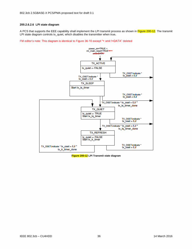
200.2.6.2.6 LPI state diagram
A PCS that supports the EEE capability shall implement the LPI transmit process as shown in Figure 200-12. The transmit LPI state diagram controls tx_quiet, which disables the transmitter when true. FM editor’s note: This diagram is identical to Figure 36-10 except “+ xmit !=DATA” deleted
Figure 200-12 LPI Transmit state diagram

802.3cb 2.5GBASE-X PCS/PMA proposed text for draft 0.1
IEEE 802.3cb – CU4HDD 37 14 March 2016
The timer values for these state diagrams are shown in Table 200-6 for transmit and Table 200-7 for receive.
Table 200-6 Transmitter LPI timing parameters
FM editor’s note – copy table 36-8 as is.
Table 200-7 Receiver LPI timing parameters
FM editor’s note – copy table 36-9 as is.
200.2.6.2.7 LPI status and management
For EEE capability, the PCS indicates to the management system that LPI is currently active in the receive and transmit directions using the status variables shown in Table 36–10.

802.3cb 2.5GBASE-X PCS/PMA proposed text for draft 0.1
IEEE 802.3cb – CU4HDD 38 14 March 2016
200.3 Physical Medium Attachment (PMA) sublayer
200.3.1 Service Interface
The PMA provides a Service Interface to the PCS. These services are described in an abstract manner and do not imply any particular implementation. The PMA Service Interface supports the exchange of code-groups between PCS entities. The PMA converts code-groups into bits and passes these to the PMD, and vice versa. It also generates an additional status indication for use by its client. The following primitives are defined: PMA_UNITDATA.request(tx_code-group<9:0>) PMA_UNITDATA.indication(rx_code-group<9:0>) 200.3.1.1 PMA_UNITDATA.request
This primitive defines the transfer of data (in the form of code-groups) from the PCS to the PMA. PMA_UNITDATA.request is generated by the PCS Transmit process. 200.3.1.1.1 Semantics of the service primitive
PMA_UNITDATA.request(tx_code-group<9:0>) The data conveyed by PMA_UNITDATA.request is the tx_code-group<9:0> parameter defined in 200.2.6.1.3. 200.3.1.1.2 When generated
The PCS continuously sends, at a nominal rate of 312.5 MHz, tx_codegroup<9:0> to the PMA. 200.3.1.1.3 Effect of receipt
Upon receipt of this primitive, the PMA generates a series of ten PMD_UNITDATA.request primitives, requesting transmission of the indicated tx_bit to the PMD. 200.3.1.2 PMA_UNITDATA.indication
This primitive defines the transfer of data (in the form of code-groups) from the PMA to the PCS. PMA_UNITDATA.indication is used by the PCS Synchronization process. 200.3.1.2.1 Semantics of the service primitive
PMA_UNITDATA.indication(rx_code-group<9:0>) The data conveyed by PMA_UNITDATA.indication is the rx_code-group<9:0> parameter defined in 200.2.6.1.3. 200.3.1.2.2 When generated
The PMA continuously sends one rx_code-group<9:0> to the PCS corresponding to the receipt of each code-group aligned set of ten PMD_UNITDATA.indication primitives received from the PMD. The nominal rate of the PMA_UNITDATA.indication primitive is 312.5 MHz, as governed by the recovered bit clock. 200.3.1.2.3 Effect of receipt
The effect of receipt of this primitive by the client is unspecified by the PMA sublayer.

802.3cb 2.5GBASE-X PCS/PMA proposed text for draft 0.1
IEEE 802.3cb – CU4HDD 39 14 March 2016
200.3.2 Functions within the PMA
Figure 200-2 and Figure 200-3 depicts the mapping of the four octet-wide data path of the XGMII to the ten-bit-wide code-groups of the PMA Service Interface, and on to the serial PMD Service Interface. The PMA comprises the PMA Transmit and PMA Receive processes for 2.5GBASE-X. The PMA Transmit process serializes tx_code-groups into tx_bits and passes them to the PMD for transmission on the underlying medium, according to Figure 200-3. Similarly, the PMA Receive process deserializes rx_bits received from the PMD according to Figure 200-3. The PMA continuously conveys ten bit code-groups to the PCS, independent of code-group alignment. After code-group alignment is achieved, based on comma detection, the PCS converts code-groups into XGMII data octets, according to 200.2.6.2.4 and 200.2.6.2.5. The proper alignment of a comma used for code-group synchronization is depicted in Figure 200-3. 200.3.2.1 Data delay
The PMA maps a nonaligned one-bit data path from the PMD to an aligned, ten-bit-wide data path to the PCS, on the receive side. Logically, received bits must be buffered to facilitate proper code-group alignment. These functions necessitate an internal PMA delay of at least ten bit times. In practice, code-group alignment may necessitate even longer delays of the incoming rx_bit stream. 200.3.2.2 PMA transmit function
The PMA Transmit function passes data unaltered (except for serializing) from the PCS directly to the PMD. Upon receipt of a PMA_UNITDATA.request primitive, the PMA Transmit function shall serialize the ten bits of the tx_code-group<9:0> parameter and transmit them to the PMD in the form of ten successive PMD_UNITDATA.request primitives, with tx_code-group<0> transmitted first, and tx_code-group<9> transmitted last. 200.3.2.3 PMA receive function
The PMA Receive function passes data unaltered (except for deserializing and possible code-group slipping upon code-group alignment) from the PMD directly to the PCS. Upon receipt of ten successive PMD_UNITDATA.indication primitives, the PMA shall assemble the ten received rx_bits into a single tenbit value and pass that value to the PCS as the rx_code-group<9:0> parameter of the primitive PMA_UNITDATA.indication, with the first received bit installed in rx_code-group<0> and the last received bit installed in rx_code-group<9>. An exception to this operation is specified in 200.3.2.4. 200.3.2.4 Code-group alignment
In the event the PMA sublayer detects a comma+ within the incoming rx_bit stream, it may realign its current code-group boundary, if necessary, to that of the received comma+ as shown in Figure 36–3. This process is referred to in this document as code-group alignment. During the code-group alignment process, the PMA sublayer may delete or modify up to four, but shall delete or modify no more than four, ten-bit code-groups in order to align the correct receive clock and code-group containing the comma+. This process is referred to as code-group slipping. In addition, the PMA sublayer is permitted to realign the current code-group boundary upon receipt of a comma-pattern.
200.3.3 Loopback mode
Loopback mode shall be provided, as specified in this subclause, by the transmitter and receiver of a device as a test function to the device. When Loopback mode is selected, transmission requests passed to the transmitter are shunted directly to the receiver, overriding any signal detected by the receiver on its attached link. A device is explicitly placed in Loopback mode (i.e., Loopback mode is not the normal mode of operation of a device). The method of implementing Loopback mode is not defined by this standard. NOTE—Loopback mode may be implemented either in the parallel or the serial circuitry of a device. 200.3.3.1 Receiver considerations
Entry into or exit from Loopback mode may result in a temporary loss of synchronization.

802.3cb 2.5GBASE-X PCS/PMA proposed text for draft 0.1
IEEE 802.3cb – CU4HDD 40 14 March 2016
200.3.3.2 Transmitter considerations
While in Loopback mode, the transmitter output is not defined. 200.3.4 Test functions
A limited set of test functions may be provided as an implementation option for testing of the transmitter function or for testing of an attached receiver. Some test functions that are not defined by this standard may be provided by certain implementations. Compliance with the standard is not affected by the provision or exclusion of such functions by an implementation. Random jitter test patterns for 2.5GBASE-X are specified in Annex 200A. A typical test function is the ability to transmit invalid code-groups within an otherwise valid PHY bit stream. Certain invalid PHY bit streams may cause a receiver to lose word and/or bit synchronization. See ANSI X3.230-1994 [B21] (FC-PH), subclause 5.4, for a more detailed discussion of receiver and transmitter behavior under various test conditions. 200.4 Compatibility considerations
There is no requirement for a compliant device to implement or expose any of the interfaces specified for the PCS or PMA. Implementations of a XGMII shall comply with the requirements as specified in Clause 46. 200.5 Delay constraints
Predictable operation of the MAC Control PAUSE operation (Clause 31, Annex 31B) demands that there be an upper bound on the propagation delays through the network. This implies that MAC, MAC Control sublayer, and PHY implementers must conform to certain delay maxima, and that network planners and administrators conform to constraints regarding the cable topology and concatenation of devices. The sum of transmit and receive delay contributed by the 2.5GBASE-X PCS and PMA shall be no more than TBD BT. The reference point for all MDI measurements is the 50% point of the mid-cell transition corresponding to the reference bit, as measured at the MDI. 200.6 Environmental specifications
Editor’s Note: Need input on whether this is adequate
All equipment subject to this clause shall conform to the requirements of 71.8. 200.7 Protocol implementation conformance statement (PICS) proforma for Clause 200, Physical Coding
Sublayer (PCS) and Physical Medium Attachment (PMA) sublayer, type 2.5GBASE-X
Editor’s Note: To be inserted later by PICS editor after text stabilizes

802.3cb 2.5GBASE-X PCS/PMA proposed text for draft 0.1
IEEE 802.3cb – CU4HDD 41 14 March 2016
Annex 200A (informative)
Jitter test patterns
This annex defines test patterns for 2.5GBASE-X PMDs. The patterns described in Annex 36A can be used for 2.5GBASE-X except the nominal bit rate is 2.5 times faster and any references to the GMII applies to the XGMII.
Annex 200B (informative)
Compatibility of 2.5GBASE-X PCS/PMA with 1000BASE-X PCS/PMA running 2.5 times faster
This annex discusses the restrictions when operating 2.5GBASE-X PCS/PMA to a 1000BASE-X PCS/PMA link partner running 2.5 times faster. Compatibility of the PMD is outside the scope of this annex. In this annex when 1000BASE-X PCS/PMA is referred to, the 2.5 times speed up is implied. The 2.5GBASE-X PCS/PMA is specified to be compatible with a link partner running 1000BASE-X PCS/PMA running 2.5 times faster as shown in Figure 200B-1 with some restrictions.
1000 Mb/s
MAC
2.5x faster
GMII1000BASE-X
PHY
2.5x faster
10 Gb/s
MAC
4 x slower
XGMII2.5GBASE-X
PHY
(compliant)
Figure 200B-1 2.5X speed 1000BASE-X to 2.5GBASE-X Link
2.5GBASE-X is defined to operate only in full duplex. Hence the 1000BASE-X PCS can only operate in full duplex. If the half duplex carrier extend or carrier extend with errors are sent by the 1000BASE-X PCS, the 2.5GBASE-X PCS will convert it to receive errors. Note that a /T/R/ or a /T/R/R/ at the end of packet will be correctly converted as idles. The 2.5GBASE-X PCS does not support clause 37 Auto-Negotiation. Hence, the 1000BASE-X PCS is expected to have its clause 37 Auto-Negotiation functionality disabled so that the /C/ ordered_set will not be transmitted. If a 2.5GBASE-X PCS receives /C/ ordered_set then undefined behavior may occur. Since the 2.5GBASE-X PCS is attached to a MAC that can send out sequence ordered_set (/Q/), a compliant 1000BASE-X PCS will interpret each /Q/ ordered_set as four /I/ ordered set. Unlike /I/, /LI/, and /C/ ordered_sets, there is no concept of correcting vs preserving the running disparity when /Q/ ordered_sets are generated. Unlike the GMII, there is no false carrier defined in the XGMII. The 2.5GBASE-X PCS Receive process can detect false carrier, but these will be converted to receive error by the PCS Word Decode process. It is permissible for a compliant 1000BASE-X PCS transmit process to truncated the first byte of preamble in order to align the start of packet on the EVEN boundary. The implication of this is the 2.5Gb/s MAC has to be able to accept a seven byte preamble on the XGMII. Since the start of packet has to align to lane 0 of the XGMII the 2.5Gb/s MAC may delete idle bytes in order to do the alignment. The 1G MAC running 2.5 time faster has to be able to handle IPG shrinkage.