proposed tests with beam
DESCRIPTION
Proposed tests with beam. Massimo Giovannozzi Acknowledgements: G. Arduini, B. Goddard, M. Lamont, S. Redaelli , N. Sammut, J. Uythoven , J. Wenninger. Evolution of sector test proposals. 2006: Detailed analysis presented at the Chamonix Workshop. 2007: - PowerPoint PPT PresentationTRANSCRIPT
March 4th 2008 M. Giovannozzi - Extended LTC 1
Proposed tests with beam
Massimo Giovannozzi
Acknowledgements: G. Arduini, B. Goddard, M. Lamont, S. Redaelli, N. Sammut, J. Uythoven, J. Wenninger.
March 4th 2008 M. Giovannozzi - Extended LTC 2
Evolution of sector test proposals• 2006:
– Detailed analysis presented at the Chamonix Workshop.
• 2007:
– Sector test without triplets and D1 in IP8 (right). Option quickly discarded.
– LHC MAC presentation (M. Lamont).
• 2008:
– Extensive analysis of various phases of LHC commissioning performed by LHCCWG: sector test would allow applying procedures that will be needed later.
– Beam 1 is also considered in the general scheme of a sector test.
March 4th 2008 M. Giovannozzi - Extended LTC 3
Brief summary of the items/systems to consider
• Injection and threading
• Instrumentation
• Optics measurements
• Aperture checks
• Effect of magnetic cycle
• Field quality checks
• Quench limits and BLM response
• Others
March 4th 2008 M. Giovannozzi - Extended LTC 4
Boundary conditions - I• LSS and arc(s) should not be irradiated• LHCb should also be preserved
• This can be achieved by:– Minimising losses– Optimising/minimising the amount of beam used for the tests.
• The beam parameters are– Pilot beam is the preferred choice: 5 x 10⁹ p+, below quench
limit, about x100 below damage threshold– Some tests with 1-3 x 10¹⁰ or up to 1 x 10¹¹ p+ in one bunch– Beam emittance: 1 m < n < 3.5 m (lower emittances might be
problematic for machine protection…)– Momentum spread: nominal, but smaller might be useful…
See presentation by See presentation by H. Vincke H. Vincke
March 4th 2008 M. Giovannozzi - Extended LTC 5
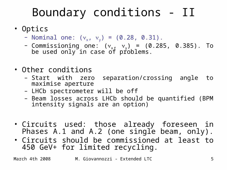
Boundary conditions - II• Optics
– Nominal one: (x, y) = (0.28, 0.31).– Commissioning one: (x, y) = (0.285, 0.385). To be used only in
case of problems.
• Other conditions– Start with zero separation/crossing angle to maximise aperture– LHCb spectrometer will be off – Beam losses across LHCb should be quantified (BPM intensity
signals are an option)
• Circuits used: those already foreseen in Phases A.1 and A.2 (one single beam, only).
• Circuits should be commissioned at least to 450 GeV+ for limited recycling.
March 4th 2008 M. Giovannozzi - Extended LTC 6
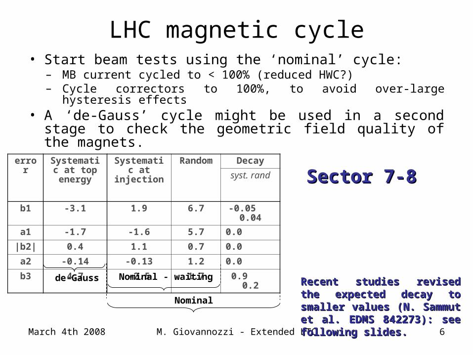
LHC magnetic cycle• Start beam tests using the ‘nominal’ cycle:
– MB current cycled to < 100% (reduced HWC?)– Cycle correctors to 100%, to avoid over-large hysteresis effects
• A ‘de-Gauss’ cycle might be used in a second stage to check the geometric field quality of the magnets.
error Systematic at top
energy
Systematic at injection
Random Decay
syst. rand
b1 -3.1 1.9 6.7 -0.05 0.04
a1 -1.7 -1.6 5.7 0.0
|b2| 0.4 1.1 0.7 0.0
a2 -0.14 -0.13 1.2 0.0
b3 4.7 -2.5 1.7 0.9 0.2
de-Gauss Nominal - waiting
Nominal
Sector 7-8Sector 7-8
Recent studies revised the Recent studies revised the expected decay to smaller expected decay to smaller values (N. Sammut et al. EDMS values (N. Sammut et al. EDMS 842273): see following slides.842273): see following slides.
March 4th 2008 M. Giovannozzi - Extended LTC 7
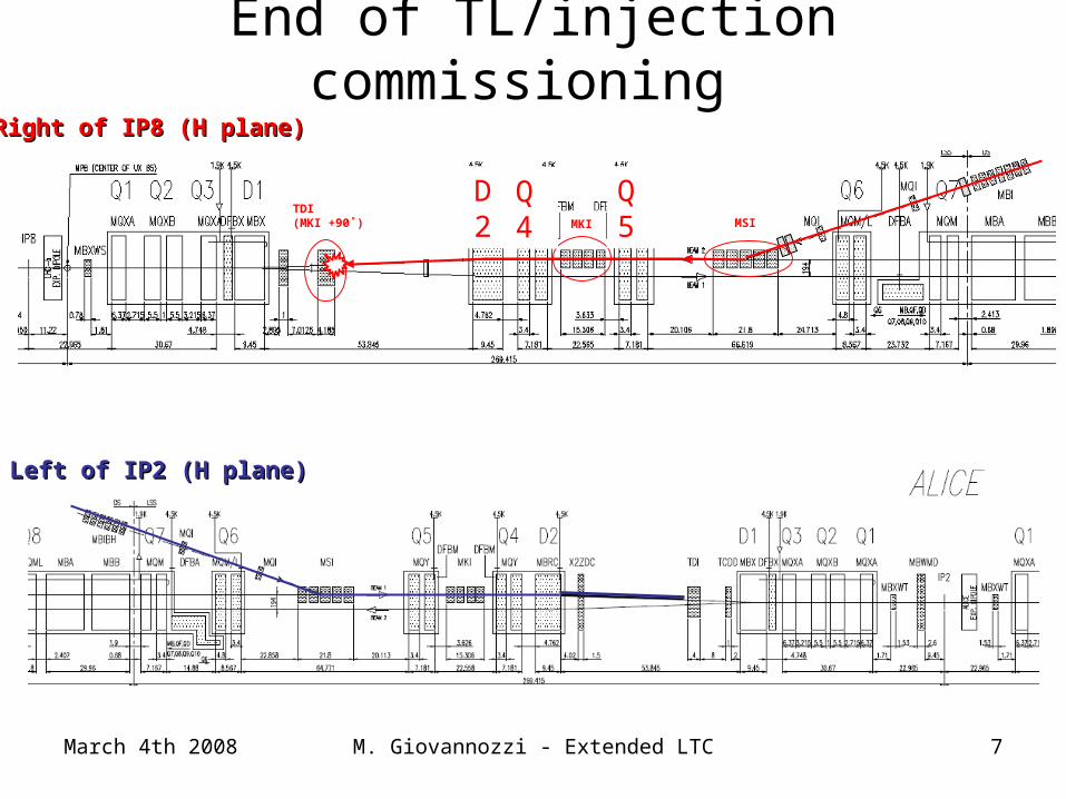
Right of IP8 (H plane)Right of IP8 (H plane)
TDI(MKI +90˚) MKI MSI
Q5
Q4
D2
End of TL/injection commissioning
Left of IP2 (H plane)Left of IP2 (H plane)
March 4th 2008 M. Giovannozzi - Extended LTC 8
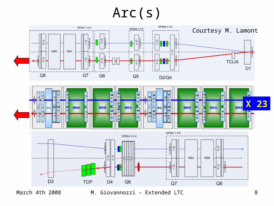
Arc(s)
X 23
Courtesy M. Lamont
March 4th 2008 M. Giovannozzi - Extended LTC 9
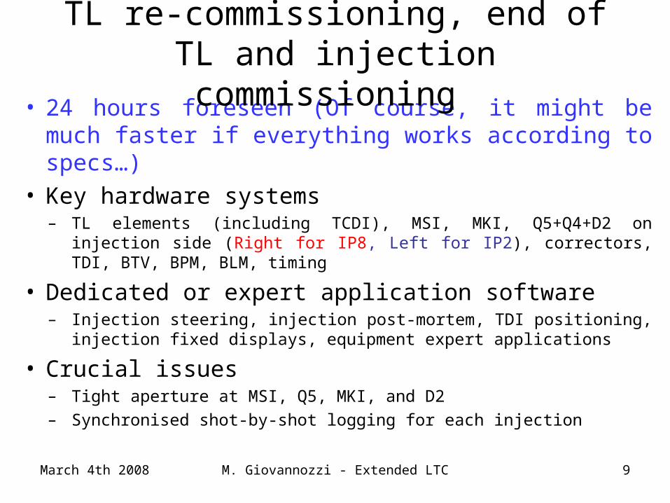
• 24 hours foreseen (Of course, it might be much faster if everything works according to specs…)
• Key hardware systems– TL elements (including TCDI), MSI, MKI, Q5+Q4+D2 on injection side
(Right for IP8, Left for IP2), correctors, TDI, BTV, BPM, BLM, timing
• Dedicated or expert application software– Injection steering, injection post-mortem, TDI positioning, injection
fixed displays, equipment expert applications
• Crucial issues– Tight aperture at MSI, Q5, MKI, and D2 – Synchronised shot-by-shot logging for each injection
TL re-commissioning, end of TL and injection commissioning
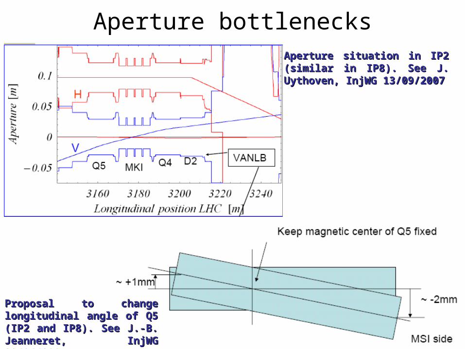
Aperture bottlenecks
March 4th 2008 M. Giovannozzi - Extended LTC 10
Aperture situation in IP2 (similar Aperture situation in IP2 (similar in IP8). See J. Uythoven, InjWG in IP8). See J. Uythoven, InjWG 13/09/200713/09/2007
Proposal to change Proposal to change longitudinal angle of Q5 (IP2 longitudinal angle of Q5 (IP2 and IP8). See J.-B. Jeanneret, and IP8). See J.-B. Jeanneret, InjWG 29/06/2007InjWG 29/06/2007
March 4th 2008 M. Giovannozzi - Extended LTC 11
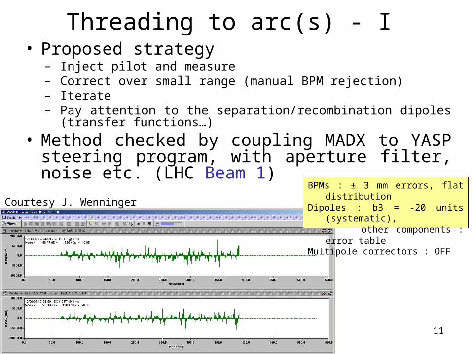
Threading to arc(s) - I • Proposed strategy
– Inject pilot and measure– Correct over small range (manual BPM rejection)– Iterate– Pay attention to the separation/recombination dipoles (transfer
functions…)
• Method checked by coupling MADX to YASP steering program, with aperture filter, noise etc. (LHC Beam 1)
Courtesy J. Wenninger
BPMs : ± 3 mm errors, flat distribution Dipoles : b3 = -20 units (systematic),
other components : error tableMultipole correctors : OFF
March 4th 2008 M. Giovannozzi - Extended LTC 12
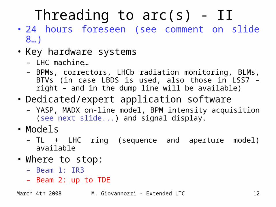
• 24 hours foreseen (see comment on slide 8…)• Key hardware systems
– LHC machine… – BPMs, correctors, LHCb radiation monitoring, BLMs, BTVs
(in case LBDS is used, also those in LSS7 – right – and in the dump line will be available)
• Dedicated/expert application software– YASP, MADX on-line model, BPM intensity acquisition
(see next slide...) and signal display.
• Models– TL + LHC ring (sequence and aperture model) available
• Where to stop:– Beam 1: IR3– Beam 2: up to TDE
Threading to arc(s) - II
March 4th 2008 M. Giovannozzi - Extended LTC 13
• Monitoring beam intensity during the sector test phases will be crucial for many reasons, e.g.:– Controlling beam losses and correlate them with
activation– Aperture measurements (see next slides)– Quench behaviour tests (see Ralph’s presentation)
• How to get the intensity information: – BPM in intensity mode: this prevents the signal from the
other beam (not a problem for the sector test...). Is this mode operational?
– Temporary BCTs (not necessary if dump line is used)?
• The selected beam intensity should be high enough to allow for losses (in early stages of the tests) without losing BPM triggering.
Threading to arc(s) - III
March 4th 2008 M. Giovannozzi - Extended LTC 14-4
-3
-2
-1
0
1
2
1500 1750 2000 2250 2500 2750 3000 3250 3500 3750 4000 4250 4500 4750 5000 5250 5500 5750 6000S [m]
D [
m]
DX
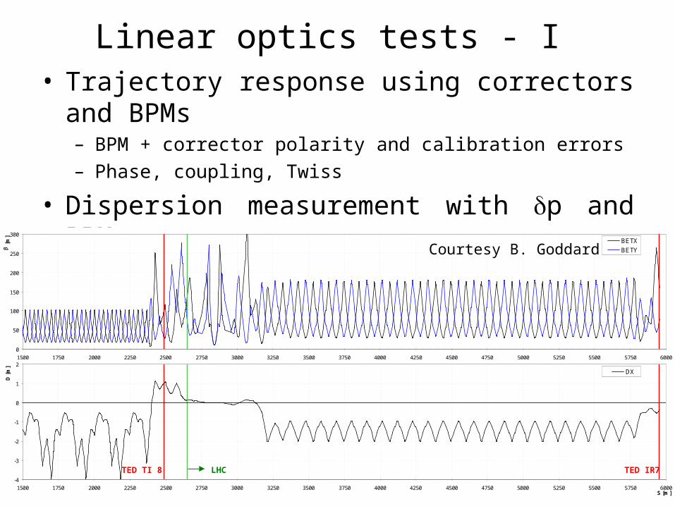
Linear optics tests - I • Trajectory response using correctors and BPMs
– BPM + corrector polarity and calibration errors– Phase, coupling, Twiss
• Dispersion measurement with p and BPMs• Betatron matching measurement with BTVs
TED TI 8 TED IR7LHC
0
50
100
150
200
250
300
1500 1750 2000 2250 2500 2750 3000 3250 3500 3750 4000 4250 4500 4750 5000 5250 5500 5750 6000S [m]
b [
m]
BETX
BETYCourtesy B. Goddard
March 4th 2008 M. Giovannozzi - Extended LTC 15
• 12 hours foreseen– 1-2 x 10¹⁰ p+ for improved BPM and BTV response– Semi-automated tests. Efficient tool for quick off-line data
analysis
• Key hardware systems– BPMs, correctors, BTVs
• Dedicated/expert application software– On-line re-matching and analysis tools might not be needed– In general tools were developed (TI8/2 tests in 2004/7) and are
under development (e.g., MADX on-line model).
Linear optics tests - II
March 4th 2008 M. Giovannozzi - Extended LTC 16
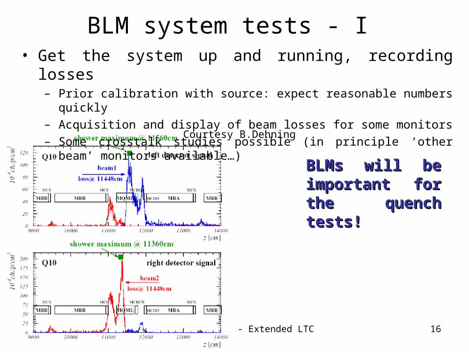
• Get the system up and running, recording losses– Prior calibration with source: expect reasonable numbers quickly
– Acquisition and display of beam losses for some monitors
– Some crosstalk studies possible (in principle ‘other beam’ monitors available…)
BLM system tests - I
Courtesy B.Dehning
BLMs will be BLMs will be important for the important for the quench tests!quench tests!
March 4th 2008 M. Giovannozzi - Extended LTC 17
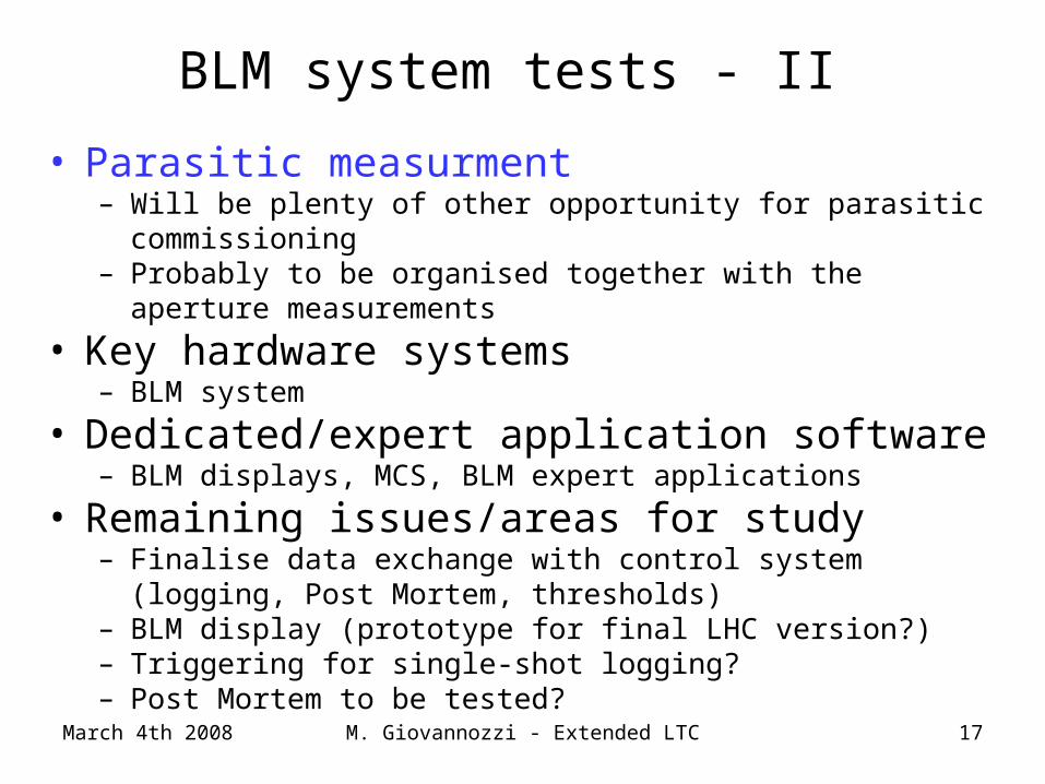
BLM system tests - II
• Parasitic measurment– Will be plenty of other opportunity for parasitic commissioning– Probably to be organised together with the aperture measurements
• Key hardware systems– BLM system
• Dedicated/expert application software– BLM displays, MCS, BLM expert applications
• Remaining issues/areas for study– Finalise data exchange with control system (logging, Post Mortem,
thresholds) – BLM display (prototype for final LHC version?)– Triggering for single-shot logging?– Post Mortem to be tested?
March 4th 2008 M. Giovannozzi - Extended LTC 18
-20
-15
-10
-5
0
5
10
15
20
1500 1750 2000 2250 2500 2750 3000 3250 3500 3750 4000 4250 4500 4750 5000 5250 5500 5750 6000S [m]
Ns X aperture
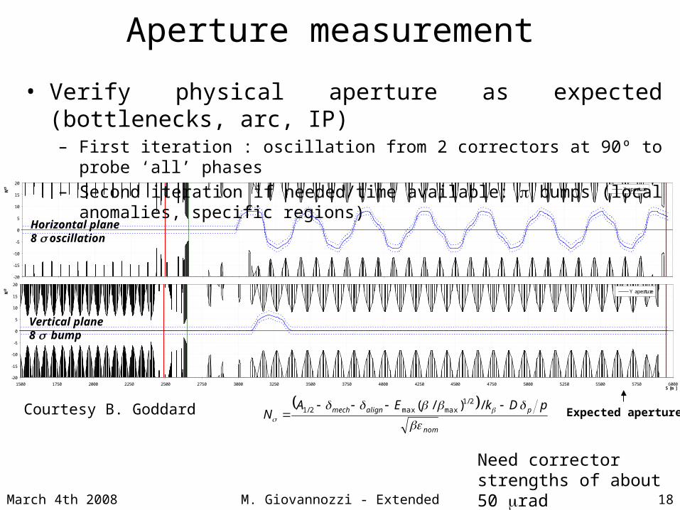
Aperture measurement
• Verify physical aperture as expected (bottlenecks, arc, IP)– First iteration : oscillation from 2 correctors at 90º to probe ‘all’ phases
– Second iteration if needed/time available: bumps (local anomalies, specific regions)
Expected aperture
Horizontal plane8 s oscillation
-20
-15
-10
-5
0
5
10
15
20
1500 1750 2000 2250 2500 2750 3000 3250 3500 3750 4000 4250 4500 4750 5000 5250 5500 5750 6000S [m]
Ns Y aperture
nom
palignmech pDkEAN
bbb b
s
/)/( 2/1maxmax2/1
Vertical plane8 sbump
Need corrector strengths of about 50 rad
Courtesy B. Goddard
-0.03
-0.02
-0.01
0
0.01
0.02
0.03
1500 1750 2000 2250 2500 2750 3000 3250 3500 3750 4000 4250 4500 4750 5000 5250 5500 5750 6000
S [m]
x [m
]
X
March 4th 2008 M. Giovannozzi - Extended LTC 19
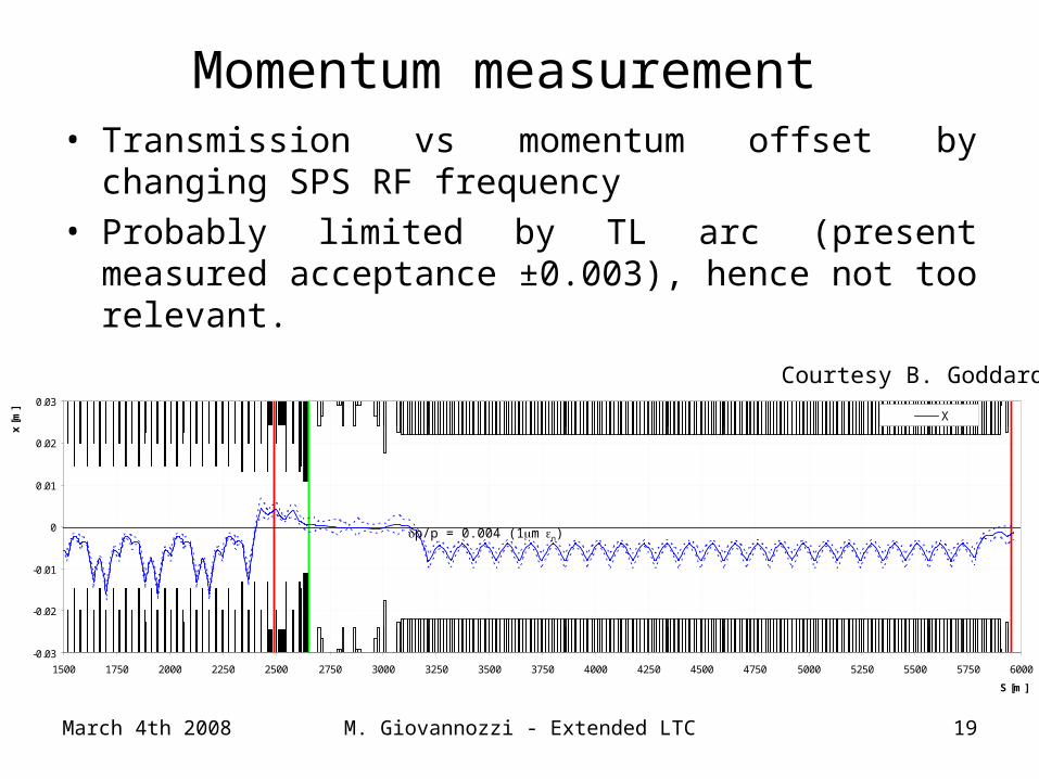
Momentum measurement • Transmission vs momentum offset by changing SPS RF
frequency• Probably limited by TL arc (present measured
acceptance ±0.003), hence not too relevant.
p/p = 0.004 (1mn)
Courtesy B. Goddard
March 4th 2008 M. Giovannozzi - Extended LTC 20
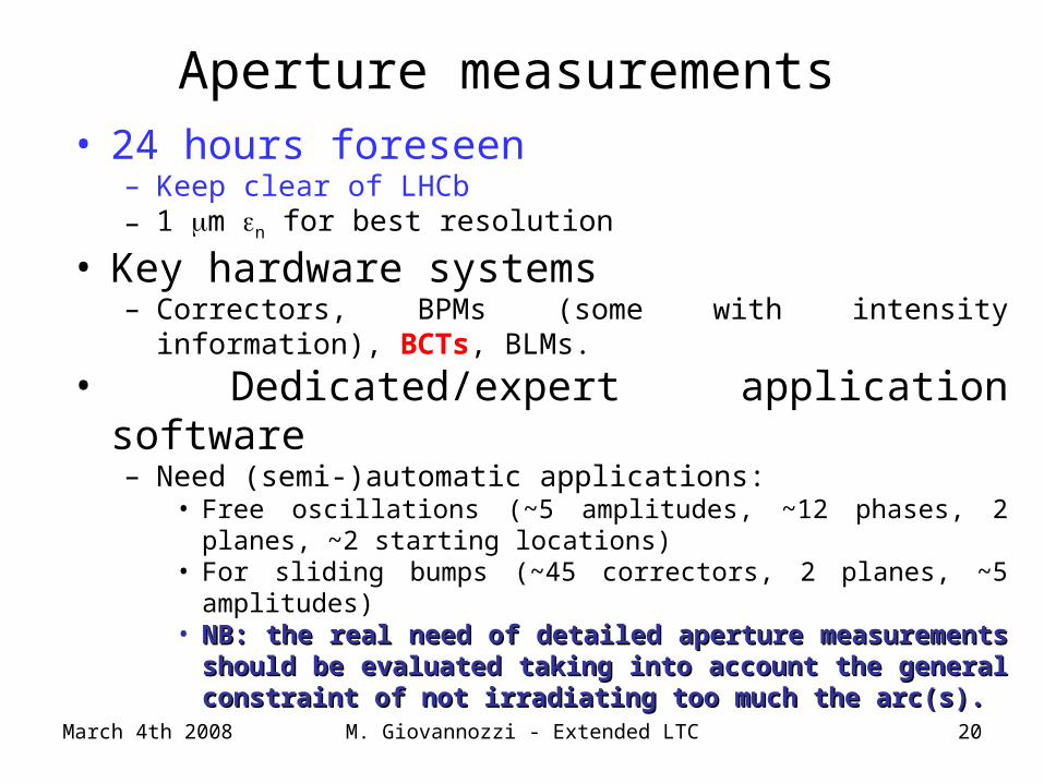
Aperture measurements • 24 hours foreseen
– Keep clear of LHCb– 1 m n for best resolution
• Key hardware systems– Correctors, BPMs (some with intensity information), BCTs, BLMs.
• Dedicated/expert application software– Need (semi-)automatic applications:
• Free oscillations (~5 amplitudes, ~12 phases, 2 planes, ~2 starting locations)
• For sliding bumps (~45 correctors, 2 planes, ~5 amplitudes)• NB: the real need of detailed aperture measurements should be NB: the real need of detailed aperture measurements should be
evaluated taking into account the general constraint of not evaluated taking into account the general constraint of not irradiating too much the arc(s).irradiating too much the arc(s).
March 4th 2008 M. Giovannozzi - Extended LTC 21
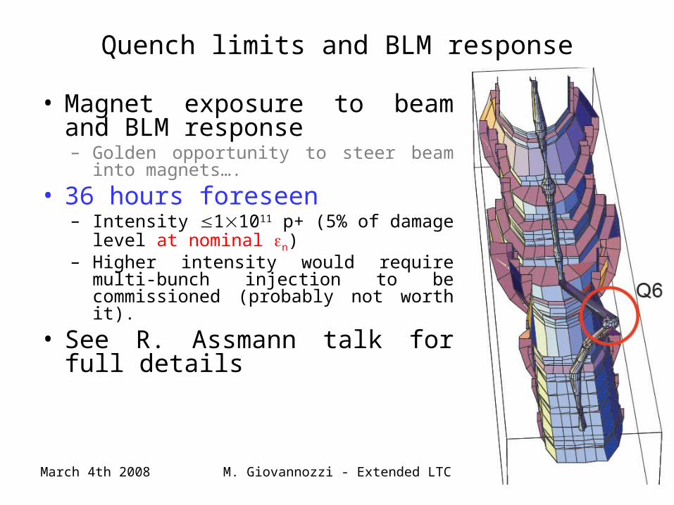
Quench limits and BLM response
• Magnet exposure to beam and BLM response– Golden opportunity to steer beam into
magnets….
• 36 hours foreseen– Intensity 11011 p+ (5% of damage level
at nominal n)– Higher intensity would require multi-bunch
injection to be commissioned (probably not worth it).
• See R. Assmann talk for full details
March 4th 2008 M. Giovannozzi - Extended LTC 22
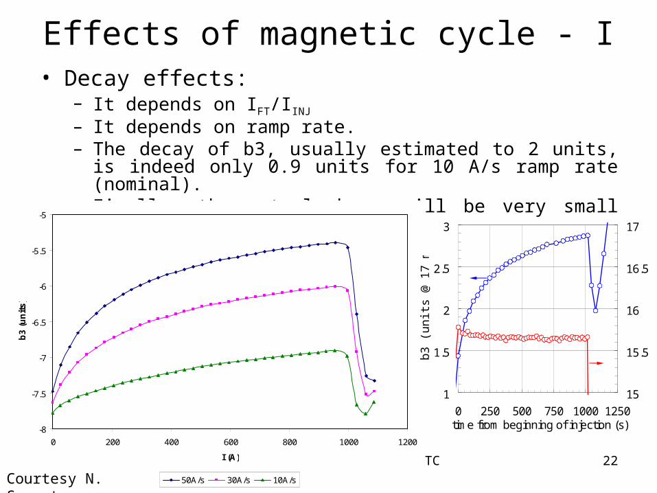
Effects of magnetic cycle - I • Decay effects:
– It depends on IFT/IINJ
– It depends on ramp rate. – The decay of b3, usually estimated to 2 units, is indeed only 0.9
units for 10 A/s ramp rate (nominal).– Finally, the actual decay will be very small for IFT < INOM
-8
-7.5
-7
-6.5
-6
-5.5
-5
0 200 400 600 800 1000 1200
I (A)
b3 (
un
its)
50A/s 30A/s 10A/sCourtesy N. Sammut
1
1.5
2
2.5
3
0 250 500 750 1000 1250time from beginning of injection (s)
b3 (
units
@ 1
7 m
m)
15
15.5
16
16.5
17
March 4th 2008 M. Giovannozzi - Extended LTC 23
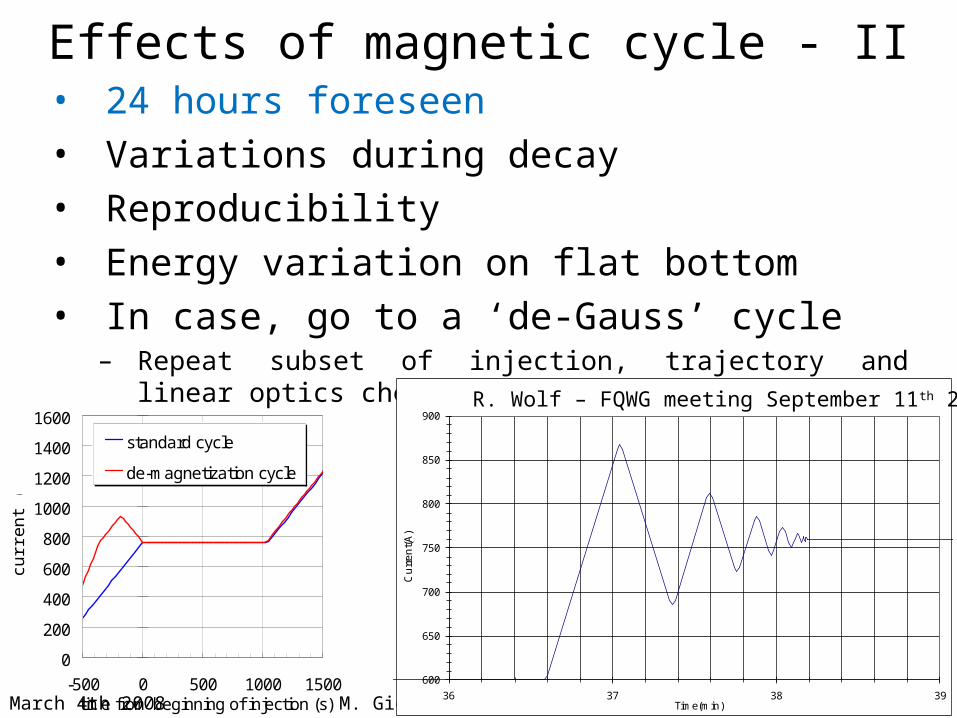
Effects of magnetic cycle - II• 24 hours foreseen• Variations during decay• Reproducibility• Energy variation on flat bottom• In case, go to a ‘de-Gauss’ cycle
– Repeat subset of injection, trajectory and linear optics checks
0
200
400
600
800
1000
1200
1400
1600
-500 0 500 1000 1500time from beginning of injection (s)
curr
ent
(A)
standard cycle
de-magnetization cycle
600
650
700
750
800
850
900
36 37 38 39
Cu
rre
nt(
A)
Time(min)
LHC MB set up, reference with demagnetization cycleR. Wolf – FQWG meeting September 11th 2007
March 4th 2008 M. Giovannozzi - Extended LTC 24
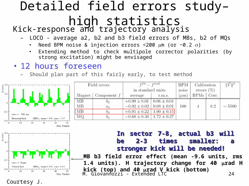
Detailed field errors study– high statisticsKick-response and trajectory analysis
– LOCO - average a2, b2 and b3 field errors of MBs, b2 of MQs• Need BPM noise & injection errors <200 m (or ~0.2 s) • Extending method to check multipole corrector polarities (by strong excitation)
might be envisaged
• 12 hours foreseen– Should plan part of this fairly early, to test method
Courtesy J. Wenninger
MB b3 field error effect (mean -9.6 units, rms 1.4 units). H trajectory change for 40 rad H kick (top) and 40 rad V kick (bottom)
In sector 7-8, actual b3 will be 2-3 times In sector 7-8, actual b3 will be 2-3 times smaller: a stronger kick will be needed!smaller: a stronger kick will be needed!
March 4th 2008 M. Giovannozzi - Extended LTC 25
Other studies• Transfer line collimation studies• Injection protection studies• Impact of MKI wave form on injection
performance• Separation and crossing angle bumps (these are
not needed for Phase A)– Injecting onto vertical separation bump– Bump closure, induced dispersion, aperture
March 4th 2008 M. Giovannozzi - Extended LTC 26
-20
-15
-10
-5
0
5
10
15
20
2200 2300 2400 2500 2600 2700 2800 2900 3000 3100S [m]
Ns Y aperture
-0.01
-0.008
-0.006
-0.004
-0.002
0
0.002
0.004
0.006
0.008
0.01
2400 2500 2600 2700 2800 2900 3000 3100S [m]
x/y
[m]
XY
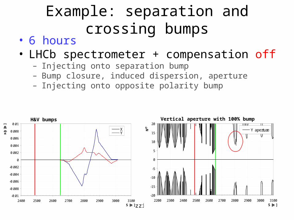
Example: separation and crossing bumps
• 6 hours• LHCb spectrometer + compensation off
– Injecting onto separation bump– Bump closure, induced dispersion, aperture– Injecting onto opposite polarity bump
Vertical aperture with 100% bumpH&V bumps
March 4th 2008 M. Giovannozzi - Extended LTC 27
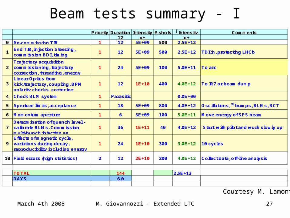
Beam tests summary - IPriority Duration Intensity # shots Intensity Comments
12 p+ p+0 Re-commission TI8 1 12 5E+09 500 2.5E+12
1End TI8, Injection Steering, commission BDI, timing
1 12 5E+09 500 2.5E+12 TDI in, protecting LHCb
2Trajectory acquisition commissioning, trajectory correction, threading, energy matching
1 24 5E+09 100 5.0E+11 To arc
3Linear Optics from kick/trajectory, coupling, BPM polarity checks, corrector
1 12 1E+10 400 4.0E+12 To IR7 or beam dump
4 Check BLM system 1 Parasitic 0.0E+00
5 Aperture limits, acceptance 1 18 5E+09 800 4.0E+12 Oscillations, bumps, BLMs, BCT
6 Momentum aperture 1 6 5E+09 100 5.0E+11 Move energy of SPS beam
7Determination of quench level - calibrate BLMs. Commission multi-bunch injection as
1 36 1E+11 40 4.0E+12 Start with pilot and work slowly up
9Effects of magnetic cycle, variations during decay, reproducibility including energy
1 24 1E+10 300 3.0E+12 10 cycles
10 Field errors (high statistics) 2 12 2E+10 200 4.0E+12 Collect data, off-line analysis
TOTAL 144 2.5E+13DAYS 6.0
Courtesy M. Lamont
March 4th 2008 M. Giovannozzi - Extended LTC 28
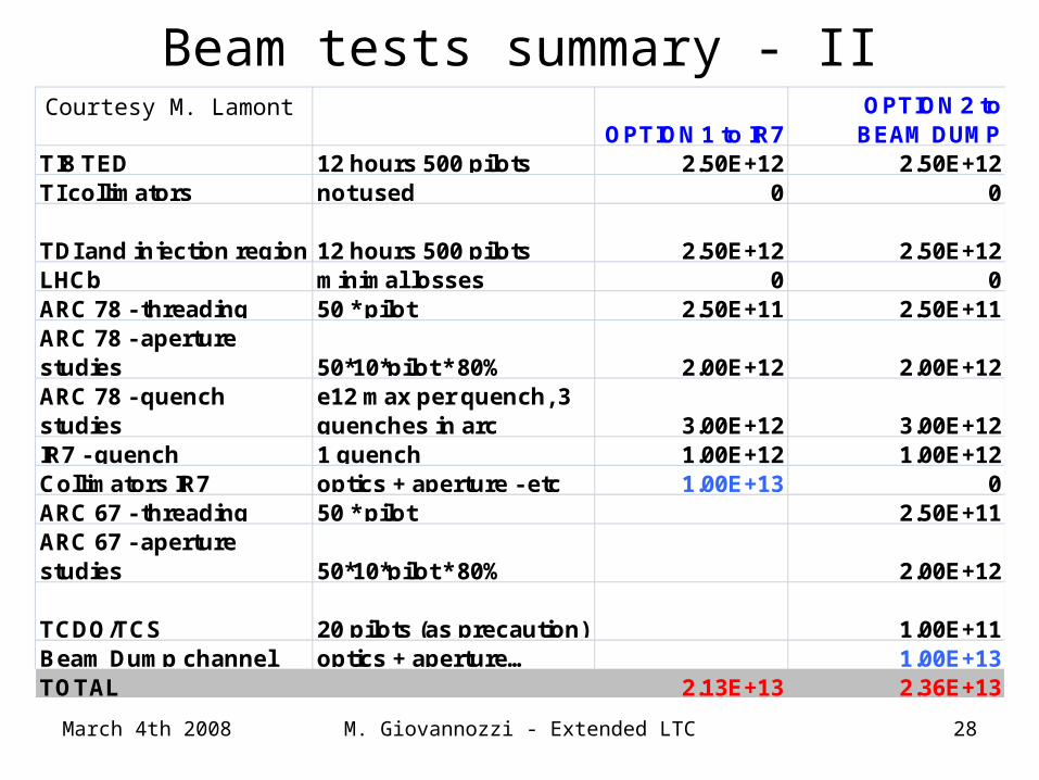
Beam tests summary - II
OPTION 1 to IR7OPTION 2 to
BEAM DUMPTI8 TED 12 hours 500 pilots 2.50E+12 2.50E+12TI collimators not used 0 0
TDI and injection region 12 hours 500 pilots 2.50E+12 2.50E+12LHCb minimal losses 0 0ARC 78 - threading 50 * pilot 2.50E+11 2.50E+11ARC 78 - aperture studies 50*10*pilot * 80% 2.00E+12 2.00E+12ARC 78 - quench studies
e12 max per quench, 3 quenches in arc 3.00E+12 3.00E+12
IR7 - quench 1 quench 1.00E+12 1.00E+12Collimators IR7 optics + aperture - etc 1.00E+13 0ARC 67 - threading 50 * pilot 2.50E+11ARC 67 - aperture studies 50*10*pilot * 80% 2.00E+12
TCDQ/TCS 20 pilots (as precaution) 1.00E+11Beam Dump channel optics + aperture… 1.00E+13TOTAL 2.13E+13 2.36E+13
Courtesy M. Lamont
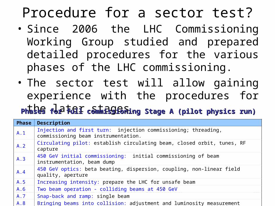
Procedure for a sector test?• Since 2006 the LHC Commissioning Working
Group studied and prepared detailed procedures for the various phases of the LHC commissioning.
• The sector test will allow gaining experience with the procedures for the later stages.
March 4th 2008 M. Giovannozzi - Extended LTC 29
Phase Description
A.1 Injection and first turn: injection commissioning; threading, commissioning beam instrumentation.
A.2 Circulating pilot: establish circulating beam, closed orbit, tunes, RF capture
A.3 450 GeV initial commissioning: initial commissioning of beam instrumentation, beam dump
A.4 450 GeV optics: beta beating, dispersion, coupling, non-linear field quality, aperture
A.5 Increasing intensity: prepare the LHC for unsafe beam
A.6 Two beam operation - colliding beams at 450 GeV
A.7 Snap-back and ramp: single beam
A.8 Bringing beams into collision: adjustment and luminosity measurement
A.9 7 TeV optics: beta beating, dispersion, coupling, non-linear field quality, aperture
A.10 Squeeze: commissioning the betatron squeeze in all IP's
A.11 Physics runs: physics with partially squeezed beams, no crossing in IP1 and IP5
Phases for full commissioning Stage A (pilot physics run)Phases for full commissioning Stage A (pilot physics run)
March 4th 2008
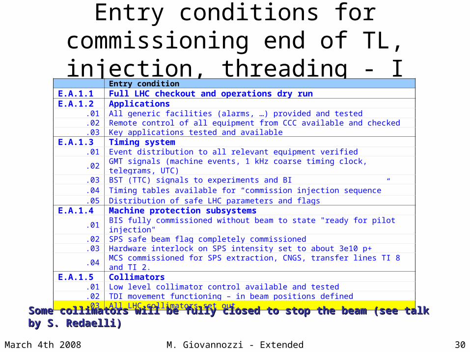
Entry conditions for commissioning end of TL, injection, threading - I
Entry conditionE.A.1.1 Full LHC checkout and operations dry runE.A.1.2 Applications
.01 All generic facilities (alarms, …) provided and tested
.02 Remote control of all equipment from CCC available and checked
.03 Key applications tested and availableE.A.1.3 Timing system
.01 Event distribution to all relevant equipment verified
.02 GMT signals (machine events, 1 kHz coarse timing clock, telegrams, UTC)
.03 BST (TTC) signals to experiments and BI
.04 Timing tables available for “commission injection sequence”
.05 Distribution of safe LHC parameters and flagsE.A.1.4 Machine protection subsystems
.01 BIS fully commissioned without beam to state "ready for pilot injection"
.02 SPS safe beam flag completely commissioned
.03 Hardware interlock on SPS intensity set to about 3e10 p+
.04 MCS commissioned for SPS extraction, CNGS, transfer lines TI 8 and TI 2. E.A.1.5 Collimators
.01 Low level collimator control available and tested
.02 TDI movement functioning – in beam positions defined
.03 All LHC collimators set out.
Some collimators will be fully closed to stop the beam (see talk by S. Redaelli)Some collimators will be fully closed to stop the beam (see talk by S. Redaelli)
30M. Giovannozzi - Extended LTC
March 4th 2008
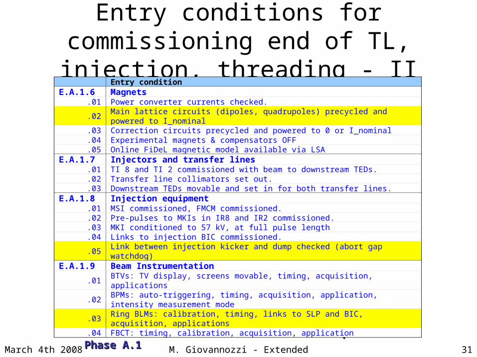
Entry conditions for commissioning end of TL, injection, threading - II
Partial hardware commissioning and unavailability of some Partial hardware commissioning and unavailability of some sectors (LBDS not usable) will relax some constraints with sectors (LBDS not usable) will relax some constraints with respect to Phase A.1respect to Phase A.1
Entry conditionE.A.1.6 Magnets
.01 Power converter currents checked.
.02 Main lattice circuits (dipoles, quadrupoles) precycled and powered to I_nominal
.03 Correction circuits precycled and powered to 0 or I_nominal
.04 Experimental magnets & compensators OFF
.05 Online FiDeL magnetic model available via LSAE.A.1.7 Injectors and transfer lines
.01 TI 8 and TI 2 commissioned with beam to downstream TEDs.
.02 Transfer line collimators set out.
.03 Downstream TEDs movable and set in for both transfer lines. E.A.1.8 Injection equipment
.01 MSI commissioned, FMCM commissioned.
.02 Pre-pulses to MKIs in IR8 and IR2 commissioned.
.03 MKI conditioned to 57 kV, at full pulse length
.04 Links to injection BIC commissioned.
.05 Link between injection kicker and dump checked (abort gap watchdog) E.A.1.9 Beam Instrumentation
.01 BTVs: TV display, screens movable, timing, acquisition, applications
.02 BPMs: auto-triggering, timing, acquisition, application, intensity measurement mode
.03 Ring BLMs: calibration, timing, links to SLP and BIC, acquisition, applications
.04 FBCT: timing, calibration, acquisition, application
31M. Giovannozzi - Extended LTC
March 4th 2008
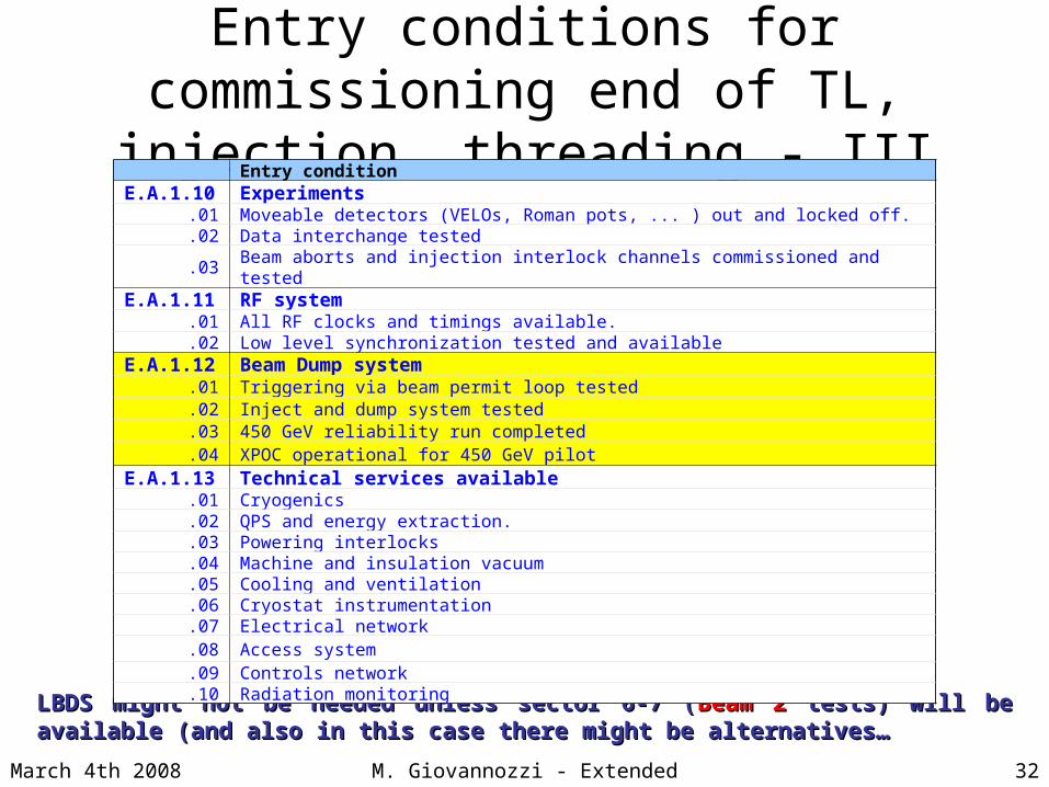
Entry conditions for commissioning end of TL, injection, threading - III
LBDS might not be needed unless sector 6-7 (LBDS might not be needed unless sector 6-7 (Beam 2Beam 2 tests) will be available (and also in tests) will be available (and also in this case there might be alternatives…this case there might be alternatives…
Entry conditionE.A.1.10 Experiments
.01 Moveable detectors (VELOs, Roman pots, ... ) out and locked off.
.02 Data interchange tested
.03 Beam aborts and injection interlock channels commissioned and testedE.A.1.11 RF system
.01 All RF clocks and timings available.
.02 Low level synchronization tested and availableE.A.1.12 Beam Dump system
.01 Triggering via beam permit loop tested
.02 Inject and dump system tested
.03 450 GeV reliability run completed
.04 XPOC operational for 450 GeV pilotE.A.1.13 Technical services available
.01 Cryogenics
.02 QPS and energy extraction.
.03 Powering interlocks
.04 Machine and insulation vacuum
.05 Cooling and ventilation
.06 Cryostat instrumentation
.07 Electrical network
.08 Access system
.09 Controls network
.10 Radiation monitoring
32M. Giovannozzi - Extended LTC
March 4th 2008
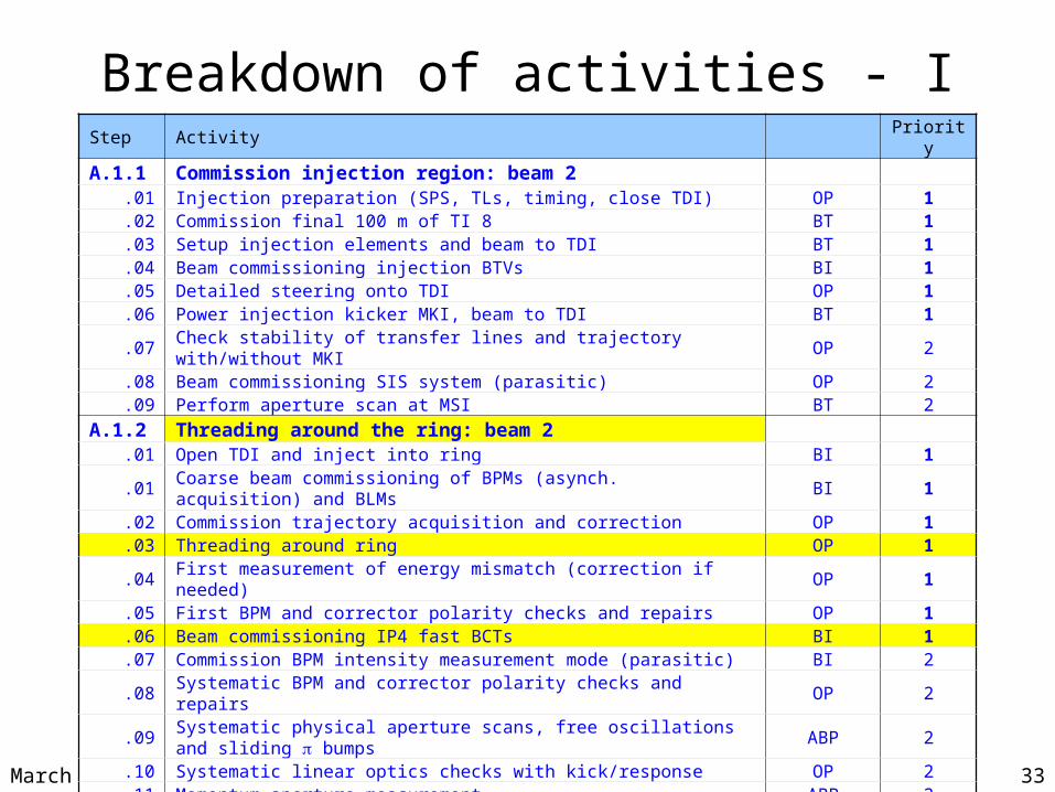
Breakdown of activities - I
33M. Giovannozzi - Extended LTC
Step Activity Priority
A.1.1 Commission injection region: beam 2.01 Injection preparation (SPS, TLs, timing, close TDI) OP 1.02 Commission final 100 m of TI 8 BT 1.03 Setup injection elements and beam to TDI BT 1.04 Beam commissioning injection BTVs BI 1.05 Detailed steering onto TDI OP 1.06 Power injection kicker MKI, beam to TDI BT 1.07 Check stability of transfer lines and trajectory with/without MKI OP 2.08 Beam commissioning SIS system (parasitic) OP 2.09 Perform aperture scan at MSI BT 2
A.1.2 Threading around the ring: beam 2.01 Open TDI and inject into ring BI 1.01 Coarse beam commissioning of BPMs (asynch. acquisition) and BLMs BI 1.02 Commission trajectory acquisition and correction OP 1.03 Threading around ring OP 1.04 First measurement of energy mismatch (correction if needed) OP 1.05 First BPM and corrector polarity checks and repairs OP 1.06 Beam commissioning IP4 fast BCTs BI 1.07 Commission BPM intensity measurement mode (parasitic) BI 2.08 Systematic BPM and corrector polarity checks and repairs OP 2.09 Systematic physical aperture scans, free oscillations and sliding bumps ABP 2.10 Systematic linear optics checks with kick/response OP 2.11 Momentum aperture measurement ABP 2
March 4th 2008
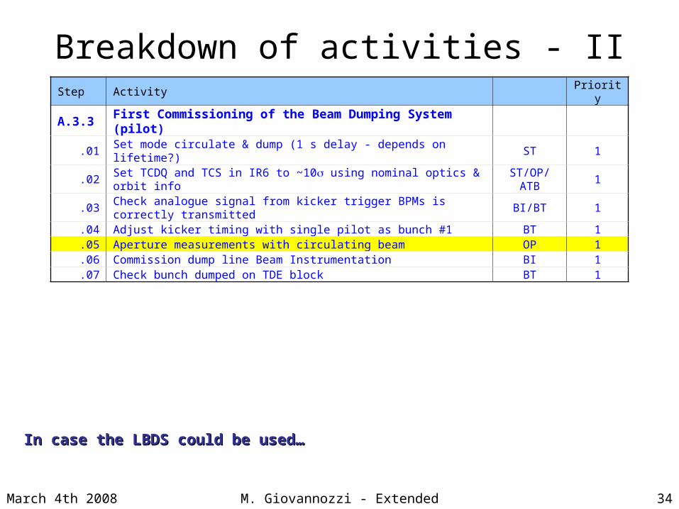
Breakdown of activities - II
34M. Giovannozzi - Extended LTC
Step Activity Priority
A.3.3 First Commissioning of the Beam Dumping System (pilot).01 Set mode circulate & dump (1 s delay - depends on lifetime?) ST 1.02 Set TCDQ and TCS in IR6 to ~10s using nominal optics & orbit info ST/OP/ATB 1.03 Check analogue signal from kicker trigger BPMs is correctly transmitted BI/BT 1.04 Adjust kicker timing with single pilot as bunch #1 BT 1.05 Aperture measurements with circulating beam OP 1.06 Commission dump line Beam Instrumentation BI 1.07 Check bunch dumped on TDE block BT 1
In case the LBDS could be used…In case the LBDS could be used…